1
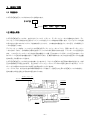
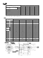
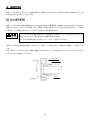
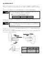
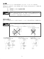
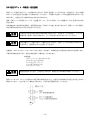
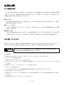
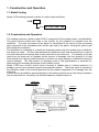
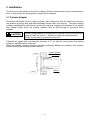
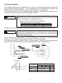
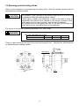
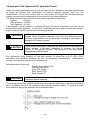
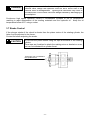
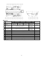
回転油圧シリンダ ROTATING HYDRAULIC CYLINDER C1FB 取扱説明書 INSTRUCTION MANUAL 重要 IMPORTANT 本取扱説明書をよく読み,内容を十分理解した 上でこの製品を使用してください。 この取扱説明書は大切に保管し,製品の所有者 が変わった場合,この説明書も新しい所有者に 手渡してください。 Be sure to read this instruction manual thoroughly before operating the rotating cylinder. Please save this manual. When ownership of this product is transferred, submit this manual to the new owner. 豊和工業株式会社 HOWA MACHINERY, LTD. 目 次 はじめに ······················································ 1 安全についてのインフォメーション 安全のために ······························ 1 ·················································· 2 1.構造と作動 1.1 形番表示 ··············································· 4 1.2 構造と作動 ··············································· 4 2.仕様 ······················································ 5 3.取付け方法 3.1 シリンダアダプタ ······································· 6 3.2 コネクチングパイプ 3.3 取付け・回り止め 3.4 配管 ····································· 7 ······································· 8 ··················································· 9 3.5 ドレンポート ··········································· 9 3.6 油圧ユニット・作動油・油圧回路 3.7 ストローク規制 3.8 試運転 ······················· 10 ······································· 11 ··············································· 12 4.保守・点検 4.1 作動油の点検 ········································· 13 4.2 分解・パーツリスト 限定保証 ··································· 14 ···················································· 15 はじめに 1. この取扱説明書は,C1FB 形回転油圧シリンダの標準形について説明しています。 2. この回転シリンダをご使用いただく前に,必ずこの取扱説明書を熟読し,取付け・運転・点検・保守について十 分に理解した上でご使用くださるようお願いします。 3. この取扱説明書の記載事項を守らない場合,作業者や周りの人を巻き込んだ重大な事故や機械の破損に結びつく 事があります。 4. この取扱説明書は常に手元に置き,紛失しないように大切に保管してください。 5. この取扱説明書と,この取扱説明書が対象とする製品についての問い合わせは下記へお願いします。 またこの取扱説明書を紛失したときも下記へ直接請求してください。 豊和工業株式会社 機械事業部 CE 営業グループ 営業グループ 機器チーム 機器チーム 〒452-8601 愛知県清須市須ケ口 1900 番地 1 TEL (052)408-1254 FAX (052)409-3766 6. この取扱説明書は SI 単位で書かれています。 従来単位による数値は以下の式で求めることができます。 圧 力 1MPa=10.197kgf/cm2 トルク 1N·m=0.10197kgf·m 安全についてのインフォメーション この製品を安全にご使用していただくために必要な警告事項を,安全警告シンボルと共に記載してあります。 警告 事項を良く読み,十分に理解してください。 この取扱説明書の警告メッセージをより良く理解していただくために,警告シンボルを次のように使い分けてあり ます。 危険 この表示は,取扱いを誤った場合に,重傷もしくは死に至る危険が切迫して生じることが想 定される事項を示します。 これらの警告メッセージには,危険を回避するのに講じなければならない予防措置が含まれ ます。 警告 この表示は,取扱いを誤った場合に,重傷もしくは死に至る可能性が想定される事項を示し ます。 これらの警告メッセージには,危険を回避するのに講じなければならない予防措置が含まれ ます。 注意 この表示は,取扱いを誤った場合に,軽微なケガの発生または機械の損傷が想定される状態 を示します。 当社は,あらゆる環境下における運転・操作・点検・保守のすべての危険を予測することはできません。 そのため, この取扱説明書に明記されている警告は,安全のすべてを網羅したものではありません。 また,「できないこと」や「してはいけないこと」は極めて多くあり,この取扱説明書にすべて書く事はできません。 この取扱説明書に「できる」と書いてない限り, 「できない」と考えてください。 もし,この取扱説明書に書かれ ていない運転・操作・点検・保守を行う場合,安全に対する必要な配慮は,すべて自分の責任でお考え願います。 -1- 安全のために ご使用の前に特に知っておいていただきたいこと,守っていただきたいことをまとめています。 必ずお読みくださ い。 危険 スピンドル回転中 スピンドル回転中は 回転中は,油圧ポンプの 油圧ポンプの電源 ポンプの電源を 電源を切ってはならない。 ってはならない。 把握したワークが飛散し危険です。 スピンドル回転中 スピンドル回転中は 回転中は,切換弁の 切換弁の操作を 操作を行ってはならない。 ってはならない。 把握したワークが飛散し危険です。 スピンドル回転中 スピンドル回転中は 回転中は,スピンドルカバーの中 スピンドルカバーの中に体の一部を 一部を入れて はならない。 はならない。 回転物に巻き込まれ危険です。 電磁弁は 電磁弁は,無通電時把握する 無通電時把握する回路 する回路とすること 回路とすること。 とすること。 把握したワークが飛散し危険です。 把握中は 把握中は,油圧力を 油圧力を一定に 一定に保つこと。 つこと。 把握したワークが飛散し危険です。 警告 回転シリンダの 回転シリンダの取付 シリンダの取付け・ 取付け・点検 け・点検・ 点検・保守の 保守の時には, には,電源を 電源を切ること。 ること。 回転物に巻き込まれ危険です。 回転シリンダの 回転シリンダの外周 シリンダの外周にはカバーを 外周にはカバーを付 にはカバーを付けること。 けること。 回転物に巻き込まれ危険です。 スピンドル回転中 スピンドル回転中は 回転中は,スピンドルカバーを開 スピンドルカバーを開いてはならない。 いてはならない。 回転シリンダが焼付いた時,部品が飛散し危険です。 使用回転数は 使用回転数は,回転シリンダおよびチャックの 回転シリンダおよびチャックの最高使用回転数 シリンダおよびチャックの最高使用回転数の 最高使用回転数の 範囲内で 範囲内で使用すること 使用すること。 すること。 破損,焼付きの原因となります。 落したり叩 したり叩いたりして衝撃 いたりして衝撃を 衝撃を与えないこと。 えないこと。 破損,焼付きの原因となります。 -2- 警告 取付けボルトの 取付けボルトの締付 けボルトの締付けは 締付けは確実 けは確実に 確実に行うこと。 うこと。 指定の締付けトルクを守らないと,ボルトの緩み,ボルトの破損により 部品,ワークの飛散が発生するおそれがあります。 ボルトのサイズと締付けトルクを下表に示します。 ボルトサイズ M8 M10 締付けトルク (N·m) 29.4 57.9 M12 101 使用油圧力はチャックの 使用油圧力はチャックの仕様 はチャックの仕様に 仕様に合わせること。 わせること。 ただし回転 ただし回転シリンダの 回転シリンダの最高使用油圧力 シリンダの最高使用油圧力を 最高使用油圧力を超えてはならない。 えてはならない。 過大な圧力を加えると回転シリンダ,またはチャックが破損するおそれ があります。 コネクチングパイプは コネクチングパイプは, ングパイプは,ねじ部 ねじ部に接着剤を 接着剤を塗布し 塗布し,適正なトルク 適正なトルク で締付けること 締付けること。 けること。 ねじが緩むとチャックのジョーストロークが短くなり,ワーク飛散の原 因となります。 接着剤:スリーボンド 1344 相当品を使用してください。 コネクチングパイプの締付けトルクを下表に示します。 ボルトサイズ M30×1.5 M40×1.5 締付けトルク (N·m) 120 210 油圧供給ライン 油圧供給ライン( ライン(P1, P1,P2 ポート) ポート)にはストレーナを組込 にはストレーナを組込むこと 組込むこと。 むこと。 回転シリンダ内に異物が混入すると,焼付きの原因となります。 20μm以下のストレーナを圧力供給ラインに組込んでください。 消耗品を 消耗品を含むすべての部品 むすべての部品は 部品は豊和工業へ 豊和工業へ注文してくださ 注文してください してください。 豊和工業が扱う以外の部品を用いて発生する事故については,その責を 負いかねます。 また豊和工業の純正部品を用いない限り,すべての保 証は無効になります。 注意 回転シリンダの 回転シリンダの取付 シリンダの取付け 取付け,取外しの 取外しの時 しの時,吊りベルトを使用 りベルトを使用すること 使用すること。 すること。 手を滑らして回転シリンダを落したり,腰をいためたりするおそれがあ ります。 作動油を 作動油を給油するときは 給油するときは, するときは,電源を 電源を切り火気厳禁のこと 火気厳禁のこと。 のこと。 引火するおそれがあります。 -3- 1.構造と 構造と作動 1.1 形番表示 C1FB 形回転油圧シリンダは次のように分類されます。 C1FB 90・ 90・100・ 100・120・ 120・140 サイズ 1.2 1.2 構造と 構造と作動 C1FB 形回転油圧シリンダは,大きく分けてシリンダ,ピストン,ディストリビュータより構成されており,ディ ストリビュータから供給された圧油によってシリンダ内をピストンが軸方向に移動します。そしてピストンの右端 に設けたねじ部にコネクチングパイプを接続することにより,この軸方向の動きをチャックに伝え,爪の開閉とワ ークの把握を行います。 ディストリビュータ部は,シリンダとともに回転するディストリビュータシャフトと,回転しないディストリビュ ータから成っており,その隙間から漏れた油はベアリングの冷却と潤滑に使われた後,ドレンポートから回収され ます。 このようにドレンポートから流出する油の量をドレン量,圧力の加わっているポートから圧力の加わってい ないポートへ短絡する油の量を内部リーク量と呼んでおり,仕様表に書かれたこれらの合計は油圧ポンプの吐出量 を決める上で必要になってきます。 C1FB 形回転油圧シリンダは逆止弁を内蔵していますから,スピンドル回転中に油圧系統に事故が起きても,内部 圧力の急激な低下が阻止されます。 逆止弁はディストリビュータシャフトの中に組み込まれていますから,ドレン ポートからの漏れにかかわりなく内部圧力を保持することができます。 リリーフバルブは,封入された油の体積が熱膨張によって増加し,内部圧力の上昇による回転シリンダの破損と, 過大な推力の発生を防止するために組込まれています。 ディストリビュータ ディストリビュータシャフト シリンダ ピストン リリーフバルブ 逆止弁 -4- 2.仕様 ・仕様 形式番号 C1FB 仕様 (cm2) ピストン面積 ピストンストローク 最高使用回転数 最高使用圧力 慣性モーメント(注 1) 質量 総ドレン量(注 2) 90 52.3 51.1 20 5000 3.5 0.017 12 2.4 押側 引側 (mm) (r/min) (MPa) (kg·m2) (kg) (L/min) 100 67.2 66.0 20 5000 3.5 0.016 12 2.4 120 101.8 100.5 25 5000 3.5 0.024 14 2.4 140 142.6 134.3 30 5000 3.5 0.044 17 2.4 注 1. この値の4倍が GD2 に相当します。 注 2. ISO VG32,油圧力:3.0MPa,出口油温:50℃ ・寸法 C1FB 形式番号 記号 90 100 120 140 90 144 100 144 120 157 140 182 J K 145 128 110 40 47 27 28 8 85 177 145 128 110 40 47 27 28 8 85 177 160 140 110 40 52 27 33 8 91 183 184 160 110 50 57 27 38 8 99 191 M1 M2 M3 M4 M5 N1 M30×1.5 30 25 36 18 M8 M30×1.5 30 25 36 18 M8 M30×1.5 30 25 36 18 M10 M40×1.5 35 35 46 18 M12 14 126 14 126 15 132 19 140 A B 内径 C D E F h7 Max. Min. Max. Min. G1 G2 H8 N2 P 8-M5 深サ 10 N2 20 6-M4 深サ 10 6-N1 10 6-M5 深サ 9 φ 52 P DR 2 45 ° 3-Rc3/8 ° 45 2-M5 深サ 10 7 26 14 39 3 M2 6 6 P 92 G2 K -5- 11 J 5 G1 M1 M4 B D F M3 C M5 E P2 φ20 P1 P 1 P2 DR P1 φ114 φ38 φ24H7 φ62H7 3 64 φ142 A:内径 φ31 3.取付け 取付け方法 回転シリンダを取付けるスピンドル後端の形状は,規格統一がされておらず千差万別であるのが実情ですから,最 も代表的な形状を一例として取上げます。 3.1 シリンダアダプタ シリンダアダプタ 回転シリンダの取付け位置は旋盤本体との干渉,配管の方向や位置,通風などを考慮して決めなければなりません。 回転シリンダには,スピンドルの起動,停止,振動による慣性力およびシリンダ出力が加わりますから,これに耐 え得るよう十分な剛性を持ったシリンダアダプタを設計する必要があります。 注意 シリンダアダプタは,面振れおよびインロの振れが 0.005mm 以下となるようにスピンドル に取付けてください。 振れが大きいと振動の原因になります。 また,ねじ部の緩みを防止するため,セットスクリュを設けてください。 回転シリンダ取付け時の振れを修正できるように,回転シリンダ取付け用インロ部の寸法公差は F7 で製作してく ださい。 また,回転シリンダの不つり合いは高度に調整してありますから,これを損なわないようシリンダアダプタのバラ ンスには十分の注意を払ってください。 シリンダアダプタ 0.005 A セットスクリュ 公差 F7 A スピンドル 0.005 A -6- 3.2 コネクチングパイプ コネクチングパイプ 回転シリンダの出力はコネクチングパイプを介してチャックに伝えられ,爪の開閉とワークの把握を行います。 コネクチングパイプをピストンにあらかじめねじ込んでから,回転シリンダを取付け,その後チャックを取付けま す。 コネクチングパイプは最大推力(ピストン面積×最高使用油圧力)に十分耐えられる強度が必要です。 警告 コネクチングパイプは,ピストンとコネクチングパイプのねじ部を十分脱脂した後,コネクチ ングパイプのねじ部に接着剤を塗り,適正なトルクで締付けます。 接着剤:スリーボンド 1344 相当品を使用してください。 コネクチングパイプの締付けトルクを下表に示します。 ボルトサイズ M30×1.5 M40×1.5 締付けトルク (N·m) 120 210 コネクチングパイプには回転シリンダとの結合部付近にレンチフラットを設けておき,これを利用してピストンロ ッドに締付けます。 注意 回転シリンダの回り止めは,ピストンロッドに設けたレンチフラットにスパナを掛けて行って ください。 シリンダ自体を固定してコネクチングパイプを締付けると,締付け力のために内 部の部品を破損することがあります。 コネクチングパイプのピストンロッドに対する締付け面の振れはコネクチングパイプの過度の傾斜を防ぐために 0.020mmT.I.R.以内としてください。 また,コネクチングパイプの自重による傾斜や振動を防止するためには,スピンドルのチャック取付け部近くに図 示のようなカラーを取付けると有効です。 コネクチングパイプ Oリング スピンドル カラー 0.1mm ピストンロッド コネクチングパイプ 基準面 インロ部 0.020 A 1.5 形式番号 A 30° Ra1.6 M3 Ra1.6 J1 11 記号 J1 90 M1 M1 M3 -7- C1FB 100 120 39 M30×1.5 f7 25 140 44 M40 ×1.5 35 3.3 3.3 取付け・ 取付け・回 け・回り止め 回転シリンダを取付ける上で大切なことは,回転シリンダに無理な力が加わらないようにすることです。 注意 回転シリンダを回転させると,作動油の粘性のためディストリビュータに多少のトルクが生じ ます。 このトルクによって生じる力を受けるために,配管材に鋼管を用いたり,ディストリビュータ を旋盤の一部へ固定したりすると,回転シリンダ全体に無理な力が加わり,故障や振動の原因 になります。 ですから,配管材にはフレキシブルホースを使用し,ディストリビュータの回 り止めには図示のような余裕のあるフォークを用いてください。 回転シリンダ取付け時の振れは,シリンダ外周で 0.015mm T.I.R. 以下としてください。 警告 回転シリンダの取付けボルトは確実に締付けてください。 ボルトのサイズと締付けトルクを下表に示します。 ボルトサイズ M8 M10 締付けトルク (N·m) 29.4 57.9 M12 101 取付けボルト穴の傍らには凹印があります。 それ以外は本品を構成しているボルトですので注意してください。 0.015 以下 凹印 1~2mm 1~2mm フォーク -8- 3.4 3.4 配管 回転シリンダのディストリビュータ部には油圧供給ポートが 2 ヶ所と,ドレンポートが 1 ヶ所あります。 それぞれのポートの区別はポートの近くに刻印を施して表示してあります。表示された文字とポートの種類との関 係は以下のとおりです。 P1 P2 DR 警告 油圧供給ポート(ピストンは引側方向へ移動) 油圧供給ポート(ピストンは押側方向へ移動) ドレンポート 油圧回路は,配管内のゴミを完全に取除いてから組付けてください。 配管内にゴミが入ると, 回転シリンダ焼付きの原因となります。 また,回転シリンダの性能を保持するために,必ず 20μm以下のストレーナを圧力供給ラインに組込んでください。 3.5 3.5 ドレンポート 回転シリンダは回転部にオイルシールを用いていますから,ドレンポートに多少の背圧が加わっても問題ありませ ん。 ドレンポートに過度の背圧を加えると外部漏れの原因になります。 背圧は 0.015MPa 以下と してください。 回転シリンダの中心に対するドレンホースの高さは 1.7m 以下としてください。 ドレンホースが折れ曲がっている。 1.7m 以上 注意 -9- 3.6 3.6 油圧ユニット・ 油圧ユニット・作動油 ユニット・作動油・ 作動油・油圧回路 回転シリンダ専用に油圧ユニットを設置するときには,使用する回転シリンダの大きさ,許容油圧力,および必要 なチャックの把握力などを考慮して仕様を決定してください。不必要に大きなモータや吐出量の多すぎるポンプを 使用すると,油温が上昇し弊害が発生するおそれがあります。 通常,回転シリンダ用油圧ユニットは,吐出量 25L/min,圧力 3.5MPa,タンク容量 40~60L 程度のものが使 用されます。 取付機械自体に油圧源がある場合,油圧回路を分岐して使用しても差し支えありませんが,回転シリンダの回路に は必ず専用の減圧弁および圧力計を設けてください。 注意 油圧源の圧力設定に調圧応答性の悪い減圧弁を用いると,過大なサージ圧が発生し,シリンダ の作動不良・破損につながりますので,サージ圧を低くおさえるようにしてください。 注意 最低吐出量がドレン量と内部リーク量の合計を下回ると,回転シリンダの内部圧力が保てなく なりますから,回路設計には十分注意してください。 作動油は,40℃で 32mm2/sec(ISO VG32 相当)の粘度で,対摩耗性および消泡性のあるものを推奨します。 不適切な作動油を用いると,製品の寿命を著しく縮めることがあります。 推奨油種 ダフニースーパーマルチオイル 32 ダイヤモンドルブ RO32 モービル DTE(ライト) シェルテラスオイル 32 エッソテレッソ 32 注意 作動油を給油するときは,引火を防止するため,電源を切り火気厳禁で実施してください。 回転シリンダには,スピンドル回転中に油圧系統に事故が起きても,内部圧力の急激な低下を阻止する逆止弁が内 蔵されています。 逆止弁を正しく機能させるために,下図の油圧回路設計をしてください。 -10- 危険 ピストン動作方向の切換えを 4 ポート 2 位置の電磁弁で行う場合,無通電時にワークを把握す るように油圧回路を設計してください。 さもないと停電時に逆止弁が正しく機能しないため, 把握したワークが飛散し危険です。 回転シリンダを高速回転で連続使用すると,作動油の油温が上昇します。 高温になるとシール材および作動油の劣 化が急速に進行します。 クーラを使用して,油温が 60℃を超えないようにしてください。 3.7 3.7 ストローク規制 ストローク規制 チャックのプランジャストロークが回転シリンダのストロークよりも短い場合,チャックのプランジャストローク に合わせて回転シリンダのストロークを規制する場合があります。 実施に当たっては当社にお問合せください。 注意 回転シリンダ後部のタップを使用して,ストロークを規制しないでください。 これらは回転継手やブラケットやカバーを取付けるために設けてあり,シリンダ推力に耐える 構造になっていません。 これらのタップは,シリンダ推力に 耐える構造になっていません。 -11- 3.8 3.8 試運転 ① 作動油を油圧ユニットの注油口から油面計の上限まで入れます。 ② まず油圧力を 0.5MPa 以下に設定し,作動に異常がないか確認します。 その後,徐々に最高使用圧力まで上昇 させ,各部の油漏れや異常がないか調べます。 ③ スピンドルを 200~300r/min で回転させ,各部の振動や異音に注意しながら徐々に回転数を上昇させます。 警告 スピンドル回転中は,回転部に不注意に体を近付けたり,回転部に触れたりしないように十分 注意してください。 ④ 逆止弁を内蔵しているため,シリンダの封入圧力が上昇して作動しなくなることがあります。 その際は,下記 の操作により対処してください。 (1) まずスピンドルの回転を止めます。 (2) 設定油圧力を,現在の設定油圧力より 0.5MPa 上げて,シリンダの作動を確認します。 シリンダが作動で きましたら元の設定油圧力に戻します。 (3) 作動しなかった場合は,設定油圧力をさらに上げてシリンダの作動を確認します。 設定油圧力は 0.5MPa ずつ上げてゆき,上限は 4.5MPa とします。 シリンダが作動できましたら元の設定油圧力に戻します。 (4) これまでの操作を行っても作動しない場合は,設定油圧力を元に戻して電源を切り,回転シリンダを室温ま で冷却した後,(2),(3)の操作を行います。 (5) それでも作動しない場合は,逆止弁による封入圧力上昇以外の原因が考えられます。 チャックのドロース クリュを緩めて連結を外し,シリンダの作動を確認してください。 注意 油圧力を最初に設定した値より降下させるとシリンダは作動しなくなることがあります。 これは内蔵している逆止弁によってシリンダ内部に封入された油圧力が降下後の圧力では開 放できないことが原因であり,異常ではありません。 降下後の油圧力が,シリンダ内部に封入された油圧力の 5 分の 1 以下の時に,この現象がおこ ります。 油圧力を最初に設定した値より降下させる必要がある場合には,中間の油圧力で一旦シリンダ を作動させてから目的の油圧力まで降下させてください。 -12- 4.保守・ 保守・点検 4.1 作動油の 作動油の点検 ベアリングの冷却と潤滑はドレンを利用して行われますから,清浄な作動油を使用する限り特別の潤滑油は必要あ りません。 ですから,作動油を常に点検して清浄に保つことが,この回転シリンダの保守にとって最も大切です。 作動油の点検は次の点に注意して行ってください。 ●水分の除去 空気の温度や湿度が高い場合には,水分が油圧ユニットのタンクの底にたまることがありますから,1週間に1 回程度の割合で排出してください。 ●ストレーナの洗浄 1ヵ月に1回程度油圧ユニットのストレーナを外し,洗浄油で洗ってから,内側から圧縮空気を吹き込んで異物 を取除いてください。 ●作動油の交換 1年に1回程度作動油を交換してください。 交換の際は油温を上げてから行うのが効果的で,古い油はできる だけ残らないように取出します。 汚れが特にひどい場合は,洗浄油でタンク内部を洗浄すれば効果的です。 4.2 分解・パーツリスト 分解・パーツリスト 回転シリンダは,正しく取付けて清浄な作動油を使用していれば,きわめて長い寿命を保つことができます。 しか しもし何らかの原因で故障が生じた場合には,分解して必要に応じて部品を交換しなければなりません。 注意 回転シリンダのシールや構成部品をピストン作動回数 25 万往復毎に細部まで分解点検し,シ ールの摩耗や部品の損傷がある場合は交換してください。 ☆分解手順 ① 取付けボルトを外してシリンダ(A)をディストリビュータシャフト(B)から外します。 ② ピストン(C)を抜き出します。 ③ 取付けボルトを外してストッパ(D)を外します。 ④ ディストリビュータ(E)にギャー抜きなどの工具を掛けて,ベアリング(F) ,オイルシール(G)とともに抜 出します。 ⑤ 残りのベアリング(14)とオイルシール(13)を抜出します。 ⑥ カラー(H)を抜出します。 ⑦ プラグ(I)を外します。プラグは接着剤で緩み止めが施されていますので注意してください。 ⑧ 六角穴付きプラグ(J)を外します。 ⑨ 逆止弁(15)とスペーサ(K)を抜出します。逆止弁は本体部分とプランジャ部分が分離しますので注意して ください。 ⑩ 軸止め輪を外してリリーフバルブ(16)を外します。 -13- ☆パーツリスト 番号 品 名 C1FB 1 O リング 90 P80 (JIS) 100 P90 (JIS) 120 P110 (JIS) 140 P130 (JIS) 2 O リング G95 (JIS) G95 (JIS) G115 (JIS) G135 (JIS) 3 ロッドパッキン PS-40 (阪上製作所) 4 ロッドパッキン 5 ダストシール PS-38 (阪上製作所) SER-40 (阪上製作所) 6 O リング 7 8 9 10 11 12 13 14 15 16 PS-50 (阪上製作所) O リング O リング O リング O リング O リング O リング オイルシール ボールベアリング チェックバルブ リリーフバルブ SER-50 (阪上製作所) G35 (JIS) (JIS) (*1) C1FB90 は 2 個,それ以外は 1 個 -14- 1 (*1) 1 or 2 1 1 G25 P8 (JIS) P16 (JIS) AS568-016 P9 (JIS) S60 (NOK) G60 (JIS) AC3527A1 (NOK) 6812 (JIS) 豊和工業専用部品 豊和工業専用部品 数 量 1 1 1 2 4 2 1 1 2 2 2 2 限 定 保 証 売り主は製品が,頒布されている仕様条件に従って製造されたもので,材料上および/または仕上げ上欠陥 がないことを保証いたします。 売り主は,工場へ元のまま返品された運送費前払いのもので,売り主が点検して材料および/または仕上げ に欠陥があると判断した製品は,売り主の自由意志で,修理もしくは交換をいたします。 前記のものにつ いては,それが売り主の保証違反に対する唯一の救済となるものとします。 売り主は,これに限定 これに限定されるわけではありませんが 限定されるわけではありませんが, されるわけではありませんが,市場性や 市場性や市販性に 市販性に関する保証 する保証, 保証,特定の 特定の目的または 目的または用途 または用途 に関する保証 する保証, 保証,もしくは特許侵害 もしくは特許侵害に 特許侵害に対する保証 する保証など 保証など本保証条件以外 など本保証条件以外のものは 本保証条件以外のものは, のものは,明示の 明示の保証であろうと 保証であろうと黙示 であろうと黙示の 黙示の 保証であろうと 保証であろうと, であろうと,なんらの保証 なんらの保証もいたしません 保証もいたしません。 もいたしません。売り主は,いかなる直接的損害 いかなる直接的損害, 直接的損害,付帯的もしくは 付帯的もしくは間接的 もしくは間接的な 間接的な 損害金, 損害金,あるいは欠陥製品 あるいは欠陥製品もしくは 欠陥製品もしくは製品 もしくは製品の 製品の使用に 使用に起因する 起因する損害金 する損害金または 損害金または費用 または費用については 費用については, については,なんら責任 なんら責任はない 責任はない ものといたします。 ものといたします。 -15- Table of Contents Precautions 1 For Safe Operation 1 Safety Precautions 2 1. Construction and Operation 1.1 Model Coding 4 1.2 Construction and Operation 4 2. Specifications 5 3. Installation 3.1 Cylinder Adaptor 6 3.2 Connecting Pipe 7 3.3 Mounting and Anti-rolling Guide 8 3.4 Piping 9 3.5 Drain Port 9 3.6 Hydraulic Unit, Hydraulic Oil, Hydraulic Circuit 10 3.7 Stroke Control 11 3.8 Trial Operation 12 4. Maintenance and Inspection 4.1 Check of Hydraulic Oil 13 4.2 Overhaul and Parts List 14 LIMITED WARRANTY 15 Precautions 1. This instruction manual describes model C1FB Rotating Hydraulic Cylinder Standard Model. 2. Please read this manual carefully and fully understand the procedures for installation, operation, inspection, and maintenance before operating the rotating cylinder. 3. Ignoring any instructions in this manual may result in a serious accident or machine damage, leading to injury to the operator or personnel near the machine. 4. Please save this manual and keep it handy at all times. 5. Please contact us (phone and fax numbers are shown below) for information regarding this manual and the objective product. Another copy of this manual is also available from the following address: HOWA MACHINERY, LTD. MACHINE TOOL ACCESSORIES TEAM SALES GROUP CREATIVE ENGINEERING DIVISION MACHINERY DEPT 1900-1, SUKAGUCHI, KIYOSU, AICHI, 452-8601 JAPAN Phone : International access code-81-52-408-1254 Facsimile: International access code-81-52-409-3766 6. The values of this manual are described in SI unit system. Values of former unit system can be obtained by following calculations. Pressure 1MPa=10.197kgf/cm2 Torque 1N·m=0.10197kgf·m For Safe Operation This manual contains warning messages for safe operation that are indicated by Safety Alert Symbols. Carefully read and fully understand these messages. The danger levels of the Safety Alert Symbols are defined below. DANGER Indicates an imminently hazardous situation which, if not avoided, will result in death or serious injury. These warning massages include the preventive actions those are indispensable to avoid danger. WARNING Indicates a potentially hazardous situation which, if not avoided, could result in death or serious injury. These warning massages include the preventive actions those are indispensable to avoid danger. CAUTION Indicates a potentially hazardous situation which, if not avoided, could result in minor injury or machine damage. It is impossible to predict all hazardous situations that may occur during operation, inspection, and maintenance of the rotating cylinder under various circumstances. Accordingly, the warning messages described in this manual do not cover all hazardous situations. Also, there are too many operations that cannot or should not be performed using the rotating cylinder to be completely described in this manual. We cannot assume any responsibility for damage or accidents caused through operation, inspection, or maintenance of the rotating cylinder that is not specified in this manual. -1- Safety Precautions Read and understand the following precautions before using the rotating cylinder, and observe them during operation. DANGER Never turn off the power of the hydraulic pump during spindle rotation. Danger by discharge of workpiece. Never operate the selector valve during spindle rotation. Danger by discharge of workpiece. Never enter the spindle cover during spindle rotation. Danger of entanglement with rotating section. Route solenoid valve so as to chuck even if the power is interrupted. Danger by discharge of workpiece. Keep the hydraulic pressure constant while workpiece is gripped. Danger by discharge of workpiece. WARNING Turn off the power before installation, inspection, and maintenance of the rotating cylinder. Danger of entanglement with rotating section. Cover the periphery of the rotating cylinder. Danger of entanglement with rotating section. Never open the spindle cover during spindle rotation. Danger by discharge of parts in case of seizure of rotating cylinder. Keep the speed of the rotating cylinder and the chuck below the upper limit. Danger by machine damage or seizure. Never shock. Danger by machine damage or seizure. -2- WARNING Secure mounting bolts to specified torque. Danger by discharge of workpiece due to loosened or damaged bolts caused by not using specified tightening torque. Bolt size and tightening torque Bolt size Tightening torque (N·m) M8 29.4 M10 57.9 M12 101 Set hydraulic pressure to chuck specifications, and keep it below the upper limit. Danger by damage of rotating cylinder or chuck caused by excessive hydraulic pressure. Coat the threaded section of connecting pipe with adhesive, and tighten it with the specified torque. Danger by discharge of workpiece caused by shortened jaw stroke due to loose screw. Adhesive: Use ThreeBond 1344 or equivalent Tightening torque for connecting pipe Bolt size Tightening torque (N·m) M30×1.5 120 M40×1.5 210 Attach a strainer in the hydraulic pressure supplying line (Ports P1 and P2). Danger by seizure caused by foreign matters included in the rotating cylinder. Use a strainer with 20 µm filterability or better. Order all parts for this rotating cylinder from Howa machinery, Ltd. Howa assumes no responsibility for accidents which occur when other than Howa genuine parts are used. Any and all warranties are void unless only Howa genuine parts are used. CAUTION Use lifting belt when attaching or detaching rotating cylinder. Danger by dropping of rotating cylinder from your hands. an excessive stress causing your lumbar injury. Danger by Turn off the power source before supplying hydraulic oil. and flame away during supplying. Keep fire Danger by flaming of hydraulic oil. -3- 1. Construction and Operation 1.1 Model Coding Model C1FB rotating hydraulic cylinder is model coded as follows: C1FB ・100・ ・120・ ・140 Size 90・ 1.2 Construction and Operation The rotating hydraulic cylinder model C1FB is composed of the cylinder, piston, and distributor. The piston travels axially back forth in the cylinder by the hydraulic oil supplied from the distributor. The axial movement of the piston is transmitted to the chuck by the connecting pipe connected to the threaded section on the right end of the piston, causing the jaws to grip and release the workpiece. The distributor is composed of a distributor shaft that rotates with the cylinder and a distributor that does not rotate. Oil that leaks between the distributor shaft and the distributor is used to cool and lubricate the bearings and is then collected via the drain port. The quantity of oil that leaks from the drain port is regarded as the amount of drainage, and the quantity of oil that flows directly from the port under pressure to another not under pressure is called the amount of internal leakage. The total amount of drainage noted in the specifications is important for determining the necessary discharge of the hydraulic pump. Model C1FB has a built-in check valve to prevent a sudden drop in internal pressure if a problem occurs in the hydraulic system during spindle rotation. The check valve is mounted in the distributor shaft so the internal pressure can be retained regardless of oil leakage from the drain port. A relief valve is provided to prevent damage to the rotating cylinder due to the rising of pressure and excessive thrust, caused by the thermal expansion of pressurized oil. Distributor Distributor shaft Cylinder Piston Relief valve Check valve -4- 2. Specifications ・Specifications Series number C1FB Specifications 90 52.3 51.1 20 5000 3.5 0.017 12 2.4 Extend Effective piston area (cm2) Retract Piston stroke (mm) Max. speed (r/min) Max. pressure (MPa) Moment of inertia J (Note 1) (kg·m2) Weight (kg) Total leakage (Note 2) (L/min) 100 67.2 66.0 20 5000 3.5 0.016 12 2.4 120 101.8 100.5 25 5000 3.5 0.024 14 2.4 140 142.6 134.3 30 5000 3.5 0.044 17 2.4 2 Note 1. The four times of this value is equivalent to GD . Note 2. ISO VG32, Pressure : 3.0MPa, Oil temperature at the exit port : 50°C ・Dimensions C1FB Series number Symbol A B C D E F I.D. h7 Max. Min. Max. Min. G1 G2 J K M1 M2 M3 M4 M5 N1 N2 P H8 8-M5 Depth 10 6-M4 Depth 10 6-M5 Depth 9 100 100 144 145 128 110 40 47 27 28 8 85 177 M30×1.5 30 25 36 18 M8 14 126 120 120 157 160 140 110 40 52 27 33 8 91 183 M30×1.5 30 25 36 18 M10 15 132 N2 20 140 140 182 184 160 110 50 57 27 38 8 99 191 M40×1.5 35 35 46 18 M12 19 140 6-N1 10 52 3 P2 M3 F E D B M5 DR 2 45 ° 26 39 45 ° 3-Rc3/8 2-M5 Depth 10 7 14 3 G2 6 6 92 J K -5- M2 11 P 5 G1 M1 M4 P1 φ20 C P2 DR P1 φ114 A : I.D. P P1 64 φ31 φ142 φ62H7 φ38 φ24H7 φ 90 90 144 145 128 110 40 47 27 28 8 85 177 M30×1.5 30 25 36 18 M8 14 126 3. Installation The rear end of the spindle to which the rotating cylinder is attached has various configurations. Here, a typical rear end configuration is shown as an example. 3.1 Cylinder Adaptor Determine the location for the rotating cylinder, with interference with the lathe body, direction and position of piping, draft and other necessary factors taken into account. Since the rotating cylinder is subjected to inertia force resulted from starting, stopping and vibration of the spindle and cylinder output force, the cylinder adaptor must be rigid enough to overcome these stresses. CAUTION Set the cylinder adaptor to the spindle so that the runout of the face and spigot is 0.005 mm or less. Excessive runout will cause vibration. Provide a set screw to secure the screw joint. Fabricate the spigot with a dimensional tolerance of F7 so that the runout when the rotating cylinder is installed can be corrected. Since the rotating cylinder has been accurately balanced, balance the adaptor very carefully without affecting the rotating cylinder balance. Cylinder adaptor Set screw F7 0.005 A Tolerance A Spindle 0.005 A -6- 3.2 Connecting Pipe The rotating cylinder output is transmitted to the chuck by via the connecting pipe, causing the jaws to grip and release workpiece. The connecting pipe is first screwed into the piston, the rotating cylinder is installed, and the chuck is connected to the connecting pipe. The connecting pipe shall have enough bearing capacity to withstand the maximum thrust (multiply the piston area by the maximum hydraulic pressure). Completely decrease the piston and the threaded section of the connecting pipe, coat the threaded section of the connecting pipe with adhesive, and tighten it to the specified torque. WARNING Adhesive: Use ThreeBond 1344 or equivalent Tightening torque for connecting pipe Bolt size Tightening torque M30×1.5 120 (N·m) M40×1.5 210 A wrench flat is to be provided on the connecting pipe as close as possible to the piston rod. Place a spanner on the wrench flat provided on the piston rod to withstand the fastening torque for connecting pipe. Tightening the connecting pipe holding the cylinder may result in damage to internal parts due to fastening torque. CAUTION The runout of the tightening surface of the connecting pipe to the piston rod should be within 0.020 mm T.I.R. to prevent the excessive inclination of the connecting pipe. To prevent the excessive inclination due to the dead weight or vibration of the connecting pipe, attach a collar inside the spindle as close as possible to the chuck as shown below. Connecting pipe O ring Spindle Connecting pipe 0.1mm Collar Piston rod Datum end face Spigot 0.020 A 11 1.5 Series number 30 ° A Ra1.6 M3 Ra1.6 J1 Symbol J1 M1 M1 M3 -7- 90 C1FB 100 120 39 M30×1.5 f7 25 140 44 M40 ×1.5 35 3.3 Mounting and Anti-rolling Guide What is most important in accomplishing the piping work is that the rotating cylinder must be protected from excessive stress. CAUTION The viscosity of the hydraulic oil will cause a slight amount of torque on the distributor when the rotating cylinder rotates. If steel piping is used or the distributor is fixed to the lathe in order to compensate the reactive force caused by this torque, excessive force will be applied to the rotating cylinder, and will lead to problems. Use flexible hose for the piping and use a fork with some margin as shown below for the anti-rolling guide of the distributor. The runout of the cylinder periphery should be 0.015 mm or less. WARNING Secure the mounting bolts. Bolt size and tightening torque Bolt size Tightening torque (N·m) M8 29.4 M10 57.9 M12 101 There is a spot sinking by the side of the each mounting bolt hole. Note that the other bolts are for assembling this rotating cylinder. 0.015mm or less Spot sinking 1~2mm 1~2mm Fork -8- 3.4 Piping Two hydraulic oil supply ports and one drain port are provided on the rotating cylinder distributor. These ports are indicated by the marking provided next to the port. The meaning of marked characters and the port type are shown below. P1: Hydraulic oil supply port (Piston moves retract) P2: Hydraulic oil supply port (Piston moves extend) DR: Drain port WARNING Thoroughly remove any contaminant from the inside of the pipe before installing the hydraulic circuit. Contamination may cause seizure of the rotating cylinder. To maintain high performance of the rotating cylinder, install a strainer with 20 µm filterability or better in the pressure supplying line. 3.5 Drain Port Each of models included in this manual has oil seals to avoid the leakage under the certain back pressure at the drain port. Applying excessive back pressure to the drain port may cause the external leakage. The maximum back pressure allowed to the drain port is 0.015 MPa. The maximum height of the drain hose passage above the center line of the rotating cylinder should be less than 1.7 m. Drain hose is tortured. More than 1.7m CAUTION Never configure piping as shown below. -9- 3.6 Hydraulic Unit, Hydraulic Oil, Hydraulic Circuit When providing a dedicated pump unit for the hydraulic unit, determine the pump specifications by taking the cylinder size, permissible oil pressure, required gripping force, etc. into consideration. Do not use a motor with too much power or a pump with excessive delivery capacity, because the oil temperature will rise and this may cause problems. The specifications of the pump unit for the rotating cylinder are as follows: Delivery: 25 L/min Max. pressure: 3.5 MPa Tank capacity: 40 - 60 L If the hydraulic unit is located in a machine on which the chuck is mounted, its circuit can be branched for chuck operation. In this case, a dedicated pressure reducing valve and pressure gage must be provided in the circuit of the rotating cylinder. CAUTION Keep the surge pressure low. If the pressure of the hydraulic unit is adjusted using a pressure reducing valve with low response speed, excessive surge pressure will be generated, resulting in malfunction or damage to the rotating cylinder. CAUTION If the minimum discharge is less than the total amount of drainage and internal leakage, it becomes impossible to maintain the internal pressure of the rotating cylinder. Pay attention to this point when designing the hydraulic circuit. We recommend using hydraulic oil that has viscosity of 32mm2/sec at 40°C (ISO VG32) equivalent with abrasion resistance as well as defoaming characteristics. Inappropriate hydraulic oil may extremely shorten the product life. Recommended oil types are : Daphne Super Multi Oil 32 Diamond Lub RO 32 Mobil DTE (Light) Shell Tellus Oil 32 Esso Teresso 32 CAUTION Turn off the power source before supplying hydraulic oil. flame away during supplying. Keep fire and The rotating cylinder has a built-in check valve to prevent a sudden drop in the internal pressure when a problem occurs in the hydraulic system during spindle rotation. To keep the check valve effective, design the hydraulic circuit as shown below. - 10 - DANGER If the piston movement direction is changed with the 4-port 2-position solenoid valve, design the hydraulic circuit so as to chuck even if the solenoid valve is demagnetized. Ignoring this instruction may result in the malfunction of the check valve and danger caused by discharging of the workpiece. Continuous high speed operation causes a considerable increase of the oil temperature, resulting in rapid deterioration of the sealing materials and the hydraulic oil. Keep the oil temperature below 60°C using a cooler. 3.7 Stroke Control If the plunger stroke of the chuck is shorter than the piston stroke of the rotating cylinder, the latter may be adjusted to the former. Contact us before adjusting the stroke. CAUTION Do not limit the piston stroke using the taps at the back of the rotating cylinder. These taps are furnished to attach the rotating union or bracket or cover, and can not withstand the cylinder thrust. These taps can not withstand the cylinder thrust. - 11 - 3.8 Trial Operation 1) Pour the hydraulic oil into the oil port to the upper limit of the oil level gage. 2) Set the hydraulic pressure to 0.5MPa or less, and check for abnormality in the rotating cylinder operation. Then, gradually raise the pressure to the maximum pressure while checking for oil leakage and abnormalities in each part. 3) Rotate the spindle at 200 to 300 r/min, and gradually raise the speed while checking for vibration and abnormal sound in each part. WARNING Take care not to approach or touch the rotating section during spindle rotation. 4) Since the check valve is provided, the cylinder may become inoperative when the sealed pressure is raised. In this case, follow the procedures below. (1) Stop the spindle. (2) Raise the pre-set pressure by 0.5 MPa, and check the cylinder operation. If the cylinder operates correctly, bring the pre-set pressure back to the original level. (3) If the cylinder fails to operate correctly, further raise the pre-set pressure by 0.5 MPa each until it reaches 4.5 MPa while checking the cylinder operation. When the cylinder operation is recovered, bring the pre-set pressure back to the original level. (4) When the correct cylinder operation cannot be recovered even when the pre-set pressure is brought up to the upper limit (4.5 MPa), bring the pre-set pressure back to the original level, and turn off the power. Then, cool down the rotating cylinder to room temperature, and repeat procedures (2) and (3) above. (5) If the cylinder operation never recovers even after it is cooled, the cylinder malfunction may be caused something other than the sealed pressure rising due to the check valve. Loosen the draw screw of the chuck and take off the connection to check the cylinder operation. CAUTION Lowering the operating hydraulic pressure from the initial one may cause the malfunction of this cylinder. This is caused by the reason that lower hydraulic pressure enclosed to the cylinder by the internal check valve cannot be released. Therefore, this phenomenon is not defective. This phenomenon occurs when the lowered hydraulic pressure is one fifth or less to the initial one. In the case of lowering the hydraulic pressure from the initial value, activate the cylinder with intermediate hydraulic pressure, and then lower to the target value. - 12 - 4. Maintenance and Inspection 4.1 Check of Hydraulic Oil The bearing is cooled and lubricated with drain so that any special lubricating oil is not necessary as long as the hydraulic oil is clean. Therefore, for the sake of maintenance of this rotating cylinder, it is most important to keep the hydraulic oil clean at all times. Check the hydraulic oil in the following respects. ● Remove of condensation When the temperature or humidity is high, condensation may be accumulated on the bottom of the hydraulic unit tank. Remove condensation once a week. ● Cleaning of strainer Remove and clean the strainer of the hydraulic unit once a month by washing it in flushing oil and blowing compressed air through it from the inside. ● Change of hydraulic oil Change the hydraulic oil once a year. Preheating the oil helps when changing the oil. Replace the old oil entirely with fresh oil. If the old oil is extremely contaminated, clean the interior of the tank with flushing oil before replacing it with fresh oil. 4.2 Overhaul and Parts List The rotating cylinder will remain in excellent operating condition for many years as long as it is properly installed and the hydraulic oil is clean. If failure should occur for any reason, disassemble the rotating cylinder and replace defective parts if necessary. CAUTION Overhaul the seal and parts of the rotating cylinder in detail when the actuation of the piston reaches to every 250,000 strokes. If the wear of the seal or damage of the part is found, replace it (them). ☆Disassembling procedure for rotating cylinder 1) Remove the mounting bolts and detach the cylinder (A) from the distributor shaft (B). 2) Extract the piston (C). 3) Remove the mounting bolts and detach the stopper (D). 4) With a gear remover or like tool attached to distributor (E), extract the distributor (E) with bearing (F) and oil seal (G). 5) Extract the bearing (14) and oil seal (13). 6) Extract the collar (H). 7) Remove the plug (I). Note that the plug is secured with adhesive. 8) Remove the hexagon socket plug (J). 9) Extract the check valve (15) and spacer (K). Note that the main body and the plunger of the check valve are separated. 10) Remove the snap rings and detach the relief valves (16). - 13 - ☆Parts list No. Parts Name C1FB 1 O ring 90 P80 (JIS) 2 O ring G95 (JIS) 3 Rod packing 4 Rod packing 5 Rod wiper 6 7 8 9 10 11 12 13 14 15 16 O ring O ring O ring O ring O ring O ring O ring Oil seal Ball bearing Check valve Relief valve 100 P90 (JIS) 120 P110 (JIS) 140 P130 (JIS) G95 (JIS) G115 (JIS) G135 (JIS) PS-40 (Sakagami Seisakusho) PS-50 (Sakagami Seisakusho) PS-38 (Sakagami Seisakusho) SER-40 (Sakagami Seisakusho) G25 (JIS) P8 (JIS) P16 (JIS) AS568-016 P9 (JIS) S60 (NOK) G60 (JIS) AC3527A1 (NOK) 6812 (JIS) Howa genuine part Howa genuine part (*1) C1FB90 use two parts, and other sizes use one part. - 14 - Q'ty 1 (*1) 1 or 2 1 1 SER-50 (Sakagami Seisakusho) G35 (JIS) 1 1 1 2 4 2 1 1 2 2 2 2 LIMITED WARRANTY Seller warrants its products to be manufactured in accordance with published specifications and free from defects in material and/or workmanship. Seller, at its option, will repair or replace any products returned intact to the factory, transportation charges prepaid, which seller, upon inspection, shall determine to be defective in material and/or workmanship. The foregoing shall constitute the sole remedy for any breach of seller's warranty. Seller makes no warranties, either express or implied, except as provided herein, including without limitation thereof, warranties as to marketability, merchantability, for a particular purpose or use, or against infringement of any patent. In no event shall seller be liable for any direct, incidental or consequential damages of any nature, or losses or expenses resulting from any defective product or the use of any product. 20120607 - 15 -


![[ PSG-1用チャンバーブロックの組込み方 ] - X-fire](http://vs1.manualzilla.com/store/data/006603875_3-59ccb51fb3b4b7265b916dc4b2794391-150x150.png)