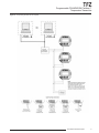
1
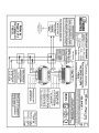
TFZ
Programmable FOUNDATION Fieldbus™
Temperature Transmitter
TFZ
Programmable FOUNDATION Fieldbus™
Temperature Transmitter
June 2013
238-705-00C
All product names are registered trademarks of their respective companies.
Table of Contents
Introduction.............................................................................................................................................. 4
About this Manual............................................................................................................. 4
The TFZ............................................................................................................................ 4
Model and Serial Numbers............................................................................................... 4
Specifications.................................................................................................. 5
Dimensions....................................................................................................................... 7
Necessary Equipment Table.............................................................................................. 8
FOUNDATION Fieldbus Interface................................................................. 10
®
Function Blocks............................................................................................. 11
Description of FOUNDATION Fieldbus Blocks................................................................ 12
Resource Block (Index Number 1000)............................................................................ 12
Temperature Transducer Block (Index Number 1200)..................................................... 16
Analog Input Block (Index Number 1100)....................................................................... 25
Input Settings................................................................................................. 28
TFZ Configuration......................................................................................... 30
Transducer Block Configuration...................................................................................... 30
Analog Input Block Configuration.................................................................................... 34
Installation...................................................................................................... 36
Mounting the TFZ............................................................................................................ 36
Making the Electrical Connections.................................................................................. 36
Recommended Ground Wiring Practices........................................................................ 36
CE Conformity................................................................................................................. 36
Operation........................................................................................................ 36
Maintenance.................................................................................................................... 36
Customer Support......................................................................................... 36
Installation in Hazardous Locations............................................................ 37
TFZ
Programmable FOUNDATION Fieldbus™
Temperature Transmitter
Introduction
This is the user’s manual for Moore Industries’ TFZ
Programmable FOUNDATION Fieldbus™ Temperature
Transmitter. It contains all of the information needed
to configure, install, operate and maintain the TFZ.
About this Manual
Pay particular attention wherever you see a “Note”,
“Caution” or “WARNING ”.
Note– Information that is helpful for a procedure,
condition or operation of the unit.
Caution– Hazardous procedure or condition that
could damage or destroy the unit.
WARNING– Hazardous procedure or condition that
could injure the operator.
The TFZ
The TFZ is a 2-wire (loop-powered), user-configurable,
FOUNDATION Fieldbus™-based temperature
transmitter. It is an H1 Basic Device conforming to
the H1-Standard (IEC 61158-2, 31.25kbits/s) and is
implemented as a *Group 3, Class 31 device. It allows
you to network multiple transmitters onto one link that
utilizes the FOUNDATION Fieldbus protocol.
The TFZ is comprised of an Analog Input Function
Block (AI) which is supported by one Resource Block
(RB) and one temperature Transducer Block (TB).
The TFZ configures to accept a direct input from
sensors and a wide array of transmitters and
instruments. It then converts the input to a two-way, all
digital communication protocol that is ready for direct
interface with an AMS, DCS and other computerbased SCADA systems.
Model and Serial Numbers
Moore Industries uses the model and serial numbers
of our instruments to track information regarding each
unit that we sell and service. If a problem occurs with
your instrument, check for a tag affixed to the unit
listing these numbers. Supply the Customer Support
representative with this information when calling.
*Group 3 indicates that the device is network configurable.
Class 31 indicates that the device might publish and/or subscribe
data and/or is a client.
4
The Interface Solution Experts
TFZ
Programmable FOUNDATION Fieldbus™
Temperature Transmitter
Specifications
Performance Input Accuracy: Refer to
Table 4
Overall Accuracy: The overall
accuracy of the unit is the
input accuracy. It includes the
combined effects of linearity,
hysteresis, repeatability and
adjustment resolution. It
does not include ambient
temperature effect. For T/C
input, add the RJC error.
Reference Junction
Compensation: ±0.45°C
(±0.81°F)
Stability: Refer to Table 1
Isolation: 500Vrms between
input, output and case
continuous, and will withstand
a 500Vac dielectric strength
test for one minute (with no
breakdown)
Step Response Time:
500msec, maximum, 256msec
typical from the time an
input is applied until the time
the corresponding floating
point processed variable is
available to be read by other
FOUNDATION Fieldbus
devices
Over-voltage Protection:
Input, ±5Vdc peak,
maximum
Digital Input Filter:
50/60 Hz (user-selectable)
Power Supply Requirement:
9-32Vdc, 12.07mA maximum
under normal operation;
18mA maximum under fault
conditions
Performance Supply Range: 9-32V,
(Continued) Foundation Fieldbus
Approved
Load Effect: N/A
T/C Input Impedance:
40Mohms, nominal
Excitation Current: RTD
and Ohms,
250 microamps, ±10%
RTD Lead Wire
Resistance Maximum:
RTD resistance + 2X lead
wire resistance
<4000 ohms;
Recommended lead wire
resistance for three wire
connections: <35 ohms/
wire; 10 ohm copper sensor
<5 ohms
Sensor Lead Resistance
Effect: 1.0 ohm in reading/
ohm of lead resistance for
2-wire sensors; 1.0 ohm
in reading/ohm of lead of
unbalanced resistance for
3-wire sensors; no effect on
4-wire sensors
Resolution: Input, 20-bit
Display Type: Top Row, 10mm
(0.4 in) high black digits on
a reflective background;
Bottom Row, 6mm (0.225
in) high digits on a reflective
background; Two-digit
FOUNDATION Fieldbus
address indicator
Format: Two rows of five
alphanumeric characters
Display Decimal Points:
(Continued) Automatically adjusted
decimal point with a user
selectable maximum up to
four places
Range: -99999 to 99999
Minimum Display Span:
1.00
Ambient Operating and Storage
Temperature Range: -40°C to +85°C
(-40°F to +185°F)
Relative Humidity:
0-95%, non-condensing
Ambient Temperature
Effect: Refer to Table 2
Effect on Reference
Junction Compensation:
±0.005°C of input span/°C
change of ambient
temperature
RFI/EMI Immunity:
20V/m@80-1000MHz,
1kHz AM when tested
according to IEC 1000-43-1995 with 0.5% of span
or less
Startup Time: Performance
falls within specification
8 seconds after power is
applied
Noise Rejection:
Common mode,
100dB@50/60Hz; Normal
Mode: Refer to Table 3
Weight 210g (7.4 oz)
Specifications and information subject to change without notice.
Table 1.
Table 2.
Long-Term Stability
Stability (%
of maximum
span)
Input to FOUNDATION
Fieldbus H1
Ambient Temperature Effects
Sensor
Type
Digital Accuracy per 1°C (1.8°F)
change in Ambient
1 yr
3 yrs
5 yrs
RTD
0.003°C
T/C, mV
0.008
0.014
0.019
T/C
0.003°C + 0.005% of reading
RTD, Ohm,
Potentiometer
0.047
0.081
0.104
Millivolt
0.005mV + 0.005% of reading
Ohm
0.002 ohms + 0.005% of reading
Table 3. Normal Mode Rejection Ratio
Max. p-p Voltage Injection for
70dB at 50/60Hz
T/C: J, K, N, C, E
150mV
T/C: T, R, S, B
80mV
Pt RTD: 100, 200, 300 ohms
250mV
Pt RTD: 400, 500, 1000 ohms
1V
Ni: 120 ohms
500mV
Cu: 9.03 ohms
100mV
Sensor Type
Resistance
1-4kohms
0.25-1kohms
0.125-0.25kohms
mV
250-1000
62.5-250
31.25-62.5
1V
250mV
100mV
The Interface Solution Experts
5
TFZ
Programmable FOUNDATION Fieldbus™
Temperature Transmitter
Table 4.
Input
Input and Accuracy Table
Type
α
Conformance
Range
Ohms
Minimum
Span
Input
Accuracy
Maximum
Range
100
Up to ±0.014°C
(±0.025°F) system
accuracy*.
200
300
0.003850
400
-240 to 960°C
-400 to 1760°F
-200 to 850°C
-328 to 1562°F
500
1000
10°C
(18°F)
Platinum
100
RTD
±0.1°C
(±0.18°F)
200
0.003902
400
-100 to 650°C
-148 to 1202°F
-150 to 720°C
-238 to 1328°F
-200 to 510°C
-328 to 950°F
-80 to 320°C
-112 to 608°F
-50 to 250°C
-58 to 482°F
500
1000
0.003916
100
Nickel
0.00672
120
Copper
0.00427
9.035
Direct Resistance
Ohms
Potentiometer
6
±0.85°C
(±1.53°F)
0-4000 ohms
10 ohms
±0.4 ohms
0-4095 ohms
125, 250, 500, 1k,
2k, 4k ohms
0-100%
10%
±0.1%
0-100%
J
n/a
n/a
-180 to 760°C
-292 to 1400°F
35°C
63°F
±0.25°C
(±0.45°F)
-210 to 770°C
-346 to 1418°F
K
n/a
n/a
-150 to 1370°C
-238 to 2498°F
40°C
72°F
±0.3°C
(±0.54°F)
-270 to 1390°C
-454 to 2534°F
E
n/a
n/a
-170 to 1000°C
-274 to 1832°F
35°C
63°F
±0.2°C
(±0.36°F)
-270 to 1013°C
-454 to 1855.4°F
T
n/a
n/a
-170 to 400°C
-274 to 752°F
35°C
63°F
±0.25°C
(±0.45°F)
-270 to 407°C
-454 to 764.6°F
R
n/a
n/a
0 to 1760°C
32 to 3200°F
50°C
90°F
±0.55°C
(±0.99°F)
-50 to 1786°C
-58 to 3246.8°F
S
n/a
n/a
0 to 1760°C
32 to 3200°F
50°C
90°F
±0.55°C
(±0.99°F)
-50 to 1786°C
-58 to 3246.8°F
B
n/a
n/a
400 to 1820°C
752 to 3308°F
75°C
135°F
±0.75°C
(±1.35°F)
200 to 1836°C
392 to 3336.8°F
N
n/a
n/a
-130 to 1300°C
-202 to 2372°F
45°C
81°F
±0.4°C
(±0.72°F)
-270 to 1316°C
-454 to 2400.8°F
C
n/a
n/a
0 to 2300°C
32 to 4172°F
100°C
180°F
±0.8°C
(±1.44°F)
0 to 2338°C
32 to 4240.4°F
DC
n/a
n/a
-50 to 1000mV
4mV
15 microvolts
-50 to 1000mV
T/C
Millivolts
100°C
-240 to 580°C
-400 to 1076°F
-100 to 360°C
-148 to 680°F
-65 to 280°C
-85 to 536°F
0-4000 ohms
n/a
The Interface Solution Experts
Sensor-toTransmitter
Matching
*High-accuracy
measurements are
achieved by using a 4-wire,
1000 ohm platinum RTD
with a span of 100°F (50°F
minimum) calibrated in our
sensor-matching calibration
bath.
TFZ
Programmable FOUNDATION Fieldbus™
Temperature Transmitter
Figure 1. TFZ Hockey-Puck Housing (HP) Dimensions with Flanges
77mm
(3.00 in)
66mm
(2.58 in)
TFZ
83mm
(3.25 in)
18mm
(0.70 in)
+PS
-PS
1
2
3
61mm
(2.40 in)
63mm
(2.45 in)
4
44mm
(1.70 in)
64mm
(2.53 in)
SIDE VIEW
FRONT VIEW
Figure 2. BH Housing Dimensions
SIDE VIEW
102mm
(4.00 in)
119mm
(4.70 in)
GND
77mm
(3.00 in)
1/2 NPT
57mm
(2.25 in)
25mm
(1.00 in)
TOP VIEW
64mm
(2.53 in)
10mm
(0.38 in)
102mm
(4.00 in)
TFZ
68mm
(2.69 in)
63mm
(2.45 in)
ADDR
84mm
(3.31 in)
+PS
-PS
1
2
3
124mm
(4.90 in)
4
25mm
(1.00 in)
The Interface Solution Experts
7
TFZ
Programmable FOUNDATION Fieldbus™
Temperature Transmitter
Figure 3. D-Box Housing Dimensions
Conduit
Fitting
130mm
(5.12 in)
Body
Bezel
116mm
(4.56 in)
Cover
118mm
(4.65 in)
112mm
(4.40 in)
64mm
(2.50 in)
Interior Diameter
81mm (3.20 in)
Instrument
Tag
CL
83mm
(3.25 in)
27mm
(1.05 in)
84mm
(3.30 in)
Table 5. Necessary Equipment Table
Device Specifications
Variable Input Simulator for Thermocouple, RTD,
Millivolt, Potentiometer or Decade Resistance Box
Variable; Accurate to ±0.05% of unit span
Power Supply
9-32Vdc, Foundation fieldbus registered
Personal Computer
(Optional)
Fieldbus Configuration Tool
8
The Interface Solution Experts
®
Microsoft Windows based PC;
16Mb free RAM; 20MB free disk space on hard drive
Microsoft Windows XP, Vista or 7
1 (one) serial port or one available USB port (with optional USB cable)
Capable of configuring the required FOUNDATION Fieldbus parameters
®
TFZ
Programmable FOUNDATION Fieldbus™
Temperature Transmitter
Figure 4. Incorporating the TFZ Into Your System
The Interface Solution Experts
9
TFZ
Programmable FOUNDATION Fieldbus™
Temperature Transmitter
FOUNDATION Fieldbus
Interface
mmmmmmttttssssssssssssssss
The TFZ’s fieldbus interface is comprised of an Analog
Input Function Block (AI) which is supported by one
Resource Block (RB) and one temperature Transducer
Block (TB).
mmmmmm = Manufacturer ID
tttt = Device type
ssssssssssssssss = Serial number packed with
leading zeros
The following describes additional interface
parameters.
The full length of the serial number identifier is not
needed. Therefore, the final six characters are
replaced with spaces. This leads to the following:
Device Description
The Device Description (DD) files are required in order
to use a Fieldbus Configuration Tool. The DD files can
be found on the Moore Industries Interface Solution
PC Configuration Software CD, which accompanied
your TFZ.
where
If the serial number is 8492, the Device ID will be:
0007B000010000000000008492
Physical Device Tag
The Common File Format (CFF) capability is required
for offline configuration of the TFZ.
Initially, the Physical Device Tag is assigned by Moore
Industries at the time of manufacture. It manifests
itself as the PD_TAG object, which is an alphanumeric,
unique identifier for the device. The parameter is
initially TFZ_Transmitter_ with the value following the
underscore being ten serial number characters and
then six spaces. Once installed, you can alter the
Physical Device Tag to reflect a desired descriptor.
Manufacturer’s ID
Block Tags
You may also visit our website at www.miinet.com to
obtain the installation files.
Common File Format
The Manufacturer’s ID is a constant value and
is stored in the Resource Block MANUFAC_ID
parameter.
The Manufacturer’s ID for Moore Industries devices
will always be 0x0007B0.
Device Type
The device type is a constant value that is assigned
by the manufacturer. It is held in the Resource Block’s
DEV_TYPE parameter. For the TFZ, this value will
always be 0x0001.
Device ID
Device ID is a constant value that is assigned by
Moore Industries at the time of manufacture. It
manifests itself as the DEV_ID object which is the
device identifier. It is a permanent, unique identifier
for the device and is made up of the Manufacturer’s
ID, Device type and serial number as shown in the
following example.
10
The Interface Solution Experts
Block tags for the individual blocks are initially
assigned by Moore Industries at the time of
manufacture. They are comprised of a sixteen
character string, followed by the last ten numerical
characters of the serial number, and then six space
characters. The sixteen character string identifies
each block uniquely within the device. Once the TFZ
is installed, each of the block tags may be altered (in
isolation) for compatibility with plant practice.
LC-Display
The LC-Display contains two rows of five
alphanumeric characters. The larger display is
typically used to display the process variable; the
smaller display will indicate the units. The twocharacter display shows the fieldbus node address.
TFZ
Programmable FOUNDATION Fieldbus™
Temperature Transmitter
Function Blocks
The following describes general information regarding
TFZ functions blocks.
Device Description
Automatic
This is typically set as the normal operating mode. In
AUTO mode, any functions performed by the block
will execute. If the block has any outputs, they will
continue to update.
Before attempting to configure the TFZ, ensure that
the host is operating with the most recent version of
the Device Description file. To verify that you are using
the most recent version, you may visit our website at
www.miinet.com and install the files.
Out of Service (OOS)
Node Address
Some changes to the configuration of the block
will require the block mode to be switched to OOS.
However, when the changes have been made, the
mode should be returned to the previous setting.
When shipped, the TFZ is temporarily set to address
248. This enables FOUNDATION fieldbus host
systems to automatically detect the device and move it
to a permanent address.
If a block is set to OOS, then some of its functions
will not execute. If the block has any outputs, they
typically will not update and the status of any values
passed to downstream blocks will be returned to
the previous setting in order for the block to operate
normally.
Manual
Modes
The Resource, Transducer and Analog Input Function
Blocks have modes of operation that dictate the
operation of the block. Each block supports both
automatic (AUTO) and out of service (OOS) modes.
There may also be other modes that are supported.
In this mode (labeled MAN), variables that are
passed out of the block can be manually set for test
or override purposes. In the TFZ, this mode is only
availabe with the AIFB.
Link Active Scheduler (LAS)
Currently, the TFZ has no LAS capabilities.
When an upstream block is set to OOS, the output
status of all downstream blocks is affected. Therefore,
the Resource Block mode will affect the AI Function
Block mode. However, the Transducer Block is not in
the mode stream so will neither affect, nor be affected
by, the modes of the other blocks.
Changing Modes
To change the operating mode, set the MODE_BLK.
TARGET parameter to the desired setting. If the block
is functioning properly, after a short delay the MODE_
BLOCK.ACTUAL parameter should reflect the change.
Permitted Modes
Block Instantiation
Block instantiation is not supported by the TFZ.
Virtual Communication Relationships (VCRs)
There are a total of 24 VCRs in the TFZ. Of those,
four are permanent and 20 are fully configurable by
the host system. The TFZ also makes available 22
Link Objects.
Block Execution
The maximum block execution time for an analog input
is 30ms.
In order to prevent unauthorized changes to a
block’s operating mode, configure MODE_BLOCK to
PERMITTED. This allows only the desired operating
modes to be in use. It is recommended to always
select OOS as one of the permitted modes.
The Interface Solution Experts
11
TFZ
Programmable FOUNDATION Fieldbus™
Temperature Transmitter
Host Timer Recommendations
Table 6. Host Timer Recommendations
Host Timer Recommendations
Value
T1
96000
T2
1920000
T3
480000
Simulate Enable Switch
The Simulate Enable switch, labeled SIM, is found on
the TFZ’s front panel. It is used to enable simulation of
measurements and as a lock-out feature for the AIFB.
To enable the this feature, slide the SIM switch into the
ON position.
Write Protect Switch
The Write Protect switch, labeled WP, is found on the
TFZ’s front panel. It is used in conjuction with the
Resource Block to prohibit writing of any configuration
changes to the TFZ. If hard write locking is enabled
coupled with the Write Protect switch being set to ON,
then writing to any block parameters cannot occur.
12
The Interface Solution Experts
Description of Foundation
Fieldbus Blocks
This section describes the TFZ’s available Function
Blocks.
Resource Block (Index Number 1000)
The Resource Function Block (RB) contains
diagnostics, hardware and electronics information
along with display configuration. There are no linkable
inputs or outputs to the Resource Block.
TFZ
Programmable FOUNDATION Fieldbus™
Temperature Transmitter
Table 7. Resource Block Parameters
Parameter
Mnemonic
STANDARD
PARAMETER
RS_STATE
Rel. Obj
Index Type
7
8
DD_RESOURCE 9
MANUFAC_ID
10
DEV_REV
DD_REV
Valid
Range
Store Size
Initial
Value
Unit
Mode
Other
11
12
13
S
Unsigned8
D
1
[6]:4.4.3.24
0:undefined
E
na
Read only
D
Visible String D
112
null
S
Visible String S
32
null
na
Read only
0x0007B0
none
Read only
Read only
S
S
S
S
Unsigned32
Unsigned16
Unsigned8
Unsigned8
S
S
S
S
4
0x0007B0
2
0x0001
0x0001
E
1
0x01
0x01
none
Read only
0x01
none
Read only
na
na
1
0x01
GRANT_DENY
14
R
DS-70
S
2
0;0
HARD_TYPES
15
S
Bit String
S
2
0x8000
16
D
Unsigned8
D
1
FEATURES
17
S
Bit String
S
2
0x5800; Reports;
Soft write lock;
Hard write lock
na
FEATURE_SEL
18
S
Bit String
S
2
na
CYCLE_TYPE
19
S
Bit String
S
2
0x4800; Reports;
Hard write lock
0xC000
1: Run
0: undefined
1: Run
2: Restart Resource
block
3: Factory defaults
4: Reset device
na
Yes
Read only
Read only
CYCLE_SEL
20
S
Bit String
S
2
0x0000
na
MIN_CYCLE_T
21
S
Unsigned32
S
4
3200
1/32ms
Read only
MEMORY_SIZE
22
S
Unsigned16
S
2
0
kbytes
Read only
4
0
1/32ms
Read only
Read only
Read only
FREE_SPACE
23
24
S
S
Unsigned32
Float
FREE_TIME
25
S
Float
SHED_RCAS
26
S
Unsigned32
SHED_ROUT
FAULT_STATE
27
28
S
S
Unsigned32
Unsigned8
S
4
0-100%
0
%
D
4
0-100%
0
%
S
4
64000
1/32ms
Yes
4
64000
1/32ms
Yes
1: Clear; 2: Active
1
E
E
Yes
Yes
D
S
N
1
SET_FSTATE
29
S
Unsigned8
D
1
1: Off; 2: Set
1: Off
CLR_FSTATE
30
S
Unsigned8
D
1
1: Off; 2: Clear
1: Off
E
MAX_NOTIFY
31
S
Unsigned8
LIM_NOTIFY
32
S
Unsigned8
S
1
20
20
S
1
0..[MAX_NOTIFY]
20
none
Yes
64000
1/32ms
Yes
1: Unlocked
E
Yes
S
Unsigned32
S
4
WRITE_LOCK
34
S
Unsigned8
S
1
UPDATE_EVT
35
R
DS-73
D
14
0;0;0,0;0; 0x0900
na
BLOCK_ALM
36
R
DS-72
D
13
0;0;0,0;0;0
na
0;0;0;0
na
1: Unlocked;
2: Locked
ALARM_SUM
37
R
DS-74
ACK_OPTION
38
S
Bit String
S
2
0: Auto Ack
0:Auto Ack
Disabled;
Disabled
1: Auto Ack Enabled
WRITE_PRI
39
S
Unsigned8
S
1
0...15
WRITE_ALM
40
R
DS-72
D
13
0
none
2
4
none
41
S
Unsigned16
Read only
none
CONFIRM_TIME 33
ITK_VER
Yes
Read only
E
RESTART
NV_CYCLE_T
Range
Check
0..6
TEST_RW
DEV_TYPE
Data Type
Structure
mix
S
8
Read only
Read only
Yes
na
0
Yes
Read only
Continued on next page
The Interface Solution Experts
13
TFZ
Programmable FOUNDATION Fieldbus™
Temperature Transmitter
Table 7. Continued
Manufacturer Specific
Parameter
Mnemonic
TOT_HRS_USED
Rel.
Index
Obj
Type
Data Type
Structure
Store Size
Valid
Range
Initial
Value
42
S
Unsigned32
D
4
0
TOT_HRS_CONFIG 43
S
Unsigned32
N
4
0
LCD_SELECTOR
44
S
Unsigned8
N
1
LCD_EGU
45
S
Visible String N
5
LCD_PRECISION
46
S
Unsigned8
S
1
SERVICE_CODE
47
S
Unsigned32
D
4
0
SW_REVISION
48
S
Visible String N
6
“j-n-bb” e.g.
“1-0-20”
HW_REVISION
49
S
Visible String N
4
“j-nn” e.g.
“0-00”
MODEL_NUMBER 50
S
Visible string
N
24
24 x ‘ ‘
DEVICE_ID
51
S
Visible string
N
22
22 x ‘ ‘
LCD_ADDR_MODE 52
S
Unsigned8
N
1
INSTALL_DATE
S
Visible string
N
16
53
Table Abbreviations
The following abbreviations apply to data in
Tables 7, 9 and 16.
Store:
D
Storage class “dynamic”
N
Storage class “non volatile”
S
Storage class “static”
Obj Type:
R
Object type “record”
S
Object type “simple”
Unit:
E
Enumerated parameter
PVR
Primary Value Range
SR
Sensor Range
SVU
Secondary Value Unit
CU
Cal Unit
Mode:
O/S
14
Out of Service
The Interface Solution Experts
0: PV(TTB)
1: OUT(AIFB1)
2: PV+LCD_EGU
3: UT+LCD_EGU
0: PV(TTB)
“——”
0: 0 digits;
1: 1 digit;
2: 2 digits;
3: 3 digits
0: hexadecimal;
1: decimal
3: 3 Digits
0: hexadecimal
16 x ‘ ‘
Unit
Mode
Other
Range
Check
Read only
Read only
E
Yes
na
E
Yes
Yes
O/S
Read only
O/S
Read only
O/S
Read only
E
Yes
Read only
TFZ
Programmable FOUNDATION Fieldbus™
Temperature Transmitter
Description of Resource Block Parameters
The following table identifies the Resource Block’s
parameters.
Table 8. Description of Resource Block Parameters
Parameter
TOT_HRS_USED
TOT_HRS_CONFIG
LCD_SELECTOR
LCD_EGU
Description
Total count of hours since the transmitter was last powered-up.
Total hours since last configuration change. Reset through write accesses to:
TB.SENSOR_TYPE, TB.CAL_MODE, TB.LIN_TYPE, AIFB.XD_SCALE, AIFB.OUT_SCALE, AIFB.
LIN_TYPE.
Selects the numerical value (parameter) shown on the LC-Display.
0 = PRIMARY_VALUE of the Transducer Block (TB).
1 = OUT process variable of the Analog Input Function Block (AIFB).
2 = TB.PRIMARY_VALUE with units string in parameter LCD_EGU.
3 = AIFB.OUT with units string in parameter LCD_EGU.
Contains the string which can be displayed when parameter LCD_SELECTOR is set to use it. The 5
bytes are the text shown on the LCDs 5 x 11 segment digits. Example: “-5.6700KARAT”.
LCD_PRECISION
This parameter selects the maximum precision of the value shown on the LCD’s 5 large alphanumeric
digits. If the size of the integer part of the value is too great, then the number of decimal places is
reduced to fill the character space available. Maximum display value is ±99999.
0 = 0 digits
1 = 1 digit
2 = 2 digits
3 = 3 digits
SERVICE_CODE
For Moore Industries Use
SW_REVISION
TFZ software revision - visible string format of MII Software Version:
“<major revision>-<minor revision>-<build number>” e.g. “1-0-20” = V1.0.20
HW_REVISION
TFZ hardware revision - visible string format of MII Software Version:
“<major revision>-<minor revision>”, e.g. “1-23” = V1.23.
MODEL_NUMBER
Holds the device model, which describes its hardware configuration.
DEVICE_ID
Moore Industries unique device identification - holds the MII serial number of the device. The DEVICE_
ID parameter contributes to the FF DEVICE_ID object, described in DEVICE ID section of this manual.
LCD_ADDR_MODE
Decides the number base that the node address is displayed in 0 for hexadecimal; 1 for decimal. If the
mode is set decimal, and the value is greater than 99 then dashes are displayed instead (i.e. ‘—’).
INSTALL_DATE
Date string indicating when device was calibrated in the factory.
The Interface Solution Experts
15
TFZ
Programmable FOUNDATION Fieldbus™
Temperature Transmitter
Some of the units that the TB settings are expressed in are influenced by the AIFB.XD_SCALE
parameter. When XD_SCALE’s engineering units
are changed to a different unit which is still compatible with TB.SENSOR_TYPE, then all other values
expressed in engineering units in the TB, including
TB.PRIMARY_VALUE_RANGE and TB.CAL_UNIT,
will change to the same units.
Temperature Transducer Block
(Index Number 1200)
The Temperature Transducer Block (TB) contains
temperature measurement data, including sensor and
terminal temperature. It also includes information
about the sensor type, engineering units, linearization,
re-ranging, damping, temperature compensation and
diagnostics.
Refer to the List of Abbreviations table on Page 14
for an explanation of abbreviations used in the table
below.
Table 9. Temperature Transducer Block Parameters
Parameter
Mnemonic
Rel.
Index
Obj
Type
Data Type
Structure
Store Size
STANDARD
PARAMETER
0..6
UPDATE_EVT
7
R
DS-73
D
14
BLOCK_ALM
8
R
DS-72
D
13
Valid
Range
Initial
Value
0;0;0,0;0;
0x0900
0;0;0,0;0;0
0
TRANSDUCER_
DIRECTORY
9
S
Unsigned 16
N
2
TRANSDUCER_
TYPE
10
S
Unsigned16
N
2
XD_ERROR
11
S
Unsigned8
D
1
COLLECTION_
DIRECTORY
12
S
Unsigned 32
N
4
PRIMARY_
VALUE_TYPE
13
S
Unsigned16
S
2
PRIMARY_VALUE
14
R
DS-65
D
5
PRIMARY_
VALUE_RANGE
15
R
DS-68
N
11
CAL_POINT_HI
16
S
Float
S
4
CAL_POINT_LO
17
S
Float
S
4
-240.0
CAL_MIN_SPAN
18
S
Float
N
4
120.0
CAL_UNIT
19
S
Unsigned16
S
2
1000: °K
1001: °C
1002: °F
1003: °R
1211: mA
1240: V
1243: mV
1281: Ohm
1001: °C
SENSOR_TYPE
20
S
Unsigned16
S
2
See Table 18
128:
Pt100_1_385
SENSOR_RANGE
21
R
DS-68
N
11
0-100%
960.0;
0.0;
1001: °C;
3: 3dec. places
SENSOR_SN
22
S
Visible
String
N
32
SENSOR_CAL_
METHOD
23
S
Unsigned8
S
1
See Standard
Tables Specification (FF-131)
101: Standard
Temperature
with calibration
0
0
104: Process
Temperature
104: Process
Temperature
0;0.0
960.0;
-240.0;
1001 : °C;
3: 3dec. places
960.0
32 x ‘-‘
103: Factory
Standard
103: Factory
Standard
Unit
Mode
Other
Range
Check
Read only
na
na
none
Read only
E
Read only
E
Read only
none
Read only
E
Yes
O/S
PVR
Read only
PVR
Read only
CU
CU
Yes
O/S
O/S
Read only
Yes
Read only
CU
E
E
Yes
O/S
SR
Read only
none
Read only
E
O/S
Yes
Continued on next page
16
The Interface Solution Experts
TFZ
Programmable FOUNDATION Fieldbus™
Temperature Transmitter
Table 9. Continued
Parameter
Mnemonic
Rel.
Index
Obj
Type
Data Type
Structure
SENSOR_CAL_
LOC
24
S
Visible
String
SENSOR_CAL_
DATE
25
S
Date
SENSOR_CAL_
WHO
26
S
Visible
String
SENSOR_
CONNECTION
27
S
SECONDARY_
VALUE
28
R
SECONDARY_
VALUE_UNIT
29
MODULE_SN
30
Store Size
Valid
Range
Initial
Value
Unit
Mode
Other
S
32
32 x ‘ ‘
none
Read only
S
7
0,0,0,1,1,84
none
Read only
S
32
32 x ‘ ‘
none
Read only
S
1
4: 4-wire
E
DS-65
D
5
S
Unsigned16
S
2
S
Visible
String
N
32
Unsigned8
2: 2-wire
3: 3-wire
4: 4-wire
SVU
See Table 15
1000: K
1001: C
1002: F
1003: °R
1001: °C
E
null
none
O/S
Range
Check
Yes
Read only
Yes
Read only
Continued on next page
The Interface Solution Experts
17
TFZ
Programmable FOUNDATION Fieldbus™
Temperature Transmitter
Table 9. Continued
Manufacturer Specific
Parameter
Mnemonic
Data Type
Structure
Store Size
Rel.
Index
Obj
Type
SENSOR_STATUS
31
S
Unsigned16
D
2
BROKE_WIRE_
DETECTION
32
S
Unsigned8
S
1
RUN_AVG_FILTER
33
S
Unsigned8
S
INPUT_FILTER
34
S
Unsigned8
CAL_MODE
35
S
CAL_VALUE_HI
36
CAL_VALUE_LO
Valid
Range
Initial
Value
Unit
0
E
0: Off
1: On
1: On
E
1
1..16
4
N
1
0: 60Hz
1: 50Hz
0: 60Hz
E
Unsigned8
S
1
0: no cal trim
1: 1 point trim
2: 2 point trim
0: no cal trim
S
Float
S
4
37
S
Float
S
4
LIN_TYPE
38
S
Unsigned8
S
1
TAB_ENTRY
39
S
Unsigned8
D
1
TAB_X_VALUE
40
S
Float
D
TAB_Y_VALUE
41
S
Float
D
TAB_OP_CODE
42
S
Unsigned8
D
1
TAB_STATUS
43
S
Unsigned8
D
TAB_ACTUAL_
NUMBER
44
S
Unsigned8
UPPER_RANGE_
VALUE
45
S
LOWER_RANGE_ 46
VALUE
47
USE_RJC
18
Mode
Other
Range
Check
Read only
O/S
Yes
O/S
Yes
O/S
Yes
none
O/S
Yes
960.0
CU
O/S
Yes
-240.0
CU
O/S
Yes
1: linear
255: custom
curve fit
1: linear
E
O/S
Yes
1 to 128
0: undefined
none
4
0.0
CU
O/S
4
0.0
CU
O/S
0: no action;
1: start loading
new table;
3: end of new
table;
8: return to
dormant state;
255: clear table
0: no action
none
O/S
1
0: un-initialized
1: good
2: unincr use
old
3: undecr.use
old
4: incomplete
old
8: loading
9: checking
20: unincr.
21: undecr.
22: incomplete
0: uninitialized
none
Read only
N
1
2 - 128
0: uninitialized
none
Read only
Float
S
4
960.0
PVR
O/S
S
Float
S
4
-240.0
PVR
O/S
S
Unsigned8
S
1
1: Yes
none
The Interface Solution Experts
0: No
1: Yes
Yes
Yes
Yes
TFZ
Programmable FOUNDATION Fieldbus™
Temperature Transmitter
Description of Transducer Block Parameters
The parameters listed in the following table are used
to configure the TFZ’s application process to the required function. The parameters are organized into
DD groups.
Table 10. Description of Transducer Block Parameters
Sensors with Calibration Calculation Group
Parameter
Description
PRIMARY_VALUE_TYPE
Defines the type of calculation, from the list found in the Standard Table Specification (FF-131). For the
TFZ, this is fixed at 104 - Process Temperature.
PRIMARY_VALUE
Primary process variable value and status that appears on channel 1.
PRIMARY_VALUE_RANGE Defines the range of the PRIMARY_VALUE, and also the units and the decimal point position (number of
significant digits to the right of the point).
CAL_POINT_HI
The PRIMARY_VALUE setting used for the field calibration (trimming) high point. Defines the upper trim
point. Must be at least CAL_MIN_SPAN away from CAL_POINT_LO, and at or below the high range
value of SENSOR_RANGE.
CAL_POINT_LO
The PRIMARY_VALUE setting used for the field calibration (trimming) low point. Defines the lower trim
point. Must be at least CAL_MIN_SPAN away from CAL_POINT_HI, and at or above the low range value
of SENSOR_RANGE.
CAL_MIN_SPAN
Defines the absolute minimum span between CAL_POINT_HI and CAL_POINT_LO. Will always be 10%
of the PRIMARY_VALUE_RANGE span between 0% and 100% settings.
CAL_UNIT
Defines the engineering units to be used when field calibration (trimming) the device. Will always be the
same as the PRIMARY_VALUE_RANGE units.
Base Sensors with Calibration Technology Group
Description
Parameter
SENSOR_TYPE
SENSOR_RANGE
SENSOR_SN
Defines the type of sensor, from the list in the Standard Table Specification
(FF-131). Refer to Table 18.
Defines the sensor range, the units of those limits, and the decimal point position (number of
significant digits to the right of the point).
Shows the sensor serial number.
SENSOR_CAL_LOC
Last calibration location.
SENSOR_CAL_DATE
Last calibration date.
SENSOR_CAL_WHO
Identifies the body that last calibrated the sensor.
MODULE_SN
The module serial number.
Extended Temperature Sensor Technology Group
Parameter
Description
SENSOR_CONNECTION Defines the connections used by the sensor.
Secondary Value Technology Group
Parameter
Description
SECONDARY_VALUE Gives the body temperature. This is used as the reference junction temperature for
reference junction compensation of thermocouples.
SECONDARY_VALUE Defines the engineering units to be used with SECONDARY_VALUE.
_UNIT
Continued on next page
The Interface Solution Experts
19
TFZ
Programmable FOUNDATION Fieldbus™
Temperature Transmitter
Table 10. Continued
Manufacturer Specific Extensions
Parameter
SENSOR_STATUS
Description
Additional status word from the sensor.
Bit 0 = wire 1 broken (Note 1)
Bit 1 = wire 2 broken (Note 1)
Bit 2 = wire 3 broken (Note 1)
Bit 3 = wire 4 broken (Note 1)
Bit 4 = Analog input 1 saturated
Bit 5 = Analog input 2 saturated
Bit 6 = Out of range input value (RTD / thermocouple table limits exceeded)
Bit 7 = RJC broken
Bit 8 = No input
Bit 9 = ADC failure (ADC interrupt is not firing)
Bit 10 = run time error
Bit 11 = bad lead resistance (3 wire RTD / resistance)
Bit 12 = bad UFE configuration data
Bit 13 = bad calibration data
Bit 14 = linearization failure
Bit 15 = calibration active
Note 1: If it is not possible to discern which wires are broken, then all wires currently
configured for use are indicated as broken.
BROKE_WIRE_DETECTION
RUN_AVG_FILTER
INPUT_FILTER
0 = disabled
1 = enabled
Number of measurement values to use for the moving average filter (1..16).
This parameter selects the notch frequency of the input filter.
0 = 60Hz
1 = 50Hz
CAL_MODE
Field calibration (trimming) mode.
0 = no trimming
1 = 1-point trimming (only using lower trim point)
2 = 2-point trimming
CAL_VALUE_HI
The PRIMARY_VALUE measurement at the field calibration (trimming) high point.
Is used as the upper trim value.
CAL_VALUE_LO
The PRIMARY_VALUE measurement at the field calibration (trimming) low point.
Is used as the lower trim value.
LIN_TYPE
Custom curve selector:
1 = Linear with input; no custom curve use (PV is linear with sensor)
255 = Other; use custom curve linearization on PV
TAB_ENTRY
Index of custom curve table entry that is available in TAB_X_VALUE and TAB_Y_VALUE pairs.
Writable to only when valid table is loaded, and a new table is not being loaded.
TAB_X_VALUE
Holds unlinearized PV values. If loading a new table, then contains the last X-value loaded (0.0 if
none loaded yet), or the X-value of the table indexed by TAB_ENTRY if table is valid (0.0).
TAB_Y_VALUE
Holds linearized PV values, should custom linearization be enabled. If loading a new table, then
contains the last Y-value loaded (0.0 if none loaded yet), or the Y-value of the table indexed by TAB_
ENTRY if table is valid (0.0).
TAB_OP_CODE
Used to control loading of new custom curve table.
0 = No action; Solicits no change to the linearization status.
1 = Start new table; Prepare to collate a new table to receive data. Pairs of data are loaded into TAB_X_VALUE and TAB_Y_VALUE pairs according to size of table - up to maximum 128 points.
3 = End new table; Received table is checked. If it is valid then it is loaded as the custom curve table to use.
8 = Ready; Current table is verified. Result given in TAB_STATUS.
255 = Reset table; Table cleared down to two points - (0.0,0.0) and (100.0,100.0).
Continued on next page
20
The Interface Solution Experts
TFZ
Programmable FOUNDATION Fieldbus™
Temperature Transmitter
Table 10. Continued
Description
Parameter
TAB_STATUS
Indicates table loading status:
0 = un-initialized
1 = valid table loaded
2 = new value should be increasing, but is not - using resident valid table
3 = new value should be decreasing, but is not - using resident valid table
4 = not enough values to make valid table - using resident valid table
8 = loading new table
9 = checking new table
20 = new value should be increasing, but is not
21 = new value should be decreasing, but is not
22 = not enough value to make valid table
TAB_ACTUAL_NUMBER
Size of loaded table.
UPPER_RANGE_VALUE
Level above which UFE indicates above upper limit
(write -987654.0 to capture a new upper range value off the PV).
LOWER_RANGE_VALUE
Level below which UFE indicates below lower limit
(write -987654.0 to capture a new lower range value off the PV).
Range Checks
Range Checks are performed in the TFZ for specific
parameters. The following table details the allowed
values of these parameters.
Table 11. Range Checks
Transducer Block
Permissable Value
CAL_POINT_HI
(CAL_POINT_LO + CAL_MIN_SPAN) up to EU_100 of PVR
CAL_POINT_LO
EU_0 of PVR up to (CAL_POINT_HI - CAL_MIN_SPAN)
PRIMARY_VALUE_TYPE
CAL_UNIT
SENSOR_TYPE
The PRIMARY_VALUE_TYPE is fixed to 104 = Process temperature.
Same as TB.PRIMARY_VALUE_RANGE units. See Table 15 for possible values.
See Table 18
SENSOR_CAL_METHOD
103 – Factory standard calibration.
SENSOR_CONNECTION
2 – 2 wires
3 – 3 wires
4 – 4 wires
SECONDARY_VALUE_UNIT
1000 – K
1001 – °C
1002 – °F
1003 – °R
Analog Input Function Block
XD_SCALE, Unit index
Permissable Value
Has to be the same as PRIMARY_VALUE_RANGE units for Analog Input block to avoid
block error. See Table 15 for possible values.
The Interface Solution Experts
21
TFZ
Programmable FOUNDATION Fieldbus™
Temperature Transmitter
The transducer block can generate the XD_ERROR
and BLOCK_ALM subcodes shown below.
Table 12. XD_ERROR and Block Subcodes
Value
22
Error
Subcode Description
16
Unspecified error
An error has occurred that was not identified.
17
General error
An error has occurred that could not be classified as one of the errors below.
18
Calibration error
An error occurred during calibration of the device or a calibration error has been detected
during operation of the device.
19
Configuration error
An error occurred during configuration of the device or a configuration error has been detected during operation of the device.
20
Electronics Failure
An electronic component has failed.
21
Mechanical Failure
A mechanical component has failed.
22
I/O Failure
An I/O failure has occurred.
23
Data Integrity Error
Indicates that data stored within the system may no longer be valid due to NVM checksum failure,
data verify after write failure, etc.
24
Software Error
The software has detected an error. This could be caused by an improper interrupt service routine,
an arithmetic overflow, a watchdog timer, etc.
25
Algorithm Error
The algorithm used in the transducer block produced an error. This could be due to an overflow,
data reasonableness failure, etc.
The Interface Solution Experts
TFZ
Programmable FOUNDATION Fieldbus™
Temperature Transmitter
The Mapping of SENSOR_STATUS table, below, defines how sensor status provided by the UFE software
is mapped to the status of the PV/SV, the XD_ERROR
and the Block Alarm Subcodes.
If there is an XD_ERROR alarm subcode, then the
transducer block will indicate a block error. This will
force the Transducer Block (and the AI Block) Out of
Service.
Table 13. Mapping of SENSOR_STATUS
SENSOR_STATUS
XD_ERROR,
Block Alarm
Subcode
Description
PRIMARY_VALUE
status
Secondary_Value
status
Quality
Sub-Status
Bit 0
Wire 1 broken
20
BAD
Sensor failure
Bit 1
Wire 2 broken
20
BAD
Sensor failure
Bit 2
Wire 3 broken
20
BAD
Sensor failure
Bit 3
20
BAD
Sensor failure
Bit 4
Wire 4 broken
Analog input 1 saturated
20
BAD
Sensor failure
Bit 5
Analog input 2 saturated
20
BAD
Sensor failure
Bit 6
Out of range input value
20
BAD
Sensor failure
Bit 7
RJC broken
20
BAD
Sensor failure
Bit 8
No input
20
BAD
Sensor failure
Bit 9
ADC failure (ADC interrupt is not firing)
20
BAD
Device failure
Bit 10
Run time error
24
BAD
Device failure
Bit 11
Bad lead resistance
(3 wire RTD / resistance)
20
BAD
Sensor failure
Bit 12
Bad UFE configuration
19
BAD
Config. Error
Bit 13
Bad calibration data
18
BAD
Config. Error
Bit 14
Linearization failure (RTD /
thermocouple table limits exceeded)
20
BAD
Sensor failure
Bit 15
Calibration active
20
BAD
Sensor failure
The Interface Solution Experts
23
TFZ
Programmable FOUNDATION Fieldbus™
Temperature Transmitter
Table 14. Sensor Connections
Value
Connection Type Description
2
2 wires
3
3 wires
4
4 wires
Default Sensor Connections
When the SENSOR_TYPE is changed, the
SENSOR_CONNECTIONS parameter is re-configured
depending upon the new sensor type:
mV or V– 2 wires
Ohm– 4 wires
RTD– 3 wires
Potentiometer– 3 wires
mA– 2 wires
Connection settings for resistance readings (Ohms)
can be changed to 2-, 3- or 4-wire once configured for
the required sensor type. The table below lists the unit
codes supported by the TFZ.
Note:
For the SECONDARY_VALUE_UNIT, only
temperature unit codes are allowed.
Table 15. Supported Unit Codes
Unit Code
24
Description
1000
Kelvin
1001
°C
1002
°F
1003
°Rankine
1211
mA
1243
mV
1281
Ohm
1342
% (used for potentiometer input)
The Interface Solution Experts
TFZ
Programmable FOUNDATION Fieldbus™
Temperature Transmitter
Note:
The AI block has its own filtering parameter called
PV_FTIME. If filtering is performed in the AI block,
damping will be applied to the output every macro
cycle.
Analog Input Block
(Index Number 1100)
The Analog Input Function Block (AI) processes measurements from a sensor and makes them available
to other function blocks. The output value from the AI
block is displayed in engineering units and contains a
status indicating the quality of the measurement. The
AI block is widely used for its scaling functionality.
Refer to the List of Abbreviations table on Page 14 for
an explanation of abbreviations used in the following
table.
The Interface Solution Experts
25
TFZ
Programmable FOUNDATION Fieldbus™
Temperature Transmitter
Table 16. Analog Input Function Block Parameters
Manufacturer Specific
Parameter
Mnemonic
Rel.
Index
Obj
Type
Data Type
Structure
Store Size
Valid
Range
Initial
Value
Unit
Mode
Other
Range
Check
STANDARD
PARAMETER
0..6
PV
7
R
DS-65
D
5
Bad nonspecific; 0.0
PV
OUT
8
R
DS-65
D
5
Bad Out of Service; 0.0
OUT
SIMULATE
9
R
DS-82
D
11
0;0.0;0;0.0;1
XD_SCALE
10
R
DS-68
S
11
100.0;0.0;1001; 0
XD
O/S
OUT_SCALE
11
R
DS-68
S
11
100.0;0.0;1001;2
OUT
O/S
GRANT_DENY
12
R
DS-70
S
2
0; 0
na
IO_OPTS
13
S
Bit String
S
2
0
na
O/S
STATUS_OPTS
14
S
Bit String
S
2
0
na
O/S
CHANNEL
15
S
Unsigned16
S
2
1 : PRIMARY_
VALUE
(sensor input);
2 : SECONDARY_
VALUE (device
body temperature)
1 : PRIMARY_
VALUE
E
O/S
Yes
L_TYPE
16
S
Unsigned8
S
1
1:Direct;
2:Indirect; 3:Ind.
Sqr.Root
2:Indirect
E
Man
Yes
LOW_CUT
17
S
Float
S
4
Non-negative
0.0
OUT
O/S
PV_FTIME
18
S
Float
S
4
Non-negative
0.0
FIELD_VAL
19
R
DS-65
D
5
0;0.0
UPDATE_EVT
20
R
DS-73
D
14
BLOCK_ALM
21
R
DS-72
D
ALARM_SUM
22
R
DS-74
S
ACK_OPTION
23
S
Bit String
S
ALARM_HYS
24
S
Float
HI_HI_PRI
25
S
HI_HI_LIM
26
HI_PRI
Read only
Man
none
Positive
Yes
s
Positive
Yes
%
Read only
0;0;0,0; 0;
0x0900
na
Read only
13
0;0; 0,0;0;0
na
8
0;0; 0;0
na
2
0: Auto Ack
Disabled;
1: Auto Ack
Enabled
0
na
S
4
0 to 50%
of range
0.5
%
Unsigned8
S
1
0 to 15
0
none
S
Float
S
4
+Inf
OUT
27
S
Unsigned8
S
1
0
none
HI_LIM
28
S
Float
S
4
+Inf
OUT
LO_PRI
29
S
Unsigned8
S
1
0
none
LO_LIM
30
S
Float
S
4
+Inf
OUT
LO_LO_PRI
31
S
Unsigned8
S
1
0
none
LO_LO_LIM
32
S
Float
S
4
+Inf
OUT
HI_HI_ALM
33
R
DS-71
D
16
HI_ALM
34
R
DS-71
D
16
LO_ALM
35
R
DS-71
D
16
LO_LO_ALM
36
R
DS-71
D
16
26
The Interface Solution Experts
0 to 15
0 to 15
0 to 15
Positive
Yes
Yes
Yes
Yes
Yes
TFZ
Programmable FOUNDATION Fieldbus™
Temperature Transmitter
Description of Analog Input Block
Parameters
Parameters required to configure the AI Block are described below.
Channels
Select the channel that corresponds to the desired
sensor measurement. The TFZ measures both the
sensor temperature (Channel 1) and the terminal temperature (Channel 2).
Primary Value Unit
Select the desired measurement unit code using the
XD_SCALE and OUT_SCALE parameters which are
found in the Analog Input Function Block (refer to
FF-890, section 4.4.3.9–Scaling Parameter Formal
Model– for further details).
To avoid configuration errors when setting up the XD_
SCALE units, select only engineering units that are
fully supported by the TFZ. The supported units are:
°K, °C , °F, °R, mA, mV, ohms and %.
The L_TYPE parameter defines the relationship of the
sensor measurement (sensor temperature) to the desired output temperature of the AI Block. This can be
either a direct or indirect relationship.
When the engineering units of the AIFB.XD_SCALE
are changed to new units that are compatible with the
current Transducer Block configured sensor (TB.SENSOR_TYPE), then the Transducer Block Primary Value
(i.e. TB.PRIMARY_VALUE_RANGE), and all related
parameters will also be set to that units setting.
Select direct when the desired output will be the same
as the sensor measurement (sensor temperature).
Filtering
L_TYPE
Select indirect when the desired output is a calculated
measurement based on the sensor measurement
(e.g. ohm or mV). The relationship between both
measurements is linear.
The filtering feature changes the response time of the
TFZ to smooth variations in output readings caused
by rapid changes to the input. To adjust the filter time
constant (in seconds), use the PV_FTIME parameter.
To disable the filter feature, set the filter time constant
to zero.
The XD_SCALE and OUT_SCALE each include four
parameters: 0%, 100%, engineering units and precision (decimal point). Their use is determined by the
L_TYPE setting.
Process Alarms
Process Alarm detection is based on the OUT value.
Configure the alarm limits of the following standard
alarms to the desired settings.
When L_TYPE is Direct
When the desired output is the measured variable, set
the XD_SCALE to represent the operating range of
the process. Set OUT_SCALE to match XD_SCALE.
HI_LIM (High)
HI_HI_LIM (High high)
LO_LIM (Low)
LO_LO_LIM (Low low)
When L_TYPE is Indirect
In order to avoid alarm chattering when the variable
is oscillating around the alarm limit, an alarm hysteresis (in percent of the PV span) can be set using the
ALARM_HYS parameter. The priority of each alarm is
set in the HI_PRI, HI_HI_PRI, LO_PRI and LO_LO_
PRI parameters.
When an inferred measurement is made based on
the sensor measurement, set the XD_SCALE to represent the operating range that will be used in the
process. Determine the inferred measurement values
that correspond to the XD_SCALE’s 0 and 100%
points and set these for the OUT_SCALE.
The Interface Solution Experts
27
TFZ
Programmable FOUNDATION Fieldbus™
Temperature Transmitter
Alarm Priority
Refer to the table below for alarm priority levels.
Table 17. Alarm Priority Levels
Priority Status
Priority Description
0
The alarm condition is not used.
2
An alarm condition with a priority of 2 is reported to the operator.
3-7
Alarm conditions of priority 3 to 7 are advisory alarms of increasing priority.
8 - 15
Alarm conditions of priority 8 to 15 are critical alarms of increasing priority.
Status Options
Input Settings
Status Options (STATUS_OPTS) supported by the AI
Block are shown below.
There are a number of basic Transducer Block
parameters that directly govern the operation of the
TFZ which include:
Propagate Fault Forward
If status from the sensor registers as Bad, Device
failure or Bad, Sensor failure, propagate it to OUT
without generating an alarm. Use of the sub-status
in OUT is determined by this option. Through this
option, you may choose whether alarming (sending
of an alert) will be done by the block or propagated
downstream.
Input Type
Input Type is governed by the TB Sensor Type
parameter. The options available come from five
groups which include RTDs (by resistor type and
0°C resistance), thermocouples (by type), voltage,
resistance (ohms), and potentiometers. For mV,
resistance and potentiometer sensor types, different
values are available.
Uncertain if Limited
Set the output status of the Analog Input Block to
Uncertain if the measured or calculated value is
Limited.
BAD if Limited
Set the output status to Bad if the sensor exceeds a
high, or falls below a low, limit.
Uncertain if Man Mode
Set the output status of the AI Block to Uncertain if the
block is in MAN mode.
Note:
The TFZ must be in Out of Service mode to set the
status option.
28
The Interface Solution Experts
Measurement Units
For non-temperature measurement input types,
the units of the process value are limited by the
measurement. Resistances are measured in ohms;
potentiometer inputs are measured in percentage of
wiper resistance against the full range resistance;
voltage is measured in mV.
Temperature measurment input types can return
results in one of four temperature units: °C, °F, °R, or
K.
When the TB measuring units change, the AIFB.XD_
SCALE units have to be separately changed to the
same unit, or the AIFB will have a block error, resulting
in a Bad status. Therefore, for ohms, potentiometers,
voltage and temperature sensor types, the AIFB.
XD_SCALE units will have to be set to ohms, %, mV
and °C, respectively. If using a temperature sensor
type, then AIFB.XD_SCALE units can be changed to
another temperature unit, if required.
TFZ
Programmable FOUNDATION Fieldbus™
Temperature Transmitter
Input Filter
Sensor Range
This setting is used to configure the analog to digital
input filter. The filter is designed to reduce the effects
of mains-induced noise. The input filter frequency
value should be set to the frequency of the local AC
supply, either 50Hz or 60Hz.
When the input signal is outside of the user-defined
sensor range, this constitutes a sensor error which is
indicated on the FF network and displayed status. The
default sensor range is readjusted in the TB Sensor
Range parameter whenever a sensor type is changed.
This follows any change in temperature units, and
is held in the Upper and Lower Range values. The
Upper and Lower Range values can be changed to
different values, causing the out of range indication to
occur even when the input signals are in accordance
with the installation.
Broken Wire Detection
During operation, the TFZ sends random microamp
pulses through input wiring to check for broken
wiring or a burned out sensor. To utilize Broken Wire
Detection, set the TB parameter to On. If a failure
is detected, then the AIFB.OUT status will become
Bad, and an error message will appear on the display
indicating which wire is broken, or, if unable to
determine which, simply that wires are broken.
To set specific Upper and Lower Range values, you
may enter them into the respective parameters. The
values may also be captured. To capture an input,
follow the steps below.
Running Average Filter
This function is for smoothing the converted input
signal. The TFZ provides this filter with a userselected range between 1 and 16. Factory default is 4.
1.
Apply the desired Upper or Lower Range input.
2.
Enter the value -987654.0 into the range value
being captured.
3.
If the other range value is to be captured as
well, then repeat steps 1 and 2 for that value.
Note:
A higher Running Average Filter setting provides
smoother output transitions, but reduces response
time; conversely, a lower setting provides a faster
response time, but may seem more unstable.
The Interface Solution Experts
29
TFZ
Programmable FOUNDATION Fieldbus™
Temperature Transmitter
TFZ Configuration
This section explains configurable parameters within
the TFZ’s Transducer and AI Function Blocks. Block
parameters are used to configure how the TFZ operates on the Foundation fieldbus (FF) network.
Transducer Block Configuration
Note:
Before making changes to block parameter settings,
you must set the block’s mode to Out Of Service
(OOS). It may be returned to the previous mode
once your changes have been made.
Changing Sensor Configuration
The following outlines the steps required to change
TFZ sensor configurations.
1.
Change Transducer Block MODE_BLK.
TARGET to OOS.
2.
Change SENSOR_TYPE to the desired value.
3.
Change SENSOR_CONNECTIONS to the
desired parameter.
4.
Change Transducer Block MODE_BLK.
TARGET back to OOS.
Keep in mind that when XD_SCALE engineering
units are selected, the unit associated to the PRIMARY_VALUE_RANGE parameter also changes to this
setting. Aside from changing SENSOR_TYPE, this
is the only way to change the engineering units in the
sensor Transducer Block’s PRIMARY_VALUE_RANGE
parameter.
Conversion Rules for Temperature Units
The table below lists the allowed types of sensors.
These are derived from the FF-131 Standard Table
Specification.
Dependencies and Relationships
SENSOR_TYPE affects the following parameters:
PRIMARY_VALUE_RANGE
SENSOR_RANGE
CAL_POINT_HI
CAL_POINT_LO
CAL_MIN_SPAN
CAL_UNIT
SENSOR_CONNECTION BROKE_WIRE_DETECTION
Table 18. Sensor Types
Sensor Type Description
Value
103
Millivolts (same as 40030)
104
Ohm (same as 40040)
128
PT100_A_385(IEC 751)
129
PT100_A_392(JIS 1604)
130
PT200_A_385(IEC751)
131
PT500_A_385(IEC751)
132
NI120, Edison #7
133
CU10, Edison #15
134
T/C Type B (IEC 584-1 and NIST 175)
135
T/C Type C (NIST 175)
136
T/C Type E (IEC 584-1 and NIST 175)
137
T/C Type J (IEC 584-1 and NIST 175)
138
T/C Type K (IEC 584-1 and NIST 175)
139
T/C Type N (IEC 584-1 and NIST 175)
140
T/C Type R (IEC 584-1 and NIST 175)
141
T/C Type S (IEC 584-1 and NIST 175)
142
T/C Type T (IEC 584-1 and NIST 175)
148
PT1000_A_385(IEC 751)
Continued on next page
30
The Interface Solution Experts
TFZ
Programmable FOUNDATION Fieldbus™
Temperature Transmitter
Table 18. Continued
Manufacturer Specific Sensor Types
Sensor Type Description
Value
40030
Millivolts 0-1000mV range
40031
Millivolts 0-500mV range
40032
Millivolts 0-250mV range
40033
Millivolts 0-125mV range
40034
Millivolts 0-62.5mV range
40035
Millivolts 0-31.25mV range
40040
Ohms 0-4000 ohms range
40041
Ohms 0-2000 ohms range
40042
Ohms 0-1000 ohms range
40043
Ohms 0-500 ohms range
40044
Ohms 0-250 ohms range
40045
Ohms 0-125 ohms range
40050
Potentiometer 4000 ohm
40051
Potentiometer 2000 ohm
40052
Potentiometer 1000 ohm
40053
Potentiometer 500 ohm
40054
Potentiometer 250 ohm
40055
Potentiometer 125 ohm
40060
Volt
40070
Milliampere
65520
PT300_A_385 (IEC 751)
65521
PT400_A_385 (IEC 751)
65522
PT200_A_392 (MIL-T-24388)
65523
PT400_A_392 (MIL-T-24388)
65524
PT500_A_392 (MIL-T-24388)
65525
PT1000_A_392 (MIL-T-24388)
65526
PT100_A_3916 (JIS C1604-81)
The Interface Solution Experts
31
TFZ
Programmable FOUNDATION Fieldbus™
Temperature Transmitter
Trimming
Trimming adjusts the measurement accuracy of the
TFZ by matching the reading of its actual input to
either a calibrated source or the device to which it is
connected.
You may trim any point between 0% and 100% along
the sensor range. Note that 1 Point trimming applies
an offset to the sensor reading, while 2 Point trimming
applies both an offset and a gain.
Trimming of the primary variable is facilitated with the
use of a number of field calibration (trimming) block
parameters. Some are derived from the FF902 Transducer Block common structure while the remainder
support PV trim capablitlies provided by Moore Industries’ devices.
Trim URP (TB.CAL_POINT_HI), Trim LRP (CAL_
POINT_LO), Trim min span (CAL_MIN_SPAN) and
Trim units (CAL_UNIT) are derived from FF902, and
define the field calibration (trimming) configuration. In
addition, Trim mode (CAL_MODE) defines how the
trim points are used. Trim URV (CAL_VALUE_HI) and
Trim LRV (CAL_VALUE_LO) hold the trim values for
the trim points.
To trim your device, follow the steps below.
1.
Using the FF Configuration Tool, set the
Transducer Block mode to OOS.
2.
In the CAL_MODE parameter, choose whether
to use 1or 2 point trimming or to disable the
feature. If you choose to disable trimming, skip
to Step 9.
3.
Apply your low input at the CAL_POINT_LO
parameter.
4.
Write the CAL_POINT_LO value into the
CAL_VALUE_LO parameter. This will initiate
trimming at the low point. If you are using 1
point trimming, skip to Step 9.
5.
Wait until CAL_VALUE_LO changes and settles
to reflect the untrimmed input value.
6.
Apply your upper input at the CAL_POINT_HI
parameter.
32
The Interface Solution Experts
7.
Write the CAL_POINT_HI value into the
CAL_VALUE_HI parameter. This will initiate
trimming at the upper point.
8.
Wait until CAL_VALUE_HI changes and settles
to reflect the untrimmed input value.
9.
Using the FF Configuration Tool, change the
Tranducer Block mode to Auto.
Custom Curve
The Custom Curve feature allows you to set up your
own custom curve table. This allows you to tell the
transmitter what it should output when it receives a
certain input.
Custom curve linearization of the primary variable is
made possible by loading a table of up to 128 points
into non-volatile storage by using the TAB parameters.
Linearization is accomplished by locating the pair of
X-values between which the unlinearized PV resides.
Linearization is then performed in order to map the
unlinearized PV from the range between the X-values
pair onto the range between the corresponding Y-values pair. The algorithm for linearization is the same as
is shown in the Trimming section, with the trim points
being substituted by the table’s X-values, and the trim
values being substituted by the table’s Y-values.
If the unlinearized PV is outside of the table range,
then the linear fit mapping is done using the nearest
two points’ X and Y values. Since two points are always required to do a linear fit, the smallest allowed
table consists of two points. Therefore, the default
table is a two point table containing the points (0,0)
and (100,100).
In linearization tables, successive X-values must all
consistently increase in value. There are no restrictions on the relationship between successive Y-values.
A new custom curve is loaded in the following manner:
1.
Set the Transducer Block mode to OOS.
TFZ
Programmable FOUNDATION Fieldbus™
Temperature Transmitter
2.
Set OpCode (TAB_OP_CODE) to Start New
Table. Table status (TAB_STATUS) will state
Loading New Table. Table Size (TAB_ACTUAL_
NUMBER) will become zero to indicate that the
new table is empty.
3.
Load the first X-value into Table X-value
(TAB_X_VALUE), then the corresponding
Y-value into Table Y-value (TAB_Y_VALUE).
Upon loading the Y-value, TAB_ACTUAL_
NUMBER will be incremented. If it exceeds
the maximum table size of 128 points, then
subsequent loads of X-value or Y-value will
return an Exceeds Parameter Limits error.
Perform this step until all table points have
been loaded.
4.
Set TAB_OP_CODE to End New Table.
5.
If the new table is valid, then TAB_STATUS will
state Table is Valid, and will be ready for use.
Go to Step 7.
6.
If the new table is invalid, then TAB_STATUS
will indicate an error status. At this point, there
are three options.
Option 1: If another attempt is to be made to
load the new table, then go to Step 2.
Option 2: If TAB_OP_CODE is set to Ready,
then the current table will be retested for
validity. If it is valid, then Table is Valid will be
indicated, however the previous table will still be
in use. Go to Step 7 to use the new table, Step
8 if you choose not to load a new custom curve
or return to Step 2 to load a new table.
Option 3: If TAB_OP_CODE is set to Reset
Table, then the current table will be reset to
the default table. This guarantees a valid
table, even if it will only produce a linear
output. However, this does ensure that custom
linearization is in a known state. You can go to
Step 8 if you choose not to load a new custom
curve or return to Step 2 to load a new table.
7.
Change LIN_TYPE from Linear to Input to
Other in order to enable custom linearization.
8.
Set the Transducer Block MODE_BLK.TARGET
parameter back to AUTO in order to enable
usage of the linearized PV by Analog Input
block.
You may read table points of a valid table by loading
the point index into TAB_ENTRY, then reading back
the TAB_X_VALUE and TAB_Y_VALUE.
The Interface Solution Experts
33
TFZ
Programmable FOUNDATION Fieldbus™
Temperature Transmitter
Analog Input Block Configuration
The following section provides information regarding
configurable parameters in the AI Block. A minimum
of four parameters must be configured in order to obtain a viable value from the AI Block.
Configuring a Reading as a Body
Temperature Display
To configure a reading as a body temperature display,
follow the steps below.
1.
Change the AI Block’s MODE_BLK.TARGET
parameter to OOS.
2.
Change CHANNEL to Sensor Body
Temperature.
3.
Change L_TYPE to Direct.
4.
Change XD_Scale UNITS_INDEX to be
displayed in the desired unit.
Configuring a Reading as a Process
Temperature Display
5.
To configure a reading as a process temperature display, follow the steps below.
Change OUT_SCALE UNITS_INDEX to be
displayed in the desired unit.
6.
Change OUT_SCALE’s 0 and 100 scale to
reflect the same values as those of the XD_
SCALE.
7.
Return the AI Block’s MODE_BLK.TARGET
parameter back to AUTO mode.
Note:
Before making changes to block parameter settings,
you must set the block’s mode to Out Of Service
(OOS). It may be returned to the previous mode
once your changes have been made.
1.
Change the AI Block’s MODE_BLK.TARGET
parameter to OOS.
2.
Change CHANNEL to Process Value.
3.
Change L_TYPE to Direct.
8.
Configure the Schedule of the Block.
4.
Change XD_SCALE UNITS_INDEX to be
displayed in the desired unit.
9.
Download the Schedule into the Link Master
5.
Change OUT_SCALE UNITS_INDEX to be
displayed in the desired unit.
6.
Change the OUT_SCALE’s 0 and 100 scale
to reflect the same values as those of the XD_
SCALE.
7.
Return the AI Block’s MODE_BLK.TARGET
parameter back to AUTO mode.
8.
Configure the schedule of the Block.
9. Download the Schedule into the Link Master.
34
The Interface Solution Experts
TFZ
Programmable FOUNDATION Fieldbus™
Temperature Transmitter
Linking on the FOUNDATION Fieldbus
Network
In order for a TFZ to broadcast process variable data
on the FF network, it must be properly linked with another FF device. Of the three blocks in the TFZ, it is
only the AIFB that can be usefully connected in this
fashion, typically to an AOFB, or PID. However, it cannot be connected to another AIFB, as that can only
receive an input from a Transducer Block.
Bench Check
To achieve a basic internal configuration that allows
the AIFB to be placed in either Manual or Automatic
modes, proceed with the bench check instructions
below.
Use a Configurator to link the TFZ’s AIFB with another
device’s receiving block, and then download the network configuration. It will then become possible to
monitor the AIFB mode. The AIFB must remain Out of
Service unless there is a healthy link with another FF
network device.
If a healthy FF network link has been established
and the AIFB remains OOS, then the issue is being
caused by the TFZ. Possibilities may include a problem with the Tranducer or AI Block configurations or
the Resource Block being in OOS mode.
1.
Place the Resource Block mode to AUTO.
2.
Set the Transducer Block target mode to OOS.
3.
Change the Sensor Type to PT100 A 385
(IEC 751).
4.
Connect a 4-wire, 100 ohm sensor to the TFZ.
This should result in an approximate reading of
zero appearing in the Transducer Block Primary
Value, Value, with the Status and substatus
reading Bad, OutOfService, NotLimited.
5.
Place the Transducer Block’s target mode to
AUTO, and observe the Primary Value Status
change to Good_NonCascade, NonSpecific,
NotLimited.
6.
Place the AIFB target mode to OOS. This
prepares the device for the configuration
change shown below.
7.
Change the AIFB.XD_SCALE Units Index to °C,
the AIFB.OUT_SCALE to the same as AIFB.
XD_SCALE, and AIFB.L_TYPE to Direct. Also,
change AIFB.CHANNEL to Process Value.
8.
In the AIFB Diagnostics, check that the target
mode in the BLOCK_ERR parameter is OOS.
9.
Change the AIFB target mode to AUTO. The
BLOCK_ERR value will change to 0x0000.
10. Note that the AIFB.OUT Value will now reflect
the TB.Primary Value, of approximately zero.
11. Change the RB.LCD precision to 3 digits,
and RB.LCD selector to OUT (AIFB1). This
will normally result in the near zero value
being shown to a resolution sufficient enough
to view the least significant digit changing
approximately every second on the TFZ’s
display.
12. Next, change the AIFB target mode to
OOS. The display will stop updating until the
AIFB is placed back into AUTO mode. This
demonstrates how the AIFB.OUT value is
updated on the FF network.
The Interface Solution Experts
35
TFZ
Programmable FOUNDATION Fieldbus™
Temperature Transmitter
Installation
CE Conformity
Installation consists of physically mounting the device
within your existing FOUNDATION Fieldbus system
and completing the electrical connections. For
intrinsically-safe installation, refer to the IntrinsicallySafe Applications section of this manual
Installation of any Moore Industries’ products that
carry the CE marking must adhere to the guidelines in
the Recommended Ground Wiring Practices section in
order to meet the EN 61326 requirements set forth in
the applicable EMC directive.
Mounting the TFZ
Operation
The TFZ HP (hockey-puck housing) can be mounted
with rails, flanges or in one of our larger housings,
such as a BH, D-BOX or SB.
Making the Electrical Connections
In FOUNDATION fieldbus systems, the Host does not
provide power to the connected devices. Refer to
Figure 4 for a generic diagram describing installation
of the TFZ into your system. For detailed information,
please refer to your FOUNDATION fieldbus power
supply’s documentation. For intrinsically-safe
installation, refer to the Installation in Hazardous
Locations section of this manual.
Recommended Ground Wiring
Practices
Moore Industries recommends the following ground
wiring practices:
• Any Moore Industries product in a metal case
or housing should be grounded.
• The protective earth conductor must be
connected to a system safety earth ground
before making any other connections.
• All input signals to, and output signals from,
Moore Industries’ products should be wired
using a shielded, twisted pair technique.
Shields are to be connected to an earth or
safety ground at the unit itself.
• The maximum length of unshielded input and
output signal wiring should be 2 inches.
36
The Interface Solution Experts
Once configured, installed, and supplied with the
correct power, the TFZ Programmable FOUNDATION
Fieldbus Temperature Transmitter begins to operate
immediately. Depending upon environmental
conditions, it can be expected to operate unattended
for extended periods of time.
Maintenance
Moore Industries suggests a quick check for terminal
tightness and general unit condition every 6-8
months. Always adhere to any site requirements for
programmed maintenance.
Customer Support
If service assistance is ever required for a device in
your application, refer to the back cover of this manual
for the telephone numbers to Moore Industries’
customer service department.
If possible, make a note of the model number of the
unit before calling. For fastest assistance, have the
following information available: serial number, the job
number and purchase order number under which it
was shipped.
TFZ
Programmable FOUNDATION Fieldbus™
Temperature Transmitter
Installation in Hazardous
Locations
This section contains important information regarding
installation of the TFZ in Hazardous Area Locations .
The diagram on the following page must be used for
units that are to operate in areas requiring intrinsicallysafe instrumentation.
II. Type N (Ex n) Applications (Zone 2)
1. If installed as Category 3 equipment, the Model
TFZ Temperature Transmitter shall be installed in
an enclosure which maintains an ingress protection
of IP54 and meets the enclosure requirements of
EN60079-0 and EN60079-15.
Refer to the Special Conditions outlined below before
proceeding with installation.
2. The Model TFZ Temperature Transmitter shall
contain external transient protection to prevent the
supply voltage from exceeding 46.2V including
tolerance.
Special Conditions of Use
3. Using the box provided on the name plate, the
user shall permanently mark the protection type
chosen for the specific installation. Once the type of
protection has been marked, it shall not be changed.
The following instructions must be adhered to when
the TFZ is used in hazardous locations and potentially
explosive atmospheres.
I. Intrinsically Safe (Ex ia) Applications
(Zones 0 and 1)
1. The TFZ Temperature Transmitter shall be
installed in an enclosure which maintains an ingress
protection rating of IP20.
4. The COM port shall not be used in the hazardous
area.
Safety Concerns
For your safety, read the following information carefully
before proceeding with installation.
WARNING: EXPLOSION HAZARD – FOR
DIVISION 2 HAZARDOUS LOCATIONS. DO NOT
DISCONNECT EQUIPMENT WHEN A FLAMMABLE
ATMOSPHERE IS PRESENT.
2. For Zone 0 installations, the final enclosure shall
not contain more than 10% in total of aluminum,
magnesium, titanium and zirconium, or 7.5% in total of
magnesium, titanium and zirconium.
WARNING: SUBSTITUTION OF COMPONENTS
IS NOT ALLOWED AS IT MAY IMPAIR THE
INTRINSIC SAFETY (ZONES 0 & 1, DIVISION 1)
OF THE UNIT AND/OR THE NON-INCENDIVE/
TYPE N (DIVISION 2, ZONE 2) CIRCUIT. DO NOT
OPEN THE UNIT WHEN EITHER ENERGIZED OR
WHEN AN EXPLOSIVE GAS/DUST ATMOSPHERE
IS PRESENT. DISCONNECT POWER BEFORE
SERVICING. READ AND UNDERSTAND THE
MANUFACTURER’S INSTALLATION AND
OPERATING PROCEDURES, AND ADHERE TO
ALL APPLICABLE ELECTRICAL CODES, SAFETY
INSTRUCTIONS AND REGULATIONS.
3. For Zone 1 installations, the final enclosure shall
not contain 7.5% in total of magnesium.
4. Using the box provided on the name plate, the
user shall permanently mark the protection type
chosen for the specific installation. Once the type of
protection has been marked, it shall not be changed.
5. The COM port shall not be used in the hazardous
area.
AVERTISSEMENT – RISQUE D’EXPLOSION. NE
PAS DEBRANCHER TANT QUE LE CIRCUIT EST
SOUS TENSION, A MOINS QU’IL NE S’ AGISSE
D’UN EMPLACEMENT NON DANGEREUX.
The Interface Solution Experts
37
Refer to the Safety Concerns section on the previous page before continuing with installation.
EC Declaration of Conformity
Moore Industries-International, Inc.
16650 Schoenborn Street
North Hills, CA 91343-6196 U.S.A.
Date Issued: 20 May 2013
No. 100-100-231 Rev. A
Page 1 of 2
Equipment Description:
Programmable FOUNDATION Fieldbus Temperature Transmitter
Model TFZ / * / * / * / * / *
* Indicates any input, output, power, options and housing as stated in the product data sheet.
Directive:
2004/108/EC (EMC: Electromagnetic Compatibility)
Specifications Conformed To:
EN 61326-1:2006 Electrical equipment for measurement, control and laboratory use - EMC requirements
Equipment Description:
Programmable FOUNDATION Fieldbus Temperature Transmitter
Model TFZ / * / H1 / 9-30DC** / * / HP
* Indicates any input and options as stated in the product data sheet.
** 9-24DC for FISCO Applications
Directive:
94/9/EC (ATEX: Equipment and protective systems for potentially explosive atmospheres)
Provisions of the Directive Fulfilled by the Equipment:
Group II Category 1G Ex ia IIC T4
Notified Body for EC-Type Examination:
FM Approvals Ltd. [Notified Body Number 1725]
1 Windsor Dials, Windsor, Berkshire,
SL41RS, United Kingdom
EC-Type Examination Certificate:
FM 07ATEX0007X
Technical Standards Referenced:
EN 60079-0:2006 Explosive atmospheres Part 0: Equipment - General requirements
EN 60079-11:2007 Explosive atmospheres Part 11: Equipment protection by intrinsic safety ”i”
EN 60079-26:2004 Explosive atmospheres - Part 26: Equipment with equipment protection level (EPL) Ga
Equipment Description:
Programmable FOUNDATION Fieldbus Temperature Transmitter
Model TFZ / * / H1 / 9-32DC / * / HP
* Indicates any input and option as stated in the product data sheet.
Directive:
94/9/EC (ATEX: Equipment and protective systems for potentially explosive atmospheres)
Provisions of the Directive Fulfilled by the Equipment:
Group II Category 3G Ex nA IIC T4
Technical File No.: TFZ-TF001
EC Declaration of Conformity
Moore Industries-International, Inc.
16650 Schoenborn Street
North Hills, CA 91343-6196 U.S.A.
Date Issued: 20 May 2013
No. 100-100-231 Rev. A
Page 2 of 2
Conformity Assessment Procedure:
Internal Control of Production - Annex VIII (Module A)
Technical Standards Referenced:
EN 60079-0:2006 Explosive atmospheres Part 0: Equipment - General requirements
EN 60079-15:2005 Explosive atmospheres Part 15: Equipment protection by type of protection "n"
Equipment Description:
Programmable FOUNDATION Fieldbus Temperature Transmitter in the BH or SB Enclosure
Model TFZ / * / * / * / * / BH**E or SB**E
* Indicates any input, output, power and options as stated in the product data sheet.
**Indicates any BH or SB Enclosure with the ‘E’ suffix.
Directive:
94/9/EC (ATEX: Equipment and protective systems for potentially explosive atmospheres)
Provisions of the Directive Fulfilled by the Equipment:
Group II Category 2G Ex d IIC T6; Group II Category 2D Ex tD A21 IP66 T85˚C
Notified Body for EC-Type Examination:
ISSeP [Notified Body Number 0492]
Zoning A. Schweitzer 7340
Colfontaine, Belguim
EC-Type Examination Certificate:
ISSeP08ATEX033X
Technical Standards Referenced:
EN 60079-0:2006 Explosive atmospheres Part 0: Equipment - General requirements
EN 60079-1:2007 Explosive atmospheres Part 1: Equipment protection by flameproof enclosures "d"
EN 61241-0:2006 Electrical apparatus for use in the presence of combustible dust - Part 0: General requirements
EN 61241-1:2004 Electrical apparatus for use in the presence of combustible dust - Part 1: Protection by enclosures "tD"
Notified Body for Quality Assurance:
SIRA [Notified Body Number 0518]
Rake Lane, Eccleston,
Chester, Cheshire,
CH4 9JN, England
On Behalf of Moore Industries-International, Inc., I declare that, on the date the equipment accompanied by this
declaration is placed on the market, the equipment conforms with all technical and regulatory requirements of
the above listed directives.
Signature:
Deanna Esterwold, Quality Manager
RETURN PROCEDURES
To return equipment to Moore Industries for repair, follow these four steps:
1. Call Moore Industries and request a Returned Material Authorization (RMA) number.
Warranty Repair –
If you are unsure if your unit is still under warranty, we can use the unit’s serial number to verify the warranty status for you over the phone. Be sure to include the RMA number on all documentation.
Non-Warranty Repair –
If your unit is out of warranty, be prepared to give us a Purchase Order number when you call. In most cases, we will be able to quote you the repair costs at that time.
The repair price you are quoted will be a “Not To Exceed” price, which means that the actual repair costs may be less than the quote. Be sure to include the RMA number on all documentation.
2.
Provide us with the following documentation:
a) A note listing the symptoms that indicate the unit needs repair
b) Complete shipping information for return of the equipment after repair
c) The name and phone number of the person to contact if questions arise at the factory
3. Use sufficient packing material and carefully pack the equipment in a sturdy shipping container.
4. Ship the equipment to the Moore Industries location nearest you.
The returned equipment will be inspected and tested at the factory. A Moore Industries representative will contact the person designated on your documentation if more information is
needed. The repaired equipment, or its replacement, will be returned to you in accordance
with the shipping instructions furnished in your documentation.
WARRANTY DISCLAIMER
THE COMPANY MAKES NO EXPRESS, IMPLIED OR STATUTORY WARRANTIES (INCLUDING ANY WARRANTY OF MERCHANTABILITY OR
OF FITNESS FOR A PARTICULAR PURPOSE) WITH RESPECT TO ANY
GOODS OR SERVICES SOLD BY THE COMPANY. THE COMPANY DISCLAIMS ALL WARRANTIES ARISING FROM ANY COURSE OF DEALING
OR TRADE USAGE, AND ANY BUYER OF GOODS OR SERVICES FROM
THE COMPANY ACKNOWLEDGES THAT THERE ARE NO WARRANTIES
IMPLIED BY CUSTOM OR USAGE IN THE TRADE OF THE BUYER AND
OF THE COMPANY, AND THAT ANY PRIOR DEALINGS OF THE BUYER
WITH THE COMPANY DO NOT IMPLY THAT THE COMPANY WARRANTS
THE GOODS OR SERVICES IN ANY WAY.
ANY BUYER OF GOODS OR SERVICES FROM THE COMPANY
AGREES WITH THE COMPANY THAT THE SOLE AND EXCLUSIVE REMEDIES FOR BREACH OF ANY WARRANTY CONCERNING THE GOODS OR
SERVICES SHALL BE FOR THE COMPANY, AT ITS OPTION, TO REPAIR
OR REPLACE THE GOODS OR SERVICES OR REFUND THE PURCHASE
PRICE. THE COMPANY SHALL IN NO EVENT BE LIABLE FOR ANY CONSEQUENTIAL OR INCIDENTAL DAMAGES EVEN IF THE COMPANY FAILS
IN ANY ATTEMPT TO REMEDY DEFECTS IN THE GOODS OR SERVICES
, BUT IN SUCH CASE THE BUYER SHALL BE ENTITLED TO NO MORE
THAN A REFUND OF ALL MONIES PAID TO THE COMPANY BY THE BUYER
FOR PURCHASE OF THE GOODS OR SERVICES.
© 2013 Moore Industries-International, Inc.
ANY CAUSE OF ACTION FOR BREACH OF ANY WARRANTY BY
THE COMPANY SHALL BE BARRED UNLESS THE COMPANY RECEIVES FROM THE BUYER A WRITTEN NOTICE OF THE ALLEGED
DEFECT OR BREACH WITHIN TEN DAYS FROM THE EARLIEST DATE
ON WHICH THE BUYER COULD REASONABLY HAVE DISCOVERED
THE ALLEGED DEFECT OR BREACH, AND NO ACTION FOR THE
BREACH OF ANY WARRANTY SHALL BE COMMENCED BY THE
BUYER ANY LATER THAN TWELVE MONTHS FROM THE EARLIEST
DATE ON WHICH THE BUYER COULD REASONABLY HAVE DISCOVERED THE ALLEGED DEFECT OR BREACH.
RETURN POLICY
For a period of thirty-six (36) months from the date of shipment, and under
normal conditions of use and service, Moore Industries (“The Company”)
will at its option replace, repair or refund the purchase price for any of its
manufactured products found, upon return to the Company (transportation
charges prepaid and otherwise in accordance with the return procedures
established by The Company), to be defective in material or workmanship.
This policy extends to the original Buyer only and not to Buyer’s customers
or the users of Buyer’s products, unless Buyer is an engineering contractor
in which case the policy shall extend to Buyer’s immediate customer only.
This policy shall not apply if the product has been subject to alteration,
misuse, accident, neglect or improper application, installation, or operation.
THE COMPANY SHALL IN NO EVENT BE LIABLE FOR ANY INCIDENTAL
OR CONSEQUENTIAL DAMAGES.
Specifications and Information subject to change without notice.