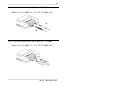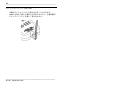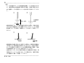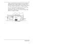
1
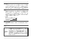
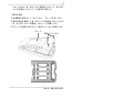
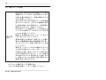
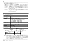
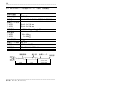
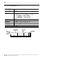
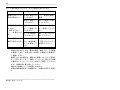
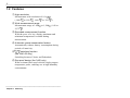
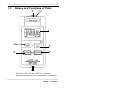
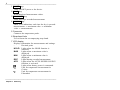
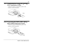
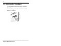
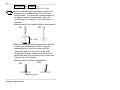
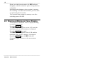
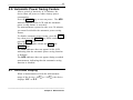
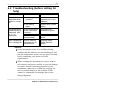
取扱説明書
Instruction Manual
3441
3442
温度ハイテスタ
TEMPERATURE
HiTESTER
2013年4月 発行 改訂12版
April 2013 Revised edition 12 3441A980-12 13-04H
目次
はじめに
1
点検
1
輸送上の注意
1
安全について
1
ご使用にあたっての注意
4
本書の構成と説明
6
第 1 章 概要
7
1.1 製品概要
1.2 特長
1.3 各部の名称と機能
第 2 章 仕様
2.1 一般仕様
2.2 環境条件
2.3 適合規格
7
8
9
11
11
13
13
第 3 章 測定を始める前に
15
3.1 電源の準備
3.2 温度プローブの接続
15
18
3.2.1 9180・9181・9182・9183
温度プローブの接続
3.2.2 9472・9473・9474・9475・9476
温度プローブの接続
3.3 ストラップバンドの取り付け
19
19
20
第 4 章 測定
4.1 電源の ON/OFF
4.2 測定について
4.3 表示ホールド
4.4 レコード測定
4.5 最高値・最低値表示
4.6 オートパワーセーブ機能
4.7 オーバーフロー表示
4.8 センサ断線表示
4.9 電池消耗表示
4.10 表示分解能の切換 第 5 章 センサ(オプション)
5.1 9180・9183 シース形温度プローブ (一般用)
5.2 9181 表面形温度プローブ
5.3 9182 シース形温度プローブ (高温用)
5.4 9472・9473 シース形温度プローブ
(一般用、 防滴構造)
5.5 9474・9475 シース形温度プローブ
(食品用、 防滴構造)
5.6 9476 表面形温度プローブ
第 6 章 保守・サービス
6.1 お手入れの方法
6.2 電池の交換
6.3 正常に動作しないとき、
および修理に出される前に
21
21
21
23
23
23
24
24
24
24
25
27
27
28
29
30
31
32
33
33
33
34
1
――――――――――――――――――――――――――
はじめに
このたびは、HIOKI“3441・3442 温度ハイテスタ ”をご選定
いただき、誠にありがとうございます。この製品を十分にご
活用いただき、末長くご使用いただくためにも、取扱説明書
はていねいに扱い、いつもお手元に置いてご使用ください。
点検
本器がお手元に届きましたら、輸送中において異常または破
損がないか点検してからご使用ください。特に付属品および、
パネル面のスイッチ、端子類に注意してください。万一、破
損あるいは仕様どおり動作しない場合は、お買上店(代理店)
か最寄りの営業所にご連絡ください。
○付属品
単 3 マンガン乾電池 (R6P)
ストラップバンド
取扱説明書
4
1
1
輸送上の注意
本器を輸送する場合は、お届けした時の梱包材料をご使用く
ださい。
安全について
警告
この機器は IEC 61010 安全規格に従って、設計さ
れ、試験し、安全な状態で出荷されています。測定
方法を間違えると人身事故や機器の故障につなが
る可能性があります。取扱説明書を熟読し、
十分に
内容を理解してから操作してください。万一事故
があっても、弊社製品が原因である場合以外は責
任を負いかねます。
―――――――――――――――――――――――
2
――――――――――――――――――――――――――
○安全記号
この取扱説明書には本器を安全に操作し、安全な状態に保つ
のに要する情報や注意事項が記載されています。本器を使用
する前に下記の安全に関する事項をよくお読みください。
・使用者は、機器上に表示されている
マークの
ところについて、取扱説明書の
マークの該当
箇所を参照し、機器の操作をしてください。
・使用者は、取扱説明書内の
マークのあるとこ
ろは、必ず読み注意する必要があることを示し
ます。
直流(DC)を示します。
取扱説明書の注意事項には、重要度に応じて以下の表記がさ
れています。
操作や取り扱いを誤ると、使用者が死亡または重
警告 傷につながる可能性があることを意味します。
操作や取り扱いを誤ると、使用者が傷害を負う場
注意 合、または機器を損傷する可能性があることを意
味します。
製品性能および操作上でのアドバイスを意味しま
注記 す。
○確度について
弊社では測定値の限界誤差を、次に示す rdg.(リーディング)
に対する値として定義しています。
・rdg. (読み値、表示値、指示値)
現在測定中の値、測定器が現在指示している値を表します。
―――――――――――――――――――――――
3
――――――――――――――――――――――――――
○測定カテゴリについて
測定器を安全に使用するため、IEC61010 では測定カテゴリ
として、使用する場所により安全レベルの基準を CATⅡ∼
CATⅣで分類しています。概要は次のようになります。
CATⅡ:コンセントに接続する電源コード付き機器(可搬形
工具・家庭用電気製品など)の一次側電路
コンセント差込口を直接測定する場合は CAT Ⅱで
す。
CATⅢ:直接分電盤から電気を取り込む機器(固定設備)の
一次側および分電盤からコンセントまでの電路
CATⅣ:建造物への引込み電路、引込み口から電力量メータ
および一次側電流保護装置(分電盤)までの電路
カテゴリの数値の小さいクラスの測定器で、数値の大きいク
ラスに該当する場所を測定すると重大な事故につながる恐れ
がありますので、絶対に避けてください。
カテゴリのない測定器で、CAT Ⅱ∼ CAT Ⅳの測定カテゴリ
を測定すると重大な事故につながる恐れがありますので、絶
対に避けてください。
―――――――――――――――――――――――
4
――――――――――――――――――――――――――
ご使用にあたっての注意
本器を安全にご使用いただくために、また機能を十二分にご
活用いただくために、下記の注意事項をお守りください。
○本器の設置について
使用温湿度範囲:0 ∼ 40 ℃、80%rh 以下(結露しないこと)
確度保証温湿度範囲:23 ± 5 ℃、80%rh 以下(結露しないこと)
本器の故障、事故の原因になりますので、次のような場所には設置しな
いでください。
直射日光があたる場
所
高温になる場所
腐食性ガスや爆発性ガ
スが八瀬逸する場所
水のかかる場所
多湿、結露するよう
な場所
強力な電磁波を発生す
る場所
帯電しているものの近
く
ほこりの多い場所
誘導加熱装置の近く
(高周波誘導加熱装置、
I H 調理器具など)
機械的振動の多い場
所
○使用前の点検
使用前には、保存や輸送による故障がないか、点検と動作確
認をしてから使用してください。故障を確認した場合は、お
買上店(代理店)か最寄りの営業所にご連絡ください。
警告
プローブの被覆が破れたり、金属が露出していな
いか、
使用する前に確認してください。損傷がある
場合は、感電事故になるので、弊社指定のものと交
換してください。
―――――――――――――――――――――――
5
――――――――――――――――――――――――――
注意
・本器は熱電対センサ(K タイプ)のみ使用可能で
す。他のセンサを接続したり、
センサ端子から電
圧信号を入力しないでください。本器を破損す
ることがあります。
・本器の使用環境および設置場所は使用温湿度範
囲 0 ∼40 、80% rh 以下の屋内です。
温度プローブの使用温度範囲については 5 章に
記載されている各プローブの仕様に従ってくだ
さい。
・3441 は防水、防塵構造となっていません。ホコ
リの多い環境や水のかかる環境下で使用しない
でください。故障の原因になります。
・3442 は防滴・防塵構造となっていますが、内部
へのホコリ、水滴の侵入を防ぐもので、完全防水
ではありません。故障の原因になりますので、
ぬ
れた状態では使用しないでください。
・本器に油などが付着したままの状態で長期間使
用すると、ケースの変形や破損につながります
ので注意してください。
・本器の汚れをとるときは、柔らかい布に水か中
性洗剤を少量含ませて、
軽く拭いてください。ベ
ンジン、アルコール、アセトン、エーテル、ケト
ン、シンナー、ガソリン系を含む洗剤は絶対に使
用しないでください。変形、
変色することがあり
ます。
・温度プローブのシースの中には酸化マグネシウ
ムの粉末が充填されています。万が一、
プローブ
が破損した場合、酸化マグネシウムの粉末が流
出する可能性がありますので、シースに過度な
力が加わらないように取り扱いにご注意くださ
い。酸化マグネシウム粉末を大量に摂取すると
健康を損なう恐れがあります。
―――――――――――――――――――――――
6
――――――――――――――――――――――――――
本書の構成と説明
第 1 章 概要
本器の概要と特長また本器の各部の名称および端子
や各キーの機能について説明してあります。
第 2 章 仕様
製品仕様について説明してあります。
第 3 章 測定を始める前に
センサ、電源の準備等について説明してあります。
第 4 章 測定
測定方法について説明してあります。
第 5 章 センサ
別売オプションの温度プローブについて説明してあ
ります。
第 6 章 保守
保守について説明してあります。
―――――――――――――――――――――――
7
――――――――――――――――――――――――――
第 1 章 概要
1.1 製品概要
3441・3442 温度ハイテスタは、熱電対センサ(K タイプ)を
使用して高分解能、広温度範囲の測定が可能な温度計です。
レコード測定機能により、測定中の最高温度および最低温度
を記憶することが可能です。また、3442 は防滴構造となって
いるため、専用の温度プローブと組み合わせて使用すること
により、水滴がかかるような環境での測定も可能となります
ので幅広い用途での温度測定に役立ちます。
―――――――――――――――――――――――
第 1 章 概要
8
――――――――――――――――――――――――――
1.2 特長
①高分解能
0.1 の高分解能で測定が可能(-100.0
∼199.9
)
②広い測定温度範囲
-100 ∼1300 までの広い範囲の温度測定が可能
③レコード測定機能
測定中に記憶した最高温度および最低温度を、キー操作で呼
び出して表示
④オートパワーセーブ機能
オートパワーセーブ機能により、電源の切り忘れによる電池
の消耗を防止
⑤防滴構造(3442 のみ)
専用の温度プローブと組み合わせて使用することにより防滴
構造となるため、水滴のかかるような場所でも安心して使用
が可能
―――――――――――――――――――――――
第 1 章 概要
9
――――――――――――――――――――――――――
1.3 各部の名称と機能
⑥ ⑤
⑦
①
②
④
③
⑥
―――――――――――――――――――――――
第 1 章 概要
10
――――――――――――――――――――――――――
各部の名称と機能は共通となっています。
3441 と 3442 では、
① POWER キー
本体の電源を ON/OFF します。
② HOLD キー
測定値をホールドします。
③ REC START キー
レコード測定をスタートまたはストップします。
④ MAX/MIN キー
キーを操作するごとに、LCD 表示を測定値→最高値→最低値
→測定値の順番で切り換えます。
⑤ コネクタ
温度プローブを接続します。
⑥ ストラップバンド取り付け穴
付属のストラップバンドを取り付けます。
⑦ LCD ディスプレイ
測定値および設定内容などの各種情報を表示します。
小数点
.
ホールド機能動作時に点灯
HOLD
最高値表示時に点灯
MAX
最低値表示時に点灯
MIN
レコード測定中に点灯
REC
オートパワーセーブ機能動作時に点灯
APS
電池消耗時に点灯
摂氏温度測定時の単位
―――――――――――――――――――――――
第 1 章 概要
11
――――――――――――――――――――――――――
第 2 章 仕様
2.1 一般仕様
センサ種類
熱電対(K)
測定範囲
-100∼1300
分解能
0.1
[-100.0∼199.9 ]
1 [200∼1300 ]
(オートレンジ切り替え)
本体確度
(23 ±5 )
確度保証期間6ヶ月の場合
(0.1%rdg.+0.8 ) [-100∼199.9
(0.2%rdg.+1 )
確度保証期間1年の場合
(0.15%rdg.+1.2 )
(0.3%rdg.+1.5 )
]
[200∼1300 ]
[-100∼199.9 ]
[200∼1300 ]
温度係数
0.03 / (-100∼199.9 )
0.05 / (200∼1300 )
サンプリング周期
0.5秒
表示
LCD表示
機能
REC(REC表示中は最高・最低値をメモリ)
MAX(REC測定中の最高値を表示)
MIN(REC測定中の最低値を表示)
HOLD(表示データのホールド)
バーンアウト(センサ断線表示:- - - -)
オーバーレンジ表示(O.F、-O.F)
―――――――――――――――――――――――
第 2 章 仕様
12
――――――――――――――――――――――――――
APS(オートパワーセーブ)
(電池消耗表示)
電源
単3形アルカリ乾電池(LR6×4)
単3形マンガン乾電池(R6P×4)
定格電源電圧 DC1.5V×4
最大定格電力
35 mVA
連続使用時間
約200時間(R6P×4使用)
寸法
約74W×155H×24D mm
(突起物およびプローブは含まず)
質量
約160 g(電池およびプローブは含まず)
付属品
単3形マンガン乾電池(R6P×4)
ストラップバンド
取扱説明書
オプション
9180
シース形温度プローブ(一般用)
[許容差:JIS クラス2]
9181
表面形温度プローブ
9182
シース形温度プローブ(一般用)
[許容差:JIS クラス2]
9183
シース形温度プローブ(高温用)
[許容差:JIS クラス1]
9472
シース形温度プローブ(一般用)
[許容差:JIS クラス1]
9473
シース形温度プローブ(高温用)
[許容差:JIS クラス1]
9474
シース形温度プローブ(食品用)
[許容差:JIS クラス1]
9475
シース形温度プローブ(食品用)
[許容差:JIS クラス1]
9476
表面形温度プローブ
9386-01 携帯用ケース
―――――――――――――――――――――――
第 2 章 仕様
13
――――――――――――――――――――――――――
2.2 環境条件
使用温湿度範囲
0∼40 、
80%rh以下(結露なきこと)
保存温湿度範囲
-10∼50
使用場所
屋内使用、汚染度2、高度2000 mまで
、
80%rh以下(結露なきこと)
2.3 適合規格
安全性
EN61010
EMC
EN61326
防滴構造
(3442のみ)
EN60529
IP54
―――――――――――――――――――――――
第 2 章 仕様
14
――――――――――――――――――――――――――
―――――――――――――――――――――――
第 2 章 仕様
15
――――――――――――――――――――――――――
第 3 章 測定を始める前に
本器の損傷を防ぐため、運搬および取り扱いの際
注意 は振動、衝撃を避けてください。特に、落下などに
よる衝撃に注意してください。本器を破損します。
3.1 電源の準備
・感電事故を避けるため、
電源 スイッチを OFF に
し、プローブを外してから電池を交換してくだ
さい。また交換後は必ず下ケースを取り付けて
使用してください。
警告
・電池交換するときは新旧および異種の混合はし
ないでください。また極性+−に注意し、
逆挿入
しないでください。性能劣化や液漏れの原因に
なります。
・使用済の電池をショート、分解または火中への
投入はしないでください。破裂する恐れがあり
危険です。
・使用済の電池は地域で定められた規則に従って
処分してください。
―――――――――――――――――――――――
第 3 章 測定を始める前に
16
――――――――――――――――――――――――――
・電池交換の際には下ケースをはずす必要があり
ます。下ケースは 2 本のネジで固定してありま
すので、電池交換の際にはネジをなくさないよ
うに注意してください。
注意
・3442 は、下ケースおよび固定ネジの部分にゴム
のリングが挿入してあります。電池交換などで
下ケースをはずした場合は、ゴムのリングを確
実に取り付けてあることを確認してから下ケー
スを固定してください。ゴムのリングが確実に
取り付けられていない場合は、防滴構造が保て
ず内部に水が侵入して本器の破損の原因となり
ます。
注記 電池の液漏れによる腐食を防ぐため、長い間使用しない
ときは、電池を抜いて保管してください。
―――――――――――――――――――――――
第 3 章 測定を始める前に
17
――――――――――――――――――――――――――
、単 3 形ア
3441・3442 は、単 3 形マンガン乾電池(R6P×4)
ルカリ乾電池(LR6×4)での使用が可能です。
○電池の実装
①本体裏面の固定ネジ(2 本)を外し、下ケースを外します。
②電池の極性を確認して単 3 形マンガン乾電池(R6P×4)また
は、単 3 形アルカリ乾電池(LR6×4)を実装します。
③下ケースを確実に取り付けて、固定ネジ(2 本)で固定します。
下ケース
固定ネジ(2 本)
―――――――――――――――――――――――
第 3 章 測定を始める前に
18
――――――――――――――――――――――――――
3.2 温度プローブの接続
・9180・9181・9182・9183・9476 温度プローブは防
滴構造となっていません。握り部およびコネク
タ部に水滴が付着すると、故障の原因になりま
すので注意してください。
・9472・9473・9474・9475 温度プローブは防滴構
造となっていますが、コネクタの金属端子部分
に水滴が付着したまま使用すると、測定誤差の
原因になりますので、注意してください。
・9474・9475 シース形温度プローブの先端はとが
っているため危険です。けがのないよう、
取り扱
いには十分注意してください。
注意
・断線による故障を防ぐため、プローブを折った
り引っ張ったりしないでください。
・高温の測定を行う場合は、温度プローブの握り
部および補償導線が指定の温度範囲(第 5 章 センサ(オプション)参照)を超えないよう注意
してください。
・温度プローブのシースの中には酸化マグネシウ
ムの粉末が充填されています。万が一、
プローブ
が破損した場合、酸化マグネシウムの粉末が流
出する可能性がありますので、シースに過度な
力が加わらないように取り扱いにご注意くださ
い。酸化マグネシウム粉末を大量に摂取すると
健康を損なう恐れがあります。
オプションの温度プローブを接続します。
コネクタの極性を確認して、正しく接続してください。
―――――――――――――――――――――――
第 3 章 測定を始める前に
19
――――――――――――――――――――――――――
3.2.1 9180・9181・9182・9183 温度プローブの接続
本体のコネクタに温度プローブのプラグを接続します。
赤
黒
3.2.2 9472・9473・9474・9475・9476 温度プローブの接続
本体のコネクタに温度プローブのプラグを接続します。
―――――――――――――――――――――――
第 3 章 測定を始める前に
20
――――――――――――――――――――――――――
3.3 ストラップバンドの取り付け
付属のストラップバンドを取り付けることができます。
本体の上部と下部の 2 箇所に穴がありますので、必要な箇所
にストラップバンドを通して取り付けます。
―――――――――――――――――――――――
第 3 章 測定を始める前に
21
――――――――――――――――――――――――――
第 4 章 測定
4.1 電源の ON/OFF
POWER キーを押します。
LCD 表示が 2 秒間全点灯した後、温度測定値を表示します。
再び POWER キーを押すと、表示が消え電源が切断されま
す。
4.2 測定について
測定するときは、次のページの注記を参考にしてください。
―――――――――――――――――――――――
第 4 章 測定
22
――――――――――――――――――――――――――
注記
・シース形温度プローブの測温部は金属シースの先端にありま
す。被測定物の内部温度を測定する場合、正確に測定するた
めに金属シースの直径の 15∼20 倍の長さを挿入してくださ
い。
○
×
内部温度
測定
15D∼20D
D
・表面形温度プローブで表面温度を測定する場合、正確に測定
するために測温部を十分に接触させてください。
(9181 表面
形温度プローブの場合、保護キャップをはずして測定してく
ださい)
○
×
測温部
表面温度
測定
・周囲温度が急激に変化する場所での使用は、基準接点補償が
不安定になり測定誤差の原因となりますので、本体と温度プ
ローブを接続した状態で 10∼20 分間使用環境に放置し、
本体
が周囲温度になじんでから測定を行ってください。
・本器の近くにモータなど磁界の発生する機器がある場合、測
定値がふらつくことがあります。その場合には、磁界を発生
する機器から離して設置してください。
―――――――――――――――――――――――
第 4 章 測定
23
――――――――――――――――――――――――――
4.3 表示ホールド
キー操作した時点の表示値をホールドします。
HOLD キーを押します。
表示ホールドしてい
LCD 表示部に HOLD マークが表示され、
ることを表します。
表示ホールドを解除する場合は、再び HOLD キーを押して
HOLD マークを消します。
4.4 レコード測定
レコード測定中の最高値および最低値を内部メモリに記憶し
ます。
REC START キーを押します。
LCD 表示部に REC マークが表示され、レコード測定をスタ
ートします。
レコード測定をストップする場合は、再び REC START キ
ーを押して REC マークを消します。
レコード測定中は、APS マークが消え、オートパワーセーブ
機能は解除されます。
レコード測定をストップした後も、最高値および最低値は記
憶されていますが、再びレコード測定をスタートした時点で
前回記憶したデータを消去し最新のデータに更新します。
電源を ON/OFF しても記憶したデータは消去されません。
4.5 最高値・最低値表示
レコード測定中の最高値または最低値を表示します。
MAX/MIN キーを押します。
LCD 表示部に MAX マークが表示され、内部メモリに記憶さ
れている最高値が表示されます。
再び MAX/MIN キーを押します。
内部メモリに記憶され
LCD 表示部に MIN マークが表示され、
ている最低値が表示されます。
再び MAX/MIN キーを押すと MIN マークが消えて測定値の
表示に戻ります。
―――――――――――――――――――――――
第 4 章 測定
24
――――――――――――――――――――――――――
4.6 オートパワーセーブ機能
最後にキー操作を行ってから、30 分経過すると自動的に電源
が OFF して電池の消耗を防ぎます。
POWER キーを押して電源を ON すると、LCD 表示部に
APS マークが表示され自動的にオートパワーセーブ機能が
働きます。
30 分以上の長時間の測定を行う場合は、オートパワーセーブ
機能を解除して使用します。
オートパワーセーブ機能を解除する場合は、電源 ON する際
に HOLD キーを押しながら POWER キーを押します。
LCD 表示が点灯したら HOLD および POWER キーを放し
ます。
LCD 表示部には APS マーク表示されず、オートパワーセー
ブ機能が解除された状態となります。
レコード測定中は、APS マークが消え、オートパワーセーブ
機能は解除されます。
4.7 オーバーフロー表示
測定温度が本器の測定範囲(-100 ∼1300
合、-O.F または O.F が表示されます。
)から外れた場
4.8 センサ断線表示
センサが接続されていない場合、またはセンサが断線してい
る場合、- - - - が表示されます。
注記 温度プローブを正しく接続しても - - - - が表示される場
合は、センサの断線が考えられます。
センサ断線の簡易的な確認方法として、テスタなどを利
用して温度プローブの端子間の抵抗を測定し、抵抗値が
大きい場合には断線が考えられます。
4.9 電池消耗表示
マーク点灯時は、電池が消耗していますので、早めに交換
してください。
―――――――――――――――――――――――
第 4 章 測定
25
――――――――――――――――――――――――――
4.10 表示分解能の切換 189.9 以下の温度から上昇する場合は、199.9 から 200
で表示分解能を自動的に切り換えます。 200 以上の温度から下降する場合は、190 から 189.9 で
表示分解能を自動的に切り換えます。
―――――――――――――――――――――――
第 4 章 測定
26
――――――――――――――――――――――――――
―――――――――――――――――――――――
第 4 章 測定
27
――――――――――――――――――――――――――
第 5 章 センサ(オプション)
5.1 9180・9183 シース形温度プローブ(一般用)
素線の種類
K
接点の種類
非接地形
許容差
(9180)
(9183)
JIS C 1602 クラス2(旧階級 0.75級)
JIS C 1602 クラス1(旧階級 0.4級)
金属シース寸法 約φ3.2×150 mm
補償導線
一般用(-20
測定温度
-50∼750
握り部耐熱
150
∼90 )約1 m
金属シース材質 SUS 316
耐電圧
AC500 V 1分間
絶縁抵抗
100 MΩ以上(DC100 V)
補償導線
1000
握り部
100
金属シース
測温部
φ3.2×150
―――――――――――――――――――――――
第 5 章 センサ(オプション)
28
――――――――――――――――――――――――――
注記 熱電対の許容差について
温度プローブに使用している熱電対は、J IS C 1602-1995 に
規定されているクラス 1 またはクラス 2 相当のものを使用し
ています。許容差については以下の値を参考としてください。
クラス 1:-40 以上で±1.5 または測定温度の±0.4%のど
ちらか大きい値
クラス 2:-40 以上で±2.5 または測定温度の±0.75%の
どちらか大きい値
5.2 9181 表面形温度プローブ
素線の種類
K
接点の種類
接地形
測定確度
±2.5 [(T-Ts)≦100 ]
-0.035×T ∼+2.5 [100 <(T-Ts)]
T :測定温度(-50 ∼400 )
Ts:周囲温度( 0 ∼50 )
測温部寸法
約φ13 mm
補償導線
一般用(-20
測定温度
-50∼400
握り部耐熱
150
補償導線
∼90 )約1 m
握り部
測温部φ13
キャップ
1000
110
注記 表面形温度プローブでは、測温部の熱容量ができるだけ
小さくなるように設計されていますが、プローブを接触
させることによる放熱などの影響により、真の表面温度
に対して誤差が大きくなることがあります。
―――――――――――――――――――――――
第 5 章 センサ(オプション)
29
――――――――――――――――――――――――――
5.3 9182 シース形温度プローブ(高温用)
素線の種類
K
接点の種類
非接地形
許容差
JIS C 1602 クラス2(旧階級 0.75級)
シース部寸法
約φ3.2×500 mm
補償導線
耐熱用(-0 ∼150 )約2 m
測定温度
-50∼750
フランジ部耐熱 90
保護管材質
INCONEL
耐電圧
AC500 V 1分間
絶縁抵抗
100 MΩ以上(DC100 V)
フランジ 金属シース
補償導線
2000
55
30
測温部
φ3.2×500
―――――――――――――――――――――――
第 5 章 センサ(オプション)
30
――――――――――――――――――――――――――
5.4 9472・9473 シース形温度プローブ(一般用、防滴構造)
素線の種類
K
接点の種類
非接地形
許容差
JIS C 1602 クラス1(旧階級 0.4級相当)
金属シース寸法
約φ2.3×150 mm
(9472)
約φ4.8×300 mm
(9473)
補償導線
一般用(-20
測定温度
(9472)
(9473)
-100∼300
0∼800
握り部耐熱
80
∼90 )約1 m
金属シース材質 SUS 316
耐電圧
AC500 V 1分間
絶縁抵抗
100 MΩ以上(DC500 V)
補償導線
1000
握り部
100
金属シース
測温部
φ2.3×150
φ4.8×300
―――――――――――――――――――――――
第 5 章 センサ(オプション)
31
――――――――――――――――――――――――――
5.5 9474・9475 シース形温度プローブ(食品用、防滴構造)
素線の種類
K
接点の種類
非接地形
許容差
JIS C 1602 クラス1(旧階級 0.4級相当)
金属シース寸法
約φ2.3×100 mm
(9474)
約φ4.8×100 mm
(9475)
補償導線
一般用(-20
測定温度
(9474)
(9475)
-100∼300
-100∼500
握り部耐熱
80
∼90 )約1 m
金属シース材質 SUS 316
耐電圧
AC500 V 1分間
絶縁抵抗
100 MΩ(DC500 V)
補償導線
1000
握り部
100
金属シース
測温部
φ2.3×100
φ4.8×100
―――――――――――――――――――――――
第 5 章 センサ(オプション)
32
――――――――――――――――――――――――――
5.6 9476 表面形温度プローブ
素線の種類
K
接点の種類
接地形
測定確度
±2.5 [(T-Ts)≦100 ]
-0.03×T ∼+2.5 [100 <(T-Ts)]
T :測定温度(-40 ∼500 )
Ts:周囲温度( 0 ∼40 )
測温部寸法
約φ20 mm
補償導線
一般用(-20
測定温度
-40∼500
握り部耐熱
80
∼90 )約1 m
握り部
補償導線
測温部
1000
100
90
25
―――――――――――――――――――――――
第 5 章 センサ(オプション)
33
――――――――――――――――――――――――――
第 6 章 保守・サービス
6.1 お手入れの方法
注意
本器の汚れをとるときは、柔らかい布に水か中性
洗剤を少量含ませて、
軽く拭いてください。ベンジ
ン、アルコール、アセトン、エーテル、ケトン、シ
ンナー、ガソリン系を含む洗剤は絶対に使用しな
いでください。変形、変色することがあります。
6.2 電池の交換
警告
・電池交換するときは新旧および異種の混合はし
ないでください。また極性+−に注意し、
逆挿入
しないでください。性能劣化や液漏れの原因に
なります。
・使用済の電池をショート、分解または火中への
投入はしないでください。破裂する恐れがあり
危険です。
・使用済の電池は地域で定められた規則に従って
処分してください。
マーク点灯時は、電池が消耗していますので、早めに交換
してください。
。
マークが点灯した状態で、さらに継続して使用した場合は
自動的に電源が OFF になる場合があります。
(電池の交換方法については 3.1 参照)
―――――――――――――――――――――――
第 6 章 保守・サービス
34
――――――――――――――――――――――――――
6.3 正常に動作しないとき、および修理に出される前に
症 状
原 因
対 策
電源を ON しても 電 池 が 実 装 さ れ 「3.1 電源の準備」
表示が現れない
ていますか?
参照
電池 が消耗 して 新しい電池と交換
いませんか?
してください
温度測定値が表示
されない
( O.F または
- - - - が表示され
る)
温度 プロー ブが 温度プローブを正
正し く接続 され しく接続してくだ
ていますか?
さい
E92 が表示される
E97 が表示される
何 ら か の 要 因 に 修理が必要です
より、本体内蔵メ (下記「サービス」を
モ リ が 故 障 し て お読みください)
いる
セン サが断 線し 新しいセンサに交
ていませんか?
換してください
○サービス
・故障と思われるときは、電池の消耗、温度 プローブの断線
を確認してから、お買上店(代理店)か最寄りの営業所に
ご連絡ください。
・修理に出される場合は、輸送中に破損しないように電池を
すべて取り外してから、梱包してください。箱の中で本器
が動かないように、クッション材などで固定してください。
また、故障内容も書き添えてください。
輸送中の破損については保証しかねます。
・本器の確度維持あるいは確認には、定期的な校正が必要で
す。
―――――――――――――――――――――――
第 6 章 保守・サービス
3441,3442
3441
3441-02
3442
TEMPERATURE
HiTESTER
INSTRUCTION MANUAL
Contents
Introduction
Inspection
Shipping the Instrument
Safety Notes
Notes on Use
Organization of this Manual
Chapter 1 Summary
1.1 Product Summary
1.2 Features
1.3 Names and Functions of Parts
Chapter 2 Specification
2.1 General Specification
2.2 Environmental Conditions
2.3 Applicable Standards
Chapter 3 Before Measurement
3.1 Preparations for the Batteries
3.2 Connecting the Temperature Probe
i
i
ii
ii
vi
viii
1
1
2
3
5
5
8
8
9
9
12
3.2.1 Connecting the 9180 9181 9182 9183
13
Temperature Probe
3.2.2 Connecting the 9472 9473 9474 9475
9476 Temperature Probe
13
3.3 Attaching the Strap Band
14
Chapter 4 Measurement
4.1 Turning ON/OFF
4.2 Switching Celsius/Fahrenheit
(the 3441-02 only)
4.3 Display Hold
4.4 Recorded Measurement
4.5 Maximum/Minimum Value Display
4.6 Automatic Power Saving Feature
4.7 Overflow Display
4.8 Sensor Disconnection Display
4.9 Battery Consumption Display
4.10 Switching the display resolution
Chapter 5 Sensor (Options)
15
15
15
17
17
18
19
19
20
20
20
21
5.1 9180 9183 SHEATH TYPE TEMPERATURE
PROBE (for general)
21
23
5.2 9181 SURFACE TEMPERATURE PROBE
5.3 9182 SHEATH TYPE TEMPERATURE
PROBE (for high temperature)
24
5.4 9472 9473 SHEATH TYPE TEMPERATURE
PROBE (for general, drip-proof)
25
5.5 9474 9475 SHEATH TYPE TEMPERATURE
PROBE (for food, drip-proof)
26
5.6 9476 SURFACE TYPE TEMPERATURE
PROBE
27
Chapter 6 Maintenance and Service
6.1 Changing the Batteries
6.2 Troubleshooting (before calling for help)
29
30
31
___________________________________________i
Introduction
Thank you for purchasing the HIOKI "3441, 344102, 3442 TEMPERATURE HiTESTER." To obtain
maximum performance from the instrument, please
read this manual first, and keep it handy for future
reference.
Inspection
When you receive the instrument, inspect it
carefully to ensure that no damage occurred during
shipping. In particular, check the accessories, panel
switches, and connectors. If damage is evident, or if
it fails to operate according to the specifications,
contact your dealer or Hioki representative.
Supplied accessories
R6P manganese batteries
Strap band
Instruction manual
4
1
1
___________________________________________
Introduction
ii
___________________________________________
Shipping the Instrument
Use the original packing materials when reshipping
the instrument, if possible.
Safety Notes
WARNING
This instrument is designed to conform to IEC
61010 Safety Standards, and has been thoroughly
tested for safety prior to shipment. However,
mishandling during use could result in injury or
death, as well as damage to the instrument. Be
certain that you understand the instructions and
precautions in the manual before use. We
disclaim any responsibility for accidents or
injuries not resulting directly from instrument
defects.
Safety symbols
This manual contains information and warnings
essential for safe operation of the instrument and for
maintaining it in safe operating condition. Before
using the instrument, be sure to carefully read the
following safety notes.
___________________________________________
Shipping the Instrument
iii
___________________________________________
The
symbol printed on the
instrument indicates that the user
should refer to a corresponding topic
in the manual (marked with the
symbol) before using the relevant
function.
In the manual, the
symbol indicates
particularly important information that
the user should read before using the
instrument.
Indicates DC (Direct Current).
The following symbols in this manual indicate the
relative importance of cautions and warnings.
WARNING
Indicates that incorrect operation
presents a significant hazard that could
result in serious injury or death to the
user.
CAUTION
Indicates that incorrect operation
presents a possibility of injury to the
user or damage to the instrument.
NOTE
Indicates advisory items related to
performance or correct operation of the
instrument.
___________________________________________
Safety Notes
iv
___________________________________________
Accuracy
We define measurement tolerances in terms of rdg.
(reading) values, with the following meanings:
rdg. (displayed or indicated value)
This signifies the value actually being measured,
i.e., the value that is currently indicated or displayed
by the measuring instrument.
Measurement categories
To ensure safe operation of measurement
instruments, IEC 61010 establishes safety standards
for various electrical environments, categorized as
CAT II to CAT IV, and called measurement
categories. These are defined as follows.
CAT II: Primary electrical circuits in equipment
connected to an AC electrical outlet by a
power cord (portable tools, household
appliances, etc.)
CAT II covers directly measuring electrical
outlet receptacles.
CAT III: Primary electrical circuits of heavy
equipment (fixed installations) connected
directly to the distribution panel, and
feeders from the distribution panel to
outlets.
CAT IV: The circuit from the service drop to the
service entrance, and to the power meter
and primary overcurrent protection device
(distribution panel).
___________________________________________
Safety Notes
v
___________________________________________
Using a measurement instrument in an environment
designated with a higher-numbered category than
that for which the instrument is rated could result in
a severe accident, and must be carefully avoided.
Use of a measurement instrument that is not CATrated in CAT II to CAT IV measurement
applications could result in a severe accident, and
must be carefully avoided.
___________________________________________
Safety Notes
vi
___________________________________________
Notes on Use
Follow these precautions to ensure safe operation and
to obtain the full benefits of the various functions.
Setting up the Instrument
Operating temperature and humidity:
0 to 40°C (32 ± 122°F), 80%RH or less (non-condensating)
Temperature and humidity range for guaranteed accuracy:
23 ± 5°C (73 ± 9°F), 80% RH or less (non-condensating)
Avoid t he following locations t h a t could cause a n accident or da ma ge
to t he inst r ument .
Exposed to direct
sunlight
Exposed to high
temperature
In the presence of
corrosive or explosive
gases
Exposed to liquids
Exposed to high
humidity or
condensation
Exposed to strong
electromagnetic fields
Near electromagnetic
radiators
Exposed to high
levels of particulate
dust
Near induction heating
systems
(e.g., high-frequency
induction heating
Subject to vibration
Preliminaly Checks
Before using the instrument the first time, verify
that it operates normally to ensure that the no
damage occurred during storage or shipping. If you
find any damage, contact your dealer or Hioki
representative.
___________________________________________
Notes on Use
vii
___________________________________________
WARNING
Before using the instrument, make sure that the insulation
on the test leads and probes is undamaged and that no
bare conductors are improperly exposed. Using the
product in such conditions could cause an electric shock,
so contact your dealer or Hioki representative for
replacements.
CAUTION
This device is intended solely for use with thermocouple
sensors (K type). To avoid damage, do not connect it to
any other type of sensor. Do not input a voltage signal
from the sensor terminal.
This instrument should be installed and operated indoors
only, between 0 to 40 (32 to 104 ) and 80% RH. The
operational temperature range for the temperature probe
is provided in the specifications given in Chapter 5.
The 3441, 3441-02 is not designed to be entirely water- or
dust-proof. To avoid damage, do not use it in a wet or
dusty environment.
Although this 3442 is designed to resist the ingress of
dust and water, it is not entirely water- or dust-proof, so
to avoid shock or damage, do not use it in a wet or dusty
environment.
Please be aware that direct contact of the instrument to oil
and other substances for a long period of time may cause
deformation of the case or damage to the instrument.
To clean the instrument, wipe it gently with a soft cloth
moistened with water or mild detergent. Never use
solvents such as benzene, alcohol, acetone, ether,
ketones, thinners or gasoline, as they can deform and
discolor the case.
The sheath of the temperature probe is filled with
magnesium oxide powder. If the probe is broken, the
magnesium oxide powder may spill out. Be carefulnot to
subject the sheath to excess stress. Inhaling large
quantities of magnesium oxide may be hazardous to your
health.
___________________________________________
Notes on Use
viii
___________________________________________
Organization of this Manual
Chapter 1
Summary
Provides an outline and describes device
characteristics, as well as part names and terminal
and key functions.
Chapter 2
Specification
Provides device specifications.
Chapter 3
Before Measurement
Describes preparation of sensor and power source.
Chapter 4
Measurement
Describes measurement procedures.
Chapter 5
Sensor (Options)
Describes the optional temperature probe.
Chapter 6
Maintenance and Service
Describes maintenance procedures.
___________________________________________
Organization of this Manual
1
___________________________________________
Chapter 1
Summary
1.1 Product Summary
Used with a thermocouple (K type), the 3441, 344102 and 3442 HiTESTER thermometers provide
high-resolution measurements across a wide range of
temperatures. A recorded measurement function
permits recording of maximum and minimum
temperatures. With its drip-proof design, the 3442
offers extended versatility, allowing use in moistureprone environments when used with a specialpurpose temperature probe.
___________________________________________
Chapter 1 Summary
2
___________________________________________
1.2 Features
① High resolution
Measurement with resolution of 0.1 ( )
(-100.0 to 199.9 , -148.0 to 391.9 ).
② Wide measurement range
Measurement range of -100 to 1,300
2,372 ).
(-148 to
③ Recorded measurement function
With the press of a key, display maximum and
minimum temperatures recorded during
measurement.
④ Automatic power-conservation feature
Automatically reduces battery consumption during
periods of inactivity.
⑤
/ switching function
(the 3441-02 only)
Switching between Celsius and Fahrenheit.
⑥ Drip-proof design (the 3442 only)
Water-resistant when used with the single-purpose
temperature probe, enabling use in high-humidity
environments.
___________________________________________
Chapter 1 Summary
3
___________________________________________
1.3
Names and Functions of Parts
⑥
⑤
7
①
②
④
③
6
The 3441, 3441-02 and 3442 have identical
functions and names for corresponding components.
___________________________________________
Chapter 1 Summary
4
___________________________________________
1 POWER key
Turns ON/OFF power to the device.
2 HOLD key
Holds displayed measurement values.
3 REC START key
Starts and stops recorded measurement.
4 MAX/MIN key
Shifts LCD indications each time the key is pressed:
measurements → maximum value → minimum
value → measurements.
5 Connector
Connects the temperature probe.
6 Strap-band hole
Use to fasten the accompanying strap band.
7 LCD display
Displays information for measurements and settings.
.
Decimal point
HOLD Lights when the HOLD function is
activated.
MAX
Lights when a maximum value is
displayed.
MIN
Lights when a minimum value is
displayed.
REC
Lights during recorded measurement.
APS
Lights when the AUTO POWER SAVING
function is activated.
Lights when battery power is consumed.
Unit for temperature measurement in
Celsius.
Unit for temperature measurement in
Fahrenheit.
___________________________________________
Chapter 1 Summary
5
___________________________________________
Chapter 2
Specification
2.1 General Specification
Measurement Sensor
Thermocouple, K type
Measurement Range
-100 to 1300 , -148 to 2372
Resolution
0.1 [-100.0 to 199.9 ]
1
[200 to 1300 ]
0.1 [-148.0 to 391.9 ]
1
[392 to 2372 ]
AUTO RANGE
Accuracy
(23
5 )
(73
9 )
Period of Guaranteed Accuracy:
6 months
(0.1%
(0.1%
(0.2%
(0.2%
rdg.+0.8 )
rdg.+1.4 )
rdg.+1 )
rdg.+1.8 )
[-100.0
[-148.0
[200 to
[392 to
to 199.9 ]
to 391.9 ]
1300 ]
2372 ]
Period of Guaranteed Accuracy:
1 year
(0.15% rdg.+1.2
(0.15% rdg.+2.1
(0.3% rdg.+1.5
(0.3% rdg.+2.7
Temperature
Coefficient
0.03
0.05
0.05
0.09
Sampling Time
0.5s
Display
LCD
/
/
/
/
) [-100.0 to 199.9 ]
) [-148.0 to 391.9 ]
) [200 to 1300 ]
) [392 to 2372 ]
[-100 to 199.9 ]
[200 to 1300 ]
[-148.0 to 391.9 ]
[392 to 2372 ]
___________________________________________
Chapter 2 Specification
6
___________________________________________
Functions
REC (Displayed when maximum and
minimum values are being
recorded.)
MAX (Displays the maximum value
during REC measurement.)
MIN (Displays the minimum value
during REC measurement.)
HOLD (Keeps data on-screen.)
Burnout (Sensor disconnection
indication: ----)
Outside-range display (0.F, -0.F)
APS (Automatic Power Saving)
(Battries low warning)
Power source
LR6 alkaline battery x 4
R6P manganese battery x 4
Rated supply voltage 1.5 V DC x 4
Maximum rated power
35mVA
Continuous operating
time
Approx.200 hours
(R6P manganese battery x 4)
Dimensions
Approx.74W x 155H x 24D mm
Approx.2.91W" x 6.10H" x 0.94D"
(except for the projection and the
probe)
Mass
Approx. 160 g
Approx. 5.6 oz.
(except for the batteries and the
probe )
Accessories
R6P manganese battery x 4
Strap band
Instruction manual
Options
9180
SHEATH TYPE TEMPERATURE
PROBE (for general)
[Limit deviation tolerance:
2.5 ( 4.5 ) or 0.75% rdg.
whichever is greater.]
___________________________________________
Chapter 2 Specification
7
___________________________________________
9181
SURFACE TEMPERATURE PROBE
9182
SHEATH TYPE TEMPERATURE
PROBE (for general)
[Limit deviation tolerance:
2.5 ( 4.5 ) or 0.75% rdg.
whichever is greater.]
9183
SHEATH TYPE TEMPERATURE
PROBE (for High-Temperature)
[Limit deviation tolerance:
1.5 ( 2.7 ) or 0.4% rdg.
whichever is greater.]
9472
SHEATH TYPE TEMPERATURE
PROBE (for general)
[Limit deviation tolerance:
1.5 ( 2.7 ) or 0.4% rdg.
whichever is greater.]
9473
SHEATH TYPE TEMPERATURE
PROBE (for High-Temperature)
[Limit deviation tolerance:
1.5 ( 2.7 ) or 0.4% rdg.
whichever is greater.]
9474
SHEATH TYPE TEMPERATURE
PROBE (for food)
[Limit deviation tolerance:
1.5 ( 2.7 ) or 0.4% rdg.
whichever is greater.]
9475
SHEATH TYPE TEMPERATURE
PROBE (for food)
[Limit deviation tolerance:
1.5 ( 2.7 ) or 0.4% rdg.
whichever is greater.]
9476
SURFACE TEMPERATURE PROBE
9386-01 CARRYING CASE
___________________________________________
Chapter 2 Specification
8
___________________________________________
2.2 Environmental Conditions
Operating temperature 0 to 40 ,
and humidity range
32 to 104 ,
80%RH or less (no condensation)
Storage temperature
and humidity range
-10 to 50 ,
14 to 122 ,
80% RH or less (no condensation)
Location for use
Indoor,Pollution Degree 2
altitude up to 2000 m (6562 feet)
2.3 Applicable Standards
Safety
EN61010
EMC
EN61326
Waterproof
(the 3442 only)
EN60529
IP54
___________________________________________
Chapter 2 Specification
9
___________________________________________
Chapter 3
Before Measurement
CAUTION
To avoid damage to the instrument, protect it from
vibration or shock during transport and handling, and
be especially careful to avoid dropping.
3.1 Preparations for the Batteries
WARNING
To avoid electrocution, turn off the power
switch and disconnect the probes before
removing the lithium battery. After replacing the
batteries, replace the lower case and screws
before using the instrument.
Do not mix old and new batteries, or different
types of batteries. Also, be careful to observe
battery polarity during installation. Otherwise,
poor performance or damage from battery
leakage could result.
___________________________________________
Chapter 3 Before Measurement
10
___________________________________________
WARNING
To avoid the possibility of explosion, do not
short circuit, disassemble or incinerate
batteries.
Handle and dispose of batteries in accordance
with local regulations.
CAUTION
To replace the battery, remove the lower case.
The lower case is secured with two screws. Take
care to avoid misplacing screws during battery
replacement.
The 3442 has rubber rings furnished in the lower
case and on the fastening screws. After removing
the lower case for battery replacement, make sure
the rubber rings are firmly in place before closing
the case. Improper seating of a rubber ring will
permit passage of moisture into the device and
damage it.
NOTE
To avoid corrosion from battery leakage, remove the
batteries from the instrument if it is to be stored for
a long time.
___________________________________________
Chapter 3 Before Measurement
11
___________________________________________
The 3441, 3441-02 and 3442 are intended for use
with R6P manganese battery (R6P x 4) or LR6
alkaline battery (LR6 x 4) dry cells.
○ Battery Installation
1. Remove the two fastening screws at the back of the
device. Remove the lower case.
2. Check the polarity of the battery. Install R6P
manganese battery (R6P x 4) or LR6 alkaline
battery (LR6 x 4) dry cells.
3. Close the lower caseφ and secure with the two
fastening screws.
Lower case
Two fastening screws
___________________________________________
Chapter 3 Before Measurement
12
___________________________________________
3.2 Connecting the Temperature Probe
CAUTION
The 9180, 9181, 9182, 9183, and 9476
temperature probes are not drip-proof. Water
droplets on the grip or connector may result in
malfunctions.
The 9472, 9473, 9474, and 9475 have a drip-proof
design. However, droplets occurring on the metal
terminal of the connector may cause measurement
errors.
The ends of the 9474 and 9475 sheath type
temperature probes are sharp. Be careful to avoid
injury.
To avoid breaking the probes, do not bend or pull
them.
When measuring high temperatures, do not let the
grip of the temperature probe or the compensation
lead wire exceed the temperature range (Chapter
5: Sensor (Options)).
The sheath of the temperature probe is filled with
magnesium oxide powder. If the probe is broken,
the magnesium oxide powder may spill out. Be
carefulnot to subject the sheath to excess stress.
Inhaling large quantities of magnesium oxide may
be hazardous to your health.
Connect the optional probe.
Check the polarity of the connector, and connect
correctly.
___________________________________________
Chapter 3 Before Measurement
13
___________________________________________
3.2.1 Connecting the 9180 9181 9182
9183 Temperature Probe
Connect the plugs of temperature probe to the
connector of the instrument.
Red
Black
3.2.2 Connecting the 9472 9473 9474
9475 9476 Temperature Probe
Connect the plugs of temperature probe to the
connector of the instrument.
___________________________________________
Chapter 3 Before Measurement
14
___________________________________________
3.3 Attaching the Strap Band
The accompanying strap band may be attached to
the device.
A small hole is provided for the band at the head
and tail of the device.
___________________________________________
Chapter 3 Before Measurement
15
___________________________________________
Chapter 4
Measurement
4.1 Turning ON/OFF
Press the POWER key.
The LCD will light for two seconds before a
temperature measurement is displayed.
Press the POWER key again to turn off power.
4.2 Switching Celsius/Fahrenheit
(the 3441-02 only)
Temperature display may be switched between
Celsius and Fahrenheit.
At shipment, the device is preset to the Celsius
scale.
To measure in Fahrenheit, press the
REC START key, then power on while continuing to
hold the REC START key.
When the LCD lights, release both the
REC START and POWER keys.
for Fahrenheit.
The LCD displays an
Once made, the Fahrenheit setting remains in effect
even if the device is powered off.
To restore the Celsius display, press the POWER
key while pressing the REC START key.
= x 9/5+32
When the LCD lights, release both the
___________________________________________
Chapter 4 Measurement
16
___________________________________________
NOTE
REC START and POWER keys.
The LCD displays a
indicator for Celsius.
With the sheath type temperature probe, the
temperature is measured at the end of the
metal sheath. For accurate measurements of
an objects internal temperature, insert the
metal sheath to a depth of 15 to 20 times its
diameter.
Measurement of an objects internal temperature
OK
NO
15D∼20D
D
When measuring surface temperature with the
surface type temperature probe, bring the
measuring point into full contact with the
measured object (In the case of the 9181
temperature probe, measurement should be
performed after the protective cap is removed
from the tip of the probe).
Measurement of surface temperature
OK
NO
Measuring point
___________________________________________
Chapter 4 Measurement
17
___________________________________________
NOTE
Sudden changes in ambient temperature can
make the reference contact compensation
temperature highly unstable. Before use in
such environments, leave the device connected
to the temperature probe at operating
temperatures for 10 to 20 minutes to acclimate
it to the ambient temperature.
Measurements may fluctuate when
measurements are taken close to equipment
that generates magnetic fields, such as motors.
If this occurs, move the device away from
such equipment.
4.3 Display Hold
Used to hold the displayed value.
Press the HOLD key.
The HOLD indicator is displayed on the LCD to
indicate that the displayed value is being held.
To cancel Display Hold, press the HOLD key again.
The HOLD indication should disappear.
4.4 Recorded Measurement
Maximum and minimum recorded values during
recorded measurement are saved in internal memory.
Press the REC START key.
The REC indicator appears on the LCD, and
recorded measurement begins.
To stop measurement, press the REC START key
again. The REC indicator disappears.
___________________________________________
Chapter 4 Measurement
18
___________________________________________
During recorded measurement, the APS indicator
disappears, and the automatic power saving function
is disabled.
Maximum and minimum values remain in memory.
On resuming a recorded measurement, previous data
is replaced by the latest data.
The recorded data remains in memory even after
switching power ON/OFF.
4.5 Maximum/Minimum Value Display
A maximum or minimum value is displayed during
recorded measurement.
Press the MAX/MIN key.
The MAX indicator appears on the LCD, and the
maximum value saved in memory is displayed.
Press the MAX/MIN key again.
The MIN indicator appears on the LCD, and the
minimum value saved in memory is displayed.
Press the MAX/MIN key, the MIN indicator
disappears, again to return to the measurement
screen.
___________________________________________
Chapter 4 Measurement
19
___________________________________________
4.6 Automatic Power Saving Feature
After a period of inactivity of 30 minutes, the
device shuts off power to reduce battery power
consumption.
Press the POWER key to turn on power. The APS
indicator appears on the LCD, and the automatic
power saving feature is activated.
For measurements expected to take over 30 minutes,
you must first disable the automatic power saving
feature.
To disable automatic power saving, press the HOLD
key, then press the POWER key while continuing to
press the HOLD key.
When the LCD lights, release the HOLD and
POWER keys.
The APS indicator does not appear on the LCD,
indicating that the automatic power saving function
is disabled.
The APS indicator does not appear during recorded
measurement, indicating that the automatic saving
function is disabled.
4.7 Overflow Display
When a measurement exceeds the measurement
range of the device (-100 to 1,300 ), the device
displays -O.F. or O.F.
___________________________________________
Chapter 4 Measurement
20
___________________________________________
4.8 Sensor Disconnection Display
If the sensor has not been turned on or if it is
disconnected, the indication ---- is displayed.
NOTE
If the indication ---- is displayed even when the
temperature probe is on, a loose connection is
the likely cause. To check for a disconnection,
use a tester to measure the resistance between
the terminals on the temperature probe. An
excessively high resistance may indicate a
disconnection.
4.9 Battery Consumption Display
The
indicator appears when battery voltage
becomes low. Replace the batteries as soon as
possible.
4.10 Switching the display resolution
If the temperature rises from 189.9 (373.9 ) or
below, the display resolution will automatically
switch over when the temperature enters the range
from 199.9 (391.9 ) to 200 (392 ).
If the tempearture falls from -200 (392 ) or
more, the display resolution will automatically
switch over when the temperature enters the range
from 190 (374 ) to 189.9 (373.9 ).
___________________________________________
Chapter 4 Measurement
21
___________________________________________
Chapter 5
Sensor (Options)
5.1 9180 9183 SHEATH TYPE
TEMPERATURE PROBE (for
general)
Thermocouple
Material
K
Contact Type
Isolated Junction (ungrounded)
Accuracy
(9180)
2.5 (
whichever
(9183) 1.5 (
whichever
4.5 ) or
is greater.
2.7 ) or
is greater.
0.75% rdg.
0.4% rdg.
Dimensions (sheath)
Approx. φ 3.2 x 150 mm
Approx. φ 0.13" x 5.9"
Compensation Lead
Conventional type
(-20 to 90 , -4 to 194 ),
Approx. 1 m, 39.4"
Operating
Temperature
-50 to 750
-58 to 1382
Allowable Heat
(Handle)
150
302
Protective Shield
Material
SUS 316
Dielectric Strength
500 VAC for 1 minute
Insulation Resistance
100 MΩ or more (100 VDC)
___________________________________________
Chapter 5 Sensor (Options)
22
___________________________________________
Compensation lead
1000 (39.4")
NOTE
Handle
100 (3.94")
Sheath
Measuring
point
φ3.2x150
(φ0.13"x5.9")
Thermocouple Allowance
The thermocouple used in the temperature
probe complies with specifications for Class 1
and Class 2 provided in IEC 584. For the
permitted tolerances, refer to the following:
Class 1: At -40 (-40 ) and more, the greater
of 1.5 ( 2.7 ) and 0.4% of the
measured value.
Class 2: At -40 (-40 ) and more, the greater
of 2.5 ( 4.5 ) and 0.75% of
the measured value.
___________________________________________
Chapter 5 Sensor (Options)
23
___________________________________________
5.2 9181 SURFACE TEMPERATURE
PROBE
Thermocouple
Material
K
Contact Type
Grounded
Measurement
Accuracy
2.5 ( 4.5 )
(T-Ts) 100 (180 )
-0.035xT to +2.5 (4.5 )
100 (180 )<(T-Ts)
T :Measurement temp erature
(-50 to 400 /-58 to 752
Ts:Surroundings temp erature
(0 to 50 /32 to 122 )
Dimensions
(Measuring point)
)
Approx. φ 13 mm, φ 0.51"
Compensation Lead Conventional type
(-20 to 90 , -4 to 194 ),
Approx. 1 m, 39.4"
Operating
Temperature
-50 to 400
-58 to 752
Allowable Heat
(Handle)
150
302
Compensation lead
Handle
Measuring point
φ 13 (φ 0.51")
Safety cap
1000 (39.4")
110 (4.33")
The surface type temperature probe is
designed to maximize the heat capacity of the
measuring point. However, errors may occur
due to effects such as heat dissipation on
contact.
___________________________________________
NOTE
Chapter 5 Sensor (Options)
24
___________________________________________
5.3 9182 SHEATH TYPE
TEMPERATURE PROBE (for high
temperature)
Thermocouple
Material
K
Contact Type
Isolated Junction (ungrounded)
Accuracy
2.5 ( 4.5 ) or
whichever is greater.
Dimensions (sheath)
Approx. φ 3.2 x 500 mm,
φ 0.13" x 19.7"
Compensation Lead
Heat resisting type
(0 to 150 , 32 to 302 ),
Approx. 2 m, 78.8"
Operating
Temperature
-50 to 750
-58 to 1382
Allowable Heat
(Flange)
90
194
Protective Shield
Material
INCONEL
Dielectric Strength
500 VAC for 1 minute
Insulation Resistance
100 MΩ or more (100 VDC)
Compensation lead
Flange
0.75% rdg.,
Measuring
Sheath
point
2000 (78.8")
30
55
(2.17") (1.2")
φ 3.2x500
(f 0.13"x19.7")
___________________________________________
Chapter 5 Sensor (Options)
25
___________________________________________
5.4 9472 9473 SHEATH TYPE
TEMPERATURE PROBE (for
general, drip-proof)
Thermocouple
Material
K
Contact Type
Isolated Junction (ungrounded)
Accuracy
1.5 ( 2.7 ) or
whichever is greater.
Dimensions (sheath)
(9472) Approx. φ
φ
(9473) Approx. φ
φ
Compensation Lead
0.4% rdg.,
2.3 x 150 mm
0.09" x 5.9"
4.8 x 300 mm
0.19" x 11.8"
Conventional type
(-20 to 90 , -4 to 194 ),
Approx. 1 m, 39.4"
Operating
Temperature
(9472) -100 to 300 , -148 to 572
(9473) 0 to 800 , 32 to 1472
Allowable Heat
(Handle)
80
176
Protective Shield
Material
SUS 316
Dielectric Strength
500 VAC for 1 minute
Insulation Resistance
100 MΩ or more (500 VDC)
Compensation lead
1000 (39.4")
Handle
100 (3.94")
Sheath
Measuring
point
φ 2.3x150
(φ 0.09"x5.9")
φ 4.8x300
(φ 0.19"x11.8")
___________________________________________
Chapter 5 Sensor (Options)
26
___________________________________________
5.5 9474 9475 SHEATH TYPE
TEMPERATURE PROBE (for food,
drip-proof)
Thermocouple
Material
K
Contact Type
Isolated Junction (ungrounded)
Accuracy
1.5 ( 2.7 ) or
whichever is greater.
Dimensions (sheath)
(9474) Approx. φ
φ
(9475) Approx. φ
φ
Compensation Lead
0.4% rdg.,
2.3 x 100 mm
0.09" x 3.94"
4.8 x 100 mm
0.19" x 3.94"
Conventional type
(-20 to 90 , -4 to 194 ),
Approx. 1 m, 39.4"
Operating
Temperature
(9474) -100 to 300 , -148 to 572
(9475) -100 to 500 , -148 to 932
Allowable Heat
(Handle)
80
176
Protective Shield
Material
SUS 316
Dielectric Strength
500 VAC for 1 minute
Insulation Resistance
100 MΩ or more (500 VDC)
Compensation lead
1000 (39.4")
Handle
100 (3.94")
Sheath Measuring
point
φ 2.3x100
(φ 0.09"x3.94")
φ 4.8x100
(φ 0.19"x3.94")
___________________________________________
Chapter 5 Sensor (Options)
27
___________________________________________
5.6 9476 SURFACE TYPE
TEMPERATURE PROBE
Thermocouple
Material
K
Contact Type
Grounded
Measurement
Accuracy
2.5 ( 4.5 )
(T-Ts) 100 (180 )
-0.03 x T to +2.5 (4.5 )
100 (180 )<(T-Ts)
T :Measurement temp erature
(-40 to 500 /-40 to 932
Ts:Surroundings temp erature
(0 to 40 /32 to 104 )
Dimensions
(Measuring point)
Approx. φ 20 mm, 0.79"
Compensation Lead
Conventional type
(-20 to 90 , -4 to 194 ),
Approx. 1 m, 39.4"
Operating
Temperature
-40 to 500
-40 to 932
Allowable Heat
(Handle)
80
176
Compensation lead
)
Handle
Measuring point
1000 (39.4")
100 (3.94")
90 (3.55")
25
(0.98")
___________________________________________
Chapter 5 Sensor (Options)
28
___________________________________________
___________________________________________
Chapter 5 Sensor (Options)
29
___________________________________________
Chapter 6
Maintenance and
Service
CAUTION
To clean the instrument, wipe it gently with a soft
cloth moistened with water or mild detergent. Never
use solvents such as benzene, alcohol, acetone,
ether, ketones, thinners or gasoline, as they can
deform and discolor the case.
___________________________________________
Chapter 6 Maintenance and Service
30
___________________________________________
6.1 Changing the Batteries
WARNING
Do not mix old and new batteries, or different
types of batteries. Also, be careful to observe
battery polarity during installation. Otherwise,
poor performance or damage from battery
leakage could result.
To avoid the possibility of explosion, do not
short circuit, disassemble or incinerate
batteries.
Handle and dispose of batteries in accordance
with local regulations.
The
indicator appears when battery voltage
becomes low. Replace the batteries as soon as
possible.
Continued use with the
indicator displayed may
result in unexpected power shutdown.
(For battery-replacement procedures, see 3.1.)
___________________________________________
Chapter 6 Maintenance and Service
31
___________________________________________
6.2 Troubleshooting (before calling for
help)
Trouble
Nothing is
displayed when
power is turned
on.
Cause
Action
Is a battery
installed?
See '3.1:
Preparations for the
Batteries.'
Is the battery
dead?
Replace with a fresh
battery.
No temperature
measurement is
displayed. (O.F
or ----- is
displayed)
Is the temperature
probe connected
correctly?
Reconnect the
temperature probe.
Is the sensor
disconnected?
Replace with a new
sensor.
E92 is displayed.
E97 is displayed.
Built-in memory
damaged due to
some reason.
Requires repair.
(Read "Service"
below.)
Service
If the instrument seems to be malfunctioning,
confirm that the batteries are not discharged, and
that the temperature probes are not open circuited
before contacting your dealer or Hioki
representative.
When sending the instrument for repair, remove
the batteries and pack carefully to prevent damage
in transit. Include cushioning material so the
instrument cannot move within the package. Be
sure to include details of the problem. Hioki
cannot be responsible for damage that occurs
during shipment.
___________________________________________
Chapter 6 Maintenance and Service