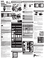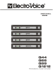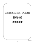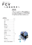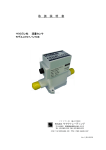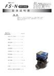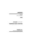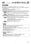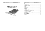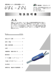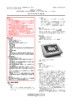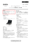
1
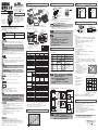
シール用Oリング
LCD
概 要
流量センサFS-Sは、マイクロプロセッサに
より、高い精度で流量検出します。
実流量値を常時外部にアナログ出力、同時に
LCDでデジタル表示。希望する設定流量に
対して、実流量が達しているかをLEDランプ
で表示、同時に警報出力(オープンコレクタ
出力)することができます。 【単体取付けブロック 寸法】 (単位:mm)
注意
誤った取扱いをしたときに、障害
または家屋・家財などの障害になる
恐れのあるもの。
40
絶対に行なわないで下さい。
FLOW SENSOR
POWER DOWN
FS-S
警告
CHECK
REGAL JOINT
STBY
OFF
異常・故障の発生
ON
UN-STAB
ON
STAB
煙が出ている、変なにおいがする、動作が不安定など異常・故障状態のまま使用すると火災、事故の原因となります。
このような時はすぐに電源供給をやめ、販売店に状況をご連絡下さい。お客様による分解修理は絶対におやめ下さい。
30
40
50
60
10
0
FS-3
10
20
30
70
*2
流量設定トリマー
【A 寸法値】(単位:mm)
A 幅
アダプタ
サイズ
BsBM
SUS
Rc3/8
92
98
Rc1/2
115
115
仕 様
屋内設置用に設計されていますので、屋外では使用しないで下さい。
型式
定格流量範囲
適用流体
検出方式
流体温度
周囲温度
*3
精度
最高使用圧力
電源電圧 *4
注意
ケーブルの取扱い
ケーブルに重いものを乗せたり、センサ本体からケーブルを引っぱったりすると事故・故障の原因となります。
使用していないケーブル同士、又はケーブルと外部機器が接触すると事故・故障の原因となりますので、1本ずつ絶縁処理
をしてからご使用下さい。
配線の際、出力の負荷条件、電源電圧の許容差が本書に記載された範囲外になっていると事故・故障の原因となります
ので、『配線方法』『出力信号』『仕様』の項目に記載された内容を必ずお守り下さい。
使用環境
電食の影響や静電気が帯電するような場所で使用すると、事故・故障の原因となります。
ケーブル
高周波電源周辺等電気的ノイズの影響を受けるような場所で使用すると、
事故・故障の原因となります。
流量表示
流体内に金属片、シールテープ等の異物が混入する恐れのある場合、必ず上流側にフィルタを設置して下さい。
流体中に気泡が混入していると正確に計測できません。気泡を十分除去してご使用願います。
*5
アラーム出力
開梱、持ち運び
開梱や持ち運びの際、落とさないように行なって下さい。センサ本体が落下し事故・故障の原因となります。
設置作業
アラーム表示
配管作業時など、センサ本体に指をはさむとケガの原因になりますのでご注意下さい。
その他
開梱時、中の製品に損傷や変形を発見した場合は、使用しないで販売店に状況をご連絡下さい。
保 守
保守点検
安全のため、水・電源の供給を止め、配管内を無加圧状態にしてから行なって下さい。
保管方法
● 弊社製品を保管される場合は、以下に記す条件を満たす場所で保管して下さい。
・雨、水のかからない場所。 ・直射日光の当たらない場所。・粉塵のない場所。
・振動、衝撃のない場所。 ・静電気対策がされている場所。
・周囲温度0~40℃の空調管理されている(結露、凍結しない事)場所。
※ 弊社出荷時の梱包状態のまま保管願います。
●弊社製品の誤った使用、不適切な使用により発生した事故に関しましては、弊社は責任を負いかねますのでご了承下さい。
・弊社製品についての保証期間は、製品納入から1年間となります。
・保証期間内での性能及び材質の不具合に対して、弊社責による原因であると弊社が文書で承認した場合、
代替品を提供させていただきます。
尚、此処での保証範囲は弊社製品単体に限定されます。製品の故障により直接あるいは間接的に起こる損失、
損傷、怪我、その他を含めた損害に関しては保証の対象範囲から除外します。
・要求により先行で代替品を提供、その後の不具合の原因調査により、弊社責でない事が判明した場合、代替品は
有償となります。
※代替品は基本的に同製品となりますが、弊社製造上の都合により同等品となる場合があります。
※弊社責外となる不具合要因例について以下に記します。
・取扱説明書(最新版)に記載している内容以外での使用。
・使用上の不注意。
・製品の分解、改造。
Max. 20mA(電圧出力時)
Max. 40mA(電流出力時)
DC40V未満
最大印加電圧
点灯
オープンコレクタ A・Bの2出力
アラーム設定値を A L/minとすると
緑色:1.2×Aより上
黄色:(1~1.2)×A
赤色:A未満
DC0~10V(負荷3kΩ以上)
DC4~20mA(負荷300Ω以下)
RoHS指令 (SUSアダプタ仕様のみ)
クロロプレンゴム or フッ素ゴム
φ5
φ7
●本書の内容の一部、又は全部を無断で転載、複製することは固くお断り致します。
●本書に記載された内容は、今後、特性改善などにより予告なく変更することがあります。
ご使用の際は、最新版をご参照下さい。最新版は当社ホームページ(URL http://www.rgl.co.jp/)で取得できます。
●本書に記載された動作概要、仕様などは、本製品の標準的な動作や特性を説明するためのものです。
従って、本製品の使用に当たっては、外部諸条件を考慮の上、最適な使用条件の元、適切な実装設計を行って下さい。
●本書の内容につきましては万全を期して作成しましたが、万一誤り、記載もれなどお気づきの点がありましたら
ご連絡下さい。
*性能改善のため、形状・仕様を予告なく変更することがありますのでご了承ください。
φ10
Rc3/8 or Rc1/2
約380g
}
10L/min
*3 F.S.(フルスケール)は なので、各々最大で の誤差があります。
±0.25L/min
±0.075L/min
*4 電源電圧は、注文時にDC12VまたはDC24Vのいずれかが選択できます。
*5 アラーム出力は、注文時に3S=2.0L/min、10S=6.0L/min、30S=20.0L/min設定となります。
*6 アナログ出力は、注文時に電圧出力、電流出力のいずれかが選択できます。
0.040
FS-30
0.035
(MPa)
0.025
FS-10
0.020
0.015
0.010
色
名称
特性
出力選択
DC12V±5%
DC24V±10%
赤 電源+
※7
2者択一
スクロール
②LCD表示
60
70
80
20
0
SET
②-2 流れ表示
塗りつぶしの部分が交互に表示し、
流れがあることを示します。
③トリマー
90
10
100
%
電源-側を接続。GND(0V)となる。
アナログ出力の-ラインとなる。
0~10V
4~20mA
2者択一
流量を電気信号に置換して装置側に送信する。
アナログ出力の+ラインとなる。
黄 アラーム出力(A) オープンコレクタ出力
アラーム信号を装置側へ通報。
( A ):流量≧アラーム値でON
茶 アラーム出力(B) オープンコレクタ出力
アラーム信号を装置側へ通報。
( B ):流量<アラーム値でON
アラーム出力の帰路となる。
GNDと独立。
緑 アラーム共通
接地ナシ(COM)
トリマー
③
●トリマー目盛 アラームを設定するときに使用します。(0~100%)で10%毎に目盛があります。流量(L/min)
とトリマーの数字(%)との概略の関係は、下図のグラフ及びセンサのケース側面に貼付
してあるラベルに表示してありますので、グラフを参考にして目盛を合わせ、アラーム動作
する流量を設定して下さい。
100
●アラーム設定方法
1.流量表示状態にて①チェックスイッチを押すと、
FS-3S
FS-3
LCD②-1 の数字が点滅します。
FS-10S
FS-10
2.LCD②-1が点滅している間に③トリマーをドライバ
50
(+または-)で回します。点滅している数字は
トリマーを回すことにより変化していきますので、
設定すべき流量に数字を合わせます。
(%)
3.設定後、再度①チェックスイッチを押下すること
0
10
により、流量表示状態に戻ります。
※7 出力選択に示されるものは、注文時にいずれか1つの仕様が選択できます。
※8 アラーム出力(A)=オフ出力、アラーム出力(B)=オン出力
警告 ・使用していないケーブル同士、又はケーブルと外部機器が接触
すると事故・故障の原因となりますので、1本ずつ端末を
絶縁処理してからご使用下さい。
・電源供給(1)仕様より過大な電圧を与えると破壊します。
(2)逆極性接続をすると破壊します。
・アナログ出力
出力線が電源にショートすると破壊します。
アラーム出力
④ LED表示
LED 赤色 STBY.(Stand by)
流量不足状態を示します。
LED 黄色 UN-STAB.(Unstable)
流量注意状態を示します。
LED 緑色 STAB.(Stable)
適量状態を示します。
VDD
FS-3S
FS-10S A未満
FS-30S
アナログ出力
VDD
FS-S
RL
D
FS-S
VDD
茶色ケーブル
アラーム出力
(B)
IL
0~10V
RL≧3kΩ
VDD
RL
(抵抗
負荷)
D
(リレー負荷)
VDD<40V、IL<100mAにて使用 (例:VDD=24V、RL=5.1kΩ)
アナログ出力
0.005
10 12 14 16 18 20 22 24 26 28 30
(L/min)
30
流量(L/min)
赤点灯
OFF
赤点灯
ON
ケーブル
⑤
6芯のキャブタイヤケーブルで、センサ本体への直流電源供給として2芯、センサ出力用として
4芯が束線されています。電源とアナログ出力は共通アース線を使用しています。
RL
メンテナンス
電流出力
FS-S
20
弊社では、アラーム出力と表示LEDの定義を
<表1>に定めております。
アラーム出力はオープンコレクタでONが導通、
OFFが非導通です。
電圧出力
黄色ケーブル
アラーム出力(A)
FS-30
FS-30S
<表1>アラーム出力と表示LEDの定義
アラーム
A
B
計測値
FS-3S A×1.2より上 緑点灯
緑点灯
FS-10S
ON
OFF
FS-30S A×1.1より上
FS-3S
黄点灯
黄点灯
A×1~1.2倍
FS-10S
ON
OFF
FS-30S A×1~1.1倍
アナログ出力
RL
4~20mA
RL≦300Ω
注意 ・リレー負荷時、逆起電力によるトランジスタの破損防止のため
ダイオード内蔵リレー(D)をご使用下さい。
・アナログ出力は、注文時の選択(電圧または電流出力)のいずれか
に設定されていますのでご確認の上ご使用下さい。
【センサ本体の取り外し】
1.電源をOFF にして下さい。(本機には電源スイッチは設置されていませんので、
電源ケーブルを取り外して下さい)
2.3mmの六角ドライバ、或いは六角棒レンチでアダプタ用のM4ネジ(六角穴付ボルト
M4×8) 4本をゆるめます。
3.センサ本体を、2.項でゆるめたアダプタ側へ少しずらします。
4.アダプタとセンサ本体の間に隙間ができ、本体のブロックの上側、或いは手前側に
引き抜くことができます。その際、配管内の水が流出する恐れがありますのでご注意下さい。
また、両側のOリングを落とさぬように注意して下さい。
5.取り付けは、取り外しの逆の手順で行います。
注意 両側のOリングは忘れずに必ず取り付けて下さい。
*メンテナンス上の不明点等ございましたら弊社までお問い合わせください。
製品の解体、分解による故障が認められる場合は、責任を負いかねます。
製造元
FS-3
2 4 6 8
STAB
50
}
動作・使用法
電源+側を接続。
+12Vもしくは+24Vを供給する。
緑色ケーブル
アラーム出力(共通線)
【圧力損失図】
下図は、元圧0.29MPaにおける1次圧力と2次圧力の差圧を示します。
ON
40
30
●②-3 パワーダウン表示について
直流電源電圧の低下時、(DC24V仕様の場合18V以下、DC12V仕様の場合9V以下)
②-3 が点滅します。
DC24V仕様の場合:DC24V±10%
以内に合わせて下さい。
DC12V仕様の場合:DC12V±5%
【各ケーブル機能】
電子回路の防滴
流量特性
UN-STAB
}
中継端子、コネクタなどにハンダ付け、または圧着により接続してください。コネクタのとき、
芯線サイズ♯24~♯28を推奨します。
自由
}
STBY
ON
②
LCD表示
DC電源を投入すれば②-1に流量をデジタル表示すると同時に、②-2は左から右へスクロールし、
流体があることを示します。流量に関係なく一定速度でスクロールします。
(流体がない場合はスクロールしない)
●流量は、
FS-3S :0.0~3.0L/min ステップ 0.1 のように表示します。
FS-10S:0.0~10.0L/min
FS-30S:0.0~30.0L/min 「UP」表示:仕様流量範囲を超えています。
配線方法(インターフェイス)
両方向
±0.75L/min
②-3 パワーダウン表示
②-1 デジタル表示
【操作】
①
チェックスイッチ
流量の設定、流量の確認、いずれかを選択するスイッチです。一度押すとLCDの数字が点滅し、
③のトリマーを操作することによりアラームの設定ができます。再度押すと、流量表示に戻ります。
配管から水を追い出す際、エアーの使用は避けてください。
センサの故障につながります。
アラーム出力
SUS or BsBM (Niメッキ)
3 L/min
OFF
JOINT
【負荷の取り方】 装置側負荷抵抗(RL)の標準的な取り方を示します。
ポリアセタール・ポリアミド
30L/min
④LED表示
赤色
黄色
緑色
【LCD表示拡大図】
①チェックスイッチ
/min
REGAL
3色LED
点灯
30
20
10
(L/min)
⑤ケーブル
CHECK
FS-S
LCD
0.030
取扱説明書について
緑色:1.1×Aより上
黄色:(1~1.1)×A
赤色:A未満
電源供給×75%にて1点 点滅LCD
電流出力
0 3
SENSOR
POWER DOWN
水の汚れが目立つ場合は、配管にフィルタを装着して下さい。
※8
2
AWM20276 (6芯 0.2mm 500mm)
0.1ステップ2桁LCD
0.1ステップ3桁LCD
3点定速スクロールLCD
DC100mA未満
緑色:1.2×Aより上
黄色:(1~1.2)×A
赤色:A未満
30
20
10
FLOW
警告
※8
DC12V±5% or DC24V±10%
出力モード
3
操作方法
Oリングを挿入しないで取付けた場合、水漏れを起こしますのでご注意下さい。
水、工業用水を扱う場合、
白 アナログ出力
1.0MPa
最大負荷電流
FS-30
4
【各部名称】
流量センサ本体と配管用アダプタ間のシール面には、Oリング P16が入っています。
黒 電源-
0~40℃ (凍結及び結露なきこと)
±2.5% F.S.
認証、規格など
接液部材質
接続部材質
シール用Oリング
オリフィス径
配管口径
質量
取付け姿勢
流れ方向
保護構造
表示カバーの内部には電子基板があり、触ると事故・故障の原因となります。
内部の点検・調整・修理は販売店にてご依頼下さい。
配管、配線作業、及び保守、点検は専門知識と経験を持った担当者が行なって下さい。
保証及び免責事項
羽根車式
数値
表示方式
FS-30S
5.0~30.0L /min
0~60℃ (凍結及び結露なきこと)
パワーダウン表示
アナログ出力 *6 電圧出力
(電圧,電流はご注文時選択)
FS-10S
1.5~10.0L /min
工業用水・水
消費電流
FS-10
トリマー回転
磁気や電磁波、放射線、紫外線のあたる場所で使用すると事故・故障の
原因となります。
FS-3S
0.5~3.0L /min
FS-3
12
(mA)
8
FS-30
(L/min)
流体感知部のゴミ溜りの原因となり、センサの故障につながります。
(ご相談に応じてフィルタもご用意致します)
40
*1) A寸法値はアダプタ種類によって異なります。
アダプタの口径は、注文時の選定により
決定します。
*2 操作方法を参照して下さい。
熱器具などの高温となる場所で使用すると内部の温度が上昇し事故・故障の原因となりますので、使用条件の下でご使用下さい。
0
破損する恐れがあります。(図2参照)
FS-30
0
100
%
FS-10
FS-10
50
%
90
SET
20
16
FS-3
2
六角レンチ(3mm)
3. 配管用アダプタの内径は、Rc3/8ネジ or Rc1/2ネジになっています。
4. 配管用アダプタは、六角穴付ボルトM4×8 4本で取付ブロックに固定されています。
取付け取外しには、3mmの六角ドライバかL型レンチを使用します。
注意
80
20
68
使用環境
本製品は防爆構造ではありませんので、可燃性ガス、爆発性ガス、腐食性ガス雰囲気等の危険な場所では使用しないで下さい。
配管
【 】電流出力(4~20mA)
Ⅱ
取付け忘れや噛み込み及びゴミなどが入らぬよう充分ご注意願います。
100
必ず指示に従い、行なって下さい。
湿気や結露の多い場所で使用すると水分が内部にたまり事故・故障の
原因となります。
震動、衝撃、脈動を受ける場所で使用すると、不正動作・事故・故障の
原因となります。
背面取付用
2×M4用 皿穴(皿小ネジ)
68.5
誤った取扱いをしたときに、死亡や重傷等の
重大な結果になる恐れのあるもの。
4
警告
底面取付用
4×M4用 ザグリ穴
(六角穴付ボルト)
8
6
(V)
4
注意 取付ブロックに直接スパナをかけますと、
単体取付けブロックは、取付け寸法により底面を固定(2個のM4 皿小ネジ使用)
背面を固定(2個のM4 六角穴付ボルト使用)或いは、パイプによる固定などが可能です。 A *1
10
1. 配管は配管用アダプタにねじ込むか、弊社製品のカンタッチ継手等を使用して行ないます。
2. 配管材の取り付けの注意
スパナ(35mm)をかける時は、必ず配管用アダプタの外周を使用して下さい。
4×M4
アダプタ用
(六角穴付ボルト) 反対側にも使用
この取扱説明書で使用している表示と意味は次の通りです。
M4×8 六角穴付ボルト
Rc3/8ネジ or Rc1/2ネジ
仕様シール
FS- 30…30L/min
FS- 10…10L/min
FS- 3… 3L/min
4
安全上のご注意
【 】電圧出力(0~10V)
Ⅰ
【図2】
配管アダプタ
30
●本製品を使用する前に、必ず取扱説明書を読んで内容を理解して下さい。
●取扱説明書で指定した使用方法、使用条件、注意事項を必ず守って下さい。
スパナ
OリングP16
単体取付ブロック
4
ご使用前に
流量センサ本体
4×M4用 ザグリ穴
(六角穴付ボルト)
底面取付用
配管用アダプタ
Rc3/8 or 1/2(両側)
LED
【図1】
スパナ(35mm)
2×M4用 皿穴
(皿小ネジ)
背面取付用
単体取付けブロック
19
●本書の最新版は
当社ホームページ
(http://www.rgl.co.jp/)
で取得できます。
AWM20276 6芯/0.2mm2
ケーブル 長さ500mm、端末未処理
センサ本体
出力信号
配管について
流体の流れに応じて回転する羽根車に磁石が搭載されており、その磁気を感知します。
磁気の変化により流量が算出され、流量表示すると同時に各種信号を出力することができます。
55.5
FS-3S/10S/30S
〒252-0331
神奈川県相模原市南区大野台1-9-49
TEL 042-756-7411(営業ダイヤルイン)
FAX 0120-85-7411( フリーダイヤル)
URL http://www.rgl.co.jp
構 成・寸法図
4
FS-S
株式会社 リガルジョイント
30
羽根車式
流量センサ
株式会社リガルジョイント
〒252-0331 神奈川県相模原市南区大野台1-9-49
TEL 042-756-7411(営業ダイヤルイン)
FAX 0120-85-7411 ( フリーダイヤル)
URL http://www.rgl.co.jp
第15版 2014年9月
● Please read carefully the instructions before you use our product.
● Please follow the procedures, conditions and cautions as per the instructions.
Safety information
100
FLOW SENSOR
If you continue using our product under the unusual or faulty connections or conditions like
as smoking, foul smell, unstable and malfunction, it could cause fire or accident. Cut the
power supply immediately and contact to us. Do not try to repair the product yourself.
Working environments
In the humid or dewing environment, it could cause accident
or damage because of moisture.
In the vibration, impulsion or pulsation environment, it could cause
malfunction, some accident or damage.
Our products are NOT explosion-proof. Do not use in the dangerous environment with
flammable, explosive, or corrosive gas.
Do not use outside. This product is only for inside.
Installation in high temperature environment as near to heat instruments could cause some
accident or damage as the heat instrument will led the temp rise inside the flow meter. Please
use our product as instructed in the manual.
Caution
Cables
Please do not put heavy objects on the cables or pull the cables from flow meter body, it could
cause accident or damage.
External device and cable or cable to each other, do not use come into contact with, you cause
an accident or malfunction. Please use it after the insulation process one by one.
Please follow the Instructions for "wiring", "Output signal ", "how to put a load output ",
"Specifications "other wise, it could cause accident or damages.
Working environments
Magnetic power, electromagnetic wave, radioactive ray or
ultraviolet rays could cause accident or damage.
Electric corrosion or static electricity could cause accident or damages.
In electrically noisy environments as like around high-frequency
power source could cause accident or damages.
Install the filter upper flow/Inlet to clear some piece of metal or small objects if needed.
Remove the bubbles in the fluid for accurate measurement of flow rate.
STBY
40
ON
UN-STAB
ON
STAB
50
80
90
0
SET
%
40
Trimmer *2
2×M4 screw hole
(countersink head bolt)for rear mounting
*1 Dimention A differ depending upon the adapter type.
【 A Dimension Table】
Adapter connection size is determined by the selection
A dimension
Adapter
at the time of the order.
connection size
BsBM
SUS
Rc3/8
92
98
*2 Please refer to the Operating method.
Rc1/2
115
115
Specifications
Model
Rated flow range
Applicable fluid
Detection type
Fluid temperature
Operating temperature
Accuracy *3
Max.working pressure
Power supply voltage *4
FS-3S
FS-10S
0.5 ~ 3.0L /min
1.5 ~ 10.0L /min
Industrial water, Water
Impeller type
Maintenance
Contact us for overhauling, adjusting or repairing. Please make sure not to touch an electronic
substrate inside of flow meter.
Only a person who has technical knowledge and experiences could do plumbing, wiring,
maintenance or overhauling.
While installation or maintenance please shut off the power and water supply for your safety.
Storage
●Please store our products under environments as follows.
・Where it is NOT exposed to rain or water.
・Where it is NOT exposed to direct sunshine.
・Where it is NOT exposed to dust.
・Where it is NO vibration or impact.
・Where it is static-free.
・Where ambient environment is controlled between 0-40 degree Celsius without
dewing and freezing.
・Please store our products as you received.
Warranty and disclaimer
●We are not responsible regarding the accident that occurred from the incorrect
use of our products or possible lack of information in this document.
・Warranty period of our product is one year from the received date of the product(s).
・If the claimed defect of specifications or materials in the period of the warranty are verified with
a document, we will replace free of the product(s). This warranty covers only our products. This
warranty does not cover direct or/and indirect damages like lost, damages or injurers etc. caused
by defected products.
・We supply a replacement on request. And an inspection of the equipment does not disclose any
defect causing by us, the replacement will be charged.
*The replacement is the same product as we sold but we would supply a different product for
certain reasons.
*It refers the case which we do not have any responsibility.
In use out of non-compliance regarding this instruction manual.
Negligence in use.
Dissembling or conversion of our products.
About instructions manual
●It is not allowed to reprint or reproduce a part or full instruction manual without any prior
permission by us.
●All the contents of instruction manual are correct at the date of publication and are subjected to
change without notice. Please save the latest issue of our products.Please get our website at
(URL http://www.rgl.co.jp/) the latest version.
●The contents of the outline and specification of the flow sensor in this operating manual has
followed as per the standards. Care must be carried out properly while using sensor with a
proper lay-out and consideration against external condition.
●Please contact us if you acknowledge any mistakes or unlisted information in this instruction manual.
*The design, dimensions and specifications of the product in the catalog were correct at the date
of publication and are subjected to change without notice.
FS-30S
5.0 ~ 30.0L /min
0 ~ 60℃ (No freezing , no dewing)
0 ~ 40℃ (No freezing , no dewing)
±2.5% F.S.
1.0MPa
DC12V±5% or DC24V±10%
Max. 20mA
Max. 40mA
2
AWM20276 (6cores 0.2mm 500mm)
2 digits LCD
3
digits
LCD
with every 0.1 Pitch
with every 0.1 Pitch
Flow Rate Display
Constant scrolling LCD at 3 points
Max. load current Less than DC100mA
*5
Alarm output
Max. applied voltage Less than DC40V
Output mode
A or B open collector output
If alarm set value is regarded as A L/min.,
・Green lighting:
1.2×A or more
・Yellow lighting:
(1 - 1.2)×A
・Red lighting:
A or less
Lighting
・Green lighting:
1.2×A or more
・Yellow lighting:
(1 - 1.2)×A
・Red lighting:
A or less
・Green lighting:
1.1×A or more
・Yellow lighting:
(1 - 1.1)×A
・Red lighting:
A or less
Power Down Display
1blinking point LCD on power supply at 75% of the power supply.
Analog output *6 Voltage output
(When ordering,voltage
or current output
Current output
can be selected)
DC0 ~ 10V
Display
Numeric value
Lighting
Standard
Wetted material
Connection material
O-ring for sealing
Orifice diameter
Adapter connection size
Weight
Mounting position
Flow direction
Construction
Piping adapter
1. Piping connection must be done by means of screw into the piping adapter or by using
KANTOUCH coupling made by REGAL JOINT CO., LTD.
2. Caution while fitting piping material
When applying a spanner (35mm)to fit the piping material, never fail to put it on the outer
circumference of the piping adapter.
Caution
FLOW SENSOR
O-Ring (Type P-16) is inserted to the sealing surface between the Flow sensor
body and Piping adaptor.
Do not forget to insert it and take care of twisting and strucking dust to it as it could affect
the result in accuracy.
}
Warning
Fitting the sensor body without O-rings might cause leakage.
Please install the water filter in the pipe in case of handling impure water.
Do not use air while driving out the water from water pipes. It could lead the failure of
flow sensor.
Wiring (Interface)
Connect the cable with the junction terminal and connector by means of soldering or crimping tool.
It is recommended to use a cable with #24~#28 of the core size for connector.
【Cable functions】
Characteristic
Name
Red
Power Supply(+)
Black
Power Supply(-)
White
Analog output
*8
Yellow Alarm output(A)
*8
Brown Alarm output(B)
Green Alarm output
cable commonly
used
DC12V±5%
DC24V±10%
Output *7
selection
Operation and usage
4~20mA
A output
open collector
+side of power supply.
Alternatively Connect
Supply +12V or +24V.
Connect -side of power supply.
It is GND(0V) .
It is -line of Analog output.
The flow rate is converted into an
Alternatively electric signal, which is sent to the
equipment side.It is +line of analog output.
Alarm is reported to the equipment side.
( A ):Flow rate ≧alarm value :ON
B output
open collector
Alarm is reported to the equipment side.
( B ):Flow rate < alarm value :ON
Do not ground
(COM)
Return of alarm output.
Independent of the GND.
0~10V
*7 Analog display is transmitted of either voltage or current output at the time of the order.
*8 Alarm output(A)=OFF output,Alarm output(B)=ON output.
Warning
(1)Because it becomes the cause of accidents and failure external equipment
and cables are in contact with each other or cable, do not use, please use it
after the insulation process one by one.
(2)Voltage more than specified on the table will damage the product.
(3)Anti-polar connection might result destruction of the flow sensor.
(4)Analog output
Alarm output It will destroy the output line is a short circuit in the power supply.
DC4 ~ 20mA ( under 300Ωload)
φ7
Alarm output
FS-S
φ10
Flow Rate Characteristics
Following diagram shows pressure
difference between primary and secondary
pressure at 0.29MPa of original pressure.
FS-10
2 4 6 8 10 12 14 16 18 20 22 24 26 28 30
(L/min)
L/min
REGAL JOINT
Voltage Output
D
FS-S
Analog Output
RL
Brown cable
alarm output
(B)
IL
0~10V
RL≧3kΩ
VDD
RL
(Resistance
load)
D
Analog Output
Relay load
Green cable
alarm output
(common cable)
Use at : VDD<40V,IL<100mA(Example:VDD=24V、RL=5.1kΩ)
10
(L/min)
20
30
④LED
Red
Yellow
Green
40 50 60
70
30
80
20
90
10
0 SET 100
%
OFF
ON
ON
[LCD Display]
②-3 Power down display
②-1 Digital display
Scrolling
③Trimmer
②-2 Flow display
[Operation]
① Check Switch
This switch is used either for setting or checking the Flow rate. Pushing it once, the digital
display of LCD start blinking and the alarm can be set by using ③ trimmer. Pushing it again,
flow rate comes back on the display.
② LCD Display
After inputting DC power supply the flow rate is displayed digitally on ②-1 and at the same
time ②-2 starts scrolling from left to right showing the existance of flow rate. It doesn't
related on the flow rate and continues scrolling constantly. (If there is no flow then no scroll
will be appeared.) Flow rate is displayed as follow and when overflow occurs, indication of UP will be displayed.
[UP]:Flow rate exceeds the specification flow range. FS-3S :0.0~ 3.0 L/min
FS-10S:0.0~10.0 L/min
with a pitch of 0.1 L/min
FS-30S:0.0~30.0 L/min ②-3 Power Down Display
When DC power voltage gets lower(under 18V for DC 24V specification and under 9V for
DC12V specification ),②-3 will start blinking. DC power voltage should be within following range.
In case of 24V specification : DC24V± within 10%
In case of 12V specification : DC12V± within 5%
③ Trimmer
● Trimmer scale
Trimmer scale is used for setting alarm with 0~100% scales with every 10%
adjustment. Approximate relation between Flow rate (L/min.)and ③Trimmer figures (%)
are shown in following graph as well as the label pasted at the side of the sensor case.
Refer both the graphs and set up the desired flow rate as per the requirement.
● Alarm Setting Method
After inputting DC power supply, the flow rate is displayed digitally on ②-1
and at the same time ②-2 starts scrolling from left to right showing the existance of flow
rate. It doesn't related on the flow rate and continues scrolling constantly. (If there is no
flow then no scroll will be appeared.)
}
(
④ LED Display
100
LED STBY.(=Stand by)
Shows an insufficient flow rate condition.
Yellow UN-STAB.(=unstability)
Shows an critical condition of flow rate.
Green STAB.(=Stability)
Shows moderate flow rate condition.
The definitions of the alarm output
and display LED are specified in
<Table 1>by Regal Joint.
For the alarm output , ON indicates
conductive and OFF indicates
non-conductive in open-collector.
<Table 1>
FS-3S
FS-3
50
0
FS-10S
FS-10
FS-30
FS-30S
10
20
30
Flow rate(L/min)
Alarm
Measurement value
FS-3S above 1.2 times of A
FS-10S
FS-30S above 1.1 times of A
FS-3S
FS-10S 1~1.2 times of A
FS-30S 1~1.1 times of A
FS-3S
FS-10S less than A
FS-30S
A
Green lamp
is ON
ON
Yellow lamp
is ON
ON
Red lamp
is ON
OFF
B
Green lamp
is ON
OFF
Yellow lamp
is ON
OFF
Red lamp
is ON
ON
⑤ Cable
This is a 6 cores cab tire cable consisting of 2 cores for DC power supply to the flow
sensor itself and 4 cores for sensor output, while a common earth wire is used for power
source and analog output.
Maintenance
[Removing Sensor Body]
Current Output
FS-S
3
①Check Switch
②LCD Display
Analog output
VDD
RL
VDD
}
*4 Power supply is transmitted of either DC 12V or DC 24V at the time of the order.
*5 Alarm output is set at the time of the order , 3S = 2.0L/min, 10S = 6.0L/min, and 30S = 20.0L/min.
*6 Analog output is transmitted of either voltage or current output at the time of the order.
VDD
Yellow cable
alarm output
(A)
Rc3/8 or Rc1/2
Approx. 380g
Free
Both direction
Water drip-proof against electronic circuit
30L/min
±0.75L/min.
10L/min , the deflection could be of
±0.25L/min.
3 L/min
±0.075L/min.
FS-30
FS-S
⑤Cable
CHECK
【How to bear load resistance】
Following diagram shows how the apparatus bear the load resistance generally.
LCD
LED
RoHS compliance (Only SUS adapter)
Polyacetal,Polyamide
SUS or BsBM (Ni plating)
Chloroprene or Fluoro rubber
0
30
20
Operating method
Putting the spanner directly on the fitting block might cause a breakage
of the flow sensor(see Fig.2).
Caution
(1)
(2)
(3)
4
(L/min)
FS-30
(mA) 12
8
10
FS-10
16
FS-30
2
3
FS-3
20
4
0
Allen Key(3mm)
O-Ring P16
Fitting block
[Current output](4~20mA)
(V) 6
(over 3kΩload)
φ5
*3 Since F.S.(Full scale) is
[Pressure Loss Diagram]
0.040
0.035
0.030
0.025
(MPa)
0.020
0.015
FS-3
0.010
0.005
Spanner (35mm)
Rc3/8 Rc1/2 screw
Piping
Color
Voltage output
Current consumption
Current output
Cable
Alarm display
[Fig.2]
Spanner
M4×8
hexagonal head cap bolt
100
Others
Please contact us if you received damaged or deformed product.
30
70
10
Do not drop ,Handle with care otherwise The flow meter could damage or cause
malfunctioning.
Mind your fingers while plumbing a sensor or you could get injured.
20
60
30
20
68
Packaging and carrying.
Installations
10
4
REGAL JOINT
OFF
FS-30
0
FS-S
Warning
Unusual or faulty conditions
50
%
CHECK
POWER DOWN
FS-10
30
Do it only with
following instructions.
FS-3
4
Caution
40
Never do it.
Sensor body
3. Inner diameter of the piping adapter is Rc 3/8” or Rc1/2”.
4. The piping adapter is fixed on the fitting block by using 4 Nos. of the hexagonal head cap
bolt M4×8. Use a 3mm hexagonal screw driver or L-Type wrench for mounting and detaching
the dapter.
A *1
19
Warning
Mishandling could cause injury
or even death at drastic
conditions.
Mishandling could cause disability, fire or
other damages to the building or
properties.
【Block size】
[Fig.1]
[Voltage output](0~10V)
FS-3
10
FS-10
8
Trimmer
Revolution (%)
Before using our product.
4×M4 screw
(hexagonal head cap
bolt)for adapter
Fitting block can be fastened by means of either bottom fitting (by using 4 Nos. of M4
of hexagonal head cap bolt). For rear fitting(by using 2Nos. of M4 of a small
countersinking screw)or by means of pipe construction depending on fitting way. 68.5
This flow sensor Type FS-S is used for
measuring flow rate at high accuracy.
Microprocessor processing technique make it
possible to sense the measuring value very
precisely. The result of measuring outputs to
external terminal as analogue value and is
shown as digital value on LCD.
Further the result of displayed data compares
the reference value to detect alarm signal,
which output to "Open Collector" terminal and
turns the LED on. 55.5
FS-3S/10S/30S
Out line
The flow rate depends corresponding to the rotating impeller equipped with magnets which is percieved
by the magnetic sensor. Flow rate is calculated and displayed by changing magnetism, at the same time
output signals are output as a result.
2×M4 screw hole
Cable
(Countersink head bolt
Sensor body
Fitting block
for rear mounting)
4×M4 bolt hole
O-ring
(hexagonal head
Piping adapter
LCD
cap bolt)for bottom
LED Rc3/8 or 1/2screw
mounting
on both sides
Specifications
seal
FS- 30…30L/min
FS- 10…10L/min
FS- 3… 3L/min
4
Instructions Manual
1-9-49 Onodai Minami-ku
Sagamihara-shi Kanagawa Japan
252 0331
URL http://www.rgl.co.jp
Output signals
Connections
Configuration and Dimensions
30
FS-S
Tel +81-42 756 7411
Fax +81-42 752 2004
4
Impeller
flow meter
RL
4~20mA
RL≦300Ω
Caution
・When operating the unit under a relay load, use a diode built-in relay (D) to prevent breakdown of the transistor due to a counter-electromotive force.
・Analog display is transmitted on delivery of either voltage or current output.
(1) Turn the power supply OFF(Power supply cable must be taken out, becauce this flow sensor
is not provided with power supply switch).
(2) Loosen 4 Nos. of M4 screws for the adapter(hexagonal socket head cap bolt M4×8) by using
a Allen key.(see following figure)
(3) Slide the Flow sensor body slightly towards the loosened adapter as directed above. (2)
(4) Some space appears between the adapter and flow sensor body. Sliding the sensor body
towards flowing direction, the sensor body can be pulled out towards the upward direction
of the block or towards the side. At that time, care must be taken that fluid inside piping
might run over.
(5) Installation can be done in reverse side of the flow sensor.
Caution
Be careful that O-rings on both sides do not fall down.
*Please contact us if you have any questions or concerns of maintenance on.
If the failure dismantling of the product, due to the decomposition is found, I will not be responsible.
Manufacturer
Tel +81-42 756 7411
Fax +81-42 752 2004
1-9-49 Onodai Minami-ku
Sagamihara-shi Kanagawa Japan
252 0331
URL http://www.rgl.co.jp
<15th edition 201409>