1
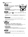
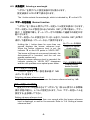
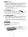
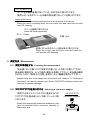
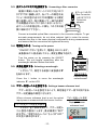
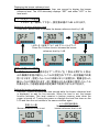
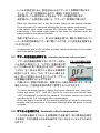
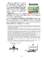
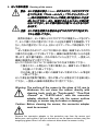
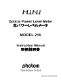
Optical Power Level Meter
光パワーレベルメータ
MODEL 216
Instruction Manual
取扱説明書
HR1336-13J-02/110404
目次
【 取扱上の
取扱上の注意 】 ........................................................................................1
1. 特長 ............................................................................................................3
2. 構成 ............................................................................................................4
3. 各部の
各部の名称と
名称と説明 .......................................................................................5
3-1. 各部の
各部の名称 .........................................................................................5
3-2. 表示部 ................................................................................................6
3-3. 受光部 ................................................................................................6
4. 操作 ............................................................................................................7
4-1. 電池 ....................................................................................................7
4-2. 電源操作 ............................................................................................7
4-3. 波長選択 ............................................................................................8
4-4. ブザー判定機能
ブザー判定機能 ..................................................................................8
4-5. 初期リセット
初期リセット ........................................................................................9
4-6. ストラップの
ストラップの取り付け ...........................................................................9
4-7. カバーの
カバーの取り外しと取
しと取り付け ................................................................9
5. 測定方法 ...................................................................................................10
5-1. 測定の
測定の準備をする
準備をする .............................................................................10
5-2. コネクタアダプタを
コネクタアダプタを取り付ける ............................................................10
5-3. 光ファイバコネクタを
ファイバコネクタを接続する
接続する ...........................................................11
5-4. 電源を
電源を入れる ....................................................................................11
5-5. 波長を
波長を選択する
選択する ................................................................................11
5-6. ブザー判定
ブザー判定レベル
判定レベルを
レベルを設定する
設定する ...........................................................11
5-7. ブザー判定機能
ブザー判定機能を
判定機能を解除する
解除する ..............................................................13
5-8. オフセットを
オフセットを補正する
補正する .........................................................................13
6. センサ部
センサ部の清掃 ........................................................................................15
7. 規格 ...........................................................................................................16
7-1. 光パワーメータ仕様
パワーメータ仕様 ..........................................................................16
7-2. 一般仕様 ...........................................................................................16
8. オプション ..................................................................................................18
9. アフターサービス .......................................................................................18
Index
【 CAUTION 】 ..................................................................................... 2
1. Characteristics ................................................................................. 3
2. Configuration .................................................................................... 4
3. Descriptions of the user interface ................................................... 5
3-1. User interface ............................................................................ 5
3-2. LCD display ............................................................................... 6
3-3. Sensor port ............................................................................... 6
4. Operation instructions ..................................................................... 7
4-1. Battery ....................................................................................... 7
4-2. Power ......................................................................................... 7
4-3. Selecting a wavelength ............................................................ 8
4-4. Buzzer function ......................................................................... 8
4-5. Initializing .................................................................................. 9
4-6. Strap hole .................................................................................. 9
4-7. Cover ......................................................................................... 9
5. Measurement .................................................................................. 10
5-1. Preparing the measurement .................................................. 10
5-2. Attaching a connector adapter .............................................. 10
5-3. Connecting a fiber connector ................................................ 11
5-4. Turning on the power ............................................................. 11
5-5. Selecting a wavelength .......................................................... 11
5-6. Setting a buzzer reference level ............................................ 11
5-7. Canceling the buzzer reference level .................................... 13
5-8. Automatic offset compensation ............................................ 13
6. Cleaning of the sensor ................................................................... 15
7. Specifications ................................................................................. 16
7-1. Sensor specifications ............................................................. 16
7-2. General specifications ........................................................... 16
8. Option ............................................................................................. 18
9. After-sales service information ..................................................... 18
【 取扱上の
取扱上の注意 】
(1)
). 光 センサ受光部
センサ 受光部は
受光部 は ホコリ等
ホコリ等によって性能
によって性能が
性能が著しく悪化
しく悪化しますので
悪化しますので、
しますので、コネク
タやアダプタ等
アダプタ等の脱着時に
脱着時にホコリが
ホコリが入らない様
らない様に充分に
充分に注意して
注意して下
して下さい。
さい。
使用しない
使用しない時
しない時は必ずカバーを
カバーを取り付けて下
けて下さい。
さい。
(2)
). 使用前に
使用前に「6. センサ部
センサ部の清掃」
清掃」にしたがってセンサ
にしたがってセンサ部
センサ部を清掃して
清掃して下
して下さい。
さい。
(3)
). 光ファイバコネクタ以外
ファイバコネクタ以外のものを
以外のものをコネクタアダプタ
のものをコネクタアダプタに
コネクタアダプタに挿入しないで
挿入しないで下
しないで下さい。
さい。
(4)
). 光ファイバコネクタは
ファイバコネクタは規格に
規格に準拠したものを
準拠したものを使用
したものを使用して
使用して下
して下さい。
さい。
規格に
規格に準拠しない
準拠しない光
しない光ファイバコネクタや
ファイバコネクタや裸心線ファイバアダプタ
裸心線ファイバアダプタを
ファイバアダプタを使用す
る 場合は
場合 は 、測定器に
測定器 に 光 ファイバパッチコードを
ファイバパッチコードを接続して
接続して測定
して測定するか
測定するか、
するか、コネ
クタアダプタに
クタアダプタに 光 コネクタを
コネクタを 接続したときに
接続したときにコネクタアダプタ
したときにコネクタアダプタから
コネクタアダプタから突
から突き出す
フェルールの
フェルールの長さが 0.5mm 以下になるようにして
以下になるようにして下
になるようにして下さい。
さい。規格に
規格に準拠し
準拠し
た光ファイバコネクタを
ファイバコネクタを接続した
接続した場合
した場合は
場合は 0.5mm 以下になります
以下になります。
になります。
光ファイバコネクタ
光ファイバフェルール
コネクタアダプタ
▼
▲
コネクタアダプタから突き出す光ファイバフェルール
の長さが 0.5mm 以下になること
コネクタアダプタに光コネクタを接続したときの図
(5)
). 裸心線ファイバアダプタ
裸心線ファイバアダプタを
ファイバアダプタを使用する
使用する場合
する場合は
場合は、フェルール端面
フェルール端面より
端面より石英
より石英ファ
石英ファ
イバが
イバが突き出さないようにして下
さないようにして下さい。
さい。
(6)
). 過大な
過大 な 光入力は
光入力 は 光 センサを
センサ を破損しますので
破損しますので、
しますので、測定範囲上限を
測定範囲上限を著しく越
しく越え
るような光
るような光を入光しないで
入光しないで下
しないで下さい。
さい。
(7)
). 外部からの
外部からの過大
からの過大な
過大なノイズ等
ノイズ等で正常に
正常に動作しなくなる
動作しなくなる事
しなくなる事があります。
があります。その場
その場
合 は 電源を
電源 を 入 れ 直 して下
して 下 さい。
さい 。それでも回復
それでも 回復しない
回復 しない場合
しない 場合は
場合 は 、一旦、
一旦 、電池
を 抜 いてから再
いてから 再 び 電池を
電池 を 入 れ 、“ λ ボタン”
ボタン ” を 押 しながら電源
しながら 電源を
電源 を 入 れ 直 し
て下さい。
さい。
(8)
). 落したり、
したり、振り回したりしないで下
したりしないで下さい。
さい。
-1-
【 CAUTION 】
(1). The surface of the sensor built in the input port should be
kept away from dust or other impurities, in particular, be
careful removing and fitting connectors or adapters.
(2). Before use, clean the Sensor-port with canned air or a new
cotton swab according to "6. Cleaning of the sensor".
(3). Do not insert anything other than the optical fiber connector
into the connector adapter.
(4). Use a standard optical fiber connector. When using a
nonstandard optical fiber connector or a bare fiber adapter,
connect a optical patch code to the connector adapter or limit
the protruding length of the optical fiber ferrule to 0.5 mm.
When using a standard optical fiber connector, the length is
less than 0.5 mm. The protruding length is defined as below.
Optical fiber connector
Optical fiber ferrule
Connector adapter
▼
▲
Protruding length is the length of the optical
fiber ferrule protruding out of the connector
adapter.
Figure showing the connection of an optical fiber connector to a connector adapter
(5). When using a bare fiber adapter, insert the fiber such that it
does not protrude out of the ferrule end-face.
(6). Do not input optical power greatly beyond the max. measuring
range, or the photo diode will be damaged.
(7). Excessive ambient noise may affect the normal operation. In
that case, first turn the unit off and then turn it on.
Nevertheless in case of not removing, take the battery off and
put in again, then turn the power “ON” pushing and holding
down the “λ
λ” button together.
(8). Do not drop or swing the instrument with the strap.
-2-
1. 特長 Characteristics
(1). 光ファイバを使用した光通信等の光パワー量、光減衰特性などを測定
する、軽量ポケット型の「ミニ」光パワーメータです。
This lightweight pocket-type MiNi optical power level meter is designed to
measure optical power and attenuation in fiber optics communication.
(2). 測定波長は、1310nm, 1490nm, 1550nm で校正されています。
It is calibrated at three different wavelengths (1310 nm, 1490 nm, 1550 nm).
(3). 光パワーメータにブザー判定機能が付いているため、ブザー判定レベル
より大きな光パワーレベルを受けるとブザー音で知らせてくれます。ブザ
ー判定レベルが設定されるとオートパワーオフが解除するため、連続での
測定が可能になります。
The optical power meter has a buzzer function that beeps when the optical
input power exceeds a predetermined reference level. The meter operates
continuously when the buzzer reference level is set and the Auto-power-off is
canceled.
(4). VOX 機能の付いたトランシーバーを使うと、離れた場所でも光パワーメ
ータの測定結果を確認することができます。
Possible to check optical input power at remote location by using transceiver
with VOX function together.
(5). 先端のアダプタの交換で、規格に準拠した各種の光コネクタと接続が可
能です。
It can be connected to various kinds of connectors by using the appropriate
connector adapters.
(6). メモリ機能により、電源を切っても設定波長とレベル設定を記憶します。
A memory backup function stores selected a wavelength and a buzzer
reference level even when the unit is turned off.
(7). ブザー判定レベルが設定されていなければ、オートパワーオフが機能し
て電源切り忘れを防止します。
If the buzzer reference level is not set, the Auto-power-off is set to prevent the
operator from forgetting to turn off the power.
(8). 使用時以外は、カバーにより、受光部及び表示操作部が保護されます
から、そのままポケットや工具箱に収納できます。
Small and well-designed cover protects input port and operation buttons,
suitable for carrying in a pocket or toolbox.
-3-
2. 構成 Configuration
本体と、本体に内蔵されたセンサ部、そして各種の光ファイバコネクタに対
応するためのコネクタアダプタ部(別売)により構成されます。
This optical power level meter consists of the main body and the built in sensor,
and connector adapters accommodating various fiber connectors.
FC
FC
SC
SC
ST
ST
本体
Main unit
センサ部
Sensor
光ファイバコネクタ
コネクタアダプタ
Fiber connectors
Connector adapters
注意 CAUTION
旧型コネクタアダプタ
旧型コネクタアダプタ 180-ST は使用しないで
使用しないで下
しないで下さい。
さい。センサが
センサが破損する
破損する可
する可
能性があります
能性があります。
があります。新型コネクタアダプタ
新型コネクタアダプタ 180-ST を使用して
使用して下
して下さい。
さい。
The old 180-ST adapter may damage the sensor. Please use the new 180-ST
adapter instead.
旧型(old) 180-ST
新型(new) 180-ST
光コネクタを
コネクタをコネクタアダプタ 180-UA に挿入するときは
挿入するときは、
するときは、センサを
センサを破損す
破損す
ることがあるので強
ることがあるので強い力で挿入しないで
挿入しないで下
しないで下さい。
さい。
Please be careful when inserting fiber connectors in the 180-UA adapter.
Forceful insertion may damage the sensor.
-4-
3. 各部の
各部の名称と
名称と説明 Descriptions of the user interface
3-1. 各部の
各部の名称 User interface
①ストラップ取付部 Strap hole
⑧カバー
Cover
②受光部 (センサ部) Sensor port
③レベル設定表示部
Level set indicator
④表示部 (LCD)
LCD display
⑤λ ボタン
λ button
⑥ON/OFF ボタン
ON/OFF button
⑦電池収納部
Battery compartment
① ストラップ取付部
Strap hole
② 受光部 (センサ部)
Sensor port
③ レベル設定表示部
Level set indicator
④ 表示部 (LCD)
LCD display
⑤ λ ボタン
λ button
ストラップ取り付け用の穴です
The strap hole provides a connection for a strap.
光パワーを入力する光学的接続部です
The sensor port accepts the optical power input.
ブザー判定レベルが設定されていると▼が表示します
The indicator ▼ points to “LEVEL SET” when a buzzer
reference level is set.
測定状態を表示します
The LCD display indicates measuring data and status.
波長選択とブザー判定レベル設定のボタンです
The λ button selects a wavelength and sets the buzzer
reference level.
⑥ ON/OFF ボタン
ON/OFF button
電源の入力と切るためのボタンです
The ON/OFF button turns on/off the power of the unit.
⑦ 電池収納部
Battery compartment
⑧ カバー
Cover
電池を収納します
The battery compartment is used to install a battery.
本器を衝撃から保護するためのものです
The cover protects the unit from damage.
-5-
3-2. 表示部 LCD display
” 表示部”の LCD に測定データを表示します。受光値の他に下図の
表示もします。
The LCD display indicates measuring data and status.
LCD
電池電圧低下表示 電池電圧が低下すると点灯
“B” indicates when the battery voltage is low.
オートパワーオフ 自動電源 OFF 機能
“Auto-OFF” indicates when Auto-power-off is
set.
波長表示 ▼で測定波長を表示
Wavelength is indicated with ▼.
レベル設定表示 ブザー判定レベルが設定されると▼が表示
The indicator ▼ points to “LEVEL SET” when a buzzer reference
level is set.
3-3. 受光部 Sensor port
” 受光部(センサ部)”には、各種光コネクタに適合したコネクタアダプ
タが取り付けできます。
受光部は汚れにより性能、精度が著しく低下します。使用の前に清掃
をして下さい。受光部の清掃は、「6. センサ部の清掃」を参照して下さ
い。
受光部を破損させないために「取扱上の注意」を読み、正しく機器を
使用して下さい。
The sensor port accepts input optical power from fiber optics; attaching
interchangeable adapters accommodates a variety of connector types. Dust
or dirt can degrade the performance and accuracy significantly; therefore,
the sensor should be cleaned before use. Refer to “6. Cleaning of the
sensor”.
Read “CAUTION” and then use the unit correctly to prevent damage.
-6-
4. 操作 Operation instructions
4-1. 電池 Battery
電池の装填
電池蓋を下方にスライドさせて、電池収納部
に単 3 電池 1 本を内部の極性マークに従って装
填し電池蓋を閉めます。
Installing AA battery
Slide the battery cover off as indicated. Insert or
replace one AA battery as indicated by the polarity
marks in the battery compartment.
本器裏面
Rear side
単三乾電池
AA Battery
電池蓋
Battery cover
電池の交換
使用中、LCD 表示部に B マークが点灯した場合は速やかに新しい電
池と交換して下さい。
長時間使用しないときは、電池液漏れを防ぐため電池を必ず抜いて
下さい。
Replacing AA battery
Replace AA battery to new one, if “B” mark is indicated on the LCD.
When storing the unit for long periods, remove the battery to prevent
damage due to battery leakage.
4-2. 電源操作 Power
電源を入れる
“ON/OFF ボタン”を押すと電源が入り測定ができます。
電源を入れるときに 3 秒以上このボタンを押し続けると、オートパワー
オフ機能が解除されて LCD の「Auto-OFF」表示が消えます。
Turning on the power
Pressing the ON/OFF button will turn on the unit.
Hold the button down for three seconds when turning the power on. The
message “Auto-OFF” will disappear from the LCD. The Auto-power-off is
disabled now.
電源を切る
電源が入った状態で“ON/OFF ボタン”を押すと電源が切れます。
Turning off the power
Pressing the ON/OFF button during the measurement will turn off the unit.
-7-
4-3. 波長選択 Selecting a wavelength
“λボタン”を押すごとに設定波長が切り換わります。
設定波長は LCD の▼で表示されます。
The λ button selects the wavelength, which is indicated by ▼ on the LCD.
4-4. ブザー判定機能
ブザー判定機能 Buzzer function
“λボタン”を 1 秒以上押すとブザー判定レベル設定の表示になります。
ブザー判定レベルが設定されると「LEVEL SET」に▼が表示し、ブザー
音が 1 秒間隔で鳴り、オートパワーオフが解除して連続での測定が可
能になります。
ブザー判定レベルが設定されていないときは、「LEVEL SET」の▼が
消灯して通常の光パワーメータとして使用できます。
Holding the λ button down for more than one
second displays the buzzer reference level.
When the buzzer reference level is set, the
indicator ▼ on the LCD points to “LEVEL SET.”
The buzzer will beep at one-second intervals, the
Auto-power-off is canceled, and the unit can
operate continuously.
When the buzzer reference level is canceled, the
indicator pointing to “LEVEL SET” disappears
and the unit operates as an optical power meter.
ブザー判定レベル選択
“λボタン”を押すごとに設定表示値が 1dB
上がっていきます。
光パワーメータの表示
Display for optical
power meter
ブザー判定機能の表示
Display during
buzzer function
Selecting a buzzer reference level
Press the λ button once to increase the buzzer reference level by 1 dB.
ブザー判定レベル設定
設定したいレベルを表示させて“λボタン”を 1 秒以上押すか 5 秒間無
操作状態が続くと、レベルが設定されます。「5-6. ブザー判定レベルを
設定する」を参照して下さい。
Setting a buzzer reference level
Hold the λ button for more than one second while the buzzer reference
level is displayed, or wait for five seconds. Refer to “5-6. Setting a buzzer
reference level.”
-8-
4-5. 初期リセット
初期リセット Initializing
“λボタン”を押しながら電源を入れると、初期リセットが行われます。
センサを遮光しながら初期リセットを行うことにより自動オフセット補正が
実行されます。「5-8. オフセットを補正する」を参照して下さい。
Hold the λ button down to initialize the memory when the power is turned
on. If the sensor port is blinded completely, the unit will provide offset
compensation automatically.
Refer to “5-8. Automatic offset compensation.”
4-6. ストラップの
ストラップの取り付け Strap hole
” ストラップ取付部”へストラップの取り付け
紐を入れ、外れないように取り付けて下さい。
ストラップ紐
String
Insert the string of the strap to the strap hole and tie it tightly.
4-7. カバーの
カバーの取り外しと取
しと取り付け Cover
” カバー”は使用しないときに受光部や操作部や表示部を保護します。
コネクタアダプタを取り付けたままカバーをすることもできます。
The cover protects the sensor port, the buttons, and the LCD display when
the unit is not in use. It can be used even with a connector adapter
attached.
カバーの取り外し
カバーを矢印方向に引いて本器を取り外します。
Removing the cover
Slide the cover in the direction of the arrow.
矢印の方向にカバーを
引き取り外す
カバー Cover
Slide the cover in the
direction of the arrow.
本器 Unit
-9-
カバーの取り付け
カバーを本器の裏側に持っていき、矢印方向に取り付けます。
使用しないときはカバーを本器の表示側に持っていき取り付けます。
Inserting the cover
Turn the cover over and insert the unit in the direction of the arrow.
When the unit is not being used, turn the cover over and insert the unit with
the LCD showing.
カバーを裏側に取り付ける
Insert the cover oppositely.
カバー Cover
本器 Unit
使用しないときはカバーを表示面より取り付ける
When not in use, turn the cover over and insert the
unit with the LCD showing.
5. 測定方法 Measurement
5-1. 測定の
測定の準備をする
準備をする Preparing the measurement
受光部(センサ部)にはゴミ等が付着しないよう常に注意して下さい。
受光部の清掃は「6. センサ部の清掃」を参照して下さい。受光部を破損
させないために「取扱上の注意」を読み、正しく機器を使用して下さい。
Always keep dust or dirt away from the sensor port. Refer to “6. Cleaning of
the sensor” to clean the sensor port. Read “CAUTION” and then use the unit
correctly to prevent damage.
5-2. コネクタアダプタを
コネクタアダプタを取り付ける Attaching a connector adapter
使用する光ファイバコネクタに適合するコネ
クタアダプタを受光部(センサ部)にしっかり取
り付けます。
Attach the appropriate connector adapter for the
type of connected fiber connector securely to
the sensor port.
-10-
コネクタアダプタ
Connector Adapter
5-3. 光ファイバコネクタを
ファイバコネクタを接続する
接続する Connecting a fiber connector
規格に準拠した光ファイバコネクタをコネク
タアダプタに接続します。光パワーの測定は光
ファイバの状態や光コネクタの種類により測定
値に影響します。特に微弱パワー域での測定
では周囲光がセンサにもれこまないようにし、
光ファイバの状態を同一に保ち、コネクタは確
実に締め付けて下さい。
光ファイバコネクタ
Fiber Connector
コネクタアダプタ
Connector
adapter
Connect a standard optical fiber connector to the connector adapter. To get
accurate measurements, do not allow ambient light to enter the sensor,
maintain the fiber in the same physical configuration during measurement,
and ensure that the connectors are tightened securely.
5-4. 電源を
電源を入れる Turning on the power
“ON/OFF ボタン”を押して、電源を ON にします。
波長表示が 5 回点滅してから、測定を開始できます。
Turn the power on by pressing the ON/OFF
button. The unit begins measuring after the
wavelength indicator flashes five times.
5-5. 波長を
波長を選択する Selecting a wavelength
“λボタン”で、測定する波長に波長表示▼
をあわせます。
Press the λ button to move the wavelength
indicator ▼ on the LCD.
測定時の表示
Display during
measurement
5-6. ブザー判定
ブザー判定レベル
判定レベルを
レベルを設定する
設定する Setting a buzzer reference level
ブザー判定レベルを設定することで、測定値をブザー音で判別できる
ブザー判定機能の測定になります。
When a buzzer reference level is set, the optical
input power is measured with the buzzer function.
ブザー判定レベル設定の表示
”λボタン”を 1 秒以上押して、ブザー判定レ
ベル設定の表示にします。表示画面に”SET”
の文字と、“設定されたレベル”もしくは“OFF”
が交互に表示されます。
-11-
ブザー判定レベル設定
の表示
Display of buzzer
reference level
Displaying the buzzer reference level
Hold the λ button down for more than one second to display the buzzer
reference level. The LCD alternately displays “SET” and either “OFF” or the
level each.
ブザー判定レベル選択
”λボタン”を 1 回押して下さい。設定表示値が 1dB 上がります。
Selecting a buzzer reference level
Press the λ button once to increase the buzzer reference level by 1 dB.
λボタンを 1 回押すごとに 1dB ずつレベルがアップ
Press the λ button once to increase the buzzer
reference level by 1 dB.
ブザー判定レベル設定
設定したいレベルを表示させて“λボタン”を 1 秒以上押すか 5 秒以
上の無操作状態が続くと、レベルが設定されてブザー判定機能での測
定になります。設定したレベルは内部メモリに記憶され、電源を切った
後もレベルは保持されます。次に電源を入れると直後に設定したレベル
が表示され、引き続き前回の設定条件で使用することができます。
Setting the buzzer reference level
Hold the λ button for more than one second while the buzzer reference level
is displayed, or wait for five seconds. When the level is set, the buzzer
function activates. This level remains in backup memory even when the
power is turned off. Turning the power on displays the level five times on the
LCD and then the unit returns to the same condition again.
レベル設定後の表示
Measurement value after
buzzer reference level is set.
設定したい値
Buzzer reference level to set
-12-
レベルが設定されると、設定を知らせるブザーが 1 秒間隔で鳴ります。
オートパワーオフが解除されるので、連続して測定できます。
測定値がレベル設定値以上であると、ブザーが連続で鳴ります。
測定値がレベル設定値より低いと、ブザーが 1 秒間隔で鳴ります。
When the reference level is set, the buzzer beeps at one-second intervals.
The auto-power-off is canceled, allowing the unit to operate continuously.
If the optical input power exceeds the reference level, the buzzer beeps
continuously; if the optical input power is less than the reference level, the
buzzer beeps at one-second intervals.
特定小電力トランシーバーの VOX 機能を使うと、離れた場所で光パワ
ーメータの測定結果をブザー音で聞くことができ、より本性能を発揮する
ことができます。
A transceiver with a VOX function provides remote monitoring of this audible
test of the optical input power.
5-7. ブザー判定機能
ブザー判定機能を
判定機能を解除する
解除する Canceling the buzzer reference level
ブザー判定機能の解除
ブザー判定機能を解除するにはブザー判定レ
Canceling the buzzer
ベル設定の表示にして、“λボタン”を繰り返し押
function
して 0.0dBm の次に表示される“OFF”に合わせ、
“λボタン”を 1 秒以上押すか 5 秒以上の無操作
状態にします。また、「5-8. オフセット補正をす
る」に従って初期リセットをおこなっても、ブザー
判定機能を解除することができます。
内部メモリに状態が記憶され、電源を切った後も保持されます。次に電
源を入れると、引き続き前回の条件で使用することができます。
To cancel the buzzer function, display the buzzer reference level, press the λ
button and select “OFF”, hold the λ button for more than one second while
“OFF” is displayed, or wait for five seconds. The buzzer function can also be
canceled by the “5-8. Automatic offset compensation.”
When the power is turned off, the operating settings are stored in the backup
memory and the unit returns to the same condition when the power is turned
on again.
5-8. オフセットを
オフセットを補正する
補正する Automatic offset compensation
これは受光部のオフセットを自動補正する機能で、特に微弱光を測定
する場合、大きな誤差となる受光部のオフセットをキャンセルするための
ものです。
-13-
自動オフセット補正をスタートするため
初期リセット後の表示
には、受光部を完全に遮光し、電源オフ状
Display after initializing
態で“λボタン”を押しながら電源を ON しま
す。LCD 表示部に自動補正中を示す数字
が表示され、約 10 秒で完了し初期設定に
なります。初期リセット後は、「設定波長▼
1550nm、Auto-OFF、レベル設定 OFF」
の状態となります。
自動補正を中止させたい時は、自動補正中を示す数字が表示されてい
る間に再度“λボタン”を押すと、dBm 表示になります。オフセット補正はさ
れていませんが、測定は可能です。
また、完全に遮光せずに自動補正をして適切な動作が行われなかった
時は、”Err” が表示されます。”Err”が表示されている時に“λボタン”を押
すと dBm 表示になります。オフセット補正はされていませんが、測定は可
能です。受光部を完全に遮光するには、ブラインドキャップ(オプション)を
受光部に装着するか、受光部を台上でふさぎます。
This function effects the automatic offset compensation of the sensor port,
canceling out any offset value, which may cause large errors when measuring
extremely low light levels.
To perform this function, completely blind the sensor port and turn on the
power while pressing the λ button. The countdown will be displayed during
automatic offset compensation and initializing. It will be complete in about ten
seconds. After initialization, the unit is set to operate at 1550 nm, with the
Auto-power -off activated and the buzzer reference level canceled.
To cancel this function, press the λ button again during the countdown, and
then the unit will be in dBm mode without the offset compensation.
If the blind of the sensor port is not enough so that the compensation cannot
be accomplished, “Err” will appear in the display. In this case, press the λ
button again, and then the unit will be in dBm mode without the offset
compensation.
To blind the sensor port completely, attach the blind cap (option) to the
sensor port or put the unit on a board to cover the sensor port.
ブラインドキャップ 180-C
Blind cap
本器
Unit
台
本器
Board
Unit
-14-
6. センサ部
センサ部の清掃 Cleaning of the sensor
警告:: センサ
センサ表面
表面は
ガラスです
です。
警告
表面
は厚さ 0.3mm のガラス
です
。コネクタアダプタ
をつけたまま、「
、「フェルールメイト
フェルールメイト」」、「
、「ワンクリッククリーナ
をつけたまま
、「
フェルールメイト
ワンクリッククリーナ
清掃用具や
クレトップ綿棒
綿棒」」等で直接
直接センサ
センサを
ー 」 等 の 清掃用具
や 「 クレトップ
綿棒
センサ
を清
掃 しないで下
しないで下 さい。
さい。 また、
また、 綿棒で
綿棒で 力 を 入 れてセンサ
れてセンサ
センサ面
面を擦
らないで下
さい。
センサ面
れたり傷
らないで
下さい
。センサ
面が割れたり
傷ついたりすることが
あります。
あります
。
注意:
注意: センサ部
センサ部 を 清掃する
清掃する
する場合
場合は
は 必 ず コネクタアダプタをはずし
コネクタアダプタをはずし
場合
てから清掃
清掃して
して下
さい。
てから
清掃
して
下さい
。
使用の前後に、センサ部からコネクタアダプタや保護キャップをはずし
て、センサ面に汚れや塵が付いてないことを拡大鏡等で目視確認して下
さい。汚れや塵が付いていたら、きれいなエアーブローで吹き飛ばして下
さい。
センサ面の汚れがエアーだけでは取れない場合、綿棒でセンサのガラ
ス面の汚れを優しくこすり取って下さい。綿棒は未使用の乾いたものを使
用します。拡大鏡で確認し、汚れが取れていたら完了です。一度使った
綿棒は再使用せずに捨てて下さい。
センサに汚れがこびりついている時は以下の方法で清掃して下さい。
①無水エタノール等をセンサ面に数滴たらし、綿棒でセンサ面の汚
れを優しくこすり取って下さい。
②その後、直ちに新しい乾いた綿棒でセンサ面のエタノール等を拭
い取って下さい。
センサ面を拡大鏡等で観察し、汚れが残っている場合は①②を繰り返し
て下さい。一度使った綿棒は再使用せずに捨てて下さい。
Warning: The surface of the sensor is the glass of 0.3 mm in
thickness. Do not clean the sensor directly with
cleaning tools such as "Ferrule-mate", "One-Click
-Cleaner" or "CLETOP-stick", with the connector
adapter attached. Do not rub the sensor surface
strongly, or sensor may be broken or damaged.
Caution: Before cleaning the sensor, the connector adapter
must be removed.
Remove the connector adapter or the protection cap from the sensor port
before use, and confirm if dirt nor dust are not on the sensor surface using the
magnifying glass. Blow it off with a clean air blow when the sensor is dirty.
-15-
When only the air cannot take dirt on the sensor, rub the sensor gently with the
cotton swab. The cotton swab must be unused and dried one. Confirm if dirt is
taken off completely with the magnifying glass.
Throw away the used cotton swab without using it again.
When dirt sticks to the sensor, clean it by the following methods.
① Drip absolute ethanol to the sensor surface by several drops, and rub
gently with the cotton swab.
② Immediately wipe and take off the ethanol on the sensor surface with a
new, dry cotton swab.
Observe the sensor surface with the magnifying glass. When dirt remains,
repeat ① ②. Throw away the used cotton swab without using it again.
7. 規格 Specifications
7-1. 光パワーメータ仕様
パワーメータ仕様 Sensor specifications
MODEL
受光素子
216
InGaAs フォトダイオード
Sensor type
InGaAs Photo diode
適合ファイバ
SM9/125 ~ GI62.5/125
Fiber type
受光径
φ1 mm
Sensor Diameter
校正波長
1310nm, 1490nm, 1550nm
Wavelength
測定値の不確かさ
Uncertainty
±0.13dB(±3%), 1310nm, -10dBm, 23±5℃
※包含係数 Coverage factor ; k=2
許容光入力
+10dBm
Max. Input power
7-2. 一般仕様 General specifications
測定機能
絶対値測定 (dBm)
Measurement mode
Absolute value measurement (dBm)
測定周期
3 回/秒
Measurement period
3 times per second
表示範囲
Measurement range
分解能
Resolution
-70dBm ~ +5dBm
0.01dB (≦-50dBm、0.1dB)
表示装置
液晶表示器
Display
LCD
-16-
オーバー/アンダー表示
Over / Under flow
“Hi dBm” / “Lo dBm”
ローバッテリー表示
“B”マークが点灯
Low Battery
“B” indicator
ブザー判定機能 *1
Buzzer Function
・レベル設定範囲 Buzzer reference level range:
-30dBm ~ 0dBm
(1dB 毎に設定 Incremented in 1 dB steps)
・ブザー音 Buzzer beep
測定値がレベル設定値以上で 2kHz の連続音
Buzzer beeps continuously at 2 kHz when the
optical input power exceeds the reference level.
※機能 OFF のときは光パワーメータとして使用可能
When the buzzer function is off, the unit operates as an
optical power meter.
メモリ機能
電源 OFF 時の波長設定、レベル設定値
Memory Function
Selected a wavelength and a buzzer reference level
at power off
オートパワーオフ
無操作状態で 10 分後に電源オフ
Auto-power-off
10 minutes after the final key operation
使用温度 *2
Operation temperature
保存温度 *2
Storage temperature
-10℃ ~ +50℃
-20℃ ~ +50℃
電源
単 3 型電池 1 本(マンガン、アルカリ、NiMH)
Power supply
UM-3(AA) battery x 1pc (Manganese, Alkaline, NiMH)
消費電力
約 60mW
Power consumption
Approx. 60mW
電池動作時間
約 50 時間(アルカリ電池、連続使用時)
Battery life
Approx. 50hours (with Alkaline batteries)
61(W)x99(H)x22(D) mm (本体部 Main Unit)
外形寸法
重量
65(W)x120(H)x24(D) mm (カバー含 with Cover)
約 130g (カバー、電池含む)
Weight
Approx. 130g (Including batteries)
Dimension
付属品 Accessories
180-SC コネクタアダプタ Connector adapter
単 3 マンガン電池 UM-3(AA) Manganese battery
カバー Cover
取扱説明書 Instruction manual
ストラップ Strap
-17-
×1
×1
×1
×1
×1
*1 特定小電力トランシーバーKENWOOD 製 UBZ-LM20 等の VOX 機能を使うとブザー
音をキャッチして離れた場所でも聞くことができます。
Remote audio monitoring of the optical input power is possible by detecting
the buzzer with the VOX function of a transceiver.
(ex. KENWOOD, UBZ-LM20)
*2 80%RH 以下、結露がないこと。
80%RH or less, non-condensing.
仕様は予告無く変更することがあります。
Specifications are subject to change without notice.
8. オプション Option
コネクタアダプタ Connector Adapter
180-SC
180-FC
180-ST
180-DIN
180-SMA
180-LC
180-MU
(ユニバーサル Universal)
180-UA
(ブラインドキャップ Blind Cap)
180-C
光コネクタ Connector
NTT
SC
NTT
FC
Lucent
ST
DIAMOND
DIN
ANPHENOL
SMA906/905
Lucent
LC
NTT
MU
φ2.5
-
9.
.アフターサービス After-sales service information
御使用中に万一故障した場合は、保証書の規定内容に従って修理いたし
ます。その場合は、お手数でも最寄りの弊社代理店または営業所に送付して
下さい。発送する場合は十分クッション材等で保護してからダンボール等の外
箱に収納して、故障箇所および内容、住所、氏名、電話番号を明記し、保証書
のコピーといっしょに宅配便などで送付して下さい。
-18-
Warranty
Graytechnos Co.,Ltd. warrants this product to be free from defects in material and/or
workmanship for one full year from date of shipment. During the warranty period,
we will, at our option, repair or replace any product which proves to be defective.
For warranty service, send the product prepaid to the distributor or Graytechnos
Head Office in Tokyo, Japan. The repaired product will be returned prepaid to
Buyer.
Limitation of Warranty
This warranty shall not apply to defects resulting from any misuse, misapplication,
unauthorized modification, improper maintenance or operation or storage outside of
the environmental specifications.
Graytechnos makes no other warranties, expressed or implied, including without
limitation thereof, any implied warranty of merchantability or fitness for a particular
purpose.
Graytechnos shall not be responsible for any direct, indirect, special, incidental or
consequential damages.
グレイテクノス株式会社
〒110-0005 東京都台東区上野 1-6-5 小島ビル 2F
Kojima-build 2F, Ueno 1-6-5, Taito-ku,
Tokyo, 110-0005 Japan
TEL:03-5807-6081 (:+81-3-5807-6081)
Fax:03-5807-6082 (:+81-3-5807-6082)
http://www.graytechnos.com/
email:[email protected]
日本語
ENGLISH
HR1336-13J-02/110404
-19-
保証書
グレイテクノス株式会社
保 証 規 定
1. 保証期間中に正常な使用状態で、万一故障等が
ました場合は
無 で修理いたします。
2. 本保証書は、日本 内でのみ暼 です。
3. 下記事 に
する場合は、無 修理の対 から除外いたします。
a. 不適 な取扱い使用による故障
b. 設 仕様条件等をこえた取扱い、または保 による故障
c.
社もしくは 社が
した 以外の
または修理に
する
故障
d. その他 社の
とみなされない故障
機種 名
シリアル N .
保証期間
お 客 様
お名前.
暻
日より
様.
ご住所.
電話番号.
販売店
本社
グレイテクノス株式会社
〒110-0005 東京都台東区上野 1-6-5 小島ビル 2F
電話(03)5807-6081 FAX(03)5807-6082