1
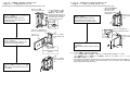
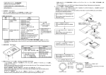
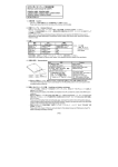
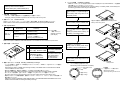
6. バッテリの装着 Installation of Battery
・ SRAM カードのバッテリは,電池ホルダからはずして出荷されていますので SRAM カードを使用するときは
下記手順によりバッテリをセットしてください。
Since the SRAM card is shipped without mounting a battery on a battery holder, set the battery according to
the following procedures when using the SRAM card.
QCPU 用メモリカード取扱説明書
Memory card manual for QCPU
Q3MEM-4MBS(-SET), Q3MEM-8MBS(-SET)
BCN-P5651-B
電池ホルダ固定スイッチをRELEASE位置にす
る
Set a battery holder fixing switch to the
RELEASE position
1. 注意事項 Precaution
・ メモリカード本体に記載されている注意事項をよくお読みください。
Thoroughly read the precautions printed on the main body of the memory card.
2. 詳細マニュアル Detailed Manual
QCPU ユーザーズマニュアル(ハードウェア設計・保守点検編)SH-080472 を参照してください。
Refer to QCPU User’s Manual (Hardware Design, Maintenance and Inspection) SH-080483ENG.
SRAMカードの電池ホルダをはずす
Pull out a battery holder of a SRAM card
電池ホルダ固定スイッチ
Battery holder fixing switch
RELEASE位置
RELEASE position
*1
+側
'+' side
3. 仕様 Specifications
種類
Type
形名
Model name
Q3MEM-□MBS
□ =4/8 *1
SRAM カード
SRAM card
Q3MEM-□MBS-SET
□ =4/8 *1
付属品
Accessory
・Q3EM-BAT バッテリ
Q3EM-BAT battery
・Q3EM-BAT バッテリ
Q3EM-BAT battery
・メモリカード保護カバー
Memory card protective cover
*1□=メモリ容量
(単位:M バイト)
Capacity of memory
(Unit: Mbyte)
バッテリの+面を上に向けて,電池ホルダに
セットする
Facing up a positive side of a battery, set
the battery on the battery holder
電池ホルダ
Battery holder
仕様の詳細は,詳細マニュアルの“メモリカード,バッテリ”の章を参照してください。
Refer to the chapter of "MEMORY CARD AND BATTERY" in the detailed manual for details of the specifications.
4. 各部の名称 Part Names
3)
1)
No.
Purpose
内容
1) 電池ホルダ部
Battery holder
2) 電池ホルダ固定スイッチ
Battery holder fixing switch
LOCK:固定,RELEASE:解除 LOCK: locked, RELEASE:
lock canceled
3) ライトプロテクトスイッチ
Write protect switch
This is set to “OFF” at the
工場出荷時は OFF 設定。
factory default setting.
ON:データの書込み禁止。
ON: Data read-only.
OFF:データの書込み許可。
OFF: Data writable.
2)
5. 取扱いおよびバッテリ交換 Handling and Battery Exchange
・ バッテリの交換は,SRAM カードの内容をバックアップしてから,SRAM カードを CPU ユニットに装着し
た状態で行ってください。
After backing up data in a SRAM card, exchange a battery of the SRAM card in a status where the SRAM
card is installed to the CPU module.
・ 電池ホルダ装着時は,電池ホルダ固定スイッチを必ず LOCK 位置に戻してください。
Be sure to set a battery holder fixing switch to the LOCK position when the battery holder is installed.
・ 本メモリカード使用時は,必ずメモリカード保護カバーを CPU ユニットに装着してください。
Be sure to set a memory card protective cover to the CPU module when using this memory card.
・ 取扱いおよびバッテリ交換の詳細は,詳細マニュアルの“メモリカード,バッテリ”および“保守点検”の
章を参照してください。
Refer to the chapter of "MEMORY CARD AND BATTERY" and "MAINTENANCE AND INSPECTION" in the
detailed manual for details of handling and battery exchange.
バッテリをセットした電池ホルダをSRAMカー
ドの奥までしっかり挿入する
Deeply insert the battery holder where
the battery is set into the SRAM card
電池ホルダ固定スイッチをLOCK位置にする
Set the battery holder fixing switch to the
LOCK position
LOCK位置
LOCK position
*1:バッテリの向きを下記に示します。
The following shows the direction of a battery.
メーカ名 Maker name
製造番号
(製造日によって異なります)
Manufacture number
(varies depending on date of manufacture)
形名 Model
極性 Polarity
電圧 Voltage
+側
'+' side
-側
'-' side
7. メモリカードの装着 Installation of Memory Card
8. メモリカードの取りはずし Removal of Memory Card
・大容量メモリカードの装着手順を下記に示します。
The following shows the procedures to install a large-capacity memory card.
・大容量メモリカードの取りはずし手順を下記に示します。
The following shows the procedures to remove a large-capacity memory card.
CPUユニット本体
CPU module main unit
CPU ユニットの電源を OFF して,CPU ユニット
本体のふたを取りはずす
Turn OFF power supply of the CPU
module and remove a lid of the CPU
module main body
ふたの中央付近をたわませ
て,取付け穴とリブの間に
隙間を作り,取りはずす。
Slightly bend the center of a
lid to make space between a
projection and a mounting
hole and remove the lid
リブ
Projection
上部と下部の固定爪を
押しながらはずす
Remove a cover,
pressing fixing claws
of top/bottom
CPU ユニットの電源を OFF して,メモリカード
保護カバーをはずす
Turn OFF power supply of the CPU
module and remove a memory card
protective cover from the CPU module
メモリカードEJECTボタン
Memory card EJECT button
メモリカードEJECTボタン
Memory card EJECT button
メモリカード
Memory card
CPUユニット本体
CPU module main
unit
押す
Push
メモリカードを CPU ユニット本体のメモリカー
ドスロットに装着する
Install a memory card to a memory card
slot of the CPU module main body
CPUユニット本体
CPU module main
unit
Set a memory card protective cover to the
CPU module
CPUユニット本体
CPU module main
unit
メモリカード EJECT ボタンを押してメモリカー
ドを引き出す
*挿入方向確認
(△マーク)
* Insertion direction check
(△mark)
メモリカード保護カバーを CPU ユニットに装着
する
CPUユニット本体
CPU module main
unit
Press the EJECT button to eject a memory
card
9. バッテリの廃棄
Disposal of batteries
・ バッテリを廃棄する際には各地域にて定められている法令に従い分別を行ってください。
(EU 加盟国内でのバッテリ規制についての詳細は,QCPU ユーザーズマニュアル(ハードウェア設計・
保守点検編)を参照してください。)
When disposing of batteries, separate them from other wastes according to the local regulations.
(For details of the battery directive in EU member states, refer to the QCPU User’s Manual (Hardware
Design, Maintenance and Inspection)).