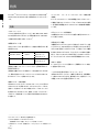
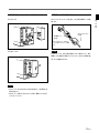
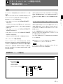
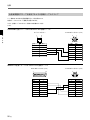
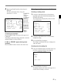
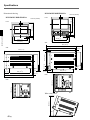
1
TRINITRON® COLOR VIDEO MONITOR BVM-D9H1J/D9H1U/D9H1E/D9H1A BVM-D9H5J/D9H5U/D9H5E/D9H5A BVM-D14H1J/D14H1U/D14H1E/D14H1A BVM-D14H5J/D14H5U/D14H5E/D14H5A 電気製品は、安全のための注意事項を守らないと、火災 や人身事故になることがあります。 このオペレーションマニュアルには、 事故を防ぐための重要な注意事項と製 品の取り扱いかたを示してあります。 このオペレーションマニュアルをよく お読みのうえ、製品を安全にお使いください。お読みになったあとは、いつ でも見られるように必ず保管してください。 OPERATION MANUAL [Japanese/English] 1st Edition (Revised 3) Serial No. 2000001 and Higher 警告 安全のために ソニーのモニターは正しく使用すれば事故が起きないように、安全には十分配慮 して設計されています。 しかし、内部に非常に高い電圧を使用しているので、 まち がった使いかたをすると、火災や感電などにより死亡や大けがなど人身事故につ ながることがあり、危険です。 事故を防ぐために次のことを必ずお守りください。 安全のための注意事項を守る 3(J)∼6(J)ページの注意事項をよくお読みください。製品全般の安全上の注意事 項が記されています。7(J)ページの 「使用上のご注意」 もあわせてお読みください。 定期点検をする 5年に1度は、内部の点検を、お買い上げ店またはソニーのサービス窓口にご依頼 ください(有料) 。 故障したら使わない このオペレーションマニュアル および製品では、次のような表 示をしています。表示の内容を よく理解してから本文をお読み ください。 警告 この表示の注意事項を守らない と、火災や感電などにより死亡 や大けがなど人身事故につなが ることがあります。 注意 すぐに、お買い上げ店またはソニーのサービス窓口にご連絡ください。 万一、異常が起きたら ・煙が出たら ・異常な音、においがしたら ・内部に水、異物が入ったら ・モニターを落としたり キャビネットを破損した ときは 警告表示の意味 / 1 電源を切る。 2 電源コードや接続ケーブルを 抜く。 3 お買い上げ店またはソニーの サービス窓口に連絡する。 この表示の注意事項を守らない と、感電やその他の事故により けがをしたり周辺の物品に損害 を与えたりすることがありま す。 注意を促す記号 注意 火災 感電 高温 行為を禁止する記号 ぬれ手禁止 この装置は、情報処理装置等電波障害自主規制協議会(VCCI)の基準に 基づくクラスA情報技術装置です。この装置を家庭環境で使用すると電 波妨害を引き起こすことがあります。 この場合には使用者が適切な対策 を講ずるよう要求されることがあります。 分解禁止 禁止 行為を指示する記号 強制 プラグをコン セントから抜く 目次 警告 .............................................................................................................. 3(J) 注意 .............................................................................................................. 4(J) 電池についての安全上のご注意 ......................................................................... 6(J) 使用上のご注意 .................................................................................................. 7(J) 特長 .................................................................................................................... 8(J) 第 1 章 概要 特長 ........................................................................................................................ 8(J) 別売り品 ................................................................................................................. 9(J) 各部の名称と働き ............................................................................................ 11(J) BVM-D9H1J/D9H5J モニター前面 ................................................................... 11(J) BVM-D9H1J/D9H5J モニター後面 ................................................................... 16(J) BVM-D14H1J/D14H5J モニター前面 ............................................................... 20(J) BVM-D14H1J/D14H5J モニター後面 ............................................................... 25(J) 4:3マスクの取り付け ....................................................................................... 28(J) BVM-D9H1J/D9H5J の場合 .............................................................................. 28(J) BVM-D14H1J/D14H5J の場合 .......................................................................... 28(J) メニューの操作方法 ......................................................................................... 29(J) 第2 章 メニュー メニュー操作ボタン ............................................................................................. 29(J) メニューリストを表示させるには .......................................................................... 30(J) メニューの操作手順 ............................................................................................ 31(J) ADDRESSメニューについて ............................................................................. 33(J) メニューの階層構造 ......................................................................................... 34(J) A 画像調整つまみのプリセット調整 ーCONTROL PRESET ADJメニュー .............................................. 35(J) 概要 ...................................................................................................................... 35(J) CONTROL PRESET ADJメニューの階層構造 ................................................ 35(J) 構成メニュー........................................................................................................ 35(J) B 色温度の調整ーCOLOR TEMP ADJメニュー ....................................... 37(J) 概要 ...................................................................................................................... 37(J) COLOR TEMP ADJメニューの階層構造 ......................................................... 37(J) 構成メニュー........................................................................................................ 38(J) C 入力チャンネルの設定 ーINPUT CONFIGメニュー ............................... 39(J) 概要 ...................................................................................................................... 39(J) INPUT CONFIGメニューの階層構造 .............................................................. 39(J) 構成メニュー........................................................................................................ 40(J) D リモートコントロール機能の設定 ーREMOTEメニュー ......................... 41(J) 概要 ...................................................................................................................... 41(J) REMOTEメニューの階層構造 .......................................................................... 41(J) (続く) 構成メニュー........................................................................................................ 42(J) 1 (J) 日 本 語 目次 第2章 メニュー E 電源投入時の状態、画面表示状態などの設定 ーSYSTEM CONFIGメニュー ......................................................... 43(J) 概要 ...................................................................................................................... 43(J) SYSTEM CONFIGメニューの階層構造 ........................................................... 44(J) 構成メニュー........................................................................................................ 44(J) F モニターに関する情報の表示 ーSTATUSメニュー ................................. 46(J) 概要 ...................................................................................................................... 46(J) STATUSメニューの階層構造 ............................................................................ 46(J) 構成メニュー........................................................................................................ 46(J) G 画像のサイズ、位置、画ひずみの調整 ーALIGNMENTメニュー ........... 47(J) 概要 ...................................................................................................................... 47(J) ALIGNMENTメニューの階層構造 .................................................................. 47(J) 構成メニュー........................................................................................................ 47(J) 操作するモニターを選択するーADDRESSメニュー .................................... 48(J) 概要 ...................................................................................................................... 48(J) ADDRESSメニューの構成と使いかた .............................................................. 48(J) リモート操作状態を解除するには ....................................................................... 49(J) ADDRESSメニューを消すには .......................................................................... 49(J) アドレスショートカット機能について ..................................................................... 49(J) 第 3 章 付録 仕様 .................................................................................................................. 50(J) 対応信号フォーマット........................................................................................... 55(J) 色温度調整用プローブを使用するときの接続ケーブルについて .................... 56(J) メニュー項目索引 ............................................................................................ 58(J) メニュー階層構造 ............................................................................................ 60(J) 2 (J) 警告 下記の注意を守らないと、 火災 感電 火災や感電により死亡や大けがにつながることがあります。 内部を開けない、改造しない 分解禁止 内部には電圧の高い部分があり、 キャビネッ トや裏ぶたを開けたり、改造したりすると、火 災や感電の原因となります。内部の調整や 設定、点検、修理は、お買い上げ店またはソ ニーのサービス窓口にご依頼ください。 油煙、湯気、湿気、ほこりの多い場所では設置・ 使用しない 禁止 上記のような場所に設置すると、火災や感 電の原因となります。 取扱説明書に記されている仕様条件以外 の環境での使用は、火災や感電の原因とな ります。 内部に水や異物を入れない 禁止 水や異物が入ると火災や感電の原因となり ます。 万一、水や異物が入ったときは、すぐに電源 を切り、電源コードや接続ケーブルを抜い て、お買い上げ店またはソニーのサービス 窓口にご相談ください。 電源コードを傷つけない 禁止 電源コードを傷つけると、火災や感電の原 因となります。 • 設置時に、製品と壁やラック、棚などの間 に、はさみ込まない。 • 電源コードを加工したり、傷つけたりしな い。. • 重いものをのせたり、引っ張ったりしな い。 • 熱器具に近づけたり、加熱したりしない。 • 電源コードを抜くときは、必ずプラグを 持って抜く。 万一、電源コードが傷んだら、お買い上げ店 またはソニーのサービス窓口に交換をご依 頼ください。 水のある場所に設置しない 水が入ったりぬれたりすると、火災や感電 の原因となることがあります。雨天や降雪 中、海岸や水辺での使用は特にご注意くだ さい。 ラックマウント時は専用ブレーカーを取り付 ける ラックマウント時は前面より電源を切ること ができません。設置の際は専用ブレーカー を取り付けて使用してください。 強制 AC アダプターを他の機器に使用しない 禁止 付属のACアダプターは、BVM-D9H1J/ D9H5J専用のアダプターです。 他の機器に使用すると、火災や感電の原因 となります。 規定の電源電圧で使う 強制 取扱説明書に記されている電源電圧でお 使いください。 DC (直流) 電源で動作できるモニターは、取 扱説明書に記されている電源アダプターあ るいはバッテリーパックでお使いください。 規定外の電源電圧での使用は、火災や感 電の原因となります。 3 (J) 下記の注意を守らないと、 注意 けがをしたり周辺の物品に損害を与えることがあります。 ぬれた手で電源プラグをさわらない ぬれた手で電源プラグを抜き差しすると、 感電の原因となることがあります。 直射日光の当たる場所や熱器具の近くに設置・ 保管しない ぬれ手禁止 禁止 接続の際は電源を切る 電源コードや接続ケーブルを接続するとき は、電源を切ってください。 さもないと感電や 故障の原因となることがあります。 重いモニターは、 2 人以上で開梱・運搬する 注意 指定された電源コード、接続ケーブルを使う 注意 付属の、 あるいは取扱説明書に記されてい る電源コード、接続ケーブルを使わないと、 感電や故障の原因となることがあります。 他の電源コードや接続ケーブルを使用する 場合は、お買い上げ店またはソニーのサー ビス窓口にご相談ください。 注意 注意 不安定な場所に設置しない 禁止 4 (J) ぐらついた台の上や傾いたところなどに設 置すると、モニターが落ちたり、倒れたりし て、 けがの原因となることがあります。 また、 設置・取り付け場所の強度を充分にお確か めください。 モニターは見た目より重量があります。開梱 や運搬は、 けがや事故を防ぐため、必ず2人 以上で行ってください。1人で行うと腰を痛 めることがあります。 通風孔をふさがない 禁止 バッテリーパックは確実に取り付ける 本機にAC/DC電源やリチウムイオンバッテ リーパックを取り付けるときは、 この取扱説明 書の該当する箇所をよく読んだうえ確実に 取り付けてロックしたことを確認してくださ い。取り付け方法を誤ると落下してけがをす ることがあります。 内部の温度が上がり、火災や故障の原因と なることがあります。 真夏の、窓を閉め切った自動車内では50℃ を越えることがありますので、 ご注意くださ い。 通風孔をふさぐと内部に熱がこもり、火災や 故障の原因となることがあります。風通しを よくするために次の項目をお守りください。 • 壁から10cm以上離して設置する。 • 密閉された狭い場所に押し込めない。 • 毛足の長い敷物(じゅうたんや布団など) の上に設置しない。 • 布などで包まない。 • あお向けや横倒し、逆さまにしない。 転倒、移動防止の処置をする 注意 モニターをラックに取り付け・取りはずしする ときは、転倒・移動防止の処置をしないと、 倒れたり、動いたりして、 けがの原因となる ことがあります。 安定した姿勢で注意深く作業してください。 また、 ラックの設置状況、強度を充分にお確 かめください。 モニターの上に乗らない、重い物を乗せない 倒れたり、落ちたり、壊れたりして、 けがの原 因となることがあります。 禁止 基板を取り付けの際は電源を切る このマニュアルで説明している各種アダ プター (拡張ボード) をビデオモニターのス ロットに取り付けるときは、 ビデオモニター の電源を切ってください。 さもないと感電 プラグをコン や故障の原因となることがあります。 セントから抜く お手入れの際は、電源を切って電源プラグを 抜く 基板の取り付けは注意深く 電源を接続したままお手入れをすると、感 電の原因となることがあります。 プラグをコン セントから抜く 注意 このマニュアルで説明している各種アダプ ター (拡張ボード) をビデオモニターのスロッ トに取り付けるときは、部品や基板などの角 で、手や指にけがをしないように注意深く作 業してください。保護手袋をして作業するこ とをおすすめします。 移動させるときは電源コード、接続ケーブル を抜く 接続したまま移動させると、電源コードや接 続ケーブルが傷つき、火災や感電の原因と なることがあります。 注意 定期的に内部の掃除を依頼する 注意 長い間掃除をしないと内部にホコリがたま り、火災や感電の原因となることがあります。 1年に1度は、内部の掃除をお買い上げ店ま たはソニーのサービス窓口にご依頼くださ い(有料) 。 特に、湿気の多くなる梅雨の前に掃除をす ると、 より効果的です。 スタンドの開閉時にはロックを確認する 注意 スタンドの開閉時には、スタンドがロックした のを確認してから本機をおろしてください。 確認しないと指や手をはさみけがの原因と なることがあります。 5 (J) 電池についての安全上のご注意 ここでは、本機での使用が可能なソニー製リチウム電池についての注意事項を記 載しています。 万一、異常が起きたら , 1 機器の電源スイッチを切る。 煙が出たら 2 ソニーのサービス担当者に連絡する。 電池の液が目に入ったら , すぐにきれいな水で洗い、ただちに医師の治療を受ける。 電池の液が皮膚や衣服に付いたら , すぐにきれいな水で洗い流す。 バッテリー収納部内で液が漏れたら , よくふき取ってから、新しい電池を入れる。 危険 破裂 警告 下記の注意事項を守らないと、破裂・発火・発熱・液漏れにより、死亡や大けがに なることがあります。 高温 • 火中に投入、加熱、はんだ付けをしない。 • 分解、改造をしない。 • 直射日光の当たるところ、炎天下の車 、ストーブのそばなど高温の場所で、使用・放置・充電をしない。 • ハンマーでたたくなどの強い衝撃を与えたり、踏みつけたりしない。 • 接点部や3極と#極をショートさせたり、金属製のものと一緒に携帯・保管をし ない。 下記の注意事項を守らないと、破裂・発火・発熱・液漏れにより、死亡や大けがな どの人身事故になることがあります。 • 電池使用中や保管時に異臭がしたり、発熱・液漏れ・変色・変形などがあった ときは、すぐに使用や充電をやめ、火気から遠ざける。 破裂 6 (J) 高温 使用上のご注意 (モニターの性能を保持するために) 磁気に対するご注意 • 磁石、スピーカー、電気時計、磁石を使用した機器やおもちゃ、磁気応用健康器 具など、磁気を発生するものを近づけないでください。磁気の影響を受けて、画 面が揺れたり、色が乱れたりすることがあります。 • モニターの設置の向きによっては、地磁気の影響を受けて、画面が傾いたり、色 が乱れることがありますが、故障ではありません。 このときは、モニターコントロール ユニットのDEGAUSS(消磁)ボタンを押して消磁してください。 ラックに収納する場合のご注意 モニターをラックに収納した場合、他の機器の発熱や通気量の減少によりモニター の周囲温度が上昇し、故障の原因となることがあります。 したがってモニターを収 納する場合は、通気孔の確保や通気ファンの設置などにより、周囲温度を定められ た動作温度範囲内に適合させるための配慮が必要です。 (動作温度範囲:0∼35℃、推奨使用温度範囲:20∼30℃) ブラウン管について • ブラウン管の表面はほこりが付きやすいので、ときどき柔らかい布でふいてくだ さい。 また、表面は傷つきやすいので、硬いものでこすったり、たたいたり、 ものを ぶつけたりしないでください。 これはブラ • ブラウン管の表面に手を触れると弱い電気を感じることがありますが、 ウン管表面に静電気を帯びているためで、人体に影響はありません。 クリーニングについて • お手入れの際は、必ず電源を切って電源プラグを抜いてください。 • キャビネットの汚れがひどいときは、水で5∼6倍に薄めた中性洗剤液に柔らかい 布をひたし、かたくしぼってから汚れをふきとります。 このあと乾いた布でからぶ きしてください。 • シンナーやベンジンなどの薬品類は、表面の仕上げをいためたり、表示が消えて しまうことがありますので、使用しないでください。 4:3 信号用のモニターとしてお使いになるときのご注意 本機には出荷時に16:9マスクが取り付けてあるため、本機の16:9ボタンを操作して 4:3アスペクト表示にすると、画像の上部と下部がマスクに隠れて見えません。4:3ア スペクト比で表示するときは、 あらかじめ付属の4:3マスクに交換してからお使いく ださい。 ◆ 詳しくは、 「4:3 マスクの取り付け」 (28(J)ページ)をご覧ください。 バッテリー使用時のご注意(BVM-D9H1J/D9H5J) BVM-D9H1J/D9H5Jは、主電源 (Main Power)スイッチを持たないため、バッテリー を取り付けた状態で電源をオフにするとスタンバイモードになります。 このスタンバ イモードでは、わずかですが電力を消費し続けますので、モニターを長時間ご使用 にならないときは、バッテリーを取りはずして保管してください。 7 (J) 特長 トリニトロン®1)カラービデオモニターBVM-D9H1J/D9H5Jは9型2)、 第 準装備 です。 デコーダーのクロマやフェーズを自動調整するオートクロマ・フェー 1 章 概 要 オートクロマ・フェーズ、オートホワイトバランス機能を標 BVM-D14H1J/D14H5Jは 14 型 の業務用カラービデオモニター 2) ズ機能と別売りのオートセットアッププローブBKM-14Lなどを使用 し、色温度を自動調整するオートホワイ トバランス機能を標準装備し 特長 ています。 マルチフォーマット 4:3エリアマーカーを標準装備 デジタル放送時代の主要フォーマット(480I/480P/720P/1080I) および従来のNTSC、PALなど、水平周波数15kHz∼45kHzまで 16:9 画像内の 4:3アスペクトエリアを容易に確認するためにマー カーを表示できます。 の多様な信号に幅広く対応しています 3)。 拡張可能な入力機能 高解像度ブラウン管 本機後面の入力オプションスロットに別売りの入力アダプターを差 HRトリニトロンブラウン管の採用により、高密度で鮮明なカラー画 し込んだだけで、HD SDI信号やD1 SDI信号、NTSC/PAL信号、 像が得られます。 YPBPR/RGB 信号を入力することができ、入力端子パネルの構成 モデル名 AGピッチ BVM-D9H1J/D9H5J 0.25mm BVM-D14H1J/D14H5J 0.25mm 中心解像度 を自由に変えることができます。入力アダプターは3枚まで装着で 450 TV 本(4:3) きます。スロット1にはYPBPR/RGB信号を入力できるアナログコン 340 TV 本(16:9) ポーネント入力アダプターBKM-129Xが標準装備されています。 800 TV 本(4:3) 600 TV 本(16:9) 安定した色温度 ビームカレントフィードバック回路により、長期間にわたって安定し 操作部を分離したオペレーションスタイル (BVM-D9H1J/ た色温度が得られます。 BVM-D14H1J) 操作部を分離することにより設置スペースを削減することができま ノイズ成分の監視に便利なブルーオンリーモード す。操作は別売りのモニターコントロールユニットBKM-10R/11R、 3系統のCRT のカソードをすべて青信号で動作させ、白黒画像と またはディジーチェーン接続により行います。 して表示させることができます。飽和度(クロマ)や色相(フェーズ) の調整、VTRノイズの監視に便利なモードです。 複数のモニターを統括管理 RS-485シリアルリモートにより、1台のコントロールユニットで最大32 台までのモニターを操作できます。アドレスNo.やグループNo.を 指定して、特定のモニターまたは特定のグループのモニターだけ を操作することができます。また、接続しているすべてのモニター のセットアップ状態を統一したり、同時に同じ動作を実行させること も可能です。 ................................................................................................................................................................................................................................ 1)トリニトロン® はソニー株式会社の登録商標です。 2) それぞれ搭載されているCRT のサイズです。 有効画面サイズは「仕様」 (50(J)ページ)を参照してください。 3) 対応するフォーマットは「対応信号フォーマット」 (55(J)ページ)を参照してくだ さい。 8 (J) 第 1 その他の特長 章 概 第 要 1 別売り品 • モニターの各種機能や動作条件を、画面に表示されるメニューで 設定できます。 操作部関連 • リモート端子として、RS-485シリアルリモートと接点制御のパラレル リモートの両方を装備。 • 水平、垂直同期信号を同時に監視できるHディレイ、Vディレイ機 能。VITS(Vertical Interval Test Signal)の監視も可能。 • オートデガウス、マニュアルデガウス機能。 モニターコントロールユニットBKM-10R BVM-D9H1Jおよび BVM-D14H1J の外部コントロールユニットで す。1台で複数台のモニターを同時にコントロールすることができま す。 • 別売りのマウンティングブラケットMB-520(9型モニター用)やラッ クマウントキットBKM-30E14/31E14(14 型モニター用)の使用に より、EIA 規格の 19インチラックにマウント可能。 • 用途に応じて 16:9 映像用と4:3 映像用のマスクを交換可能。 • ソニーリチウムイオンバッテリー(BP-L60A/L90A)または外部 DC 12V 電源により動作可能。 (BVM-D9H1J/D9H5J のみ) • 音声再生回路とスピーカーを内蔵。 (BVM-D9H5J のみ) モニターコントロールユニットBKM-11R 本機や他のBVM/HDMシリーズのビデオモニターを操作するた めのコントロールユニットです。1台で複数台のモニターを同時にコ ントロールすることができます。 オートセットアッププローブBKM-14L このプローブにより、本機の色温度の自動調整ができます。 設置用 マウンティングブラケットMB-520 BVM-D9H1J/D9H5JをEIA規格の19インチラックに収納するため の組み立てキットです。 マウンティングパネルMB-519 BVM-D9H1JをMB-520に1 台ラックマウントしたときに片側に空く スペースをふさぐためのパネルです。 マウンティングパネルMB-509 BVM-D9H5JをMB-520に1 台ラックマウントしたときに片側に空く スペースをふさぐためのパネルです。 ラックマウントキットBKM-30E14 BVM-D14H5JをEIA規格の19インチラックに収納するための組み 立てキットです。 ラックマウントキットBKM-31E14 BVM-D14H1JをEIA規格の19インチラックに収納するための組み 立てキットです。 その他 モニターENGキットVF-508 BVM-D9H1J/D9H5J用の遮光フードとコネクタープロテクターの組 み立てキットです。 9 (J) 章 概 要 特長 入力アダプター 本機後面の入力オプションスロット (3スロット) に装着して、入出力 第 1 章 概 要 端子パネルを構成します。3 枚まで装着できます。 各入力アダプターで入出力する信号の種類は、入出力端子パネル の構成に応じてINPUT CONFIGメニューで選択します。 ご注意 入力アダプターを装着したときは、INPUT CONFIGメニューで、 入力チャンネルの設定を行ってください。設定を行わないと装着し た入力アダプターが正しく動作しないことがあります。 ◆ INPUT CONFIGメニューについては、 「[C] 入力チャンネルの設定− INPUT CONFIGメニュー」 (39(J)ページ)をご覧ください。 SDI 4:2:2入力アダプターBKM-120D シリアルデジタルコンポーネント信号用のデコーダーアダプターで す。 D1 SDI 入力 2 系統、アクティブスルー出力 2 系統を装備していま す。 NTSC/PAL入力アダプターBKM-127W アナログコンポジット信号(NTSC/PAL)用のデコーダーアダプ ターです。 コンポジットビデオ入出力2系統、Y/C入出力1系統を装備してい ます。 アナログコンポーネント入力アダプターBKM-129X アナログ RGB/アナログコンポーネント用のアダプターで入出力 1 系統、EXT SYNC 入出力 1 系統を装備しています。 ◆ BKM-129Xはモニター本体に 1 枚標準装備しています。 HD SDI 入力アダプターBKM-142HD HDシリアルデジタル信号用のデコーダーアダプターです。シリア ルデジタル信号入力端子を2系統、モニターアウト端子を1系統装 備しています。 ご注意 • BKM-142HDは入力スロットを2 枚分使用します。 • BKM-142HD のMONITOR OUT 出力は、本線系としての出力 規格を満足していません。 10 (J) 各部の名称と働き BVM-D9H1J/D9H5Jモニター前面 BVM-D14H1J/D14H5Jについては 20(J)ページから24(J)ページをご覧ください。 第 BVM-D9H5J 章 概 要 1 8 キャリングハンドル 1 タリーランプ 2 STANDBYランプ 9 OPTION 端子 3 POWERランプ 0 VOLUMEつまみ 4 DEGAUSSボタン !¡ MANUAL調整つまみ !™ SHIFTボタン 5 POWERスイッチ !£ ファンクションボタン 6 Entボタン !¢ メニュー操作ボタン 7 テンキー部 !∞ スタンド BVM-D9H1J 8 キャリングハンドル 1 タリーランプ 2 STANDBYランプ 9 OPTION 端子 3 POWERランプ 11 (J) 各部の名称と働き 第 下記はBVM-D9H5Jのコントロールパネルを例に説明してあります 4 DEGAUSS(消磁)ボタン が、モニターコントロールユニットBKM-10R/11Rを接続した場合も 押すとCRTが消磁されます(本機の電源を入れるたびに、CRTは 各機能および名称は共通です。 自動的に消磁されます)。再度消磁するときは、5分以上間隔をお 1 章 概 要 いてください。 1 タリーランプ 出荷時の設定では、PARALLEL REMOTE 1 端子(後面)のピン 5 POWER(電源)スイッチ をショートさせるとタリーランプは次のように点灯します。 押すたびに本機の電源を入/切します。モニターを複数台接続し - No.3ピンとNo.9ピンをショートさせたとき、赤く点灯。 ているときは、ADDRESSメニューの設定により、指定したモニ - No.4ピンとNo.9ピンをショートさせたとき、緑に点灯。 ターの電源だけを入/切したり、全モニターの電源を同時に入/切 - No.3ピン、No.4ピンとNo.9ピンをショートさせたとき、オレンジに することができます。 点灯。 PARALLEL REMOTE 2 端子(後面)のピンをショートさせるとタ リーランプは次のように点灯します。 - No.3ピンとNo.5ピンをショートさせたとき、赤く点灯。 - No.4ピンとNo.5ピンをショートさせたとき、緑に点灯。 - No.3ピン、No.4ピンとNo.5ピンをショートさせたとき、オレンジに 点灯。 REMOTEメニューの設定により、PARALLEL REMOTE 端子の 別のピンをタリー用に使うこともできます。 ◆ ADDRESSメニューについては、 「操作するモニターを選択する− ADDRESSメニュー」 (48(J)ページ)をご覧ください。 6 Entボタン 入力した数値や文字を確定したり、選択した項目および設定値を 確定します。 7 テンキー部 モニターしたい入力信号のチャンネル番号を指定したり、 メニュー で設定値を入力するときに使います。 ◆ REMOTEメニューについては、 「[D]リモートコントロール機能の設定− REMOTEメニュー」 (41(J)ページ)をご覧ください。 Delボタン:入力した数値や 2 STANDBY(スタンバイ)ランプ 1 2 3 Del 4 5 6 0 7 8 9 Ent 本機がスタンバイ状態のとき点灯します。 本機がスタンバイ状態になるのは以下の場合です。 文字を消去します。 数値ボタン • SYSTEM CONFIGメニューのSTANDBY MODEがONに設定 された状態で、電源やバッテリーを装備したとき • 外部操作により、本機を動作状態からスタンバイ状態に切り換え たとき ◆ SYSTEM CONFIGメニューについては、 「[E] 電源投入時の状態、画 面表示状態などの設定−SYSTEM CONFIGメニュー」(43(J)ページ) をご覧ください。 8 キャリングハンドル モニターを持ち運ぶとき引き出して使用します。 9 OPTION(オプション)端子 3 POWER(電源)ランプ モニターコントロールユニットBKM-11Rまたは、オートセットアップ 本機がスタンバイ状態のとき(2 STANDBYランプ参照)、POWER プローブ(BKM-14Lなど)を接続します。 スイッチ 5を押して本機を動作状態にすると点灯します。 ご注意 0 VOLUMEつまみ STANDBYランプ2が点滅している間は、本機を動作状態にする 後面のAUDIO IN端子に接続した機器からの音声信号の音量を ことはできません(内部データの初期化を実行中です)。STANDBY 調整します。 ランプ 2が点灯するまでお待ちください。 12 (J) !¡ MANUAL(手動)調整つまみ !£ ファンクションボタン つまみを押すたびに、つまみ上のLED (緑)がついたり(ON)、消 モニターの動作条件を切り換えます。 えたり(OFF)します。ONにすると、画面のコントラスト、明るさ(黒レ 押すたびに、ボタン上のLEDがついたり(ON)、消えたり(OFF)し ベル)、クロマ(色の飽和度)、フェーズ(色相)を調整できます。ま て、モニターの動作条件が切り換わります。 た、 メニューで項目を選択したり設定値を入力するときにも使いま 各ボタンには2種類の機能が割り付けられています。SHIFTボタン す。 !™をON/OFFして、どちらの機能を使うか選択します。シフトOFF 各調整項目は、CONTROL PRESET ADJメニューでプリセット値 の場合は、各ボタンのLEDの色が緑に、シフトONの場合は、各ボ を設定しておくことができます。 タンのLEDの色がオレンジになります。 (シフトOFFの場合:14(J) 1 ページ参照。シフトON の場合:15(J)ページ参照。) ◆ CONTROL PRESET ADJメニューについては、 「A 画像調整つまみ のプリセット調整−CONTROL PRESET ADJメニュー」 (35(J)ページ)を ご覧ください。 !¢ メニュー操作ボタン MENUボタン:押すとメニューが表示 PHASE (フェーズ) CHROMA BRIGHT (クロマ) (明るさ) CONTRAST (コントラスト) 調整つまみ 調整つまみ 調整つまみ 調整つまみ MENU UP されます。 UP/DOWNボタン:項目および設定値 を選択します。 DOWN PHASE CHROMA BRIGHT CONTRAST ◆ メニューの操作について詳しくは、 「メニューの操作方法」 (29(J)ページ) をご覧ください。 !∞ スタンド 引き出して使用します。 ご注意 PHASE 調整つまみとCHROMA調整つまみは、一部の入力信号 キャリングハンドルとスタンドの使いかた では使用しませんが、 メニューでの項目の選択や設定値の入力に は使用できます。 上に引き出す。 !™ SHIFT(シフト)ボタン このボタンを押して、ファンクションボタン!£に割り付けられている 2 種類の機能のうちどちらを使うか選択します。 押すたびに、SHIFTボタン上の LEDがオレンジ色に点灯(シフト ON)したり、消灯(シフトOFF)したりします。 シフトOFFのとき:各ファンクションボタンの上側に表示されて いる機能が使えます。 (ファンクションボタンのLEDが緑色に点 灯) シフトONのとき:各ファンクションボタンの下側に表示されてい る機能が使えます。 (ファンクションボタンのLEDがオレンジ色 第 前に出す。 に点灯) 13 (J) 章 概 要 各部の名称と働き シフトOFFの場合(緑のLED) 第 (アンダースキャン)ボタン:ONにすると、3%アン ダースキャンになり、ラスターの四隅までが画面に表示 されます。 1 章 概 要 (Hディレイ)ボタン:ONにすると、画像が水平方向に移 動し、画面の左から約1/4の位置に水平同期信号が現わ れます。 • 画像の明るさ(輝度)が自動的に増加して、同期部分の チェックに便利です。 ボタンと同時に押すと、パルスクロス画像が表示さ • れます。 (Vディレイ)ボタン:ONにすると、画像が垂直方向に移 動し、画面のほぼ中央に垂直同期信号が現われます。 • 画像の明るさ(輝度)が自動的に増加して、同期部分の チェックに便利です。 ボタンと同時に押すと、パルスクロス画像が表示 • されます。 MONO(白黒)ボタン:ONにすると、画面が白黒になりま す。OFFにすると、カラーに切り換わります。 MONO 16:9 SYNC B ONLY R APT G COMB B F1 F3 F2 ADDRESS F4 MARKER ご注意 •RGB信号受信時には白黒になりません。 • NTSC、PAL信号受信時にはカラーバースト信号が無 い入力はカラーになりません。 ADDRESS(アドレス)ボタン:ONにすると、画面に ADDRESSメニューが表示されます。ADDRESSメ ニューを使って、複数のモニターを操作するときの動作 条件を設定します。 ◆ ADDRESSメニューについて詳しくは、 「操作するモニター を選択する− ADDRESSメニュー」 (48(J)ページ)をご覧く ださい。 F2ボタン:F2ボタンにCOLOR TEMP ADJメニューの第1 階層MANUALメニューへのショートカットが割り付け られていた場合、ONにするとMANUALメニューが表 示されます。 F1ボタン:ONにすると、CONTROL PRESET ADJメ ニューの第1階層MANUALメニュー上、COLOR TEMP ADJメニューの第1階層MANUALメニュー上、 およびALIGNMENTメニュー上での調整時、モニター 画面の文字を表示したり消したりします。 COMB(コム型フィルター)ボタン:本機では機能しません。 別売りのBKM-127W NTSC/PAL入力アダプターを装着 し、NTSCまたはPAL信号を入力すると自動的にコム フィルターが働いた状態で動作します。 APT(アパーチャー)ボタン:ONにすると周波数特性を補正 できます。補正量はメニューで設定します。 (RGB信号入力時は動作しません。) 14 (J) シフトONのとき(オレンジのLED) 16:9ボタン:ONにすると画面のアスペクト比が16:9に、 OFFにすると4:3になります。 ご注意 アスペクト比4:3に対応していない信号フォーマットの ときアスペクト比は16:9に固定されます。 ◆ 対応信号フォーマットについては55(J)ページをご 覧ください。 SYNC(シンク)ボタン:ONにすると、BKM-129Xの SYNC端子に入力されている同期信号に同期します (EXT SYNC)。OFFにすると、モニターしている信号 に含まれている同期信号に同期します(INT SYNC)。 ご注意 •INT SYNCを選択した場合、コンポーネント信号を モニターするときは、Y信号に同期信号を付加してく ださい。RGB信号をモニターするときは、G信号に 同期信号を付加してください。 •BKM-129Xが装着されていないときや、シリアルデ ジタル信号をモニターするときは、自動的にINT SYNCに切り換わります。EXT SYNCを選択するこ とはできません。 B ONLY(ブルーオンリー)ボタン:ONにすると、赤と緑 の信号がカットされ、青信号のみが白黒画像として表 示されます。クロマやフェーズの調整、VTRノイズの チェックに便利です。 R/G/Bボタン:ONにすると、R(赤 )、G(緑 )、B(青 )の ビームをカットします。 MONO APT COMB F1 F2 ADDRESS MARKER(マーカー)ボタン:ONにすると4:3エリア 16:9 SYNC B ONLY R G B F3 F4 MARKER マーカーが表示されます。 アスペクト比4:3の場合のエリアを参考にすることが できます。 ご注意 4:3 エリアマーカーはアスペクト比 4:3 の信号をモニターし ているときは表示されません。また、H/Vディレイモードのと きは表示されません。 F3/F4ボタン:将来の拡張用です。 15 (J) 第 1 章 概 要 各部の名称と働き BVM-D9H1J/D9H5Jモニター後面 第 BVM-D14H1J/D14H5Jについては 25(J)ページから27(J)ページをご覧ください。 1 章 概 要 BVM-D9H5J 6 入力オプションスロット 1 PARALLEL REMOTE1/2端子 2 DC 12V INジャック 7 アナログ入出力端子 3 EJECTボタン 4 ACアダプター/バッテリー 取り付け部 5 SERIAL REMOTE端子 8 AUDIO IN/OUT端子 BVM-D9H1J 6 入力オプションスロット 1 PARALLEL REMOTE1/2端子 2 DC 12V INジャック 7 アナログ入出力端子 3 EJECTボタン 4 ACアダプター/バッテ リー取り付け部 5 SERIAL REMOTE端子と SERIAL REMOTE/CTRL UNIT切り換えスイッチ 16 (J) 1 PARALLEL REMOTE 1/2 (パラレルリモート1/ 2 DC 12V INジャック(XLR型、4ピン) 2)端子(1 : D-sub 9ピン、メス 2 : モジュラーコネク 外部電源 DC 12Vを接続することにより、本機を動作させることが ター) できます。 第 1 パラレルコントロールスイッチを構成してモニターを外部操作しま す。ピン配置と出荷時の各ピンへの機能の割り付けは以下のとお 3 EJECTボタン りです。 このボタンを押しながらACアダプターやバッテリーを取りはずしま 1 : D-sub 9ピン す。 5 1 4 ACアダプター/バッテリー取り付け部 ACアダプターやバッテリーを取り付けます。 9 6 ピン番号 機 能 1 入力信号チャンネル 1を指定(テンキーの機能) 2 入力信号チャンネル 2を指定(テンキーの機能) 3 タリーランプ赤の ON/OFF 4 タリーランプ緑の ON/OFF 5 同期信号の選択(SYNCボタンの機能) 6 アンダースキャンするかどうかの選択 7 アスペクト比を16:9にするかどうかの選択 8 4:3 エリアマーカーを表示するかどうかの選択 9 GND (続く) 2 : モジュラーコネクター 1 6 ピン番号 機 能 1 入力信号チャンネル 1を指定(テンキーの機能) 2 入力信号チャンネル 2を指定(テンキーの機能) 3 タリーランプ赤のON/OFF 4 タリーランプ緑のON/OFF 5 GND 6 アンダースキャンするかどうかの選択 各ピンへの機能の割り付けは、REMOTEメニューで変更できま す。 ◆ REMOTEメニューについては、 「[D]リモートコントロール機能の設定− REMOTEメニュー」 (41(J)ページ)をご覧ください。 以下のようにピンの設定を変えて、各機能のON/OFFや有効/無 効を切り換えます。 ON または有効:D-sub 9ピンは各ピンと9ピンをショートさせる。 モジュラーコネクターは各ピンと5ピンをショートさせる。 OFF または無効:各ピンをオープンにする。 17 (J) 章 概 要 各部の名称と働き 5 SERIAL REMOTE (シリアルリモート)端子(D-sub 9 第 1 章 概 要 6 入力オプションスロット(3スロット) ピン、メス)とSERIAL REMOTE/CTRL UNIT切り換 別売りの入力アダプターを3 枚まで入れることができます。 えスイッチ(BVM-D9H1Jのみ) 出荷時はスロット1にBKM-129Xが取り付けられています。 BVM/HDMシリーズのモニターを2 台以上接続するための、RS485シリアルインターフェースです。IN端子とOUT端子はループス ルーになっています。 BVM-D9H1J のみ:SERIAL REMOTE/CTRL UNIT 切り換えス イッチは出荷時は SERIAL REMOTE 側に設定されています。 ご注意 • BKM-142HDは、入力オプションスロットを2 枚分使用します。 • スロット1には別の入力アダプターを取り付けることもできます。ス ロット1には必ず入力アダプターを装着してください。 7 アナログ入出力端子部(BKM-129X) モニターを接続する場合(ディジーチェーン接続で使用) RCC-5Gなどの D-sub 9ピン用ケーブル(別売り)を使用して 下図のように接続します。 ANALOG IN Y/G モニター2台目 モニター1台目 Y/G端子(BNC型) OUT IN PB/B PB/B端子(BNC型) OUT SERIAL REMOTE IN CTRL UNIT SERIAL REMOTE IN CTRL UNIT IN PR/R PR/R端子(BNC型) OUT SERIAL REMOTE OUT SERIAL REMOTE OUT IN SYNC SYNC端子(BNC型) OUT 129X BVM-D9H1J: 切り換え BVM-D9H1J: 切り換え スイッチ スイッチ SERIAL REMOTE側 SERIAL REMOTE側 RGB信号、コンポーネント(YPB PR)信号をIN端子に入力します。入 力する信号の種類は、INPUT CONFIGメニューで選択します。入 D-sub 9ピン用ケーブル (別売り) 力した信号は、OUT 端子からループスルー出力されます。 ◆ INPUT CONFIGメニューについては、 「[C] 入力チャンネルの設定− INPUT CONFIGメニュー」 (39(J)ページ)をご覧ください。 モニターコントロールユニットBKM-10Rを接続する場合 RCC-5GなどのD-sub 9ピン用ケーブル(別売り)を使用して 8 AUDIO IN/OUT (音声入/出力) 端子(BVM-D9H5Jのみ) 下図のように接続します。 VTRやマイクアンプなどの音声出力端子と接続します。3系統まで 接続することができます。IN端子に接続した音声信号はOUT端子 からループスルー出力させることができます。 SERIAL REMOTE IN D-sub 9ピン用 ケーブル (別売り) 18 (J) CTRL UNIT BKM-D9H1J: 切り換え スイッチ CTRL UNIT側 ACアダプターやバッテリーの取り付けかた AC電源コードを接続するとき 取り付けかた ACアダプターをモニターに取り付けてから付属の電源コードを接 第 続します。 1 章 概 要 AC電源コード (付属) ACプラグホルダー (付属) ACプラグホルダーをはめて、 プラグが抜けないように固定 する。 ご注意 取りはずしかた このモニターには、必ず付属の電源コードをご使用ください。他の 電源コードを使用する場合には、 このモニターはVCCIの規格に適 合しない可能性があります。 1 2 ご注意 • ACアダプターはBVM-D9H1J/D9H5J専用です。他の製品には 使用できません。 • ACアダプターを取りはずすときは、必ず先に電源コードをはずし てから行ってください。 19 (J) 各部の名称と働き BVM-D14H1J/D14H5Jモニター前面 第 1 章 概 要 BVM-D14H5J 1 タリーランプ 2 POWERスイッチ 0 SHIFTボタン 3 DEGAUSSボタン 4 テンキー部 !¡ ファンクションボタン 5 MANUAL調整ボタン とつまみ 6 メニュー操作ボタン !™ OPTION端子 7 POWERランプ 8 STANDBYランプ 9 OVER LOADランプ BVM-D14H1J 1 タリーランプ !™ OPTION端子 7 POWERランプ 8 STANDBYランプ 9 OVER LOADランプ 20 (J) 下記は BVM-D14H5J のコントロールパネルを例に説明してありま INPUT すが、モニターコントロールユニットBKM-10R/11Rを接続した場 合も各機能および名称は共通です。 1 2 3 4 5 6 7 8 9 Del 0 Ent 数値ボタン 第 1 1 タリーランプ - No.4ピンとNo.9ピンをショートさせたとき、緑に点灯。 Entボタン:入力した数値や文 字を確定します(メニュー操作ボ タン6のENTERボタンも同じ 働きをします)。 Delボタン:入力した数値や文 - No.3ピン、No.4ピンとNo.9ピンをショートさせたとき、オレンジに 字を消去します。 出荷時の設定では、PARALLEL REMOTE 1 端子(後面)のピン をショートさせるとタリーランプは次のように点灯します。 - No.3ピンとNo.9ピンをショートさせたとき、赤く点灯。 点灯。 5 MANUAL(手動)調整ボタンとつまみ PARALLEL REMOTE 2 端子(後面)のピンをショートさせるとタ ボタンを押すたびに、ボタン上のLED (緑)がついたり(ON)、消え リーランプは次のように点灯します。 たり(OFF)します。ONにすると、画面のコントラスト、明るさ(黒レベ - No.3ピンとNo.5ピンをショートさせたとき、赤く点灯。 ル)、クロマ(色の飽和度)、フェーズ(色相)をそれぞれつまみで調 - No.4ピンとNo.5ピンをショートさせたとき、緑に点灯。 整できます。また、メニューで項目を選択したり設定値を入力する - No.3ピン、No.4ピンとNo.5ピンをショートさせたとき、オレンジに ときにも使います。 点灯。 REMOTEメニューの設定により、PARALLEL REMOTE 端子の 各調整項目は、CONTROL PRESET ADJメニューでプリセット値 を設定しておくことができます。 別のピンをタリー用に使うこともできます。 ◆ REMOTEメニューについては、 「[D]リモートコントロール機能の設定− REMOTEメニュー」 (41(J)ページ)をご覧ください。 2 POWER(電源)スイッチ ◆ CONTROL PRESET ADJメニューについては、 「A 画像調整つまみ のプリセット調整−CONTROL PRESET ADJメニュー」 (35(J)ページ)を ご覧ください。 CONTRAST MANUAL 押すたびに本機の電源を入/切します。モニターを複数台接続し CONTRAST (コントラスト)調整 ボタンとつまみ ているときは、ADDRESSメニューの設定により、指定したモニター の電源だけを入/切したり、全モニターの電源を同時に入/切する BRIGHT ことができます。 BRIGHT (明るさ) 調整ボタンとつまみ ◆ ADDRESSメニューについては、 「操作するモニターを選択する− ADDRESSメニュー」 (48(J)ページ)をご覧ください。 CHROMA CHROMA (クロマ) 調整ボタンとつまみ 3 DEGAUSS(消磁)ボタン 押すとCRTが消磁されます(本機の電源を入れるたびに、CRTは PHASE 自動的に消磁されます)。再度消磁するときは、5 分以上間隔をお いてください。 PHASE (フェーズ) 調整ボタンとつまみ 4 テンキー部 モニターしたい入力信号のチャンネル番号を指定したり、メニュー で設定値を入力するときに使います。 ご注意 PHASE調整つまみとCHROMA調整つまみは、一部の入力信号 では使用しませんが、 メニューでの項目の選択や設定値の入力に は使用できます。 21 (J) 章 概 要 各部の名称と働き 6 メニュー操作ボタン !º SHIFT(シフト)ボタン このボタンを押して、ファンクションボタン!¡に割り付けられている 第 1 章 概 要 MENUボタン:押すとメニューが表示 UP DOWN MENU ENTER されます。 UP/DOWNボタン:項目および設定値 を選択します。 2 種類の機能のうちどちらを使うか選択します。 押すたびに、SHIFTボタン上の LEDがオレンジ色に点灯(シフト ON)したり、消灯(シフトOFF)したりします。 シフトOFFのとき:各ファンクションボタンの上側に表示されて いる機能が使えます。 (ファンクションボタンのLEDが緑色に点 ENTERボタン:選択した項目および設 定値を確定します(テンキー部4のEnt ボタンも同じ働きをします)。 灯) シフトONのとき:各ファンクションボタンの下側に表示されてい る機能が使えます。 (ファンクションボタンのLEDがオレンジ色 に点灯) ◆ メニューの操作について詳しくは、 「メニューの操作方法」 (29(J)ページ) をご覧ください。 !¡ ファンクションボタン モニターの動作条件を切り換えます。 7 POWER(電源)ランプ 押すたびに、ボタン上のLEDがついたり(ON)、消えたり(OFF)し 本機がスタンバイ状態のとき(8 STANDBYランプ参照)、POWER て、モニターの動作条件が切り換わります。 スイッチ 2を押して本機を動作状態にすると点灯します。 各ボタンには2種類の機能が割り付けられています。SHIFTボタン ご注意 STANDBYランプ8が点滅している間は、本機を動作状態にする ことはできません(内部データの初期化を実行中です)。STANDBY ランプ 8が点灯するまでお待ちください。 8 STANDBY(スタンバイ)ランプ 本機がスタンバイ状態のとき点灯します。 本機がスタンバイ状態になるのは以下の場合です。 • SYSTEM CONFIGメニューのSTANDBY MODEがONに設定 された状態で、MAIN POWERスイッチ(後面)をONにしたとき (しばらく点滅してから点灯します。) • 外部操作により、本機を動作状態からスタンバイ状態に切り換え たとき ◆ SYSTEM CONFIGメニューについては、 「[E] 電源投入時の状態、画 面表示状態などの設定− SYSTEM CONFIGメニュー」(43(J)ページ) をご覧ください。 9 OVER LOAD(オーバーロード)ランプ 本機が異常状態になると、このランプが点灯して警告します。 オーバーロードランプ点灯時は、すぐにお買い上げ店、またはソ ニーのサービス窓口にご連絡ください。 22 (J) 0をON/OFFして、どちらの機能を使うか選択します。シフトOFF の場合は、各ボタンのLEDの色が緑に、シフトONの場合は、各ボ タンのLEDの色がオレンジになります。 (シフトOFFの場合:22(J) ページ参照。シフトON の場合:23(J)ページ参照。) !™ OPTION(オプション)端子 モニターコントロールユニットBKM-11Rまたは、オートセットアップ プローブ(BKM-14Lなど)を接続します。 シフトOFFの場合(緑のLED) 第 (アンダースキャン)ボタン:ONにすると、3%アンダースキャンになり、 ラスターの四隅までが画面に表示されます。 1 (Hディレイ)ボタン:ONにすると、画像が水平方向に移動し、画面の左から 約1/4の位置に水平同期信号が現われます。 • 画像の明るさ(輝度)が自動的に増加して、同期部分のチェックに便利です。 ボタンと同時に押すと、パルスクロス画像が表示されます。 • 16 : 9 SYNC BLUE ONLY MONO R APT G COMB B F1 F2 ADDRESS F3 F4 MARKER (Vディレイ)ボタン:ONにすると、画像が垂直方向に移動し、画面のほぼ 中央に垂直同期信号が現われます。 • 画像の明るさ(輝度)が自動的に増加して、同期部分のチェックに便利です。 ボタンと同時に押すと、パルスクロス画像が表示されます。 • MONO(白黒)ボタン:ONにすると、画面が白黒になります。OFFにすると、 カラーに切り換わります。 ご注意 • RGB信号受信時には白黒になりません。 • NTSC、PAL信号受信時にはカラーバースト信号が無い入力はカラーにな りません。 APT(アパーチャー)ボタン:ONにすると周波数特性を補正できます。 補正量はメニューで設定します。(RGB信号入力時は動作しません。) COMB(コム型フィルター)ボタン:本機では機能しません。別売りのBKM127W NTSC/PAL入力アダプターを装着し、NTSCまたはPAL信号を 入力すると自動的にコムフィルターが働いた状態で動作します。 F1ボタン:ONにすると、CONTROL PRESET ADJメニューの第1階層 MANUALメニュー上、COLOR TEMP ADJメニューの第1階層 MANUALメニュー上、およびALIGNMENTメニュー上での調整時、モ ニター画面の文字を表示したり消したりします。 F2ボタン:F2ボタンにCOLOR TEMP ADJメニューの第1階層 MANUALメニューへのショートカットが割り付けられていた場合、 ONにするとMANUALメニューが表示されます。 ADDRESS(アドレス)ボタン:ONにすると、画面にADDRESSメニューが表 示されます。ADDRESSメニューを使って、複数のモニターを操作すると きの動作条件を設定します。 ◆ ADDRESSメニューについて詳しくは、 「操作するモニターを選択する− ADDRESSメニュー」 (48(J)ページ)をご覧ください。 23 (J) 章 概 要 各部の名称と働き シフトONのとき(オレンジのLED) 16:9ボタン:ONにすると画面のアスペクト比が16:9に、OFFにすると 4:3になります。 第 1 章 概 要 ご注意 アスペクト比4:3に対応していない信号フォーマットのときアスペク ト比は16:9に固定されます。 ◆ 信号フォーマットについては55(J)ページをご覧ください。 SYNC(シンク)ボタン:ONにすると、モニター後面のSYNC端子に入 力されている同期信号に同期します(EXT SYNC)。OFFにすると、 モニターしている信号に含まれている同期信号に同期します(INT SYNC)。 ご注意 16 : 9 SYNC BLUE ONLY MONO R APT G COMB B F1 F3 F2 F4 ADDRESS MARKER •INT SYNCを選択した場合、コンポーネント信号をモニターすると きは、Y信号に同期信号を付加してください。RGB信号をモニター するときは、G信号に同期信号を付加してください。 •BKM-129Xが装着されていないときや、シリアルデジタル信号を モニターするときは、自動的にINT SYNCに切り換わります。 EXT SYNCを選択することはできません。 BLUE ONLY(ブルーオンリー)ボタン:ONにすると、赤と緑の信号が カットされ、青信号のみが白黒画像として表示されます。クロマや フェーズの調整、VTRノイズのチェックに便利です。 R/G/Bボタン:ONにすると、R(赤)、G(緑)、B(青)のビームをカット します。 F3/F4ボタン:将来の拡張用です。 MARKER(マーカー)ボタン:ONにすると4:3エリアマーカーが表示 されます。 アスペクト比4:3の場合のエリアを参考にすることができます。 ご注意 4:3エリアマーカーはアスペクト比4:3の信号をモニターしているときは表示 されません。また、H/V ディレイモードのときは表示されません。 24 (J) BVM-D14H1J/D14H5Jモニター後面 第 BVM-D14H5J 1 章 概 要 3 入力オプションスロット 4 アナログ入出力端子 1 PARALLEL REMOTE1/2端子 2 SERIAL REMOTE端子 5 MAIN POWERスイッチ 6 AC IN端子 BVM-D14H1J 3 入力オプションスロット 4 アナログ入出力端子 1 PARALLEL REMOTE1/2端子 2 SERIAL REMOTE端子 5 MAIN POWERスイッチ 6 AC IN端子 7 CONTROL UNIT端子 25 (J) 各部の名称と働き 1 PARALLEL REMOTE 1/2 (パラレルリモート 1/ 以下のようにピンの設定を変えて、各機能のON/OFFや有効/無 2 )端子( 1 : D-sub 9ピン、メス、2 : モジュラーコネ 効を切り換えます。 第 クター) ON または有効:D-sub 9ピンは各ピンと9ピンをショートさせる。 1 パラレルコントロールスイッチを構成してモニターを外部操作しま 章 概 要 す。 ピン配置と出荷時の各ピンへの機能の割り付けは以下のとお モジュラーコネクターは各ピンと5ピンをショートさせる。 OFF または無効:各ピンをオープンにする。 りです。 2 SERIAL REMOTE (シリアルリモート)端子(D-sub 9 1 : D-sub 9ピン ピン、メス) 5 1 BVM/HDMシリーズのモニターを2 台以上接続するための、RS485シリアルインターフェースです。IN端子とOUT端子はループス ルーになっています。 9 ピン番号 6 機 能 1 入力信号チャンネル 1を指定(テンキーの機能) 2 入力信号チャンネル 2を指定(テンキーの機能) 3 タリーランプ赤の ON/OFF 4 タリーランプ緑の ON/OFF 5 同期信号の選択(SYNCボタンの機能) 6 アンダースキャンするかどうかの選択 7 アスペクト比を16:9にするかどうかの選択 8 4:3 エリアマーカーを表示するかどうかの選択 9 GND RCC-5GなどのD-sub 9ピン用ケーブル(別売り)を使用して下図の ように接続します。 モニター1台目 SERIAL REMOTE 2 : モジュラーコネクター 1 モニター2台目 SERIAL REMOTE IN IN OUT OUT 6 D-sub 9ピン用ケーブル (別売り) ピン番号 1 機 能 入力信号チャンネル 1を指定(テンキーの機能) 2 入力信号チャンネル 2を指定(テンキーの機能) 3 タリーランプ赤のON/OFF 3 入力オプションスロット(3スロット) 4 タリーランプ緑のON/OFF 別売りの入力アダプターを3 枚まで入れることができます。 5 GND 出荷時はスロット1にBKM-129Xが取り付けられています。 6 アンダースキャンするかどうかの選択 ご注意 各ピンへの機能の割り付けは、REMOTEメニューで変更できま • BKM-142HDは、入力オプションスロットを2 枚分使用します。 す。 • スロット1には別の入力アダプターを取り付けることもできます。ス ロット1には必ず入力アダプターを装着してください。 ◆ REMOTEメニューについては、 「[D]リモートコントロール機能の設定− REMOTEメニュー」(41(J)ページ)をご覧ください。 26 (J) 4 アナログ入出力端子部(BKM-129X) 6 AC IN(AC電源入力)端子(3ピン) 付属のAC 電源コードで AC 電源を接続します。 第 ANALOG 1 IN Y/G 章 概 要 Y/G端子(BNC型) OUT IN PB/B PB/B端子(BNC型) AC電源コード (付属) ACプラグホルダー (付属) OUT ACプラグホルダーをはめて、 IN PR/R PR/R端子(BNC型) プラグが抜けないように固定 する。 OUT ご注意 IN SYNC SYNC端子(BNC型) OUT 129X このモニターには、必ず付属の電源コードをご使用ください。他の 電源コードを使用する場合には、 このモニターはVCCIの規格に適 合しない可能性があります。 7 CONTROL UNIT(コントロールユニット)端子 RGB信号、コンポーネント(YPB PR)信号をIN端子に入力します。入 (D-sub 9ピン、メス) (BVM-D14H1Jのみ) 力する信号の種類は、INPUT CONFIGメニューで選択します。入 RCC-5Gなどの D-sub 9ピン用ケーブル(別売り)で、モニターコン 力した信号は、OUT 端子からループスルー出力されます。 トロールユニットBKM-10Rと接続します。 ◆ INPUT CONFIGメニューについては、 「[C] 入力チャンネルの設定− INPUT CONFIGメニュー」 (39(J)ページ)をご覧ください。 5 MAIN POWER(主電源)スイッチ ONにすると本機は動作状態になります。 SYSTEM CONFIGメニューの設定により、MAIN POWERスイッチを ONにして、本機をスタンバイ状態にすることもできます。 ◆ SYSTEM CONFIGメニューについては、 「[E] 電源投入時の状態、画 面表示状態などの設定−SYSTEM CONFIGメニュー」 (43(J)ページ) をご覧ください。 27 (J) 4:3マスクの取り付け 画面のアスペクト比を16:9 から4:3に切り換えたときは、付属の BVM-D14H1J/D14H5Jの場合 4:3 マスクに交換してください。 第 BVM-D9H1J/D9H5Jの場合 1 章 概 要 4:3マスクの取り付けかた 1 16:9マスクをはずす。 2 4:3 マスク(付属)をはめ込む。 4:3マスクの取り付けかた 1 2 両側面のネジ4 本をはずし、16:9 マスクを取りはずす。 4:3マスク(付属)を取り付け、両側面をネジ4本で固定する。 1 マスクの下部分をはめ込む。 2 マスクの上部分をカチッと音がするまではめ込む。 16:9マスクに戻すには 「4:3 マスクの取り付けかた」と同じ手順で 4:3 マスクをはずし、 16:9マスクを取り付けます。 16:9マスクに戻すには 「4:3 マスクの取り付けかた」と同じ手順で 4:3マスクをはずし、 16:9 マスクを取り付けます。 28 (J) メニューの操作方法 第 2 章 メ ニ ュ ー メニュー操作ボタン メニューは、前面パネルまたはモニターコントロールユニットBKM10R/11R の次のボタンを使って操作します。 BVM-D14H5Jの場合 BVM-D9H5Jの場合 PHASEつまみ 第 INPUT MENUボタン Delボタン 数値ボタン 2 1 2 3 4 5 6 7 8 9 Del 0 Ent 章 メ ニ ュ ー 数値ボタン PHASE MENU 1 2 3 Del UP 4 5 6 0 DOWN 7 8 9 Ent Entボタン Delボタン PHASE PHASEつまみ DOWNボタン UPボタン Entボタン MENUボタン UP MENU DOWN ENTER UP/DOWNボタン ENTERボタン 下記に、メニュー操作ボタンの働きを示します。 ボタン 機 能 UPボタン カーソルを上に動かす。 設定モードでは、調整・設定値を上げる。 DOWNボタン カーソルを下に動かす。 設定モードでは、調整・設定値を下げる。 MENUボタン メニュー画面を表示する。一つ前の階層の メニュー画面に戻る(メニュー選択層メ ニュー画面では、通常画面に戻る) 。 ENTER/Entボタン PHASE つまみ 選択した項目・設定を確定する。 時計方向に回すと、カーソルを上に動かす。 設定モードでは、 調整・設定値を上げる (UPボタンと同機能) 。 反時計方向に回すと、カーソルを下に動か す。 設定モードでは、調整・設定値を下げる (DOWNボタンと同機能) 。 数値ボタン 数値を入力する。 Delボタン 入力した数値や文字を消去する。 29 (J) メニューの操作方法 メニューリストを表示させるには MENUボタンを押すと、メニューリスト (メニュー選択層)が表示さ れます。 メニュー番号について 本書では、便宜上、説明の必要なメニューにそれぞれの分類と階 層を示すメニュー番号を付けています。メニュー番号は、メニュー の分類(メニュー選択層に表示されるメニュー)を示すアルファ M E N U pC O N T R O L P R E SE T C O L O R T E M P 2 I N P U T C O N F I G... 章 メ ニ ュ ー R S S A 第 E Y T L M S A I O T T G T E U N A D J ... E ... M C O N F I G ... S ... M E N T ... A D J ... ” ” ” ” ” ” ” A B C D E F G ベットと、それぞれの階層を示す数字で構成されています。なお、 この番号は画面には表示されません。 CONTROL PRESET ADJメニューであることを 示す 第1階層の1番目のメニューであることを示す 第2階層の3番目のメニューであることを示す 第3階層の5番目のメニューであることを示す 例:A135 メニューリスト ここで表示されているメニューを選ぶと、それぞれのメニューの第 1 階層が表示されます。 ご注意 メニュー番号は説明が必要なメニューにだけ付いています。その ため、 メニュー番号の連番は、 メニュー階層のすべてのメニューを ◆ メニュー選択層のメニューの内容については、 「メニューの階層構造」 (34(J)ページ)をご覧ください。 ご注意 設定することができないメニューの項目は青い文字で表示されま す。 30 (J) 含めて数えたものではありません。 メニュー操作を中断したいときは メニューの操作手順 MENUボタンを押します。一つ前の階層が表示されます。 次の手順で調整や設定を行うメニューを表示させ、設定や調整を 実行中の設定や調整は元の状態に戻り、データの読み出し・書き 行います。 込みなどは強制終了します。 1 MENUボタンを押す。 メニュー操作中に“NG”または“ERROR”の表示が出た メニューリストが表示されます。 ときは 第 MENUボタンを押すと、操作中のメニュー画面に戻ります。 UPまたは DOWNボタンを押すか、PHASE つまみを回して、 調整や設定を行いたいメニュー項目にカーソルを合わせる (例:DOWNボタンを押して INPUT CONFIGに合わせる)。 M E N U C O N T R O L C O L O R pI R S S A E Y T L M S A I O T T G T E U N 設定モードにして、選択する P R E SE T T E M P N P U T 複数の設定内容から1つを選択する A D J ... A D J ... 1 C O N F I G... E ... M C O N F I G ... S ... M E N T ... UP/DOWNボタンを押すか、または PHASE つまみを回して 設定したい項目にカーソルを合わせ、ENTERボタンまたは Entボタンを押す。 選んだ項目が黄色文字に変わり、設定モードになります。 カーソル I N P U T C H メニューリスト 3 F O R M A T ... Y P B P R S L O T S L O T 1 I N P U T 選んだメニューの第 1 階層が表示されます。 C H 1 p F O R M A T ... S L O T N O I E A C ↓ C O N F I G( 1 / 2 ) N X U O P U T N O T S Y N C S L OT D I O I N P U T L O R T E M P A P E R T U R E V A LU E C H A N N E L N A M E... N O N O 1 S L O T 1 - - S T D A P E R T U R E V A LU E C H A N N E L N A M E... ↓ I N P U T ↓ C O N F I G( 1 / 2 ) 1 pE X T S Y N C S L O T A U D I O I N P U T C O L O R T E M P ENTERボタンまたは Entボタンを押す。 ↓ 2 - - P R O G Y P B P R S L O T 1 1 S L O T 1 - - S T D - - P R O G 2 UP/DOWNボタンを押すか、または PHASE つまみを回して 設定を切り換える。 3 ENTERボタンまたは Entボタンを押す。 設定が確定されます(白文字に戻る)。 4 手順 2と3を繰り返して、設定または調整したい階層のメ ニューを表示し、設定を行う。 設定の方法については、以下をご覧ください。 C O N F I G( 1 / 2 ) ↓ I N P U T C H ↓ 1 p F O R M A T ... S L O T N O I N P U T N O E X T S Y N C S L OT A U D I O I N P U T C O L O R T E M P A P E R T U R E V A LU E C H A N N E L N A M E... Y P B P R S L O T 1 1 S L O T 1 - - S T D 1 0 0 P R O G 「↓」は次ページ が、 「↑」は前 ページがあること を示す。 複数の選択肢か ら選ぶ。 さらに1つ下の階 層のメニューに 進める。 数値を入力する。 31 (J) 2 章 メ ニ ュ ー メニューの操作方法 設定リストから選択する 数値を入力する 1 1 UP/DOWNボタンを押すか、または PHASE つまみを回して UP/DOWNボタンを押すか、または PHASE つまみを回して 設定したい項目にカーソルを合わせ、ENTERボタンまたは 設定リストの選択したい項目にカーソルを合わせる。 Entボタンを押す。 C H N A M E 選んだ項目が黄色文字に変わり、設定モードになります。 1 pP R O G E D I T 第 2 章 メ ニ ュ ー I N P U T C H C A M V T R N E W Y P B P R S L O T S L O T 1 N X U O N O P U T N O T S Y N C S L OT D I O I N P U T L O R T E M P pA P E R T U R E V A L U E C H A N N E L N A M E... 2 ↓ C O N F I G( 1 / 2 ) 1 F O R M A T ... I E A C N A M E ↓ C H A N N E L 1 S L O T 1 - - S T D 1 0 0 P R O G ENTERボタンまたは Entボタンを押す。 選んだ設定が確定され、1つ上の階層のメニューに戻ります。 2 次のいずれかの方法で数値を設定する。 • 数字キーで数値を直接入力し、ENTERボタンまたは Entボ タンを押す。 • UP/DOWNボタンを押して数値を選ぶ。 • PHASE つまみを回して数値を選ぶ。 3 ENTERボタンまたは Entボタンを押す。 設定した数値が確定されます(白文字に戻る)。 文字を入力する 1 設定画面を表示し、UP/DOWNボタンを押すか、または PHASEつまみを回してカーソルをNEW NAMEに合わせる。 C H A N N E L C H 1 P R O G E D I T C A M V T R pN E W 32 (J) N A M E N A M E 2 ENTERボタンまたは Entボタンを押す。 ADDRESSメニューについて 文字入力位置を示す「?」(黄色文字)が現れ、文字入力モード になります。 C H A N N E L C H メニューリストに表示されるメニューとは別に、ADDRESSボタンを N A M E P R O G いるときに、アドレスNo.またはグループNo.を指定して、操作パネ E D I T C A M V T R pN E W ? 押して表示するADDRESSメニューがあります。 ADDRESSメニューは、複数のモニターをシリアルリモート接続して 1 ルからどのモニターを操作するかを決めるためのメニューです。 第 設定項目を選択したり、設定内容を変更する方法は、他のメ 章 メ ニ ュ ー ニューと同様です。 N A M E ◆ ADDRESSメニューについては、 「操作するモニターを選択する− ADDRESSメニュー」(48(J)ページ)をご覧ください。 3 UP/DOWNキーを押すか、PHASE つまみを回して、入力し たい文字を選びます。 UPキーを押すか、PHASEつまみを時計方向に回すと、以下 の順で文字および記号が現れます。 (DOWNボタンを押す か、PHASE つまみを反時計方向に回すと、逆の順に現れま す。 A B ……Y Z 0 1 ……8 9 ( , ) : ; . − + / & (スペース) ? 4 ENTERボタンまたは Entボタンを押す。 選んだ文字が入力されます。 C H A N N E L C H N A M E 1 P R O G E D I T C A M V T R pN E W C ? 5 N A M E 手順3と4を繰り返して残りの文字を入力したら、ENTERボタ ンまたは Entボタンを押す。 設定した文字が確定され、1 つ上の階層のメニューに戻りま す。 入力した文字を修正するには テンキー部のDelボタンを押すと、 [?] (黄色文字)の左隣の文字 が削除されます。 33 (J) 2 メニューの階層構造 本機のメニューは、1 ∼ 3 つの階層で成り立っています。 各メニューの詳細は、この後の各メニューの説明の冒頭に示し ます。 メニュー選択層の表示 A CONTROL PRESET ADJ メニュー 内 容 入力信号のクロマ、コントラスト、フェーズ、ブライトネスのプリセット値を設定する。 (35(J)ページ) 第 2 章 メ ニ ュ ー B COLOR TEMP ADJ メニュー 色温度を調整する。 (37(J)ページ) C INPUT CONFIG メニュー 入力信号チャンネルを設定する。 (39(J)ページ) D REMOTE メニュー リモートコントロール機能を設定する。 (41(J)ページ) E SYSTEM CONFIG メニュー 電源投入時の状態および画面表示の状態などを設定する。 (43(J)ページ) F STATUS メニュー モニターやモニターに組み込まれているオプションなどに関する情報を表示する。 (46(J)ページ) G ALIGNMENT メニュー 34 (J) 画像の位置やサイズ、画ひずみを調整する。 (47(J)ページ) A 画像調整つまみのプリセット調整 ーCONTROL PRESET ADJメニュー 概要 クロマ/フェーズ /コントラスト/ブライトネスをあらかじめ調整して、 各調整つまみにプリセット値を設定するには、CONTROL PRESET ADJメニューを使います。 • 自動調整する(AUTOメニュー) 外部入力のカラーバー信号が必要です。 ご注意 以下の2 種類の設定方法があります。 • MANUAL調整つまみにより調整する(MANUALメ オプションボードを取り付けた後、AUTO 調整を必ず行ってくださ 第 い。 2 ニュー) 章 メ ニ ュ ー CONTROL PRESET ADJメニューの階層構造 第1層 第2層 MANUAL A1 CHROMA PHASE CONTRAST BRIGHT AUTO A2 FULL FIELD WHITE 100% 8COLOR BAR 100% 8COLOR BAR 75% SMPTE COLOR BAR EIA COLOR BAR 構成メニュー 以下に、メニュー番号順に構成メニューを説明します。 メニューの見かた • 本書では各メニューに付けた番号(例:A1)は、画面には表示さ れません。 ◆詳しくは「メニュー番号について」 (30(J)ページ)をご覧ください。 •「÷」は、設定操作後の移行先メニューの番号、または設定操 作によって実行される動作を示します。 「÷」を記していない場 合は、そこで設定操作が完了することを意味します。 [A1] MANUALメニュー CHROMA、PHASE、CONTRAST、またはBRIGHTつまみを回し て調整する。調整終了後、ENTERボタンまたは Entボタンを押す と調整値が確定される。最小値 0から最大値 200までの範囲で調 整できる。 CHROMA:xxx PHASE:xxx CONTRAST:xxx BRIGHT:xxx [A] CONTROL PRESET ADJメニュー 設定方法を選択する。 MANUAL...:MANUAL 調整つまみで設定する。÷[A1] AUTO...:自動調整で設定する。÷[A2] マニュアル調整時、画面の表示文字を消したい場合は [F1] ボタンを押します。画面から表示が消え、調整しやすくなりま す。文字を表示させるには、再度 [F1] ボタンを押します。 35 (J) A 画像調整つまみのプリセット調整ーCONTROL PRESET ADJメニュー デフォルト値に戻すには 対応するMANUAL 調整ボタン(BVM-D14H5J)またはつまみ (BVM-D9H5J)を押すと、デフォルト値(工場出荷時の値)100に 戻ります。 [A2] AUTOメニュー 第 2 章 メ ニ ュ ー CHROMAおよび PHASEレベルを自動調整します。 調整するボードにカラーバー信号を入力し、 カラーバーの種類を選 択する。÷調整が実行される。 8COLOR BAR 100%:フルフィールド100% の輝度順 8 色カ ラーバー(白、黄、シアン、緑、マゼンタ、赤、青、黒) 8COLOR BAR 75%:フルフィールド75%の輝度順カラーバー (白信号は 100%) SMPTE COLOR BAR:SMPTE 標準カラーバー EIA COLOR BAR:EIA 標準カラーバー ご注意 AUTOメニューで自動調整を行うときは、SYNCボタンをOFF(INT SYNC)に設定してください。 EXT SYNCにしておくと正しく自動調整が行われず、誤動作の原 因となります。 36 (J) B 色温度の調整ーCOLOR TEMP ADJメニュー 概要 本機では色温度データを3つ(STD、COL1、COL2)保持すること メーカー 型 名 ができます。それぞれの色温度を調整するには COLOR TEMP ソニー BKM-14L(接続ケーブル不要) ADJメニューを使います。INPUT CONFIGメニューで選択されて GRASEBY SLS 9400 いる色温度データを調整できます。 MINOLTA CA-100 以下の3とおりの調整方法があります。 PHILIPS PM 5639 第 THOMA TF6 章 メ ニ ュ ー 2 • つまみで調整する(MANUALメニュー) ◆接続ケーブルについて、詳しくは 56(J)ページをご覧ください。 バイアスおよびゲインをMANUAL 調整つまみで調整します。 ご注意 • プローブで自動調整する(PROBEメニュー) ・BVM-D9H1J/D9H5Jの CRTサイズは小さいため、ソニー BKM- 下記のプローブを使用して、モニターの色温度の自動調整を行 14L以外のプローブをお使いの場合は、CRT画面に押しつけ密着 うことができます。ただし、ソニーのBKM-14L以外を使用すると きは、カラーアナライザーとモニターを接続するためのケーブル させてから調整してください。 ・自動調整を行う場合は、必ず CONTROL PRESET ADJメニュー が必要です。 のAUTO調整(AUTO CHROMA PHASE調整) を行ってください。 • 他の色温度データをコピーする(COPYメニュー) メモリーされている色温度データ(STD/COL1/COL2/D65/ D93)をコピーします。工場出荷時の設定値または以前に設定 した値を初期値として利用すると、調整時間を短縮できます。 COLOR TEMP ADJメニューの階層構造 第2層 第1層 MANUAL B1 ADJUST PROBE B2 START PROBE X Y LOW LIGHT (20 IRE) HIGH LIGHT (100 IRE) LOAD REF VALUE B21 COPY B3 第3層 D65 D93 STD COL1 COL2 D65 D93 37 (J) B 色温度の調整ーCOLOR TEMP ADJメニュー 構成メニュー 以下に、メニュー番号順に構成メニューを説明します。 メニューの見かた • 本書では各メニューに付けた番号(例:B1)は、画面には表示さ 第 2 章 メ ニ ュ ー れません。 ◆詳しくは「メニュー番号について」 (30(J)ページ)をご覧ください。 •「÷」は、設定操作後の移行先メニューの番号、または設定操 作によって実行される動作を示します。 「÷」を記していない場 合は、そこで設定操作が完了することを意味します。 ショートカットキー[F2]について ファンクションボタン[F2]に MANUALメニューへのショートカットを 割り付けることができます。 現在画面に表示されている画像に設定されている色温度(STD/ COL1/COL2)に対応するMANUALメニュー画面を表示させるこ とができます。 ◆ 割り付けかたについて詳しくは、 「[E] 電源投入時の状態、画面表示 状態などの設定− SYSTEM CONFIGメニュー」(43(J)ページ)をご覧 ください。 [B] COLOR TEMP ADJメニュー [B2] PROBEメニュー 調整方法を選択する。 プローブを選択して、色温度を自動調整する。 MANUAL...:MANUAL つまみで調整する。÷[B1] PROBE...:プローブで調整する。÷[B2] COPY...:データをコピーする。÷[B3] [B1] MANUALメニュー ゲインとバイアスをMANUAL 調整つまみで調整する。 ADJUST...:ゲイン、バイアスの調整を実行する。ゲイン調整、 バイアス調 整 の 切り換えは、UP/DOWNボタンで 行う。 各項目の調整に使うつまみは以下のようになる。調整終了 後、ENTERボタンを押すと、調整値が確定される。 START:調整を開始する。 PROBE:プローブを選択する。 X:x 座標を入力する。 Y:y 座標を入力する。 LOW LIGHT (20IRE):ローライト側の輝度(cd/m2)を入力す る。 HIGH LIGHT(100IRE):ハイライト側の輝度(cd/m2)を入力 する。 LOAD REF VALUE:x、y 座 標 の標 準 値を選 択 する。 ÷[B21] RED:CONTRAST KNOB (CONTRASTつまみでRの ゲインまたはバイアスを調整する。) GREEN:BRIGHT KNOB (BRIGHTつまみでGのゲイ ンまたはバイアスを調整する。) BLUE:CHROMA KNOB (CHROMA つまみで B のゲ [B21] LOAD REF VALUE 以下のどちらかを選択する。 D65:D65 のx、y 座標と標準の輝度を使う。 D93:D93 のx、y 座標と標準の輝度を使う。 インまたはバイアスを調整する。) LUMINANCE:PHASE KNOB (PHASEつまみで輝度 を調整する。) [B3] COPYメニュー いずれかを選択する。÷現在調整に使用しているデータに対し てコピーが実行される。 RED/GREEN/BLUEを調整前の値に戻すには RED/GREEN/BLUEを調整時、対応するMANUAL 調整 ボタン(BVM-D14H5J)またはつまみ(BVM-D9H5J)を押 すと調整前の値に戻ります。 RED、GREEN、BLUEをすべて調整前の値に戻すには、 STD:STD データをコピーする。(工場出荷時:D93) COL1:COL1 データをコピーする。(工場出荷時:D65) COL2:COL2 データをコピーする。(工場出荷時:D93) D65:D65 の色温度をコピーする。 D93:D93 の色温度をコピーする。 PHASEのMANUAL調整ボタン(BVM-D14H5J)またはつ まみ(BVM-D9H5J)を押します。 ご注意 現在調整に使用しているデータ(INPUT CONFIGメニューで選 ご注意 ENTERボタンまたは Entボタンを押して確定した後は、 MANUAL調整ボタンまたはつまみを押しても変わりません。 38 (J) 択)は青い文字で表示され、選択することはできません。 [C] 入力チャンネルの設定 ーINPUT CONFIGメニュー 概要 本機は入力データを9 チャンネル設定することができます。 入力信号に関する各種データの設定には、INPUT CONFIGメ ニューを使います。INPUT CONFIGメニューには 2 画面ありま す。 まずテンキーを使ってチャンネル番号(1 ∼9)を指定し、その後 INPUT CONFIGメニューで各データを設定します。 信号の種類とフォーマットの割り付け 後面パネルに装着している入力アダプターの種類によって、各 チャンネルに割り付けられる信号の種類とフォーマットは異なります。 第 D1 シリアルデジタル信号を割り付けるには 2 BKM-120Dを装着しているスロットに割り付けることができます 。 アナログコンポジット信号を割り付けるには スロット番号、端子番号の割り付け 現在のチャンネルに、どのスロットの何番目の端子を割り付けるか を設定します。 BKM-127Wを装着しているスロットに割り付けることができます。 HDシリアルデジタル信号を割り付けるには BKM-142HDを装着しているスロットに割り付けることができます。 アナログコンポーネント信号またはRGB信号を割り付けるには BKM-129Xを装着しているスロットに割り付けることができます。 INPUT CONFIGメニューの階層構造 第1層 INPUT CONFIG (1/2) CH x FORMAT C1 SLOT NO INPUT NO EXT SYNC SLOT AUDIO INPUT COLOR TEMP APERTURE VALUE CHANNEL NAME C 2 第2層 YPBPR RGB NTSC, PAL D1-SDI HD-SDI PROG EDIT CAM VTR NEW NAME INPUT CONFIG (2/2) CH x 1125/60I SYSTEM H PHASE MARKER PHASE MARKER WIDTH NTSC SET UP YPBPR MATRIX VCR MODE 39 (J) 章 メ ニ ュ ー C 入力チャンネルの設定ーINPUT CONFIGメニュー 構成メニュー 以下に、メニュー番号順に構成メニューを説明します。 VCR MODE: VCRからの入力信号が標準以外のとき映像の 乱れを改善する。信号フォーマットが480/60I、575/50Iのとき 第 メニューの見かた のみ有効。 • 本書では各メニューに付けた番号(例:C1)は、画面には表示さ ON: 480/60I、575/50Iのとき動作する。 OFF: 動作しない。 れません。 2 ◆詳しくは「メニュー番号について」(30(J)ページ)をご覧ください。 章 メ ニ ュ ー •「÷」は、設定操作後の移行先メニューの番号、または設定操 作によって実行される動作を示します。 「÷」を記していない場 合は、そこで設定操作が完了することを意味します。 [C](1/2) INPUT CONFIG (1/2) メニュー 入力信号のデータをチャンネルごとに設定する。 CH x:現在選択しているチャンネルが表示される。チャンネル を変更する場合は、テンキーで指定する。以下の設定は、そ のチャンネルのデータになる。 FORMAT...:信号の種類を指定する。÷[C1] SLOT NO:スロット番号を選択する。 INPUT NO:入力端子番号を選択する。 EXT SYNC SLOT:外部同期信号を使うときのSLOTを選択 する。 AUDIO INPUT (BVM-D9H5J のみ):オーディオ入力番号 を選択する。 COLOR TEMP...:色温度の選択。 APERTURE VALUE:アパチャー補正量(0∼200)を入力す る。 CHANNEL NAME...:チャンネル名を付ける。÷[C2] [C](2/2) INPUT CONFIG (2/2) メニュー CH x:現在選択しているチャンネルが表示される。チャンネル を変更する場合はテンキーで指定する。以下の設定は、そ のチャンネルのデータになる。 1125/60I SYSTEM:1125/60I 信号入力時の有効走査線数 を指定する。HD SDI 入力時は、自動判別される。 1035:有効走査線数 1035ライン 1080:有効走査線数 1080ライン H PHASE: 画面の水平方向の位置を調整する。 (−32 ∼ +31) MARKER PHASE: 4:3マーカーの位置を調整する。 MARKER WIDTH: 4:3マーカーの幅を調整する。 NTSC SET UP: BKM-127Wを装着したとき、NTSCのセット アップレベルを選択する。7.5または 0。 YPBPR MATRIX: 信号フォーマット480/60I、480/60P(走査 線 525 本)の YPBPR 入力時 MATRIXを選択する。 40 (J) [C1] FORMATメニュー 信号の種類を選択する。 YPBPR: BKM-129Xを装着したときコンポーネント信号を選択 する。SMPTE、BETACAM 7.5または 0。 RGB: BKM-129Xを装着したとき、RGB信号を選択する。 NTSC、PAL: BKM-127Wを装着したとき選択する。 D1-SDI: BKM-120Dを装着したとき選択する。 HD-SDI: BKM-142Dを装着したとき選択する。 [C2] CHANNEL NAMEメニュー チャンネル名を付ける。デフォルトの名前に続けて入力するか新規 に入力する。 PROG:プログラム送出信号 EDIT:編集機からの信号 CAM:カメラからの信号 VTR:VTRからの信号 NEW NAME:新規の名前を入力する(20文字まで入力可能、 ただしINPUT CONFIGメニュー([C]1/2)では先頭の6文字 までが表示される)。 [D] リモートコントロール機能の設定 ーREMOTEメニュー 概要 リモートコントロール機能を設定するには、REMOTEメニューを使 SERIAL REMOTEとBKM-10R/11R の操作パネルからの指示の います。 間には、優先順位はありません。また、PARALLEL REMOTE 1 本機では、 シリアルリモートコントロール(SERIAL REMOTE)とパラ と2はセット内で並列に接続されているため、優先順位はありませ レルリモートコントロール(PARALLEL REMOTE)が可能です。 ん。 REMOTEメニューで以下の設定をします。 第 • シリアルリモートコントロール(SERIAL REMOTE ) 章 メ ニ ュ ー の設定をする 2 モニターのアドレスNo.とグループNo.について シリアルリモートコントロールを行う場合のモニターのアドレスNo. SERIAL REMOTE 端子にシリアルリモート接続されたモニターを (MONITOR ADDRESS)やグループNo.(GROUP ADDRESS) 32 台まで操作できます。このとき、各モニターのアドレスNo.とグ を設定します。 ループNo.によって、特定のモニターまたはモニターグループだけ • パラレルリモートコントロール(PARALLEL REMOTE) のON/OFFの設定をする を操作できます。 モニターを複数接続するときは、SERIAL REMOTEメニューで、 • パラレルリモートコントロール(PARALLEL REMOTE 各モニターに対してアドレスNo.およびグループNo.として1∼99 CONFIG)の設定をする までの番号を付けることができます。 PARALLEL REMOTE 端子の各ピンに機能を割り付けます。 シリアルリモート接続されたモニターを操作するときは、ADDRESS メニューを使います。 リモートコントロール機能の優先順位 モ ニ ター コントロ ー ル ユ ニット BKM-10R/11Rと、SERIAL REMOTEおよびPARALLEL REMOTEは同時に使用することが できますが、その場合PARALLEL REMOTEからの指示が優先さ ◆ ADDRESSメニューについては、 「操作するモニターを選択する − ADDRESSメニュー」 (48(J)ページ)をご覧ください。 ご注意 れます。従って、PARALLEL REMOTE で設定している項目は、 モニター1台ごとに異なるアドレスNo.を付けてください。同一のア BKM-10R/11Rの操作パネルやSERIAL REMOTEを使って変更 ドレスNo.が付いているとエラーが発生します。 することはできません。 REMOTEメニューの階層構造 第1層 SERIAL REMOTE D1 MONITOR ADDRESS GROUP ADDRESS PARALLEL REMOTE PARALLEL REMOTE CONFIG D2 第2層 1 PIN D21 2 PIN 3 PIN 4 PIN 5 PIN 6 PIN 7 PIN 8 PIN 第3層 CH D211 (1/2) R OFF D211 (2/2) 41 (J) D リモートコントロール機能の設定ーREMOTEメニュー 構成メニュー 以下に、メニュー番号順に構成メニューを説明します。 ご注意 REMOTE 1 とREMOTE2 の1 PINから4 PINと6 PINはセッ 第 2 章 メ ニ ュ ー メニューリストの見かた ト内部で接続されていますので、REMOTE 1 とREMOTE2 • 本書では各メニューに付けた番号(例:D1)は、画面には表示さ に異なる機能を割り付けて独立して使うことはできません。 れません。 ◆詳しくは「メニュー番号について」 (30(J)ページ)をご覧ください。 •「÷」は、設定操作後の移行先メニューの番号、または設定操 作によって実行される動作を示します。 「÷」を記していない場 合は、そこで設定操作が完了することを意味します。 [D] REMOTEメニュー リモートコントロールの種類を選択する。 SERIAL REMOTE:SERIAL REMOTE 端子を介したシリア ルリモートコントロールのために、モニターのアドレスNo.また はグループ No.を設定する。÷[D1] PARALLEL REMOTE:パラレルリモートコントロールを使うか どうか(OFFまたは ON)を選択する。 PARALLEL REMOTE CONFIG:PARALLEL REMOTE 端子のピンの機能を設定する。÷[D2] [D211](1/2):1…8 PINメニュー (1/2) 選択したピンに機能を割り付ける。 CH:チャンネル番号を割り付ける。割り付けたいチャンネル番号 を入力する。 -----:未設定にする。 UNDER SCAN:アンダースキャンするかどうかの選択 16:9:アスペクト比を16:9にするかどうかの選択 H DELAY:水平同期信号を表示するかどうかの選択 V DELAY:垂直同期信号を表示するかどうかの選択 EXT SYNC:外部同期信号に同期するかどうかの選択 APERTURE:アパーチャー補正をするかどうかの選択 MONO:白黒画像にするかどうかの選択 BLUE ONLY:青信号のみを表示する(白黒表示)かどうかの 選択 [D1] SERIAL REMOTEメニュー [D211](2/2):1…8 PINメニュー (2/2) モニターのアドレスNo.およびグループ No.を設定する。 選択したピンに機能を割り付ける。 MONITOR ADDRESS:アドレスNo.を入力する。 GROUP ADDRESS:グループ No.を入力する。 [D2] PARALLEL REMOTE CONFIGメニュー PARALLEL REMOTE 端子で機能を変更したいピンを選択す る。 各ピンの工場出荷時の設定は以下のようになる。÷[D211] 1 PINから4 PINと6 PINは REMOTE 1、2 で共通の設定で R OFF:赤のビームをカットするかどうかの選択 G OFF:緑のビームをカットするかどうかの選択 B OFF:青のビームをカットするかどうかの選択 4:3 MARKER:4:3マーカーを表示するかどうかの選択 CAPTION VISION:キャプションを表示するかどうかの選択 TALLY RED:タリー赤をON/OFF するかどうかの選択 TALLY GREEN:タリー緑をON/OFF するかどうかの選択 DEGAUSS:デガウス動作を実行するかどうかの選択 POWER OFF:モニターの電源を入 / 切するかどうかの選択 す。 1 PIN:CH01 2 PIN:CH02 3 PIN:TALLY RED 4 PIN:TALLY GREEN 5 PIN:EXT SYNC (PARALLEL REMOTE 1)、 GND (PARALLEL REMOTE 2) 6 PIN:UNDERSCAN 7 PIN:16:9 8 PIN:4:3 MARKER 42 (J) ◆ ピン接続については、 「各部の名称と働き」の PARALLEL REMOTE1/2 端子(BVM-D9H1J/D9H5J:17(J)ページ、BVMD14H1J/D14H5J:25(J)ページ)についての説明をご覧ください。 E 電源投入時の状態、画面表示状態などの設定 ーSYSTEM CONFIGメニュー 概要 SYSTEM CONFIGメニューには 2 画面あります。 SYSTEM CONFIG (1/2)メニューを使って、以下の設定が可能で SYSTEM CONFIG (2/2)メニューを使って設定可能な表示の種 す。 類は以下のとおりです。 • 信号フォーマットの表示方法と位置 (FORMAT DISPLAY • 電源投入時の状態(STANDBY MODEメニュー) モ ニター後 面 の MAIN POWER スイッチを ONにしたとき (BVM-D14H1J/D14H5J)または電源、バッテリーを装着したと き(BVM-D9H1J/D9H5J)の状態を設定します。 • 電源投入時の入力チャンネル(DEFAULT CHメニュー) 電源投入時の入力チャンネルを設定します。 第 とPOSITIONメニュー) • チ ャ ン ネ ル 番 号 の 表 示 方 法 と 表 示 位 置( CH NO と POSITIONメニュー) • チ ャ ン ネ ル 名 の 表 示 方 法 と 表 示 位 置( CH NAME と POSITIONメニュー) • キャプションの表示モード (CAPTIONメニュー) • 電源投入時からデガウス開始までの時間 (DEGAUSS DELAYメニュー) 複数のモニターで同時に電源を ONにすると、全モニターが • メンテナンス (MAINTENANCEメニュー) サービス担当者が使用します。 いっせいにデガウスを開始するため、一時的に大容量の電流が 必要となります。これを回避するため、電源投入時からデガウス 開始までの時間を、各モニターで変えることができます。 • ホワイトバランス調整時のコントラスト、明るさの設定方 法(CONT/BRT HOLDメニュー) COLOR TEMP ADJメニューで色温度を調整している場合に、 コントラストと明るさを現在の調整値のままにするか、センター値 にするかを設定します。 • ホワイトバランス調整メニューへのショートカット機能の 割り付け(COL TEMP SHORT-CUTメニュー) ファンクションボタン [F2] に COLOR TEMP ADJメニューの MANUALメニューへのショートカットを割り付けます。現在画面 に表示されている画像に設定されている色温度(STD/COL 1/ COL 2)に対応するMANUALメニュー画面を表示させることが できます。 • オートカラーコントロール(ACC SWメニュー)(BKM- 127W使用時) ACC (Auto Color Control) 回路のON/OFFを選びます。 • コピー元になるモニターを指定(CONFIG COPYメ ニュー) INPUT CONFIGとSYSTEM CONFIG(DEGAUSS DELAYを 除く)の設定を、シリアル接続したモニターからコピーすることが できます。 43 (J) 2 章 メ ニ ュ ー E 電源投入時の状態、画面表示状態などの設定 ーSYSTEM CONFIGメニュー SYSTEM CONFIGメニューの階層構造 第1層 SYSTEM CONFIG (1/2) STANDBY MODE DEFAULT CH DEGAUSS DELAY CONT/BRT HOLD COL TEMP SHORT-CUT ACC SW CONFIG COPY E1 SYSTEM CONFIG (2/2) FORMAT DISPLAY E2 POSITION CH NO E3 POSITION CH NAME E4 POSITION CAPTION E5 MAINTENANCE 第 2 章 メ ニ ュ ー 第2層 LAST CH x MONITOR ADDRESS E11 ENTER PASSWORD 構成メニュー 以下に、メニュー番号順に構成メニューを説明します。 DEGAUSS DELAY:電源投入時からデガウスを開始するま での時間を指定する。希望の時間(秒)を入力する。0∼ 255 メニューの見かた • 本書では各メニューに付けた番号(例:E1)は、画面には表示さ れません。 ◆詳しくは「メニュー番号について」(30(J)ページ)をご覧ください。 •「÷」は、設定操作後の移行先メニューの番号、または設定操 作によって実行される動作を示します。 「÷」を記していない場 合は、そこで設定操作が完了することを意味します。 • [ ]で囲まれた設定が工場出荷時の設定です。 [E] (1/2) SYSTEM CONFIG (1/2) メニュー 各項目について設定する。 秒まで入力できます。 CONT/BRT HOLD:ホワイトバランスまたは CONTROL PRESET ADJ メニューでの自動調整後に、コントラスト、 明るさの設定を調整値にするかセンター値にするか(ONまた は OFF)を選択する。 ON:ホワイトバランス調整後も、コントラスト、明るさの設定は 変わらず元の調整値のままになる。 [OFF]:ホワイトバランス調整後、コントラスト、明るさの設定 はセンター値(100)となる。 COL TEMP SHORT-CUT:COLOR TEMP ADJ メ STANDBY MODE:MAIN POWERスイッチを ON にしたと ニューのMANUALメニューへのショートカットをファンクション きの状態(BVM-D14H1J/D14H5J)または電源、バッテリー ボタン [F2]に割り付けるか、または付けないか(F2 または を装着したときの状態(BVM-D9H1J/D9H5J)を選択する。 OFF)を選択する。 F2:COLOR TEMP ADJメニューのMANUALメニュー ON:スタンバイ状態 [OFF]:直ちに動作状態になる。 DEFAULT CH:電源投入時の入力チャンネル設定方法を選 択(LAST または CH x)する。 [LAST]:前回電源を OFF にする直前のチャンネルに設定 CH x:任意のチャンネルに設定 44 (J) へのショートカットを割り付ける。 [OFF]:COLOR TEMP ADJ メニューの MANUALメ ニューへのショートカットを割り付けない。 ACC SW:オートカラーコントロールスイッチの設定(ONまたは OFF)をする。 CONFIG COPY ...:INPUT CONFIGとSYSTEM CONFIG (DEGAUSS DELAYを除く)の設定をシリアル接続した BVM-D9H/D14Hシリーズモニターからコピーする ÷[E11] [E11] MONITOR ADDRESSメニュー コピーしたいモニターのアドレスNo.を指定する。 [E] (2/2) SYSTEM CONFIG (2/2) メニュー 画面に表示する項目を選択する。 FORMAT DISPLAY:信号フォーマットの表示方法を選択す る。÷[E2] (2/2) POSITION…:フォーマット名の表示位置を選択する。÷[E2] (2/2) CH NO...:チャンネル番号の表示方法を選択する。÷ [E3] (2/2) POSITION…:チャンネル番号の表示位置を選択する。 ÷[E3] (2/2) CH NAME…:チャンネル名の表示方法を選択する。÷[E4] (2/2) POSITION…:チャンネル名の表示位置を選択する。÷[E4] (2/2) CAPTION:キャプションを表示するかどうかと表示方法を選択 する。÷[E5] (2/2) MAINTENANCE…:サービス担当者が使用します。 [E2] (2/2) FORMAT DISPLAYとPOSITIONメニュー FORMAT DISPLAYメニュー 信号フォーマットの表示方法を選択する。 [AUTO]: 一定時間表示後、自動的に消える。 ON: 常に表示される。 OFF: 表示されない。 POSITIONメニュー 表示位置を選択する。 [BOTTOM LEFT]: 左下 BOTTOM CENTER: 中央下 BOTTOM RIGHT: 右下 TOP LEFT: 左上 TOP CENTER: 中央上 TOP RIGHT: 右上 [E3] (2/2) CH NOとPOSITIONメニュー CH NOメニュー チャンネル番号の表示方法を選択する。 [AUTO]: 一定時間表示後、自動的に消える。 ON: 常に表示される。 OFF: 表示されない。 第 2 POSITIONメニュー 章 メ ニ ュ ー 表示位置を選択する。 BOTTOM LEFT: 左下 BOTTOM CENTER: 中央下 [BOTTOM RIGHT]: 右下 TOP LEFT: 左上 TOP CENTER: 中央上 TOP RIGHT: 右上 [E4] (2/2) CH NAMEとPOSITIONメニュー CH NAMEメニュー チャンネル名の表示方法を選択する。 [AUTO]: 一定時間表示後、自動的に消える。 ON: 常に表示される。 OFF: 表示されない。 POSITIONメニュー 表示位置を選択する。 BOTTOM LEFT: 左下 BOTTOM CENTER: 中央下 BOTTOM RIGHT: 右下 [TOP LEFT]: 左上 TOP CENTER: 中央上 TOP RIGHT: 右上 [E5] (2/2) CAPTIONメニュー キャプションの表示モードを選択する。 [OFF]:キャプションを表示しない。 CAPTION 1:CAPTION 1を表示する。 CAPTION 2:CAPTION 2を表示する。 TEXT 1:TEXT 1を表示する。 TEXT 2:TEXT 2を表示する。 45 (J) F モニターに関する情報の表示 ーSTATUSメニュー 概要 STATUSメニューは、現在の設定や使用しているチャンネルなど、 • 使用しているチャンネルに関するデータを表示する いろいろな情報を確認するときに使います。 (STATUSメニュー(1/2)) • 使用しているモニターに関する情報と、後面パネルのス STATUSメニューには 2 画面あり、以下の情報を表示できます。 ロットに割り付けられているオプションを表示する (STATUSメニュー(2/2)) 第 2 章 メ ニ ュ ー STATUSメニューの階層構造 第1層 第2層 STATUS (1/2) F1 STATUS (2/2) F2 SLOT 1 F3 MODEL NAME SERIAL NO 構成メニュー 以下に、メニュー番号順に構成メニューを説明します。 [F2] STATUS (2/2) メニュー 画面の上側に、使用しているモニターに関する情報が表示される。 メニューの見かた • 本書では各メニューに付けた番号(例:F1)は、画面には表示さ れません。 ◆詳しくは「メニュー番号について」(30(J)ページ)をご覧ください。 •「÷」は、設定操作後の移行先メニューの番号、または設定操 作によって実行される動作を示します。 「÷」を記していない場 合は、そこで設定操作が完了することを意味します。 MODEL NAME:モデル名 SERIAL NO:シリアル番号 OPERATION TIME:動作時間(時間) SOFTWARE VERSION:ソフトウェアのバージョン 画面の下側に、後面パネルのスロットにどのようなオプションが割り 付けられているかが表示される。(SLOT 1に BKM-129Xが組み込 まれている場合は、以下のように表示される。オプションが組み込 [F] STATUSメニュー まれていない場合は、SLOT 2とSLOT 3は「EMPTY」と表示され STATUSメニュー1/2または 2/2を選択する。÷[F1] る。) [F1] STATUS (1/2) メニュー 使用しているチャンネルに関する情報が表示される。 CH:チャンネル番号 SL:スロット番号 IN:入力端子番号 FORMAT:入力信号のフォーマット NAME:チャンネル名 46 (J) SLOT 1:COMPONENT÷[F3] SLOT 2:EMPTY÷[F3] SLOT 3:EMPTY÷[F3] [F3] SLOT 1∼3メニュー オプションスロットを選択すると、オプションの情報が表示される。 MODEL NAME:モデル名 SERIAL NO:シリアル番号 G 画像のサイズ、位置、画ひずみの調整 ーALIGNMENTメニュー 概要 画像のサイズ、位置、ひずみの調整にはALIGNMENTメニューを使います。 ALIGNMENTメニューの階層構造 第 2 章 メ ニ ュ ー 第1層 V SIZE V CENTER H SIZE H PHASE H PIN H KEY 構成メニュー 以下に、メニュー番号順に、構成メニューを説明します。 V CENTER:画像の垂直位置を調整する。 メニューの見かた • 本書では各メニューに付けた番号(例:G)は、画面には表示され ません。 ◆詳しくは「メニュー番号について」 (30(J)ページ)をご覧ください。 H SIZE:画像の幅を調整する。 [G]ALIGNMENTメニュー UP/DOWNボタンまたは PHASE つまみを使って画像の位置や サイズ、画ひずみを調整する。 H PHASE:画像の水平位置を調整する。 V SIZE:画像の高さを調整する。 H PIN:画面の両端の縦線が直線になるように調整する。 H KEY:画面の台形歪みを調整する。 47 (J) 操作するモニターを選択するーADDRESSメニュー A D D R ES S 概要 - - - 複数のモニターをシリアルリモート接続しているときは、特定のモニ を操作するかを、ADDRESSメニューで選択できます。 2 章 メ ニ ュ ー * * * G R O U P * * * A L L ターまたは特定のモニターグループだけを操作するか、全モニター 第 S I N G LE A L L A L L ADDRESSメニューの構成と使いかた P O W E R P O W E R O N O FF D I S P L A Y M O N IT O R D I S P L A Y G R O UP ADDRESSボタンを押します。 A D D R E SS A D D R E S S ADDRESSメニュー モニター画面に ADDRESSメニューが現れます。 項目を設定後、ENTERボタンを押すと、シリアルリモート操作状態 になります。 各項目の設定内容は以下のとおりです。 メニュー選択層 説 明 SINGLE 特定のモニターだけを操作する。アドレスNo.を入力する。 GROUP 特定のモニターグループだけを操作する。グループ No.を入力する。 ALL 全モニターを操作する。 ALL POWER ON 接続している全モニターの電源をONにする。 ALL POWER OFF 接続している全モニターの電源をOFFにする。 DISPLAY MONITOR ADDRESS 接続している全モニターにアドレスNo.を表示する。 DISPLAY GROUP ADDRESS 接続している全モニターにグループ No.を表示する。 ご注意 • シリアルリモートコントロールを行うには、REMOTEメニューで • リモート操作前、ファンクションボタンシフトOFFの MONITOR ADDRESS や GROUP ADDRESSが正しく設定され 場合 ている必要があります。 リモート操作中、ファンクションボタンシフトOFFの状態(BVM- ◆ REMOTEメニューについては、 「[D]リモートコントロール機器の設定− REMOTEメニュー」(41(J)ページ)をご覧ください。 − GROUP、ALLモード操作時、操作パネルのファンクションボタン のLEDは、メニューからの操作では点灯しません。(直接ボタン を操作したときのみ、LEDは点灯します。) − GROUP、ALLモード操作時、操作されるモニターの操作パネル の LED 表示は、以下の動作をします。 48 (J) D9H5J: 14(J)ページ、BVM-D14H5J: 22(J)ページ)で、LED 表示します。(緑のLEDがリモート操作で点灯します。) • リモート操作前、ファンクションボタンシフトONの場 合 リモート操作中、ファンクションボタンシフトON の状態(BVMD9H5J: 15(J)ページ、BVM-D14H5J: 23(J)ページ)で、LED 表示します。(オレンジLEDがリモート操作で点灯します。) リモート操作状態を解除するには 解除するときは、ADDRESSボタンを押してください。 アドレスショートカット機能について 以下の操作を行うことで、モニターのリモートコントロールをボタン操 作だけで直接行うことができます。 ADDRESSメニューを消すには ADDRESSボタンまたは MENUボタンを押します。 シングルモードでリモートコントロールするモニターを選ぶ 場合 第 2 1 ADDRESSボタンを押す。 2 モニターのアドレスNo.をテンキーから入力する。 章 メ ニ ュ ー アドレスNo.1∼9を入力する場合は、その数字を入力します。 10∼99の2桁のアドレスNo.を入力する場合は、まず、0を入 力し、次に 2 桁の数字を入力します。 グループモードでリモートコントロールするモニターを選ぶ 場合 1 ADDRESSボタンを押す。 2 F1ボタンを押す。 3 モニターのグループ No.をテンキーから入力する。 グループ No.1∼ 9を入力する場合は、その数字を入力しま す。 10∼99の2桁のグループNo.をを入力する場合は、まず、0を 入力し、次に 2 桁の数字を入力します。 オールモードでリモートコントロールするモニターを選ぶ場 合 1 ADDRESSボタンを押す。 2 F2ボタンを押す。 49 (J) 仕様 色度点(中心値) 一般 EBU 蛍光体 信号方式 15.625kHz∼ 45kHz(詳細は、55(J)ページ x y の「対応信号フォーマット」をご覧くださ R 0.640 0.330 い。) G 0.290 0.600 B 0.150 0.060 CRT BVM-D9H1J/D9H5J 消費電力 HRトリニトロン、アスペクト比 4:3 のBKM-142HD、BKM-120D 装着時) AGピッチ 0.25mm、90 ゜ 偏向、 標準 60W(付属のアナログコンポーネ φ 21.6mmインラインガン 第 BVM-D9H1J/D9H5J:最大 85W(別売り 型式 ント入力基板装着時) 有効画面サイズ 3 BVM-D14H1J/D14H5J:最大 115W(別売 アスペクト比 16:9 のとき: 章 付 録 りの BKM-142HD、BKM-120D 155.4×87.4mm (幅 / 高さ) 装着時) 対角 178mm (7 型) 標準 100W(付属のアナログコンポー アスペクト比 4:3 のとき: 155.4×115mm (幅 / 高さ) 対角190.7mm (71/2 型) CRT 保護 EHT 保護タイプ ウォームアップ時間 約 30 分 アノード電圧 15kV(CRTカットオフ時) ネント入力基板装着時) 電源 BVM-D9H1J/D9H5J: AC100V±10%、50/60Hz DC12V + 5V − 1 BVM-D14H1J/D14H5J: AC100∼ 240V± 10%、50/60Hz 最大外形寸法 (幅 / 高さ/ 奥行き) BVM-D9H1J:約 217×174×364.5mm BVM-D14H1J/D14H5J 型式 HRトリニトロン、アスペクト比 4:3 AGピッチ 0.25mm、90 ゜ 偏向、 φ 29.4mmインラインガン 有効画面サイズ 267.5×150.5mm(幅 / 高さ) 対角306.9mm(121/8 型) アスペクト比 4:3 のとき: 267.5×200.6mm(幅 / 高さ) 対角331.6mm(131/8 型) EHT 保護タイプ ウォームアップ時間 約 30 分 アノード電圧 50 (J) ×438mm) BVM-D9H5J:約 217×218×379.5mm (ACアダプター装着時:約 217×218 ×453mm) アスペクト比 16:9 のとき: CRT 保護 (ACアダプター装着時:約 217×174 23kV(CRTカットオフ時) BVM-D14H1J:約 346×280×519mm BVM-D14H5J:約 482×280×562mm 第 3 外形寸法図 BVM-D9H1J BVM-D9H5J 単位: mm 単位: mm 5 85 85 170 170 前面 210 前面 章 付 録 第 3 8 ∅20 4 ∅22 163 163 章 付 録 217 217 側面 453 側面 379.5 438 15 352.5 12 18.7 60 263 352.5 31 174.5 30 18.7 45 12 263 60 364.5 裏面 218 174 裏面 302 スタンド使用時 18° 51 (J) 仕様 BVM-D14H1J BVM-D14H5J 単位: mm 前面 単位: mm 前面 28 131.5 131.5 265 265 28 第 15 15 3 章 付 録 260 340 346 482 側面 側面 12 370 19 500 43 12 130 500 90 90 519 52 (J) 562 280 裏面 280 裏面 370 19 質量 アパ−チャ−補正量 2) BVM-D9H1J:約 8.1kg OFF:0dB (ACアダプター装着時:約 8.9kg) ON:2∼ 6dB BVM-D9H5J:約 9.3kg 575/50I、480/60I 入力時:5MHz (ACアダプター装着時:約 10.1kg) 上記以外の入力時:16MHz BVM-D14H1J:約 21kg BVM-D14H5J:約 23kg 画像系 入出力 ビデオ入出力 ノーマルスキャン CRT 有効画面の 5% オーバースキャン BNC 型×3(ループスルー出力付き、75 Ω 自動終端) (調整範囲±15% 以上) アンダースキャン CRT 有効画面の3%アンダースキャン R/G/B:1Vp-p±6dB、正極性、ハイイン ピーダンス (調整範囲±15% 以上) 直線性 画面高を直径とする円内で、画面高の約 Y:1Vp-p±6dB、ハイインピーダンス 同期入出力 1.0% 以内、円外で約 2.0% PB/PR:0.7Vp-p±6dB、ハイインピーダンス 色温度 BNC 型×1(ループスルー出力付き、75 Ω コンバージェンスエラー 自動終端) D65、D93(他の色温度にも設定可) 画面高を直径とする円内:0.4mm 以下 コンポジット信号:0.3∼ 8Vp-p、正負両極 性 3 値または負極性 2 値同期ハイイン その他:0.7mm 以下 標準輝度 120cd/ ㎡(1Vp-p 基準信号、100% ピーダンス リターンロス 白色信号入力時) 40dB 以上(10MHz、75 Ω終端時) ラスターサイズ安定度 リモートコントロール OPTION:ミニ DIN 8ピン×1 画面高の1% 以下(120cd/ ㎡のピーク輝度 CONTROL UNIT:D-sub 9ピン×1 で 10 ∼ 90%APL 時) 1) (BVM-D9H1J 、BVM-D14H1J) 解像度(中心部、輝度 120cd/ ㎡にて) PARALLEL REMOTE 1:D-sub 9ピン×1 BVM-D9H1J/D9H5J:340TV 本(16:9) PARALLEL REMOTE 2:モジュラーコネ 450TV 本(4:3) クター6ピン SERIAL REMOTE:D-sub 9ピン×2 BVM-D14H1J/D14H5J:600TV 本(16:9) 1) 800TV 本(4:3) (ループスルー出力付き) 音声入力(BVM-D9H5J のみ) ピンジャック×3(ループスルー出力付き) 映像信号系 周波数特性 575/50I、480/60I のコンポーネント入力時 動作条件 温度 0∼ 35℃ 推奨使用温度 20∼ 30℃ 湿度 0 ∼ 90% 以下(結露のないこと) 気圧 700∼ 1060hPa BVM-D9H1J/D9H5J/D14H1J/D14H5J: 50Hz∼ 10MHz (0dB/−3dB) 上記以外、および RGB 入力時 保存・輸送条件 BVM-D9H1J/D9H5J:48Hz∼ 17MHz 温度 −10∼ 40℃ 湿度 0∼ 90% 気圧 700∼ 1060hPa (1dB/−3dB) BVM-D14H1J/D14H5J:48Hz∼ 24MHz (0dB/−3dB) ............................................................................................................................................................................................................................................................. 1)BVM-D9H1Jは、SERIAL REMOTE の入力端子とCONTROL UNIT の切り換え式です。 2)RGB 入力時はアパーチャーの補正は行えません。 53 (J) 第 3 章 付 録 仕様 付属品 AC 電源コード(1) ACアダプター(1) (BVM-D9H1J/D9H5J のみ) AC プラグホルダー(1) タリープレート (1) 4:3 マスク(1) オペレーションマニュアル(1) 保証書(1) 第 本機は「高調波ガイドライン適合品」です。 3 章 付 録 本機の仕様および外観は、改良のため予告なく変更することがあ りますが、ご了承ください。 54 (J) 対応信号フォーマット システム名称 走査線総数/ フレーム 有効走査線数/ フレーム フレームレート (Hz)** スキャン方式 アスペクト比 スタンダード 575/50I(PAL*) 625 575 25 2:1 interlace 16:9/4:3 ITU 601 480/60I(NTSC*) 525 483 30 2:1 interlace 16:9/4:3 ITU 601 575/50P 625 575 50 Progressive 16:9/4:3 − 480/60P 525 483 60 Progressive 16:9/4:3 SMPTE 293M 1080/48I 1125 1080 24 2:1 interlace 16:9 − 1080/50I 1125 1080 25 2:1 interlace 16:9 SMPTE 294M 1035/60I 1125 1035 30 2:1 interlace 16:9 BTA S-001B 第 3 1080/60I 1125 1080 30 2:1 interlace 16:9 SMPTE 274M/BTA S-001B 720/60P 750 720 60 Progressive 16:9 SMPTE 296M * NTSC、PALカラーシステムは別売りのアダプターを装着したとき対応 **フレームレート1/1.001 にも対応 55 (J) 章 付 録 仕様 色温度調整用プローブを使用するときの接続ケーブルについて ソニー製BKM-14L以外の色温度調整用プローブを使用するには、 特別なケーブルでモニターに接続する必要があります。 以下に、接続ケーブルのコネクター仕様および結線のしかたを示 します。 GRASEBY社製プローブSLS 9400のための接続ケーブル モジュラーコネクター 11 第 ミニ DIN 8ピンコネクター(オス) 66 2 2 3 章 付 録 1 1 3 3 5 5 信号 ピン番号 8 8 6 6 ピン番号 信号 N.C. 1 1 H SYNC GND 2 2 V SYNC RXD 3 3 RTS TXD 4 4 GND GND 5 5 N.C. N.C. 6 6 TXD 7 +5V 8 RXD MINOLTA社製プローブCA-100のための接続ケーブル D-sub 25ピンコネクター(オス) 11 ミニ DIN 8ピンコネクター(オス) 13 13 22 11 33 55 14 14 信号 N.C. 56 (J) 25 25 ピン番号 1 88 66 ピン番号 信号 1 H SYNC TXD 2 2 V SYNC RXD 3 3 RTS RTS 4 4 GND CTS 5 5 N.C. N.C. 6 6 TXD GND 7 7 +5V N.C. 8~25 8 RXD PHILIPS社製プローブPM 5639のための接続ケーブル(PHILIPS社製ケーブルPM 5639/64相当品) モジュラーコネクター 11 ミニ DIN 8ピンコネクター(オス) 66 2 2 1 1 3 3 5 5 信号 ピン番号 8 8 6 6 ピン番号 信号 +5V 1 1 H SYNC N.C. 2 2 V SYNC RXD 3 3 RTS TXD 4 4 GND 第 N.C. 5 5 N.C. GND 6 6 TXD 7 +5V 章 付 録 8 RXD THOMA社製プローブTF6のための接続ケーブル D-sub 15ピンコネクター(メス) 11 ミニ DIN 8ピンコネクター(オス) 88 22 11 33 55 99 信号 15 15 88 66 ピン番号 ピン番号 信号 N.C. 1 1 H SYNC RXD 2 2 V SYNC TXD 3 3 RTS N.C. 4 4 GND N.C. 5 5 N.C. N.C. 6 6 TXD GND 7 7 +5V N.C. 8~15 8 RXD 57 (J) 3 メニュー項目索引 以下は、本機はメニュー項目をアルファベット順に並べ、その説明 が出ている本書のページとメニュー番号、その項目の属するメ ニュー選択層を示しています。 A 第 3 章 付 録 B C D E F G H I 58 (J) メニュー項目 ACC SW ADDRESS ADJUST ALIGNMENT APERTURE VALUE AUDIO INPUT AUTO BRIGHT CAM CAPTION CH CH NAME CH NO CHANNEL NAME CHROMA COL TEMP SHORT-CUT COL1 COL2 COLOR TEMP COLOR TEMP ADJ CONFIG COPY CONT/BRT HOLD CONTRAST CONTROL PRESET ADJ COPY D1-SDI D65 D93 DEFAULT CH DEGAUSS DELAY EDIT EIA COLOR BAR ENTER PASSWORD EXT SYNC SLOT FORMAT FORMAT DISPLAY FULL FIELD WHITE 100% GROUP ADDRESS H KEY H SIZE H PHASE H PIN HD-SDI HIGH LIGHT INPUT CONFIG INPUT NO ページ 45(J) 48(J) 38(J) 47(J) 40(J) 40(J) 36(J) 35(J) 40(J) 45(J) 42(J) 44(J) 45(J) 45(J) 40(J) 35(J) 44(J) 38(J) 38(J) 40(J) 37(J) 45(J) 44(J) 35(J) 35(J) 38(J) 40(J) 38(J) 38(J) 44(J) 44(J) 40(J) 36(J) 44(J) 40(J) 40(J) 45(J) 35(J) 42(J) 47(J) 47(J) 40(J) 47(J) 47(J) 40(J) 38(J) 40(J) 40(J) メニュー番号 ― ― ― [G] ― ― [A2] ― ― [E5] [D211] ― [E4] [E3] [C2] ― ― ― ― ― [B] [E1] ― ― [A] [B3] ― ― ― ― ― ― ― ― ― [C1] [E2] ― ― ― ― ― ― ― ― ― [C] ― 属するメニュー選択層 SYSTEM CONFIGメニュー ADDRESS メニュー COLOR TEMP ADJメニュー ALIGNMENT メニュー INPUT CONFIGメニュー INPUT CONFIGメニュー CONTROL PRESET ADJメニュー CONTROL PRESET ADJメニュー INPUT CONFIGメニュー SYSTEM CONFIGメニュー REMOTEメニュー SYSTEM CONFIGメニュー SYSTEM CONFIGメニュー SYSTEM CONFIGメニュー INPUT CONFIGメニュー CONTROL PRESET ADJメニュー SYSTEM CONFIGメニュー COLOR TEMP ADJメニュー COLOR TEMP ADJメニュ INPUT CONFIGメニュー COLOR TEMP ADJメニュー SYSTEM CONFIGメニュー SYSTEM CONFIGメニュー CONTROL PRESET ADJメニュー CONTROL PRESET ADJメニュー COLOR TEMP ADJメニュー INPUT CONFIGメニュー COLOR TEMP ADJメニュー COLOR TEMP ADJメニュー SYSTEM CONFIGメニュー SYSTEM CONFIGメニュー INPUT CONFIGメニュー CONTROL PRESET ADJメニュー SYSTEM CONFIGメニュー INPUT CONFIGメニュー INPUT CONFIGメニュー SYSTEM CONFIGメニュー CONTROL PRESET ADJメニュー REMOTEメニュー ALIGNMENTメニュー ALIGNMENTメニュー INPUT CONFIGメニュー ALIGNMENTメニュー ALIGNMENTメニュー INPUT CONFIGメニュー COLOR TEMP ADJメニュー INPUT CONFIGメニュー INPUT CONFIGメニュー メニュー項目 L LAST LOAD REF VALUE LOW LIGHT M MAINTENANCE MANUAL N P R S V X Y 1 2 3 4 5 6 7 8 ページ 44(J) 38(J) 38(J) 45(J) 35(J) 38(J) MARKER PHASE 40(J) MARKER WIDTH 40(J) MODEL NAME 46(J) MONITOR ADDRESS 42(J) 45(J) NEW NAME 40(J) NTSC、PAL 40(J) NTSC SET UP 40(J) PARALLEL REMOTE 42(J) PARALLEL REMOTE CONFIG 42(J) PHASE 35(J) POSITION 45(J) PROBE 38(J) PROG 40(J) REMOTE 41(J) RGB 40(J) R OFF 42(J) SERIAL NO 46(J) SERIAL REMOTE 42(J) SLOT 1 46(J) SLOT NO 40(J) SMPTE COLOR BAR 36(J) STANDBY MODE 44(J) START 38(J) STATUS 46(J) STD 38(J) SYSTEM CONFIG 44(J) V CENTER 47(J) V SIZE 47(J) VTR 40(J) X 38(J) Y 38(J) YPBPR 40(J) YPBPR MATRIX 40(J) 1125/60I SYSTEM 40(J) 1 PIN 42(J) 2 PIN 42(J) 3 PIN 42(J) 4 PIN 42(J) 5 PIN 42(J) 6 PIN 42(J) 7 PIN 42(J) 8COLOR BAR 100% 36(J) 8COLOR BAR 75% 36(J) 8 PIN 42(J) メニュー番号 ― [B21] ― ― [A1] [B1] ― ― ― ― [E11] ― ― ― ― [D2] ― ― ― ― [D] ― [D211] ― [D1] ― ― ― ― ― [F] ― [E] ― ― ― ― ― ― ― ― [D21] ― ― ― ― ― ― ― ― ― 属するメニュー選択層 SYSTEM CONFIGメニュー COLOR TEMP ADJメニュー COLOR TEMP ADJメニュー SYSTEM CONFIGメニュー CONTROL PRESET ADJメニュー COLOR TEMP ADJメニュ INPUT CONFIGメニュー INPUT CONFIGメニュー STATUSメニュー REMOTEメニュー SYSTEM CONFIGメニュー INPUT CONFIGメニュー INPUT CONFIGメニュー INPUT CONFIGメニュー REMOTEメニュー REMOTEメニュー CONTROL PRESET ADJメニュー SYSTEM CONFIGメニュー COLOR TEMP ADJメニュー INPUT CONFIGメニュー REMOTEメニュー INPUT CONFIGメニュー REMOTEメニュー STATUSメニュー REMOTEメニュー STATUSメニュー INPUT CONFIGメニュー CONTROL PRESET ADJメニュー SYSTEM CONFIGメニュー COLOR TEMP ADJメニュー STATUSメニュー COLOR TEMP ADJメニュー SYSTEM CONFIGメニュー ALIGNMENTメニュー ALIGNMENTメニュー INPUT CONFIGメニュー COLOR TEMP ADJメニュー COLOR TEMP ADJメニュー INPUT CONFIGメニュー INPUT CONFIGメニュー INPUT CONFIGメニュー REMOTEメニュー REMOTEメニュー REMOTEメニュー REMOTEメニュー REMOTEメニュー REMOTEメニュー REMOTEメニュー CONTROL PRESET ADJメニュー CONTROL PRESET ADJメニュー REMOTEメニュー 第 3 章 付 録 59 (J) メニュー階層構造 メニューリスト A1 M E N U A B C D E F G pC O N T R O L プリセット値を設定 M A N U AL P R E SE T C O L O R T E M P I N P U T C O N F I G... A D J ... A D J ... R E M O T E ... S Y S T E M C O N F I G ... S T A T U S ... A L I G N M E N T ... A T O C A N C E L T O C O N F I R M :E N T E R :M E N U K E Y K E Y C H R O M A : 1 00 C O N T R A S T : 1 00 P H A S E B RI G H T : 1 00 : 1 00 A2 C O N T R O L A U T O P R E S ET A D J F U L L p M A N U A L ... A U T O ... p FI E L D カラーバーを使用して自動調整 WH I T E 8 C O L O R B A R 1 0 0 % 8 C O L O R B A R 7 5 % 1 0 0% S M P T E C O L O R B A R E I A C O L O R B AR 第 3 B1(1/2) C O L O R T EM P B1(2/2) ↓ B ↓ A D J US T A D J p M A N U A L P R O B E ... R E D G B L T C O P Y ... ↓ A D J US T S T D S T D S T D ↓ : C O NT R A S T R E E N : L U E : U M I N A N C O C A N C E T O B R IG H C H RO M E :P H L : M C O N F I R M G A I N B : 0 5 0 0 T A A S E E N U K N O B K K K K : E N T E R G : 0 5 0 0 N N N E O B O B O B Y K E Y B I A S B : 0 5 0 0 R : 0 5 0 0 B2 p S T A R T P R O B E R : 0 5 0 0 B K M - 1 4 L X 0 . 3 1 Y 0 . 3 2 L O W L I G H T ( 20 I R E ) 2 . H I G H L I G H T ( 1 00 I R E ) 1 2 L O A D G : 0 5 0 0 プローブを選択して、色温度を自動調整 :プローブの選択(BKM-14L, SLS 9400, CA-100, TF6, PM 5639) P R O B E S T D R E F 3 9 7 0 :x座標、y座標、ローライト側の輝度、ハイライト側の輝度を 入力/変更 V A L U E ... B21 R E F V A LU E pD 6 5 D 9 3 B3 C O P Y S T D F R OM 色温度をコピー S T D p C O L 1 C O L 2 D 6 5 D 9 3 C1 F O R M A T C(1/2) I N P U T C H C O N F I G( 1 / 2 ) ↓ 1 p F O R M A T ... S L O T N O I E A C ↓ N X U O Y P B P R S L O T 1 P U T N O T S Y N C S L OT D I O I N P U T L O R T E M P A P E R T U R E V A LU E C H A N N E L N A M E... 1 S L O T 1 1 S T D 1 0 0 P R O G 9チャンネルそれぞれの入力データを設定 :現在選択しているチャンネルを表示 :信号の種類を指定 :スロット番号を選択 :入力端子番号を選択 :外部同期信号使用時のスロットを選択 :オーディオ入力番号を選択(BVM-D9H5Jのみ有効) :色温度の選択 :アパーチャー補正量を入力 :チャンネル名を入力(C2画面で入力) C(2/2) I N P U T C H C O N F I G( 2 / 2 ) M A R K E R S Y ST E M 1 0 8 0 I 0 0 0 P H A S E 0 0 0 M A R K E R W I D T H N T S C S E T U P 0 0 0 7 . 5 Y P B P R M A T R I X M O D E D (次ページ) 60 (J) ↓ 1 p1 1 2 5 / 6 0 I H P H A S E V C R C H 1 pY P B P R R G B 6 0 I O F F :現在選択しているチャンネルを表示 :有効走査線数を指定(HD SDI入力時は、自動判別) :画面の水平方向の位置を調整 :4:3マーカーの位置を調整 :4:3マーカーの幅を調整 :BKM-127W装着時のNTSCセットアップレベルの選択 :信号フォーマット480/60Iまたは480/60P(走査線525本) のYPBPR入力時のマトリックスを選択 :VCRからの入力信号が標準以外のとき、映像の乱れを改善 するためにONを選択(信号フォーマット480/60I、575/ 50Iのみ有効) S M P T E N T S C , P A L D 1 - S D I H D - S D I C2 C H A N N E L C H 1 pP R O G E D I T ↓ 章 付 録 C A M V T R N E W N A M E N A M E :YPBPRのレベルを 選択 メニューリスト M E N U pC O N T R O L P R E SE T C O L O R T E M P I N P U T C O N F I G... A D J ... A D J ... R E M O T E ... S Y S T E M C O N F I G ... S T A T U S ... A L I G N M E N T ... D21 P A R A L L E L P A R A L L E L A D D RE S S 0 0 1 A D D RE S S 0 0 1 R E M OT E R E M OT E O F F C O N F I G . E(1/2) E1 ↓ C O N F I G( 1 / 2 ) pS T A N D B Y D E F A U L T E O O C ↓ S Y S T E M D C C A C O N FI G D211(2/2) 1 0 1 pR G O F F B O F F ↓ P I N ... 1 P I N ... ↓ R E M O T E pM O N I T O R G R O U P D2 D211(1/2) R E M O T E R E M O T E S E R I A L ↓ D D1 ↓ M O D E O F F C H ... P I N ... 3 P I N ... 4 P I N ... 5 6 P I N ... P I N ... 7 8 P I N ... P I N ... P I N ... T A L L Y TA L L Y C H 1 C H 2 pC H - - - - R E D U N D E R G R E E N S C A N O F F 1 6 : 9 4 : 3 E X T S Y N C U N D E R S C A N H D E L A Y V D E L A Y C A P T I O N V I S IO N T A L L Y R E D 1 6 : 9 M A R K E R E A M B 4 : 3 X P O L M A R K E R T A L L Y G R E E N D E G A U S S P O W E R O FF T S Y N C E R T U R E N O U E O N L Y 第 3 章 付 録 :電源投入時の状態を選択 :電源投入時のチャンネルを選択 :電源投入からデガウス開始までの時間を指定 L A S T G A U S S D E L AY N T / B R T H O LD L T E M P S H OR T - C U T C S W C O N F I G p1 2 0 0 0 O F F O F F O N C O P Y ... E11 :調整時の輝度の設定を選択 C O P Y :F2キーへのショートカットの割り付けを設定 :オートカラーコントロールの設定 pM O N I T O R F R OM A D D RE S S 0 0 1 指定したアドレスNo.のモニ ターから、INPUT CONFIGメ ニューおよびSYSTEM CONFIGメニュー(DEGAUSS DELAYを除く)をコピー E(2/2) S Y S T E M pF O R M A T D I S P L A Y P O S I T I O N BO T T O M E3 C H N O P O S I T I O N C H N A M E P O S I T I O N E4 E5 ↓ C O N F I G( 2 / 2 ) A U T O L E F T A T O P R I A T O P L C A P T I O N M A I N T E N A N C E ... U G U E T H T F O F F F O R MA T ↓ N A M E 1 Y P B PR P R O G 2 1 N T S C 3 1 2 2 2 1 2 1 D Y N N 7 1 1 Y P B PR 8 3 1 D 1 - SD I 9 1 1 Y P B PR S T A T U S S L I N 1 1 2 3 4 5 6 1 P T T ( 1 / 2) B S S S P C C :フォーマットの表示方法と表示位置の選択 :チャンネル番号の表示方法と表示位置の選択 :チャンネル名の表示方法と表示位置の選択 :キャプション表示のモードの選択 :サービス担当者が使用する項目 F/F1 C H O T O T ↓ P A L D I R , P A L , P A L F3 F2 S T A T U S M O D E L (2 / 2 ) N A M E S E R I A L ↓ E2 ↓ A B C D E F G ↓ B V M - D 9 H 5 J N O 2 0 0 1 2 3 4 SL O T 1 C O M P O N EN T M O D E L N A M E S E R I A L N O B K M - 1 2 9 X 9 0 7 1 5 0 1 O P E R A T I O N T I ME 0 0 0 1 2 3 H 1 . 0 0 S O F T W A R E V E R SI O N pS L O T 1 C O M P O NE N T S L O T 2 N T S C , PA L S L O T 3 D 1 - S D I :インストールされて いる入力の名称を表示 G A L I G N ME N T pV V H H H H S I ZE 0 0 C E N T E R 0 0 S P P K 0 0 0 0 I H I E Z E A S E N Y 画像のサイズ、位置、ゆがみの調整を する際に、このメニューを使用 0 0 0 0 61 (J) WARNING To prevent fire or shock hazard, do not expose the unit to rain or moisture. To avoid electrical shock, do not open the cabinet. Refer servicing to qualified personnel only. CAUTION: Danger of explosion if battery is incorrectly replaced. Replace only with the same or equivalent type recommended by the manufacturer. Discard used batteries according to the manufacturer’s instructions. ATTENTION Il y a un risque d’explosion si la pile est mal insérée. Remplacer la pile uniquement par une pile de même type ou de type équivalent recommandé par le fabricant. Jeter les piles usées conformément aux instructions du fabricant. AVERTISSEMENT Afin d’éviter tout risque d’incendie ou d’électrocution, ne pas exposer cet appareil à la pluie ou à l’humidité. Afin d’écarter tout risque d’électrocution, garder le coffret fermé. Ne confier l’entretien de l’appareil qu’à un personnel qualifié. WARNUNG Um Feuergefahr und die Gefahr eines elektrischen SchIages zu vermeiden, darf das Gerät weder Regen noch Feuchtigkeit ausgesetzt werden. Um einen elektrischen Schlag zu vermeiden, darf das Gehäuse nicht geöffnet werden. Überlassen Sie Wartungsarbeiten stets nur einem Fachmann. ADVERTENCIA Para evitar incendios o el riesgo de electrocución, no exponga la unidad a la lluvia ni a la humedad. Para evitar descargas eléctricas, no abra la unidad. En caso de avería, solicite los servicios de personal cualificado. ATTENZIONE Per evitare incendi o cortocircuiti, l’apparecchio non deve essere esposto alla pioggia o all’umidità. Per evitare scosse elettriche, non aprite l’apparecchio. Per le riparazioni rivolgetevi solo a personale qualificato. VORSICHT: Es besteht Explosionsgefahr, wenn die Batterie inkorrekt eingelegt wird. Es darf nur eine identische oder eine vom Hersteller empfohlene Batterie des gleichen Typs eingesetzt werden. Entladene Batterien sind nach den Anweisungen des Herstellers zu entsorgen. PRECAUCION Peligro de explosión en caso de haberse instalado incorrectamente la betería. Cambie sólo por una del mismo tipo o especificaciones equivalentes, de entre las recomendadas por el fabricante. Las baterías viejas se deben eliminar siguiendo las instrucciones del fabricante. ATTENZIONE: Pericolo di esplosione se la pila viene sostituita scorrettamente. Sostituirla solo con un’altra uguale o di un tipo equivalente consigliato dal fabbricante. Gettare via le pile usate secondo le istruzioni del fabbricante. Note The socket-outlet should be installed near the equipment and be easily accessible. Remarque La prise doit être près de l’appareil et facile d’accès. Hinweis Zur Trennung vom Netz ist der Netzstecker aus der Steckdose zu ziehen, welche sich in der Nähe des Gerätes befinden muß und leicht zugänglich sein soll. Nota La toma mural debe estar instalada cerca del equipo y debe accederse a ésta con facilidad. Nota La presa di corrente deve essere situata vicino all’apparecchio e deve essere facilmente accessibile. You are cautioned that any changes or modifications not expressly approved in this manual could void your authority to operate this equipment. The shielded interface cable recommended in this manual must be used with this equipment in order to comply with the limits for a digital device pursuant to Subpart B of Part 15 of FCC Rules. Voor de klanten in Nederland • Dit apparaat bevat een vast ingebouwde batterij die niet vervangen hoeft te worden tijdens de levensduur van het apparaat. • Raadpleeg uw leverancier indien de batterij toch vervangen moet worden. De batterij mag alleen vervangen worden door vakbekwaam servicepersoneel. • Gooi de batterij niet weg maar lever deze in als klein chemisch afval (KCA). • Lever het apparaat aan het einde van de levensduur in voor recycling, de batterij zal dan op correcte wijze verwerkt worden. För kunderna i Sverige Apparaten ma kun tilkoples jordet stikkontakt For kunder i Norge Apparatet må kun tilkoples jordet stikkontakt For the customers in Europe (BVM-D9H1E/D9H1A/D9H5E/D9H5A, BVM-D14H1E/ D14H1A/D14H5E/D14H5A) This product with the CE marking complies with both the EMC Directive (89/336/EEC) and the Low Voltage Directive (73/23/EEC) issued by the Commission of the European Community. Compliance with these directives implies conformity to the following European standards: • EN60950: Product Safety • EN55103-1: Electromagnetic Interference (Emission) • EN55103-2: Electromagnetic Susceptibility (Immunity) This product is intended for use in the following Electromagnetic Environment(s): E1 (residential), E2 (commercial and light industrial), E3 (urban outdoors) and E4 (controlled EMC environment, ex. TV studio). Pour les clients européens (BVM-D9H1E/D9H1A/D9H5E/D9H5A, BVM-D14H1E/ D14H1A/D14H5E/D14H5A) Ce produit portant la marque CE est conforme à la fois à la Directive sur la compatibilité électromagnétique (EMC) (89/ 336/CEE) et à la Directive sur les basses tensions (73/23/ CEE) émises par la Commission de la Communauté européenne. La conformité à ces directives implique la conformité aux normes européennes suivantes: • EN60950: Sécurité des produits • EN55103-1: Interférences électromagnétiques (émission) • EN55103-2: Sensibilité électromagnétique (immunité) Ce produit est prévu pour être utilisé dans les environnements électromagnétiques suivants: E1 (résidentiel), E2 (commercial et industrie légère), E3 (urbain extérieur) et E4 (environnement EMC contrôlé ex. studio de télévision). Für Kunden in Europa (BVM-D9H1E/D9H1A/D9H5E/D9H5A, BVM-D14H1E/ D14H1A/D14H5E/D14H5A) Dieses Produkt besitzt die CE-Kennzeichnung und erfüllt sowohl die EMV-Direktive (89/336/EEC) als auch die Direktive Niederspannung (73/23/EEC) der EGKommission. Die Erfüllung dieser Direktiven bedeutet Konformität für die folgenden Europäischen Normen: • EN60950: Produktsicherheit • EN55103-1: Elektromagnetische Interferenz (Emission) • EN55103-2: Elektromagnetische Empfindlichkeit (Immunität) Dieses Produkt ist für den Einsatz unter folgenden elektromagnetischen Bedingungen ausgelegt: E1 (Wohnbereich), E2 (kommerzieller und in beschränktem Maße industrieller Bereich), E3 (Stadtbereich im Freien) und E4 (kontrollierter EMV-Bereich, z.B. Fernsehstudio) English For customers in the USA (BVM-D9H1U/D9H5U, BVM-D14H1U/D14H5U) This equipment has been tested and found to comply with the limits for a Class A digital device, pursuant to Part 15 of the FCC Rules. These limits are designed to provide reasonable protection against harmful interference when the equipment is operated in a commercial environment. This equipment generates, uses, and can radiate radio frequency energy and, if not installed and used in accordance with the instruction manual, may cause harmful interference to radio communications. Operation of this equipment in a residential area is likely to cause harmful interference in which case the user will be required to correct the interference at his own expense. ATTENTION - When the product is installed in a rack: a) Elevated operating ambient temperature If installed in a closed or multi-unit rack assembly, the operating ambient temperature of the rack environment may be greater than room ambient. Therefore, consideration should be given to installing the equipment in an environment compatible with the manufacture’s maximum rated ambient temperature (Tmra: 0°C to 35°C (32°F to 95°F)). b) Reduced air flow Installation of the equipment in a rack should be such that the amount of air flow required for safe operation of the equipment is not compromised. c) Mechanical loading Mounting of the equipment in the rack should be such that a hazardous condition is not achieved due to uneven mechanical loading. d) Circuit overloading Consideration should be given to the connection of the equipment to the supply circuit and the effect that overloading of circuits might have on overcurrent protection and supply wiring. Appropriate consideration of equipment nameplate ratings should be used when addressing this concern. e) Reliable earthing Reliable earthing of rack-mounted equipment should be maintained. Particular attention should be given to supply connections other than direct connections to the branch circuit (e.g., use of power strips). f) Gap keeping Upper and lower gap of rack-mounted equipment should be kept at least 44 mm (1 3⁄4 inches). For the customers in the United Kingdom (BVM-D9H1E/D9H1A/D9H5E/D9H5A, BVM-D14H1E/ D14H1A/D14H5E/D14H5A) WARNING THIS APPARATUS MUST BE EARTHED IMPORTANT The wires in this mains lead are coloured in accordance with the following code: Green-and-yellow: Earth Blue: Neutral Brown: Live As the colours of the wires in the mains lead of this apparatus may not correspond with the coloured markings identifying the terminals in your plug proceed as follows: The wire which is coloured green-and-yellow must be connected to the terminal in the plug which is marked by the letter E or by the safety earth symbol Y or coloured green or green-and-yellow. The wire which is coloured blue must be connected to the terminal which is marked with the letter N or coloured black. The wire which is coloured brown must be connected to the terminal which is marked with the letter L or coloured red. Ensure that your equipment is connected correctly - if you are in any doubt consult a qualified electrician. Achtung - bei Installation des Geräts in einem Gestell: a) Erhöhte Umgebungstemperatur bei Betrieb Wird das Gerät in einem geschlossenen Gestell oder einem Gestell mit mehreren anderen Geräten installiert, kann die Umgebungstemperatur um das Gestell höher sein als die normale Umgebungstemperatur im Raum. Achten Sie daher bitte besonders darauf, das Gerät in einer Umgebung zu installieren, in der die Temperatur nicht über die vom Hersteller angegebene Umgebungstemperatur von 0 bis 35 °C (32 °F bis 95 °F) ansteigt (Tmra). b) Reduzierte Belüftung Das Gerät muß so im Gestell installiert werden, daß eine Belüftung gewährleistet ist, die für den sicheren Betrieb des Geräts erforderlich ist. c) Mechanische Belastung Das Gerät muß so im Gestell installiert werden, daß nicht durch eine ungleichmäßige mechanische Belastung Unfallgefahr entsteht. d) Überlastung der Stromkreise Der Anschluß des Geräts an das Versorgungsnetz erfordert sorgfältige Planung. Bitte beachten Sie insbesondere die Auswirkungen, die eine Überlastung der Stromkreise im Hinblick auf den Überspannungsschutz und die physischen Komponenten des Versorgungsnetzes haben kann. Beachten Sie in diesem Zusammenhang unbedingt die Angaben auf dem Typenschild am Gerät. e) Zuverlässige Erdung Geräte, die in einem Gestell installiert werden, benötigen eine zuverlässige Erdung. Achten Sie insbesondere auf Anschlüsse an das Versorgungsnetz, die nicht direkt an einen Abzweigstromkreis, sondern indirekt, zum Beispiel über Verlängerungskabel, erfolgen. f) Erforderliche Abstände Halten Sie zur Ober- und Unterseite eines in einem Gestell installierten Geräts einen Abstand von 44 mm (1 3/4 inches) ein. Table of Contents Precautions ........................................................................................ 3(E) Overview ............................................................................................ 4(E) Features ..................................................................................... 4(E) Options ...................................................................................... 5(E) Location and Function of Parts ....................................................... 7(E) BVM-D9H1U/D9H1E/D9H1A/D9H5U/D9H5E/D9H5A Front Panel ...................................................................................7(E) BVM-D9H1U/D9H1E/D9H1A/D9H5U/D9H5E/D9H5A Rear Panel .................................................................................12(E) BVM-D14H1U/D14H1E/D14H1A/D14H5U/D14H5E/D14H5A Front Panel .......................................................................16(E) BVM-D14H1U/D14H1E/D14H1A/D14H5U/D14H5E/D14H5A Rear Panel ........................................................................ 21(E) Installation of the 4:3 Mask ........................................................... 24(E) BVM-D9H1U/D9H1E/D9H1A/ D9H5U/D9H5E/D9H5A .................................................. 24(E) BVM-D14H1U/D14H1E/D14H1A/ D14H5U/D14H5E/D14H5A ............................................24(E) Chapter 1 Overview Chapter 2 Menu (Continued) Basic Menu Operations .................................................................. 25(E) Menu Operation Buttons .........................................................25(E) Displaying the Menus.............................................................. 26(E) Menu Operation.......................................................................26(E) ADDRESS Menu ....................................................................29(E) Menu Structure ............................................................................... 30(E) A Preset Adjustment of the Picture Level Control Knobs — CONTROL PRESET ADJ Menu ..................................... 31(E) Overview .................................................................................31(E) Structure of the CONTROL PRESET ADJ Menu ..................31(E) Setting Lists in the CONTROL PRESET ADJ Menu .............31(E) B Adjusting the Color Temperature — COLOR TEMP ADJ Menu ............................................... 33(E) Overview .................................................................................33(E) Structure of the COLOR TEMP ADJ Menu ........................... 33(E) Setting Lists in the COLOR TEMP ADJ Menu ......................34(E) C Setting the Input Configuration — INPUT CONFIG Menu...................................................... 35(E) Overview .................................................................................35(E) Structure of the INPUT CONFIG Menu .................................35(E) Setting Lists in the INPUT CONFIG Menu ............................ 36(E) D Assigning the Remote Control Functions — REMOTE Menu ................................................................. 37(E) Overview .................................................................................37(E) Structure of the REMOTE Menu ............................................37(E) Setting Lists of the REMOTE Menu ....................................... 38(E) 1 (E) Table of contens Chapter 2 Menu Chapter 3 Appendix 2 (E) E Setting the Power-Up Conditions and Data about the Screen Display — SYSTEM CONFIG Menu .................................... 39(E) Overview .................................................................................39(E) Structure of the SYSTEM CONFIG Menu .............................40(E) Setting Lists of the SYSTEM CONFIG Menu........................40(E) F Displaying Information About the Monitor — STATUS Menu ................................................................... 42(E) Overview .................................................................................42(E) Structure of the STATUS Menu..............................................42(E) Setting Lists of the STATUS Menu ........................................ 42(E) G Adjusting the Position, Size and Geometry of the Picture — ALIGNMENT Menu .......................................................... 43(E) Overview .................................................................................43(E) Structure of the ALIGNMENT Menu ..................................... 43(E) Setting Lists of the ALIGNMENT Menu ...............................43(E) Selecting the Monitor to Control — ADDRESS Menu ............... 45(E) Overview .................................................................................45(E) Displaying the ADDRESS Menu ............................................45(E) Cancelling the Remote Control Mode ..................................... 46(E) Exiting the ADDRESS Menu .................................................. 46(E) Short-cut Function in the ADDRESS Menu ........................... 46(E) Specifications ................................................................................... 47(E) Available Signal Format..........................................................53(E) Connection Cable Specifications for Color Temperature Probes..........................................54(E) Menu Index ..................................................................................... 56(E) Menu Configuration ....................................................................... 58(E) Precautions • Operate the unit only with a power source as specified in “Specifications” section. • The nameplate indicating operating voltage, power consumption, etc., is located at the rear. • Should any solid object or liquid fall into the cabinet, unplug the unit and have it checked by qualified personnel before operating it any further. • Do not drop or place heavy objects on the power cord. If the power cord is damaged, turn off the power immediately. It is dangerous to use the unit with a damaged power cord. • Unplug the unit from the wall outlet if it is not to be used for several days or more. • Disconnect the power cord from the AC outlet by grasping the plug, not by pulling the cord. • The socket-outlet shall be installed near the equipment and shall be easily accessible. • Use the supplied AC adaptor for the BVM-D9H1U/ D9H1E/D9H1A/D9H5U/D9H5E/D9H5A models only. It is dangerous to use the AC adaptor for models other than these. • Before attaching the input adaptors, turn off the power of the video monitor. On installation • Allow adequate air circulation to prevent internal heat build-up. Do not place the unit on surfaces (rugs, blankets, etc.) or near materials (curtains, draperies) that may block the ventilation holes. • Do not install the unit in a location near heat sources such as radiators or air ducts, or in a place subject to direct sunlight, excessive dust, mechanical vibration or shock. On mounting the rack When the monitor is mounted on the rack, the proximity of other equipment or a decrease in air circulation may cause heat to build up inside the monitor. Therefore, when mounting the monitor on the rack, ensure there is an adequate opening for ventilation or install a fan. The following operating conditions are needed: Temperature: 0°C to 35°C (32°F to 95°F), Optimum temperature: 20°C to 30°C (68°F to 86°F) On the battery (BVM-D9H1U/D9H1E/D9H1A/ D9H5U/D9H5E/D9H5A only) The MAIN POWER switch is not supplied with the above models. Therefore, when the power is turned off with a battery installed, the monitor is set to standby mode and a small amount of power is consumed. When the monitor is not used for a long period, remove the battery. On cleaning To keep the unit looking brand-new, periodically clean it with a mild detergent solution. Never use strong solvents such as thinner or benzine, or abrasive cleansers since they will damage the cabinet. As a safety precaution, unplug the unit before cleaning it. On repacking Do not throw away the carton and packing materials. They make an ideal container which to transport the unit. If you have any questions about this unit, contact your authorized Sony dealer. On magnetism • Do not place the unit near any objects or pieces of equipment which generate magnetism, such as magnets, speakers, electric clocks, toys using magnets, health appliances, etc. Magnetism will cause picture bounce, oscillations or picture discoloration. • Also, the picture may become fuzzy or the colors may not reproduce correctly due to earth magnetism. This depends on direction that the unit is installed. This is not equipment failure. In such a case, simply degauss the unit. On the CRT • Dust accumulates on the CRT easily. Clean the CRT when necessary with a soft cloth. The surface of the CRT is easily scratched; therefore, do not rub or touch the surface of the CRT unnecessarily since this may result in a scratched picture tube. • If you touch the surface of the CRT, you may feel a weak electrical shock. This is simply static electricity that is generated on the surface of the CRT. It will not affect the human body. On using as the monitor for 4:3 signals The 16:9 mask is installed at the factory. When the display is set to the 4:3 aspect ratio, the upper and lower portions of the display are masked and you cannot view the upper and lower portions of the picture. Therefore, when you want to display the picture in 4:3 aspect ratio, install the supplied 4:3 mask. 3 (E) 1 Overview Chapter 1Chapter Overview On safety Overview Chapter 1 Overview The BVM-D9H1U/D9H1E/D9H1A/D9H5U/D9H5E/ D9H5A are 9 -inch Trinitoron®1) Color Monitors. The BVM-D14H1U/D14H1E/D14H1A/D14H5U/D14H5E/ D14H5A are 14-inch2) Trinitoron® Color Monitors. Features Multiformat The monitor supports the principal format (480I/480P/ 720P/1080I) for the digital broadcasts, NTSC and PAL color systems, and a wide variety of signals3) whose horizontal frequency is between 15 kHz and 45 kHz. High resolution picture tube The HR Trinitron picture tube produces a clear, high resolution image. Aperture grille pitch Resolution at the center of the picture BVM-D9H1U/ D9H1E/D9H1A/ D9H5U/D9H5E/ D9H5A 0.25 mm 450 TV lines (4:3) 340 TV lines (16:9) BVM-D14H1U/ D14H1E/D14H1A/ D14H5U/D14H5E/ D14H5A 0.25 mm Model 800 TV lines (4:3) 600 TV lines (16:9) Separate control unit (BVM-D9H1U/D9H1E/ D9H1A/D14H1U/D14H1E/D14H1A) Using a separate control unit reduces the space needed for the equipment. The monitor is controlled by a separate control unit, such as an optional BKM-10R/11R Monitor Control Unit or by daisy chain connections. Auto chroma phase and white balance functions The chroma and phase of the decoder are automatically adjusted with the auto chroma phase function and the color temperature is automatically adjusted with the auto white balance function by using the BKM-14L Auto Setup Probe, etc. 4:3 area marker It is possible to check the 4:3 aspect area in the 16:9 picture by displaying the 4:3 marker. Expandable input capability You can obtain HD SDI signals, D1 SDI signals, NTSC/PAL signals or YPBPR/RGB signals by installing the optional input adaptors at the rear of the monitor. The input connector configuration can be easily modified and up to three adaptors can be installed. The BKM-129X Analog Component Input Adaptor is installed at SLOT 1 at the factory. Stable color temperature The beam current feedback circuit maintains a constant color temperature over long periods of time. Blue-only mode convenient for monitoring noise All three CRT cathodes can be driven with a blue signal, producing a monochrome display. This mode is convenient for chroma and phase adjustment, and for monitoring VTR noise. Controlling monitor groups Up to 32 monitors can be controlled from one control unit by the RS-485 serial remote connections. You can control individual monitors or monitor groups simply by entering monitor address or group numbers. You can also execute the same operation on all connected monitors, or put all connected monitors into the same setup and adjustment state. ........................................................................................................................................................................................................ 1) Trinitron® is a registered trademark of Sony Corporation. 2) 9-inch and 14-inch refer to the CRT size of the monitor. For effective picture size, see “Specifications” on page 47(E). 3) For details on the signal format, see “Available Signal Format” on page 53(E). 4 (E) Options For external control BKM-10R Monitor Control Unit A controller for the BVM-D9H1/D14H1 series video monitors, allowing you to control multiple monitors from one control unit. BKM-11R Monitor Control Unit A controller for the BVM-D9H/D14H and other BVM/ HDM series video monitors, allowing you to control multiple monitors from one control unit. BKM-14L Auto Setup Probe A probe, allowing the automatic adjustment of this monitor’s color temperature. For installation MB-520 Mounting Bracket Mounting bracket to mount one or two BVM-D9H1U/ D9H1E/D9H1A/D9H5U/D9H5E/D9H5A in a 19-inch EIA standard rack. MB-519 Mounting Panel Panel for the BVM-D9H1U/D9H1E/D9H1A to fill up the space created when mounting a video monitor to a rack with the MB-520 mounting bracket. MB-509 Mounting Panel Panel for the BVM-D9H5U/D9H5E/D9H5A to fill up the space created when mounting a video monitor to a rack with the MB-520 mounting bracket. BKM-30E14 Rack Mount Kit Rack mount kit for mounting the BVM-D14H5U/ D14H5E/D14H5A in an EIA standard 19-inch rack. BKM-31E14 Rack Mount Kit Rack mount kit for mounting the BVM-D14H1U/ D14H1E/D14H1A in an EIA standard 19-inch rack. Others VF-508 Monitor ENG Kit Kit for the BVM-D9H1/D9H5 that includes a light intercepting hood which is mounted on the front of a monitor, and a connector protector which is mounted on the rear. Input adaptors The input connector panel is configured by sliding the optional input adaptor into the input option slot at the rear of the monitor. Up to three adaptors can be installed to the monitor. The input signal type for each connector of the adaptor is set with the INPUT CONFIG menu, in accordance with the configuration of the connector panel. Note When installing the adaptor, be sure to perform the necessary input signal setup with the INPUT CONFIG menu. If the setup is not performed, the adaptors may not function correctly. For information about the INPUT CONFIG menu, see “[C] Setting the Input Configuration — INPUT CONFIG Menu” on page 35(E). 5 (E) Chapter 1 Overview Other features • The monitor’s various functions and operating conditions can be set with on-screen menus. • Has both RS-485 serial remote and relay contact parallel remote control connectors. • H delay and V delay functions for simultaneous checking of the horizontal and vertical synchronization signals. VITS (Vertical Interval Test Signal) checking is also possible. • Auto and manual degaussing. • The monitor may be mounted in an EIA-standard 19inch rack, using an optional MB-520 (for 9-inch monitor) or BKM-30E14/31E14 (for 14-inch monitor) Rack Mount Kit. • The appearance of the monitor can be changed to 16:9 or 4:3 display by the replacement of a mask. • Operable by using a Sony lithium ion battery (BPL60/L90A) or DC 12 V external power source. (BVM-D9H1U/D9H1E/D9H1A/D9H5U/D9H5E/ D9H5A only) • Built-in audio reproduce circuit and speaker. (BVMD9H5U/D9H5E/D9H5A only) Overview Chapter 1 Overview BKM-120D SDI 4:2:2 Input Adaptor Includes a decoder for serial digital component signals. D1 SDI input/output connectors for two serial digital channels and active loop-through output connectors. BKM-127W NTSC/PAL Input Adaptor Includes decoders for analog composite NTSC and PAL signals. Input/output connectors for two analog channels and one YC channel. BKM-129X Analog Component Input Adaptor Includes input/output connectors for one analog channel and EXT SYNC input/output connectors. The BKM-129X is mounted to the monitor at the factory. BKM-142HD HD SDI Input Adaptor Includes a decoder for HD serial digital signals and input/output connectors for two serial digital signal channels and monitor output connector. Notes • The BKM-142HD uses two input option slots. • The signal from MONITOR OUT connector does not satisfy the ON-LINE signal specifications. 6 (E) Location and Function of Parts BVM-D9H1U/D9H1E/D9H1A/D9H5U/D9H5E/D9H5A Front Panel Chapter 1 Overview For the BVM-D14H1U/D14H1E/D14H1A/D14H5U/D14H5E/D14H5A, see pages 16(E) to 20(E). BVM-D9H1U/D9H1E/D9H1A 8 Carrying handle 1 Tally lamp 2 STANDBY lamp 9 OPTION connector 3 POWER lamp 0 VOLUME control 4 DEGAUSS button qa MANUAL adjustment knobs qs SHIFT button 5 POWER switch qd Function buttons 6 Ent button qf Menu operation buttons 7 Numeric keypad qg Stand BVM-D9H5U/D9H5E/D9H5A 8 Carrying handle 1 Tally lamp 2 STANDBY lamp 9 OPTION connector 3 POWER lamp 7 (E) Location and Function of Parts Chapter 1 Overview This manual explains the location and function of parts and controls of the BVM-D9H5U/D9H5E/D9H5A. The explanation also applies to the optional BKM10R/11R Monitor Control Unit. 1 Tally lamp With factory settings, the tally lamp lights as follows when the pins of the PARALLEL REMOTE [1] connector on the rear panel are shorted: – in red, when pins No.3 and No.9 are shorted. – in green, when pins No.4 and No.9 are shorted. – in amber, when pins No.3, No.4 and No.9 are shorted. The tally lamp lights as follows when the pins of the PARALLEL REMOTE [2] connector on the rear panel are shorted: – in red, when pins No.3 and No.5 are shorted. – in green, when pins No.4 and No.5 are shorted. – in amber, when pins No.3, No.4 and No.5 are shorted. By changing the setting in the REMOTE menu, different pins on the remote connector can be used to control the tally lamp. For information about the REMOTE menu, see “[D] Assigning the Remote Control Functions — REMOTE Menu” on page 37(E). 2 STANDBY lamp Lights when the monitor is in standby mode. The monitor will be in standby mode under the following conditions: • The AC adaptor or battery is attached to the monitor when the STANDBY MODE menu of the SYSTEM CONFIG menu is set to ON. • The monitor is changed from operation mode to standby mode by external control. For information about the SYSTEM CONFIG menu, see “[E] Setting the Power-Up Conditions and Data about the Screen Display — SYSTEM CONFIG Menu” on page 39(E). 3 POWER lamp Lights when the monitor is put into operation mode from standby mode (see STANDBY lamp 2) by pressing the POWER switch 5. 8 (E) Note When the STANDBY lamp 2 is blinking, the monitor cannot be put into operation mode (internal data initialization is taking place). Wait until the STANDBY lamp 2 is steadily lit. 4 DEGAUSS button Press to degauss the CRT (every time the monitor is turned on, the CRT is degaussed automatically). To degauss again, wait for more than five minutes. 5 POWER switch Press to turn on/off the monitor. By setting with the ADDRESS menu, it is possible to turn on/off the power of the specified monitors only, or of all monitors at the same time. For information about the ADDRESS menu, see “Selecting the Monitor to Control — ADDRESS Menu” on page 45(E). 6 Ent button Use to confirm the items, values and characters entered. 7 Numeric keypad Use to designate the channel number for the input signal to be monitored, or to enter the setting values with the menus. 1 2 3 Del 4 5 6 0 7 8 9 Ent Del button: Deletes the values and characters entered. Numeric buttons 8 Carrying handle Pull out to use for carrying the monitor. 9 OPTION connector Used to connect the BKM-11R Monitor Control Unit or Auto Setup Probe (BKM-14L, etc.) 0 VOLUME control Adjusts the volume of the audio signals from the equipment connected to the AUDIO IN jacks at the rear of the monitor. For Information about the CONTROL PRESET ADJ menu, see “ [A] Preset Adjustment of the Picture Level Control Knobs — CONTROL PRESET ADJ menu” on page 31(E). PHASE knob CHROMA knob BRIGHT knob CONTRAST knob !£ Function buttons Change the operation conditions for the monitor. Each time the button is pressed, the LED turns on and turns off, and the operation conditions are changed. Each button has two functions. Select one of the two functions by pressing the SHIFT button !™. When the SHIFT button is set to ON, the LED lights in amber, and when the SHIFT button is set to OFF, the LED of each button lights in green. For the functions of the function buttons in case of SHIFT OFF and SHIFT ON, see pages 10(E) and 11(E). !¢ Menu operation buttons MENU button: Press to display the monitor menus. MENU UP PHASE CHROMA BRIGHT CONTRAST UP/DOWN buttons: Press to select the items and setting values. DOWN For more information about menu operation, see “Basic Menu Operations” on page 25(E). Note The PHASE and CHROMA knobs may not be adjusted due to the signals. However, these knobs are used for selecting the items or entering the setting values with the menus. !™ SHIFT button Press to select one of the two functions designated to the function buttons !£. Each time the SHIFT button is pressed, the LED turns on (SHIFT ON: lits in amber) and off (SHIFT OFF.) SHIFT OFF: The functions indicated above the function buttons can be used (the LED of the function button lits in green.) SHIFT ON: The functions indicated below the function buttons can be used (the LED of the function button lits in amber.) qg Stand Pull out to use. Using the Carrying Handle and Stand Pull up. Pull out toward front side. 9 (E) Chapter 1 Overview !¡ MANUAL adjustment knobs Each press of one of these knobs turns the knob’s green LED on or off. When the corresponding knob is on (lit), it is possible to manually adjust the contrast, brightness, chroma and phase by turning the corresponding knobs. The PHASE knob is also used to select the items or enter the setting values with the menus. It is possible to set the preset value for each adjusting item with the CONTROL PRESET ADJ menu. Location and Function of Parts Function buttons in SHIFT OFF mode (LEDs of function buttons in green) Chapter 1 Overview (Underscan) button: When this button is pushed in (ON), the picture is underscanned by 3%, and four ends of the raster is displayed on the screen. (H delay) button: When this button is pushed in (ON), the picture moves horizontally, and a horizontal sync signal appears approximately one quarter in the left edge of the screen. • The brightness of the picture increases automatically, and it makes it easy to check the sync part. • If it is pressed together with the button, a pulse cross picture is displayed. (V delay) button: When this button is pushed in (ON), the picture moves vertically, and a vertical sync signal appears approximately in the center of the screen. • The brightness of the picture increases automatically, and it makes it easy to check the sync part. • If it is pressed together with button, a pulse cross picture is displayed. MONO button: When this button is pushed in (ON), a monochrome picture is displayed. When the buttons is off, the monitor switches automatically color mode. Notes 16:9 SYNC B ONLY MONO APT COMB F1 F2 ADDRESS R G B F3 F4 MARKER • The MONO button does not function with the RGB signal input. • When the NTSC or PAL color signals are received and color burst signals are not input, the monitor does not switch to color mode. ADDRESS button: When this button is pushed in (ON), the ADDRESS menu appears on the screen. By using the ADDRESS menu, operation conditions for multiple monitors are set. For more information about the ADDRESS menu, see “Selecting the Monitor to Control — ADDRESS Menu” on page 45(E). F2 button: When this button is pushed in (ON), you can access directly the MANUAL menu of the level 1 of the COLOR TEMP ADJ menu, if the short-cut function is assigned to this button. F1 button: When this button is pushed in (ON), the characters disappear from the monitor on the MANUAL menu of the level 1 of the CONTROL PRESET ADJ menu, the MANUAL menu of the level 1 of the COLOR TEMP ADJ menu, and the ALIGNMENT menu. COMB button: This button does not function with this monitor. However, when the BKM-127W NTSC/PAL Input Adaptor (optional) is installed and the NTSC or PAL color signals are received, the monitor can be used with the comb filter turned on. APT (aperture) button: When this button is pushed in (ON), the frequency response can be modified. The degree of modification is set with the menu. (When RGB signals are input, the button does not function.) 10 (E) Function buttons in SHIFT ON mode (LEDs of function buttons in amber) The aspect ratio is fixed to 16:9 when the signal other than 4:3 signal format is input. For details, see “Available Signal Format” on page 53(E). SYNC button: When this button is pushed in (ON), the monitor synchronizes to the sync signal input to the SYNC connectors on the BKM-129X (EXT SYNC). When set to OFF, it synchronizes to the sync signal included in the signals being monitored (INT SYNC). Notes • When INT SYNC is selected, use a component including a sync signal on the Y signal, and use RGB signal including a sync signal on the G signal. • When the BKM-129X is not installed to the monitor or serial digital signals are monitored, INT SYNC is automatically selected. You cannot select EXT SYNC. B ONLY (blue only) button: When this button is pushed in (ON), red and green signals are cut, and only the blue signal is displayed as a monochrome picture. It makes it easy to adjust CHROMA and PHASE, and to check VTR noise. R/G/B buttons: When these buttons are pushed in (ON), R(red), G(green), and B(blue) beams are cut respectively. 16:9 SYNC B ONLY MONO APT COMB F1 F2 ADDRESS R G B F3 F4 MARKER MARKER button: When this button is pushed in (ON), a 4:3 marker is displayed and it is possible to check the 4:3 aspect area in the 16:9 picture. Note The 4:3 marker is not displayed when the signals of the 4:3 aspect ratio are monitored or the monitor is in H/V delay mode F3/F4 buttons: For future expansion. 11 (E) Chapter 1 Overview 16:9 button: When this button is pushed in (ON), the aspect ratio changes to 16:9, and when set to OFF, the aspect ratio changes to 4:3. Location and Function of Parts BVM-D9H1U/D9H1E/D9H1A/D9H5U/D9H5E/D9H5A Rear Panel Chapter 1 Overview For the BVM-D14H1U/D14H1E/D14H1A/D14H5U/D14H5E/D14H5A, see pages 21(E) to 23(E). BVM-D9H5U/D9H5E/D9H5A 6 Input option slots 1 PARALLEL REMOTE 1/2 connectors 2 DC 12V IN jack 7 Analog input/output connectors 3 EJECT button 4 AC adaptor/battery attachment place 5 SERIAL REMOTE connectors 8 AUDIO IN/OUT (input/output) jacks BVM-D9H1U/D9H1E/D9H1A 6 Input option slots 1 PARALLEL REMOTE 1/2 connectors 2 DC 12V IN jack 7 Analog input/output connectors 3 EJECT button 4 AC adaptor/battery attachment place 5 SERIAL REMOTE connectors and SERIAL REMOTE/CTRL UNIT select switch 12 (E) 1: D-sub 9-pin 5 9 Pin number 1 6 Functions 1 Set input signal channel 1 (numeric keypad function) 2 Set input signal channel 2 (numeric keypad function) 3 Set red tally lamp on or off 4 Set green tally lamp on or off 5 Select sync signal (SYNC button function) 6 Set underscan on or off 7 8 Set a 16:9 aspect ratio on or off Set the 4:3 area marker display on or off 9 GND 2: modular connector 1 6 2 DC 12V IN jack (XLR-type, 4-pin) Connects the DC 12V external power source to use the monitor. 3 EJECT button While sliding this button, remove the AC adaptor or battery. 4 AC adaptor/battery attachment place Attach the AC adaptor or battery. 5 SERIAL REMOTE connectors (female, D-sub 9pin), and SERIAL REMOTE/CTRL UNIT select switch (BVM-D9H1U/D9H1E/D9H1A only) These are RS-485 serial interface connectors, used for connecting two or more BVM-xxE/F/G, BVM-Dxx and HDM-xxE series monitors. The IN and OUT connectors form a loop-through connection. BVM-D9H1U/D9H1E/D9H1A only: The SERIAL REMOTE/CTRL UNIT select switch is set to SERIAL REMOTE at the factory. For connecting the monitor (used for daisy chain connections) Connect two monitors using a cable with D-sub 9pin plugs such as an RCC-5G (not supplied) as follows: Monitor 2 Monitor 1 Pin number Functions 1 Set input signal channel 1 (numeric keypad function) 2 Set input signal channel 2 (numeric keypad function) 3 Set red tally lamp on or off 4 Set green tally lamp on or off 5 GND 6 Set underscan on or off All pin function assignments can be changed with the REMOTE menu. For information about the REMOTE menu, see “ [D] Assigning the Remote Control Functions — REMOTE Menu” on page 37(E). To switch each function between on and off or between enable and disable, change pin connections in the following way. ON or enabled: Short each pin and pin 9 together for D-sub 9-pin. Short each pin and pin 5 together for modular connector. OFF or disabled: Leave each pin open. SERIAL REMOTE IN CTRL UNIT SERIAL REMOTE IN CTRL UNIT SERIAL REMOTE OUT SERIAL REMOTE OUT BVM-D9H1U/ D9H1E/D9H1A: Set to SERIAL REMOTE. BVM-D9H1U/ D9H1E/D9H1A: Set to SERIAL REMOTE. Cable with D-sub 9-pin plugs (not supplied) (continued) 13 (E) Chapter 1 Overview 1 PARALLEL REMOTE1/2 connectors (1: female, D-sub 9-pin, 2: modular connector) Form a parallel switch and controls the monitor externally. The pin assignment and factory setting function assigned to each pin are given below. Location and Function of Parts Chapter 1 Overview For connecting the BKM-10R Monitor Control Unit Connect the monitor and control unit using a cable with D-sub 9-pin plugs such as an RCC-5G (not supplied) as follows: 7 Analog input/output connectors (BKM-129X) ANALOG IN Y/G Y/G connectors (BNC) OUT IN PB/B PB/B connectors (BNC) OUT SERIAL REMOTE IN CTRL UNIT IN PR/R PR/R connectors (BNC) OUT Cable with D-sub 9-pin plugs (not supplied) BVM-D9H1U/D9H1E/D9H1A: Set to CTRL UNIT. IN SYNC SYNC connectors (BNC) OUT 129X 6 Input option slots (three slots) The monitor may be fitted with optional input adaptors up to three. The BKM-129X is installed to the monitor at the factory. RGB signals or component signals (Y/PB/PR) can be fed in the IN connectors. The type of signal applied to each connector is set with the INPUT CONFIG menu. The OUT connectors are used for loop-through output of the input signal. Notes • The BKM-142HD uses two input option slots. • Each adaptor can also be installed into SLOT 1. Install any adaptor to SLOT 1. For information about the INPUT CONFIG menu, see “ [C] Setting the Input Configuration — INPUT CONFIG Menu” on page 35(E). 8 AUDIO IN/OUT (input/output) jacks (BVMD9H5U/D9H5E/D9H5A only) Connects to the audio output jacks of the VCR or microphone amplifier. The monitor is equipped with three input and output jacks. You can obtain the loopthrough output from the OUT jacks. 14 (E) Connecting the AC power cord Attaching Attach the AC adaptor to the monitor, and then connect the supplied AC power cord. Chapter 1 Overview Attaching the AC adaptor or battery AC plug holder (supplied) AC power cord (supplied) Removing the AC adaptor or battery 1 Attach the AC plug holder to the AC power cord, and connect it to the AC IN connector so that the cord does not come loose. 2 Notes • Use the supplied AC adaptor for the BVM-D9H1U/ D9H1E/D9H1A/D9H5U/D9H5E/D9H5A models only. It is dangerous to use the AC adaptor for models other than these. • To remove the AC adaptor, first unplug the AC power cord and then remove the AC adaptor. 15 (E) Location and Function of Parts BVM-D14H1U/D14H1E/D14H1A/D14H5U/D14H5E/D14H5A Front Panel Chapter 1 Overview BVM-D14H5U/D14H5E/D14H5A 1 Tally lamp 2 POWER switch 0 SHIFT button 3 DEGAUSS button 4 Numeric keypad qa Function buttons 5 MANUAL adjustment buttons and knobs 6 Menu operation buttons qs OPTION connector 7 POWER lamp 8 STANDBY lamp 9 OVER LOAD lamp BVM-D14H1U/D14H1E/D14H1A 1 Tally lamp qs OPTION connector 7 POWER lamp 8 STANDBY lamp 9 OVER LOAD lamp 16 (E) This manual explains the location and function of parts and controls of the BVM-D14H5U/D14H5E/D14H5A. The explanation also applies to the optional BKM10R/11R Monitor Control Unit. The tally lamp lights as follows when the pins of the PARALLEL REMOTE [2] connector on the rear panel are shorted: – in red, when pins No.3 and No.5 are shorted. – in green, when pins No.4 and No.5 are shorted. – in amber, when pins No.3, No.4 and No.5 are shorted. By changing the setting in the REMOTE menu, different pins on the remote connector can be used to control the tally lamp. For information about the REMOTE menu, see “[D] Assigning the Remote Control Functions — REMOTE Menu” on page 37(E). 2 3 4 5 6 7 8 9 Del 0 Ent Ent button: Confirms the values and characters entered (ENTER button of the menu operation buttons 6 has the same function). Del button: Deletes the values and characters entered. 5 MANUAL adjustment buttons and knobs Each press of one of these buttons turns the button’s green LED on or off. When the corresponding button is on (lit), it is possible to manually adjust the contrast, brightness, chroma and phase by turning the corresponding knobs. The PHASE knob is also used to enter the setting values with the menus. It is possible to set the preset value for each adjusting item with the CONTROL PRESET ADJ menu. For Information about the CONTROL PRESET ADJ menu, see “ [A] Preset Adjustment of the Picture Level Control Knobs — CONTROL PRESET ADJ menu” on page 31(E). CONTRAST MANUAL 2 POWER switch Press to turn on/off the monitor. By setting with the ADDRESS menu, it is possible to turn on/off the power of the specified monitors only, or of all monitors at the same time. CONTRAST button and knob BRIGHT BRIGHT button and knob For information about the ADDRESS menu, see “Selecting the Monitor to Control — ADDRESS Menu” on page 45(E). CHROMA CHROMA button and knob 3 DEGAUSS button Press to degauss the CRT (every time the monitor is turned on, the CRT is degaussed automatically). To degauss again, wait for more than five minutes. 4 Numeric keypad Use to designate the channel number for the input signal to be monitored, or to enter the setting values with the menus. Numeric buttons PHASE PHASE button and knob Note The PHASE and CHROMA knobs may not be adjusted due to the signals. However, these knobs are used for selecting the items or entering the setting values with the menus. (continued) 17 (E) Chapter 1 Overview 1 Tally lamp With factory settings, the tally lamp lights as follows when the pins of the PARALLEL REMOTE [1] connector on the rear panel are shorted: – in red, when pins No.3 and No.9 are shorted. – in green, when pins No.4 and No.9 are shorted. – in amber, when pins No.3, No.4 and No.9 are shorted. INPUT 1 Location and Function of Parts 6 Menu operation buttons Chapter 1 Overview UP MENU DOWN ENTER MENU button: Press to display the monitor menus. UP/DOWN buttons: Press to select the items and setting values. ENTER button: Press to confirm the items and values entered (Ent button on the numeric keypad 4 has the same function). For more information about menu operation, see “Basic Menu Operations” on page 25(E). 7 POWER lamp Lights when the monitor is put into operation mode from standby mode (see STANDBY lamp 8) by pressing the POWER switch 2. Note When the STANDBY lamp 8 is blinking, the monitor cannot be put into operation mode (internal data initialization is taking place). Wait until the STANDBY lamp 8 is steadily lit. 8 STANDBY lamp Lights when the monitor is in standby mode. The monitor will be in standby mode under the following conditions: • The MAIN POWER switch (on the rear panel) is turned on when the STANDBY MODE menu of the SYSTEM CONFIG menu is set to ON (the STANDBY lamp will blink for a few moments after the switch is turned on, then will light). • The monitor is changed from operation mode to standby mode by external control. For information about the SYSTEM CONFIG menu, see “[E] Setting the Power-Up Conditions and Data about the Screen Display — SYSTEM CONFIG Menu” on page 39(E). 9 OVER LOAD lamp Lights when some malfunction has occured. When the OVER LOAD lamp is lit, consult your nearest Sony service facilities. 18 (E) 0 SHIFT button Press to select one of the two functions designated to the function buttons !¡. Each time the SHIFT button is pressed, the LED turns on (SHIFT ON: lits in amber) and off (SHIFT OFF.) SHIFT OFF: The functions indicated above the function buttons can be used (the LED of the function button lits in green.) SHIFT ON: The functions indicated below the function buttons can be used (the LED of the function button lits in amber.) !¡ Function buttons Change the operation conditions for the monitor. Each time the button is pressed, the LED turns on and turns off, and the operation conditions are changed. Each button has two functions. Select one of the two functions by pressing the SHIFT button 0. When the SHIFT button is set to ON, the LED lights in amber, and when the SHIFT button is set to OFF, the LED of each button lights in green. For the functions of the function buttons in case of SHIFT OFF and SHIFT ON, see pages 19(E) and 20(E). !™ OPTION connector Used to connect the BKM-11R Monitor Control Unit or Auto Setup Probe (BKM-14L, etc.) Function buttons in SHIFT OFF mode (LEDs of function buttons in green) (H delay) button: When this button is pushed in (ON), the picture moves horizontally, and a horizontal sync signal appears approximately one quarter in the left edge of the screen. • The brightness of the picture increases automatically, and it makes it easy to check the sync part. • If it is pressed together with the button, a pulse cross picture is displayed. 16 : 9 SYNC BLUE ONLY MONO R APT G COMB B F1 F3 F2 F4 ADDRESS MARKER (V delay) button: When this button is pushed in (ON), the picture moves vertically, and a vertical sync signal appears approximately in the center of the screen. • The brightness of the picture increases automatically, and it makes it easy to check the sync part. • If it is pressed together with button, a pulse cross picture is displayed. MONO button: When this button is pushed in (ON), a monochrome picture is displayed. When the buttons is off, the monitor switches automatically color mode. Notes • The MONO button does not function with the RGB signal input. • When the NTSC or PAL color signals are received and color burst signals are not input, the monitor does not switch to color mode. APT (aperture) button: When this button is pushed in (ON), the frequency response can be modified. The degree of modification is set with the menu. (When RGB signals are input, the button does not function.) COMB button: This button does not function with this monitor. However, when the BKM-127W NTSC/PAL Input Adaptor (optional) is installed and the NTSC or PAL color signals are received, the monitor can be used with the comb filter turned on. F1 button: When this button is pushed in (ON), the characters disappear from the monitor on the MANUAL menu of the level 1 of the CONTROL PRESET ADJ menu, the MANUAL menu of the level 1 of the COLOR TEMP ADJ menu, and the ALIGNMENT menu. F2 button: When this button is pushed in (ON), you can access directly the MANUAL menu of the level 1 of the COLOR TEMP ADJ menu, if the short-cut function is assigned to this button. ADDRESS button: When this button is pushed in (ON), the ADDRESS menu appears on the screen. By using the ADDRESS menu, operation conditions for multiple monitors are set. For more information about the ADDRESS menu, see “Selecting the Monitor to Control — ADDRESS Menu” on page 45(E). 19 (E) Chapter 1 Overview (Underscan) button: When this button is pushed in (ON), the picture is underscanned by 3%, and four ends of the raster is displayed on the screen. Location and Function of Parts Function buttons in SHIFT ON mode (LEDs of function buttons in amber) Chapter 1 Overview 16:9 button: When this button is pushed in (ON), the aspect ratio changes to 16:9, and when set to OFF, the aspect ratio changes to 4:3. The aspect ratio is fixed to 16:9 when the signal other than 4:3 signal format is input. For details, see “Available Signal Format” on page 53(E). SYNC button: When this button is pushed in (ON), the monitor synchronizes to the sync signal input to the SYNC connectors on the BKM-129X (EXT SYNC). When set to OFF, it synchronizes to the sync signal included in the signals being monitored (INT SYNC). Notes 16 : 9 • When INT SYNC is selected, use a component including a sync signal on the Y signal, and use RGB signal including a sync signal on the G signal. • When the BKM-129X is not installed to the monitor or serial digital signals are monitored, INT SYNC is automatically selected. You cannot select EXT SYNC. SYNC BLUE ONLY MONO R APT G COMB B F1 F3 F2 F4 ADDRESS MARKER BLUE ONLY button: When this button is pushed in (ON), red and green signals are cut, and only the blue signal is displayed as a monochrome picture. It makes it easy to adjust CHROMA and PHASE, and to check VTR noise. R/G/B buttons: When these buttons are pushed in (ON), R(red), G(green), and B(blue) beams are cut respectively. F3/F4 buttons: For future expansion. MARKER button: When this button is pushed in (ON), a 4:3 marker is displayed and it is possible to check the 4:3 aspect area in the 16:9 picture. Note The 4:3 marker is not displayed when the signals of the 4:3 aspect ratio are monitored or the monitor is in H/V delay mode 20 (E) BVM-D14H1U/D14H1E/D14H1A/D14H5U/D14H5E/D14H5A Rear Panel Chapter 1 Overview BVM-D14H5U/D14H5E/D14H5A 3 Input option slots 1 PARALLEL REMOTE 1/2 connectors 4 Analog input/output connectors 2 SERIAL REMOTE connectors 5 MAIN POWER switch 6 AC IN connector BVM-D14H1U/D14H1E/D14H1A 3 Input option slots 1 PARALLEL REMOTE 1/2 connectors 4 Analog input/output connectors 2 SERIAL REMOTE connectors 5 MAIN POWER switch 6 AC IN connector 7 CONTROL UNIT connector (continued) 21 (E) Location and Function of Parts Chapter 1 Overview 1 PARALLEL REMOTE1/2 connectors (1: female, D-sub 9-pin, 2: modular connector) Form a parallel switch and controls the monitor externally. The pin assignment and factory setting function assigned to each pin are given below. 1: D-sub 9-pin 5 9 Pin number 1 6 Functions 1 Set input signal channel 1 (numeric keypad function) 2 Set input signal channel 2 (numeric keypad function) 3 Set red tally lamp on or off 4 Set green tally lamp on or off 5 Select sync signal (SYNC button function) 6 Set underscan on or off 7 8 Set a 16:9 aspect ratio on or off Set the 4:3 area marker display on or off 9 GND To switch each function between on and off or between enable and disable, change pin connections in the following way. ON or enabled: Short each pin and pin 9 together for D-sub 9-pin. Short each pin and pin 5 together for modular connector. OFF or disabled: Leave each pin open. 2 SERIAL REMOTE connectors (female, D-sub 9-pin) These are RS-485 serial interface connectors, used for connecting two or more BVM-xxE/F/G, BVM-Dxx and HDM-xxE series monitors. The IN and OUT connectors form a loop-through connection. Connect two monitors using a cable with D-sub 9-pin plugs such as an RCC-5G (not supplied) as shown in the figure. Monitor 1 SERIAL REMOTE Monitor 2 SERIAL REMOTE 2: modular connector 1 Pin number 6 IN OUT OUT Functions 1 Set input signal channel 1 (numeric keypad function) 2 Set input signal channel 2 (numeric keypad function) 3 Set red tally lamp on or off 4 Set green tally lamp on or off 5 GND 6 Set underscan on or off All pin function assignments can be changed with the REMOTE menu. For information about the REMOTE menu, see “ [D] Assigning the Remote Control Functions — REMOTE Menu” on page 37(E). 22 (E) IN Cable with D-sub 9-pin plugs (not supplied) 3 Input option slots (three slots) The monitor may be fitted with optional input adaptors up to three. The BKM-129X is installed to the monitor at the factory. Notes • The BKM-142HD uses two input option slots. • Each adaptor can also be installed into SLOT 1. Install any adaptor to SLOT 1. 4 Analog input/output connectors (BKM-129X) 6 AC IN connector (3-pin) Connects the monitor to an AC power source, via the supplied AC power cord. Chapter 1 Overview ANALOG IN Y/G Y/G connectors (BNC) OUT IN PB/B PB/B connectors (BNC) OUT AC power cord (supplied) AC plug holder (supplied) IN PR/R PR/R connectors (BNC) OUT Attach the AC plug holder to the AC power cord, and connect it to the AC IN connector so that the cord does not come loose. IN SYNC SYNC connectors (BNC) OUT 129X RGB signals or component signals (Y/PB/PR) can be fed in the IN connectors. The type of signal applied to each connector is set with the INPUT CONFIG menu. The OUT connectors are used for loop-through output of the input signal. 7 CONTROL UNIT connector (female, D-sub 9pin) (BVM-D14H1U/D14H1E/D14H1A only) Connects a monitor control unit such as the BKM-10R using a cable with D-sub 9-pin plugs such as an RCC5G (not supplied). For information about the INPUT CONFIG menu, see “ [C] Setting the Input Configuration — INPUT CONFIG Menu” on page 35(E). 5 MAIN POWER switch When turned on, the monitor enters operation mode. By setting in the SYSTEM CONFIG menu, the monitor can also be set to enter standby mode when the MAIN POWER switch is turned on. For information about the SYSTEM CONFIG menu, see “ [E] Setting the Power-Up Conditions and Data about the Screen Display — SYSTEM CONFIG Menu” on page 39(E). 23 (E) Installation of the 4:3 Mask When the aspect ratio is switched from 16:9 to 4:3, replace the 16:9 mask with the supplied 4:3 mask. Chapter 1 Overview BVM-D9H1U/D9H1E/D9H1A/ D9H5U/D9H5E/D9H5A BVM-D14H1U/D14H1E/D14H1A/ D14H5U/D14H5E/D14H5A Installing the 4:3 mask 1 Remove the 16:9 mask. 2 Install the 4:3 mask (supplied). 1 Attach the lower portion of the mask. 2 Attach the upper portion of the mask by pressing it until the click. Installing the 4:3 mask 1 2 Remove four screws from both sides of the monitor and then remove the16:9 mask. Install the 4:3 mask (supplied) and fix both sides with four screws. Replacing the 16:9 mask Remove the 4:3 mask and replace the 16:9 mask using the same procedures as those for installing the 4:3 mask. Replacing the 16:9 mask Remove the 4:3 mask and replace the 16:9 mask using the same procedures as those for installing the 4:3 mask. 24 (E) Basic Menu Operations Chapter 2 MenuChapter 2 Menu Menu Operation Buttons The menus are operated using the menu operation buttons on the front panel of the monitor or BKM10R/11R Monitor Control Unit. Buttons on the BVM-D9H5U/D9H5E/D9H5A Buttons on the BVM-D14H5U/D14H5E/D14H5A INPUT PHASE knob MENU button Numeric keypad 1 2 3 3 4 5 6 7 8 9 Del 0 Ent Numeric keypad Del UP 4 5 6 0 DOWN 7 8 9 Ent DOWN button UP button 2 Del button PHASE MENU 1 Ent button Del button PHASE PHASE knob Ent button MENU button UP MENU DOWN ENTER UP/DOWN buttons ENTER button The functions of the menu operation buttons are described below. Button UP button DOWN button MENU button Function Moves the cursor upward. In setting mode, increases the setting and adjustment values. Moves the cursor downward. In setting mode, decreases the setting and adjustment values. Displays the Menus. Goes back to the menu of the upper level (on the Main Menu, goes back to the normal picture). ENTER button/ Ent button Executes the items selected and settings. PHASE knob By turning this knob clockwise, the cursor moves upward. In setting mode, increases the setting and adjustment values (has the same function as UP button). By turning this knob counterclockwise, the cursor moves downward. In setting mode, decreases the setting and adjustment values (has the same function as DOWN button). Numeric keypad Enters the numerical values. Del button Deletes the values and characters entered. 25 (E) Basic Menu Operations Displaying the Menus Menu Operation Press the MENU button. The menu list is displayed on the screen. M E N U pC O N T R O L T E M P A D J ... A D J ... I N P U T C O N F I G... R E M O T E ... S Y S T E M C O N F I G ... S T A T U S ... A L I G N M E N T ... BA BB BC BD BE BF BG 1 Press the MENU button. The Menu List is displayed. 2 Using the UP/DOWN buttons or PHASE knob, move the cursor to the desired item. (Example: select the INPUT CONFIG menu by pressing the DOWN button.) M E N U C O N T R O L C O L O R Menu List pI R S S When you select one item on the main menu, the level 1 menu corresponding to the selected item on the main menu appears. P R E SE T T E M P A D J ... A D J ... N P U T C O N F I G... E M O T E ... Y S T E M C O N F I G ... T A T U S ... A L I G N M E N T ... For information about the items on the main menu, see “Menu Structure” on page 30(E). Cursor Menu List Note Menu settings that cannot be changed are displayed in blue. 3 Press the ENTER button or Ent button. The Level 1 of the selected menu is displayed. I N P U T C O N F I G( 1 / 2 ) About menu numbers For purposes of explanation in this manual, each menu is preceded by menu numbers. The alphabet determines the classification of menus on the Menu List (Main Menu), and the numbers determine the level and the order. These menu numbers are not shown on the screen. C H 1 ↓ Chapter 2 Menu C O L O R P R E SE T Follow the steps described below to display the menu and perform the adjustment or setup you wish. ↓ Y P B P R p F O R M A T ... S L O T N O S L O T 1 I N P U T N O 1 E X T S Y N C S L OT S L O T 1 A U D I O I N P U T - - C O L O R T E M P S T D A P E R T U R E V A LU E - - C H A N N E L N A M E... P R O G Indicates the CONTROL PRESET ADJ menu Indicates the first menu in Level 1 Indicates the third menu in Level 2 Indicates the fifth menu in Level 3 e.g. A 1 3 5 Note Only the menus which require explanation are preceded by menu numbers. Thus, the menu number is counted without menus which do not require explanation. 26 (E) (continued) ↓ Y P B P R p F O R M A T ... S L O T N O S L O T 1 I E A C N X U O P T D L U I O T S O R Y N N I T O C N E P M S U P L T O T S L O S T T 1 1 D A P E R T U R E V A LU E 1 0 0 C H A N N E L N A M E... P R O G Selecting in setting mode 1 Using the UP/DOWN buttons or PHASE knob, move the cursor to the desired item and press the ENTER or Ent button. The selected item is displayed in yellow text and set to setting mode. C H 1 F O R M A T ... Indicates that this item has sub-list. Thus, you can go to the lower level. If “NG” or “ERROR” appears during menu operation Press the MENU button to return to the menu in use. Y P B P R S L O T N O S L O T 1 I N P U pE X T A U D I C O L O Enters numerical values. To abort menu operation Press the MENU button. The menu of the upper level is displayed. The setting or adjustment being performed is canceled, and data loading or saving is aborted. ↓ I N P U T C O N F I G( 1 / 2 ) Selects from various options. T N O 1 S Y N C S L OT S L O T 1 O I N P U T - - R T E M P S T D A P E R T U R E V A LU E - - C H A N N E L N A M E... P R O G 2 Using the UP/DOWN buttons or PHASE knob, change the setting. 3 Press the ENTER or Ent button. The setting is confirmed (The item is displayed in white text again). Selecting from the setting list 1 Using the UP/DOWN buttons or PHASE knob, move the cursor to the desired item in the setting list. C H A N N E L N A M E C H 1 pP R O G E D I T C V N A T E M R W N A M E 2 Press the ENTER or Ent button. The display returns to the menu of the upper level, and the selected setting is executed. 27 (E) Chapter 2 Menu I N P U T C O N F I G( 1 / 2 ) C H 1 the menu continues onto next page. [ ↑ ] indicates that the menu is continued from previous page. Choosing one of two or more selections ↓ Repeat steps 2 and 3 until the desired menu is displayed. For more information about setting and adjustments, see below. [ ↓ ] indicates that ↓ 4 Basic Menu Operations 2 Entering a numerical value Using the UP/DOWN buttons or PHASE knob, move the cursor to the desired item and press the ENTER or Ent button. The selected item is displayed in yellow text and set to setting mode. E D I T C A M Chapter 2 Menu Y P B P R pN E W N A M E ? S L O T N O S L O T 1 I N P U T N O 1 E X T S Y N C S L OT S L O T 1 A U D I O I N P U T - - C O L O R T E M P S T D pA P E R T U R E V A L U E 1 0 0 C H A N N E L N A M E... P R O G 2 3 3 Set the value in one of the following three ways: • Enter the value directly using the numeric keypad and press the ENTER or Ent button • Select the value using the UP/DOWN buttons • Select the value using the PHASE knob Select the character you wish to enter using the UP/DOWN buttons or PHASE knob. When you press the UP button, or turn the PHASE knob clockwise, the characters and symbols appear in the order shown below. A B .............Y Z 0 1 ...............8 9 ( , ) : ; . - + / & (space) ? If you press the UP/DOWN button or turn the PHASE knob counterclockwise, the characters and symbols appear in the reverse order described above. Press the ENTER or Ent button. The setting is confirmed (The item is displayed in white text again). 4 Entering characters 1 Press the ENTER or Ent button. The selected character is entered. C H A N N E L N A M E C H 1 Display the setting menu and set the cursor to NEW NAME using the UP/DOWN buttons or PHASE knob. P R O G E D I T C V pN C H A N N E L N A M E C H 1 V T R F O R M A T ... P R O G ↓ I N P U T C O N F I G( 1 / 2 ) C H 1 C H A N N E L N A M E C H 1 ↓ 1 Press the ENTER or Ent button. “?” is displayed in yellow. The “?” indicates the position where character input is possible. A T E M R W N A M E P R O G C ? E D I T C A M V T R pN E W N A M E 5 Repeat steps 3 and 4 until all the characters are entered, then press the ENTER or Ent button. The selected characters are confirmed, and the display returns to the menu of the previous level. To correct the entered character Press the Del button on the numeric keypad. The character on the left side of the “?”(in yellow) is deleted. 28 (E) ADDRESS Menu Chapter 2 Menu In addition to the menus displayed on the menu list, the ADDRESS menu is provided. This ADDRESS menu is used to select the monitor or the monitor group, so that when several monitors are connected together via serial remote ports, the control panel can select which monitor to control. To display or exit the ADDRESS menu, press the ADDRESS button. The method of choosing menu items and changing settings is the same as with the other menus. For information about the ADDRESS menu, see “Selecting the Monitor to Control —ADDRESS Menu” on page 45(E). 29 (E) Menu Structure Menus consist of one to three levels. Detailed information on the levels of menus is described at the top of explanation of each menu. Main Menu Functions Chapter 2 Menu A CONTROL PRESET ADJ menu Sets the preset values for the input signal’s chroma, contrast, phase, and brightness. (page 31(E)) B COLOR TEMP ADJ menu Sets the color temperature. (page 33(E)) C INPUT CONFIG menu Sets the input channel. (page 35(E)) D REMOTE menu Sets the remote control functionality. (page 37(E)) E SYSTEM CONFIG menu Sets the power-up conditions and data about the screen display. (page 39(E)) F STATUS menu Displays the information about the monitor or options installed in the monitor. (page 42(E)) G ALIGNMENT menu Adjusts the position, size and geometry of the picture. (page 43(E)) 30 (E) A Preset Adjustment of the Picture Level Control Knobs — CONTROL PRESET ADJ Menu Overview The preliminary adjustments of chroma, phase, contrast and brightness are carried out with the CONTROL PRESET ADJ menu to set the preset values to the knobs for the above-mentioned adjustments. Note After installing the optional board, carry out AUTO adjustment. Structure of the CONTROL PRESET ADJ Menu Level 1 Level 2 MANUAL A1 CHROMA PHASE CONTRAST BRIGHT AUTO A2 FULL FIELD WHITE 100% 8COLOR BAR 100% 8COLOR BAR 75% SMPTE COLOR BAR EIA COLOR BAR Setting Lists in the CONTROL PRESET ADJ Menu This section explains the setting lists displayed in the menu. How to read the setting lists • For purposes of explanation, each setting list is preceded by a menu number. These numbers are not displayed on the screen. • The arrow mark (÷) refers you to another setting list that appears after you make the setting, or to an operation that is carried out as a result of the setting. When there is no arrow mark, the menu does not have any sub-list. For more information about the menu number, see “About menu numbers” on page 26(E). 31 (E) Chapter 2 Menu Preset values can be set in the following two ways: • Adjustment with the MANUAL adjustment knobs (MANUAL menu) • Automatic adjustment (AUTO menu) An external color bar signal is necessary. A Preset Adjustment of the Picture Level Control Knobs — CONTROL PRESET ADJ Menu [A] CONTROL PRESET ADJ menu Select the setting method. MANUAL... :Set with the MANUAL adjustment knobs. ÷[A1] AUTO... :Set by automatic adjustment. ÷[A2] Chapter 2 Menu [A1] MANUAL menu Adjust values by turning the CHROMA, PHASE, CONTRAST, and/or BRIGHT knobs. After the adjustment, press the ENTER or Ent button to confirm the adjusted values. The setting value is 0 to 200. CHROMA: xxx PHASE: xxx CONTRAST:xxx BRIGHT: xxx When you want to erase characters from the screen while adjusting manually Press the [F1] button. The characters disappear. To display characters, press the [F1] button again. To reset the setting to the default Press the corresponding MANUAL adjustment button (BVM-D14H5U/D14H5E/D14H5A) or knob (BVMD9H5U/D9H5E/D9H5A.) The adjusted value is reset to 100 (default). [A2] AUTO menu You can adjust the CHROMA and PHASE levels automatically. Input the color bar signals to the board to be adjusted and select the required color bar signals. ÷Adjustment is carried out. 8COLOR BAR 100%:100% full-field 8-color bar (white, yellow, cyan, green. magenta, red, blue, black) 8COLOR BAR 75%:75% full-field color bar (with 100% white signal) SMPTE COLOR BAR: SMPTE standard color bar EIA COLOR BAR:EIA standard color bar Note When you execute the AUTO menu, SYNC button should be set to OFF (INT SYNC). EXT SYNC will cause an error abortion of auto adjustment procedure. 32 (E) B Adjusting the Color Temperature — COLOR TEMP ADJ Menu Overview The monitor can memorize the data for up to three color temperatures (STD, COL1, COL2.) The data for each color temperature is adjusted with the COLOR TEMP ADJ menu. The data of the color temperature selected in the INPUT CONFIG menu is adjusted. Color temperature adjustment can be made in the following three ways: For more information about the cable specification required and about the connection, see “Connection Cable Specifications for Color Temperature Probes” on page 54(E). • Knob adjustment (MANUAL menu) You can adjust the color temperature with the bias and gain knobs. • Automatic adjustment using a probe (PROBE menu) You can use the following probes for automatic adjustment of color temperature. Except for the Sony BKM-14L, a cable is required to connect the color analyzer to the monitor. Manufacturer Probe Model Name SONY BKM-14L (no cable required) GRASEBY SLS 9400 MINOLTA CA-100 PHILIPS PM 5639 THOMA TF6 • Copying other color temperature data (COPY menu) You can copy the memorized color temperature data (STD/COL1/COL2/D65/D93.) Use the factory setting value or the adjusted value as an original value to shorten the adjustment time. Structure of the COLOR TEMP ADJ Menu Level 1 Level 2 MANUAL B1 ADJUST PROBE B2 START PROBE X Y LOW LIGHT (20 IRE) HIGH LIGHT (100 IRE) LOAD REF VALUE B21 COPY B3 Level 3 D65 D93 STD COL1 COL2 D65 D93 33 (E) Chapter 2 Menu Notes • The CRT size of the BVM-D9H1U/D9H1E/D9H1A/ D9H5U/D9H5E/D9H5A is small. So, when a probe other than the Sony BKM-14L is used, use the probe closely to the CRT screen. • After the color temperature is adjusted by automatic adjustment, carry out the AUTO adjustment of the CONTROL PRESET ADJ menu (AUTO CHROMA PHASE adjustment.) B Adjusting the Color Temperature — COLOR TEMP ADJ Menu Setting Lists in the COLOR TEMP ADJ Menu This section explains the setting lists displayed in the menu. Chapter 2 Menu How to read the setting lists • For purposes of explanation, each setting list is preceded by a menu number. These numbers are not displayed on the screen. For more information about the menu number, see “About menu numbers” on page 26(E). • The arrow mark (÷) refers you to another setting list that appears after you make the setting, or to an operation that is carried out as a result of the setting. When there is no arrow mark, the menu does not have any sub-list. [B] COLOR TEMP ADJ menu Select the adjustment method. MANUAL... :Set with the MANUAL adjustment knob. ÷[B1] PROBE... :Set using a probe. ÷[B2] COPY... :Copy data from elsewhere. ÷[B3] [B1] MANUAL menu Adjust the gain and bias with the MANUAL adjustment knob. ADJUST... :Adjust the gain and bias. To shift between gain adjustment and bias adjustment, press UP/DOWN buttons. Use appropriate knobs in each adjustment as described below. After the adjustment, press the ENTER or Ent button to confirm the adjusted values. RED: CONTRAST KNOB (Adjust the R gain or bias with the CONTRAST knob.) GREEN:BRIGHT KNOB (Adjust the G gain or bias with the BRIGHT knob.) BLUE: CHROMA KNOB (Adjust the B gain or bias with the CHROMA knob.) LUMINANCE:PHASE KNOB (Adjust luminance with the PHASE knob.) To reset RED/GREEN/BLUE to the value before adjustment When you are adjusting the gain or bias using the MANUAL adjustment knobs, you can reset the setting to the one before adjustment by pressing the corresponding MANUAL adjustment button (BVM-D14H5U/D14H5E/D14H5A) or knob (BVM-D9H5U/D9H5E/D9H5A). To reset all of settings at the same time, press the PHASE button or knob. 34 (E) Note You cannot reset the setting after you press the ENTER or Ent button. To access the MANUAL menu directly When the [F2] button is assigned as the short-cut key to the MANUAL menu, you can directly access the MANUAL menu that corresponds to the color temperature setting (STD/COL1/COL2) set to the image on the screen. For details of how to assign the short-cut key, see “ [E] Setting the Power-Up Conditions and Data about the Screen Display — SYSTEM CONFIG Menu” on page 39(E). [B2] PROBE menu Select the probe for color temperature adjustment. START: Start adjustment. PROBE: Select the probe. X: Enter the x coordinate. Y: Enter the y coordinate. LOW LIGHT (20IRE): Enter the luminance (cd/m2) for low light. HIGH LIGHT (100IRE): Enter the luminance (cd/ m2) for high light. LOAD REF VALUE:Select the standard settings of the x and y coordinates. ÷[B21] [B21] LOAD REF VALUE Select one of the followings: D65: Use D65 setting (x and y coordinates and standard luminance). D93: Use D93 setting (x and y coordinates and standard luminance). [B3] COPY menu Select one of followings: ÷ The current data, which is used for adjusting, is copied. STD: Copy STD data (factory setting: D65). COL1: Copy COL 1 data (factory setting: D93). COL2: Copy COL 2 data (factory setting: D65). D65: Copy the color temperature of D65. D93: Copy the color temperature of D93. Note The current data which is used for adjusting (selected in the INPUT CONFIG menu) is displayed in blue letters and you can not select it. C Setting the Input Configuration — INPUT CONFIG Menu Overview Assigning slot and connector numbers Set which input connector on which slot will be assigned to the current channel. To assign D1 serial digital signals Serial digital signals can be assigned to the slot where the BKM-120D is installed. To assign analog composite signals Analog composite signals can be assigned to the slot where the BKM-127W is installed. To assign HD serial digital signals HD serial digital signals can be assigned to the slots where the BKM-142HD is installed. To assign analog component or RGB signals Analog component or RGB signals can be assigned to the slot where BKM-129X is installed. Assigning the signal type and format The signal type and format which can be assigned to each channel number vary, depending on what adaptors are installed in the rear panel. Structure of the INPUT CONFIG Menu Level 1 INPUT CONFIG (1/2) CH x FORMAT C1 SLOT NO INPUT NO EXT SYNC SLOT AUDIO INPUT COLOR TEMP APERTURE VALUE CHANNEL NAME C 2 Level 2 YPBPR RGB NTSC, PAL D1-SDI HD-SDI PROG EDIT CAM VTR NEW NAME INPUT CONFIG (2/2) CH x 1125/60I SYSTEM H PHASE MARKER PHASE MARKER WIDTH NTSC SET UP YPBPR MATRIX VCR MODE 35 (E) Chapter 2 Menu You can set up to nine input channels. Data pertaining to the input signals are set with the INPUT CONFIG menu. When a channel number (1 to 9) is entered with the numeric keypad, it is then possible to set which input connector on the rear panel will be assigned to that channel number, and select the type of signal that will be connected. C Setting the Input Configuration — INPUT CONFIG Menu Setting Lists in the INPUT CONFIG Menu This section explains the setting lists displayed in the menu. Chapter 2 Menu How to read the setting lists • For purposes of explanation, each setting list is preceded by a menu number. These numbers are not displayed on the screen. For more information about the menu number, see “About menu numbers” on page 26(E). • The arrow mark (÷) refers you to another setting list that appears after you make the setting, or to an operation that is carried out as a result of the setting. When there is no arrow mark, the menu does not have any sub-list. [C] (1/2) INPUT CONFIG (1/2) menu Set input signal data for each channel. CH x: Current channel is indicated. To change the channel, enter a channel number with the numeric keypad. The settings below will be stored as information of this channel. FORMAT... : Select the input signal type. ÷[C1] SLOT NO: Select the slot number. INPUT NO: Select the input connector number. EXT SYNC SLOT: Select the slot when the external sync signal is used. AUDIO INPUT (BVM-D9H5U/D9H5E/D9H5A only): Select the audio input number. COLOR TEMP: Select the color temperature. APERTURE VALUE: Enter the aperture adjustment value (0 to 200). CHANNEL NAME: Give the channel a name. ÷[C2] [C] (2/2) INPUT CONFIG (2/2) menu Set input signal data for each channel. CH x: Current channel is indicated. To change the channel, enter a channel number with the numeric keypad. The settings below will be stored as information of this channel. 1125/60I SYSTEM: Select the number of active scanning lines per frame for 1125/60I input signals. When the HD SDI signal is input, the number of active scanning lines is selected automatically. 1035: The active scanning lines are 1035 lines. 1080: The active scanning lines are 1080 lines 36 (E) H PHASE: Set the horizontal picture position (–32 to +31). MARKER PHASE: Set the 4:3 marker position. MARKER WIDTH: Set the 4:3 marker width. NTSC SET UP: Set the setup level when the BKM127W is installed. SETUP 7.5 or 0. YPBPR MATRIX: Select the matrix when YPBPR signals of the signal format 480/60I or 480/60P (TV lines 525) are input. VCR MODE: Compensate for a distorted picture when the input signals from the VCR are not typical. This mode is effective when the signal formats 480/60I or 575/50I are input. ON: Operates when the signal formats 480/60I or 575/50I are input. OFF: Does not operate. [C1] FORMAT menu Select the signal format. YPBPR: Select the component signals when the BKM-129X is installed. SPMTE, BETACAM 7.5 or 0. RGB: Select when the BKM-129X is installed. NTSC, PAL: Selects when the BKM-127W is installed. D1-SDI: Select when the BKM-120D is installed. HD-SDI: Select when the BKM-142D is installed. [C2] CHANNEL NAME menu Give the channel a name. Enter a name after a preset one or a new one. PROG: Program signal. EDIT: Signal from an editor. CAM: Camera signal. VTR: Signal from a VTR. NEW NAME: Enter a new name. (Up to 20 characters can be entered and up to six characters from the head of the name are displayed in the INPUT CONFIG menu ([C] 1/2).) D Assigning the Remote Control Functions — REMOTE Menu Overview Priority order of the remote control functions It is possible to simultaneously use the BKM-10R/11R Monitor Control Unit, SERIAL REMOTE, and PARALLEL REMOTE for control, but commands from PARALLEL REMOTE have priority. Therefore, it is impossible for the BKM-10R/11R or SERIAL REMOTE to change items set by PARALLEL REMOTE. There is no priority order between commands from SERIAL REMOTE and the BKM-10R/11R control panel. PARALLEL REMOTE 1 and 2 are connected parallel inside the unit, therefore, there is no priority order between them. About monitor address and group numbers It is possible to control up to 32 monitors connected via serial remote connector (using the SERIAL REMOTE connector). By giving each monitor a monitor address and group number, it is possible to control just a specific monitor or monitor group. With the SERIAL REMOTE menu, each monitor can be set with a monitor address and group number, between 1 and 99. The ADDRESS menu is used to control the monitors which are connected by the serial remote connectors. For information about the ADDRESS menu, see “Selecting the Monitor to Control — ADDRESS Menu” on page 45(E). Note The address number must differ from one monitor to another. If two or more monitors have the same address number, an operation error occurs. Structure of the REMOTE Menu Level 1 SERIAL REMOTE D1 MONITOR ADDRESS GROUP ADDRESS PARALLEL REMOTE PARALLEL REMOTE CONFIG D2 Level 2 1 PIN D21 2 PIN 3 PIN 4 PIN 5 PIN 6 PIN 7 PIN 8 PIN Level 3 CH D211 (1/2) R OFF D211 (2/2) 37 (E) Chapter 2 Menu The remote control functions are set with the REMOTE menu. With this monitor, both serial remote control (SERIAL REMOTE) and parallel remote control (PARALLEL REMOTE) are possible. • Settings for the serial remote control (SERIAL REMOTE) An address number (MONITOR ADDRESS) and group number (GROUP ADDRESS) can be assigned to the monitor connected to the SERIAL REMOTE connector. • ON/OFF setting for the parallel remote control (PARALLEL REMOTE) • Settings for the parallel remote control (PARALLEL REMOTE) Functions can be assigned to the pins of the PARALLEL REMOTE connector. D Assigning the Remote Control Functions — REMOTE Menu Setting Lists of the REMOTE Menu This section explains the setting lists displayed in the menu. Chapter 2 Menu How to read the setting lists • For purposes of explanation, each setting list is preceded by a menu number. These numbers are not displayed on the screen. For more information about the menu number, see “About menu numbers” on page 26(E). • The arrow mark (÷) refers you to another setting list that appears after you make the setting, or to an operation that is carried out as a result of the setting. When there is no arrow mark, the menu does not have any sub-list. [D] REMOTE menu Select the type of remote control. SERIAL REMOTE : Set the address and group number of the monitor controlled via the SERIAL REMOTE connector. ÷[D1] PARALLEL REMOTE: Select whether parallel remote control will be used or not (ON or OFF.) PARALLEL REMOTE CONFIG : Set the pin assignments for the PARALLEL REMOTE connector. ÷[D2] [D1] SERIAL REMOTE menu Set the monitor address and group number. MONITOR ADDRESS: Enter a number. GROUP ADDRESS: Enter a number. [D2] PARALLEL REMOTE CONFIG menu Select the PARALLEL REMOTE connector pins for which you want to change the function. The factory settings for each pin are given below. ÷[D211] PINs 1 to 4, and PIN 6 of the PARALLEL REMOTE 1 and 2 are common settings. 1 PIN: CH01 2 PIN: CH02 3 PIN: TALLY RED 4 PIN: TALLY GREEN 5 PIN: EXT SYNC (PARALLEL REMOTE [1]) GND (PARALLEL REMOTE [2]) 6 PIN: UNDERSCAN 7 PIN: 16:9 8 PIN: 4:3 MARKER 38 (E) Note PINs 1 to 4, and PIN 6 of the PARALLEL REMOTE 1 and 2 are connected inside the unit, therefore different functions cannot be assigned to those pins. [D211] (1/2) 1-8 PIN menu (1/2) Assign a function to the selected pin. CH: Select a channel number. Enter the desired channel number with the numeric keypad. ----: Set to unused. UNDER SCAN: Set underscan on or off. 16:9: Set a 16:9 aspect ratio on or off. H DELAY: Set the horizontal sync display on or off. V DELAY: Set the vertical sync display on or off. EXT SYNC: Set the synchronization to external sync signals enabled or disabled. APERTURE: Set the correction of frequency characteristics enabled or disabled. MONO: Set monochrome display on or off. BLUE ONLY: Set the blue signal pictures display (monochrome) on or off. [D211] (2/2) 1-8 PIN menu (2/2) Assign a function to the selected pin. R OFF: Set cutting red beams enabled or disabled. G OFF: Set cutting green beams enabled or disabled. B OFF: Set cutting blue beams enabled or disabled. 4:3 MARKER: Set the 4:3 marker display on or off. CAPTION VISION: Set Caption Vision on or off. TALLY RED: Set tally red on or off. TALLY GREEN: Set tally green on or off. DEGAUSS: Set degaussing on or off. POWER OFF: Set the monitor power on or off. For the pin assignment, see “PARALLEL REMOTE 1/2 connectors” in the Location and Function of Parts on page 13(E) for BVM-D9H1U/D9H1E/D9H1A/D9H5U/D9H5E/ D9H5A or page 22(E) for BVM-D14H1U/D14H1E/ D14H1A/D14H5U/D14H5E/D14H5A. E Setting the Power-Up Conditions and Data about the Screen Display — SYSTEM CONFIG Menu Overview The SYSTEM CONFIG menu is displayed on the two pages. The SYSTEM CONFIG (1/2) menu is used for the following settings: The SYSTEM CONFIG (2/2) menu is used for the following settings: • Display mode and position of the signal format (FORMAT DISPLAY and POSITION menus) • Display mode and position of the channel number (CH NO and POSITION menus) • Display mode and position of the channel name (CH NAME and POSITION menus) • Display mode of the caption (CAPTION menu) • Maintenance (MAINTENANCE menu) This is for a service qualified personnel. 39 (E) Chapter 2 Menu • Power-up condition (STANDBY MODE menu) This menu sets the condition of the monitor when the MAIN POWER switch on the rear panel is switched on (BVM-D14H1U/D14H1E/D14H1A/D14H5U/ D14H5E/D14H5A) or when the battery is installed (BVM-D9H1U/D9H1E/D9H1A/D9H5U/D9H5E/ D9H5A.) • Power-up input channel (DEFAULT CH menu) This menu sets the power-up input channel. • Time from power-up until degauss (DEGAUSS DELAY menu) If several monitors are turned on at the same time and all start degaussing at the same time, there will be a very large current draw on the power supply for a few moments. To prevent this, the delay time between power-up and degaussing can be set for each monitor independently. • Setting of the contrast and brightness after adjusting the white balance(CONT/BRT HOLD menu) Selects if the adjusted contrast and brightness are retained or they are reset to the center values, when the color temperature is adjusted in the COLOR TEMP ADJ menu. • Assigning shortcut to the COLOR TEMP ADJ menu to the [F2] key (COL TEMP SHORT-CUT menu) Assigns the shortcut to the MANUAL menu of the COLOR TEMP ADJ menu to the [F2] key. This allows you to jump directly to the MANUAL menu corresponding to the color temperature set to the currently displayed image (STD/COL 1/COL 2.) • Auto color control (ACC SW menu) (when using the BKM-127W) Selects if the ACC (Auto Color Control) circuit is turned on or off. • Selecting the monitor to copy the original data (CONFIG COPY menu) Setting data of the INPUT CONFIG and SYSTEM CONFIG (except the DEGAUSS DELAY data) menus can be copied from the serial connected monitor. E Setting the Power-Up Conditions and Data about the Screen Display — SYSTEM CONFIG Menu Structure of the SYSTEM CONFIG Menu Level 1 Chapter 2 Menu SYSTEM CONFIG (1/2) STANDBY MODE DEFAULT CH DEGAUSS DELAY CONT/BRT HOLD COL TEMP SHORT-CUT ACC SW CONFIG COPY E1 SYSTEM CONFIG (2/2) FORMAT DISPLAY E2 POSITION CH NO E3 POSITION CH NAME E4 POSITION CAPTION E5 MAINTENANCE Level 2 LAST CH x MONITOR ADDRESS E11 ENTER PASSWORD Setting Lists of the SYSTEM CONFIG Menu This section explains the setting lists displayed in the menu. How to read the setting lists • For purposes of explanation, each setting list is preceded by a menu number. These numbers are not displayed on the screen. For more information about the menu number, see “About menu numbers” on page 26(E). • The arrow mark (÷) refers you to another setting list that appears after you make the setting, or to an operation that is carried out as a result of the setting. When there is no arrow mark, the menu does not have any sub-list. • The factory setting is shown in the brackets. 40 (E) [E] (1/2) SYSTEM CONFIG (1/2) menu Set each of the following items. STANDBY MODE: Select the power-up condition when the MAIN POWER switch is turned on (BVM-D14H1U/D14H1E/D14H1A/D14H5U/ D14H5E/D14H5A) or when the battery is installed (BVM-D9H1U/D9H1E/D9H1A/D9H5U/D9H5E/ D9H5A.) ON: Standby mode [OFF]: Operation mode DEFAULT CH: Select the power-up input channel (LAST or CH x). [LAST]: Set the channel to the channel that was selected at the time the power was last turned off. CH x: Set the channel to a specific channel number. DEGAUSS DELAY: Set the time between power-up and the beginning of degaussing. Enter the desired time (in seconds, 0 to 255). [E11] MONITOR ADDRESS menu Set the address number of the monitor to be copied. [E] (2/2) SYSTEM CONFIG (2/2) menu Select items to be displayed on the screen. FORMAT DISPLAY : Select the display mode of the signal format. ÷[E2] (2/2) POSITION:Select the display position of the signal format. ÷[E2] (2/2) CH NO: Select the display mode of the channel number. ÷[E3] (2/2) POSITION:Select the display position of the channel number. ÷[E3] (2/2) CH NAME:Select the display mode of the channel name. ÷[E4] (2/2) POSITION:Select the display position of the channel name. ÷[E4] (2/2) CAPTION:Select the caption display mode. ÷[E5] (2/2) MAINTENANCE...:Menu for service personnel. [E2] (2/2) FORMAT DISPLAY and POSITION menus FORMAT DISPLAY menu Select the display mode of the signal format. [AUTO]: Disappears after displayed for a while. ON: Displayed. OFF: Not displayed. POSITION menu Select the display position. [BOTTOM LEFT] BOTTOM CENTER BOTTOM RIGHT TOP LEFT TOP CENTER TOP RIGHT [E3] (2/2) CH NO and POSITION menus CH NO menu Select the display mode of the channel number. [AUTO]: Disappears after displayed for a while. ON: Displayed. OFF: Not displayed. POSITION menu Select the display position. BOTTOM LEFT BOTTOM CENTER [BOTTOM RIGHT] TOP LEFT TOP CENTER TOP RIGHT [E4] (2/2) CH NAME and POSITION menus CH NAME menu Select the display mode of the channel name. [AUTO]: Disappears after displayed for a while. ON: Displayed. OFF: Not displayed. POSITION menu Select the display position. BOTTOM LEFT BOTTOM CENTER BOTTOM RIGHT [TOP LEFT] TOP CENTER TOP RIGHT [E5] (2/2) CAPTION menu Select the caption display mode. [OFF]: Not displayed CAPTION 1: Displayed in CAPTION 1 mode. CAPTION 2: Displayed in CAPTION 2 mode. TEXT 1: Displayed in TEXT 1 mode. TEXT 2: Displayed in TEXT 2 mode. 41 (E) Chapter 2 Menu CONT/BRT HOLD: Select the contrast and brightness settings to the center or adjusted value after adjusting the white balance or auto adjustment of CONTROL PRESET ADJ (OFF or ON). ON: The contrast and brightness are set to the value before adjusting. [OFF]: The contrast and brightness are set to the center value (100) after adjusting. COL TEMP SHORT-CUT: Assign the shortcut function to the MANUAL menu of the COLOR TEMP ADJ menu to [F2] key (OFF or F2). F2: Assigns the shortcut to the MANUAL menu of the COLOR TEMP ADJ menu. [OFF]: Does not assign the shortcut to the MANUAL menu of the COLOR TEMP ADJ menu. ACC SW: Set the automatic color control switch (OFF or ON). CONFIG COPY...:Copy setting data of the INPUT CONFIG and SYSTEM CONFIG (except the DEGAUSS DELAY data) menus from the serial connected BVM-D9H/D14H monitor. ÷[E11] F Displaying Information About the Monitor — STATUS Menu Overview The STATUS menu is used to view general data about the monitor and information about signals assigned to the slots in the rear panel. Chapter 2 Menu The following information is displayed on the two pages of the STATUS menu. • Data about the current channel (STATUS menu (1/2)) • Data about the monitor in use and data about the input adaptors installed into the slots on the rear panel (STATUS menu (2/2)) Structure of the STATUS Menu Level 1 Level 2 STATUS (1/2) F1 STATUS (2/2) F2 SLOT 1 F3 MODEL NAME SERIAL NO Setting Lists of the STATUS Menu This section explains the setting lists displayed in the menu. How to read the setting lists • For purposes of explanation, each setting list is preceded by a menu number. These numbers are not displayed on the screen. For more information about the menu number, see “About menu numbers” on page 26(E). • The arrow mark (÷) refers you to another setting list that appears after you make the setting, or to an operation that is carried out as a result of the setting. When there is no arrow mark, the menu does not have any sub-list. [F] STATUS menu Select the STATUS menu 1/2 or 2/2. ÷[F1] [F1] STATUS (1/2) menu Data about the current channel is displayed. CH: channel number SL: slot number IN: input connector number FORMAT: format of the input signal NAME: channel name 42 (E) [F2] STATUS (2/2) menu Data about the monitor is displayed at the upper half of the display. MODEL NAME: model name SERIAL NO: serial number OPERATION TIME: operation time (in hours) SOFTWARE VERSION: software version Data about the input adaptors installed into the respective slots in the rear panel is displayed at the lower half of the display. When the BKM-129X is installed in SLOT 1, the following is displayed. When any optional boards are not installed, EMPTY is displayed for SLOT 2 and SLOT 3. SLOT1: COMPONENT÷ [F3] SLOT2: EMPTY÷[F3] SLOT3: EMPTY÷[F3] [F3] SLOT 1 to 3 menu Select the desired slot. Data about the optional board installed in the selected slot is displayed. MODEL NAME:Model name of that optional board SERIAL NO:Serial number of that circuit board G Adjusting the Position, Size and Geometry of the Picture — ALIGNMENT Menu Overview The ALIGNMENT menu is used for adjusting the position, size and geometry of the picture. Chapter 2 Menu Structure of the ALIGNMENT Menu Level 1 V SIZE V CENTER H SIZE H PHASE H PIN H KEY Setting Lists of the ALIGNMENT Menu This section explains the setting lists displayed in the menu. How to read the setting lists • For purposes of explanation, each setting list is preceded by a menu number. These numbers are not displayed on the screen. For more information about the menu number, see “About menu numbers” on page 26(E). 43 (E) G Adjusting the Position, Size and Geometry of the Picture — ALIGNMENT Menu [G] ALIGNMENT menu Adjust the position, size or geometry of the picture with the UP and DOWN buttons or PHASE knob. V SIZE: Adjust the height of the picture. Chapter 2 Menu V CENTER: Adjust the vertical picture position. H SIZE: Adjust the width of the picture. H PHASE: Adjust the horizontal picture position. H PIN: Correct side pincushion distortion. H KEY: Correct trapezoid distortion. (continued) 44 (E) Selecting the Monitor to Control — ADDRESS Menu Overview A D D R ES S S I N G LE - - - * * * G R O U P * * * A L L A L L P O W E R O N A L L P O W E R O FF Chapter 2 Menu When multiple monitors are connected by a serial remote connection, the ADDRESS menu is used to choose whether one particular monitor or monitor group will be controlled, or whether operations are to be performed on all monitors together. D I S P L A Y M O N IT O R A D D R E SS Displaying the ADDRESS Menu D I S P L A Y G R O UP A D D R E S S ADDRESS Menu Press the ADDRESS button. The ADDRESS menu is displayed on the screen. By pressing the ENTER or Ent button after selecting the item, serial remote operation becomes activated. Settings made with the menu items are as follows: Item Function SINGLE Controls only a specified monitor. Enter the monitor address number. GROUP Controls only a specified monitor group. Enter the group address number. ALL Controls all monitors. ALL POWER ON Turns all connected monitors on. ALL POWER OFF Turns all connected monitors off. DISPLAY MONITOR ADDRESS When this item is selected, each connected monitor displays its monitor address on its screen. DISPLAY GROUP ADDRESS When this item is selected, each connected monitor displays its group address on its screen. Notes • To remotely control monitors connected in serial, MONITOR ADDRESS or GROUP ADDRESS of monitors should be correctly set in the REMOTE menu. For details of the REMOTE menu, see “[D] Assigning the Remote Control Functions – REMOTE Menu” on page 37(E). - In GROUP or ALL mode, the LEDs of the function buttons will not light with controlled from the menu. (LEDs light only when you press the function button.) - In GROUP or ALL mode, LEDs of controlled monitor will light as follows. • In case of SHIFT OFF before remote control operation: LEDs light in green when the SHIFT button is remotely set to OFF. For details, see “SHIFT button” on page10(E) for BVMD9H5U/D9H5E/D9H5A or on page 19(E) for BVMD14H5U/D14H5E/D14H5A. • In case of SHIFT ON before remote control operation: LEDs light in amber when the SHIFT button is remotely set to ON. For details, see “SHIFT button” on page11(E) for BVMD9H5U/D9H5E/D9H5A or on page 20(E) for BVMD14H5U/D14H5E/D14H5A. 45 (E) Selecting the Monitor to Control — ADDRESS Menu Cancelling the Remote Control Mode To cancel the remote control mode, press the ADDRESS button. Chapter 2 Menu Exiting the ADDRESS Menu Short-cut Function in the ADDRESS Menu When selecting the monitor, short-cut function will enable to select the target monitor without using the items in the ADDRESS menu. The operation procedure is as follows. To select the monitor in the SINGLE mode To exit the ADDRESS menu, press the ADDRESS button or the MENU button. 1 2 Press the ADDRESS button. Press the address number of the target monitor. Press one digit address number on the numeric keypad when it is from 1 to 9. Press three digits address number (press 0 button and then press the two-digit address number) when it is from 10 to 99. To select the monitors in the GROUP mode 1 2 3 Press the ADDRESS button. Press the F1 button. Press the group number of the target monitor. Press one digit group address number when it is from 1 to 9. Press three digits group address number (press 0 button and then press the two-digit group number) when it is from 10 to 99. To select all the monitors in the ALL mode 1 2 46 (E) Press the ADDRESS button. Press the F2 button. Specifications EBU phosphor System 15.625 kHz – 45 kHz (For details, see “Available Signal Format” on page 53(E).) y 0.640 0.330 G 0.290 0.600 B 0.150 0.060 Dimensions (w/h/d) BVM-D9H1U/D9H1E/D9H1A: approx. 217 × 174 × 364.5mm (8 5/8 × 6 7/8 × 14 3/8 inches) when the AC adaptor is installed: approx. 217 × 174 × 438mm (8 5/8 × 6 7/8 × 17 1/4 inches) BVM-D9H5U/D9H5E/D9H5A: approx. 217 × 218 × 379.5mm (8 5/8 × 8 5/8 × 15 inches) when the AC adaptor is installed: approx. 217 × 218 × 453mm (8 5/8 × 8 5/8 × 17 7/8 inches) BVM-D14H1U/D14H1E/D14H1A: approx. 346 × 280 × 519mm (13 5/8 × 11 1/8 × 20 1/2 inches) BVM-D14H5U/D14H5E/D14H5A: approx. 482 × 280 × 562mm (19 × 11 1/8 × 22 1/4 inches) Including all protruding parts BVM-D14H1U/D14H1E/D14H1A/D14H5U/ D14H5E/D14H5A HR Trinitron, 4:3 aspect ratio Aperture grille pitch: 0.25 mm 90 degree deflection, 29.4 mm diameter in-line gun Effective picture size with 16:9 aspect ratio: 267.5 × 150.5 mm (10 5/8 × 6 inches) (w/h) 306.9 mm (12 1/8 inches) (diagonal size) Effective picture size with 4:3 aspect ratio: 267.5 × 200.6 mm (10 5/8 × 8 inches) (w/h) 331.6 mm (13 1/8 inches) (diagonal size) CRT protection: EHT (extremely high tension) protection type Warm-up time: approx. 30 minutes Anode voltage: 23 kV with no beam current 47 (E) Chapter 3 Appendix CRT BVM-D9H1U/D9H1E/D9H1A/D9H5U/D9H5E/ D9H5A HR Trinitron, 4:3 aspect ratio Aperture grille pitch: 0.25 mm 90 degree deflection, 21.6 mm diameter in-line gun Effective picture size with 16:9 aspect ratio: 155.4 × 87.4 mm (6 1/8 × 3 1/2 inches) (w/h) 178 mm (7 inches) (diagonal size) Effective picture size with 4:3 aspect ratio: 155.4 × 115 mm (6 1/8 × 4 5/8 inches) (w/h) 190.7 mm (7 1/2 inches) (diagonal size) CRT protection: EHT (extremely high tension) protection type Warm-up time: approx. 30 minutes Anode voltage: 15 kV with no beam current x R Chapter 3 Appendix Nominal chromaticity coordinates: General Specifications BVM-D9H5U/D9H5E/D9H5A Dimensional drawing BVM-D9H1U/D9H1E/D9H1A Front Unit: mm (inches) 163 (6 1/2) 85 (3 3/8) 5 (7/32) 170 (6 3/4) 163 (6 1/2) ∅20 (13/16) 8 (11/32) Chapter 3 Appendix ∅22 (7/8) 4 (3/16) 85 (3 3/8) Front 170 (6 3/4) 210 (8 3/8) Unit: mm (inches) 217 (8 5/8) 217 (8 5/8) Side 453 (17 1/4) 379.5 (15) Side 15 (19/32) 438 (17 1/4) 352.5 (14) 12 (1/2) 3 60 (2 3/8) 263 (10 3/8) 352.5 (14) 3 364.5 (14 /8) 18.7 (3/4) 31 (1 1/4) 174.5 (6 7/8) 30 (1 /16) 18.7 (3/4) 45 60 (2 3/8) (113/16) 12 (1/2) Rear When using stand 302 (12) 174 (6 7/8) 218 (8 5/8) Rear 18° 48 (E) 263 (10 3/8) BVM-D14H5U/D14H5E/D14H5A BVM-D14H1U/D14H1E/D14H1A Unit: mm (inches) Unit: mm (inches) Front 28 (1 1/8) 15 (19/32) 131.5 (5 1/4) 15 (19/32) 260 (10 1/4) 340 (13 1/2) 346 (13 5/8) Chapter 3 Appendix 131.5 (5 1/4) 265 (10 1/2) 28 (1 1/8) 265 (10 1/2) Front 482 (19) Side Side 3 1 12 ( /2) 370 (14 5/8) 19 (3/4) 500 (19 3/4) 43 (1 /4) 12 (1/2) 130 (5 1/8) 500 (19 /4) 3 90 (3 5/8) 90 (3 5/8) 1 519 (20 /2) 370 (14 5/8) 562 (22 1/4) 19 (3/4) 280 (11 1/8) 280 (11 1/8) Rear Rear 49 (E) Specifications Mass Chapter 3 Appendix BVM-D9H1U/D9H1E/D9H1A: approx. 8.1 kg (17 lb 14 oz) when the AC adaptor is installed: approx. 8.9 kg (19 lb 10 oz) BVM-D9H5U/D9H5E/D9H5A: approx. 9.3 kg (20 lb 8 oz) when the AC adaptor is installed: approx. 10.1 kg (22 lb 4 oz) BVM-D14H1U/D14H1E/D14H1A: approx. 21 kg (46 lb 5 oz) BVM-D14H5U/D14H5E/D14H5A: approx. 23 kg (50 lb 11 oz) Power consumption BVM-D9H1U/D9H1E/D9H1A/ D9H5U/D9H5E/D9H5A: 85 W max. (an optional BKM142HD or BKM-120D is installed) 60 W typical (the supplied analog component input adaptor is installed) BVM-D14H1U/D14H1E/D14H1A/ D14H5U/D14H5E/D14H5A: 115 W max. (an optional BKM142HD or BKM-120D is installed) 100 W typical (the supplied analog component input adaptor is installed) Peak inrush current (1) Power ON, current probe method: 80 A (240 V) (BVMD9H1U/D9H1E/D9H1A/ D9H5U/D9H5E/D9H5A), 45 A (240 V) (BVM-D14H1U/ D14H1E/D14H1A/D14H5U/ D14H5E/D14H5A) (2) Hot switching inrush current, measured in accordance with European standard EN55103-1: 14.7 A (230 V) (BVM-D9H1U/D9H1E/D9H1A/ D9H5U/D9H5E/D9H5A), 21.2 A (230 V) (BVM-D14H1U/ D14H1E/D14H1A/D14H5U/ D14H5E/D14H5A) Power requirements BVM-D9H1U/D9H1E/D9H1A/ D9H5U/D9H5E/D9H5A: AC 100 to 240 V, 50/60 Hz, DC 12V+5 -1 V BVM-D14H1U/D14H1E/D14H1A/ D14H5U/D14H5E/D14H5A: AC 100 to 240 V, 50/60 Hz Input/output connectors Video input/output BNC type × 3 (with loop-through outputs, 75-ohm automatic termination) R/G/B: 1 Vp-p ±6 dB, positive, high impedance Y: 1 Vp-p ±6 dB, high impedance PB/PR: 0.7 Vp-p ±6 dB, high impedance Sync input/output BNC type × 1 (with loop-through output, 75-ohm automatic termination) Composite sync: 0.3 to 8 Vp-p, positive/negative tri-level sync signal input or negative bi-level sync signal input, high impedance Return loss More than 40 dB (10 MHz, with 75-ohm termination) Remote control OPTION: Mini-DIN 8-pin × 1 CONTROL UNIT: D-sub 9-pin × 1 (BVM-D9H1U/ D9H1E/D9H1A1), BVMD14H1U/D14H1E/D14H1A only) PARALLEL REMOTE 1: D-sub 9-pin × 1 PARALLEL REMOTE 2: Modular connector 6-pin SERIAL REMOTE: D-sub 9-pin × 21) (with loop-through output) Audio input (BVM-D9H5U/D9H5E/D9H5A only) Phono jack × 3 (with loop-through output) ................................................................................................................................................................................................................................................ 1) BVM-D9H1U/D9H1E/D9H1A is swithced to REMOTE or CTRL UNIT with the select switch. 50 (E) Convergence error Video signal Picture performance Operating conditions Normal scan Temperature 0°C to 35°C (32°F to 95°F) Optimum temperature 20°C to 30°C (68°F to 86°F) Humidity 0% to 90% (no condensation) Pressure 700 hPa to 1060 hPa Underscan Linearity 5% overscan of CRT effective screen area (adjustable range greater than ±15%) 3% underscan of CRT effective screen area (adjustable range greater than ±15%) Within a central area bounded by a circle with a diameter equal to the picture height, less than 1.0 % of the picture height, and outside the same area, about 2.0 % of the picture height Storage and transport conditions Temperature Humidity Pressure –10°C to 40°C (14°F to 104°F) 0% to 90% 700 hPa to 1060 hPa Color temperature D93, D65 (adjustable to other color temperatures) ............................................................................................................................................................................................................................................. 2) The aperture cannot be compensated for RGB input signals. 51 (E) Chapter 3 Appendix Frequency response 575/50I, 480/60I component inputs BVM-D9H1U/D9H1E/D9H1A/ D9H5U/D9H5E/D9H5A/ D14H1U/D14H1E/D14H1A/ D14H5U/D14H5E/D14H5A: 50Hz to 10MHz (0 dB/–3 dB) Models other than the above or RGB inputs BVM-D9H1U/D9H1E/D9H1A/ D9H5U/D9H5E/D9H5A: 48 Hz to 17 MHz, (1 dB/ –3 dB) BVM-D14H1U/D14H1E/ D14H1A/D14H5U/D14H5E/ D14H5A: 48 Hz to 24 MHz, (0 dB/ –3 dB) Aperture compensation2) OFF: 0 dB ON: 2 dB to 6 dB 575/50I, 480/60I inputs: 5 MHz Input other than the above: 16 MHz Within a central area bounded by a circle with a diameter equal to the picture height. Less than 0.4 mm with a central area bounded by a circle and less than 0.7 mm at any other point. Standard luminescence 120 cd/m2 (at standard 1 Vp-p 100% white signal) Raster size stability Less than 1% of picture height (at 120 cd/m2 peak luminescence, 10 to 90% APL) Resolution (at screen center, 120 cd/m2 luminescence) BVM-D9H1U/D9H1E/D9H1A/ D9H5U/D9H5E/D9H5A: 340 TV lines (16:9) 450 TV lines (4:3) BVM-D14H1U/D14H1E/D14H1A/ D14H5U/D14H5E/D14H5A: 600 TV lines (16:9) 800 TV lines (4:3) Specifications Accessories supplied AC power cord (1) AC adaptor (1) (BVM-D9H1U/D9H1E/D9H1A/ D9H5U/D9H5E/D9H5A only) AC plug holder (1) Tally plate (1) 4:3 mask (1) Operation manual (1) Chapter 3 Appendix Acquired safety regulations UL1950, CSA950 FCC Class A, IC Class A DHHS, DNHW TÜV (EN60950), PTB CE-Marking, C-tick Mark Design and specifications are subject to change without notice. 52 (E) Available Signal Format System Total lines Active per frame lines per frame ** Frame rate (Hz) Scanning format Aspect Standard 625 575 25 2:1 interlace 16:9/4:3 ITU 601 525 483 30 2:1 interlace 16:9/4:3 ITU 601 575/50P 625 575 50 Progressive 16:9/4:3 – 480/60P 525 483 60 Progressive 16:9/4:3 SMPTE 293M 1080/48I 1125 1080 24 2:1 interlace 16:9 – 1080/50I 1125 1080 25 2:1 interlace 16:9 SMPTE 294M 1035/60I 1125 1035 30 2:1 interlace 16:9 BTA S-001B 1080/60I 1125 1080 30 2:1 interlace 16:9 SMPTE 274M/BTA S-001B 720/60P 750 720 60 Progressive 16:9 SMPTE 296M * Available when the optional adaptor is installed. ** Also compatible with 1/1.001. 53 (E) Chapter 3 Appendix 575/50I (*PAL) 480/60I (*NTSC) Specifications Connection Cable Specifications for Color Temperature Probes Special cables are required to connect color temperature probes other than the Sony BKM-14L to the monitor. The following diagrams show specifications and pin assignments for the required cables. Connection cable for GRASEBY SLS 9400 probe Modular connector 1 Mini DIN 8-pin connector (male) 6 Chapter 3 Appendix 2 1 3 5 8 Signal 6 Pin Number Signal Pin Number N.C. 1 1 NC GND 2 2 NC RXD 3 3 RTS TXD 4 4 GND GND 5 5 N.C. N.C. 6 6 TXD 7 +5V 8 RXD Connection cable for MINOLTA CA-100 probe D-sub 25-pin connector (male) 1 Mini DIN 8-pin connector (male) 13 2 1 5 14 Signal 54 (E) 25 Pin Number 3 8 Signal 6 Pin Number N.C. 1 1 NC TXD 2 2 NC RXD 3 3 RTS RTS 4 4 GND CTS 5 5 N.C. N.C. 6 6 TXD GND 7 7 +5V N.C. 8 to 25 8 RXD Connection cable for PHILIPS PM 5639 probe (corresponds to PHILIPS PM 5639/64 cable) Modular connector 1 Mini DIN 8-pin connector (male) 6 2 1 5 3 8 6 Signal Pin Number +5V 1 1 NC N.C. 2 2 NC RXD 3 3 RTS TXD 4 4 GND N.C. 5 5 N.C. GND 6 6 TXD 7 +5V 8 RXD Signal Pin Number D-sub 15-pin connector (female) 1 Mini DIN 8-pin connector (male) 8 2 1 3 5 9 15 8 6 Signal Pin Number N.C. 1 1 NC RXD 2 2 NC TXD 3 3 RTS N.C. 4 4 GND N.C. 5 5 N.C. N.C. 6 6 TXD GND 7 7 +5V N.C. 8 to 15 8 RXD Signal Pin Number 55 (E) Chapter 3 Appendix Connection cable for THOMA TF6 probe Menu Index The menu index shows the menu items provided with this monitor in alphabetical order. For you reference, each menu item is followed by the page of this manual on which the item is explained, its menu number, and the Main Menu that the item belongs to. Menu Item Chapter 3 Appendix Page Menu number A ACC SW ADDRESS ADJUST ALIGNMENT APERTURE VALUE AUDIO INPUT AUTO 41(E) 45(E) 34(E) 44(E) 36(E) 36(E) 32(E) – – – [G] – – [A2] SYSTEM CONFIG menu ADDRESS menu COLOR TEMP ADJ menu ALIGNMENT menu INPUT CONFIG menu INPUT CONFIG menu CONTROL PRESET ADJ menu B BRIGHT 32(E) – CONTROL PRESET ADJ menu C CAM CAPTION CH CH NAME CH NO CHANNEL NAME CHROMA COL TEMP SHORT-CUT COL1 COL2 COLOR TEMP COLOR TEMP ADJ CONFIG COPY CONT/BRT HOLD CONTRAST CONTROL PRESET ADJ COPY 36(E) 41(E) 38(E) 40(E) 41(E) 41(E) 36(E) 32(E) 41(E) 34(E) 34(E) 36(E) 33(E) 41(E) 41(E) 32(E) 31(E) 34(E) – [E5] [D211] – [E4] [E3] [C2] – – – – – [B] [E1] – – [A] [B3] INPUT CONFIG menu SYSTEM CONFIG menu REMOTE menu SYSTEM CONFIG menu SYSTEM CONFIG menu SYSTEM CONFIG menu INPUT CONFIG menu CONTROL PRESET ADJ menu SYSTEM CONFIG menu COLOR TEMP ADJ menu COLOR TEMP ADJ menu INPUT CONFIG menu COLOR TEMP ADJ menu SYSTEM CONFIG menu SYSTEM CONFIG menu CONTROL PRESET ADJ menu CONTROL PRESET ADJ menu COLOR TEMP ADJ menu D D1-SDI D65 D93 DEFAULT CH DEGAUSS DELAY 36(E) 34(E) 34(E) 40(E) 40(E) – – – – – INPUT CONFIG menu COLOR TEMP ADJ menu COLOR TEMP ADJ menu SYSTEM CONFIG menu SYSTEM CONFIG menu E EDIT EIA COLOR BAR ENTER PASSWORD EXT SYNC SLOT 36(E) 32(E) 40(E) 36(E) – – – – INPUT CONFIG menu CONTROL PRESET ADJ menu SYSTEM CONFIG menu INPUT CONFIG menu F FORMAT FORMAT DISPLAY FULL FIELD WHITE 100 % 36(E) 41(E) 31(E) [C1] [E2] – INPUT CONFIG menu SYSTEM CONFIG menu CONTROL PRESET ADJ menu G GROUP ADDRESS 38(E) – REMOTE menu H H KEY H SIZE H PHASE H PIN HD-SDI HIGH LIGHT 44(E) 44(E) 36(E) 44(E) 44(E) 36(E) 34(E) – – – – – – – ALIGNMENT menu ALIGNMENT menu INPUT CONFIG menu ALIGNMENT menu ALIGNMENT menu INPUT CONFIG menu COLOR TEMP ADJ menu I INPUT CONFIG INPUT NO 35(E) 36(E) [C] – L LAST LOAD REF VALUE LOW LIGHT 40(E) 34(E) 34(E) – [B21] – 56 (E) Main menu INPUT CONFIG menu INPUT CONFIG menu SYSTEM CONFIG menu COLOR TEMP ADJ menu COLOR TEMP ADJ menu Menu Item M MAINTENANCE MANUAL MARKER PHASE MARKER WIDTH MODEL NAME MONITOR ADDRESS Page Menu number 40(E) 32(E) 34(E) 36(E) 36(E) 42(E) 38(E) 41(E) [E5] [A1] [B1] – – – – [E11] Main menu SYSTEM CONFIG menu CONTROL PRESET ADJ menu COLOR TEMP ADJ menu INPUT CONFIG menu INPUT CONFIG menu STATUS menu REMOTE menu SYSTEM CONFIG menu N NEW NAME NTSC, PAL NTSC SET UP 36(E) 36(E) 36(E) – – – INPUT CONFIG menu INPUT CONFIG menu INPUT CONFIG menu P PARALLEL REMOTE PARALLEL REMOTE CONFIG PHASE POSITION PROBE PROG 38(E) 38(E) 32(E) 41(E) 34(E) 36(E) – [D2] – – – – R REMOTE RGB R OFF 37(E) 35(E) 38(E) [D] – [D211] S SERIAL NO SERIAL REMOTE SLOT 1 SLOT NO SMPTE COLOR BAR STANDBY MODE START STATUS STD SYSTEM CONFIG 42(E) 38(E) 42(E) 36(E) 32(E) 40(E) 34(E) 42(E) 34(E) 39(E) – [D1] [F3] – – – – [F] – [E] V V CENTER V SIZE VTR 44(E) 44(E) 36(E) – – – ALIGNMENT menu ALIGNMENT menu INPUT CONFIG menu X X 34(E) – COLOR TEMP ADJ menu Y Y YPBPR YPBPR MATRIX 34(E) 36(E) 36(E) – – – COLOR TEMP ADJ menu INPUT CONFIG menu INPUT CONFIG menu 1 1125/60I SYSTEM 1 PIN 36(E) 38(E) – [D21] 2 2 PIN 38(E) – REMOTE menu 3 3 PIN 38(E) – REMOTE menu 4 4 PIN 38(E) – REMOTE menu 5 5 PIN 38(E) – REMOTE menu 6 6 PIN 38(E) – REMOTE menu 7 7 PIN 38(E) – REMOTE menu 8 8COLOR BAR 100% 8COLOR BAR 75% 8 PIN 32(E) 32(E) 38(E) – – – CONTROL PRESET ADJ menu CONTROL PRESET ADJ menu REMOTE menu Chapter 3 Appendix REMOTE menu REMOTE menu CONTROL PRESET ADJ menu SYSTEM CONFIG menu COLOR TEMP ADJ menu INPUT CONFIG menu REMOTE menu INPUT CONFIG menu REMOTE menu STATUS menu REMOTE menu STATUS menu INPUT CONFIG menu CONTROL PRESET ADJ menu SYSTEM CONFIG menu COLOR TEMP ADJ menu STATUS menu COLOR TEMP ADJ menu SYSTEM CONFIG menu INPUT CONFIG menu REMOTE menu 57 (E) Menu Configuration MAIN MENU M E N U A1 M A N U AL pC O N T R O L C O L O R P R E SE T T E M P A D J ... A D J ... Set the preset value with the adjustment knobs. I N P U T C O N F I G... R E M O T E ... S Y S T E M C O N F I G ... S T A T U S ... T O C A N C E L :M E N U K E Y A L I G N M E N T ... T O C O N F I R M :E N T E R K E Y C H R O M A : 1 00 C O N T R A S T : 1 00 P H A S E : 1 00 B R I G H T : 1 00 A A2 C O N T R O L P R E S ET A D J p M A N U A L ... A U T O Set by automatic adjustment (using the color bar signal) WH I T E p 8 C O L O R B A R 1 0 8 C O L O R B A R 7 5 S M P T E C O L O R B A R A U T O ... F U L L FI E L D 1 0 0% 0 % % E I A C O L O R B AR B1(1/2) B C O L O R T EM P S T D A D J O P Y ... ↓ A D J US T S T D p M A N U A L P R O B E ... C B1(2/2) ↓ ↓ A D J US T S T D R E D : C O NT R A S T K N O B G R E E N : B R IG H T K N O B B L U E : C H RO M A K N O B L U M I N A N C E :P H A S E K N O B T O C A N C E L : M E N U K E Y G A I B : T O C O N 0 5 0 0 N G F : I 0 R M : E 5 0 0 R N : T 0 E 5 R 0 0 K E Y B2 P R O B E S T D p S T A R T P R O B E B K M - 1 4 L X Y L H O I W G L H I L G I H T ( G H T ( 1 2 0 0 0 I R E I R E ) ) 0 0 . . 3 3 2 1 1 2 . 2 3 9 7 0 B I A S B : 0 5 0 0 G : 0 5 0 0 R : 0 5 0 0 Select the probe for color temperature adjustment. :Select the probe (BKM-14L, SLS 9400, CA-100, TF6, or PM 5639) :Confirm/Change x, y value on the Chromaticity Coordinate and luminance L O A D R E F V A L U E ... B21 R E F V A LU E D 6 5 p D 9 3 B3 C O P Y F R OM S T D S T D p C C D D You can copy the color temperature data. O L 1 O 6 9 L 5 3 2 C1 F O R M A T C(1/2) ↓ ↓ I N P U T C O N F I G( 1 / 2 ) C H 1 Y P B P R p F O R M A T ... S L O T N O S L O T 1 I N P U T N O 1 E X T S Y N C S L OT S L O T 1 A U D I O I N P U T 1 C O L O R T E M P S T D A P E R T U R E V A LU E 1 0 0 C H A N N E L N A M E... P R O G Set input signal data for each channel. :Current channel is indicated. :Select the input signal type. :Select the slot number. :Select the input connector number. :Select the slot when the external sync signal is used. :Select the audio input number (BVM-D9H5 only) :Select the color temperature. :Enter the aperture adjustment value. :Give the channel name. (Select in the “C2” menu) C H 1 N D H I N P U T C O N F I G( 2 / 2 ) C H 1 ↓ p1 1 2 5 / 6 0 I S Y S T E M 1 0 8 0 I H P H A S E 0 0 0 A A T P R R S B K K C P E E R R R S E M P W T A H I U T A D P R S T I E H X 0 0 7 6 0 0 . 0 0 0 5 I V C R M O D E O F F D (next page) 58 (E) T 1 D S C S S , D D P I I A L C2 C(2/2) M M N Y pY P B P R S M P T E R G B C H A N N E L N A M E C H 1 pP R O G E D I T ↓ Chapter 3 Appendix ↓ A B C D E F G :Current channel is indicated. :Select the number of active scanning lines per frame. :Set the holizontal picture position. :Set the 4:3 marker position. :Set the 4:3 marker width. :Set the NTSC setup level when the BKM-127W is installed. :Select the matrix when YPBPR signals of the signal formats 480/60I or 480/60P are input. :Select ON to compensate for a distorted picture when the input signals from the VCR are not typical. (Effective only when the signal formats 480/60I or 575/50I are input.) C A M V T R N E W N A M E :Select the level of YPBPR signals. MAIN MENU M E N U pC O N T R O L C O L O R P R E SE T T E M P A D J ... A D J ... I N P U T C O N F I G... R E M O T E ... S Y S T E M C O N F I G ... S T A T U S ... A L I G N M E N T ... D21 D2 L L E L R E M OT E O F F L L E L R E M OT E C O N F I G . E(1/2) ↓ ↓ S Y S T E M C O N F I G( 1 / 2 ) pS T A N D B Y M O D E O F F D E F A U L T C H ... L A S T D C C A E1 E O O C G U S S N T / B R L T E M C S W D T P E L H S A O H Y L O D R T 0 O C U T O 0 F F O 0 F F N C O N F I G C O P Y ... p 1 P I N ... C H 1 2 P I N ... C H 2 3 P 4 P 5 P 6 P D211(2/2) 1 P I N ... ↓ 1 P I N ... ↓ pR G I N ... T A L L Y R E D U N D E R S C A N B I N ... T A L L Y G R E E N I N ... E X T S Y N C I N ... U N D E R S C A N 1 6 : 9 H D E L A Y V D E L A Y 4 : 3 M A R K E R C A P T I O N V I S IO N T A L L Y R E D 7 P I N ... 1 6 : 9 8 P I N ... 4 : 3 M A R K E R E X A P M O B L :Select the power-up condition. :Select the power-up input channel. :Set the time between power-up and the beginning of degaussing. :Select the CONT/BRT settings in the COLOR TEMP ADJ. :Set the short-cut function to the F2 key. :Set the automatic color control. T E N U R O E S T Y U O N C R E N L Y T A D E P O O F F 0 1 pC H - - - - O F F O F F L G W L A E Y G R E U S S R O FF E N E11 C O P Y F R OM 0 0 1 pM O N I T O R A D D R E S S You can copy the INPUT CONFIG menu and SYSTEM CONFIG menu (except DEGAUSS DELAY) from the monitor which you assign the address No. E(2/2) ↓ ↓ S Y S T E M C O N F I G( 2 / 2 ) E2 pF O R M A T D I S P L A Y A U T O P O S I T I O N BO T T O M L E F T E3 C H N O A U T O P O S I T I O N T O P R I G H T C H N A M E A U T O E4 P O S I T I O N T O P L E F T E5 C A P T I O N O F F M A I N T E N A N C E ... ↓ N A M E S T A T U S ( 1 / 2) C H S L I N 1 1 F O R MA T ↓ F/F1 :Select the display mode of the signal format and display position. :Select the display mode of the channel number and display position. :Select the display mode of the channel name and display position. :Select the caption display mode. :For qualified service personnel 1 Y P B PR P R O G 2 2 1 N T S C P A L 3 3 2 D 1 - SD I 4 1 1 Y P B PR 5 2 2 N T S C, P A L 6 2 1 N T S C, P A L 7 1 1 Y P B PR 8 3 1 D 1 - SD I 9 1 1 Y P B PR S T A T U S (2 / 2 ) M O D E L N A M E F3 ↓ F2 ↓ SL O T 1 C O M P O N E N T B V M - D 9 H 5 U M O D E L N A M E B K M - 1 2 9 X S E R I A L N O 2 0 0 1 2 3 4 S E R I A L N O 9 0 7 1 5 0 1 O P S O p S E R A T I O N T I F T W A R E V E R L O T 1 C O M P O ME 0 0 0 1 2 3 H SI O N 1 . 0 0 NE N T S L O T 2 N T S C , PA L S L O T 3 D 1 - S D I :Data about the installed optional board is displayed. G A L I G N ME N T 0 0 pV S I ZE V C E N T E R 0 0 H S I Z E H P H A S E H P I N H K E Y Use for adjusting the position, size and geometry of the picture. 0 0 0 0 0 0 0 0 59 (E) Chapter 3 Appendix C O N FI G pM O N I T O R A D D R E S S 0 0 1 G R O U P A D D RE S S 0 0 1 P A R A P A R A D211(1/2) R E M O T E R E M O T E S E R I A L R E M O T E ↓ D D1 ↓ A B C D E F G Chapter 3 Appendix 60 (E) The material contained in this manual consists of information that is the property of Sony Corporation and is intended solely for use by the purchasers of the equipment described in this manual. Sony Corporation expressly prohibits the duplication of any portion of this manual or the use thereof for any purpose other than the operation or maintenance of the equipment described in this manual without the express written permission of Sony Corporation. Le matériel contenu dans ce manuel consiste en informations qui sont la propriété de Sony Corporation et sont destinées exclusivement à l’usage des acquéreurs de l’équipement décrit dans ce manuel. Sony Corporation interdit formellement la copie de quelque partie que ce soit de ce manuel ou son emploi pour tout autre but que des opérations ou entretiens de l’équipement à moins d’une permission écrite de Sony Corporation. Das in dieser Anleitung enthaltene Material besteht aus Informationen, die Eigentum der Sony Corporation sind, und ausschließlich zum Gebrauch durch den Käufer der in dieser Anleitung beschriebenen Ausrüstung bestimmt sind. Die Sony Corporation untersagt ausdrücklich die Vervielfältigung jeglicher Teile dieser Anleitung oder den Gebrauch derselben für irgendeinen anderen Zweck als die Bedienung oder Wartung der in dieser Anleitung beschriebenen Ausrüstung ohne ausdrückliche schriftliche Erlaubnis der Sony Corporation. BVM-D9H1J/D9H1U/D9H1E/ D9H1A/D9H5J/D9H5U/ D9H5E/D9H5A/D14H1J/ D14H1U/D14H1E/D14HA/ Sony Corporation D14H5J/D14H5U/D14H5E/ B & P Company D14H5A (J/UC/AEP/AUS) 3-867-938-04(1) Printed in Japan 2002.7.13 1999