Download 1 - BroadcastStore.com

Transcript
TRINITRON® COLOR VIDEO MONITOR
BVM-F24E
BVM-F24U
BVM-F24J
BVM-F24A
電気製品は、安全のための注意事項を守らないと、火災や
人身事故になることがあります。
このオペレーションマニュアルには、事故を防ぐための重要な注意事項と製品の
取り扱いかたを示してあります。
このオペレーションマニュアルをよくお読みのうえ、
製品を安全にお使いください。
お読みになったあとは、いつでも見られるように必ず
保管してください。
OPERATION MANUAL [Japanese/English]
1st Edition (Revised 4)
Serial No. 2000001 and Higher
安全のために
ソニーのモニターは正しく使用すれば事故が起きないように、安全には十分配慮
して設計されています。
しかし、内部に非常に高い電圧を使用しているので、
まち
がった使いかたをすると、火災や感電などにより死亡や大けがなど人身事故につ
ながることがあり、危険です。
事故を防ぐために次のことを必ずお守りください。
警告表示の意味
このオペレーションマニュアルお
よび製品では、次のような表示を
しています。表示の内容をよく理
解してから本文をお読みください。
安全のための注意事項を守る
3∼6ページの注意事項をよくお読みください。製品全般の安全上の注意事項が記
されています。7ページの
「使用上のご注意」
もあわせてお読みください。
定期点検をする
5年に1度は、内部の点検を、お買い上げ店またはソニーのサービス窓口にご依頼
ください
(有料)
。
この表示の注意事項を守らない
と、火災や感電などにより死亡や
大けがなど人身事故につながるこ
とがあります。
故障したら使わない
すぐに、お買い上げ店またはソニーのサービス窓口にご連絡ください。
万一、異常が起きたら
・煙が出たら
・異常な音、においがしたら
・内部に水、異物が入ったら
・モニターを落としたり、
キャビネットを破損したと
きは
/
1 電源を切る。
2 電源コードや接続ケーブルを抜く。
3 お買い上げ店またはソニーのサー
ビス窓口に連絡する。
この表示の注意事項を守らない
と、感電やその他の事故によりけ
がをしたり周辺の物品に損害を与
えたりすることがあります。
注意を促す記号
行為を禁止する記号
行為を指示する記号
この装置は、情報処理装置等電波障害自主規制協議会
(VCCI)
の基準に基
づくクラスA情報技術装置です。
この装置を家庭環境で使用すると電波妨害
を引き起こすことがあります。
この場合には使用者が適切な対策を講ずるよう
要求されることがあります。
目次
..................................................................................................................
..................................................................................................................
電池についての安全上のご注意 ..............................................................................
使用上のご注意 .......................................................................................................
3
4
6
7
第1章 概要
特長 ......................................................................................................................... 8
特 長 ........................................................................................................................... 8
別売り品 .................................................................................................................... 9
各部の名称と働き ................................................................................................. 10
モニター前面 ........................................................................................................... 10
モニター後面 ........................................................................................................... 11
モニターコントロールユニットBKM-10R(別売り)................................................. 14
第2章 メニュー
メニューの操作方法 .............................................................................................. 19
メニュー操作ボタン ................................................................................................. 19
メニューリストを表示させるには .............................................................................. 20
メニューの操作手順 ............................................................................................... 20
ADDRESSメニューについて ................................................................................. 23
メニューの階層構造 .............................................................................................. 24
A 画像調整つまみのプリセット調整
ーCONTROL PRESET ADJメニュー ................................................... 25
概要 .......................................................................................................................... 25
CONTROL PRESET ADJメニューの階層構造 .................................................... 25
構成メニュー............................................................................................................ 25
B 色温度の調整ーCOLOR TEMP ADJメニュー ............................................ 27
概要 .......................................................................................................................... 27
COLOR TEMP ADJメニューの階層構造 ............................................................. 28
構成メニュー............................................................................................................ 29
[C1] 入力チャンネルの設定 (SET UP1)
ーINPUT CONFIGURATIONメニュー ................................................. 32
概要 .......................................................................................................................... 32
SET UP/INPUT CONFIGURATIONメニューの階層構造 ................................ 33
構成メニュー............................................................................................................ 35
[C2] リモートコントロール機能の設定 (SET UP2) ーREMOTEメニュー ...... 38
概要 .......................................................................................................................... 38
SET UP/REMOTEメニューの階層構造 .............................................................. 39
構成メニュー............................................................................................................ 40
[C3] パスワードの設定と使いかた (SET UP3) ーPASSWORDメニュー ....... 41
概要 .......................................................................................................................... 41
SET UP/PASSWORDメニューの階層構造 ......................................................... 41
構成メニュー............................................................................................................ 41
[C4] チャンネル選択方法、電源投入時の状態 (SET UP4)
ーSYSTEM CONFIGURATIONメニュー ............................................. 43
概要 .......................................................................................................................... 43
SET UP/SYSTEM CONFIGURATIONメニューの階層構造 ............................. 43
構成メニュー............................................................................................................ 44
(続く)
1
目次
[C5] 画面表示の設定 (SET UP5) ーON SCREEN SETメニュー ................... 45
概要 .......................................................................................................................... 45
SET UP/ON SCREEN SETメニューの階層構造 ................................................ 45
構成メニュー............................................................................................................ 46
[C6] 画像ひずみ、コンバージェンス調整 (SET UP6)
ーALIGNMENTメニュー .......................................................................... 47
概要 .......................................................................................................................... 47
SET UP/ALIGNMENTメニューの階層構造 ....................................................... 47
構成メニュー............................................................................................................ 47
[C7] ビームランディング、デジタルユニフォーミティ調整(SET UP7)
−WHITE UNIFORMITYメニュー ......................................................... 50
概要 .......................................................................................................................... 50
SET UP/WHITE UNIFORMITYメニューの階層構造 ....................................... 50
構成メニュー............................................................................................................ 51
[C8] 拡張メニューの実行(SET UP8)−EXTENDメニュー ............................ 54
概要 .......................................................................................................................... 54
SET UP/EXTENDメニューの階層構造 ............................................................... 54
構成メニュー............................................................................................................ 54
D モニターメモリーカードのデータ操作 ーMEMORY CARDメニュー ......... 56
概要 .......................................................................................................................... 56
MEMORY CARDメニューの階層構造 ................................................................. 56
構成メニュー............................................................................................................ 56
E モニター間のデータのコピー ーCOPY FROMメニュー ............................. 57
概要 .......................................................................................................................... 57
COPY FROMメニューの階層構造 ........................................................................ 57
構成メニュー............................................................................................................ 57
F モニターに関する情報の表示 ーSTATUSメニュー ...................................... 58
概要 .......................................................................................................................... 58
STATUSメニューの階層構造 ................................................................................ 58
構成メニュー............................................................................................................ 58
操作するモニターを選択するーADDRESSメニュー ......................................... 59
概要 .......................................................................................................................... 59
ADDRESSメニューの構成と使いかた .................................................................. 59
リモート操作状態を解除するには ........................................................................... 60
ADDRESSメニューを消すには .............................................................................. 60
アドレスショートカット機能について ......................................................................... 60
第3章 付録
2
仕様 ....................................................................................................................... 61
HD-SDI 入力 / 表示対応信号フォーマット.............................................................. 63
アナログ RGB 対応信号フォーマット....................................................................... 64
外形寸法図 .............................................................................................................. 65
色温度調整用プローブを使用するときの接続ケーブルについて ........................ 66
メニュー項目索引 ................................................................................................. 68
下記の注意を守らないと、
火災
感電
火災や感電により死亡や大けがにつながることがあります。
内部を開けない、改造しない
内部には電圧の高い部分があり、キャビネットや裏ぶたを開けたり、改造したりすると、火災や感電
の原因となります。内部の調整や設定、点検、修理は、お買い上げ店またはソニーのサービス窓口
にご依頼ください。
内部に水や異物を入れない
水や異物が入ると火災や感電の原因となります。
万一、水や異物が入ったときは、すぐに電源を切り、電源コードや接続ケーブルを抜いて、お買い上げ
店またはソニーのサービス窓口にご相談ください。
電源コードを傷つけない
電源コードを傷つけると、火災や感電の原因となります。
• 設置時に、製品と壁やラック、棚などの間に、はさみ込まない。
• 電源コードを加工したり、傷つけたりしない。
• 重いものをのせたり、引っ張ったりしない。
• 熱器具に近づけたり、加熱したりしない。
• 電源コードを抜くときは、必ずプラグを持って抜く。
万一、電源コードが傷んだら、お買い上げ店またはソニーのサービス窓口に交換をご依頼ください。
規定の電源電圧で使う
取扱説明書に記されている電源電圧でお使いください。
規定外の電源電圧での使用は、火災や感電の原因となります。
油煙、湯気、湿気、ほこりの多い場所では設置・使用しない
上記のような場所に設置すると、火災や感電の原因となります。
取扱説明書に記されている仕様条件以外の環境での使用は、火災や感電の原因となります。
高圧に注意する
サービス担当者以外の方は裏ぶたをあけないでください。内部には高電圧部分が多くあり、万一さわ
ると危険です。
安全アースを接続する
安全アースを接続しないと、感電の原因となることがあります。次の方法でアースを接続してください。
• 電源コンセントが3極の場合
変換プラグアダプター
付属の電源コードを使用することで、安全アースが接続されます。
• 電源コンセントが2極の場合
付属の3極t 2極の変換プラグアダプターを使用し、
変換プラグアダプターから出ている緑色のアースを、
建物に備えられているアース端子に接続する。
アース線
不明な点はお買い上げ店またはソニーのサービス窓口にご相談ください。
3
下記の注意を守らないと、
けがをしたり周辺の物品に損害を与えることがあります。
指定された電源コード、接続ケーブルを使う
付属の、
あるいは取扱説明書に記されている電源コード、接続ケーブルを使わない
と、感電や故障の原因となることがあります。
他の電源コードや接続ケーブルを使用する場合は、お買い上げ店またはソニーの
サービス窓口にご相談ください。
通風孔をふさがない
通風孔をふさぐと内部に熱がこもり、火災や故障の原因となることがあります。風通
しをよくするために次の項目をお守りください。
・ 壁から10cm以上離して設置する。
・ 密閉された狭い場所に押し込めない。
・ 毛足の長い敷物
(じゅうたんや布団など)の上に設置しない。
・ 布などで包まない。
・ あお向けや横倒し、逆さまにしない。
不安定な場所に設置しない
ぐらついた台の上や傾いたところなどに設置すると、モニターが落ちたり、倒れた
りして、
けがの原因となることがあります。
また、設置・取り付け場所の強度を充分に
お確かめください。
直射日光の当たる場所や熱器具の近くに設置・保管しない
内部の温度が上がり、火災や故障の原因となることがあります。
真夏の、窓を閉め切った自動車内では50℃を越えることがありますので、
ご注意く
ださい。
背面の放熱板には触れない
モニター使用中は、
セット背面の放熱板が高温になっています。触れると火傷の怖
れがありますのでご注意ください。
重いモニターは、2人以上で開梱・運搬する
モニターは見た目より重量があります。開梱や運搬は、
けがや事故を防ぐため、必
ず 2 人 以 上 で 行ってください。1 人 で 行うと腰を 痛 めることがあります。
ぬれた手で電源プラグをさわらない
ぬれた手で電源プラグを抜き差しすると、感電の原因となることがあります。
4
転倒、移動防止の処置をする
モニターをラックに取り付け・取りはずしするときは、転倒・移動防止の処置をしな
いと、倒れたり、動いたりして、
けがの原因となることがあります。
安定した姿勢で注意深く作業してください。
また、
ラックの設置状況、強度を充分にお確かめください。
モニターの上に乗らない、重い物を乗せない
倒れたり、落ちたり、壊れたりして、
けがの原因となることがあります。
お手入れの際は、電源を切って電源プラグを抜く
電源を接続したままお手入れをすると、感電の原因となることがあります。
接続の際は電源を切る
電源コードや接続ケーブルを接続するときは、電源を切ってください。
さもないと感
電や故障の原因となることがあります。
移動させるときは電源コード、接続ケーブルを抜く
接続したまま移動させると、電源コードや接続ケーブルが傷つき、火災や感電の原
因となることがあります。
定期的に内部の掃除を依頼する
長い間掃除をしないと内部にホコリがたまり、火災や感電の原因となることがあり
ます。1年に1度は、内部の掃除をお買い上げ店またはソニーのサービス窓口にご
依頼ください
(有料)
。
特に、湿気の多くなる梅雨の前に掃除をすると、
より効果的です。
入力アダプター取り付けの際には、電源を切って電源プラグを
抜く
モニターに電源を接続したまま各種入力アダプターの取り付けを行うと、感電の原
因になることがあります。入力アダプターの取り付けの際にはモニターの電源を切
り、電源プラグを抜いてください。
基板の取り付けは注意深く
各種入力アダプターを取り付ける際には部品や基板の角などで手や指にけがを
することがあります。保護手袋などをして注意深く作業してください。
5
電池についての安全上のご注意
ここでは、本機での使用が可能なソニー製リチウム電池についての注意事項を記
載しています。
万一、異常が起きたら
, 1 機器の電源スイッチを切る。
煙が出たら
2 ソニーのサービス担当者に連絡する。
電池の液が目に入ったら
, すぐにきれいな水で洗い、ただちに医師の治療を受ける。
電池の液が皮膚や衣服に付いたら
, すぐにきれいな水で洗い流す。
バッテリー収納部内で液が漏れたら
, よくふき取ってから、新しい電池を入れる。
下記の注意事項を守らないと、破裂・発火・発熱・液漏れにより、死亡や大けがに
なることがあります。
・ 火中に投入、加熱、はんだ付けをしない。
・ 分解、改造をしない。
・ 直射日光の当たるところ、
炎天下の車内、ストーブのそばなど高温の場所で、使
用・放置・充電をしない。
・ ハンマーでたたくなどの強い衝撃を与えたり、踏みつけたりしない。
・ 接点部や3極と#極をショートさせたり、金属製のものと一緒に携帯・保管をし
ない。
下記の注意事項を守らないと、破裂・発火・発熱・液漏れにより、死亡や大けが
などの人身事故になることがあります。
・ 電池使用中や保管時に異臭がしたり、発熱・液漏れ・変色・変形などがあった
ときは、すぐに使用や充電をやめ、火気から遠ざける。
6
使用上のご注意
(モニターの性能を保持するために)
磁気に対するご注意
・磁石、スピーカー、電気時計、磁石を使用した機器やおもちゃ、磁気応用健康器
具など、磁気を発生するものを近づけないでください。磁気の影響を受けて、画
面が揺れたり、色が乱れたりすることがあります。
・モニターの設置の向きによっては、地磁気の影響を受けて、画面が傾いたり、色
が乱れることがありますが、故障ではありません。
このときは、モニターコントロール
ユニットのDEGAUSS(消磁)
ボタンを押して消磁してください。
ラックに収納する場合のご注意
モニターをラックに収納した場合、他の機器の発熱や通気量の減少によりモニター
の周囲温度が上昇し、故障の原因となることがあります。
したがってモニターを収
納する場合は、通気孔の確保や通気ファンの設置などにより、周囲温度を定められ
た動作温度範囲内に適合させるための配慮が必要です。
(動作温度範囲:0∼35℃、推奨使用温度範囲:20∼30℃)
ブラウン管について
・ブラウン管の表面はほこりが付きやすいので、
ときどき柔らかい布でふいてくだ
さい。
また、表面は傷つきやすいので、硬いものでこすったり、たたいたり、
ものを
ぶつけたりしないでください。
・ブラウン管の表面に手を触れると弱い電気を感じることがありますが、
これはブラ
ウン管表面に静電気を帯びているためで、人体に影響はありません。
クリーニングについて
・お手入れの際は、必ず電源を切って電源プラグを抜いてください。
・キャビネットの汚れがひどいときは、水で5∼6倍に薄めた中性洗剤液に柔らかい
布をひたし、かたくしぼってから汚れをふきとります。
このあと乾いた布でからぶ
きしてください。
・シンナーやベンジンなどの薬品類は、表面の仕上げをいためたり、表示が消えて
しまうことがありますので、使用しないでください。
7
特長
各部の名称と働き
第
トリニトロン®1)カラービデオモニターBVM-F24Jは24型 2)の高性能
1080/60I、720/60P などの入力信号を擬似信号で表示
カラービデオモニターです。正確な画像再生を要求される放送局
1080/50Iまたは 60I、720/60P、1080/24PsF、25PsFまたは 30PsF
やビデオプロダクションでの使用に適しています。
フォ−マット信号は未対応の水平偏向周波数ですが擬似信号表示
1
が可能です。
章
特長
概
要
SXGAフォーマットに対応
コンピューターのRGB 信号(下記のSXGA モードのみ)にも対応。
HD-SDIデコーダー標準装備
規格蛍光体による忠実な色再現の環境下でCG制作が可能になり
HD-SDI信号入出力端子を2組と、アナログRGB入力端子1組を
ます。
標準装備しています。
信号
1080/24P、24PsF*、60Pなど多彩なフォーマットに対応
可能
水平偏向
周波数(kHz)
(Hz)
フレームレート
1280×1024/75 (VESA STD)
80.0
75
1280×1024/85 (VESA STD)
91.1
85
フィルムとの親和性に優れた 1080/24Pフォーマットや将来の放送
信号フォーマットとなる1080/50P、60P(SMPTE-274M 準拠)な
高解像度ブラウン管
ど、水平偏向周波数 54∼ 91.1 kHzまでの多様な信号に幅広く対
平面 16:9アスペクトHRトリニトロンブラウン管とEBU 蛍光体の採
応しています 3)。
用により、高密度で鮮明なカラー画像が得られます。
*24PsF :24 Progressive segmented frame
AGピッチ: 0.25mm ∼ 0.28mm
中心解像度: 1000 TV 本
HD-SDI入力フレームレートコンバーター標準装備
内蔵されたフレームレートコンバーターにより、HD-SDI信号が2倍・
多彩なセーフエリアディスプレイを標準装備
3倍にコンバート可能。24フレーム レートの信号も、内蔵回路により
次のようなセ−フエリアディスプレイ機能を装備しています。
画像のフリッカーを消去して出力されます。
- 画像センターを表すクロスマーカー
- 種々のフィルムアスペクト比に対応したフレ−ム領域を表示する
入力信号
内部変換
出力信号
1080/24P、25P
×2、×3
1080/48P、50P、72P、75P
1080/24PsF、25PsF
×2、×3
1080/48P、50P、72P、75P
- タイ
トルエリアのためのセーフタイ
トルディスプレイ機能
1080/60P
- レターボックス/ 4:3 エリアマーカー機能(ライン/半透明マット
1080/30P、30PsF
×2
アスペクトエリアディスプレイ機能
/フルブラックマットに設定可能)
* 信号フォーマットは、有効映像ライン/フレ−ムレ−トを表示。
* 24P、24PsF、30P、30PsF は、1/1.001 についても対応。
オリジナル設定データは保存することができます。
Dual Link HD-SDIモード対応
操作部を分離したオペレーションスタイル
シリアルデジタルインターフェースとしてDual Link HD-SDIに対応
操作部を分離することにより設置スペースを削減することができま
し て い るた め 、1080/24P(4:4:4)、1080/60I(4:4:4)、1080/60P
す。操作は別売りのモニターコントロールユニットBKM-10R/11R、
(4:2:2)などの信号が受信できます。
またはディジーチェーン接続により行います。別売りのモニターコン
* 4:4:4モードは、メニュー上で RGB 信号か色差信号の選択が可能です。
トロールユニットアタッチメントキットBKM-34Hにより、モニターと
BKM-10Rを連結することもできます。
................................................................................................................................................................................................................................
1)トリニトロン® はソニー株式会社の登録商標です。
2) 搭載されているCRT のサイズです。
有効画面サイズは「仕様」
(61 ページ)を参照してください。
3) 対応するフォーマットは「HD-SDI 入力 / 表示対応信号フォーマット」
(63 ページ)
、または「アナログ RGB 対応信号フォーマット」
(64 ページ)を参照し
てください。
8
第
1
複数のモニターを統括管理
その他の特長
RS-485シリアルリモートにより、1台のコントロールユニットで最大32
• モニターの各種機能や動作条件を、画面に表示されるメニューで
台までのモニター(BVMシリーズ、BVM-Dシリーズ)
を操作できま
す。アドレスNo.やグループ No.を指定して、特定のモニターまた
は特定のグループのモニターだけを操作することができます。ま
た、接続しているすべてのモニターのセットアップ状態を統一した
り、同時に同じ動作を実行させることも可能です。
モニターメモリーカードによる調整・セットアップ
BKM-10R/11Rに別売りのモニターメモリーカードBKM-12Yを入
れて、本機の調整・セットアップ状態のデータを保存することがで
設定できます。
• リモート端子として、RS-485シリアルリモートと接点制御のパラレル
章
リモートの両方を装備。
• テスト信号発生器を標準装備。
テスト信号として、クロスハッチ、100% 白信号、20%グレー信号、
グレースケー ル 、プ ル ージ (PLUGE = Picture Line Up
Generating Equipment)が使えます。
• 水平、垂直同期信号を同時に監視できるパルスクロス機能。
• オートデガウス、マニュアルデガウス機能。
• CRT 保護回路を搭載。
きます。複数のモニターを操作している場合、モニターメモリーカー
ドを使って、モニター間でデータのやりとりが可能です。同じ調整・
セットアップ状態を容易に再現でき、モニター間で調整・セットアッ
別売り品
プ状態をそろえることができます。
オートホワイトバランス機能を標準装備
操作部関連
別売りのオートセットアッププローブ BKM-14Lなどを使用し、色温
モニターコントロールユニットBKM-10R
度を自動調整するオートホワイトバランス機能を標準装備していま
モニターコントロールユニットBKM-11R
す。
本機や他のBVMシリーズのビデオモニターを操作するためのコン
トローラーです。1台で複数台のモニターを同時にコントロールする
安定した色温度
ことができます。
内蔵のビームカレントフィードバック回路により、長期間にわたって
安定した色温度が得られます。
章
概
第
要
1
モニターメモリーカードBKM-12Y
BKM--10R/11Rで読み書きできるメモリーカードです。
ビームランディング補正回路
CRTの輝度や温度で変化するビームランディングのずれを補正し
オートセットアッププローブBKM-14L
ます。また、地磁気の影響によるビームランディングのずれも調整
このプローブにより、本機の色温度の自動調整ができます。また、
できます。別売りの BKM-14Lを使用して、自動調整することもで
ホワイトユニフォーミティの自動調整も可能です。
きます。
デジタルユニフォーミティ回路
設置用
デジタルユニフォーミティ回路により、画面の周辺まで輝度ムラの
モニターコントロールユニットアタッチメントキットBKM-
少ない均一な白を再現します。設置に合わせて調整が可能です。
34H
別売りの BKM-14Lを使用して、自動調整することもできます。
モニターとモニターコントロールユニットBKM-10Rを一体化するた
めの組み立てキットです。
デジタルコンバージェンス回路
デジタルコンバージェンス回路により、画面の周辺まで色ズレの少
ない映像を再現します。オンスクリーンメニューを使用して、コン
バージェンスクロスポイントが個々に選択でき、設置条件に合わせ
た正確な調整が可能です。
9
概
要
各部の名称と働き
各部の名称と働き
モニター前面
第
1
章
1 タリーランプ
概
要
5 OPTION 端子
2 POWERランプ
3 STANDBYランプ
4 OVER LOADランプ
1 タリーランプ
3 STANDBY(スタンバイ)ランプ
出荷時の設定では、REMOTE 2端子(後面)のNo.8ピンとNo.9ピ
本機がスタンバイ状態のとき点灯します。
ンをショートさせると点灯します。REMOTEメニューの設定により、
本機がスタンバイ状態になるのは以下の場合です。
REMOTE 2 端子の別のピンをタリー用に使うこともできます。
• MAIN POWERスイッチ(後面)をONにしたとき(しばらく点滅して
◆ REMOTEメニューについては、
「[C2]リモートコントロール機能の設定
(SET UP2)− REMOTEメニュー」(38 ページ)をご覧ください。
• 外部操作により、本機を動作状態からスタンバイ状態に切り換え
から点灯します。)
2 POWER(電源)ランプ
本機がスタンバイ状態のとき(3 STANDBYランプ参照)、BKM10R/11R のPOWERスイッチを押して本機を動作状態にすると点
灯します。
たとき
4 OVER LOAD(オーバーロード)ランプ
CRTがオーバーロード状態になると、このランプが点灯して警告し
ます。
オーバーロードランプ点灯時は、
コントラストまたは明るさを下げてご
ご注意
使用ください。
STANDBYランプ3が点滅している間は、本機を動作状態にする
ことはできません(内部データの初期化を実行中です)。STANDBY
5 OPTION(オプション)端子
ランプ 3が点灯するまでお待ちください。
モニターコントロールユニットBKM-11Rまたは、オートセットアップ
プローブ(BKM-14Lなど)を接続します。
10
モニター後面
第
1
章
概
要
4 RGB INPUT端子
5 HD-SDI I/O端子
6 REMOTE 1端子
7 REMOTE 2端子
8 ISR端子
1 MAIN POWER
スイッチ
2 AC IN端子
3 ヒューズ
9 CONTROL UNIT端子
11
各部の名称と働き
1 MAIN POWER(主電源)スイッチ
4 RGB INPUT端子(BNC型)
ONにすると本機は動作状態になります。
第
SYSTEM CONFIGURATIONメニ ュー の 設 定 に より、MAIN
1
POWERスイッチをONにしたときに本機をスタンバイ状態にすることも
章
概
要
できます。
ご注意
モニターの電源を入れると「INITIALIZING」の表示が出ます。表
示が出ている間は、モニターコントロールユニットBKM-10R/11R
や REMOTE 1 端子にシリアルリモート接続された機器からの操作
G端子
G
B端子
B
R端子
R
HD/COMP端子
HD/COMP
VD端子
VD
を受け付けません。
◆ SYSTEM CONFIGURATIONメニューについては、
「[C4] チャンネル
選択方法、電源投入時の状態(SET UP4)− SYSTEM
CONFIGURATIONメニュー」
(43 ページ)をご覧ください。
RGB 信号と同期信号を入力します。入力する信号の種類は、
INPUT CONFIGURATIONメニューで選択します。 複合同期信
号の場合は HD/COMP 端子に、セパレート同期信号の場合は水
平同期信号をHD/COMP端子に、垂直同期信号をVD端子に入
2 AC IN(AC電源入力)端子(3ピン)
力します。
付属のAC 電源コードで AC 電源を接続します。
◆ INPUT CONFIGURATIONメニューについては、
「[C1] 入力チャンネ
ルの設定(SET UP1)
−INPUT CONFIGURATIONメニュー」(32ペー
ジ)をご覧ください。
AC電源コード(付属)
ACプラグホルダー
(付属)
5 HD-SDI I/O端子(BNC端子)
LINK A 1 IN端子
IN
[LINK A] 1
ACプラグホルダーをはめて、プラグが抜けないように固定する。
LINK A 1 MONITOR OUT端子
MONITOR
OUT
DUAL LINK
LINK B 2 IN端子
IN
[LINK B] 2
ご注意
このモニターには、必ず付属の電源コードをご使用ください。他の
MONITOR
OUT
LINK B 2 MONITOR OUT端子
電源コードを使用する場合には、
このモニターはVCCIの規格に適
合しない可能性があります。
HDシリアルデジタル信号を入力します。1080/24P(4:4:4)、1080/
3 ヒューズ
60I(4:4:4)、1080/60P(4:2:2)などの信号は、シリアルデジタルイン
T4AHヒューズを使用します。
ターフェースとしてデュアルリンク対応となります。デュアルリンクの
場合は、LINK AとLINK B の両方を使用します。
シングルリンクの場合は、ライン1とライン2のどちらかを使用し
ます。
入力する信号の種類は、INPUT CONFIGURATIONメニューの
FORMAT で選択します。入力信号はそれぞれの MONITOR
OUT 端子から出力させることができます。
12
ご注意
7 REMOTE 2(リモート2)端子(D-sub 9ピン、メス)
• MONITOR OUT 出力は、装着したビデオモニターの電源が入
パラレルコントロールスイッチを構成してモニターを外部操作しま
れられた状態で出力されます。スタンバイ状態では出力されませ
す。ピン配置と出荷時の各ピンへの機能の割り付けは以下のとお
ん。
りです。
第
1
5
• MONITOR OUT 出力は、本線系としての出力規格を満足して
章
1
概
要
いません。
◆ INPUT CONFIGURATIONメニューについては、
「[C1] 入力チャンネ
ルの設定(SET UP1)
−INPUT CONFIGURATIONメニュー」(32ペー
ジ)をご覧ください。
9
ピン番号
6 REMOTE 1(リモート1)端子(D-sub 9ピン、メス)
REMOTE 1
6
機能
1
入力信号チャンネル 1を指定(テンキーの機能)
2
入力信号チャンネル 2を指定(テンキーの機能)
3
同期信号の選択(SYNCボタンの機能)
4
画面を白黒表示にするか、入力信号に応じて自動切
り換えにするかを選択(MONO MODEボタンの機能)
REMOTE 1 IN端子
IN
5
セーフエリアの ON/OFF(SAFE AREAボタンの機能)
6、7
未設定
8
タリーランプの ON/OFF
9
GND
各ピンへの機能の割り付けは、REMOTEメニューで変更できま
す。
OUT
REMOTE 1 OUT端子
◆ REMOTEメニューについては、
「[C2]リモートコントロール機能の設定
(SET UP2)− REMOTEメニュー」(38 ページ)をご覧ください。
以下のようにピンの設定を変えて、各機能のON/OFFや有効/無
BVM-F24、BVM-Dxx、BVM-xxE/F/Gシリーズのモニターを2 台
以上接続するための、RS-485シリアルインターフェースです。IN端
子とOUT 端子はループスルーになっています。
効を切り換えます。
ON または有効:各ピンと9ピンをショートさせる。
OFF または無効:各ピンをオープンにする。
RCC-5GなどのD-sub 9ピン用ケーブル(別売り)を使用して下図の
ように接続します。
8 ISR(Interactive Status Reporting)端子(D-sub
モニター1台目
REMOTE 1
モニター2台目
9ピン、メス)
ISRシステムを接続します。
REMOTE 1
9 CONTROL UNIT(コントロールユニット)端子
IN
IN
(D-sub 9ピン、メス)
RCC-5G/10G/30Gなどの D-sub 9ピン用ケーブル(別売り)、また
はモニターコントロールユニットアタッチメントキットBKM-34Hに付
属のケーブルで、モニターコントロールユニットBKM-10Rと接続し
ます。
OUT
OUT
D-sub 9ピン用ケーブル
(別売り)
13
各部の名称と働き
モニターコントロールユニットBKM-10R(別売り)
第
1
章
概
要
以下は、モニターコントロールユニットBKM-10R(別売り)に接続し
ご注意
た操作例の解説ですが、各機能および名称はBKM-11R(別売り)
モニターコントロールユニットの UP/DOWNボタンや ENTERボタ
でも共通です。
ンを速いスピードで繰り返し押すと、コントロールできなくなる場合
があります。その場合は、PHASE つまみや CHROMA つまみなど
の MANUAL 調整つまみを回すと操作できるようになります。
1 モニターメモリーカード挿入口
5 POWERスイッチ
6 DEGAUSSボタン
7 DISPLAY UNIT端子
(後面)
2 SHIFTボタン
3 ファンクションボタン
8 テンキー部
4 メニュー操作ボタン
9 MANUAL調整ボタンと
つまみ
1 モニターメモリーカード挿入口
3 ファンクションボタン
別売りのモニターメモリーカードBKM-12Yを挿入します。
モニターの動作条件を切り換えます。
押すたびに、ボタン上のLEDがついたり(ON)
、消えたり(OFF)
◆ モニターメモリーカードの出入れについては、
「モニターメモリーカードの
取り扱い」
(18 ページ)をご覧ください。
2 SHIFT(シフト)ボタン
このボタンを押して、ファンクションボタン3に割り付けられている
して、モニターの動作条件が切り換わります。
各ボタンには2種類の機能が割り付けられています。SHIFTボタン
2をON/OFFして、どちらの機能を使うか選択します。シフトOFF
の場合は、各ボタンのLEDの色が緑に、シフトONの場合は、各ボ
タンの LED の色がオレンジになります。
2 種類の機能のうちどちらを使うか選択します。
押すたびに、SHIFTボタン上の LEDがオレンジ色に点灯(シフト
ON)したり、消灯(シフトOFF)したりします。
◆ シフトOFFの場合、シフトONの場合のファンクションボタンの働きは 16
ページ、17 ページをご覧ください。
シフトOFFのとき:各ファンクションボタンの上側に表示されて
いる機能が使えます。
(ファンクションボタンのLEDが緑色に点
4 メニュー操作ボタン
灯)
シフトONのとき:各ファンクションボタンの下側に表示されてい
UP
MENU
DOWN
ENTER
MENUボタン:押すとメニューが表示
されます。
る機能が使えます。
(ファンクションボタンのLEDがオレンジ色
に点灯)
UP/DOWNボタン:項目および設定値
を選択します。
ENTERボタン:選択した項目および
設定値を確定します(テンキー部8の
Entボタンも同じ働きをします)。
◆ メニューの操作について詳しくは、
「メニューの操作方法」
(19ページ)を
ご覧ください。
14
5 POWER(電源)スイッチ
9 MANUAL(手動)調整ボタンとつまみ
押すたびにモニターの電源を入 / 切します。モニターを複数台接
ボタンを押すたびに、ボタン上のLED (緑)がついたり(ON)、消え
続しているときは、ADDRESSメニューの設定により、指定したモ
たり(OFF)します。ONにすると、画面のコントラスト、明るさ(黒レベ
ニターの電源だけを入/切したり、全モニターの電源を同時に入/
ル)を、それぞれつまみで調整できます。PHASE つまみは、メ
切することができます。
ニューで設定値を入力するときにも使います。
各種調整(コントラスト、明るさ、色温度など)の際、モニターコント
ご注意
モニターの電源を入れると「INITIALIZING」の表示が出ます。表
示が出ている間は、モニターコントロールユニットBKM-10R/11R
や REMOTE 1 端子にシリアルリモート接続された機器からの操作
ロールユニットの MANUAL(手動)調整つまみを動かします。
MANUAL調整つまみは通常モードまたは、微調整モードで使えま
す。
通常モード/微調整モードは、コントローラーのファンクションキー
を受け付けません。
F3ボタンによって切り換えることができます。
(F3ボタン:OFF通常
◆ ADDRESSメニューについては、
「操作するモニターを選択する−
ADDRESSメニュー」(59 ページ)をご覧ください。
モード、ON 微調整モード)
ブライ
トネスとコントラストは、CONTROL PRESET ADJメニューで
プリセット値を設定しておくことができます。
6 DEGAUSS(消磁)ボタン
押すとCRTが消磁されます(本機の電源を入れるたびに、CRTは
自動的に消磁されます)。再度消磁するときは、5 分以上間隔をお
いてください。
PHASE
(フェーズ)
CHROMA
(クロマ)調
BRIGHT
(明るさ)調整
CONTRAST
(コントラスト)
調整ボタン
とつまみ
整ボタンと
つまみ
ボタンとつまみ
調整ボタンと
つまみ
7 DISPLAY UNIT(ディスプレイユニット)端子(後面)
別売りの RCC-5G/10G/30Gケーブルまたは BKM-34Hに付属の
PHASE
CHROMA
BRIGHT
CONTRAST
MANUAL
MANUAL
MANUAL
MANUAL
ケーブルで、モニターの CONTROL UNIT 端子と接続します。
この端子を介して、モニターからBKM-10Rに電源を供給したり、
コントロール信号の受け渡しを行います。
8 テンキー部
モニターしたい入力信号のチャンネル番号を指定したり、
メニュー
で設定値を入力するときに使います。
Delボタン:入力した数値や
INPUT
1
2
3
Del
4
5
6
0
文字を消去します。
◆ CONTROL PRESET ADJメニューについては、
「A 画像調整つまみ
のプリセット調整−CONTROL PRESET ADJメニュー」(25ページ)をご
覧ください。
ご注意
7
8
9
数値ボタン
本機ではフェーズ(色相)とクロマ(色の飽和度)を調整できませ
んが、HD-SDI色差信号に関してはCHROMA調整ボタンを押して
Ent
Entボタン:入力した数値や
文字を確定します(メニュー操
作ボタン4のENTERボタンも
同じ働きをします)。
ONにするとクロマを6dB上げることができます。戻すときはもう一
度押してOFFにします。
チャンネル番号入力について
チャンネル番号1∼9を入力する場合は、その数字を入力します。
10∼99の2桁のチャンネル番号を入力する場合は、まず、0を入力
し、次に 2 桁の数字を入力します。
15
第
1
章
概
要
各部の名称と働き
シフトOFFの場合のファンクションボタンの働き(緑のLED)
(アンダースキャン)ボタン:ONにすると、3%アンダー
スキャンになり、ラスターの四隅までが画面に表示され
ます。コンピューターRGB信号入力時はアンダースキャ
ンがONに固定になります。
第
1
章
概
要
(Hディレイ)ボタン:ONにすると、画像が水平方向に移
動し、画面の左から約3/8の位置に水平同期信号が現われ
ます。
• 画像の明るさ(輝度)が自動的に増加して、同期部分の
チェックに便利です。
ボタンと同時に押すと、パルスクロス画像が表示さ
•
れます。
(Vディレイ)ボタン:ONにすると、画像が垂直方向に移
動し、画面のほぼ中央に垂直同期信号が現われます。
• 画像の明るさ(輝度)が自動的に増加して、同期部分の
•
チェックに便利です。
ボタンと同時に押すと、パルスクロス画像が表示さ
れます。
MONO(白黒)ボタン:ONにすると、画面が白黒になりま
す。
MONO
APT
COMB
F1
F2
ADDRESS
ご注意
RGB 信号入力時には動作しません。
16 : 9
SYNC
BLUE
ONLY
R
G
B
F3
F4
SAFE
AREA
ADDRESS(アドレス)ボタン:ONにすると、画面に
ADDRESSメニューが表示されます。ADDRESSメ
ニューを使って、複数のモニターを操作するときの動作
条件を設定します。
◆ ADDRESSメニューについて詳しくは、
「操作するモニ
ターを選択する−ADDRESSメニュー」(59ページ) を
ご覧ください。
F2ボタン:F2ボタンにCOLOR TEMP ADJメニューの第2階層
MANUALメニューへのショートカットが割り付けられてい
た場合、ONにするとMANUALメニューが表示されます。
F1ボタン:ONにすると、いくつかのメニュー上でのMANUAL
調整時に、モニター画面の文字を表示したり消したりします。
COMB(くし型フィルター)ボタン:くし型フィルターをON/
OFFします。「本機では機能しません」
APT(アパーチャー)ボタン:「本機では機能しません」
16
シフトONの場合のファンクションボタンの働き(オレンジのLED)
16:9ボタン:「本機では機能しません」
コンピューターRGB信号は、画面のアスペクト比が
5:4に固定され、その他の信号は16:9に固定され
ます。
ターしている信号に含まれている同期信号に同期しま
す(INT SYNC)。
ご注意
•INT SYNCを選択した場合、RGB信号をモニターす
るときは、G信号に同期信号を付加します。
• シリアルデジタル信号をモニターするときは、常に
INT SYNCを選択します。
BLUE ONLY(ブルーオンリー)ボタン:
「本機では機能しません」
R/G/Bボタン:ONにすると、 R(赤 )、G(緑)、B(青)の
ビームをカットします。
APT
COMB
F1
F2
ADDRESS
SAFE AREA(セーフエリア)ボタン:ONにするとセーフ
エリアが表示されます。
16 : 9
SYNC
BLUE
ONLY
R
G
B
F3
F4
SAFE
AREA
1
章
概
要
SYNC(シンク)ボタン:ONにすると、モニター後面の
COMP端子またはHD/VD端子に入力されている同期
信号に同期します(EXT SYNC)。OFFにすると、モニ
MONO
第
ご注意
EXT SYNCが選択されているときは、セーフエリアが正し
い位置に表示されない場合があります。
F4ボタン:将来の拡張用です。
F3ボタン:各種(コントラスト、明るさ、色温度)調整
の際、MANUAL調整つまみを通常モード(OFF)
または微調整モード(ON)に切り換えます。
17
各部の名称と働き
ご注意
モニターメモリーカードの取り扱い
モニターメモリーカードが動作しているとき(データのセーブ・ロー
別売りのモニターメモリーカード BKM-12Yは、以下の方法で
第
1
ド中)は、モニターメモリーカードを取り出さないでください。
BKM-10Rに出入れします。
章
概
要
◆ モニターメモリーカードのデータ操作については、
「Dモニターメモリー
カードのデータ操作−MEMORY CARDメニュー」
(56 ページ)をご覧
ください。
入れかた
モニターメモリーカード挿入口
EJECTボタン
モニターメモリー
カード
ご注意
モニターメモリーカードのコネクター
部(先端部)に手をふれないようにご注
意ください。
EJECTボタンが外に出る
まで、モニターメモリー
カードを押し込みます。
取り出しかた
EJECTボタン
EJECTボタンを押すと、モニター
メモリーカードの先端部が挿入口
から出てきます。
18
モニターメモリーカード
を取り出します。
メニューの操作方法
第
2
章
メ
ニ
ュ
ー
メニュー操作ボタン
メニューは、モニターコントロールユニットBKM-10R(別売り)の次
のボタンを使って操作します。BKM-11R(別売り)の場合も操作は
同じです。
第
2
1UP/DOWNボタン
章
メ
ニ
ュ
ー
2MENUボタン
3ENTERボタン
4PHASEつまみ
PHASE
UP
MENU
DOWN
ENTER
MANUAL
CHROMA
MANUAL
BRIGHT
MANUAL
INPUT
CONTRAST
1
2
3
Del
4
5
6
0
7
8
9
Ent
MANUAL
5数値ボタン
6Entボタン
7Delボタン
下記に、メニュー操作ボタンの働きを示します。
ボタン
機能
1UPボタン
カーソルを上に動かす。設定モードでは、 調整・設定値を上げる。
1DOWNボタン
カーソルを下に動かす。設定モードでは、 調整・設定値を下げる。
2MENUボタン
メニュー画面を表示する。一つ前の階層の
メニュー画面に戻る(メニュー選択層メ
ニュー画面では、通常画面に戻る)
。
3ENTER/6Entボタン 選択した項目・設定を確定する。
4PHASE つまみ
時計方向に回すと、カーソルを上に動かす。
設定モードでは、調整・設定値を上げる
(UPボタンと同機能)
。
反時計方向に回すと、カーソルを下に動か
す。設定モードでは、調整・設定値を下げる
(DOWNボタンと同機能)
。
5 数値ボタン
数値を入力する。
7Delボタン
入力した数値や文字を消去する。
19
メニューの操作方法
メニューリストを表示させるには
メニューの操作手順
MENUボタンを押すと、メニュー選択層であるメニューリストが表
次の手順で調整や設定を行うメニューを表示させ、設定や調整を
示されます。
行います。
MENU
1
pC O N T R O L P R E S E T A D J ...
C O L O R T E M P A D J ...
第
S E T U P ...
2
M E M O R Y C A R D ...
C O P Y F R O M ...
章
メ
ニ
ュ
ー
MENUボタン(2)を押す。
メニューリストが表示されます。
2
S T A T U S ...
KEY PROTECT
UPまたはDOWNボタン(1)を押すか、PHASEつまみ(4)
を回して、調整や設定を行いたいメニュー項目にカーソルを
OFF
合わせる(例:DOWNボタンを押してSET UPに合わせる)。
MENU
C O N T R O L P R E S E T A D J ...
C O L O R T E M P A D J ...
メニューリスト
pS E T U P ...
ここで表示されているメニューを選ぶと、
それぞれのメニューの第
M E M O R Y C A R D ...
C O P Y F R O M ...
1 階層が表示されます。
S T A T U S ...
KEY PROTECT
OFF
◆ メニュー選択層のメニューの内容については「メニューの階層構造」
(24 ページ)をご覧ください。
カーソル
ご注意
メニューリスト
青い文字で表示されるメニュー項目については、設定できません。
3
ENTERボタン(3)または Entボタン(6)を押す。
選んだメニューの第 1 階層が表示されます。
メニュー番号について
SET UP
pI N P U T C O N F I G U R A T I O N ...
本書では、便宜上、説明の必要なメニューにそれぞれの分類と階
R E M O T E ...
層を示すメニュー番号を付けています。メニュー番号は、
メニュー
P A S S W O R D ...
の分類(メニュー選択層に表示されるメニュー)を示すアルファ
S Y S T E M C O N F I G U R A T I O N ...
O N S C R E E N S E T ...
ベットと、それぞれの階層を示す数字で構成されています。なお、
A L I G N M E N T ...
この番号は画面には表示されません。
CONTROL PRESET ADJメニューを示す
例:A1354
第1階層のメニュー
第2階層のメニュー
第3階層のメニュー
第4階層のメニュー
ご注意
メニュー番号は説明が必要なメニューにだけ付いています。その
ため、メニュー番号の連番は、メニュー階層のすべてのメニュー
を含めて数えたものではありません。
20
W H I T E U N I F O R M I T Y ...
E X T E N D M E N U ...
4
手順 2と3を繰り返して、設定または調整したい階層のメ
複数の設定内容から1つを選択する
ニューを表示し、設定を行う。
設定の方法については、次ページをご覧ください。
INPUT CONFIGURATION
↑↓
CH01
C H A N N E L N A M E ...
pC O N T R O L
COLOR TEMP
H PHASE
PROG
「↓」は次ページが、
「↑」は前ページが
あることを示す。
黄色に反転させて、選択する
1
設定したい項目にカーソルを合わせ、ENTER (Ent)ボタンを
押す。
PRESET
複数の選択肢から
選ぶ。
STD
000
第
選んだ項目が黄色文字に変わり、設定モードになります。
さらに1つ下の
階層のメニュー
に進める。
C O P Y F R O M ...
UP/DOWNボタンを押すか、または PHASE つまみを回して
INPUT CONFIGURATION
↑↓
CH01
pF O R M A T ...
4:4:4 GBR
SCAN CONVERSION
X3
LINK NO
DUAL LINK
SYNC MODE
---
SCREEN MODE
SYSTEM CONFIGURATION
NORMAL
SAFE AREA DISPLAY
OFF
M O D E ...
INPUT SELECT
DIRECT
STANDBY MODE
OFF
D E F A U L T C H ...
pD E G A U S S D E L A Y
LAST
000
CONT/BRT HOLD
CONT/BRT CENTER
COL TEMP SHORT-CUT
数値を入力する
OFF
2
1000
UP/DOWNボタンを押すか、または PHASE つまみを回して
設定を切り換える。
OFF
3
ENTER (Ent)ボタンを押す。
設定が確定されます(白文字に戻る)。
メニュー操作を中断したいときは
MENUボタンを押します。1 つ前の階層が表示されます。
実行中の設定や調整は元の状態に戻り、データの読み出し・書き
込みなどは強制終了します。
設定リストから選択する
1
UP/DOWNボタンを押すか、または PHASE つまみを回して
設定リストの選択したい項目にカーソルを合わせる。
メニュー操作中に“NG”または“ERROR”の表示が出た
FORMAT
ときは
CH01
MENUボタンを押すと、操作中のメニュー画面に戻ります。
HD SDI 4:2:2 YPBPR
HD SDI 4:4:4 YPBPR
pH D S D I 4 : 4 : 4 G B R
ANALOG RGB
2
2
章
メ
ニ
ュ
ー
ENTER (Ent)ボタンを押す。
選んだ設定が確定され、1つ上の階層のメニューに戻ります。
21
メニューの操作方法
2
数値を入力する
1
ENTER (Ent)ボタンを押す。
文字入力位置を示す「?」(黄色文字)が現れ、文字入力モード
UP/DOWNボタンを押すか、または PHASE つまみを回して
になります。
設定したい項目にカーソルを合わせ、ENTER (Ent)ボタンを
押す。
CHANNEL NAME
CH01
選んだ項目が黄色文字に変わり、設定モードになります。
PROG
EDIT
第
SYSTEM CONFIGURATION
2
章
メ
ニ
ュ
ー
INPUT SELECT
CAM
VTR
DIRECT
STANDBY MODE
OFF
D E F A U L T C H ...
pD E G A U S S D E L A Y
LAST
000
CONT/BRT HOLD
CONT/BRT CENTER
pN E W N A M E
?
数値を入力
する
OFF
1000
COL TEMP SHORT-CUT
OFF
3
UP/DOWNキーを押すか、PHASE つまみを回して、入力し
たい文字を選びます。
2
UPキーを押すか、PHASEつまみを時計方向に回すと、以下
次のいずれかの方法で数値を設定する。
の順で文字および記号が現れます。
(DOWNボタンを押す
• 数字キーで数値を直接入力し、ENTER (Ent)ボタンを押す。
か、PHASE つまみを反時計方向に回すと、逆の順に現れま
• UP/DOWNボタンを押して数値を選ぶ。
す。)
• PHASE つまみを回して数値を選ぶ。
3
A B ……Y Z 0 1 ……8 9 ( , ) : ; .
− + / & (スペース) ?
ENTER (Ent)ボタンを押す。
設定した数値が確定されます(白文字に戻る)。
4
ENTER (Ent)ボタンを押す。
選んだ文字が入力されます。
文字を入力する
1
CHANNEL NAME
CH01
設定画面を表示し、UP/DOWNボタンを押すか、または
PROG
PHASEつまみを回してカーソルをNEW NAMEに合わせる。
EDIT
CAM
VTR
CHANNEL NAME
CH01
PROG
pN E W N A M E
C?
EDIT
CAM
VTR
pN E W N A M E
5
手順 3と 4 を繰り返して残りの文字を入力したら、ENTER
(Ent)ボタンを押す。
設定した文字が確定され、1 つ上の階層のメニューに戻りま
す。
入力した文字を修正するには
テンキー部のDelボタンを押すと、
[?]
(黄色文字)の左隣の文字
が削除されます。
22
ADDRESSメニューについて
メニューリストに表示されるメニューとは別に、ADDRESSボタンを
押して表示するADDRESSメニューがあります。
ADDRESSメニューは、複数のモニターをシリアルリモート接続して
いるときに、アドレスNo.またはグループNo.を指定して、操作パネ
ルからどのモニターを操作するかを決めるためのメニューです。
第
設定項目を選択したり、設定内容を変更する方法は、他のメ
章
メ
ニ
ュ
ー
2
ニューと同様です。
◆ ADDRESSメニューについては、
「操作するモニターを選択する−
ADDRESSメニュー」(59 ページ)をご覧ください。
23
メニューの階層構造
メニューの操作方法
本機のメニューは、2∼6つの階層で成り立っています。ここでは、
各メニューの詳細は、この後の各メニューの説明の冒頭に示し
メニュー選択層と第 1 階層の構造を示します。
ます。
メニュー選択層
第1層
CONTROL PRESET ADJA
PRESET [A1]
CH SET [A1]
内容
入力信号のブライトネス、コントラストのプリセット値を設定する。
(25 ページ)
第
2
章
メ
ニ
ュ
ー
COLOR TEMP ADJB
STD [B1]
色温度を調整する。
(27 ページ)
COL1 [B2]
COL2 [B3]
CH SET [B4]
SET UPC
INPUT CONFIGURATION [C1]
以下のセットアップを実行する。
• 入力信号チャンネルを設定する。
(32 ページ)
REMOTE [C2]
• リモートコントロール機能を設定する。
(38 ページ)
PASSWORD [C3]
• パスワードを設定する。
(41 ページ)
SYSTEM CONFIGURATION [C4] • チャンネル番号の入力方法を選択したり、電源投入時の状態
を設定する。
(43 ページ)
MEMORY CARDD
ON SCREEN SET [C5]
• 画面表示に関するデータを設定する。
(45 ページ)
ALIGNMENT [C6]
• 画像のひずみやコンバージェンスを調整する。
(47 ページ)
WHITE UNIFORMITY [C7]
• ビームランディングや CRT の色ムラ(デジタルユニフォーミティ)
を調整する。
(50 ページ)
EXTEND MENU [C8]
• 基板の工場出荷時のデータを読み出す。
(54 ページ)
SAVE [D1]
メモリーカードのデータを操作する。
(56 ページ)
LOAD [D2]
DELETE [D3]
FORMAT [D4]
COPY FROME
MONITOR ADDRESS [E1]
複数のモニター間でセットアップデータをコピーする。
(57 ページ)
STATUSF
STATUS(1/2) [F1]
モニターや使用しているチャンネルに関する情報を表示する。
(58 ページ)
STATUS(2/2) [F2]
KEY PROTECTG
24
ONにするとコントロールユニット上のボタン(メニュー操作ボタ
ンを除く)が機能しなくなる。OFFにすると解除される。
A 画像調整つまみのプリセット調整
ーCONTROL PRESET ADJメニュー
概要
• 他のデータをコピーする(COPY FROMメニュー)
ブライトネス/コントラストをあらかじめ調整して、各調整つまみにプ
リセット値を設定するには、CONTROL PRESET ADJメニューを使
他チャンネルのデータやチャンネル共通のデータ、シリアルリ
います。
モート端子で接続されたモニターのデータ、またはモニターメ
プリセット値は、共通データ(PRESETメニューで設定)と各チャン
モリーカードのデータをコピーできます。
第
ネルのデータ
(CH SETメニューで設定)をそれぞれ設定できます。
2
ご注意
以下の3 種類の設定方法があります。
BVM-F24シリーズ以外のモニターのデータをコピーすることはでき
• MANUALつまみにより調整する(MANUALメニュー)
ません。
• 自動調整する(AUTOメニュー)
外部入力のカラーバー信号が必要です。
CONTROL PRESET ADJメニューの階層構造
第1層
SELECTED CH DATA
PRESET
A1
CH SET
MATRIX
A2
ITU 709
VARIABLE
第2層
第3層
MANUAL A11
BRIGHT
CONTRAST
AUTO A12
FULL FIELD WHITE 100%
8 COLOR BAR 100%
8 COLOR BAR 75%
7 COLOR BAR 100%
HDW COLOR BAR
COPY FROM A13
OTHER VALUE A131
第4層
OTHER MONITOR A132
PRESET
CH SET
MONITOR ADDRESS A1321
MEMORY CARD A133
FILE NAME A1331
第5層
PRESET
CH SET
PRESET
CH SET
構成メニュー
以下に、メニュー番号順に構成メニューを説明します。
メニューの見かた
• 本書では各メニューに付けた番号(例:A11)は、画面には表示さ
れません。
◆詳しくは「メニュー番号について」(20 ページ)をご覧ください。
•「k」は、設定操作後の移行先メニューの番号、または設定操
作によって実行される動作を示します。
「k」を記していない場
合は、そこで設定操作が完了することを意味します。
[A] CONTROL PRESET ADJメニュー
PRESETまたは CH SETを選択する。k[A1]
SELECTED CH DATA:INPUT CONFIGURATIONメ
ニューで選択されたプリセット値が表示される。
PRESET...:共通データを設定する。
CH SET...:チャンネルごとのデータを設定する。
MATRIX...:CH SET選択時、各チャンネルで使用するデータ
の種類(データ領域)を設定する。k[A2]
[A1] PRESET/CH SETメニュー
設定方法を選択する。
MANUAL...:MANUAL 調整つまみで設定する。k[A11]
AUTO...:自動調整で設定する。k[A12]
COPY FROM...:他のデータをコピーする。k[A13]
25
章
メ
ニ
ュ
ー
B 画像調整つまみのプリセット調整ー
色温度の調整ーCOLOR TEMP ADJ
メニュー PRESET ADJメニュー
A
CONTROL
[A2] MATRIXメニュー
[A13] COPY FROMメニュー
HD-SDI 信号のマトリックスを選択します。
コピー元を選択する。
VARIABLEを選択した場合、AUTOメニューで(AUTO SET UP
調整)カラーバーを選択し、調整を実行すると、入力されたリファレ
ンスとなるカラーバー信号に応じたマトリックスにすることができま
2
章
メ
ニ
ュ
ー
OTHER MONITOR...:他のモニターのデータをコピーする。
MEMORY CARD...:メモリーカードのデータをコピーする。
ご注意
• PRESETを選択した場合は、ITU709 固定となります。
• VARIABLEを選択した場合は、AUTOメニュー(AUTO SET UP
調整)でカラーバーを選択し、調整を実行してください。k [A12]
[A11] MANUALメニュー
BRIGHT、または CONTRAST つまみを回して調整する。調整終
了後、ENTER (Ent)ボタンを押すと調整値が確定される。
BRIGHT:xxxx
CONTRAST:xxxx
す。文字を表示させるには、再度 [F1]ボタンを押します。
デフォルト値に戻すには
対応するMANUALボタンを押すと、デフォルト値(工場出荷時の
PRESET:共通データをコピーする。
CH SET:他のチャンネルのデータをコピーする。コピー元に使
うチャンネルの番号を入力する。
MONITOR ADDRESS:アドレスNo.を入力する。
[A1321] MONITOR ADDRESSメニュー
PRESETまたは CH SETを選択する。kコピーが実行される。
PRESET:共通データをコピーする。
CH SET:特定のチャンネルのデータをコピーする。コピー元に
使うチャンネルの番号を入力する。
値)に戻ります。
ご注意
[A133] MEMORY CARDメニュー
PC信号入力(アナログ RGB)、SXGA/75HzおよびSXGA/85Hzを
選 択した 場 合、CONTRAST の 数 値は、表 示 上は MAX2000
ファイル名を選択する。k [A1331]
FILE NAME:ファイル名を選択する。
1)
(+1000) まで変化しますが、実際には約 1500 (+0500) で制限さ
れます。
それ以上の数値に設定しても、
コントラストは可変されませ
ん。
1)
CONTRAST の数値は、CONT/BRT CENTERが 1000に、( )内の数値
は 0000に設定されている場合です。
CONT/BRT CENTERの設定について詳しくは、
「[C4]チャンネル選択方
法、電源投入時の状態(SET UP4)― SYSTEM CONFIGURATIONメ
ニュー」
(44 ページ)をご覧ください。
[A12] AUTOメニュー(AUTO SET UP調整)
自動調整に使うカラーバーを選択する。k調整が実行される。
8COLOR BAR 100%:フルフィールド100% の輝度順 8 色カ
ラーバー(白、黄、シアン、緑、マゼンタ、赤、青、黒)
8COLOR BAR 75%:フルフィールド75%の輝度順8色カラー
バー(白信号は 100%)
7COLOR BAR 100%:フルフィールド100% の輝度順 7 色カ
ラーバー(白、黄、シアン、緑、マゼンタ、赤、青)
(白信号は
100%)
HDW COLOR BAR:HD 用 擬 似 SMPTE カラー バ ー
(1920×1080 系の信号のみ選択可能)
[A131] OTHER VALUEメニュー
PRESETまたは CH SETを選択する。kコピーが実行される。
コピー元に使うモニターのアドレスNo.を指定する。k [A1321]
[F1]ボタンを押します。画面から表示が消え、調整しやすくなりま
1)
k [A133]
[A132] OTHER MONITORメニュー
マニュアル調整時、画面の表示文字を消したい場合は
26
ピーする。k [A131]
k [A132]
す。
第
OTHER VALUE...:他のチャンネルまたは共通データをコ
ご注意
データの読み出し中は、入力信号は表示されません。
[A1331] FILE NAMEメニュー
PRESETまたは CH SETを選択する。kコピーが実行される。
PRESET:共通データをコピーする。
CH SET:特定のチャンネルのデータをコピーする。コピー元に
使うチャンネルの番号を入力する。
B 色温度の調整ーCOLOR TEMP ADJメニュー
概要
色温度を調整するには COLOR TEMP ADJメニューを使います。
色温度調整の前に
色温度は、全チャンネル共通のデータ(STD、COL1、COL2メ
ニューで設定)と各チャンネルのデータ(CH SETメニューで設
CONTROL PRESET ADJメニューのAUTOメニュー [A12] を使っ
定)をそれぞれ設定できます。
て自動調整を実行することをおすすめします。
工場出荷時の設定値または以前に設定した値を初期値として利用
第
すると、調整時間を短縮できます。
章
メ
ニ
ュ
ー
2
以下の4とおりの調整方法があります。
• つまみで調整する(MANUALメニュー)
バイアスおよびゲインをMANUAL つまみで調整します。
• プローブで自動調整する(PROBEメニュー)
下記のプローブを使用して、モニターの色温度の自動調整を行う
ことができます。ただし、ソニーの BKM-14L 以外を使用するとき
は、カラーアナライザーとモニターを接続するためのケーブルが必
要です。
メーカー
型名
ソニー
BKM-14L(接続ケーブル不要)
GRASEBY
SLS 9400
MINOLTA
CA-100
PHILIPS
PM 5639
THOMA
TF6
◆接続ケーブルについて、詳しくは 66 ページをご覧ください。
• 他のデータをコピーする(COPY FROMメニュー)
他チャンネルのデータ、チャンネル共通のデータ、シリアルリモート
端子で接続されたモニターのデータ、またはモニターメモリーカー
ドのデータをコピーします。
ご注意
BVM-F24シリーズ以外のモニターのデータをコピーすることはでき
ません。
• 色温度を設定した後、さらに微調整を行う
(TRIMメニュー)
ゲインとバイアスの微調整を行い、もとの調整値に加えることがで
きます。
27
B 色温度の調整ーCOLOR TEMP ADJメニュー
COLOR TEMP ADJメニューの階層構造
第1層
第2層
第3層
第4層
第5層
第6層
SELECTED CH DATA
第
2
章
メ
ニ
ュ
ー
STD
COL1
COL2
CH SET
B1
MANUAL B11
PROBE B12
ADJUST
ORIGINAL VALUE
SIGNAL
ADJUST B1211
ANALYZE B1212
SONY BKM-14L B121
GRASEBY SLS9400
MINOLTA CA-100
PHILIPS PM5639
THOMA TF6
COPY FROM B13
INT
EXT
B122
OTHER VALUE B131
OTHER MONITOR B132
MEMORY CARD B133
TRIM B14
28
ADJUST
TRIM
SIGNAL
START B12111
X
Y
LOW LIGHT
(20IRE)
HIGHLIGHT
(100IRE)
D65
D61
D93
STD
COL1
COL2
CH SET
D65
D61
D93
MONITOR
ADDRESS B1321
FILE NAME B1331
START B12111
SET PROBE
ON CRT
X
Y
LOW LIGHT (20IRE)
HIGHLIGHT (100IRE)
D65
D61
D93
SET PROBE
X
ON THIS CRT B12121
Y
SET PROBE
L
ON CRT
STD
COL1
COL2
CH SET
STD
COL1
COL2
CH SET
構成メニュー
以下に、メニュー番号順に構成メニューを説明します。
RED/GREEN/BLUEを調整前の値に戻すには
RED/GREEN/BLUEを調整時、対応するMANUAL 調整
メニューの見かた
ボタンを押すと調整前の値に戻ります。
• 本書では各メニューに付けた番号(例:A11)は、画面には表示さ
RED、GREEN、BLUEをすべて調整前の値に戻すには、
れません。
第
PHASE のMANUAL 調整ボタンを押します。
2
◆詳しくは「メニュー番号について」(20 ページ)をご覧ください。
•「k」は、設定操作後の移行先メニューの番号、または設定操
ご注意
作によって実行される動作を示します。
「k」を記していない場
ENTER (Ent)ボタンを押して確定した後は、MANUAL調整
合は、そこで設定操作が完了することを意味します。
ボタンを押しても変わりません。
[B] COLOR TEMP ADJメニュー
STD、COL1、COL2または CH SETを選択する。k[B1]
SELECTED CH DATA:INPUT CONFIGURATIONメ
ニューで選択された色温度が表示される。
STD:共通データを使う。(工場出荷時:D65)
COL1:共通データを使う。(工場出荷時:D61)
COL2:共通データを使う。(工場出荷時:D93)
CH SET:チャンネルごとのデータを使う。この場合テンキーで
チャンネルを指定する。(工場出荷時:D65)
ORIGINAL VALUE...:調整の初期値を設定する。
STD:共通データを使う。(工場出荷時:D65)
COL1:共通データを使う。(工場出荷時:D61)
COL2:共通データを使う。(工場出荷時:D93)
CH SET:特定のチャンネルのデータを使う。
(工場出荷時:D65)
SIGNAL:調整に使う白色信号を選択する。
INT:内部信号を使う。ゲイン、バイアスの調整と同期して
100IREと20IRE の信号が自動的に切り換わる。
[B1] STD/COL1/COL2/CH SETメニュー
調整方法を選択する。
MANUAL...:MANUALつまみで調整する。k[B11]
PROBE...:プローブで調整する。k[B12]
COPY FROM...:他のデータをコピーする。k[B13]
TRIM...: 色 温 度 を 設 定 し た 後 、 さ ら に 微 調 整 す る 。
k[B14]
EXT:外部入力信号を使う。ゲイン、バイアスの調整時に、
調整に使う信号を入力する。
ショートカットキー[F2]について
ファンクションボタン[F2]にMANUALメニューへのショートカットを
割り付けることができます。
現在画面に表示されている画像に設定されている色温度(STD/
COL1/COL2/CH SET)に対応するMANUALメニュー画面を表
[B11] MANUALメニュー
ゲインとバイアスをつまみで調整する。
ADJUST...:ゲイン、バイアスの調整を実行する。ゲイン調整、
示させることができます。
◆ 割り付けかたについて詳しくは、
「[C4] チャンネル選択方法、電源投
入時の状態(SET UP4)−SYSTEM CONFIGURATIONメニュー」(43
ページ)をご覧ください。
バイアス調 整 の 切り換えは、UP/DOWNボタンで 行う。
各項目の調整に使うつまみは以下のようになる。調整終了
[B12] PROBEメニュー
後、ENTER (Ent)ボタンを押すと、調整値が確定される。
(前
プローブを選択して、色温度を自動調整する。
の画面が表示されるまで、時間がかかることがあります。)
RED:CONTRAST KNOB (CONTRASTつまみでRの
ゲインまたはバイアスを調整する。)
GREEN:BRIGHT KNOB (BRIGHTつまみでGのゲイ
ンまたはバイアスを調整する。)
BLUE:CHROMA KNOB (CHROMA つまみで B のゲ
SONY BKM-14L...:色温度の調整にBKM-14Lを使う。
k[B121]
GRASEBY SLS 9400...:色温度の調整にSLS 9400を使
う。k[B122]
MINOLTA CA-100...:色温度の調整にCA-100を使う。
k[B122]
インまたはバイアスを調整する。)
LUMINANCE:PHASE KNOB (PHASEつまみで輝度
(続く)
を調整する。)
29
章
メ
ニ
ュ
ー
B 色温度の調整ーCOLOR TEMP ADJメニュー
PHILIPS PM 5639...:色温度の調整にPM 5639を使う。
k[B122]
BKM-14L で測定した色度座標および輝度値が表示される。
THOMA TF6...:色温度の調整にTF6を使う。k[B122]
• SONY 製 プ ロ ー ブ BKM-14Lを ご 使 用 の 際 に 、ADJUST/
第
2
章
メ
ニ
ュ
ー
[B1212] ANALYZEメニュー
SET PROBE ON THIS CRT
PRESS ENTER
BKM-14Lをモニターの画面の中央部に吸着して、ENTER
ANALYZEメニューが実行できない場合は、一度コネクターを差
(Ent)ボタンを押す。k[B12121]
し直してください。
キャリブレーション終了後、BKM-14Lは、ANALYZE動作が
• THOMA社製プローブTF6をご使用の際は、TF6のPRINT設定
可能になります。
メニューをOFFに設定してください。
[B12121] SET PROBE ON THIS CRTメニュー
[B121] SONY BKM-14Lメニュー
BKM-14Lで測定した色度座標および輝度値が画面下部に表示さ
BKM-14L の動作を選択する。
れる。
ADJUST...:色温度を自動調整する。k[B1211]
ANALYZE:読み取った値を画面に表示する。k[B1212]
X:xxxx:色度座標のx値を表示する。
Y:xxxx:色度座標のy値を表示する。
L:xxxx:輝度を表示する。
[B1211] ADJUSTメニュー
次の手順でメニューを操作し、調整を開始させる。
[B122] GRASEBY/MINOLTA/PHILIPS/THOMAメ
前回調整時の値を使用する場合は、(1)、(2)の操作をする必要はあ
ニュー
りません。STARTを選んでください。
[B122] の第4層以下は [B1211] の第 5 層以下と同じです。
[B1211] と [B12111] の項を参照してください。
(1) D65、D61または D93 のいずれかを選択する。
D65、D61またはD93を選択するかわりに、XおよびYの項目を
選び、CIE1931色度座標のx座標、y 座標の値を入力すること
[B13] COPY FROMメニュー
もできる。
コピー元を選択する。
OTHER VALUE...:他のチャンネルまたは共通データを
(2) LOW LIGHTおよび HIGH LIGHT の値を入力する。
コピーする。k[B131]
(3) STARTを選択する。
OTHER MONITOR...: BVM-F24シ リ ー ズ モ ニ タ ー の
START:調整を開始する。k[B12111]
X:x座標を入力する。
Y:y座標を入力する。
LOW LIGHT (20IRE):ローライト側の輝度(cd/m2)を入
データをコピーする。k[B132]
MEMORY CARD...:メモリーカードのデータをコピーす
る。k[B133]
[B131] OTHER VALUEメニュー
力する。
HIGH LIGHT(100IRE):ハイライト側の輝度(cd/m )を入
2
力する。
D65:D65の調整値を使う。
D61:D61の調整値を使う。
D93:D93の調整値を使う。
以下のいずれかを選択する。÷コピーが実行される。
STD:共通データをコピーする。(工場出荷時:D65)
COL1:共通データをコピーする。(工場出荷時:D61)
COL2:共通データをコピーする。(工場出荷時:D93)
CH SET:特定のチャンネルのデータをコピーする。この場合テ
ンキーでチャンネルを指定する。(工場出荷時:D65)
[B12111] STARTメニュー
以下の画面が表示される。
SET PROBE ON CRT
PRESS ENTER
D65:D65 の色温度をコピーする。
D61:D61 の色温度をコピーする。
D93:D93 の色温度をコピーする。
プローブをモニター画面の中央部に置いて、ENTER (Ent)ボ
[B132] OTHER MONITORメニュー
タンを押すと調整が始まる。
モニターのアドレスNo.を指定する。
MONITOR ADDRESS:コピー元に使うモニターのアドレス
No.を入力する。k[B1321]
30
[B1321] MONITOR ADDRESSメニュー
RED、GREEN、BLUEをすべて調整前の値に戻すには、
コピー元に使うモニターのデータを以下の中から選択する。
PHASE のMANUAL 調整ボタンを押します。
kコピーが実行される。
STD:共通データをコピーする。
COL1:共通データをコピーする。
COL2:共通データをコピーする。
CH SET:特定のチャンネルのデータをコピーする。コピー元に
TRIM:微調整後のデータを元の調整値(MANUALメニュー
[B11]で設定したゲインとバイアス値)に加えるかどうか選択す
る。
“XX/TRIM”(XX:
APPLY:加える。APPLYを選択すると、
第
STD、COL1または COL2 の内の選択されている色温
章
メ
ニ
ュ
ー
使うチャンネルの番号を入力する。
度)が COLOR TEMP ADJメニューの左上に表示され
[B133] MEMORY CARDメニュー
ファイル名を選択する。÷[B1331]
る。
NOT APPLY:加えずに元 の調 整 値にリセットする。
FILE NAME:ファイル名を選択する。
(MANUALメニュー[B11]で設定したゲインとバイアス値
に戻す。)
ご注意
データの読み出し中は、入力信号は表示されません。
SIGNAL:調整に使う白色信号を選択する。
INT:内部信号を使う。ゲイン、バイアスの調整と同期して
[B1331] FILE NAMEメニュー
メモリーカードのデータを以下の中から選択する。÷コピーが実行
100IREと20IRE の信号が自動的に切り換わる。
EXT:外部入力信号を使う。ゲイン、バイアスの調整時に、
される。
調整に使う信号を入力する。
STD:共通データをコピーする。
COL1:共通データをコピーする。
COL2:共通データをコピーする。
CH SET:特定のチャンネルのデータをコピーする。コピー元に
使うチャンネルの番号を入力する。
ご注意
TRIMでNOT APPLYが選ばれていても、微調整を行い、ENTER
(Ent)ボタンを押すと、自動的にAPPLYに切り換わり、微調整後の
データは元の調整値に加わります。
[B14] TRIMメニュー
ADJUST でゲインとバイアスの微調整を行う。
ADJUST:ゲインとバイアスの調整を実行する。ゲイン調整、
バイアス調整の切り換えは、UP/DOWNボタンで行う。
各項目の調整に使うつまみは以下のようになる。
調整終了後、ENTER(Ent)ボタンを押すと、調整値が確定さ
れる。
RED:CONTRAST KNOB (CONTRAST つまみで R のゲ
インまたはバイアスを調整する。)
GREEN:BRIGHT KNOB (BRIGHTつまみでGのゲイン
またはバイアスを調整する。)
BLUE:CHROMA KNOB (CHROMAつまみでBのゲイン
またはバイアスを調整する。)
LUMINANCE:PHASE KNOB (PHASEつまみで輝度を
調整する。)
RED/GREEN/BLUEを調整前の値に戻すには
RED/GREEN/BLUEを調整時、対応するMANUAL 調整
ボタンを押すと調整前の値に戻ります。
31
2
[C1] 入力チャンネルの設定 (SET UP1)
[C1] 入力チャンネルの設定
メニュー
UP1) ーINPUT CONFIGURATION
ーINPUT (SET
メニュー
CONFIGURATION
概要
入力信号に関する各種データの設定には、SET UPメニューから
ご注意
INPUT CONFIGURATIONメニューを選びます。
BVM-F24シリーズ以外のモニターのデータをコピーすることはでき
入力データはチャンネルごとに設定します。まずテンキーを使っ
ません。
てチャンネル番号(1 ∼ 90)を指定し、その後、INPUT
第
2
章
メ
ニ
ュ
ー
CONFIGURATIONメニューで以下のデータを設定します。
91∼99チャンネルの割り当て
• 信号の種類を指定する (FORMATメニュー)
91∼ 99 のチャンネル番号は内部信号に割り当てられています。
• HD-SDI信号のフレームレートを選択する (SCAN
CONVERSIONメニュー)
• リンクナンバーを選択する (LINK NOメニュー)
• 同期信号を選択する(SYNC MODEメニュー)
• スキャンサイズを選択する(SCREEN MODEメニュー)
• セーフエリアの表示の有無を選択する
(SAFE AREA DISPLAYメニュー)
• セーフエリアの表示モードを選択する
(SAFE AREA MODEメニュー)
• チャンネル名をつける(CHANNEL NAMEメニュー)
• 画像調整の設定値を選択する(CONTROLメニュー)
• 色温度を設定する (COLOR TEMPメニュー)
• 画面の水平方向の位置を調整する (H PHASEメニュー)
• 他のデータをコピーする(COPY FROMメニュー)
32
091:プルージ信号
092:20%グレー信号
093:100%白信号
094:5段階グレースケール信号
095:クロスハッチ信号
096:クロスハッチ信号
097:ドット信号
098:クロスハッチ信号
099:0%黒信号
SET UP/INPUT CONFIGURATIONメニューの階層構造
第1層
INPUT CONFIGURATION C1 (1/2)
第2層
CHxx
FORMAT C11
SCAN CONVERSION C12
LINK NO
SYNC MODE
SCREEN MODE
SAFE AREA DISPLAY
SAFE AREA MODE (1/2) C13
第3層
第4層
HD SDI 4:2:2 YPBPR
HD SDI 4:4:4 YPBPR
HD SDI 4:4:4 GBR
ANALOG RGB
x1
ASD
x2
x3
SINGLE LINK1
SINGLE LINK2
DUAL LINK
INT
EXT
NORMAL
UNDER
ON
OFF
ASPECT MODE C131
ASPECT
H POSITION
SAFE AREA MODE (2/2)
第
2
章
メ
ニ
ュ
ー
16:9
4:3
1.66:1
1.85:1
2.39:1
VARIABLE
SAD MODE
OFF
SHAPE A
SHAPE B
SAD SIZE C132
H SIZE
V SIZE
80 %
88 %
90 %
93 %
ANY SIZE
ASPECT MARKER
ON
OFF
ASPECT BLANKING
HALF
BLACK
OFF
CROSS MARK
ON
OFF
SAFE TITLE DISPLAY
STD H POSITION
STD V POSITION
STD WIDTH
STD HEIGHT
ON
OFF
33
[C1] 入力チャンネルの設定 (SET UP1) ーINPUT CONFIGURATIONメニュー
第1層
第2層
INPUT CONFIGURATION C1 (2/2)
CHxx
CHANNEL NAME C14
PROG
EDIT
CAM
VTR
NEW NAME
CONTROL
PRESET
CH SET
COLOR TEMP C15
STD
COL1
COL2
CH SET
第
2
章
メ
ニ
ュ
ー
H PHASE
COPY FROM C16
REMOTE C2
PASSWORD C3
SYSTEM CONFIGURATION C4
ON SCREEN SET C5
ALIGNMENT C6
WHITE UNIFORMITY C7
EXTEND MENU C8
34
第3層
OTHER CH
OTHER MONITOR C161
MEMORY CARD C162
第4層
第5層
MONITOR
ADDRESS C1611
CH NO
FILE
NAME C1621
CH NO
構成メニュー
以下に、メニュー番号順に構成メニューを説明します。
STD WIDTH: タイトルエリアの幅を設定する。
STD HEIGHT: タイトルエリアの高さを設定する。
メニューの見かた
• 本書では各メニューに付けた番号(例:A11)は、画面には表示さ
れません。
◆詳しくは「メニュー番号について」(20 ページ)をご覧ください。
•「÷」は、設定操作後の移行先メニューの番号、または設定操
作によって実行される動作を示します。
「÷」を記していない場
合は、そこで設定操作が完了することを意味します。
[C1] INPUT CONFIGURATIONメニュー(1/2)
入力信号のデータをチャンネルごとに設定する。
CHxx:現在選択しているチャンネルが表示される。チャンネル
を変更する場合は、テンキーで指定する。以下の設定は、そ
のチャンネルに入力される信号のデータになる。
FORMAT...:信号の種類を指定する。k [C11]
SCAN CONVERSION: HD-SDI信号のフレームレートを選
択する。k[C12]
LINK NO : リンク数( DUAL LINK、SINGLE LINK 1、
[C1] INPUT CONFIGURATIONメニュー(2/2)
CHxx:現在選択しているチャンネルが表示される。チャンネ
以下の設定は、そのチャンネルに入力される信号のデータ
になる。
CHANNEL NAME...:チャンネル名を付ける。k[C14]
CONTROL:コントラスト/ブライトネスの設定値をPRESETにす
るか、CH SETにするかを選択する。
PRESET:共通の設定値を使う。
CH SET:チャンネルごとの設定値を使う。
COLOR TEMP...:色温度の設定。k[C15]
H PHASE:画面の水平方向の位置を調整する。(− 128∼+
127)1)
COPY FROM...: 他のデータをコピーする方法を選択する。
k[C16]
1)可変範囲を超えるとそれ以上は動きません。
SINGLE LINK 2)を選択する。
SYNC MODE: 同期信号を選択する。
INT: 内部同期信号を使う。
EXT: 外部同期信号を使う。VD 端子に同期信号が入力さ
れると自動的に外部セパレート同期信号(HD/VD)に
切り換わります。
[C11] FORMATメニュー
信号の種類を選択する。
HD SDI 4:2:2 YPBPR: HDシリアルデジタル信号のコン
ポーネント4:2:2 信号
HD SDI 4:4:4 YPBPR: HDシリアルデジタル信号のコン
SCREEN MODE: スキャンサイズを選択する。
NORMAL: オーバースキャン
UNDER: アンダースキャン
SAFE AREA DISPLAY: セーフエリアを表示するかどうか
HD SDI 4:4:4 GBR:HDシリアルデジタル信号の4:4:4信号
ANALOG RGB:アナログ RGB 信号
(OFFまたは ON)を選択する。PCフォーマットには対応して
以下のメニュ−項目はFORMAT メニューで選んだ信号の種類に
いません。
ポーネント4:4:4 信号
よって自動的に設定されることがあります。
Hディレイ、Vディレイまたはその両方の機能を使用した場合、
セーフエリアは表示されません。
MODE: セーフエリアの表示モードを指定する。k [C13]
SAFE TITLE DISPLAY:セーフタイトルエリアを表示す
[C12] SCAN CONVERSIONメニュー
HD-SDI 信号の変換率を選択する。
×1: 変換しないとき
るかどうか(OFFまたはON)を選択する。PCフォーマット
×2: 2 倍にするとき
には対応していません。
×3: 3 倍にするとき
(右
MODE:セーフタイトルエリアの位置と大きさを指定する
ASD (Alternate Scan Display):未対応の水平偏向周波
下コーナーが0)
。初めにH POSITION、V POSITIONを
数、1080/24PsF、25PsF、30PsF、50I、60I、720/60P信号を擬
設定し、次に WIDTH、HEIGHTを設定する。
似表示するとき。
STD H POSITION: タイトルエリアの書き始めの水平位
置を設定する。
STD V POSITION: タイトルエリアの書き始めの垂直位
第
2
ルを変更する場合はテンキーで指定する。
ご注意
• ASD(擬似信号表示)を選択すると、画面表示や SAFE
置を設定する。
35
章
メ
ニ
ュ
ー
[C1] 入力チャンネルの設定 (SET UP1) ーINPUT CONFIGURATIONメニュー
AREA MODEメニューの文字や線が通常表示されない場
[C131] ASPECT MODEメニュー
合があります。
フィルムのフレーム枠を画面に表示させるとき、
フィルムに合わせて
• ASD のとき内部信号(91 ∼ 99 チャンネル)を選択すると、
ASDは解除され Progressive 表示(×2)になります
(720/60P のときは 1440/60P 表示になります)
。
第
2
章
メ
ニ
ュ
ー
[C13] SAFE AREA MODEメニュー
セーフエリアの表示モードを指定する。
CROSS MARK
ASPECT
MARKER
アスペクト比を選択または設定する。
16:9: 16:9 画面に設定する。
4:3: 4:3 画面に設定する。
1.66:1: 1.66:1 画面に設定する。
1.85:1: 1.85:1 画面に設定する。
2.39:1: 2.39:1 画面に設定する。
VARIABLE: ASPECT 項目でアスペクト比が設定できる。
[C132] SAD SIZEメニュー
ASPECT MODEメニューで設定したアスペクト比に対するセーフ
エリアサイズを選択または設定する。
ASPECT
BLANKING
ANY SIZE: H SIZE項目でセーフエリアの水平方向のサイズ
SAD MODE (SHAPE A)
SAFE TITLE
DISPLAY
ASPECT MODE: アスペクト比を設定する。k [C131]
H POSITION:セーフエリアの水平方向の表示位置を調整す
る。
を、V SIZE項目で垂直方向のサイズをそれぞれ1%単位で設
定できる。
80%: 80%セーフエリアを表示する。
88%: 88%セーフエリアを表示する。
90%: 90%セーフエリアを表示する。
93%: 93%セーフエリアを表示する。
SAD MODE: セーフエリアマーカーの表示を選択する。
SHAPE A :
[C14] CHANNEL NAMEメニュー
チャンネル名を付ける。デフォルトの名前から選択するか新規に入
力する。
SHAPE B :
OFF: セーフエリアマーカーを表示しない。
SAD SIZE: セーフエリアサイズを設定する。k [C132]
ASPECT MARKER: アスペクトマーカー(アスペクトエリア
の境界)を表示するかどうか(ONまたはOFF)を選択する。
ASPECT BLANKING: エリア外のブランキングタイプを選
択する。
HALF: ハーフブランキングする。
BLACK: ブランキングする。
OFF: ブランキングを解除する。
CROSS MARK:画像センターを表わすクロスマークを表示す
るかどうか(ONまたは OFF)を選択する。
36
PROG:プログラム送出信号
EDIT:編集機からの信号
CAM:カメラからの信号
VTR:VTRからの信号
NEW NAME:新規の名前を入力する(20文字まで入力可能、
ただし INPUT CONFIGURATIONメニュー([C1]2/2)では
先頭の6 文字までが表示される)。
[C15] COLOR TEMPメニュー
STD、COL1、COL2または CH SETを選択する。
STD:共通データを使う。(工場出荷時:D65)
COL1:共通データを使う。(工場出荷時:D61)
COL2:共通データを使う。(工場出荷時:D93)
(工場出荷時:D65)
CH SET:チャンネルごとのデータを使う。
[C16] COPY FROMメニュー
コピー元を選択する。
OTHER CH:他のチャンネルのデータをコピーする。チャンネ
ル番号を入力する。
OTHER MONITOR...:BVM-F24シリーズモニターのデータ
をコピーする。k[C161]
MEMORY CARD...:メモリーカードのデータをコピーする。
第
2
k[C162]
章
メ
ニ
ュ
ー
[C161] OTHER MONITORメニュー
コピー元に使うモニターのアドレスNo.を指定する。
MONITOR ADDRESS:アドレスNo.を入力する。k[C1611]
[C1611] MONITOR ADDRESSメニュー
選択したモニターのどのチャンネルをコピー元にするか指定する。
kコピーが実行される。
CH NO:チャンネル番号を入力する。
[C162] MEMORY CARDメニュー
コピー元に使うメモリーカードのファイル名を指定する。
FILE NAME:ファイル名を指定する。k[C1621]
ご注意
データの読み出し中は、入力信号は表示されません。
[C1621] FILE NAMEメニュー
指定したファイルのどのチャンネルをコピー元にするか指定する。
kコピーが実行される。
CH NO:チャンネル番号を入力する。
37
[C2] リモートコントロール機能の設定 (SET UP2)
[C1] 入力チャンネルの設定
(SETメニュー
UP1) ーINPUT CONFIGURATIONメニュー
ーREMOTE
概要
リモートコントロール 機 能の設 定には、SET UPメニューから
モニターのアドレスNo.とグループNo.について
REMOTEメニューを選びます。
第
2
章
メ
ニ
ュ
ー
本機では、シリアルリモートコントロール(REMOTE 1)とパラレルリ
モニターコントロールユニットBKM-10R/11Rは、REMOTE 1端子
モートコントロール(REMOTE 2)が可能です。
にシリアルリモート接続されたモニターを32台まで操作できます。
こ
のとき、各モニターのアドレスNo.グループ No.によって、特定の
REMOTEメニューで以下の設定をします。
• シリアルリモートコントロール(REMOTE 1)の設定を
する(REMOTE 1 CONFIGメニュー)
REMOTE 1 端子にシリアル接続されたモニターのアドレスNo.
(MONITOR ADDRESS)やグループNo.(GROUP ADDRESS)を
設定します。
BVM-xxE/F/Gシリーズ、BVM-Dxxシリーズモニターが接続可能
です。
• パラレルリモートコントロール(REMOTE 2)の設定を
する(REMOTE 2 CONFIGメニュー)
モニターまたはモニターグループだけを操作できます。
モニターを複数接続するときは、REMOTE 1 CONFIGメニューで、
各モニターに対してアドレスNo.およびグループNo.として1∼99
までの番号を付けることができます。
アドレスNo.やグループNo.を入力して、特定のモニターまたはモ
ニターグループを指定するときは、ADDRESSメニューを使います。
◆ ADDRESSメニューについては、
「操作するモニターを選択する
−ADDRESSメニュー」(59 ページ)をご覧ください。
ご注意
REMOTE 2 端子の各ピンに機能を割り付けます。
モニター1台ごとに異なるアドレスNo.を付けてください。同一のア
• パラレルリモートコントロール(REMOTE 2)のON/
ドレスNo.が付いているとエラーが発生します。
OFFの設定をする(REMOTE 2メニュー)
リモートコントロール機能の優先順位
モニターコントロールユニットBKM-10R/11Rと、REMOTE1およ
びREMOTE 2は同時に使用することができ、後から操作された指
示が優先されます。
REMOTE1とBKM-10R/11Rの操作パネルからの指示の間には、
優先順位はありません。
パラレルリモートの処理手順
1
2
全ピン(8ピン)をスキャンする。
チャンネル切り換え処理を8ピン側からスキャンする。
設定を変更したピンの最初の 1 つだけを実行する。
3
その他の処理を8ピン側からスキャンする。
設定を変更したピンだけを実行する。
チャンネル切り換えの動作例(1pinにCH1、2pinにCH2を割
り付けた場合)
CH1(1 pin)
OFF
ON
CH2(2 pin)
OFF
ON
-
CH2
38
OFF
OFF
ON
OFF
ON
CH1
CH2
OFF
CH1
CH2
CH2
SET UP/REMOTEメニューの階層構造
第1層
INPUT CONFIGURATION C1
REMOTE C2
PASSWORD C3
SYSTEM CONFIGURATION C4
ON SCREEN SET C5
ALIGNMENT C6
WHITE UNIFORMITY C7
EXTEND MENU C8
第2層
REMOTE 1 CONFIG C21
REMOTE 2 CONFIG C22
REMOTE 2
第4層
第3層
MONITOR ADDRESS
GROUP ADDRESS
1 PIN
2 PIN
3 PIN
4 PIN
5 PIN
6 PIN
7 PIN
8 PIN
C221
第
2
章
メ
ニ
ュ
ー
CH (1/2)
SAFE AREA
ON (2/2)
39
[C1] リモートコントロール機能の設定
入力チャンネルの設定 (SET UP1)
ーINPUT
CONFIGURATION
[C2]
(SET
UP2)ー
REMOTEメニューメニュー
構成メニュー
以下に、メニュー番号順に構成メニューを説明します。
[C221]1…8 PINメニュー (1/2)
選択したピンに機能を割り付ける。
メニューリストの見かた
• 本書では各メニューに付けた番号(例:A11)は、画面には表示さ
第
2
章
メ
ニ
ュ
ー
れません。
◆詳しくは「メニュー番号について」
(20 ページ)をご覧ください。
•「k」は、設定操作後の移行先メニューの番号、または設定操
作によって実行される動作を示します。
「k」を記していない場
合は、そこで設定操作が完了することを意味します。
CH:チャンネル番号を割り付ける。割り付けたいチャンネ
ル番号を入力する。
-----:未設定にする。
UNDER SCAN:アンダースキャンするかどうかの選択
H DELAY:水平同期信号を表示するかどうかの選択
V DELAY:垂直同期信号を表示するかどうかの選択
EXT SYNC:外部同期信号に同期するかどうかの選択
MONO:白黒画像にするかどうかの選択
[C2] REMOTEメニュー
リモートコントロールの種類を選択する。
REMOTE 1 CONFIG...:REMOTE 1端子を介したシリアル
リモートコントロールのために、モニターのアドレスNo.または
グループ No.を設定する。k[C21]
REMOTE 2 CONFIG...:REMOTE 2(パラレルリモートコン
トロール)端子のピン配列を設定する。k[C22]
REMOTE 2:パラレルリモートコントロールを使うかどうか(OFF
または ON)を選択する。
[C21] REMOTE 1 CONFIGメニュー
[C221]1…8 PINメニュー (2/2)
各ピンに機能を割り付けます。
R OFF:赤のビームをカットするかどうかの選択
G OFF:緑のビームをカットするかどうかの選択
B OFF:青のビームをカットするかどうかの選択
SAFE AREA ON:セーフエリアを表示するかどうかの選
択
TALLY ON:タリー信号をON/OFFするかどうかの選択
DEGAUSS ON:デガウス動作を実行するかどうかの選択
POWER OFF:モニターの電源を入/切するかどうかの選
択
モニターのアドレスNo.およびグループ No.を設定する。
MONITOR ADDRESS:アドレスNo.を入力する。
GROUP ADDRESS:グループ No.を入力する。
[C22] REMOTE 2 CONFIGメニュー
REMOTE 2 端子で機能を変更したいピンを選択する。
各ピンの工場出荷時の設定は以下のようになる。k[C221]
1 PIN:CH01
2 PIN:CH02
3 PIN:EXT SYNC
4 PIN:MONO
5 PIN:SAFE AREA ON
6 PIN:未設定
7 PIN:未設定
8 PIN:TALLY
40
◆ ピン接続については、
「各部の名称と働き」の REMOTE 2 端子(13
ページ)についての説明をご覧ください。
[C3] パスワードの設定と使いかた (SET UP3)
ーPASSWORDメニュー
概要
メニューの設定内容を保護するため、4桁の数値からなるパスワー
パスワードの使いかた
ドを設定することができます。SET UPメニューからPASSWORDメ
ニューを選ぶと、パスワードの変更(CHANGE PASSWORDメ
パスワードが割り付けられた項目を選択すると、ENTER
ニューで設定)や割り付け(APPLY PASSWORDメニューで設
PASSWORD のメッセージが現れます。次に、設定したパスワー
定)ができます。
ドをテンキーで入力します。
第
2
PASSWORDメニューには、常にパスワードが設定されています
章
メ
ニ
ュ
ー
正しいパスワードを入力しないと
(工場出荷時:9999)。
1 つ上の階層メニューに戻ります。
SET UP/PASSWORDメニューの階層構造
第1層
INPUT CONFIGURATION C1
REMOTE C2
PASSWORD C3
SYSTEM CONFIGURATION C4
ON SCREEN SET C5
ALIGNMENT C6
WHITE UNIFORMITY C7
EXTEND MENU C8
第2層
第3層
第4層
第5層
ENTER
PASSWORD C31
CHANGE
PASSWORD C311
ENTER
PASSWORD C3111
RE-ENTER
PASSWORD
APPLY
PASSWORD C312
CONTROL PRESET ADJ
COLOR TEMP ADJ
SET UP
MEMORY CARD
COPY FROM
KEY PROTECT
構成メニュー
以下に、メニュー番号順に構成メニューを説明します。
[C3] PASSWORDメニュー
PASSWORDメニューのパスワードを入力する。
メニューの見かた
• 本書では各メニューに付けた番号(例:A11)は、画面には表示さ
ENTER PASSWORD:パスワードを入力する。
(工場出荷時:9999)k[C31]
れません。
◆詳しくは「メニュー番号について」
(20 ページ)をご覧ください。
[C31] ENTER PASSWORDメニュー
•「k」は、設定操作後の移行先メニューの番号、または設定操
パスワードに関してどんな設定を行うか選択する。
作によって実行される動作を示します。
「÷」を記していない場
合は、そこで設定操作が完了することを意味します。
CHANGE PASSWORD...:パスワードを変更する。
k[C311]
APPLY PASSWORD...:パスワードを割り付ける。
k[C312]
41
[C3] パスワードの設定と使いかた (SET UP3)ーPASSWORDメニュー
[C311] CHANGE PASSWORDメニュー
パスワードを変更する。
ENTER PASSWORD...:新しいパスワードを入力する。
k[C3111]
[C3111] ENTER PASSWORDメニュー
第
2
章
メ
ニ
ュ
ー
新しいパスワードを入力する。
RE-ENTER PASSWORD
確認のために作成したパスワードを再度入力してENTERボ
タンを押す。kパスワードが登録される。
修正するときはMENUボタンを押す。k[C31]に戻る。
[C312] APPLY PASSWORDメニュー
各メニューにパスワードを有効にするかどうかを選択する。
CONTROL PRESET ADJ: YESまたは NOを選択す
る。
COLOR TEMP ADJ:YESまたはNOを選択する。
SET UP:YESまたはNOを選択する。
MEMORY CARD:YESまたはNOを選択する。
COPY FROM:YESまたはNOを選択する。
KEY PROTECT:YESまたはNOを選択する。
42
[C4] チャンネル選択方法、電源投入時の状態 (SET UP4)
ーSYSTEM CONFIGURATIONメニュー
概要
SET UPメニューからSYSTEM CONFIGURATIONメニューを選
• ホワイトバランス調整時のコントラスト、明るさの設定方
法(CONT/BRT HOLDメニュー)
ぶと、以下の設定が可能です。
コントラストと明るさを調整値のままにするか、センター値にするか
• チャンネル番号の入力方法(INPUT SELECTメニュー)
を設定します。
第
テンキーでチャンネル番号を入力する方法を設定します。
• コントラスト、明るさのセンタ−値の設定(CONT/BRT
• 電源投入時の状態(STANDBY MODEメニュー)
CENTERメニュー)
モニター後面のMAIN POWERスイッチをONにしたときの状態
コントラストと明るさのセンタ−値(1000または 0000)を設定しま
を設定します。
す。
• 電源投入時の入力チャンネル(DEFAULT CHメニュー)
電源投入時の入力チャンネルを設定します。
• ホワイトバランス調整メニューへのショートカット機能の
割り付け(COL TEMP SHORT-CUTメニュー)
ファンクションボタン [F2]に COLOR TEMP ADJメニューの
• 電源投入時からデガウス開始までの時間
MANUALメニューへのショートカットを割り付けます。現在画面に
(DEGAUSS DELAYメニュー)
表示されている画像に設定されている色温度(STD/COL 1/
複数のモニターで同時に電源をONにすると、全モニターがいっ
COL 2/CH SET)に対応するMANUALメニュー画面を表示さ
せいにデガウスを開始するため、一時的に大容量の電流が必要
せることができます。
となります。これを回避するため、電源投入時からデガウス開始
までの時間を、各モニターで変えることができます。
SET UP/SYSTEM CONFIGURATIONメニューの階層構造
第1層
INPUT CONFIGURATION C1
REMOTE C2
PASSWORD C3
SYSTEM CONFIGURATION C4
ON SCREEN SET C5
ALIGNMENT C6
WHITE UNIFORMITY C7
EXTEND MENU C8
第2層
INPUT SELECT
STANDBY MODE
DEFAULT CH
DEGAUSS DELAY
CONT/BRT HOLD
CONT/BRT CENTER
COL TEMP SHORT-CUT
43
2
章
メ
ニ
ュ
ー
[C4] チャンネル選択方法、電源投入時の状態 (SET UP4)
ーSYSTEM CONFIGURATIONメニュー
構成メニュー
以下に、メニュー番号順に構成メニューを説明します。
第
2
章
メ
ニ
ュ
ー
CONT/BRT HOLD:ホワイトバランスまたは
CONTROL PRESET ADJメニューでの自動調整後
メニューの見かた
に、コントラスト、明るさの設定を調整値にするかセ
• 本書では各メニューに付けた番号(例:A11)は、画面には表示さ
ンター値にするか(ONまたはOFF)を選択する。
れません。
◆詳しくは「メニュー番号について」
(20 ページ)をご覧ください。
•「k」は、設定操作後の移行先メニューの番号、または設定操
作によって実行される動作を示します。
「k」を記していない場
合は、そこで設定操作が完了することを意味します。
[C4] SYSTEM CONFIGURATIONメニュー
各項目について設定する。
INPUT SELECT: チ ャ ン ネ ル 番 号 の 指 定 方 法 を 選 択
(DIRECTまたは10KEY)する。
(下記の説明でx、yは0∼9の任意の数を表す。)
DIRECT(ダイレクト)モード:1∼9チャンネルまでは、
さの設定は変わらず元の調整値のままになる。
OFF:ホワイトバランス調整後、コントラスト、明るさ
の設定はセンター値(1000)となる。
CONT/BRT CENTER:コントラストと明るさのセンタ−値
(1000または 0000)を選択する。
1000:0000 ∼ 2000 の範囲のとき
0000:− 1000 ∼+ 1000 の範囲のとき
COL TEMP SHORT-CUT: COLOR TEMP ADJメ
ニューのMANUALメニューへのショートカットをファン
クションボタン[F2]に割り付けるか、または付けないか
xボタンを押すとxチャンネルに切り換わる。10∼
(ONまたはOFF)を選択する。
99チャンネルまでは、0、x、yの順にボタンを押す
ON: COLOR TEMP ADJメニューのMANUALメ
と、xyチャンネル(2けたのチャンネル)に切り換わ
る(工場出荷時の設定)。
10KEY(テンキー)モード:xボタンを押してからENTER
(Ent)ボタンを押すとxチャンネルに切り換わる。x
ボタン、yボタン、ENTER (Ent)ボタンの順に押す
と、xyチャンネル(2けたのチャンネル)に切り換わ
る。
複数のモニターがシリアルリモート接続されている場合は、全
モニターで共通の設定になる。モニターごとに変えることはで
きない。
STANDBY MODE:MAIN POWERスイッチをONにした
ときの状態(ONまたはOFF)を選択する。
ON:スタンバイ状態
OFF:直ちに動作状態になる。
DEFAULT CH:電源投入時の入力チャンネル設定方法を
選択(LASTまたはCH xx)する。
LAST:前回電源をOFFにする直前のチャンネルに設定
CH xx:任意のチャンネルに設定
DEGAUSS DELAY:電源投入時からデガウスを開始する
までの時間を指定する。希望の時間(秒)を入力する。
44
ON:ホワイトバランス調整後も、コントラスト、明る
ニューへのショートカットを割り付ける。
OFF: COLOR TEMP ADJメニューのMANUALメ
ニューへのショートカットを割り付けない。
[C5] 画面表示の設定 (SET UP5)
ーON SCREEN SETメニュー
概要
画面に表示させる情報の種類や表示方法を選択するには、SET
設定可能な表示の種類は以下のとおりです。
UPメニューからON SCREEN SETメニューを選びます。
• SDI信号内の補助データのブランキング ( ANCILLARY
DATAメニュー)(SDI信号表示時)
• 信号フォーマットの表示方法と位置
(FORMAT DISPLAY
とPOSITIONメニュー)
• チャンネル番号の表示方法と表示位置(CH NOと
POSITIONメニュー)
• チャンネル名の表示方法と表示位置(CH NAMEと
POSITIONメニュー)
SET UP/ON SCREEN SETメニューの階層構造
第1層
INPUT CONFIGURATION C1
REMOTE C2
PASSWORD C3
SYSTEM CONFIGURATION C4
ON SCREEN SET C5
ALIGNMENT C6
WHITE UNIFORMITY C7
EXTEND MENU C8
第2層
第3層
ANCILLARY DATA
FORMAT DISPLAY C51
POSITION
CH NO C52
POSITION
CH NAME C53
POSITION
AUTO
ON
OFF
TOP LEFT
TOP CENTER
TOP RIGHT
BOTTOM LEFT
BOTTOM CENTER
BOTTOM RIGHT
45
第
2
章
メ
ニ
ュ
ー
[C5] 画面表示の設定 (SET UP5)ーON SCREEN SETメニュー
構成メニュー
以下に、メニュー番号順に構成メニューを説明します。
POSITIONメニュー
信号フォーマットの表示位置を選択する。
メニューの見かた
• 本書では各メニューに付けた番号(例:A11)は、画面には表示さ
第
2
章
メ
ニ
ュ
ー
れません。
◆詳しくは「メニュー番号について」
(20 ページ)をご覧ください。
•「k」は、設定操作後の移行先メニューの番号、または設定操
作によって実行される動作を示します。
「k」を記していない場
合は、そこで設定操作が完了することを意味します。
[C5] ON SCREEN SETメニュー
画面に表示する項目を選択する。
ANCILLARY DATA:シリアルデジタル信号内の補助デー
タを表示するかどうか(OFFまたはON)を選択する。
FORMAT DISPLAY:信号フォーマットの表示方法を選
択する。k[C51]
FORMAT DISPLAY POSITION:信号フォーマットの表
示位置を選択する。k[C51]
CH NO:チャンネル番号の表示方法を選択する。k[C52]
CH NO POSITION:チャンネル番号の表示位置を選択す
る。k[C52]
CH NAME:チャンネル名の表示方法を選択する。k[C53]
CH NAME POSITION:チャンネル名の表示位置を選択
する。k[C53]
TOP LEFT:左上
TOP CENTER:中央上
TOP RIGHT:右上
BOTTOM LEFT:左下(工場出荷時の設定)
BOTTOM CENTER:中央下
BOTTOM RIGHT:中央右
[C52] CH NOとPOSITIONメニュー
CH NOメニュー
チャンネル番号の表示方法を選択する。
AUTO: 一定時間表示後、自動的に消える。
ON: 常に表示される。
OFF: 表示されない。
POSITIONメニュー
チャンネル番号の表示位置を選択する。
TOP LEFT: 左上
TOP CENTER: 中央上
TOP RIGHT: 右上(工場出荷時の設定)
BOTTOM LEFT: 左下
BOTTOM CENTER: 中央下
BOTTOM RIGHT: 右下
[C51] FORMAT DISPLAYとPOSITIONメニュー
[C53] CH NAMEとPOSITIONメニュー
FORMAT DISPLAYメニュー
CH NAMEメニュー
信号フォーマットの表示方法を選択する。
チャンネル名の表示方法を選択する。
AUTO:一定時間表示後、自動的に消える。
ON:常に表示される。
OFF:表示されない。
AUTO: 一定時間表示後、自動的に消える。
ON: 常に表示される。
OFF: 表示されない。
画面上には以下の信号フォーマットが表示されます。
POSITIONメニュー
入力信号と出力信号の画面表示例:
チャンネル名の表示位置を選択する。
1080/24PSF :×3
X
X
入力信号
入力信号に対するモニター内部での信号変換
(この場合の出力信号は 1080/72P)
SCAN CONVERSION 設定が無効な場合の表示例:
1080/60I :N/A
入力信号が 1080I/60I、SCAN CONVERSION 設定が×3(設定
が無効)の場合は “:N/A”が表示されます。
46
TOP LEFT: 左上(工場出荷時の設定)
TOP CENTER: 中央上
TOP RIGHT: 右上
BOTTOM LEFT: 左下
BOTTOM CENTER: 中央下
BOTTOM RIGHT: 右下
[C6] 画像ひずみ、コンバージェンス調整 (SET UP6)
ーALIGNMENTメニュー
概要
画像ひずみやコンバージェンスの調整には SET UPメニューから
ALIGNMENTメニューには3画面あり、各画面では以下の調整を
ALIGNMENTメニューを選びます。
します。
ご注意
ビームランディング調整 [C8] が必要なときは、画像ひずみやコン
• 画像の位置やサイズを調整する
第
(ALIGNMENTメニュー(1/3))
バージェンス調整の前に行ってください。
2
章
メ
ニ
ュ
ー
• 画ひずみを調整する(ALIGNMENTメニュー(2/3))
• コンバージェンスを調整する
(ALIGNMENTメニュー(3/3))
SET UP/ALIGNMENTメニューの階層構造
第1層
INPUT CONFIGURATION C1
REMOTE C2
PASSWORD C3
SYSTEM CONFIGURATION C4
ON SCREEN SET C5
ALIGNMENT C6
WHITE UNIFORMITY C7
EXTEND MENU C8
第2層
第3層
第4層
ALIGNMENT (1/3) — ROTATION
ALIGNMENT (2/3) — H PIN
ALIGNMENT (3/3) — V STATIC CONV
CONV FINE ADJUST... C61 — ADJUST C611
構成メニュー
以下に、メニュー番号順に、構成メニューを説明します。
メニューの見かた
• 本書では各メニューに付けた番号(例:A11)は、画面には表示さ
れません。
◆詳しくは「メニュー番号について」(20 ページ)をご覧ください。
•「k」は、設定操作後の移行先メニューの番号、または設定操
作によって実行される動作を示します。
「k」を記していない場
合は、そこで設定操作が完了することを意味します。
47
[C6] 画面ひずみ、コンバージェンス調整(SET UP6)−ALIGNMENTメニュー
[C6] ALIGNMENTメニュー (1/3)
UP/DOWNボタンまたは PHASE つまみを使って画像の位置や
H PIN BAL:画面の両端の縦線が直線になるように左右のバ
ランスを調整する。
サイズを調整する。
ROTATION:モニターの向きを北向きまたは、南向きに
設置したときの画面の回転を補正する。
H CORNER PIN:画面の両端の縦線が直線になるように調
第
2
章
メ
ニ
ュ
ー
整する。
H PHASE:画像の水平位置を調整する。
H CORNER S:画面の両端の縦線が直線になるように調整
する。
V CENTER:画像の垂直位置を調整する。
H KEY:画面の台形歪みを調整する。
H SIZE:画像の幅を調整する。
H KEY BAL:画面の台形歪みの左右のバランスを調整する。
V SIZE:画像の高さを調整する。
[C6] ALIGNMENTメニュー (3/3)
UP/DOWNボタンまたは PHASE つまみを使ってコンバージェン
スを調整する。
VITS BLK:VITS信号が画面上部に見えないようにしたい
とき調整する。
V STATIC CONV:画面全体の垂直コンバージェンスを調整
する。
V CONV TOP:画面上部の垂直コンバージェンスを調整する。
V CONV BOT:画面下部の垂直コンバージェンスを調整する。
H STATIC CONV:画面全体の水平コンバージェンスを調整
SUB CONTRAST:画像の大きさや信号フォーマットを
変更したときのコントラストのセンター値を調整する。
[C6] ALIGNMENTメニュー (2/3)
UP/DOWNボタンまたは PHASE つまみを使って画ひずみを調
整する。
H PIN:画面の両端の縦線が直線になるように調整する。
48
する。
CONV FINE ADJUST...:画面の各ポイントのコンバージェ
ンスを微調整する。k[C61]
[C61] CONV FINE ADJUSTメニュー
H G CONV:BRIGHT つまみを右へ回すとGが左へ動く。左
MANUALつまみで画面の各ポイントのコンバージェンスを微調整
へ回すとGが右へ動く。
左へ回す
する。
右へ回す
調整される信号フォーマットと画面サイズが上部に表示される。
ADJUST...:コンバージェンス調整を実行する。k [C611](次
B GR
の画面が表示されるまで、時間がかかることがあります。)
BG R
BGR
各項目の調整に使うつまみやボタンは以下のようになる。
H CONV:CONTRAST KNOB:CONTRAST つまみ
第
V CONV:CHROMA つまみを右へ回すとRが上へ、Bが下へ
動く。左へ回すとRが下へ、Bが上へ動く。
で水平コンバージェンスを調整する。
H G CONV:BRIGHT KNOB:BRIGHTつまみで水平
コンバージェンスを調整する。
V CONV:CHROMA KNOB:CHROMAつまみで垂直
左へ回す
B
G
R
右へ回す
RGB
R
G
B
コンバージェンスを調整する。
V G CONV:PHASE KNOB:PHASEつまみで垂直コ
V G CONV:PHASEつまみを右へ回すとGが上へ動く。左へ
回すとGが下へ動く。
ンバージェンスを調整する。
CURSOR POSITION:10KEY:テンキー(5キー以外)
でカーソルの位置を下図の矢印の方向に移動する。5
R
G
B
左へ回す
右へ回す
R
G
B
R
G
B
キーでカーソルをON/OFF する。
コンバージェンスを調整前の状態に戻すには
対応するMANUAL調整ボタンを押すと調整前の状態に戻ります。
矢印の方向に
カーソルが動く
1
2
3
4
5
6
8
9
調整を終了するには
7
ENTER (Ent)キーを押します。調整したデータが保存され、CONV
FINE ADJUST メニュー[C61] に戻ります。
(前の画面に戻るまで、
時間がかかることがあります。)
途中で中止するには
TO CANCEL:MENU KEY:調整したデータをキャンセ
ルして前の画面に戻る。
MENUボタンを押します。調整したデータがキャンセルされ、[C61]
に戻ります。
(前の画面が表示されるまで、時間がかかることがあり
TO CONFIRM:ENTER KEY:ENTER(Ent)キーを
ます。)
押すと調整データが確定する。
コンバージェンス調整時、画面の表示文字を消したい場合は
[C611] ADJUSTメニュー
[F1]ボタンを押します。画面から表示が消え、調整しやすくなりま
カーソル位置のコンバージェンスを CONTRAST (H CONV)、
す。文字を表示させるには、再度 [F1]ボタンを押します。
BRIGHT(H G CONV)
、CHROMA(V CONV)
、PHASE(V G
CONV)つまみで調整する。カーソルの移動はテンキーで行う。
H CONV:CONTRAST つまみを右へ回すとRが右へ、Bが左
へ動く。左へ回すとRが左へ、Bが右へ動く。
左へ回す
RGB
右へ回す
R
G
B
BGR
49
2
章
メ
ニ
ュ
ー
[C7] ビームランディング、デジタルユニフォーミティ
調整(SET UP7)−WHITE UNIFORMITYメニュー
概要
SET UPメニューからWHITE UNIFORMITYメニューを選ぶと、
白色の均一性
(ホワイ
トユニフォーミティ)
を調整することにより次の
2 種類の調整を実行できます。
第
2
章
メ
ニ
ュ
ー
ご注意
ビームランディング調整を行ってから、デジタルユニフォーミティ調
整を行ってください。
• 地磁気の影響によるビームランディングのずれを補正する
(LANDING ADJUSTメニュー)
• CRTの色むらを調整する ( DIGITAL UNIFORMITYメ
ニュー)
SET UP/WHITE UNIFORMITYメニューの階層構造
第1層
第2層
第3層
第4層
WHITE UNIFORMITY (1/2) C7
(LANDING ADJUST)
MANUAL C71
DIRECTION C711
NORTH
NORTH EAST
EAST
SOUTH EAST
SOUTH
SOUTH WEST
WEST
NORTH WEST
NS
TOP LEFT
TOP RIGHT
BOTTOM LEFT
BOTTOM RIGHT
RESET
FINE ADJUST C712
WHITE UNIFORMITY (2/2) C7
(DIGITAL UNIFORMITY ADJ)
AUTO C72
SET PROBE ON CURSOR
C721
SIGNAL
EXT
INT
MANUAL C73
ADJUST C731
CURSOR H SIZE
CURSOR V SIZE
AUTO FULL POINTS C74
SET PROBE ON CURSOR
C741
AUTO ONE POINT C75
INPUT CONFIGURATION C1
REMOTE C2
PASSWORD C3
SYSTEM CONFIGURATION C4
ON SCREEN SET C5
ALIGNMENT C6
WHITE UNIFORMITY C7
EXTEND MENU C8
50
ORIGINAL VALUE
SIGNAL
EXT
INT
B
G
R
構成メニュー
以下に、メニュー番号順に構成メニューを説明します。
[C711] DIRECTIONメニュー
白色信号を表示し、画面の白がもっとも均一になる方角を、UP/
メニューの見かた
DOWNボタンまたは PHASE つまみで下記の中から選択する。
• 本書では各メニューに付けた番号(例:A11)は、画面には表示さ
NORTH(北)、 NORTH EAST(北西)、 EAST(東)、
SOUTH EAST(南東)、SOUTH(南)、SOUTH WEST
(南西)
、WEST(西)
、NORTH WEST(北西)
れません。
◆詳しくは「メニュー番号について」(20 ページ)をご覧ください。
•「k」は、設定操作後の移行先メニューの番号、または設定操
作によって実行される動作を示します。
「k」を記していない場
[C712] FINE ADJUSTメニュー
合は、そこで設定操作が完了することを意味します。
白色信号を表示し、選択したポイントで白がもっとも均一になるよう
に、UP/DOWNボタンまたは PHASE つまみで選択する。
[C7] WHITE UNIFORMITY (1/2) メニュー
地 磁 気 の影 響によるビームランディング の ず れを調 整 する
NS: 画面の中央部上下のビームランディングのずれを同時に調
整する。
。ここで調整方法を選択する。
(LANDING ADJUST メニュー)
TOP LEFT: 画面の左側上部のビームランディングのずれを調
MANUAL...:MANUAL つまみで調整する。k[C71]
AUTO...:SONY製プローブBKM-14Lを使って自動調整する。
TOP RIGHT: 画面の右側上部のビームランディングのずれを
k[C72]
SIGNAL:調整に使う白色信号を選択する。
EXT:外部入力信号を使う。
INT:内蔵の白色信号を使う。
整する。
調整する。
BOTTOM LEFT: 画面の左側下部のビームランディングのず
れを調整する。
BOTTOM RIGHT: 画面の右側下部のビームランディングのず
れを調整する。
[C7] WHITE UNIFORMITY (2/2) メニュー
CRT の色むらを調整する(DIGITAL UNIFORMITY ADJ メ
RESET: 上記5か所のビームランディングの調整値をセンター値
に戻す。
ニュー)
。ここで調整方法を選択する。
MANUAL...:MANUAL つまみで調整する。k[C73]
AUTO FULL POINTS...:SONY 製プローブ BKM-14Lを
マニュアル調整時、画面の表示文字を消したい場合は
使って、画面の全領域を順番に自動調整する。k[C74]
す。文字を表示させるには、再度 [F1]ボタンを押します。
[F1]ボタンを押します。画面から表示が消え、調整しやすくなりま
AUTO ONE POINT...:SONY 製プローブ BKM-14Lを使っ
て、選択した調整ポイントだけを調整する。k[C75]
ORIGINAL VALUE:調整の初期値を設定する。
信号フォーマットと画面サイズを組み合わせて選択する。
SIGNAL:調整に使う白色信号を選択する。
EXT:外部入力信号を使う。
INT:内蔵の白色信号を使う。
[C72] AUTOメニュー
AUTOメニューに入る前に、BKM-14LをOPTION 端子に接続し
ておく。
以下のメッセージが表示される。k[C721]
SET PROBE ON CURSOR
[C721] SET PROBE ON CURSORメニュー
[C71] MANUALメニュー
次の手順で BKM-14Lを操作し、調整を行う。
ビームランディングの粗調整と微調整を選択する。粗調整を行って
(1) 画面左下のカーソルに BKM-14Lを当てる。k調整が始ま
から微調整に進む。
DIRECTION:モニターが面している方角を設定することによ
り、ビームランディングのずれを粗調整する。k[C711]
FINE ADJUST:画面の各ポイントのビームランディングのずれ
を微調整する。k[C712]
る。調整実行中はIN PROGRESSと表示され、調整が
終了すると、次の調整ポイントにカーソルが表示され
る。
(2) BKM-14Lをカーソルの位置に移動する。k調整が実行され
る。
51
第
2
章
メ
ニ
ュ
ー
[C7] ビームランディング、デジタルユニフォーミティ調整(SET UP7)−WHITE UNIFORMITYメニュー
同様に、カーソルが表示される調整ポイントを順番に調整します。
すべての調整が終了すると、PROCEDURE COMPLETEDと表
示されます。MENUボタンを押すと WHITE UNIFORMITY
(1/2) メニュー [C7] に戻ります。
第
2
章
メ
ニ
ュ
ー
CURSOR H SIZE:水平方向のカーソルサイズを指定する
(1∼ 4)
。
CURSOR V SIZE:垂直方向のカーソルサイズを指定する
(1∼ 4)
。
途中で中止するには
[C731] ADJUSTメニュー
MENUボタンを押します。調整したデータがキャンセルされ、
カ ー ソ ル 位 置 の ゲ イン を CONTRAST (RED)、BRIGHT
ABORTと 表 示され ま す 。MENUボ タ ン を 押 す と WHITE
(GREEN)
、CHROMA(BLUE)つまみで調整する。カーソルの移
UNIFORMITY (1/2) メニュー [C7] に戻ります。
動はテンキーで行う。
ご注意
BKM-14Lをカーソルに当てないと
以下のメッセージが表示され、カーソルが左右交互に移動します。
カーソルを移動せずにENTER(Ent)キーを押すと、WHITE
UNIFORMITY (2/2) メニュー [C7] に戻ります。
DO YOU WISH TO ABORT?
LEFT CURSOR: ABORT
RIGHT CURSOR: CONTINUE
RED/GREEN/BLUEを調整前の値に戻すには
調整を中断するときは、左側のカーソルに BKM-14Lを当てる。
RED/GREEN/BLUE 調整時、対応するMANUAL 調整ボタンを
ABORTと表示された後MENUボタンを押す。
押すと調整前の値に戻ります。
k [C7]に戻る。
調整を継続するときは、右側のカーソルに BKM-14Lを当てる。
途中で中止するには
MENUボタンを押します。調整したデータがキャンセルされ、[C73]
k [C721]に戻る。
に戻ります。
(前の画面が表示されるまで、時間がかかることがあり
ます。)
[C73] MANUALメニュー
MANUAL つまみで R、G、B のゲインを調整する。
調整される信号フォーマットと画面サイズが上部に表示される。
ADJUST...:ゲイン調整を実行する。k [C731](次の画面が表
示されるまで、時間がかかることがあります。)
マニュアル調整時、画面の表示文字を消したい場合は
[F1]ボタンを押します。画面から表示が消え、調整しやすくなりま
す。文字を表示させるには、再度 [F1]ボタンを押します。
各項目の調整に使うつまみやボタンは以下のようになる。
RED:CONTRAST KNOB:CONTRASTつまみでRの
[C74] AUTO FULL POINTSメニュー
AUTO FULL POINTSメニューに入る前に、BKM-14LをOPTION
ゲインを調整する。
GREEN:BRIGHT KNOB:BRIGHTつまみでGのゲイ
端子に接続しておく。
以下のメッセージが表示される。k[C741](次の画面が表示される
ンを調整する。
BLUE:CHROMA KNOB:CHROMA つまみで B のゲ
まで、時間がかかることがあります。)
SET PROBE ON CURSOR
インを調整する。
CURSOR POSITION:10KEY:テンキー(5キー以外)
でカーソルの位置を下図の矢印の方向に移動する。5
[C741] SET PROBE ON CURSORメニュー
キーでカーソルをON/OFF する。
次の手順で BKM-14Lを操作し、調整を行う。
(1) 画面中央のカーソルに BKM-14Lを当てる。k調整が始ま
矢印の方向に
カーソルが動く
る。調整が終了すると、次の調整ポイントにカーソルが
1
2
3
4
5
6
7
8
9
表示される。
(2) BKM-14Lをカーソルの位置に移動する。k調整が実行され
る。
同様に、カーソルが表示される調整ポイントを順番に調整します。
すべての調整が終了すると、PROCEDURE COMPLETEDと表
示されます。MENUボタンを押すと WHITE UNIFORMITY
(2/2) メニュー [C7] に戻ります。
52
途中で中止するには
(3) BKM-14Lをカーソルの位置に移動する。÷カーソル位置の
MENUボタンを押します。調整したデータがキャンセルされ、
調整が実行される。調整実行中はIN PROGRESSと表
ABORTと 表 示され ま す 。MENUボ タ ン を 押 す と WHITE
示され、指定した位置の調整が終了すると、カーソルが
(前の画面に戻る
UNIFORMITY (2/2) メニュー[C7]に戻ります。
点滅する。
まで、時間がかかることがあります。)
別のポイントを調整するときは
BKM-14Lをカーソルに当てないと
テンキー(5キー以外)で希望の調整ポイントへカーソルを移動し、
第
次のメッセージが表示され、カーソルが左右交互に移動します。
ENTER(Ent)キーを押します。その後、BKM-14Lをカーソルの位
章
メ
ニ
ュ
ー
DO YOU WISH TO ABORT?
LEFT CURSOR: ABORT
RIGHT CURSOR: CONTINUE
置に移動すると調整が実行されます。
この手順を繰り返して、希望の調整ポイントの調整を行います。
調整を中断するときは、左側のカーソルにBKM-14Lを当てる。
調整を終了するには
ABORTと表示された後MENUボタンを押す。
指定した位置の調整終了後、テンキーを操作せずに ENTER
k [C7]に戻る。
調整を継続するときは、右側のカーソルにBKM-14Lを当てる。
k [C741]に戻る。
[C75] AUTO ONE POINTメニュー
(Ent)キーを押します。調 整したデータが 保 存され、WHITE
(前の画面に戻
UNIFORMITY (2/2) メニュー [C7] に戻ります。
るまで、時間がかかることがあります。)
ご注意
AUTO ONE POINTメニューに入る前に、BKM-14LをOPTION
テンキーを操作してからENTER(Ent)キーを押すと、調整が開始
端子に接続しておく。
されてしまいます。
画面中央部にカーソルが点滅する。
途中で中止するには
各項目の調整に使うつまみやボタンは以下のようになる。
CURSOR POSITION:10KEY:テンキー(5キー以外)で
カーソルの位置を移動する。5キーでカーソルとメニュ−画面
MENUボタンを押します。調整したデータがキャンセルされ、
(前の画
WHITE UNIFORMITY (2/2) メニュー[C7] に戻ります。
面に戻るまで、時間がかかることがあります。)
の文字をON/OFFする。センタ−位置の調整はできません。
TO CANCEL:MENU KEY:調整したデータをキャンセルし
て前の画面に戻る。
TO CONFIRM:ENTER KEY:ENTER(Ent)キーを押す
と調整データが確定する。
次の手順で BKM-14Lを操作し、調整を行う。
(1) テンキー(5キー以外)でカーソルを希望のポイントへ移動し、
ENTER(Ent)キーを押す。k以下のメッセージが表示さ
れ、カーソルが中央に戻る。
SET PROBE ON CURSOR
BKM-14Lをカーソルに当てないと
次のメッセージが表示され、カーソルが左右交互に移動します。
DO YOU WISH TO ABORT?
LEFT CURSOR: ABORT
RIGHT CURSOR: CONTINUE
調整を中断するときは、左側のカーソルに BKM-14Lを当てる。
ABORTと表示された後 MENUボタンを押す。
k [C75]に戻る。
調整を継続するときは、右側のカーソルにBKM-14Lを当てる。
k [C75]に戻る。
ご注意
カーソルを移動せずにENTER(Ent)キーを押すと、WHITE
UNIFORMITY (2/2) メニュー [C7] に戻ります。
(2) 画面中央のカーソルにBKM-14Lを当てる。÷画面中央部の
調整が始まる。調整実行中はIN PROGRESSと表示さ
れ、調整が終了すると、(1)で移動した位置にカーソルが
戻る。
53
2
[C8] 拡張メニューの実行(SET UP8)
−EXTENDメニュー
概要
SET UPメニューからEXTENDメニューを選ぶと、下記の6種類の
• モ ニ タ ー を 再 起 動 す る ( RE-START MONITORメ
ニュー)
機能を実行できます。
• 内蔵信号の信号レベルのキャリブレーションを行う (ADJ
• 各スロットに挿入されている基板の工場出荷時のデータをメ
第
2
章
メ
ニ
ュ
ー
モ リ ー に 読 み 出 す ( RE-LOAD FACTORY DATAメ
INT SIGNALメニュー)
• メンテナンス用メニューを表示する(MAINTENANCEメ
ニュー)
ニュー)
• モニターの各種設定データおよび調整データをモニターメモ
リーカードに書き込む、またはモニターメモリーカードから
読み出す(MEMORY CARDメニュー)
SET UP/EXTENDメニューの階層構造
第1層
第2層
INPUT CONFIGURATION C1
REMOTE C2
PASSWORD C3
SYSTEM CONFIGURATION C4
ON SCREEN SET C5
ALIGNMENT C6
WHITE UNIFORMITY C7
EXTEND MENU C8
ENTER PASSWORD
C81
第3層
第4層
RE-LOAD FACTORY
DATA C811
MEMORY CARD
C812
SLOT 1
SLOT 2
SLOT 3
SLOT 4
SLOT 5
SLOT 6
SLOT 7
SLOT 8
SLOT 9
CONTROL
DUNIF/DCONV
POWER SUPPLY 2
SCAN CONVERTER
EMPTY
VIDEO AMP
DEFLECTION
EMPTY
POWER SUPPLY
BACK UP SYSTEM
DATA C8121
RE-STORE SYSTEM
DATA C8122
第5層
C8111
確認画面
確認画面
RE-START MONITOR C813
ADJ INT SIGNAL C814
MAINTENANCE C815
構成メニュー
以下に、メニュー番号順に構成メニューを説明します。
•「k」は、設定操作後の移行先メニューの番号、または設定操
メニューの見かた
作によって実行される動作を示します。
「k」を記していない場
• 本書では各メニューに付けた番号(例:A11)は、画面には表示さ
合は、そこで設定操作が完了することを意味します。
れません。
◆詳しくは「メニュー番号について」
(20 ページ)をご覧ください。
54
[C8] EXTENDメニュー
• モニターメモリーカードBKM-12Y (256KB)には、最大8台分のシ
パスワードを入力する(ENTER PASSWORD [C81])。
ステムデータ、または最大38ファイルのMEMORY CARDデータ
正しいパスワードが入力されると、次の項目が表示される。実行す
を格納することができます。
る機能を選択する。
RE-LOAD FACTORY DATA...:各基板の工場出荷時の
データを読み出す。k[C811]
MEMORY CARD...:すべての設定データおよび調整データ
をモニターメモリーカードに書き込む、または読み出す。
k[C812]
RE-START MONITOR:モニターを再起動する。k[C813]
ADJ INT SIGNAL:内蔵信号のSETUPレベルと100 IREレ
ベルを自動調整する。k[C814]
MAINTENANCE:メンテナンス用メニューを表示する。
k[C815]
[C811] RE-LOAD FACTORY DATAメニュー
工場出荷時のデータを読み出す基板が挿入されているスロットを選
択する。k[C8111]
[C8111] RE-LOAD FACTORY DATAメニュー
• データの書き込み中や読み出し中は、入力信号は表示されませ
ん。
[C8121] BACK UP SYSTEM DATAメニュー
データ書き込み中は、メニュー右上に“−”が点滅表示される。
(データの書き込みには時間を要します。終了するまでお待ちくださ
い。)
BACK UP SYSTEM DATA
IN PROGRESS...SYSTEM
[C8122] RE-STORE SYSTEM DATAメニュー
次のメッセージが表示され、データの読み出しの確認をする。
RE-STORE SYSTEM DATA
ALL DATA WILL BE
RESTORED
ARE YOU SURE?
OK:ENTER KEY
CANCEL:MENU KEY
次のメッセージが表示され、データの読み出しの確認をする。
DATA RESET TO
ITS FACTORY SETTING
AND MONITOR WILL RESTART
ARE YOU SURE?
OK: ENTER KEY
CANCEL: MENU KEY
OK: 読み出す場合はENTER (Ent)ボタンを押す。kデータの
読み出し終了後、モニターは自動的に電源をOFFし、そ
OK:読み出す場合は ENTER (Ent)ボタンを押す。k
モニターメモリーカードからのデータの読み出し終了
後、モニターは自動的に電源をOFFし、その後、再
起動する。
CANCEL: 読み出さない場合はMENUボタンを押す。
k [C812]に戻る。
[C813] RE-START MONITORメニュー
モニターの電源を切り、自動的に再起動する。
の後、再起動する。
CANCEL:読 み 出さな い 場 合 は MENUボタンを 押 す 。
k [C811]に戻る。
[C812] MEMORY CARDメニュー
[C814] ADJ INT SIGNALメニュー
COLOR TEMP ADJメニュー[B] で使用する内蔵白信号の
SETUPレベルと100 IREレベルを自動調整する。
モニターメモリーカードをMEMORY CARDスロットに挿入し、実行
[C815] MAINTENANCEメニュー
するデータ操作を選択する。
サービス担当者用のメンテナンス用メニューが表示される。
BACK UP SYSTEM DATA...:システムデータをモニター
メモリーカードに書き込む。k [C8121]
RE-STORE SYSTEM DATA...:システムデータをモニター
メモリーカードから読み出す。k [C8122]
ご注意
• モニターメモリーカードは、FORMAT [D4]でフォーマットしてから
お使いください。
• システムデータとMEMORY CARD[D] のデータは混在できませ
ん。それぞれ別個のモニターメモリーカードをお使いください。
55
第
2
章
メ
ニ
ュ
ー
D モニターメモリーカードのデータ操作
ーMEMORY CARDメニュー
概要
モニターメモリーカードの操作は、MEMORY CARDメニューで実
• メモリーカードにデータを書き込む (SAVEメニュー)
行します。
• メモリーカードのデータを読み出す (LOADメニュー)
• メモリーカードのファイルを削除する(DELETEメニュー)
以下の操作ができます。
• メモリーカードをフォーマットする(FORMATメニュー)
第
2
章
メ
ニ
ュ
ー
MEMORY CARDメニューの階層構造
メニュー選択層
第1層
第2層
MEMORY CARD D
SAVE D1
LOAD D2
DELETE D3
FORMAT D4
ファイル名
FILE NAME
ファイル名
FILE NAME
ファイル名
FILE NAME
第3層
NEW NAME
確認画面
Confirmation
Confirmation
確認画面
message
message
構成メニュー
以下に、メニュー番号順に構成メニューを説明します。
[D2] LOADメニュー
データを読み出すファイル名を選択する。
メニューの見かた
[D3] DELETEメニュー
• 本書では各メニューに付けた番号(例:A11)は、画面には表示さ
削除するファイル名を選択する。次の確認画面が表示される。
れません。
◆詳しくは「メニュー番号について」(20 ページ)をご覧ください。
•「k」は、設定操作後の移行先メニューの番号、または設定操
DELETE THIS FILE?
OK:ENTER KEY
CANCEL:MENU KEY
作によって実行される動作を示します。
「k」を記していない場
合は、そこで設定操作が完了することを意味します。
OK:削除する場合は ENTER (Ent)ボタンを押す。k削除が
実行される。
[D] MEMORY CARDメニュー
実行するデータ操作を選択する。(データの読み出し・書き込みに
CANCEL:削除しない場合は MENUボタンを押す。
kMEMORY CARDメニュー [D]へ戻る。
は時間を要します。終了するまでお待ちください。)
SAVE:データの書き込みを実行する。k [D1]
LOAD:データの読み出しを実行する。k [D2]
DELETE:ファイルを削除する。k [D3]
FORMAT:モニターメモリーカードをフォーマットする。k [D4]
ご注意
データの書き込み、読み出しまたは削除中、およびメモリーカード
のフォーマット中は、入力信号は表示されません。
[D1] SAVEメニュー
データを書き込むファイル名を選択するか、新規のファイル名を作
成する。
NEW NAME:名前を入力する(20 文字以内)。
56
[D4] FORMATメニュー
フォーマットするファイル名を選択する。次の確認画面が表示され
る。
ALL FILES WILL BE DELETED !
ARE YOU SURE ?
OK:ENTER KEY
CANCEL:MENU KEY
OK:フォーマットを実行する場合はENTER (Ent)ボタンを押す。
kフォーマットが実行される。
(フォーマットを実行すると
すべてのファイルが削除されます。)
CANCEL:フォーマットを実行しない場合はMENUボタンを押
す。kMEMORY CARDメニュー [D]へ戻る。
E モニター間のデータのコピー
ーCOPY FROMメニュー
概要
複数のBVM-F24シリーズモニターをシリアルリモート接続している
を指定してから、コピーするデータを以下の中から選択します。
場合、データのコピーによりモニター間でデータを共通化できます。
別のモニターからデータをコピーするときは、COPYメニューを使い
• 全メニューのデータをコピーする (ALLメニュー)
ます
• 画像調整のプリセットデータをコピーする
第
2
(CONTROL PRESETメニュー)
ご注意
章
メ
ニ
ュ
ー
BVM-F24シリーズ以外のモニターのデータをコピーすることはでき
• 色温度調整データをコピーする
ません。
(COLOR TEMPメニュー)
コピー元になるモニターのアドレスNo.(MONITOR ADDRESS)
• SET UPメニューのデータをコピーする
(SET UPメニュー)
COPY FROMメニューの階層構造
メニュー選択層
第1層
第2層
COPY FROM E
MONITOR ADDRESS E1
ALL
CONTROL PRESET
COLOR TEMP
SET UP
構成メニュー
以下に、メニュー番号順に構成メニューを説明します。
[E] COPY FROMメニュー
コピー元になるモニターを指定する。
メニューの見かた
MONITOR ADDRESS:アドレスNo.を入力する。k [E1]
• 本書では各メニューに付けた番号(例:A11)は、画面には表示さ
れません。
◆詳しくは「メニュー番号について」(20 ページ)をご覧ください。
•「k」は、設定操作後の移行先メニューの番号、または設定操
作によって実行される動作を示します。
「k」を記していない場
合は、そこで設定操作が完了することを意味します。
[E1] MONITOR ADDRESSメニュー
コピーするデータを選択する。kコピーが実行される。
ALL:全メニューのデータをコピーする。
CONTROL PRESET:CONTROL PRESET ADJメニュー
のデータをコピーする。
COLOR TEMP:COLOR TEMP ADJメニューのデータをコ
ピーする。
SET UP:SET UPメニューのデータをコピーする。
57
F モニターに関する情報の表示
ーSTATUSメニュー
概要
STATUSメニューは、現在の設定や、使用しているチャンネルな
• 使用しているチャンネルに関するデータを表示する
ど、いろいろな情報を確認するときに使います。
(STATUSメニュー(1/2))
• 使用しているモニターに関する情報を表示する
STATUSメニューには 3 画面あり、以下の情報を表示できます。
(STATUSメニュー(2/2))
第
2
章
メ
ニ
ュ
ー
STATUSメニューの階層構造
メニュー選択層
第1層
第2層
第3層
STATUS F
STATUS (1/2) F1
CH STATUS F11
CH
STATUS (2/2) F2
MODEL NAME
構成メニュー
以下に、メニュー番号順に構成メニューを説明します。
[F2] STATUSメニュー (2/2)
使用しているモニターに関する情報が表示される。
メニューの見かた
• 本書では各メニューに付けた番号(例:A11)は、画面には表示さ
れません。
◆詳しくは「メニュー番号について」(20 ページ)をご覧ください。
•「k」は、設定操作後の移行先メニューの番号、または設定操
作によって実行される動作を示します。
「k」を記していない場
合は、そこで設定操作が完了することを意味します。
[F] STATUSメニュー
STATUSメニュー1/2または 2/2を選択する。k [F1]
[F1] STATUSメニュー (1/2)
1チャンネルから99チャンネルまでの検索するチャンネルブロックを
指定します。
[F11]CH STATUSメニュー
使用しているチャンネルに関する情報が表示される。
CH:チャンネル番号
LN:入力端子番号
FORMAT:入力信号のフォーマット
CV:フレームレート
NAME:チャンネル名
58
MODEL NAME:モデル名
SERIAL NO:シリアル番号
OPERATION TIME:動作時間(時間)
SOFTWARE VERSION:ソフトウェアのバージョン
操作するモニターを選択するーADDRESSメニュー
アドレスショートカットで入力したアドレスNo.
概要
ADDRESS
複数のモニターをシリアルリモート接続しているときは、特定のモニ
SINGLE
---
ターまたは特定のモニターグループだけを操作するか、全モニター
GROUP
***
を操作するかを、ADDRESSメニューで選択できます。
ALL
***
ALL POWER ON
第
ALL POWER OFF
ADDRESSメニューの構成と使いかた
2
章
メ
ニ
ュ
ー
DISPLAY MONITOR ADDRESS
DISPLAY GROUP ADDRESS
ADDRESSボタンを押します。
モニター画面に ADDRESSメニューが現れます。
項目を設定後、ENTERボタンを押すと、シリアルリモート操作状態
ADDRESSメニュー
になります。
各項目の設定内容は以下のとおりです。
メニュー選択層
説明
SINGLE
特定のモニターだけを操作する。アドレスNo.を入力する。
GROUP
特定のモニターグループだけを操作する。グループ No.を入力する。
ALL
全モニターを操作する。
ALL POWER ON
接続している全モニターの電源をONにする。
ALL POWER OFF
接続している全モニターの電源をOFFにする。
DISPLAY MONITOR ADDRESS
接続している全モニターにアドレスNo.を表示する。
DISPLAY GROUP ADDRESS
接続している全モニターにグループ No.を表示する。
ご注意
• シリアルリモートコントロールを行うには、REMOTEメニューで
(1) リモート操作前、ファンクションボタンシフトOFF
の場合
MONITOR ADDRESS や GROUP ADDRESSが正しく設定され
リモート操作中、ファンクションボタンシフトOFF の状態(16
ている必要があります。
ページ)で、LED 表示します。(緑の LEDがリモート操作で
◆ REMOTEメニューについては、
「[C2]リモートコントロール機器の設定
− REMOTEメニュー」(38 ページ)をご覧ください。
− GROUPモード操作時に、KEY PROTECT機能をONに設定し
た場合、BKM-10R/11Rやモニターの操作パネルのファンクショ
ンボタンを押すと、ボタンの LEDは点灯しますがモニターは動
作しません。(同じGROUP内の他の操作パネルのLEDは点灯
しません。)
− GROUPまたはALLモード操作時、操作パネルのファンクション
ボタンのLEDは、
メニュー内での操作では点灯しません。(直接
ボタンを操作したときのみ、LEDは点灯します。)
− GROUPまたはALLモード操作時、操作されるモニターのファン
点灯します。)
(2) リモート操作前、ファンクションボタンシフトONの
場合
リモート操作中、ファンクションボタンシフトON の状態(17
ページ)で、LED表示します。(オレンジLEDがリモート操作
で点灯します。)
• SINGLEモードでメモリーカードへのデータの保存、メモリーカー
ドからのデータの読み出しはできません。
メモリーカードへのデータの保存、
メモリーカードからのデータの読
み出しを行う場合は、対象モニターに直接 BKM-10R/11Rを接
続して、ローカルモードで行ってください。
クションボタンのLEDは、以下のように表示されます。
59
操作するモニターを選択するーADDRESSメニュー
リモート操作状態を解除するには
解除するときは、ADDRESSボタンを押してください。
アドレスショートカット機能について
以下の操作を行うことで、モニターのリモートコントロールをボタン操
作だけで行うことができます。
ADDRESSメニューを消すには
第
2
ADDRESSボタンまたは MENUボタンを押します。
章
メ
ニ
ュ
ー
シングルモードでリモートコントロールするモニターを選ぶ
場合
1
ADDRESSボタンを押す。
2
モニターのアドレスNo.をテンキーから入力する。
アドレスNo.1∼9を入力する場合は、その数字を入力します。
10∼99の2桁のアドレスNo.を入力する場合は、まず、0を入
力し、次に2 桁の数字を入力します。
グループモードでリモートコントロールするモニターを選ぶ
場合
1
ADDRESSボタンを押す。
2
F1ボタンを押す。
3
モニターのグループ No.をテンキーから入力する。
グループ No.1∼ 9を入力する場合は、その数字を入力しま
す。
10∼99の2桁のグループNo.をを入力する場合は、まず、0を
入力し、次に2 桁の数字を入力します。
オールモードでリモートコントロールするモニターを選ぶ場
合
60
1
ADDRESSボタンを押す。
2
F2ボタンを押す。
仕様
第
3
一般
信号方式
章
付
録
入出力
54kHz ∼ 91.1kHz(詳細は、64 ページの
入力端子
「対応信号フォーマット」をご覧くださ
RGB INPUT: BNC 型×3(75 Ω)
0.7Vp-p (1Vp-p、シンク付きG)
、
い。)
+ 3dB/−6dB、正極性
CRT
HD SDI: BNC 型×2(75 Ω)
型式
スーパーファインピッチ・トリニトロン、フラッ
AGピッチ
0.25∼ 0.28mm、90 ゜
偏向、
トサーフェース、アスペクト比 16:9
(Single×2または Dual×1)
出力端子
MONITOR OUT: BNC 型×2
同期入力端子
COMP: BNC 型(75 Ω)
、0.3∼ 5.0Vp-p、
φ 29.1mmインラインガン
正負両極性 3 値同期または負極性
有効画面サイズ
2 値同期
アスペクト比 16:9 のとき:
HD/VD(セパレート): BNC 型(75 Ω)
、
482.1×271.2mm (幅 / 高さ)
0.3 ∼ 5.0Vp-p、正負両極性(自動選
7
対角 553.1mm (21 /8 型)
アスペクト比 5:4 のとき:
CRT 保護
択)
リモートコントロール OPTION:MINI-DIN 8ピン×1
361.6×271.2mm (幅 / 高さ)
CONTROL UNIT:D-sub 9ピン×1
対角 452.0mm (177/8 型)
REMOTE 1:D-sub 9ピン×1(ループス
EHT 保護タイプ
ルー出力付き)、RS-485シリアルイン
ウォームアップ時間
アノード電圧
第
ターフェース
約 30 分
REMOTE 2:D-sub 9ピン×1
27kV(CRTカットオフ時)
ISR:D-sub 9ピン×1
色度点(中心値)
EBU 蛍光体
x
y
R
0.640
0.330
G
0.290
0.600
B
0.150
0.060
映像信号系
周波数特性
48Hz∼ 90MHz + 1dB/−3dB
直流再生
APL10∼ 90% の入力信号変化に対し、黒レ
ベルの変動は 1% 以下
誤差:± 0.005 以下
消費電力
225W(最大値)
電源
AC100− 240V
2.4− 1.0A、50/60 Hz
質量
約 54kg
同期系
垂直帰線時間
333 μ s 以下
水平帰線時間
2.49 μ s 以下
61
3
章
付
録
仕様
画像系
付属品
ノーマルスキャン
CRT 有効画面の 5% オーバースキャン
アンダースキャン
CRT 有効画面の 3%アンダースキャン
(CRT 有効画面の± 10%)
(CRT 有効画面の± 10%)
直線性
画面高を直径とする円内で、画面高の約
色温度
D65、D61、D93(他の色温度にも設定可)
0.5% 以内、円外で約 1%
AC 電源コード(1)
3p-2p 変換プラグ(1)
ACプラグホルダー(1)
ヒューズ(1)
オペレーションマニュアル(1)
早わかりカード(1)
保証書(1)
コンバージェンスエラー
画面高を直径とする円内:0.3mm 以下、
第
3
章
付
録
本機は「JIS C 61000-3-2 適合品」です。
その他:0.5mm 以下
標準輝度
100cd/m2 (1Vp-p 基準信号、100% 白色信
号入力時)
ラスターサイズ安定度
画面高の 1% 以下(100cd/m2 のピーク輝度
で 10 ∼ 90%APL 時)
スキャンディレイ
水平:約 3/8ライン
垂直:約 1/2 フィールド
解像度
1000TV 本(16:9)
(中心部、
輝度 100cd/m2 にて)
動作条件
温度
0 ∼ 35℃
推奨使用温度
20 ∼ 30℃
湿度
0∼ 90% 以下(結露のないこと)
気圧
700 ∼ 1060hPa
保存・輸送条件
温度
−10 ∼ 40℃
湿度
0 ∼ 90%
気圧
700 ∼ 1060hPa
62
本機の仕様および外観は、改良のため予告なく変更することがあ
りますが、ご了承ください。
HD-SDI 入力/表示対応信号フォーマット
アスペクト比 16:9
総走査線数 1125本
10ビットシステム
信号規格
シングル (4:2:2) タイプ信号:SMPTE 274M/292M準拠
デュアル (4:4:4) タイプ信号:SMPTE 274M準拠
入力信号
入力信号フォーマット
(システム/フレームレート (Hz)/スキャン)
水平周波数
1920 × 1080/24/Progressive
表示信号
インターフェース
表示信号フォーマット
(システム/フレームレート (Hz)/スキャン)
27.000
シングル (4:2:2)
1920 × 1080/48、72/Progressive
1920 × 1080/25/Progressive
28.125
シングル (4:2:2)
1920 × 1080/30/Progressive
33.750
シングル (4:2:2)
1920 × 1080/24/Progressive(sF)
27.000
シングル (4:2:2)
*1920 × 1080/24/Progressive(sF)
デュアル (4:4:4)
1920 × 1080/48、72/Progressive
シングル (4:2:2)
*1920 × 1080/25/Progressive(sF)
デュアル (4:4:4)
1920 × 1080/50、75/Progressive
シングル (4:2:2)
*1920 × 1080/30/Progressive(sF)
(kHz)
デュアル (4:4:4)
第
3
1920 × 1080/50、75/Progressive
章
付
録
デュアル (4:4:4)
1920 × 1080/60/Progressive
デュアル (4:4:4)
1920 × 1080/25/Progressive(sF)
28.125
1920 × 1080/30/Progressive(sF)
33.750
1920 × 1080/50/2:1 Interlace
28.125
デュアル (4:4:4)
1920 × 1080/60/Progressive
シングル (4:2:2)
*1920 × 1080/50/2:1 Interlace
デュアル (4:4:4)
1920 × 1080/60/2:1 Interlace
33.750
シングル (4:2:2)
*1920 × 1080/60/2:1 Interlace
1920 × 1080/50/Progressive
56.250
デュアル (4:2:2)
1920 × 1080/50/Progressive
1920 × 1080/60/Progressive
67.500
デュアル (4:2:2)
1920 × 1080/60/Progressive
デュアル (4:4:4)
•
•
•
•
上記のフレームレート24、30、60:1/1.001についても対応。
デュアルリンク4:4:4 モード:RGB/YPbPr の信号形式を選択可能。
Progressive(sF): Progressive segmented frame
*マーク付きフォーマット:擬似信号表示
信号規格
シングル (4:2:2) タイプ信号:SMPTE 296M/292M準拠
デュアル (4:4:4) タイプ信号:SMPTE 296M
アスペクト比 16:9
総走査線数 750本
10ビットシステム
入力信号
入力信号フォーマット
(システム/フレームレート (Hz)/スキャン)
水平周波数
1280 × 720/60/Progressive
45.000
(kHz)
表示信号
インターフェース
表示信号フォーマット
(システム/フレームレート (Hz)/スキャン)
シングル (4:2:2)
*1280 × 720/60/Progressive
デュアル (4:4:4)
• 上記のフレームレート:1/1.001についても対応。
• デュアルリンク4:4:4モード:RGB/YPbPr の信号形式を選択可能。
• *マーク付きフォーマット:擬似信号表示
63
64
148
0.997
12.929
H BP
H ACTIVE
1920
5
36
0.093
0.667
20.000
H FP
H SYNC
H BP
H ACTIVE
* 1/1.001についても対応
負
負
Progressive
⃝
外部(コンポジット)/極性
スキャンフォーマット
⃝
⃝
内部同期 (G)
外部(水平/垂直)/極性
負/負
0V
SET UP LEVEL
同期
0.7 Vp-p
VIDEO LEVEL
ビデオ
4
1080
45
0.833
0.074
1125
走査線
H BLK
20.833
msec
48.000 Hz
走査線総数/フレーム
垂直周波数
垂直
88
0.593
H SYNC
830
594
5.589
4.000
H BLK
2750
ドット
H FP
18.519
μ sec
54.000 kHz
サンプル/走査線総数
水平周波数
水平
148.500 MHz
16:9
1920
148
88
484
720
2640
ドット
⃝
0V
負
負
負/負
Progressive
⃝
⃝
1080
36
5
4
45
1125
走査線
0.7 Vp-p
19.200
0.640
0.089
0.071
0.800
20.000
msec
50.000 Hz
12.929
0.997
0.593
3.259
4.848
17.778
μ sec
56.250 kHz
148.500 MHz
16:9
1920
148
88
212
448
2368
ドット
⃝
0V
負
負
負/負
Progressive
⃝
⃝
1080
36
5
4
45
1125
走査線
0.7 Vp-p
16.000
0.533
0.074
0.059
0.667
16.667
msec
60.000 Hz
12.012
0.926
0.551
1.326
2.803
14.815
μ sec
67.500 kHz
159.840MHz
16:9
1920
148
88
594
830
2750
ドット
⃝
0V
負
負
負/負
Progressive
⃝
⃝
1080
36
5
4
45
1125
走査線
0.7 Vp-p
13.333
0.444
0.062
0.049
0.556
13.889
msec
72.000 Hz
8.620
0.664
0.395
2.667
3.726
12.346
μ sec
81.000 kHz
222.750MHz
16:9
1920
148
88
484
720
2640
ドット
⃝
0V
負
負
負/負
Progressive
⃝
⃝
1080
36
5
4
45
1125
走査線
0.7 Vp-p
12.800
0.427
0.059
0.047
0.533
13.333
msec
75.000 Hz
8.620
0.664
0.395
2.173
3.232
11.852
μ sec
84.375 kHz
222.750MHz
16:9
248
38
負/負
Progressive
×
⃝
×
0V
0.7 Vp-p
1024
0.475
12.804
3
1
0.038
42
0.525
1066
走査線
0.013
13.329
msec
75.025 Hz
1280
1.837
12.504
144
16
408
1688
ドット
1.067
0.119
3.022
12.504
μ sec
79.976 kHz
135.000MHz
5:4
1280
224
160
64
448
1728
ドット
0V
負/負
Progressive
×
⃝
×
1024
44
3
1
48
1072
走査線
0.7 Vp-p
11.235
0.483
0.033
0.011
0.527
11.761
msec
85.024 Hz
10.971
1.422
1.016
0.406
2.844
10.971
μ sec
91.146 kHz
157.500MHz
5:4
1920×1080/48/1:1* 1920×1080/50/1:1 1920×1080/60/1:1* 1920×1080/72/1:1* 1920×1080/75/1:1 1280×1024/75/1:1 1280×1024/85/1:1
3
インタ−フェ−スサンプル周波数
章
付
録
システム
第
アスペクト比
仕様
アナログRGB対応信号フォーマット
外形寸法図
単位: mm
BKM-10R取付時
前面
前面
単位: mm
565.5
460
470
側面
側面
559.3
50
559.3
50
279.5
55
446.6
15.5
86.4
15.5
2-M4 1)
89
30
30
89
後面
第
3
章
付
録
60.5
271.6
225.6
482.8
436.8
565.5
447.5
後面
460
470
.................................................................................................................................................................................................................................
1) このネジ穴を使用するときは、モニター本体に入る部分が 6 ∼ 8 mmになるネジを使用してください。
65
仕様
色温度調整用プローブを使用するときの接続ケーブルについて
ソニー製BKM-14L以外の色温度調整用プローブを使用するには、
特別なケーブルでモニターに接続する必要があります。
以下に、接続ケーブルのコネクター仕様および結線のしかたを示
します。
GRASEBY社製プローブSLS 9400のための接続ケーブル
モジュラーコネクター
第
3
1
章
付
録
ミニDIN 8ピンコネクター(オス)
6
2
1
3
5
8
信号
ピン番号
ピン番号
6
信号
N.C.
1
1
H SYNC
GND
2
2
V SYNC
RXD
3
3
RTS
TXD
4
4
GND
GND
5
5
N.C.
N.C.
6
6
TXD
7
+5V
8
RXD
MINOLTA社製プローブCA-100のための接続ケーブル
D-sub 25ピンコネクター(オス)
1
ミニDIN 8ピンコネクター(オス)
13
2
1
5
14
信号
66
25
ピン番号
3
8
ピン番号
6
信号
N.C.
1
1
H SYNC
TXD
2
2
V SYNC
RXD
3
3
RTS
RTS
4
4
GND
CTS
5
5
N.C.
N.C.
6
6
TXD
GND
7
7
+5V
N.C.
8~25
8
RXD
PHILIPS社製プローブPM 5639のための接続ケーブル(PHILIPS社製ケーブルPM 5639/64相当品)
モジュラーコネクター
1
ミニDIN 8ピンコネクター(オス)
6
2
1
5
3
8
信号
ピン番号
ピン番号
6
信号
+5V
1
1
H SYNC
N.C.
2
2
V SYNC
RXD
3
3
RTS
TXD
4
4
GND
N.C.
5
5
N.C.
GND
6
6
TXD
7
+5V
8
RXD
第
3
章
付
録
THOMA社製プローブTF6のための接続ケーブル
D-sub 15ピンコネクター(メス)
1
ミニDIN 8ピンコネクター(オス)
8
2
1
3
5
9
信号
15
ピン番号
8
ピン番号
6
信号
N.C.
1
1
H SYNC
RXD
2
2
V SYNC
TXD
3
3
RTS
N.C.
4
4
GND
N.C.
5
5
N.C.
N.C.
6
6
TXD
GND
7
7
+5V
N.C.
8~15
8
RXD
67
メニュー項目索引
メニュー項目索引
以下は、本機のメニュー項目をアルファベット順に並べ、その説明
が出ている本書のページとメニュー番号、その項目の属するメ
ニュー選択層を示しています。
A
メニュー項目
ADDRESS
ADJ INT SIGNAL
ADJUST
ALIGNMENT
ANALYZE
APPLY PASSWORD
ASPECT BLANKING
ASPECT MARKER
ASPECT MODE
AUTO
第
3
章
付
録
B
C
AUTO FULL POINTS
AUTO ONE POINT
BACK UP SYSTEM DATA
CH NAME
CH NAME POSITION
CH NO
CH NO POSITION
CH SET
CH STATUS
CHANGE PASSWORD
CHANNEL NAME
COL1
COL2
COLOR TEMP
COLOR TEMP ADJ
CONTROL PRESET ADJ
CONV FINE ADJUST
COPY FROM
D
E
CROSS MARK
DELETE
DIGITAL UNIFORMITY ADJ
DIRECTION
ENTER PASSWORD
EXTEND
68
ページ
59
55
30
49
52
48
30
42
36
36
36
26
51
52
53
55
46
46
46
46
25
29
58
42
36
29
29
36
29
25
49
26
30
37
57
36
56
51
51
41
42
55
55
メニュー番号
—
[C814]
[B1211]
[C611]
[C731]
[C6]
[B1212]
[C312]
[C13]
[C13]
[C131]
[A12]
[C72]
[C74]
[C75]
[C8121]
[C53]
[C53]
[C52]
[C52]
[A1]
[B1]
[F11]
[C311]
[C14]
[B1]
[B1]
[C15]
[B]
[A]
[C61]
[A13]
[B13]
[C16]
[E]
[C13]
[D3]
[C7]
[C711]
[C31]
[C3111]
[C81]
[C8]
属するメニュー選択層
ADDRESSメニュー
SET UP/EXTENDメニュー
COLOR TEMP ADJメニュー
SET UP/ALIGNMENTメニュー
SET UP/WHITE UNIFORMITYメニュー
SET UP/ALIGNMENTメニュー
COLOR TEMP ADJメニュー
SET UP/PASSWORDメニュー
SET UP/INPUT CONFIGURATIONメニュー
CONTROL PRESET ADJメニュー
SET UP/WHITE UNIFORMITYメニュー
SET UP/EXTENDメニュー
SET UP/ON SCREEN SETメニュー
CONTROL PRESET ADJメニュー
COLOR TEMP ADJメニュー
STATUSメニュー
SET UP/PASSWORDメニュー
SET UP/INPUT CONFIGURATIONメニュー
COLOR TEMP ADJメニュー
COLOR TEMP ADJメニュー
SET UP/INPUT CONFIGURATIONメニュー
COLOR TEMP ADJメニュー
CONTROL PRESET ADJメニュー
SET UP/ALIGNMENTメニュー
CONTROL PRESET ADJメニュー
COLOR TEMP ADJメニュー
SET UP/INPUT CONFIGURATIONメニュー
COPY FROMメニュー
SET UP/INPUT CONFIGURATIONメニュー
MEMORY CARDメニュー
SET UP/WHITE UNIFORMITYメニュー
SET UP/PASSWORDメニュー
SET UP/PASSWORDメニュー
SET UP/EXTENDメニュー
SET UP/EXTENDメニュー
メニュー項目
F
FILE NAME
FINE ADJUST
FORMAT
G
I
K
L
M
FORMAT DISPLAY
GRASEBY
INPUT CONFIGURATION
KEY PROTECT
LANDING ADJUST
LINK NO
LOAD
MAINTENANCE
MANUAL
MATRIX
MEMORY CARD
MINOLTA
MONITOR ADDRESS
O
ON SCREEN SET
OTHER MONITOR
OTHER VALUE
P
R
S
PASSWORD
PHILIPS
PRESET
PROBE
RE-LOAD FACTORY DATA
REMOTE
REMOTE 1 CONFIG
REMOTE 2 CONFIG
RE-START MONITOR
RE-STORE SYSTEM DATA
SAD SIZE
SAFE AREA MODE
SAFE TITLE DISPLAY
SAVE
SCAN CONVERSION
SET PROBE ON CURSOR
ページ
26
31
37
51
35
56
46
30
35
24
51
35
56
55
26
29
51
52
26
26
31
37
55
56
30
26
30
37
57
46
26
30
37
26
30
41
30
25
29
55
40
40
40
55
55
36
36
35
56
35
52
52
メニュー番号
[A1331]
[B1331]
[C1621]
[C712]
[C11]
[D4]
[C51]
[B122]
[C1]
[G]
[C7]
[C1]
[D2]
[C815]
[A11]
[B11]
[C71]
[C73]
[A2]
[A133]
[B133]
[C162]
[C812]
[D]
[B122]
[A1321]
[B1321]
[C1611]
[E1]
[C5]
[A132]
[B132]
[C161]
[A131]
[B131]
[C3]
[B122]
[A1]
[B12]
[C811]
[C2]
[C21]
[C22]
[C813]
[C8122]
[C132]
[C13]
[C1]
[D1]
[C12]
[C721]
[C741]
属するメニュー選択層
CONTROL PRESET ADJメニュー
COLOR TEMP ADJメニュー
SET UP/INPUT CONFIGURATIONメニュー
SET UP/WHITE UNIFORMITYメニュー
SET UP/INPUT CONFIGURATIONメニュー
MEMORY CARDメニュー
SET UP/ON SCREEN SETメニュー
COLOR TEMP ADJメニュー
SET UP/INPUT CONFIGURATIONメニュー
KEY PROTECTメニュー
SET UP/WHITE UNIFORMITYメニュー
SET UP/INPUT CONFIGURATIONメニュー
MEMORY CARDメニュー
SET UP/EXTENDメニュー
CONTROL PRESET ADJメニュー
COLOR TEMP ADJメニュー
SET UP/WHITE UNIFORMITYメニュー
CONTROL PRESET ADJメニュー
COLOR TEMP ADJメニュー
SET UP/INPUT CONFIGURATIONメニュー
SET UP/EXTENDメニュー
MEMORY CARDメニュー
COLOR TEMP ADJメニュー
CONTROL PRESET ADJメニュー
COLOR TEMP ADJメニュー
SET UP/INPUT CONFIGURATIONメニュー
COPY FROMメニュー
SET UP/ON SCREEN SETメニュー
CONTROL PRESET ADJメニュー
COLOR TEMP ADJメニュー
SET UP/INPUT CONFIGURATIONメニュー
CONTROL PRESET ADJメニュー
COLOR TEMP ADJメニュー
SET UP/PASSWORDメニュー
COLOR TEMP ADJメニュー
CONTROL PRESET ADJメニュー
COLOR TEMP ADJメニュー
SET UP/EXTENDメニュー
SET UP/REMOTEメニュー
SET UP/REMOTEメニュー
SET UP/REMOTEメニュー
SET UP/EXTENDメニュー
SET UP/EXTENDメニュー
SET UP/INPUT CONFIGURATIONメニュー
MEMORY CARDメニュー
SET UP/INPUT CONFIGURATIONメニュー
SET UP/WHITE UNIFORMITYメニュー
第
3
章
付
録
(続く)
69
メニュー項目索引
S
T
第
3
章
付
録
W
1
メニュー項目
SET PROBE ON THIS CRT
SET UP
SONY BKM-14L
START
STATUS
STD
SYSTEM CONFIGURATION
THOMA
TRIM
WHITE UNIFORMITY
1 PIN – 8 PIN
ページ
30
24
30
30
58
58
58
29
44
30
31
50
40
メニュー番号
[B12121]
[C]
[B121]
[B12111]
[F]
[F1]
[F2]
[B1]
[C4]
[B122]
[B14]
[C7]
[C221]
属するメニュー選択層
COLOR TEMP ADJメニュー
SET UPメニュー
COLOR TEMP ADJメニュー
COLOR TEMP ADJメニュー
STATUSメニュー
STATUSメニュー
STATUSメニュー
COLOR TEMP ADJメニュー
SET UP/SYSTEM CONFIGURATIONメニュー
COLOR TEMP ADJメニュー
COLOR TEMP ADJメニュー
SET UP/WHITE UNIFORMITYメニュー
SET UP/REMOTEメニュー
この説明書は再生紙を使用しています。
70
第
3
章
付
録
71
WARNING
To prevent fire or shock hazard, do not
expose the unit to rain or moisture.
To avoid electrical shock, do not open the
cabinet. Refer servicing to qualified
personnel only.
CAUTION:
Danger of explosion if battery is incorrectly replaced.
Replace only with the same or equivalent type
recommended by the manufacturer. Discard used batteries
according to the manufacturer’s instructions.
ATTENTION
Il y a un risque d’explosion si la pile est mal insérée.
Remplacer la pile uniquement par une pile de même type ou
de type équivalent recommandé par le fabricant. Jeter les
piles usées conformément aux instructions du fabricant.
AVERTISSEMENT
Afin d’éviter tout risque d’incendie ou d’électrocution, ne pas
exposer cet appareil à la pluie ou à l’humidité.
Afin d’écarter tout risque d’électrocution, garder le coffret
fermé. Ne confier l’entretien de l’appareil qu’à un personnel
qualifié.
WARNUNG
Um Feuergefahr und die Gefahr eines elektrischen SchIages
zu vermeiden, darf das Gerät weder Regen noch
Feuchtigkeit ausgesetzt werden.
Um einen elektrischen Schlag zu vermeiden, darf das
Gehäuse nicht geöffnet werden. Überlassen Sie
Wartungsarbeiten stets nur einem Fachmann.
ADVERTENCIA
Para evitar incendios o el riesgo de electrocución, no
exponga la unidad a la lluvia ni a la humedad.
Para evitar descargas eléctricas, no abra la unidad. En caso
de avería, solicite los servicios de personal cualificado.
ATTENZIONE
Per evitare incendi o cortocircuiti, l’apparecchio non deve
essere esposto alla pioggia o all’umidità.
Per evitare scosse elettriche, non aprite l’apparecchio. Per
le riparazioni rivolgetevi solo a personale qualificato.
VORSICHT:
Es besteht Explosionsgefahr, wenn die Batterie inkorrekt
eingelegt wird.
Es darf nur eine identische oder eine vom Hersteller
empfohlene Batterie des gleichen Typs eingesetzt werden.
Entladene Batterien sind nach den Anweisungen des
Herstellers zu entsorgen.
PRECAUCION
Peligro de explosión en caso de haberse instalado
incorrectamente la betería.
Cambie sólo por una del mismo tipo o especificaciones
equivalentes, de entre las recomendadas por el fabricante.
Las baterías viejas se deben eliminar siguiendo las
instrucciones del fabricante.
ATTENZIONE:
Pericolo di esplosione se la pila viene sostituita
scorrettamente.
Sostituirla solo con un’altra uguale o di un tipo equivalente
consigliato dal fabbricante. Gettare via le pile usate secondo
le istruzioni del fabbricante.
Note
The socket-outlet should be installed near the equipment
and be easily accessible.
Remarque
La prise doit être près de l’appareil et facile d’accès.
Hinweis
Zur Trennung vom Netz ist der Netzstecker aus der
Steckdose zu ziehen, welche sich in der Nähe des Gerätes
befinden muß und leicht zugänglich sein soll.
Nota
La toma mural debe estar instalada cerca del equipo y debe
accederse a ésta con facilidad.
Nota
La presa di corrente deve essere situata vicino
all’apparecchio e deve essere facilmente accessibile.
Apparaten ma kun tilkoples jordet stikkontakt
Apparaten må kun tilkoples jordet stikkontakt
For the customers in USA (BVM-F24U)
This equipment has been tested and found to comply with
the limits for a Class A digital device, pursuant to Part 15 of
the FCC Rules. These limits are designed to provide
reasonable protection against harmful interference when the
equipment is operated in a commercial environment. This
equipment generates, uses, and can radiate radio frequency
energy and, if not installed and used in accordance with the
instruction manual, may cause harmful interference to radio
communications. Operation of this equipment in a residential
area is likely to cause harmful interference in which case the
user will be required to correct the interference at his own
expense.
You are cautioned that any changes or modifications not
expressly approved in this manual could void your authority
to operate this equipment.
For the customers in Canada (BVM-F24U)
This Class A digital apparatus complies with Canadian ICES003.
Pour les utilisateurs au Canada (BVM-F24U)
Cet appareil numérique de la classe A est conforme à la
norme NMB-003 du Canada.
The socket-outlet should be installed near the equipment
and be easily accessible.
Pour les clients européens (BVM-F24E/F24A)
Ce produit portant la marque CE est conforme à la fois à la
Directive sur la compatibilité électromagnétique (EMC) (89/
336/CEE) et à la Directive sur les basses tensions (73/23/
CEE) émises par la Commission de la Communauté
européenne.
La conformité à ces directives implique la conformité aux
normes européennes suivantes:
• EN60950: Sécurité des produits
• EN55103-1: Interférences électromagnétiques (émission)
• EN55103-2: Sensibilité électromagnétique (immunité)
Ce produit est prévu pour être utilisé dans les
environnements électromagnétiques suivants:
E4 (environnement EMC contrôlé ex. studio de télévision).
Für Kunden in Europa (BVM-F24E/F24A)
Dieses Produkt besitzt die CE-Kennzeichnung und erfüllt
sowohl die EMV-Direktive (89/336/EEC) als auch die
Direktive Niederspannung (73/23/EEC) der EG-Kommission.
Die Erfüllung dieser Direktiven bedeutet Konformität für die
folgenden Europäischen Normen:
• EN60950: Produktsicherheit
• EN55103-1: Elektromagnetische Interferenz (Emission)
• EN55103-2: Elektromagnetische Empfindlichkeit
(Immunität)
Dieses Produkt ist für den Einsatz unter folgenden
elektromagnetischen Bedingungen ausgelegt:
E4 (kontrollierter EMV-Bereich, z.B. Fernsehstudio)
Voor de klanten in Nederland
For the customers in Europe (BVM-F24E/F24A)
This product with the CE marking complies with both the
EMC Directive (89/336/EEC) and the Low Voltage Directive
(73/23/EEC) issued by the Commission of the European
Community.
Compliance with these directives implies conformity to the
following European standards:
• EN60950: Product Safety
• EN55103-1: Electromagnetic Interference (Emission)
• EN55103-2: Electromagnetic Susceptibility (Immunity)
This product is intended for use in the following
Electromagnetic Environment(s):
E4 (controlled EMC environment, ex. TV studio).
• Dit apparaat bevat een vast ingebouwde batterij die niet
vervangen hoeft te worden tijdens de levensduur van het
apparaat.
• Raadpleeg uw leverancier indien de batterij toch vervangen
moet worden.
De batterij mag alleen vervangen worden door
vakbekwaam servicepersoneel.
• Gooi de batterij niet weg maar lever deze in als klein
chemisch afval (KCA).
• Lever het apparaat aan het einde van de levensduur in
voor recycling, de batterij zal dan op correcte wijze verwerkt
worden.
Table of Contents
Chapter 1 Overview
Precautions .............................................................................................. 3
Overview .................................................................................................. 4
Features .......................................................................................... 4
Options ........................................................................................... 5
Location and Function of Parts ............................................................. 6
Front Panel ..................................................................................... 6
Rear Panel ...................................................................................... 7
BKM-10R Monitor Control Unit (Optional) ................................ 10
Chapter 2 Menu
Basic Menu Operations ........................................................................ 15
Menu Operation Buttons .............................................................. 15
Displaying the Menus................................................................... 16
Menu Operation............................................................................ 16
ADDRESS Menu ......................................................................... 19
Menu Structure ..................................................................................... 20
[A] Preset Adjustment of the Picture Level Control Knobs
— CONTROL PRESET ADJ Menu ........................................... 21
Overview ...................................................................................... 21
Structure of the CONTROL PRESET ADJ Menu ....................... 21
Setting Lists in the CONTROL PRESET ADJ Menu .................. 21
[B] Adjusting the Color Temperature
— COLOR TEMP ADJ Menu ..................................................... 23
Overview ...................................................................................... 23
Structure of the COLOR TEMP ADJ Menu ................................ 24
Setting Lists in the COLOR TEMP ADJ Menu ........................... 25
[C1] Setting the Input Configuration (SET UP 1)
— INPUT CONFIGURATION Menu ......................................... 28
Overview ...................................................................................... 28
Structure of the INPUT CONFIGURATION Menu .................... 29
Setting Lists in the INPUT CONFIGURATION Menu ............... 31
[C2] Assigning the Remote Control Functions (SET UP 2)
— REMOTE Menu ....................................................................... 34
Overview ...................................................................................... 34
Structure of the REMOTE Menu ................................................. 35
Setting Lists of the REMOTE Menu ............................................ 36
[C3] Setting the Password (SET UP 3) — PASSWORD Menu ........ 37
Overview ...................................................................................... 37
Structure of the PASSWORD Menu ............................................ 37
Setting Lists of the PASSWORD Menu ...................................... 37
[C4] Setting the Channel Selection Method and Power-Up
Conditions (SET UP 4) — SYSTEM CONFIGURATION
Menu ............................................................................................... 39
Overview ...................................................................................... 39
Structure of the SYSTEM CONFIGURATION Menu ................ 39
Setting Lists of the SYSTEM CONFIGURATION Menu........... 40
[C5] Setting the Screen Display (SET UP 5)
— ON SCREEN SET Menu ......................................................... 41
Overview ...................................................................................... 41
Structure of the ON SCREEN SET Menu ................................... 41
Setting Lists of the ON SCREEN SET Menu .............................. 42
(Continued)
1
Table of Contents
[C6] Adjusting Geometry and Convergence (SET UP 6)
— ALIGNMENT Menu ................................................................ 43
Overview ...................................................................................... 43
Structure of the ALIGNMENT Menu .......................................... 43
Setting Lists of the ALIGNMENT Menu .................................... 43
[C7] Adjusting Beam Landing and Digital Uniformity (SET UP 7)
— WHITE UNIFORMITY Menu ............................................... 46
Overview ...................................................................................... 46
Structure of the WHITE UNIFORMITY Menu ........................... 46
Setting Lists of the WHITE UNIFORMITY Menu ..................... 47
[C8] Using Extended Functions (SET UP 8)
— EXTEND Menu ........................................................................ 50
Overview ...................................................................................... 50
Structure of the EXTEND Menu .................................................. 50
Setting Lists of the EXTEND Menu ............................................ 50
[D] Monitor Memory Card Data Operations
— MEMORY CARD Menu ......................................................... 52
Overview ...................................................................................... 52
Structure of the MEMORY CARD Menu.................................... 52
Setting Lists of the MEMORY CARD Menu .............................. 52
[E] Monitor-to-Monitor Data Copy
— COPY FROM Menu ................................................................ 53
Overview ...................................................................................... 53
Structure of the COPY FROM Menu ........................................... 53
Setting Lists of the COPY FROM Menu ..................................... 53
[F] Displaying Information About the Monitor
— STATUS Menu ......................................................................... 54
Overview ...................................................................................... 54
Structure of the STATUS Menu................................................... 54
Setting Lists of the STATUS Menu ............................................. 54
Selecting the Monitor to Control — ADDRESS Menu ..................... 55
Overview ...................................................................................... 55
Displaying the ADDRESS Menu ................................................. 55
Cancelling the Remote Control Mode .......................................... 56
Exiting the ADDRESS Menu ....................................................... 56
Short-cut Function in the ADDRESS Menu ................................ 56
Chapter 3 Appendix
2
Specifications ......................................................................................... 57
HD-SDI Input and Display Available Signal Formats ................. 59
Analog RGB Available Signal Formats ....................................... 60
Dimensional Drawing .................................................................. 61
Connection Cable Specifications for Color Temperature Probes 62
Menu Index ........................................................................................... 64
Precautions
On rack mounting
• Operate the unit only with a power source as
specified in “Specifications” section.
• The nameplate indicating operating voltage, power
consumption, etc., is located at the rear.
• Should any solid object or liquid fall into the cabinet,
unplug the unit and have it checked by qualified
personnel before operating it any further.
• Do not drop or place heavy objects on the power
cord. If the power cord is damaged, turn off the
power immediately. It is dangerous to use the unit
with a damaged power cord.
• Unplug the unit from the wall outlet if it is not to be
used for several days or more.
• Disconnect the power cord from the AC outlet by
grasping the plug, not by pulling the cord.
• The socket-outlet shall be installed near the
equipment and shall be easily accessible.
When the monitor is mounted on a rack, the
temperature around the monitor may rise due to heat
generated from other equipment and reduced air
circulation, causing damage to the monitor. To
prevent this, keep ventilation holes, install a ventilation
fan or take other effective countermeasures so that the
temperature around the monitor is within the specified
range: operating temperature of 0 to 35 °C (32 to
95°F), optimum temperature of 20 to 30°C (68 to
86°F).
On installation
• Allow adequate air circulation to prevent internal heat
build-up.
Do not place the unit on surfaces (rugs, blankets, etc.)
or near materials (curtains, draperies) that may block
the ventilation holes.
• Do not install the unit in a location near heat sources
such as radiators or air ducts, or in a place subject to
direct sunlight, excessive dust, mechanical vibration
or shock.
On cleaning
To keep the unit looking brand-new, periodically clean
it with a mild detergent solution. Never use strong
solvents such as thinner or benzine, or abrasive
cleansers since they will damage the cabinet. As a
safety precaution, unplug the unit before cleaning it.
On magnetism
• Do not place the unit near any objects or pieces of
equipment which generate magnetism, such as
magnets, speakers, electric clocks, toys using
magnets, health appliances, etc. Magnetism will
cause picture bounce, oscillations or picture
discoloration.
• Also, the picture may become fuzzy or the colors
may not reproduce correctly due to earth magnetism.
This depends on direction that the unit is installed.
This is not equipment failure. In such a case, simply
degauss the unit.
On the CRT
• Dust accumulates on the CRT easily. Clean the CRT
when necessary with a soft cloth.
The surface of the CRT is easily scratched; therefore,
do not rub or touch the surface of the CRT
unnecessarily since this may result in a scratched
picture tube.
• If you touch the surface of the CRT, you may feel a
weak electrical shock. This is simply static electricity
that is generated on the surface of the CRT. It will not
affect the human body.
On repacking
Do not throw away the carton and packing materials.
They make an ideal container which to transport the
unit. When shipping the unit to another location,
repack it as illustrated on the carton.
If you have any questions about this unit, contact your
authorized Sony dealer.
3
1 Overview
Overview
Chapter 1Chapter
On safety
Overview
Chapter 1 Overview
The BVM-F24E/F24U/F24A is 24-inch1) Trinitron®2)
Color Video Monitor. This is suitable for television
stations or video production houses, where precise
image reproduction is required.
Features
Built-in HD-SDI decoder
This monitor is equipped with two pairs of input/
output connectors for HD-SDI signals and input
connectors for analog RGB signals.
Support of multiformat signals such as 1080/
24P, 24PsF* and 60P
This monitor supports multiformats3) such as 1080/24P
formats signal which are suitable for film production
and 1080/50P, 60P (conforming to SMPTE-274M)
formats for broadcasting in the near future and
standardized formats whose horizontal frequency is
between 54 kHz and 91.1 kHz.
*24PsF: 24 Progressive segmented frame
HD-SDI input frame rate converter
HD-SDI signals are scanned twice or three times
through a frame rate conversion process.
When viewing 24-frame material, the internal circuitry
eliminates picture flicker.
Input signal
Internal
conversion Output signal
1080/24P, 25P
×2, ×3
1080/48P, 50P, 72P, 75P
1080/24PsF,
25PsF
×2, ×3
1080/48P, 50P, 72P, 75P
1080/30P, 30PsF ×2
1080/60P
* These signal formats show the active lines per frame.
* Also compatible with 1/1.001 for 24P, 24PsF, 30P and
30PsF.
Dual Link HD-SDI mode
1080/24P (4:4:4), 1080/60I (4:4:4) and 1080/60P
(4:2:2) signals can be received using the dual link HDSDI mode supported by the serial digital interface.
Pseudo signal display for 1080/60I, 720/60P
signals, etc.
The pseudo signal display is used to display 1080/50I
or 60I, 720/60P, or 1080/24PsF, 25PsF or 30 PsF
format signals that this monitor does not adjust.
Accepts SXGA format signal
This monitor accepts RGB signals (only SXGA signals
in the table) from the computer. This is suitable for
computer graphics work where the precise image
reproduction is required.
Signal
Horizontal
frequency (kHz)
Frame rate (Hz)
1280 × 1024/75
(VESA STD)
80.0
75
1280 × 1024/85
(VESA STD)
91.1
85
High resolution picture tube
Flat HR Trinitron picture tube offering 16:9 aspect
ratio display and SMPTE-C (BVM-F24U) or EBU
(BVM-F24E/F24A) phosphors produce a clear, high
resolution image.
Aperture grille pitch: 0.25 mm to 0.28 mm
Resolution at the center of the picture:
1000 TV lines
Various safe area display functions
This monitor is equipped with the following safe area
display functions
- cross marker which shows picture center
- aspect area display function which displays frame
boundaries and supports the various film aspect ratios
- safe title display function for title area
- letter box/4:3 area marker (with settings selectable
from line, semitransparent mat and fullblack mat)
Original setting data can be memorized.
Separate control unit
Using a separate control unit reduces the space needed
for the equipment.
* RGB signals or YPbPr signals are selectable in the menu
for 4:4:4 modes.
........................................................................................................................................................................................................
1) The CRT size of the monitor.
For effective picture size, see “Specifications” on page 57.
2) Trinitron® is a registered trademark of Sony Corporation.
3) For details on the signal format, see “HD-SDI Input and Display Available Signal Formats” on page 59 and “Analog RGB
Available Signal Formats” on page 60.
4
Controlling monitor groups
Up to 32 monitors (BVM series and BVM-D series
monitors) can be controlled from one control unit by
the RS-485 serial remote connections. You can control
individual monitors or monitor groups simply by
entering monitor address or group numbers. You can
also execute the same operation on all connected
monitors, or put all connected monitors into the same
setup and adjustment state.
Setup and adjustment with the Monitor
Memory Card
You can use an optional BKM-12Y Monitor Memory
Card to save and load monitor setup and adjustment
data via the BKM-10R/11R Monitor Control Unit. If
your system includes more than one monitor, you can
use the monitor memory cards to exchange data
between monitors. This makes it easy to put all
monitors in your system into the same setup and
adjustment state.
Auto white balance functions
The color temperature is automatically adjusted with
the auto white balance function by using the BKM14L Auto Setup Probe or other industory standard
probes.
Stable color temperature
The internal beam current feedback circuit maintains a
constant color temperature over long periods of time.
Beam landing correction circuit
The beam landing errors caused by the change in CRT
luminance and temperature, and that are caused by the
earth’s magnetism can be adjusted manually, or
automatically using the optional BKM-14L auto setup
probe.
Digital uniformity circuit
Uniform white can be reproduced on every point of the
screen, even in the peripheral area, thanks to the builtin digital uniformity circuit. The uniformity can be
adjusted to match the installation conditions of the
monitor. Automatic adjustment is also possible using
the optional BKM-14L auto setup probe.
Digital convergence circuit
High resolution can be reproduced on every point of
the screen, even in the peripheral area, thanks to the
built-in digital convergence circuit. Using the onscreen menu, the convergence cross points can be
individually selected and the adjustment can be made
accuratelly to meet any installation requirement.
Other features
• The monitor’s various functions and operating
conditions can be set with on-screen menus.
• Has both RS-485 serial remote and relay contact
parallel remote control connectors.
• Built-in test signal generator for crosshatch, 100%
white signal, 20% gray signal, gray scale, and
PLUGE (Picture Line Up Generating Equipment).
• Pulse cross function for simultaneous checking of the
horizontal and vertical synchronization signals.
• Auto and manual degaussing.
• Built-in CRT protection circuit.
Options
For external control
BKM-10R Monitor Control Unit
BKM-11R Monitor Control Unit
A controller, allowing you to control multiple monitors
from one control unit.
BKM-12Y Monitor Memory Card
Memory cards which can be read and written by the
BKM-10R/11R.
BKM-14L Auto Setup Probe
A probe, allowing the automatic adjustment of this
monitor’s color temperature.
The probe is also used for white uniformity
adjustment.
For installation
BKM-34H Monitor Control Unit Attachment Kit
Assembly kit for attaching a BKM-10R Monitor
Control Unit to the monitor.
5
Chapter 1 Overview
The monitor is controlled by a separate control unit,
such as an optional BKM-10R/11R Monitor Control
Unit or by daisy chain connections. The BVM-F24E/
F24U/F24A can be connected to the BKM-10R via an
optional BKM-34H Monitor Control Unit Attachment
Kit.
Location and Function of Parts
Front Panel
Chapter 1 Overview
1 Tally lamp
5 OPTION connector
2 POWER lamp
3 STANDBY lamp
4 OVER LOAD lamp
1 Tally lamp
With factory settings, the tally lamp lights when pins
No. 8 and No. 9 of the REMOTE 2 connector on the
rear panel are shorted. By changing the setting in the
REMOTE menu, different pins on the remote
connector can be used to control the tally lamp.
For information about the REMOTE menu, see “[C2]
Assigning the Remote Control Functions (SET UP 2)
— REMOTE Menu” on page 34.
3 STANDBY lamp
Lights when the monitor is in standby mode. The
monitor will be in standby mode under the following
conditions:
• The MAIN POWER switch (on the rear panel) is
turned on (the STANDBY lamp will blink for a few
moments after the switch is turned on, then will
light).
• The monitor is changed from operation mode to
standby mode by external control.
2 POWER lamp
Lights when the monitor is put into operation mode
from standby mode (see STANDBY lamp 3) by
pressing the POWER switch of the BKM-10R/11R.
4 OVER LOAD lamp
Lights to warn of CRT overload.
When the OVER LOAD lamp is lit, use the unit with
the contrast or brightness reduced.
Note
When the STANDBY lamp 3 is blinking, the monitor
cannot be put into operation mode (internal data
initialization is taking place). Wait until the
STANDBY lamp 3 is steadily lit.
6
5 OPTION connector
Used to connect the BKM-11R Monitor Control Unit
or a auto setup probe (BKM-14L, etc).
Rear Panel
Chapter 1 Overview
4 RGB INPUT connectors
5 HD-SDI I/O connectors
6 REMOTE 1 connectors
7 REMOTE 2 connector
1 MAIN POWER switch
8 ISR connector
2 AC IN socket
3 Fuse
9 CONTROL UNIT
connector
1 MAIN POWER switch
When turned on, the monitor enters operation mode.
By setting in the SYSTEM CONFIGURATION menu,
the monitor can also be set to enter standby mode
when the MAIN POWER switch is turned on.
Note
2 AC IN socket (3-pin)
Connects the monitor to an AC power source, via the
supplied AC power cord.
AC power cord (supplied)
When the monitor is turned on, “INITIALIZING” is
displayed. While it is displayed, the monitor cannot
accept commands from the BKM-10R/11R Monitor
Control Unit or the equipment connected to the serial
REMOTE 1 connector.
For information about the SYSTEM CONFIGURATION
menu, see “ [C4] Setting the Channel Selection Method and
Power-Up Conditions (SET UP 4) — SYSTEM
CONFIGURATION Menu” on page 39.
AC Plug holder (supplied)
Attach the AC Plug holder to the AC power cord, and
connect it to the AC IN socket so that the cord does not
come loose.
3 Fuse
Use a T4AH fuse.
(continued)
7
Location and Function of Parts
For information about the INPUT CONFIGURATION
menu, see “ [C1] Setting the Input Configuration (SET UP
1) — INPUT CONFIGURATION Menu” on page 28.
4 RGB INPUT connectors (BNC type)
Chapter 1 Overview
G connector
G
B connector
B
R connector
R
HD/COMP connector
HD/COMP
VD connector
VD
6 REMOTE 1 connectors (female, D-sub 9-pin)
REMOTE 1
REMOTE 1 IN connector
IN
RGB and sync signals can be fed in these connectors.
The type of signal applied to each connector is set with
the INPUT CONFIGURATION menu. Input the
composite sync signals to the HD/COMP connector.
For the separate signals, input the horizontal sync
signals to the HD connector and the vertical sync
signals to the VD connector.
For information about the INPUT CONFIGURATION
menu, see “ [C1] Setting the Input Configuration (SET UP
1) — INPUT CONFIGURATION Menu” on page 28.
5 HD-SDI I/O connectors (BNC type)
LINK A [1] IN connector
IN
OUT
REMOTE 1 OUT connector
These are RS-485 serial interface connectors, used for
connecting two or more BVM-F24, BVM-Dxx and
BVM-xxE/F/G series monitors.
The IN and OUT connectors form a loop-through
connection.
Connect two monitors using a cable with D-sub 9-pin
plugs such as an RCC-5G (not supplied) as shown in
the figure.
[LINK A] 1
LINK A [1] MONITOR OUT connector
MONITOR
OUT
DUAL LINK
LINK B [2] IN connector
Monitor 1
Monitor 2
IN
[LINK B] 2
REMOTE 1
REMOTE 1
MONITOR
OUT
LINK B [2] MONITOR OUT connector
HD serial digital signals can be fed in these
connectors. For the 1080/24P (4:4:4), 1080/60I
(4:4:4) and 1080/60P (4:2:2) signals, LINK A and B
are used as the serial digital interface (dual link). For a
single link, line 1 or 2 is used. The type of signal
applied to each connector is set with the INPUT
CONFIGURATION menu. The MONITOR OUT
connectors are used for loop-through output of each
input signal.
Notes
• The MONITOR OUT signals are available only when
the power of the video monitor is turned on. The
MONITOR OUT signals are not available when the
monitor is in standby mode.
• The MONITOR OUT signals do not satisfy the ONLINE signal specifications.
8
IN
IN
OUT
OUT
Cable with D-sub 9-pin plugs (not supplied)
5
1
9
Pin number
6
Function
1
Set input signal channel 1 (numeric keypad
function)
2
Set input signal channel 2 (numeric keypad
function)
3
Select sync signal (SYNC button function)
4
Set the screen to monochrome, or set for
automatic switching based on the input signal
(MONO MODE button function)
5
Safe area on/off (SAFE AREA button
function)
6, 7
Chapter 1 Overview
7 REMOTE 2 connector (female, D-sub 9-pin)
Forms a parallel switch and controls the monitor
externally. The pin assignment and factory setting
function assigned to each pin are given below.
Not connected
8
Tally lamp on/off
9
Ground
All pin function assignments can be changed with the
REMOTE menu.
For information about the REMOTE menu, see “ [C2]
Assigning the Remote Control Functions (SET UP 2) —
REMOTE Menu” on page 34.
To switch each function between on and off or
between enable and disable, change pin connections in
the following way.
ON or enabled: Short each pin and pin 9 together.
OFF or disabled: Leave each pin open.
8 ISR (Interactive Status Reporting) connector
(female, D-sub 9-pin)
Connect to the ISR system.
9 CONTROL UNIT connector (female, D-sub 9pin)
Connects the BKM-10R Monitor Control Unit using a
cable with D-sub 9-pin plugs such as an RCC-5G/10G/
30G (not supplied) or the cable supplied with the
BKM-34H Monitor Control Unit Attachment Kit.
9
Location and Function of Parts
BKM-10R Monitor Control Unit (Optional)
Chapter 1 Overview
This manual explains the location and function of parts
and controls of the optional BKM-10R Monitor
Control Unit. The explanation applies to the optional
BKM-11R Monitor Control Unit.
Note
If you press the UP/DOWN buttons or ENTER button
on the Monitor Control Unit quickly and repeatedly, it
may cause the monitor to go out of control. In this
case, turn the PHASE, CHROMA or another
MANUAL adjustment knob to restore control.
1 Monitor memory card insertion slot
5 POWER switch
6 DEGAUSS button
7 DISPLAY UNIT
connector (rear)
2 SHIFT button
3 Function buttons
8 Numeric keypad
4 Menu operation
buttons
9 MANUAL adjustment
buttons and knobs
1 Monitor memory card insertion slot
Insert the BKM-12Y Monitor Memory Card (optional).
For inserting/ejecting the monitor memory card, see page
14.
2 SHIFT button
Press to select one of the two functions designated to
the function buttons 3.
Each time the SHIFT button is pressed, the LED turns
on (SHIFT ON: lit in amber) and off (SHIFT OFF).
SHIFT OFF: The functions indicated above the
function buttons can be used (the LED of the
function button lits in green).
SHIFT ON: The functions indicated below the
function buttons can be used (the LED of the
function button lits in amber).
3 Function buttons
Change the operation conditions for the monitor.
Each time the button is pressed, the LED turns on and
turns off, and the operation conditions are changed.
Each button has two functions. Select one of the two
functions by pressing the SHIFT button 2. When the
SHIFT button is set to ON, the LED lights in amber,
and when the SHIFT button is set to OFF, the LED of
each button lights in green.
For the functions of the function buttons in case of SHIFT
OFF and SHIFT ON, see pages 12 and 13.
10
4 Menu operation buttons
UP
MENU
DOWN
ENTER
MENU button: Press to display the monitor
menus.
UP/DOWN buttons: Press to select the
items and setting values.
ENTER button: Press to confirm the items
and values entered (Ent button on the
numeric keypad 8 has the same function).
For more information about menu operation, see “Basic
Menu Operations” on page 15.
5 POWER switch
Press to turn on/off the monitor. By setting with the
ADDRESS menu, it is possible to turn on/off the
power of the specified monitors only, or of all
monitors at the same time.
Note
When the monitor is turned on, “INITIALIZING” is
displayed. While it is displayed, the monitor cannot
accept commands from the BKM-10R/11R Monitor
Control Unit or the equipment connected to the serial
REMOTE 1 connector.
For information about the ADDRESS menu, see “Selecting
the Monitor to Control — ADDRESS Menu” on page 55.
7 DISPLAY UNIT connector (rear)
Connect to the CONTROL UNIT connector of the
monitor, using an optional RCC-5G/10G/30G cable or
the cable supplied with the BKM-34H Monitor Control
Unit Attachment Kit.
The power is supplied from the monitor and the
control signal is sent and received via this connector.
8 Numeric keypad
Use to designate the channel number for the input
signal to be monitored, or to enter the setting values
with the menus.
Del button: Deletes the values
and characters entered.
INPUT
1
2
3
Del
4
5
6
0
7
8
9
Ent
9 MANUAL adjustment buttons and knobs
Each press of one of these buttons turns the button’s
green LED on or off. When the corresponding button is
on (lit), it is possible to manually adjust the contrast
and brightness by turning the corresponding knobs.
The PHASE knob is also used to enter the setting
values with the menus. The MANUAL adjustment
knobs can be used for adjusting each level (contrast,
brightness, color temperature, etc.). The MANUAL
adjustment knobs can be used for normal adjustment
mode or precise adjustment mode. Switch the F3
button to select the mode (F3 button: OFF for normal
adjustment mode, ON for precise adjustment mode.) It
is possible to set the preset value of the brightness and
contrast for each adjusting item with the CONTROL
PRESET ADJ menu.
PHASE button CHROMA button
and knob
and knob
BRIGHT
button
and knob
CONTRAST
button and
knob
Numeric buttons
Ent button: Confirms the
values and characters entered
(ENTER button of the menu
operation buttons 4 has the
same function).
Channel number entry method
When selecting a channel number from 1 to 9, press
one-digit channel number on the numeric keypad.
When selecting a channel number from 10 to 99, press
0 button, then press the two-digit channel number.
PHASE
CHROMA
BRIGHT
CONTRAST
MANUAL
MANUAL
MANUAL
MANUAL
For information about the CONTROL PRESET ADJ menu,
see “ [A] Preset Adjustment of the Picture Level Control
Knobs — CONTROL PRESET ADJ Menu” on page 21.
Notes
The signal phase and chroma cannot be adjusted.
However, for the HD-SDI color difference signals, the
chroma can be increased 6 dB by pressing the
CHROMA button (ON). To return the chroma level,
press it again (OFF).
11
Chapter 1 Overview
6 DEGAUSS button
Press to degauss the CRT (every time the monitor is
turned on, the CRT is degaussed automatically). To
degauss again, wait for more than five minutes.
Location and Function of Parts
Function buttons in SHIFT OFF mode (LEDs of function buttons in green)
Chapter 1 Overview
(Underscan) button: When this button is pushed in
(ON), the picture is underscanned by 3%, and four ends
of the raster is displayed on the screen. When the
computer RGB signals are input, the underscan is fixed
to ON.
(H delay) button: When this button is pushed in (ON),
the picture moves horizontally, and a horizontal sync
signal appears approximately 3/8 in the left edge of the
screen.
• The brightness of the picture increases automatically,
and it makes it easy to check the sync part.
• If it is pressed together with the
button, a pulse
cross picture is displayed.
(V delay) button: When this button is pushed in (ON),
the picture moves vertically, and a vertical sync signal
appears approximately in the center of the screen.
• The brightness of the picture increases automatically,
and it makes it easy to check the sync part.
button, a pulse cross
• If it is pressed together with
picture is displayed.
MONO button: When this button is pushed in (ON), a
monochrome picture is displayed.
MONO
APT
COMB
F1
F2
ADDRESS
Note
The MONO button does not function with the RGB signal
input.
16 : 9
SYNC
BLUE
ONLY
R
G
B
F3
F4
SAFE
AREA
ADDRESS button: When this button is pushed in (ON), the
ADDRESS menu appears on the screen. By using the
ADDRESS menu, operation conditions for multiple
monitors are set.
For more information about the ADDRESS menu, see
“Selecting the Monitor to Control — ADDRESS Menu” on
page 55.
F2 button: When this button is pushed in (ON), you can
access directly the MANUAL menu of the level 2 of the
COLOR TEMP ADJ menu, if the short-cut function is
assigned to this button.
F1 button: When this button is pushed in (ON), the
characters disappear from the monitor on the MANUAL menu
of some menus.
COMB button: Turn the comb filter on and off.
This function is not available for this unit.
APT (aperture) button: This function is not available for this
unit.
12
Function buttons in SHIFT ON mode (LEDs of function buttons in amber)
Chapter 1 Overview
16:9 button: The button is not available for this unit.
For the computer RGB signals, the aspect ratio is set to 5:4,
and for other signals it is set to 16:9.
SYNC button: When this button is pushed in (ON), the
monitor synchronizes to the sync signal input to the
COMP or HD/VD connectors on the rear panel (EXT
SYNC). When set to OFF, it synchronizes to the sync
signal included in the signals being monitored (INT
SYNC).
Notes
• When INT SYNC is selected, use RGB signal including a
sync signal on the G signal.
• To monitor serial digital signals, always select INT
SYNC.
BLUE ONLY button: This button is not available for this unit.
R/G/B buttons: When these buttons are pushed in (ON),
R(red), G(green), and B(blue) beams are cut respectively.
MONO
APT
COMB
F1
F2
ADDRESS
SAFE AREA button: When this button is pushed in (ON), a
safe area is displayed on the screen.
16 : 9
SYNC
BLUE
ONLY
R
G
B
F3
F4
SAFE
AREA
Note
When EXT SYNC is selected, the safe area display possibly
may not be shown in the correct position.
F4 button: For future expansion.
F3 button: The MANUAL adjustment knobs are switched to
normal (OFF) or precise (ON) adjustment mode for adjusting
each level (contrast, brightness and color temperature.)
13
Location and Function of Parts
Inserting/ejecting the BKM-12Y Memory Monitor Card
Chapter 1 Overview
Proceed as illustrated to insert and eject an optional
BKM-12Y Monitor Memory Card.
Note
Do not eject the monitor memory card while data is
being saved or loaded.
For information about operations on monitor memory card
data, see “ [D] Monitor Memory Card Data Operations —
MEMORY CARD menu” on page 52.
To insert the BKM-12Y Monitor Memory Card
Monitor memory card insertion slot
EJECT button
Monitor memory card
Note
Be careful not to let your hands touch
the connectors on the front edge of
the monitor memory card.
Push the monitor memory
card in until the EJECT
button comes out.
To eject the BKM-12Y Monitor Memory Card
EJECT button
Press the EJECT button to eject
the monitor memory card.
14
Take out the
monitor memory
card.
Basic Menu Operations
Chapter 2 MenuChapter 2 Menu
Menu Operation Buttons
The menus are operated using the menu operation
buttons on the BKM-10R Monitor Control Unit
(optional). The operations are the same for the BKM11R (optional).
1 UP/DOWN buttons
2 MENU button
3 ENTER button
4 PHASE knob
PHASE
UP
MENU
DOWN
ENTER
MANUAL
CHROMA
MANUAL
BRIGHT
MANUAL
INPUT
CONTRAST
1
2
3
Del
4
5
6
0
7
8
9
Ent
MANUAL
5 Numeric keypad
6 Ent button
7 Del button
The functions of the menu operation buttons are
described below.
Button
Function
1UP button
Moves the cursor upward. In setting
mode, increases the setting and
adjustment values.
1DOWN button
Moves the cursor downward. In setting
mode, decreases the setting and
adjustment values.
2MENU button
Displays the menus. Goes back to the
menu of the upper level (on the Main
Menu, goes back to the normal
picture).
3ENTER button/
6Ent button
Executes the items selected and
settings.
4PHASE knob
By turning this knob clockwise, the
cursor moves upward. In setting mode,
increases the setting and adjustment
values (has the same function as UP
button).
By turning this knob counterclockwise,
the cursor moves downward. In setting
mode, decreases the setting and
adjustment values (has the same
function as DOWN button).
5Numeric keypad Enters the numerical values.
7Del button
Deletes the values and characters
entered.
15
Basic Menu Operations
Displaying the Menus
Press the MENU button.
Menu Operation
Follow the steps described below to display the menu
and perform the adjustment or setup you wish.
The menu list is displayed on the screen.
MENU
1
Press the MENU button 2.
The Menu List is displayed.
2
Using the UP/DOWN buttons 1 or PHASE knob
4, move the cursor to the desired item. (Example:
select the SET UP menu by pressing the DOWN
button.)
Chapter 2 Menu
pC O N T R O L P R E S E T A D J ...
C O L O R T E M P A D J ...
S E T U P ...
M E M O R Y C A R D ...
C O P Y F R O M ...
S T A T U S ...
KEY PROTECT
OFF
MENU
C O N T R O L P R E S E T A D J ...
C O L O R T E M P A D J ...
pS E T U P ...
M E M O R Y C A R D ...
C O P Y F R O M ...
Menu List
S T A T U S ...
When you select one item on the main menu, the level
1 menu corresponding to the selected item on the main
menu appears.
KEY PROTECT
Cursor
For information about the items on the main menu, see
“Menu Structure” on page 20.
Note
Menu settings displayed in blue cannot be changed.
OFF
Menu List
3
Press the ENTER button 3 or Ent button 6.
The Level 1 of the selected menu is displayed.
SET UP
About menu numbers
pI N P U T C O N F I G U R A T I O N ...
R E M O T E ...
P A S S W O R D ...
For purposes of explanation in this manual, each menu
is preceded by menu numbers. The alphabet
determines the classification of Menus on the Menu
List (Main Menu), and the numbers determine the
level and the order. These menu numbers are not
shown on the screen.
Indicates the CONTROL PRESET ADJ menu
Indicates the menu in Level 1
Indicates the menu in Level 2
Indicates the menu in Level 3
Indicates the menu in Level 4
e.g. A 1 3 5 4
Note
Only the menus which require explanation are
preceded by menu numbers. Thus, the menu number is
counted without menus which do not require
explanation.
16
S Y S T E M C O N F I G U R A T I O N ...
O N S C R E E N S E T ...
A L I G N M E N T ...
W H I T E U N I F O R M I T Y ...
E X T E N D M E N U ...
4
Repeat steps 2 and 3 until the desired menu is
displayed.
Choosing one of two or more selections
For more information about setting and adjustments,
see below.
Selecting in yellow text
STD
000
Selects from
various options.
INPUT CONFIGURATION
↑↓
CH01
C H A N N E L N A M E ...
pC O N T R O L
COLOR TEMP
H PHASE
PROG
1
Using the UP/DOWN buttons or PHASE knob,
move the cursor to the desired item and press the
ENTER or Ent button.
The selected item is displayed in yellow text and
set to setting mode.
INPUT CONFIGURATION
↑↓
CH01
C O P Y F R O M ...
pF O R M A T ...
Indicates that
this item has
sub-list. Thus,
you can go to the
lower level.
4:4:4 GBR
SCAN CONVERSION
X3
LINK NO
DUAL LINK
SYNC MODE
---
SCREEN MODE
NORMAL
SAFE AREA DISPLAY
OFF
M O D E ...
SYSTEM CONFIGURATION
INPUT SELECT
DIRECT
STANDBY MODE
OFF
D E F A U L T C H ...
pD E G A U S S D E L A Y
LAST
000
CONT/BRT HOLD
CONT/BRT CENTER
COL TEMP SHORT-CUT
2
Using the UP/DOWN buttons or PHASE knob,
change the setting.
3
Press the ENTER or Ent button.
The setting is confirmed (The item is displayed in
white text again).
Enters numerical
values.
OFF
1000
OFF
Selecting from the setting list
To abort menu operation
Press the MENU button. The menu of the upper level
is displayed.
The setting or adjustment being performed is canceled,
and data loading or saving is aborted.
1
Using the UP/DOWN buttons or PHASE knob, move
the cursor to the desired item in the setting list.
FORMAT
CH01
HD SDI 4:2:2 YPBPR
HD SDI 4:4:4 YPBPR
If “NG” or “ERROR” appears during menu
operation
Press the MENU button to return to the menu in use.
pH D S D I 4 : 4 : 4 G B R
ANALOG RGB
2
Press the ENTER or Ent button.
The display returns to the menu of the upper level,
and the selected setting is executed.
(continued)
17
Chapter 2 Menu
PRESET
[ ↓ ] indicates that
the menu
continues onto
next page.
[ ↑ ] indicates that
the menu is
continued from
previous page.
Basic Menu Operations
2
Entering a numerical value
1
Using the UP/DOWN buttons or PHASE knob,
move the cursor to the desired item and press the
ENTER or Ent button.
The selected item is displayed in yellow text and
set to setting mode.
Press the ENTER or Ent button.
“?” is displayed in yellow. The “?” indicates the
position where character input is possible.
CHANNEL NAME
CH01
PROG
EDIT
Chapter 2 Menu
CAM
VTR
SYSTEM CONFIGURATION
INPUT SELECT
STANDBY MODE
OFF
D E F A U L T C H ...
pD E G A U S S D E L A Y
LAST
000
CONT/BRT HOLD
CONT/BRT CENTER
COL TEMP SHORT-CUT
2
3
pN E W N A M E
?
DIRECT
OFF
Enters
numerical
values.
1000
3
OFF
Set the value in one of the following three ways:
• Enter the value directly using the numeric keypad
and press the ENTER or Ent button
• Select the value using the UP/DOWN buttons
• Select the value using the PHASE knob
Select the character you wish to enter using the
UP/DOWN buttons or PHASE knob.
When you press the UP button, or turn the PHASE
knob clockwise, the characters and symbols appear
in the order shown below.
A B .............Y Z 0 1 ...............8 9 ( , )
: ; . – + / & (space) ?
If you press the UP/DOWN button or turn the
PHASE knob counterclockwise, the characters and
symbols appear in the reverse order described
above.
Press the ENTER or Ent button.
The setting is confirmed (The item is displayed in
white text again).
4
Entering characters
Press the ENTER or Ent button.
The selected character is entered.
CHANNEL NAME
1
CH01
Display the setting menu and set the cursor to
NEW NAME using the UP/DOWN buttons or
PHASE knob.
PROG
EDIT
CAM
VTR
CHANNEL NAME
CH01
pN E W N A M E
C?
PROG
EDIT
CAM
VTR
pN E W N A M E
5
Repeat steps 3 and 4 until all the characters are
entered, then press the ENTER or Ent button.
The selected characters are confirmed, and the
display returns to the menu of the previous level.
To correct the entered character
Press the Del button on the numeric keypad. The
character on the left side of the “?”(in yellow) is
deleted.
18
ADDRESS Menu
Chapter 2 Menu
In addition to the menus displayed on the menu list, the
ADDRESS menu is provided. This ADDRESS menu is
used to select the monitor or the monitor group by
assigning the address number or group address
number, so that when several monitors are connected
together via serial remote ports, the control panel can
select which monitor to control.
To display or exit the ADDRESS menu, press the
ADDRESS button. The method of choosing menu
items and changing settings is the same as with the
other menus.
For information about the ADDRESS menu, see “Selecting
the Monitor to Control —ADDRESS Menu” on page 55.
19
Menu Structure
Menus consist of two to six levels. The Main Menus
displayed on the Menu List and Level 1 are shown
below.
Detailed information on the levels of menus is
described at the top of explanation of each menu.
Chapter 2 Menu
Main Menu
Level 1
Functions
CONTROL PRESET ADJ A
PRESET [A1]
CH SET [A1]
Sets the preset values for the input signal
brightness and contrast. (page 21)
COLOR TEMP ADJ B
STD [B1]
COL1 [B2]
COL2 [B3]
CH SET [B4]
Sets the color temperature. (page 23)
SET UP C
INPUT CONFIGURATION [C1]
A menu group for performing monitor setup,
consisting of the following.
Sets the input channel. (page 28)
REMOTE [C2]
Sets the remote control functionality.
(page 34)
PASSWORD [C3]
Sets passwords for menus. (page 37)
SYSTEM CONFIGURATION [C4] Sets the input channel selection method,
power-up conditions. (page 39)
ON SCREEN SET [C5]
Sets data about the screen display. (page 41)
ALIGNMENT [C6]
Adjusts the screen convergence, and
geometry. (page 43)
WHITE UNIFORMITY [C7]
Adjusts the beam landing and color uniformity
of the CRT. (page 46)
EXTEND MENU [C8]
Loads the factory default data for the board
installed. (page 50)
MEMORY CARD D
SAVE [D1]
LOAD [D2]
DELETE [D3]
FORMAT [D4]
Operates on data in the memory card.
(page 52)
COPY FROM E
MONITOR ADDRESS [E1]
Copies set-up data from other connected
monitors. (page 53)
STATUS F
STATUS (1/2) [F1]
STATUS (2/2) [F2]
Displays the information about the monitor or
the current channel. (page 54)
KEY PROTECT G
20
When set to ON, function buttons on the
control unit (with the exception of menu
operation buttons) will be disable. When set
to OFF, key protection is removed.
A Preset Adjustment of the Picture Level Control
Knobs — CONTROL PRESET ADJ Menu
Overview
Preset values can be set in the following ways:
• Adjustment with the MANUAL knobs (MANUAL
menu)
• Automatic adjustment (AUTO menu)
An external color bar signal is necessary.
• Copying data (COPY FROM menu)
Copying data from other channels, common data, or
other monitors that have been connected via the
serial remote connector, or from data stored in
monitor memory cards
Note
Data copy is impossible between monitors other than
BVM-F24 series.
Structure of the CONTROL PRESET ADJ Menu
Level 1
SELECTED CH DATA
PRESET
A1
CH SET
MATRIX
A2
ITU 709
VARIABLE
Level 2
Level 3
Level 4
MANUAL A11
BRIGHT
CONTRAST
AUTO A12
FULL FIELD WHITE 100%
8 COLOR BAR 100%
8 COLOR BAR 75%
7 COLOR BAR 100%
HDW COLOR BAR
COPY FROM A13
OTHER VALUE A131
OTHER MONITOR A132
PRESET
CH SET
MONITOR ADDRESS A1321
MEMORY CARD A133
FILE NAME A1331
Level 5
PRESET
CH SET
PRESET
CH SET
Setting Lists in the CONTROL PRESET ADJ Menu
This section explains the setting lists displayed in the
menu.
How to read the setting lists
• For purposes of explanation, each setting list is
preceded by a menu number. These numbers are not
displayed on the screen.
For more information about the menu number, see “About
menu numbers” on page 16.
• The arrow mark (k) refers you to another setting list
that appears after you make the setting, or to an
operation that is carried out as a result of the setting.
When there is no arrow mark, the menu does not have
any sub-list.
[A] CONTROL PRESET ADJ menu
Select either PRESET or CH SET. k[A1]
SELECTED CH DATA: The preset adjustment
selected in the INPUT CONFIGURATION menu is
displayed.
PRESET... : Set common values.
CH SET... : Set values for each individual channel.
MATRIX...: Set the data area for each individual
channel when CH SET is selected. k[A2]
(continued)
21
Chapter 2 Menu
The preliminary adjustments of brightness and contrast
are carried out with the CONTROL PRESET ADJ
menu, to set the preset values to the knobs for the
above-mentioned adjustments.
Preset values can be set either commonly to all
channels or separately for individual channels.
A Preset Adjustment of the Picture Level Control Knobs
— CONTROL PRESET ADJ Menu
[A1] PRESET menu/CH SET menu
Select the setting method.
MANUAL... : Set with the MANUAL knobs. k[A11]
AUTO... : Set by automatic adjustment. k[A12]
COPY FROM... : Copy data from elsewhere.
k[A13]
Chapter 2 Menu
[A2] MATRIX menu
Select the matrix of HD-SDI signals. When
VARIABLE is selected in this menu, by carrying out
the AUTO menu (AUTO SET UP adjustment), the
matrix can be set according to the color bar signal.
Notes
• When PRESET is selected, the ITU709 is set.
• When VARIABLE is selected, carry out the AUTO
menu (AUTO SET UP adjustment). k[A12]
8COLOR BAR 75%: 75% full-field 8-color bar
(with 100% white signal)
7COLOR BAR 100%: 100% full-field 7-color bar
(white, yellow, cyan, green, magenta, red and
blue) (with 100% white signal)
HDW COLOR BAR: The quasi SMPTE color bar for
HD (selectable when 1920 × 1080 signal is input).
[A13] COPY FROM menu
Select the source to be copied from.
OTHER VALUE... : Copy data from another channel
or common data. k[A131]
OTHER MONITOR... : Copy data from another
monitor. k[A132]
MEMORY CARD... : Copy data from a memory card.
k[A133]
[A11] MANUAL menu
Adjust values by turning the BRIGHT and/or
CONTRAST knobs. After the adjustment, press the
ENTER or Ent button to confirm the adjusted values.
BRIGHT: xxxx
CONTRAST: xxxx
[A131] OTHER VALUE menu
Choose either PRESET or CH SET.
k Copy is carried out.
PRESET: Copy common data.
CH SET: Copy data set for another channel. Input the
number of the channel from which the data will be
copied.
When you want to erase characters from the screen
while adjusting manually
Press the [F1] button. The characters disappear. To
display characters, press the [F1] button again.
[A132] OTHER MONITOR menu
Input the address of the monitor from which the data
will be copied. k [A1321]
MONITOR ADDRESS: Input the address number.
To reset the setting to the default
Press the corresponding MANUAL button. The
adjusted value is reset to default.
[A1321] MONITOR ADDRESS menu
Choose either PRESET or CH SET.
k Copy is carried out.
PRESET: Copy common data.
CH SET: Copy data set for another channel. Input the
number of the channel from which the data will be
copied.
Notes
When the PC signals (Analog RGB), SXGA/75 Hz or
SXGA/85 Hz signals are selected, the setting value of
CONTRAST is displayed up to MAX2000 (+1000)1).
However the actual setting value is up to around 1500
(+0500)1). Even if you set CONTRAST to more than
around 1500 (+0500), the contrast is not variable.
1)
The CONTRAST value shows when CONT/BRT
CENTER is set to 1000 or 0000 (the value in the
parentheses).
For details of the CONT/BRT CENTER setting, see “[C4]
Setting the Channel Selection Method and Power-Up
Conditions (SET UP4)  SYSTEM CONFIGURATION
Menu” (on page 40).
[A12] AUTO menu (AUTO SET UP adjustment)
Select the color bar signal to be used for automatic
adjustment. k Adjustment is carried out.
8COLOR BAR 100%: 100% full-field 8-color bar
(white, yellow, cyan, green, magenta, red, blue
and black)
22
[A133] MEMORY CARD menu
Select the file name. k [A1331]
FILE NAME: Select the file name.
Note
The input signal is not displayed during the data
loading.
[A1331] FILE NAME menu
Choose either PRESET or CH SET.
k Copy is carried out.
PRESET: Copy common data.
CH SET: Copy data set for another channel. Input the
number of the channel from which the data will be
copied.
B Adjusting the Color Temperature
— COLOR TEMP ADJ Menu
Overview
Before adjusting the color temperature
We recommend that you perform the automatic
adjustment using the AUTO menu [A12] of the
CONTROL PRESET ADJ menu before adjusting the
color temperature.
Color temperature adjustment can be made in the
following four ways:
• Knob adjustment (MANUAL menu)
You can adjust the color temperature with the bias
and gain knobs.
• Automatic adjustment using a probe
(PROBE menu)
You can use the following probes for automatic
adjustment of color temperature. Except for the Sony
BKM-14L, a cable is required to connect the color
analyzer to the monitor.
Manufacturer
Probe Model Name
SONY
BKM-14L (no cable required)
GRASEBY
SLS 9400
MINOLTA
CA-100
PHILIPS
PM 5639
THOMA
TF6
For more information about the cable specification required
and about the connection, see “Connection Cable
Specifications for Color Temperature Probes” on page
62.
• Copying other data (COPY FROM menu)
You can copy data from other channels, common
data, or other monitors that have been connected via
the serial remote connector, or from data stored in
monitor memory cards.
Note
Data copy is impossible between monitors other than
BVM-F24 series.
• Fine adjustment after the color temperature
adjustment (TRIM menu)
You can perform fine adjustment of the gain and bias
and add the data to the original adjustment data.
23
Chapter 2 Menu
The color temperature is adjusted with the COLOR
TEMP ADJ menu. The color temperature can be set
either commonly to all channels (STD, COL1 and
COL2 menus) or individually for each channel (CH
SET menu).
Use the factory setting value or the adjusted value as
an original value to shorten the adjustment time.
B Adjusting the Color Temperature — COLOR TEMP ADJ Menu
Structure of the COLOR TEMP ADJ Menu
Level 1
Level 2
Level 3
Level 4
Level 5
Level 6
SELECTED CH DATA
Chapter 2 Menu
STD
COL1
COL2
CH SET
B1
MANUAL B11
PROBE B12
ADJUST
ORIGINAL VALUE
SIGNAL
ADJUST B1211
ANALYZE B1212
SONY BKM-14L B121
GRASEBY SLS9400
MINOLTA CA-100
PHILIPS PM5639
THOMA TF6
COPY FROM B13
INT
EXT
B122
OTHER VALUE B131
OTHER MONITOR B132
MEMORY CARD B133
TRIM B14
24
ADJUST
TRIM
SIGNAL
START B12111
X
Y
LOW LIGHT
(20IRE)
HIGHLIGHT
(100IRE)
D65
D61
D93
STD
COL1
COL2
CH SET
D65
D61
D93
MONITOR
ADDRESS B1321
FILE NAME B1331
START B12111
SET PROBE
ON CRT
X
Y
LOW LIGHT (20IRE)
HIGHLIGHT (100IRE)
D65
D61
D93
SET PROBE
X
ON THIS CRT B12121
Y
SET PROBE
L
ON CRT
STD
COL1
COL2
CH SET
STD
COL1
COL2
CH SET
Setting Lists in the COLOR TEMP ADJ Menu
This section explains the setting lists displayed in the
menu.
For more information about the menu number, see “About
menu numbers” on page 16.
• The arrow mark (k) refers you to another setting list
that appears after you make the setting, or to an
operation that is carried out as a result of the setting.
When there is no arrow mark, the menu does not have
any sub-list.
[B] COLOR TEMP ADJ menu
Select STD, COL 1, COL2, or CH SET. k[B1]
SELECTED CH DATA: The color temperature
selected in the INPUT CONFIGURATION menu is
displayed.
STD: Use common data.
COL1: Use common data.
COL2: Use common data.
CH SET: Use data for each individual channel. Use
the numeric keypad to select the desired channel.
The factory setting is as follows:
STD
COL1
COL2
CH SET
BVM-F24E
D65
D61
D93
D65
BVM-F24U/F24A
D65
D61
D65
D65
[B1] STD/COL1/COL2/CH SET menu
Select the adjustment method.
MANUAL... : Set with the MANUAL knob. k[B11]
PROBE... : Set using a probe. k[B12]
COPY FROM... : Copy data from elsewhere.
k[B13]
TRIM... : Perform fine adjustments after setting the
color temperature. k[B14]
[B11] MANUAL menu
Select the adjustment method.
ADJUST... : Adjust the gain and bias. To shift
between gain adjustment and bias adjustment,
press UP/DOWN buttons. Use appropriate knobs
in each adjustment as described below. After the
adjustment, press the ENTER or Ent button to
confirm the adjusted values. (It may take some
time to change to the previous menu.)
To reset RED/GREEN/BLUE to the value
before adjustment
When you are adjusting the gain or bias using the
MANUAL adjustment knobs, you can reset the
setting to the one before adjustment by pressing the
corresponding MANUAL button.
To reset all of settings at the same time, press the
PHASE button.
Note
You cannot reset the setting after you press the
ENTER or Ent button.
ORIGINAL VALUE... : Set the initial value.
STD: Use common data.
COL1: Use common data.
COL2: Use common data.
CH SET: Use data for a particular channel.
For factory setting, see the chart of the “COLOR
TEMP ADJ menu”.
SIGNAL: Select the white signal to be used for
adjustment.
INT: Use an internal signal. Simultaneously with
the adjustment of the gain and bias, the 100
IRE and 20 IRE signals are automatically
switched.
EXT: Use an external input signal. When adjusting
the gain and bias, input the proper signal.
To access the MANUAL menu directly
When the [F2] button is assigned as the short-cut
key to the MANUAL menu, you can directly
access the MANUAL menu that corresponds to the
color temperature setting (STD/COL1/COL2/CH
SET) set to the image on the screen.
For details of how to assign the short-cut key, see “ [C4]
Setting the Channel Selection Method and Power-Up
Conditions (SET UP 4) — SYSTEM CONFIGURATION
Menu” on page 39.
(continued)
25
Chapter 2 Menu
How to read the setting lists
• For purposes of explanation, each setting list is
preceded by a menu number. These numbers are not
displayed on the screen.
RED: CONTRAST KNOB (Adjust the R gain or
bias with the CONTRAST knob.)
GREEN: BRIGHT KNOB (Adjust the G gain or
bias with the BRIGHT knob.)
BLUE: CHROMA KNOB (Adjust the B gain or
bias with the CHROMA knob.)
LUMINANCE: PHASE KNOB (Adjust
luminance with the PHASE knob.)
B Adjusting the Color Temperature — COLOR TEMP ADJ Menu
Chapter 2 Menu
[B12] PROBE menu
Select the probe for color temperature adjustment.
SONY BKM-14L...: Use the BKM-14L.
k[B121]
GRASEBY SLS 9400...: Use the SLS 9400.
k[B122]
MINOLTA CA-100...: Use the CA-100. k[B122]
PHILIPS PM 5639...: Use the PM 5639. k[B122]
THOMA TF6...: Use the TF6. k[B122]
• If you cannot execute an ADJUST or ANALYZE
menu operation when using the Sony BKM-14L
probe, try again after disconnecting and reconnecting
the probe.
• When using the Thoma TF6 probe, set the TF6
PRINT menu to off.
[B121] SONY BKM-14L menu
Select the BKM-14L operation.
ADJUST... : Perform automatic color temperature
adjustment. k[B1211]
ANALYZE: Display readout values on the screen.
k[B1212]
[B1211] ADJUST menu
To start adjustment, proceed as follows.
When you use the previously adjusted values for
adjustment, you can make start adjustment by selecting
START without performing step (1) and step (2).
(1) Select either D65, D61 or D93.
Rather than selecting D65, D61 or D93, you may
instead enter the values of the CIE 1931 color
system x and y coordinates.
(2) Enter values for LOW LIGHT and HIGH LIGHT.
(3) Select START.
START: Start adjustment. k[B12111]
X: Enter the x coordinate.
Y: Enter the y coordinate.
LOW LIGHT (20IRE): Enter the luminance (cd/m2)
for low light.
HIGH LIGHT (100IRE): Enter the luminance (cd/
m2) for high light.
D65: Use D65 setting.
D61: Use D61 setting.
D93: Use D93 setting.
26
[B12111] START menu
The following message appears. Perform operation
according to the message to start adjustment.
SET PROBE ON CRT
PRESS ENTER
Adjustment starts when the probe is placed against the
center of the screen and the ENTER or Ent button is
pressed.
[B1212] ANALYZE menu
The following message appears. Perform operation
according to the message to enable the BKM-14L to
read the color system and luminance value.
SET PROBE ON THIS CRT
PRESS ENTER
Attach the BKM-14L on the center of the CRT and
press the ENTER or Ent button. k[B12121]
Once the BKM-14L has carried out calibration, the
BKM-14L can start analyze the monitor’s
performance.
[B12121] SET PROBE ON THIS CRT menu
Display the color system and luminance readout values
from the BKM-14L system at the bottom of the CRT.
X: xxxx: Display the x coordinate of the color system.
Y: xxxx: Display the y coordinate of the color system.
L: xxxx: Display the luminance value.
[B122] GRASEBY/MINOLTA/PHILIPS/THOMA
menu
The forth and lower levels of [B122] are the same as
those of the fifth and lower levels of [B1211]. Refer to
[B1211] and [B12111].
[B13] COPY FROM menu
Select the source to be copied from.
OTHER VALUE... : Copy data from another channel
or from common data. k[B131]
OTHER MONITOR... : Copy data from a BVM-F24
series monitor. k[B132]
MEMORY CARD... : Copy data from a monitor
memory card. k[B133]
The factory setting is as follows:
STD
COL1
COL2
CH SET
BVM-F24E
D65
D61
D93
D65
BVM-F24U/F24A
D65
D61
D65
D65
[B132] OTHER MONITOR menu
Specify the address number of the monitor.
MONITOR ADDRESS: Input the address number of
the monitor from which the data will be copied.
k[B1321]
[B1321] MONITOR ADDRESS menu
Select STD, COL1, COL2, or CH SET. k Copy is
carried out.
STD: Copy common data.
COL1: Copy common data.
COL2: Copy common data.
CH SET: Copy data from a particular channel. Enter
the number of the channel from which the data will
be copied.
[B133] MEMORY CARD menu
Select the file name. k[B1331]
FILE NAME: Select the file name.
Note
The input signal is not displayed during the data
loading.
[B1331] FILE NAME menu
Select STD, COL1, COL2, or CH SET of the memory
card data. k Copy is carried out.
STD: Copy common data.
COL1: Copy common data.
COL2: Copy common data.
CH SET: Copy data from a particular channel. Enter
the number of the channel from which the data will
be copied.
[B14] TRIM menu
Finely adjust the gain and bias by selecting ADJUST.
ADJUST: Adjust the gain and bias. To shift between
gain adjustment and bias adjustment, press UP/
DOWN buttons. Use appropriate knobs in each
adjustment as described below. After the
adjustment, press the ENTER or Ent button to
confirm the adjusted values.
RED: CONTRAST KNOB (Adjust the R gain or
bias with the CONTRAST knob.)
GREEN: BRIGHT KNOB (Adjust the G gain or
bias with the BRIGHT knob.)
BLUE: CHROMA KNOB (Adjust the B gain or
bias with the CHROMA knob.)
LUMINANCE: PHASE KNOB (Adjust luminance
with the PHASE knob.)
To reset RED/GREEN/BLUE to the value
before adjustment
When you are adjusting the gain or bias, you can
reset the setting to the one before adjustment by
pressing the corresponding MANUAL button.
To reset all of settings at the same time, press the
PHASE button.
TRIM: Select whether to add the fine adjustment to
the original setting (gain and bias set in MANUAL
menu [B11]).
APPLY: Adds the fine adjustment to the original
setting.
When APPLY is selected, “XX/TRIM” (XX:
the selected color temperature among STD,
COL 1 or COL 2) appears on the left top on the
COLOR TEMP ADJ menu.
NOT APPLY: Reset the setting to the original
setting (gain and bias set in MANUAL menu
[B11]).
SIGNAL: Select the white signal to be used for
adjustment.
INT: Use an internal signal. Simultaneously with
the adjustment of the gain and bias, the 100 IRE
and 20 IRE signals are automatically switched.
EXT: Use an external input signal. When adjusting
the gain and bias, input the proper signal.
Note
Even if NOT APPLY of the TRIM item is selected,
pressing the ENTER or Ent button to confirm the
adjusted values results in that APPLY will be selected.
27
Chapter 2 Menu
[B131] OTHER VALUE menu
Select STD, COL1,COL2, or CH SET. k Copy is
carried out.
STD: Copy common data.
COL1: Copy common data.
COL2: Copy common data.
CH SET: Copy data from a particular channel. Enter
the number of the channel from which the data will
be copied.
D65: Copy the color temperature of D65.
D61: Copy the color temperature of D61.
D93: Copy the color temperature of D93.
[C1] Setting the Input Configuration (SET UP 1)
— INPUT CONFIGURATION Menu
Overview
Chapter 2 Menu
Data pertaining to the input signals are set with the
INPUT CONFIGURATION menu.
When a channel number (1 to 90) is entered with the
numeric keypad, it is then possible to set which input
connector on the rear panel will be assigned to that
channel number, and select the type of signal that will
be connected.
The following data can be set with the INPUT
CONFIGURATION menu.
• Assigning the signal FORMAT
• Selecting the SCAN CONVERSION
• Selecting the LINK NO
• Selecting the SYNC MODE
• Selecting the SCREEN MODE
• Selecting the SAFE AREA DISPLAY
• Setting the SAFE AREA MODE
• Assigning CHANNEL NAME
• Selecting the picture CONTROL settings
• Setting the COLOR TEMP (temperature)
• Adjusting H PHASE
• COPYing FROM other data
Note
Data copy is impossible between monitors other than
BVM-F24 series.
28
Channels 91 to 99 assignment
The channel numbers from 91 to 99 are assigned to
internal signals.
091: PLUGE signal (Picture Line Up Generating
Equipment)
092: 20% gray signal
093: 100% white signal
094: five-step gray scale signal
095: cross hatch signal
096: cross hatch signal
097: dot signal
098: cross hatch signal
099: 0% black signal
Structure of the INPUT CONFIGURATION Menu
Level 1
INPUT CONFIGURATION C1 (1/2)
Level 2
CHxx
FORMAT C11
LINK NO
SYNC MODE
SCREEN MODE
SAFE AREA DISPLAY
SAFE AREA MODE (1/2) C13
Level 5
HD SDI 4:2:2 YPBPR
HD SDI 4:4:4 YPBPR
HD SDI 4:4:4 GBR
ANALOG RGB
x1
ASD
x2
x3
SINGLE LINK1
SINGLE LINK2
DUAL LINK
INT
EXT
NORMAL
UNDER
ON
OFF
ASPECT MODE C131
ASPECT
H POSITION
SAFE AREA MODE (2/2)
Level 4
Chapter 2 Menu
SCAN CONVERSION C12
Level 3
16:9
4:3
1.66:1
1.85:1
2.39:1
VARIABLE
SAD MODE
OFF
SHAPE A
SHAPE B
SAD SIZE C132
H SIZE
V SIZE
80 %
88 %
90 %
93 %
ANY SIZE
ASPECT MARKER
ON
OFF
ASPECT BLANKING
HALF
BLACK
OFF
CROSS MARK
ON
OFF
SAFE TITLE DISPLAY
STD H POSITION
STD V POSITION
STD WIDTH
STD HEIGHT
ON
OFF
29
[C1] Setting the Input Configuration (SET UP 1) — INPUT CONFIGURATION Menu
Level 1
INPUT CONFIGURATION C1 (2/2)
Level 2
Chapter 2 Menu
30
Level 4
Level 5
CHxx
CHANNEL NAME C14
PROG
EDIT
CAM
VTR
NEW NAME
CONTROL
PRESET
CH SET
COLOR TEMP C15
STD
COL1
COL2
CH SET
H PHASE
COPY FROM C16
REMOTE C2
PASSWORD C3
SYSTEM CONFIGURATION C4
ON SCREEN SET C5
ALIGNMENT C6
WHITE UNIFORMITY C7
EXTEND MENU C8
Level 3
OTHER CH
OTHER MONITOR C161
MEMORY CARD C162
MONITOR
ADDRESS C1611
CH NO
FILE
NAME C1621
CH NO
Setting Lists in the INPUT CONFIGURATION Menu
This section explains the setting lists displayed in the
menu.
For more information about the menu number, see “About
menu numbers” on page 16.
• The arrow mark (k) refers you to another setting list
that appears after you make the setting, or to an
operation that is carried out as a result of the setting.
When there is no arrow mark, the menu does not have
any sub-list.
[C1] INPUT CONFIGURATION menu (1/2)
Set input signal data for each channel.
CHxx: Current channel is indicated. To change the
channel, enter a channel number with the numeric
keypad. The settings below will be stored as
information about the signal to be connected to this
channel.
FORMAT... : Select the input signal type. k[C11]
SCAN CONVERSION: Select the frame rate of the
HD-SDI signal. k[C12]
LINK NO: Select the link number from among DUAL
LINK, SINGLE LINK 1 and SINGLE LINK 2.
SYNC MODE: Select the sync signal.
INT: Use an internal sync signal.
EXT: Use an external sync signal.
When a sync signal is input to the VD terminal,
the external separate sync mode (HD/VD) is
selected automatically.
SCREEN MODE: Select the scan size.
NORMAL: Overscan
UNDER: Underscan
SAFE AREA DISPLAY: Choose whether or not to
display the safe area (OFF or ON). This function
can be used for the PC format. When the H delay
and/or V delay function is used, the safe area
cannot be displayed.
MODE...: Select the display mode for safe area.
k[C13]
SAFE TITLE DISPLAY: Choose whether or not
to display the safe title area (OFF or ON). This
function can be used for the PC format.
[C1] INPUT CONFIGURATION menu (2/2)
Set input signal data for each channel.
CHxx: Current channel is indicated. To change the
channel, enter a channel number with the numeric
keypad. The settings below will be stored as
information about the signal to be connected to this
channel.
CHANNEL NAME... : Give the channel a name.
k [C14]
CONTROL: Use if either PRESET or CH SET
values are used for the CONTRAST/BRIGHT
settings.
PRESET: Use values common to all channels.
CH SET: Use individual values for each channel.
COLOR TEMP...: Set the color temperature.
k [C15]
H PHASE: Set the horizontal picture position (–128 to
+127).
COPY FROM... : Select a method for copying data
from elsewhere. k[C16]
Note
For H PHASE data, if a value above or below the
allowable range is entered, the monitor will not
operate correctly.
[C11] FORMAT menu
Select the signal format.
HD SDI 4:2:2 YPBPR: HD serial digital component
4:2:2 signal
HD SDI 4:4:4 YPBPR: HD serial digital component
4:4:4 signal
HD SDI 4:4:4 GBR: HD serial digital 4:4:4 signal
ANALOG RGB: Analog RGB signal
(continued)
31
Chapter 2 Menu
How to read the setting lists
• For purposes of explanation, each setting list is
preceded by a menu number. These numbers are not
displayed on the screen.
MODE...: Set the position and size of the safe title
area (lower right corner: 0). First set the H
POSITION and V POSITION, and then
WIDTH and HEIGHT.
STD H POSITION: First horizontal position of
the title area
STD V POSITION: First vertical position of the
title area
STD WIDTH: Width of the title area
STD HEIGHT: Height of the title area
[C1] Setting the Input Configuration (SET UP 1) — INPUT CONFIGURATION Menu
Some of the following menu items which are seleted in
the FORMAT menu are automatically set depending
on the signals.
Chapter 2 Menu
[C12] SCAN CONVERSION menu
Select the scan conversion of the HD-SDI signal.
×1: No conversion
×2: Twice
×3: Three times
ASD (Alternate Scan Display): For the pseudo
display of the horizontal signals out of the display
ratio such as 1080/24PsF, 25PsF, 30PsF, 50I, 60I
and 720/60P signal formats.
Notes
• When selecting ASD, the characters and lines in
the on-screen menu and SAFE AREA MODE
MENU may not be displayed regularly.
• When the internal signal (channel 91 to 99) is
selected with ASD mode, the progressive display
(×2) instead of the ASD mode is selected (720/
60P signal formats are displayed as 1440/60P
signal format.)
[C13] SAFE AREA MODE menu
Select the display mode for safe area.
CROSS MARK
ASPECT
MARKER
ASPECT
BLANKING
SAD MODE (SHAPE A)
SAFE TITLE
DISPLAY
ASPECT MODE: Set the aspect ratio. k[C131]
H POSITION: Adjust the horizontal display position
of the safe area.
SAD MODE: Select the display of the safe area
marker.
SHAPE A:
SHAPE B:
OFF: Release the SAD MODE.
32
SAD SIZE: Set the safe area size. k[C132]
ASPECT MARKER: Select whether the line to show
the ASPECT MARKER (the boundary of the
aspect area) is displayed or not (ON or OFF).
ASPECT BLANKING: Select the blanking type
outside the area.
HALF: Half blanking.
BLACK: Blanking.
OFF: Do not blank.
CROSS MARK: Select whether the center cross mark
of the picture is displayed or not (ON or OFF).
[C131] ASPECT MODE menu
When the frame of the film is displayed on the screen,
select or set the aspect ratio acoording to the film.
16:9: Set to 16:9 aspect ratio.
4:3: Set to 4:3 aspect ratio.
1.66:1: Set to 1.66:1 aspect ratio.
1.85:1: Set to 1.85:1 aspect ratio.
2.39:1: Set to 2.39:1 aspect ratio.
VARIABLE: Set to the aspect ratio determined by
ASPECT.
[C132] SAD SIZE menu
Select or set the safe area size for the aspect ratio
determined by the ASPECT MODE menu.
ANY SIZE: Adjust the horizontal size of the safe area
in 1% steps by H SIZE and the vertical size by V
SIZE.
80%: Displays a 80 % safe area.
88%: Displays a 88 % safe area.
90%: Displays a 90 % safe area.
93%: Displays a 93 % safe area.
[C14] CHANNEL NAME menu
Give the channel a name. Select a preset name, or
enter a new one.
PROG: Program signal
EDIT: Signal from an editor
CAM: Camera signal
VTR: Signal from a VTR
NEW NAME: Enter a new name. (Up to 20 characters
can be entered and up to six characters from the
head of the name are displayed in the INPUT
CONFIGURATION menu ([C1] 2/2).)
[C15] COLOR TEMP menu
Select STD, COL1, COL2 or CH SET.
STD: Use common data.
COL1: Use common data.
COL2: Use common data.
CH SET: Use data for each individual channel.
The factory setting is as follows:
Chapter 2 Menu
STD
COL1
COL2
CH SET
BVM-F24E
D65
D61
D93
D65
BVM-F24U/F24A
D65
D61
D65
D65
[C16] COPY FROM menu
Select the source to be copied from.
OTHER CH: Copy data from another channel. Enter
the channel number.
OTHER MONITOR... : Copy data from a BVM-F24
series monitor. k[C161]
MEMORY CARD... : Copy data from a memory
card. k[C162]
[C161] OTHER MONITOR menu
Enter the address number of the source monitor.
MONITOR ADDRESS: Enter the address number of
the monitor from which to copy data. k[C1611]
[C1611] MONITOR ADDRESS menu
Assign the channel of the selected monitor from which
to copy data. k Copy is carried out.
CH NO: Enter the channel number.
[C162] MEMORY CARD menu
Select the file name.
FILE NAME: Select the file name. k[C1621]
Note
The input signal is not displayed during the data
loading.
[C1621] FILE NAME menu
Assign the channel of the selected file from which to
copy data. k Copy is carried out.
CH NO: Enter the channel number.
33
[C2] Assigning the Remote Control Functions
(SET UP 2) — REMOTE Menu
Overview
Chapter 2 Menu
The remote control functions are set with the
REMOTE menu. With this monitor, both serial remote
control (REMOTE 1) and parallel remote control
(REMOTE 2) are possible.
The following settings can be made with the REMOTE
menu.
• Settings for the serial remote control (REMOTE
1) (REMOTE 1 CONFIG menu)
An address number (MONITOR ADDRESS) and
group number (GROUP ADDRESS) can be assigned
to the monitor connected to the serial REMOTE 1
connector.
The BVM-xxE/F/G and BVM-Dxx series monitors
can be connected.
• Settings for the parallel remote control (REMOTE
2) (REMOTE 2 CONFIG menu)
Functions can be assigned to the pins of the
REMOTE 2 connector.
• ON/OFF setting for the parallel remote control
(REMOTE 2) (REMOTE 2 menu)
Priority order of the remote control functions
It is possible to simultaneously use the BKM-10R/11R
Monitor Control Unit, REMOTE 1, and REMOTE 2
for control. The last commands have priority.
There is no priority order between commands from
REMOTE 1 and the BKM-10R/11R control panel.
Process for the parallel remote control
(PARALLEL REMOTE)
1
All 8 pins are scanned.
2
Pins from 8 through 1 are scanned for process of
the channel setting, and the first changed pin is
selected.
3
Pins from 8 through 1 are scanned for other
precesses, and the changed pins are selected.
Example of channel selection (when CH1 is assigned
to the 1 pin and CH2 is assigned to the 2 pin)
CH1(1 pin)
OFF
ON
CH2(2 pin)
OFF
ON
-
CH2
34
OFF
OFF
ON
OFF
ON
CH1
CH2
OFF
CH1
CH2
CH2
About monitor address and group numbers
The BKM-10R/11R Monitor Control Units are able to
control up to 32 monitors connected via serial remote
connector (using the REMOTE 1 connector). By
giving each monitor a monitor address and group
number, it is possible to control just a specific monitor
or monitor group.
With the REMOTE 1 CONFIG menu, each monitor
can be set with a monitor address and group number,
between 1 and 99.
The ADDRESS menu is used to select a particular
monitor or group by entering a monitor number or
group number.
For information about the ADDRESS menu, see “Selecting
the Monitor to Control — ADDRESS Menu” on page 55.
Note
The address number must differ from one monitor to
another. If two or more monitors have the same
address number, an operation error occurs.
Structure of the REMOTE Menu
Level 1
Level 3
REMOTE 1 CONFIG C21
MONITOR ADDRESS
GROUP ADDRESS
REMOTE 2 CONFIG C22
REMOTE 2
1 PIN
2 PIN
3 PIN
4 PIN
5 PIN
6 PIN
7 PIN
8 PIN
C221
Level 4
Chapter 2 Menu
INPUT CONFIGURATION C1
REMOTE C2
PASSWORD C3
SYSTEM CONFIGURATION C4
ON SCREEN SET C5
ALIGNMENT C6
WHITE UNIFORMITY C7
EXTEND MENU C8
Level 2
CH (1/2)
SAFE AREA
ON (2/2)
35
[C2] Assigning the Remote Control Functions (SET UP 2) — REMOTE Menu
Setting Lists of the REMOTE Menu
This section explains the setting lists displayed in the
menu.
Chapter 2 Menu
How to read the setting lists
• For purposes of explanation, each setting list is
preceded by a menu number. These numbers are not
displayed on the screen.
For more information about the menu number, see “About
menu numbers” on page 16.
• The arrow mark (k) refers you to another setting list
that appears after you make the setting, or to an
operation that is carried out as a result of the setting.
When there is no arrow mark, the menu does not have
any sub-list.
[C2] REMOTE menu
Select the type of remote control.
REMOTE 1 CONFIG... : Set the address and group
number of the monitor controlled via the
REMOTE 1 (serial remote control) connector.
k[C21]
REMOTE 2 CONFIG... : Set the pin assignments for
the REMOTE 2 (parallel remote control)
connector. k[C22]
REMOTE 2: Select whether parallel remote control
will be used or not (ON or OFF).
[C21] REMOTE 1 CONFIG menu
Set the monitor address and group number.
MONITOR ADDRESS: Enter an address number.
GROUP ADDRESS: Enter a group number.
[C22] REMOTE 2 CONFIG menu
Select the REMOTE 2 connector pins for which you
want to change the function. The factory settings for
each pin are given below. k[C221]
1 PIN: CH01
2 PIN: CH02
3 PIN: EXT SYNC
4 PIN: MONO
5 PIN: SAFE AREA ON
6 PIN: unused
7 PIN: unused
8 PIN: TALLY
36
[C221] 1-8 PIN menu (1/2)
Assign a function to the selected pin.
CH: Select a channel number. Enter the desired
channel number with the numeric keypad.
----: Set to unused.
UNDER SCAN: Set underscan on or off.
H DELAY: Set the horizontal sync display on or off.
V DELAY: Set the vertical sync display on or off.
EXT SYNC: Set the synchronization to external sync
signals enabled or disabled.
MONO: Set the monochrome display on or off.
[C221] 1-8 PIN menu (2/2)
Assign a function to the selected pin.
R OFF: Set cutting red beams enabled or disabled.
G OFF: Set cutting green beams enabled or disabled.
B OFF: Set cutting blue beams enabled or disabled.
SAFE AREA ON: Set the safe area display on or off.
TALLY ON: Set tally signals on or off.
DEGAUSS ON: Set degaussing on or off.
POWER OFF: Set the monitor power on or off.
For the pin assignment, see “REMOTE 2 connector” in the
Location and Function of Parts on page 9.
[C3] Setting the Password (SET UP 3) —
PASSWORD Menu
Overview
A four-digit password can be specified and applied to
desired menu options to prohibit the menu settings
from being changed without permission.
With the PASSWORD menu, you can change the
password (CHANGE PASSWORD menu) and apply
the password to a desired menu item (APPLY
PASSWORD menu). A password is always assigned
to the PASSWORD menu (factory setting: 9999).
Use of the password
If the password is not entered correctly
If an incorrect password is entered, the display returns
to the menu of the previous level.
Structure of the PASSWORD Menu
Level 1
INPUT CONFIGURATION C1
REMOTE C2
PASSWORD C3
SYSTEM CONFIGURATION C4
ON SCREEN SET C5
ALIGNMENT C6
WHITE UNIFORMITY C7
EXTEND MENU C8
Level 2
ENTER
PASSWORD C31
Level 3
Level 4
Level 5
CHANGE
PASSWORD C311
ENTER
PASSWORD C3111
RE-ENTER
PASSWORD
APPLY
PASSWORD C312
CONTROL PRESET ADJ
COLOR TEMP ADJ
SET UP
MEMORY CARD
COPY FROM
KEY PROTECT
Setting Lists of the PASSWORD Menu
This section explains the setting lists displayed in the
menu.
How to read the setting lists
• For purposes of explanation, each setting list is
preceded by a menu number. These numbers are not
displayed on the screen.
• The arrow mark (k) refers you to another setting list
that appears after you make the setting, or to an
operation that is carried out as a result of the setting.
When there is no arrow mark, the menu does not have
any sub-list.
For more information about the menu number, see “About
menu numbers” on page 16.
(continued)
37
Chapter 2 Menu
The message “ENTER PASSWORD” is displayed
when an attempt is made to select a menu item for
which the password has been applied. Then, enter the
password using the numeric keypad.
[C3] Setting the Password (SET UP 3) — PASSWORD Menu
[C3] PASSWORD menu
Enter the password for the PASSWORD menu.
ENTER PASSWORD: Enter the password (factory
setting: 9999). k[C31]
Chapter 2 Menu
[C31] ENTER PASSWORD menu
Choose what action to perform with the password.
CHANGE PASSWORD... : Change the password.
k[C311]
APPLY PASSWORD... : Assign the password to a
menu item. k[C312]
[C311] CHANGE PASSWORD menu
Change the password.
ENTER PASSWORD... : Enter a new password.
k[C3111]
[C3111] ENTER PASSWORD menu
Create a new password.
RE-ENTER PASSWORD
Enter the new password again and press the
ENTER button. k The password is registered.
To change it, press the MENU button. k Return
to [C31].
[C312] APPLY PASSWORD menu
Choose whether or not to apply the password to each
menu.
CONTROL PRESET ADJ: Select YES or NO.
COLOR TEMP ADJ: Select YES or NO.
SET UP: Select YES or NO.
MEMORY CARD: Select YES or NO.
COPY FROM: Select YES or NO.
KEY PROTECT: Select YES or NO.
38
[C4] Setting the Channel Selection Method and Power-Up
Conditions (SET UP 4) — SYSTEM CONFIGURATION Menu
Overview
The SYSTEM CONFIGURATION menu is used for
the following settings:
Structure of the SYSTEM CONFIGURATION Menu
Level 1
INPUT CONFIGURATION C1
REMOTE C2
PASSWORD C3
SYSTEM CONFIGURATION C4
ON SCREEN SET C5
ALIGNMENT C6
WHITE UNIFORMITY C7
EXTEND MENU C8
Level 2
INPUT SELECT
STANDBY MODE
DEFAULT CH
DEGAUSS DELAY
CONT/BRT HOLD
CONT/BRT CENTER
COL TEMP SHORT-CUT
39
Chapter 2 Menu
• Channel number entry method (INPUT SELECT
menu)
This menu sets the way in which the numeric keypad
can be used to enter channel numbers.
• Power-up condition (STANDBY MODE menu)
This menu sets the condition of the monitor when the
MAIN POWER switch on the rear panel is switched
on.
• Power-up input channel (DEFAULT CH menu)
This menu sets the power-up input channel.
• Time from power-up until degauss (DEGAUSS
DELAY menu)
If several monitors are turned on at the same time and
all start degaussing at the same time, there will be a
very large current draw on the power supply for a few
moments. To prevent this, the delay time between
power-up and degaussing can be set for each monitor
independently.
• Setting of the contrast and brightness after
adjusting the white balance (CONT/BRT HOLD
menu)
Selects if the adjusted contrast and brightness are
retained or they are reset to the center values.
• Setting of the center value of the contrast and
brightness (CONT/BRT CENTER menu)
Selects the center value (1000 or 0000) of the contrast
and brightness.
• Assigning shortcut to the COLOR TEMP ADJ
menu to the [F2] key (COL TEMP SHORT-CUT
menu)
Assigns the shortcut to the MANUAL menu of the
COLOR TEMP ADJ menu to the [F2] key. This
allows you to jump directly to the MANUAL menu
corresponding to the color temperature set to the
currently displayed image (STD/COL 1/COL 2/CH
SET).
[C4] Setting the Channel Selection Method and Power-Up Conditions
(SET UP 4) — SYSTEM CONFIGURATION Menu
Setting Lists of the SYSTEM CONFIGURATION Menu
This section explains the setting lists displayed in the
menu.
Chapter 2 Menu
How to read the setting lists
• For purposes of explanation, each setting list is
preceded by a menu number. These numbers are not
displayed on the screen.
For more information about the menu number, see “About
menu numbers” on page 16.
• The arrow mark (k) refers you to another setting list
that appears after you make the setting, or to an
operation that is carried out as a result of the setting.
When there is no arrow mark, the menu does not have
any sub-list.
[C4] SYSTEM CONFIGURATION menu
Set each of the following items.
INPUT SELECT: Select the channel number
selection method (DIRECT or 10KEY).
(In the explanation below, x and y represent any
digit between 0 and 9.)
DIRECT mode: When selecting a number from 1
to 9, press the x button to display channel x.
When selecting a number from 10 to 99, press
the 0, x, and y buttons to display channel xy (a
two-digit channel number). This mode is
selected at the shipping.
10KEY mode: When the x button is pressed
followed by the ENTER or Ent button, the
monitor displays channel x. When the x buttons
is pressed, followed by the y and ENTER (Ent)
buttons, the monitor displays channel xy (a twodigit channel number).
When multiple monitors are connected by a
serial remote connection, this setting will be
common to all the monitors. It is not possible to
change the setting for individual monitors.
STANDBY MODE: Select the power-up condition
when the MAIN POWER switch is turned on (OFF
or ON).
ON: Standby mode
OFF: Operation mode
40
DEFAULT CH: Select the power-up input channel
(LAST or CH xx).
LAST: Set the channel to the channel that was
selected at the time the power was last turned
off.
CH xx: Set the channel to a specific channel
number.
DEGAUSS DELAY: Set the time between power-up
and the beginning of degaussing. Enter the desired
time (in seconds).
CONT/BRT HOLD: Select the contrast and
brightness settings to the center or adjusted value
after adjusting the white balance or auto
adjustment of CONTROL PRESET ADJ (OFF or
ON).
ON: The contrast and brightness are set to the
value before adjusting.
OFF: The contrast and brightness are set to the
center value (1000) after adjusting.
CONT/BRT CENTER: Selects the center value
(1000 or 0000) of the contrast and brightness.
1000: when the range is 0000 to 2000
0000: when the range is -1000 to +1000
COL TEMP SHORT-CUT: Assign the shortcut
function to the MANUAL menu of the COLOR
TEMP ADJ menu to [F2] key (OFF or ON).
ON: Assigns the shortcut to the MANUAL menu
of the COLOR TEMP ADJ menu.
OFF: Does not assign the shortcut to the
MANUAL menu of the COLOR TEMP ADJ
menu.
[C5] Setting the Screen Display (SET UP 5)
— ON SCREEN SET Menu
Overview
The ON SCREEN SET menu is used to select the type
of information that will be displayed on the screen and
how that information will be displayed.
The types of information that can be set are as follows:
Structure of the ON SCREEN SET Menu
Level 1
INPUT CONFIGURATION C1
REMOTE C2
PASSWORD C3
SYSTEM CONFIGURATION C4
ON SCREEN SET C5
ALIGNMENT C6
WHITE UNIFORMITY C7
EXTEND MENU C8
Level 2
Level 3
ANCILLARY DATA
FORMAT DISPLAY C51
POSITION
CH NO C52
POSITION
CH NAME C53
POSITION
AUTO
ON
OFF
TOP LEFT
TOP CENTER
TOP RIGHT
BOTTOM LEFT
BOTTOM CENTER
BOTTOM RIGHT
41
Chapter 2 Menu
• SDI signal ancillary data blanking (ANCILLARY
DATA menu) (when the SDI signal is displayed)
• Display mode and position of the signal format
(FORMAT DISPLAY and POSITION menus)
• Display mode and position of the channel number
(CH NO and POSITION menus)
• Display mode and position of the channel name
(CH NAME and POSITION menus)
[C5] Setting the Screen Display (SET UP 5) — ON SCREEN SET Menu
Setting Lists of the ON SCREEN SET Menu
This section explains the setting lists displayed in the
menu.
Chapter 2 Menu
How to read the setting lists
• For purposes of explanation, each setting list is
preceded by a menu number. These numbers are not
displayed on the screen.
For more information about the menu number, see “About
menu numbers” on page 16.
• The arrow mark (k) refers you to another setting list
that appears after you make the setting, or to an
operation that is carried out as a result of the setting.
When there is no arrow mark, the menu does not
have any sub-list.
[C5] ON SCREEN SET menu
Select items to be displayed on the screen.
ANCILLARY DATA: Select whether or not to
display the ancillary data in the serial digital signal
(OFF or ON).
FORMAT DISPLAY: Select the display mode of the
signal format. k[C51]
FORMAT DISPLAY POSITION: Select the display
position for the signal format. k[C51]
CH NO : Select the display mode of the channel
number. k[C52]
CH NO POSITION : Select the display position for
the channel number. k[C52]
CH NAME : Select the display mode of the channel
name. k[C53]
CH NAME POSITION : Select the display position
for the channel name. k[C53]
[C51] FORMAT DISPLAY and POSITION menus
FORMAT DISPLAY menu
Select the display mode of the signal format.
AUTO: Disappears after displayed for a while.
ON: Displayed.
OFF: Not displayed.
One of the following signal formats is displayed on the
screen.
Display example of input and output signals:
1080/24 PSF : ×3
X
X
Input signal Internal conversion for the input signal
(In this case, 1080/72P signal is output.)
42
Display example when the SCAN CONVERSION
setting is invalid:
1080/60I :N/A
When input signals are 1080/60I and SCAN
CONVERSION is set to ×3 (invalid setting), “×N/A”
is displayed.
POSITION menu
Select the display position.
TOP LEFT, TOP CENTER, TOP RIGHT,
BOTTOM LEFT (factory setting),
BOTTOM CENTER, BOTTOM RIGHT
[C52] CH NO and POSITION menus
CH NO menu
Select the display mode of the channel number.
AUTO: Disappears after displayed for a while.
ON: Displayed
OFF: Not displayed.
POSITION menu
Select the display position.
TOP LEFT, TOP CENTER, TOP RIGHT (factory
setting), BOTTOM LEFT, BOTTOM CENTER,
BOTTOM RIGHT
[C53] CH NAME and POSITION menus
CH NAME menu
Select the display mode of the channel number.
AUTO: Disappears after displayed for a while.
ON: Displayed
OFF: Not displayed.
POSITION menu
Select the display position.
TOP LEFT (factory setting), TOP CENTER,
TOP RIGHT, BOTTOM LEFT, BOTTOM
CENTER, BOTTOM RIGHT
[C6] Adjusting Geometry and Convergence
(SET UP 6) — ALIGNMENT Menu
Overview
The ALIGNMENT menu is used for adjusting
geometry and convergence.
Note
Adjust the beam landing ([C8]) after the geometry and
convergence adjustments have been completed.
The following adjustments can be performed with the
three pages of the ALIGNMENT menu.
Structure of the ALIGNMENT Menu
Level 1
INPUT CONFIGURATION C1
REMOTE C2
PASSWORD C3
SYSTEM CONFIGURATION C4
ON SCREEN SET C5
ALIGNMENT C6
WHITE UNIFORMITY C7
EXTEND MENU C8
Level 2
Level 3
Level 4
ALIGNMENT (1/3) — ROTATION
ALIGNMENT (2/3) — H PIN
ALIGNMENT (3/3) — V STATIC CONV
CONV FINE ADJUST... C61 — ADJUST C611
Setting Lists of the ALIGNMENT Menu
This section explains the setting lists displayed in the
menu.
How to read the setting lists
• For purposes of explanation, each setting list is
preceded by a menu number. These numbers are not
displayed on the screen.
For more information about the menu number, see “About
menu numbers” on page 16.
• The arrow mark (k) refers you to another setting
list that appears after you make the setting, or to an
operation that is carried out as a result of the setting.
When there is no arrow mark, the menu does not
have any sub-list.
(continued)
43
Chapter 2 Menu
• Adjusting the position and size of the picture
(ALIGNMENT menu (1/3))
• Adjusting the geometry of the picture
(ALIGNMENT menu (2/3))
• Adjusting the convergence (ALIGNMENT menu
(3/3))
[C6] Adjusting Geometry and Convergence (SET UP 6) — ALIGNMENT Menu
[C6] ALIGNMENT menu (1/3)
Adjust the position or size of the picture with the UP
and DOWN buttons or PHASE knob.
ROTATION: Compensates for the screen rotation
which occurs when the monitor is installed facing
north or south.
H PIN BAL: Correct the balance of side pincushion
distortion.
Chapter 2 Menu
H CORNER PIN: Correct pincushion distortion at the
sides of the picture.
H PHASE: Adjust the horizontal picture position.
H CORNER S: Correct S pincushion distortion at the
sides of the picture.
V CENTER: Adjust the vertical picture position.
H KEY: Correct trapezoid distortion.
H SIZE: Adjust the width of the picture.
H KEY BAL: Correct the balance of trapezoid
distortion.
V SIZE: Adjust the height of the picture.
VITS BLK: Adjust vertical blanking so that VITS
signals are not visible in the upper part of the
screen.
SUB CONTRAST: Adjust the center value of the
contrast when the image size or signal format is
changed.
[C6] ALIGNMENT menu (2/3)
Adjust the geometry of the picture with the UP and
DOWN buttons or PHASE knob.
H PIN: Correct side pincushion distortion.
44
[C6] ALIGNMENT menu (3/3)
Adjust the convergence with the UP and DOWN
buttons or PHASE knob.
V STATIC CONV: Adjust vertical static convergence
on the whole screen.
V CONV TOP: Adjust vertical convergence on the
upper portion of the screen.
V CONV BOT: Adjust vertical convergence on the
lower portion of the screen.
H STATIC CONV: Adjust horizontal static
convergence on the whole screen.
CONV FINE ADJUST... : Adjust the convergence
finely at each adjustment point on the screen.
k[C61]
CURSOR POSITION: 10KEY: Move the cursor
using the numeric keypad (except the 5 button)
as illustrated below. Turn on/off the cursor
using the 5 button.
Turn
counterclockwise.
R G B
1
2
3
4
5
6
7
8
9
TO CANCEL: MENU KEY: Press the MENU
button to clear the adjusted data and return to
the previous menu.
TO CONFIRM: ENTER KEY: Press the
ENTER or Ent button to confirm the adjusted
data.
[C611] ADJUST menu
Adjust the convergence at the cursor position using the
CONTRAST (H CONV), BRIGHT (H G CONV),
CHROMA (V CONV) and PHASE (V G CONV)
knobs. Move the cursor using the numeric keypad.
H CONV: Turn the CONTRAST knob clockwise to
move the R beam to the right and the B beam to the
left; counterclockwise to move the R beam to the
left and the B beam to the right.
R
G
B
B G R
H G CONV: Turn the BRIGHT knob clockwise to
move the G beam to the left; counterclockwise to
move the G beam to the right.
Turn
counterclockwise.
B
GR
B G R
Turn
clockwise.
BG
R
V CONV: Turn the CHROMA knob clockwise to
move the R beam upward and the B beam
downward; counterclockwise to move the R beam
downward and the B beam upward.
Turn
counterclockwise.
B
G
R
Turn
clockwise.
R
G
B
RGB
V G CONV: Turn the PHASE knob clockwise to
move the G beam upward; counterclockwise to
move the G beam downward.
R
The cursor moves in
the direction of the
arrow corresponding
to the pressed button.
Turn
clockwise.
G
B
Turn
counterclockwise.
R
G
B
Turn
clockwise.
R
G
B
To reset the convergence to the condition before
adjustment
You can reset the adjusted condition to the one before
adjustment by pressing the corresponding MANUAL
button.
To finish the adjustment
Press the ENTER or Ent button. The adjusted data is
stored in the memory and the screen returns to the
CONV FINE ADJUST menu ([C61]). (It may take
some time to change to the previous menu.)
To cancel the adjustment
Press the MENU button. The adjusted data is cleared
and the screen returns to [C61]. (It may take some
time to change to the previous menu.)
When you want to erase characters from the screen
while adjusting the convergence
Press the [F1] button. The characters disappear. To
display characters, press the [F1] button again.
45
Chapter 2 Menu
[C61] CONV FINE ADJUST menu
Adjust the convergence finely at each adjustment point
on the screen with the MANUAL knobs.
The signal format and screen size for the adjustment
are displayed on the top of the screen.
ADJUST... : Adjust the convergence. k[C611] (It
may take some time to change to the next menu.)
Use appropriate knobs and buttons in each
adjustment as described below.
H CONV: CONTRAST KNOB: Adjust the
horizontal convergence with the CONTRAST
knob.
H G CONV: BRIGHT KNOB: Adjust the
horizontal convergence with the BRIGHT
knob.
V CONV: CHROMA KNOB: Adjust the vertical
convergence with the CHROMA knob.
V G CONV: PHASE KNOB: Adjust the vertical
convergence with the PHASE knob.
[C7] Adjusting Beam Landing and Digital Uniformity (SET
UP 7) — WHITE UNIFORMITY Menu
Overview
The following two adjustments can be performed using
the WHITE UNIFORMITY menu, by making the
white in the picture as uniform as possible.
Note
Perform the digital uniformity adjustment after the
beam landing adjustment has been completed.
Chapter 2 Menu
• Correcting the shift of beam landing caused by the
earth’s magnetism (LANDING ADJUST menu)
• Adjusting the color unevenness of the CRT
(DIGITAL UNIFORMITY menu)
Structure of the WHITE UNIFORMITY Menu
Level 1
Level 2
Level 3
Level 4
WHITE UNIFORMITY (1/2) C7
(LANDING ADJUST)
MANUAL C71
DIRECTION C711
NORTH
NORTH EAST
EAST
SOUTH EAST
SOUTH
SOUTH WEST
WEST
NORTH WEST
NS
TOP LEFT
TOP RIGHT
BOTTOM LEFT
BOTTOM RIGHT
RESET
FINE ADJUST C712
WHITE UNIFORMITY (2/2) C7
(DIGITAL UNIFORMITY ADJ)
AUTO C72
SET PROBE ON CURSOR
C721
SIGNAL
EXT
INT
MANUAL C73
ADJUST C731
CURSOR H SIZE
CURSOR V SIZE
AUTO FULL POINTS C74
SET PROBE ON CURSOR
C741
AUTO ONE POINT C75
INPUT CONFIGURATION C1
REMOTE C2
PASSWORD C3
SYSTEM CONFIGURATION C4
ON SCREEN SET C5
ALIGNMENT C6
WHITE UNIFORMITY C7
EXTEND MENU C8
46
ORIGINAL VALUE
SIGNAL
EXT
INT
B
G
R
Setting Lists of the WHITE UNIFORMITY Menu
This section explains the setting lists displayed in the
menu.
For more information about the menu number, see “About
menu numbers” on page 16.
• The arrow mark (k) refers you to another setting list
that appears after you make the setting, or to an
operation that is carried out as a result of the setting.
When there is no arrow mark, the menu does not have
any sub-list.
[C7] WHITE UNIFORMITY menu (1/2)
Adjust the shift of beam landing which occurs due to
the earth’s magnetism (LANDING ADJUST menu).
Select the method of adjustment in this menu.
MANUAL... : Adjust with the MANUAL knobs.
k[C71]
AUTO... : Automatically adjust using the Sony BKM14L Auto Setup Probe. k[C72]
SIGNAL: Select the white signal to be used for
adjustment.
EXT: Use an external input signal.
INT: Use an internal white signal.
[C7] WHITE UNIFORMITY menu (2/2)
Adjust the color unevenness of the CRT (DIGITAL
UNIFORMITY ADJ menu). Select the method of
adjustment in this menu.
MANUAL... : Adjust with the MANUAL knobs.
k[C73]
AUTO FULL POINTS... : Automatically adjust the
whole area of the screen in sequence using the
Sony BKM-14L Auto Setup Probe. k[C74]
AUTO ONE POINT... : Automatically adjust the
selected adjustment point of the screen only using
the Sony BKM-14L Auto Setup Probe. k[C75]
ORIGINAL VALUE: Set the initial value.
Select the signal format and the screen size.
SIGNAL: Select the white signal to be used for
adjustment.
EXT: Use an external input signal.
INT: Use an internal white signal.
[C71] MANUAL menu
Select the rough or fine adjustment of beam landing.
First perform the rough adjustment, then proceed to the
fine adjustment.
[C711] DIRECTION menu
Display the white signal and select the direction using
the UP/DOWN buttons or PHASE knob where the
white is most uniform on the screen.
NORTH, NORTH EAST, EAST, SOUTH EAST,
SOUTH, SOUTH WEST, WEST or NORTH WEST
[C712] FINE ADJUST menu
Display the white signal, select the adjustment point on
the screen, and adjust the white at the selected point as
uniformly as possible using the UP/DOWN buttons or
PHASE knob.
NS: Correct the beam landing shift at the top center
and bottom center of the screen simultaneously.
TOP LEFT: Correct the beam landing shift at the top
left of the screen.
TOP RIGHT: Correct the beam landing shift at the
top right of the screen.
BOTTOM LEFT: Correct the beam landing shift at
the bottom left of the screen.
BOTTOM RIGHT: Correct the beam landing shift at
the bottom right of the screen.
RESET: Reset the beam landing data at all the five
points above to the center simultaneously.
When you want to erase characters from the screen
while adjusting manually
Press the [F1] button. The characters disappear. To
display characters, press the [F1] button again.
[C72] AUTO menu
Before entering the AUTO menu, connect the BKM14L to the OPTION connector.
The following message appears.k[C721]
SET PROBE ON CURSOR
[C721] SET PROBE ON CURSOR
To perform adjustment, operate the BKM-14L as
follows:
(1) Place the BKM-14L to the cursor displayed on the
bottom left of the screen. k The adjustment
starts. “IN PROGRESS” appears during
adjustment, and the cursor is displayed at the next
adjustment point when the adjustment is
completed.
(continued)
47
Chapter 2 Menu
How to read the setting lists
• For purposes of explanation, each setting list is
preceded by a menu number. These numbers are not
displayed on the screen.
DIRECTION : Adjust the beam landing shift
approximately by selecting the direction in which
the monitor is facing.k[C711]
FINE ADJUST : Adjust the beam landing shift finely
at each adjustment point on the screen. k[C712]
[C7] Adjusting Beam Landing and Digital Uniformity (SET UP 7)
— WHITE UNIFORMITY Menu
(2) Move the BKM-14L to the cursor. k The next
adjustment is performed.
In the same way, adjust each adjustment point guided
by the cursor. When the adjustment of all the points is
completed, PROCEDURE COMPLETED is displayed.
When the MENU button is pressed, the screen returns
to the WHITE UNIFORMITY menu (1/2) ([C7]).
Chapter 2 Menu
To cancel the adjustment
Press the MENU button. The adjusted data is cleared
and ABORT is displayed. When the MENU button is
pressed, the screen returns to the WHITE
UNIFORMITY menu (1/2) ([C7]).
If the BKM-14L is not placed to the cursor
The following message appears, and the cursor moves
to the right and left alternately on the screen.
DO YOU WISH TO ABORT?
LEFT CURSOR: ABORT
RIGHT CURSOR: CONTINUE
To abort, place the BKM-14L to the cursor when it is
displayed on the left. After ABORT is displayed,
press the MENU button. k Returns to [C7].
To continue, place the BKM-14L to the cursor when it
is displayed on the right. k Returns to [C721].
[C73] MANUAL menu
Adjust the gain of R, G and B with the MANUAL
knobs.
The signal format and screen size for the adjustment
are displayed on the top of the screen.
ADJUST... : Adjust the gain. k[C731] (It may take
some time to change to the next menu.)
Use appropriate knobs and buttons in each
adjustment as described below.
RED: CONTRAST KNOB: Adjust the R gain
with the CONTRAST knob.
GREEN: BRIGHT KNOB: Adjust the G gain
with the BRIGHT knob.
BLUE: CHROMA KNOB: Adjust the B gain
with the CHROMA knob.
CURSOR POSITION: 10KEY: Move the cursor
using the numeric keypad (except the 5 button)
as illustrated below. Turn on/off the cursor
using the 5 button.
The cursor moves in
the direction of the
arrow corresponding
to the pressed button.
1
2
3
4
5
6
7
48
8
9
CURSOR H SIZE: Specify the horizontal size of the
cursor (1 to 4).
CURSOR V SIZE: Specify the vertical size of the
cursor (1 to 4).
[C731] ADJUST menu
Adjust the gain at the cursor position using the
CONTRAST (RED), BRIGHT (GREEN) and
CHROMA (BLUE) knobs. Move the cursor using the
numeric keypad.
Note
If you press the ENTER or Ent button without
moving the cursor, the screen returns to the
WHITE UNIFORMITY menu (2/2) ([C7]).
To reset RED/GREEN/BLUE to the value before
adjustment
When you are adjusting the gain using the MANUAL
adjustment knobs, you can reset the setting to the one
before adjustment by pressing the corresponding
MANUAL button.
To cancel the adjustment
Press the MENU button. The adjusted data is cleared
and the screen returns to [C73]. (It may take some
time to change to the previous menu.)
When you want to erase characters from the screen
while adjusting manually
Press the [F1] button. The characters disappear. To
display characters, press the [F1] button again.
[C74] AUTO FULL POINTS menu
Before entering the AUTO FULL POINTS menu,
connect the BKM-14L to the OPTION connector.
The following message appears. k[C741] (It may
take some time to change to the next menu.)
SET PROBE ON CURSOR
[C741] SET PROBE ON CURSOR
To perform adjustment, operate the BKM-14L as
follows:
(1) Place the BKM-14L to the cursor displayed in the
center of the screen. k The adjustment starts.
When the adjustment is completed, the cursor is
displayed at the next adjustment point.
(2) Move the BKM-14L to the cursor. k The next
adjustment is performed.
In the same way, adjust each adjustment point guided
by the cursor. When the adjustment of all the points is
completed, PROCEDURE COMPLETED is displayed.
When the MENU button is pressed, the screen returns
to the WHITE UNIFORMITY menu (2/2) ([C7]).
If the BKM-14L is not placed to the cursor
The following message appears, and the cursor moves
to the right and left alternately on the screen.
DO YOU WISH TO ABORT?
LEFT CURSOR: ABORT
RIGHT CURSOR: CONTINUE
To abort, place the BKM-14L to the cursor when it is
displayed on the left. After ABORT is displayed,
press the MENU button. k Returns to [C7].
To continue, place the BKM-14L to the cursor when it
is displayed on the right. k Returns to [C741].
[C75] AUTO ONE POINT menu
Before entering the AUTO ONE POINT menu,
connect the BKM-14L to the OPTION connector.
The cursor flashes in the center of the screen.
Use appropriate buttons as described below.
CURSOR POSITION: 10KEY: Move the cursor
using the numeric keypad (except the 5
button). Turn on/off the cursor and characters
from the on-screen menu using the 5 button.
The center position cannot be adjusted.
TO CANCEL: MENU KEY: Press the MENU
button to clear the adjusted data and return to
the previous menu.
TO CONFIRM: ENTER KEY: Press the
ENTER or Ent button to confirm the adjusted
data.
To perform adjustment, operate the BKM-14L as
follows:
(1) Move the cursor to the desired point using the
numeric keypad (except the 5 button), and press
the ENTER or Ent button. k The following
message appears and the cursor returns to the
center.
SET PROBE ON CURSOR
To adjust another point of the screen
Move the cursor to the desired point using the numeric
keypad (except the 5 button), and press the ENTER or
Ent button. Then place the BKM-14L to the cursor to
perform the adjustment. Repeat this procedure for
each adjustment point.
To finish the adjustment
When the adjustment of the specified points is
completed, press the ENTER or Ent button without
operating the numeric keypad. The adjusted data is
stored in the memory and the screen returns to the
WHITE UNIFORMITY menu (2/2) ([C7]). (It may
take some time to change to the previous menu.)
Note
Operating the numeric keypad before pressing the
ENTER or Ent button starts the adjustment.
To cancel the adjustment
Press the MENU button. The adjusted data is cleared
and the screen returns to the WHITE UNIFORMITY
menu (2/2) ([C7]). (It may take some time to change
to the previous menu.)
If the BKM-14L is not placed to the cursor
The following message appears, and the cursor moves
to the right and left alternately on the screen.
DO YOU WISH TO ABORT?
LEFT CURSOR: ABORT
RIGHT CURSOR: CONTINUE
To abort, place the BKM-14L to the cursor when it is
displayed on the left. After ABORT is displayed,
press the MENU button. k Returns to [C75].
To continue, place the BKM-14L to the cursor when it
is displayed on the right. k Returns to [C75].
Note
If you press the ENTER or Ent button without
moving the cursor, the screen returns to the
WHITE UNIFORMITY menu (2/2) ([C7]).
49
Chapter 2 Menu
To cancel the adjustment
Press the MENU button. The adjusted data is cleared
and ABORT is displayed. When the MENU button is
pressed, the screen returns to the WHITE
UNIFORMITY menu (2/2) ([C7]). (It may take some
time to change to the previous menu.)
(2) Place the BKM-14L to the cursor displayed in the
center of the screen. k The adjustment of the
center of the screen starts. “IN PROGRESS”
appears during adjustment, and the cursor returns
to the point set in step (1) when the adjustment is
completed.
(3) Move the BKM-14L to the cursor. k The
adjustment of the specified point is performed.
“IN PROGRESS” appears during adjustment, and
the cursor flashes when the adjustment of that
point is completed.
[C8] Using Extended Functions (SET UP 8)
— EXTEND Menu
Overview
The following six functions can be executed with the
EXTEND menu.
Chapter 2 Menu
• Loading factory default data for installed boards
into memory (RE-LOAD FACTORY DATA menu)
• Writing monitor setting and adjustment data to
the monitor memory card, or read setting and
adjustment data from the monitor memory card
(MEMORY CARD menu)
• Restarting the monitor (RE-START MONITOR
menu)
• Calibrating the internal signal level (ADJ INT
SIGNAL menu)
• Displaying the menu for maintenance
(MAINTENANCE menu)
Structure of the EXTEND Menu
Level 1
Level 2
INPUT CONFIGURATION C1
REMOTE C2
PASSWORD C3
SYSTEM CONFIGURATION C4
ON SCREEN SET C5
ALIGNMENT C6
WHITE UNIFORMITY C7
EXTEND MENU C8
ENTER PASSWORD
C81
Level 3
Level 4
RE-LOAD FACTORY
DATA C811
MEMORY CARD
C812
SLOT 1
SLOT 2
SLOT 3
SLOT 4
SLOT 5
SLOT 6
SLOT 7
SLOT 8
SLOT 9
CONTROL
DUNIF/DCONV
POWER SUPPLY 2
SCAN CONVERTER
EMPTY
VIDEO AMP
DEFLECTION
EMPTY
POWER SUPPLY
BACK UP SYSTEM
DATA C8121
RE-STORE SYSTEM
DATA C8122
Level 5
C8111
Confirmation
message
Confirmation
message
RE-START MONITOR C813
ADJ INT SIGNAL C814
MAINTENANCE C815
Setting Lists of the EXTEND Menu
This section explains the setting lists displayed in the
menu.
For more information about the menu number, see “About
menu numbers” on page 16.
How to read the setting lists
• For purposes of explanation, each setting list is
preceded by a menu number. These numbers are not
displayed on the screen.
• The arrow mark (k) refers you to another setting list
that appears after you make the setting, or to an
operation that is carried out as a result of the setting.
When there is no arrow mark, the menu does not
have any sub-list.
50
[C811] RE-LOAD FACTORY DATA menu
Select a slot where a board is installed to reload
factory default data to the board.k[C8111]
[C8111] RE-LOAD FACTORY DATA menu
The following message appears to confirm the data
reload operation.
DATA RESET TO
ITS FACTORY SETTING
AND MONITOR WILL RESTART
ARE YOU SURE?
OK: ENTER KEY
CANCEL: MENU KEY
OK: To continue, press the ENTER or Ent button.
k Resets the data and automatically turn the
monitor off and on again.
CANCEL: To cancel, press the MENU button.
k Returns to the RE-LOAD FACTORY DATA
menu. ([C811])
[C812] MEMORY CARD menu
Insert the monitor memory card into the MEMORY
CARD slot and select the operation to perform.
BACK UP SYSTEM DATA... : Write the data to the
monitor memory card. k[C8121]
RE-STORE SYSTEM DATA... : Read the data from
the monitor memory card. k[C8122]
Notes
• Before using a monitor memory card, it must be
formatted it with the FORMAT menu ([D4]).
• System data and MEMORY CARD data ([D]) cannot
be stored on the same memory card. To store memory
card data, use another memory card.
• The BKM-12Y monitor memory card has a capacity
of 256 Kbytes. It can store either system data for up to
8 monitors or 38 files of memory card data.
• The input signal is not displayed during the data
saving or loading.
[C8121] BACK UP SYSTEM DATA menu
While the system is writing the data, a “–” mark blinks
at the top right of the menu. (It takes some time to save
the data.)
BACK UP SYSTEM DATA
IN PROGRESS...SYSTEM
[C8122] RE-STORE SYSTEM DATA menu
The following message appears to confirm the data
restore operation.
RE-STORE SYSTEM DATA
ALL DATA WILL BE RESTORED
ARE YOU SURE?
OK: ENTER KEY
CANCEL: MENU KEY
OK: To continue, press the ENTER or Ent button.
k Read the data from the monitor memory card
and automatically turn the monitor off and on
again.
CANCEL: To cancel, press the MENU button.
k Return to the MEMORY CARD menu ([C812]).
[C813] RE-START MONITOR menu
Turn the monitor off and on again automatically.
[C814] ADJ INT SIGNAL menu
Adjust the SETUP level and 100 IRE level of the
internal white signal which is used with the COLOR
TEMP ADJ menu ([B]).
[C815] MAINTENANCE menu
The menu for the maintenance personnel is displayed.
51
Chapter 2 Menu
[C8] EXTEND menu
Enter the password (ENTER PASSWORD [C81]).
When the correct password is entered, the following
item appears. Choose the function to execute.
RE-LOAD FACTORY DATA... : Restore factory
default data for the board installed in the selected
slot. k[C811]
MEMORY CARD... : Read and write setting and
adjustment data by using the monitor memory
card. k[C812]
RE-START MONITOR: Restart the monitor.
k[C813]
ADJ INT SIGNAL: Automatically adjust the SETUP
level and 100 IRE level of internal signals.
k[C814]
MAINTENANCE: Display the menu for
maintenance.k[C815]
[D] Monitor Memory Card Data Operations
— MEMORY CARD Menu
Overview
Operations on monitor memory card data are
performed with the MEMORY CARD menu.
The following operations are possible with the
MEMORY CARD menu.
Chapter 2 Menu
• Writing data to a monitor memory card (SAVE
menu)
• Reading data from a monitor memory card
(LOAD menu)
• Deleting a file in a monitor memory card
(DELETE menu)
• Formatting a monitor memory card (FORMAT
menu)
Structure of the MEMORY CARD Menu
Main Menu
MEMORY CARD D
Level 1
SAVE D1
LOAD D2
DELETE D3
FORMAT D4
Level 2
NEW NAME
FILE NAME
FILE NAME
FILE NAME
Confirmation
message
Level 3
Confirmation
message
Setting Lists of the MEMORY CARD Menu
This section explains the setting lists displayed in the
menu.
How to read the setting lists
• For purposes of explanation, each setting list is
preceded by a menu number. These numbers are not
displayed on the screen.
For more information about the menu number, see “About
menu numbers” on page 16.
• The arrow mark (k) refers you to another setting list
that appears after you make the setting, or to an
operation that is carried out as a result of the setting.
When there is no arrow mark, the menu does not
have any sub-list.
D MEMORY CARD menu
Select the operation to perform. (It takes some time to
load and save the data.)
SAVE: Write data to a monitor memory card. k[D1]
LOAD: Read data from a monitor memory card.
k[D2]
DELETE: Delete a file. k[D3]
FORMAT: Format a monitor memory card. k[D4]
Note
The input signal is not displayed during the data
saving, loading or deleting, or the memory card
formatting.
52
[D1] SAVE menu
Select the name of the file to which to write data, or
create a new file name.
NEW NAME: Enter a new name (max. 20 characters).
[D2] LOAD menu
Select the name of the file from which to read data.
[D3] DELETE menu
Select the name of the file to delete.
The following confirmation message appears.
DELETE THIS FILE?
OK: ENTER KEY
CANCEL: MENU KEY
OK: To continue, press the ENTER or Ent button.
k The file is deleted.
CANCEL: To cancel, press the MENU button.
k Return to the MEMORY CARD menu [D].
[D4] FORMAT menu
Confirm the format operation. The following
confirmation message appears. All files will be deleted
at formatting.
ALL FILES WILL BE DELETED!
ARE YOU SURE?
OK: ENTER KEY
CANCEL: MENU KEY
OK: To continue, press the ENTER or Ent button.
k The format is performed.
CANCEL: To cancel, press the MENU button.
k Return to the MEMORY CARD menu ([D]).
[E] Monitor-to-Monitor Data Copy
— COPY FROM Menu
Overview
When multiple BVM-F24 series monitors are
connected via their serial remote ports, data can be
shared between the monitors by data copy. The data
copy from one monitor to another is accomplished
with the COPY menu.
First assign the MONITOR ADDRESS from which
the data is to copy, then select the data from among the
following:
Note
Data copy is impossible between monitors other than
BVM-F24 series.
Structure of the COPY FROM Menu
Main Menu
Level 1
Level 2
COPY FROM E
MONITOR ADDRESS E1
ALL
CONTROL PRESET
COLOR TEMP
SET UP
Setting Lists of the COPY FROM Menu
This section explains the setting lists displayed in the
menu.
How to read the setting lists
• For purposes of explanation, each setting list is
preceded by a menu number. These numbers are not
displayed on the screen.
For more information about the menu number, see “About
menu numbers” on page 16.
• The arrow mark (k) refers you to another setting
list that appears after you make the setting, or to an
operation that is carried out as a result of the setting.
When there is no arrow mark, the menu does not
have any sub-list.
[E] COPY FROM menu
Select the copy source monitor.
MONITOR ADDRESS: Enter the monitor address
number. k[E1]
[E1] MONITOR ADDRESS menu
Select the data to be copied. k Copy is carried out.
ALL: Copy data for all menu settings.
CONTROL PRESET: Copy the data for the
CONTROL PRESET ADJ menu settings.
COLOR TEMP: Copy the data for the COLOR
TEMP ADJ menu settings.
SET UP: Copy the data for the SET UP menu settings.
53
Chapter 2 Menu
• Copying data for all menu settings (ALL menu)
• Copying data for the CONTROL PRESET ADJ
menu settings (CONTROL PRESET menu)
• Copying data for the COLOR TEMP ADJ menu
settings (COLOR TEMP menu)
• Copying data for the SET UP menu settings (SET
UP menu)
[F] Displaying Information About the Monitor
— STATUS Menu
Overview
The STATUS menu is used to view general data about
the monitor status, the current channel, etc.
The following information is displayed on the three
pages of the STATUS menu.
• Data about the current channel (STATUS menu
(1/2))
• Data about the monitor in use (STATUS menu (2/2))
Chapter 2 Menu
Structure of the STATUS Menu
Main Menu
Level 1
Level 2
Level 3
STATUS F
STATUS (1/2) F1
CH STATUS F11
CH
STATUS (2/2) F2
MODEL NAME
Setting Lists of the STATUS Menu
This section explains the setting lists displayed in the
menu.
How to read the setting lists
• For purposes of explanation, each setting list is
preceded by a menu number. These numbers are not
displayed on the screen.
For more information about the menu number, see “About
menu numbers” on page 16.
• The arrow mark (k) refers you to another setting
list that appears after you make the setting, or to an
operation that is carried out as a result of the setting.
When there is no arrow mark, the menu does not
have any sub-list.
[F] STATUS menu
Select the STATUS menu 1/2 or 2/2. k [F1]
[F1] STATUS menu (1/2)
Specify the channel block to be detected from channel
1 to channel 99.
[F11] CH STATUS menu
Data about the current channel is displayed.
CH: channel number
LN: input connector number
FORMAT: format of the input signal
CV: frame rate
NAME: channel name
54
[F2] STATUS menu (2/2)
Data about the monitor is displayed.
MODEL NAME: model name
SERIAL NO: serial number
OPERATION TIME: operation time (in hours)
SOFTWARE VERSION: software version
Selecting the Monitor to Control
— ADDRESS Menu
By pressing the ENTER or Ent button after selecting
the item, serial remote operation becomes activated.
Overview
Address number selected with the
Address Short-cut function
When multiple monitors are connected by a serial
remote connection, the ADDRESS menu is used to
choose whether one particular monitor or monitor
group will be controlled, or whether operations are to
be performed on all monitors together.
ADDRESS
---
GROUP
***
ALL
***
Chapter 2 Menu
SINGLE
ALL POWER ON
ALL POWER OFF
Displaying the ADDRESS Menu
DISPLAY MONITOR ADDRESS
DISPLAY GROUP ADDRESS
Press the ADDRESS button.
The ADDRESS menu is displayed on the screen.
ADDRESS Menu
Settings made with the menu items are as follows:
Item
Function
SINGLE
Controls only a specified monitor. Enter the monitor address number.
GROUP
Controls only a specified monitor group. Enter the group address number.
ALL
Controls all monitors.
ALL POWER ON
Turns all connected monitors on.
ALL POWER OFF
Turns all connected monitors off.
DISPLAY MONITOR ADDRESS When this item is selected, each connected monitor displays its monitor address on its
screen.
DISPLAY GROUP ADDRESS
When this item is selected, each connected monitor displays its group address on its screen.
Notes
• To remotely control monitors connected in serial,
MONITOR ADDRESS or GROUP ADDRESS of
monitors should be correctly set in the REMOTE
menu.
For details of the REMOTE menu, see “[C2] Assigning the
Remote Control Functions (SET UP 2) – REMOTE Menu”
on page 34.
– In GROUP mode, when the KEY PROTECT
function is set to ON, the LED on the pressed
function button lights, but it is deactivated. (LED
of other monitors in the same group will not light.)
– In GROUP or ALL mode, the LEDs of the
function buttons will not light with controlled
from the menu. (LEDs light only when you press
the function button.)
– In GROUP or ALL mode, LEDs of controlled
monitor will light as follows.
(1) In case of SHIFT OFF before remote control
operation: LEDs light in green when the SHIFT
button is remotely set to OFF.
For details, see “SHIFT button” on page 12.
(2) In case of SHIFT ON before remote control
operation: LEDs light in amber when the SHIFT
button is remotely set to ON.
For details, see “SHIFT button” on page 13.
• In SINGLE mode, this monitor cannot save or load
the data in or from the memory card.
It is recommended to save or load data to or from the
memory card by controlling the monitor from the
BKM-10R/11R directly connected to the target
monitor.
55
Selecting the Monitor to Control — ADDRESS Menu
Cancelling the Remote Control
Mode
To cancel the remote control mode, press the
ADDRESS button.
Chapter 2 Menu
Exiting the ADDRESS Menu
Short-cut Function in the
ADDRESS Menu
When selecting the monitor, short-cut function will
enable to select the target monitor without using the
items in the ADDRESS menu. The operation
procedure is as follows.
To select the monitor in the SINGLE mode
To exit the ADDRESS menu, press the ADDRESS
button or the MENU button.
1
2
Press the ADDRESS button.
Press the address number of the target monitor.
Press one digit address number on the numeric
keypad when it is from 1 to 9.
Press three digits address number (press 0 button
and then press the two-digit address number) when
it is from 10 to 99.
To select the monitors in the GROUP mode
1
2
3
Press the ADDRESS button.
Press the F1 button.
Press the group number of the target monitor.
Press one digit group address number when it is
from 1 to 9.
Press three digits group address number (press 0
button and then press the two-digit group number)
when it is from 10 to 99.
To select all the monitors in the ALL mode
1
2
56
Press the ADDRESS button.
Press the F2 button.
Specifications
System
CRT
SMPTE C phosphor
x
y
R
0.630
0.340
G
0.310
0.595
B
0.155
0.070
EBU phosphor
x
y
R
0.640
0.330
G
0.290
0.600
B
0.150
0.060
Input connectors
RGB INPUT: BNC type × 3 (75-ohm)
0.7 Vp-p (1 Vp-p, sync on green),
+3 dB/−6 dB, positive
HD SDI: BNC type × 2 (75-ohm)
(Single × 2 or Dual × 1)
Output connectors
MONITOR OUT: BNC type × 2
Sync input connectors
COMP: BNC type (75 ohm),
0.3 to 5.0 Vp-p, positive/negative trilevel sync signal input or negative bilevel sync signal input
HD/VD (separate): BNC type (75 ohm),
0.3 to 5.0 Vp-p, positive/negative sync
signal input (selected automatically)
Remote control
OPTION: Mini-DIN 8-pin × 1
CONTROL UNIT: D-sub 9-pin × 1
REMOTE 1: D-sub 9-pin × 1 (with loopthrough output), RS-485 serial interface
REMOTE 2: D-sub 9-pin × 1
ISR: D-sub 9-pin × 1
Video signal
Frequency response
48 Hz to 90 MHz, +1 dB/ –3 dB
DC restoration
Black level fluctuation: less than 1% for
10 % to 90% APL input signal variation
Error: ± 0.005 or less
Mass
Approx. 54 kg (119 lb 1 oz)
Power consumption
225 W (max.)
Power requirements
100 to 240 V AC, 2.4 to 1.0 A, 50/60 Hz
Peak inrush current
(1) Power ON, current probe method:
50 A (230 V)
(2) Hot switching inrush current,
measured in accordance with European
standard EN55103-1
18 A (230 V)
57
Chapter 3 Appendix
54 kHz – 91.1 kHz (For details, see
“Available Signal Formats” on page 60.)
Super fine pitch Trinitron, flat surface,
16:9 aspect ratio
Aperture grille pitch: 0.25-0.28 mm
90 degree deflection, 29.1 mm diameter
in-line gun
Effective picture size with 16:9 aspect
ratio:
482.1 × 271.2 mm (19 × 103/4 inches)
(w/h)
553.1 mm (217/8 inches) (diagonal size)
Effective picture size with 5:4 aspect ratio:
361.6 × 271.2 mm (141/4 × 103/4 inches)
(w/h)
452.0 mm (177/8 inches) (diagonal size)
CRT protection: EHT (extremely high
tension) protection type
Warm-up time: approx. 30 minutes
Anode voltage: 27 kV with no beam
current
Nominal chromaticity coordinates:
Chapter 3 Appendix
Input/output connectors
General
Specifications
Synchronization
Operating conditions
Vertical blanking time
Less than 333 µs.
Horizontal blanking time
Less than 2.49 µs.
Temperature
Picture performance
Normal scan
Chapter 3 Appendix
5% overscan of CRT effective screen area
(±10% of CRT effective screen area)
Underscan 3% underscan of CRT effective screen
area (±10% of CRT effective screen
area)
Linearity Within a central area bounded by a circle
with a diameter equal to the picture
height, less than 0.5 % of the picture
height, and outside the same area, about
1 % of the picture height
Color temperature
D65, D61, D93 (adjustable to other color
temperatures)
Convergence error
Within a central area bounded by a circle
with a diameter equal to the picture
height.
Less than 0.3 mm with a central area
bounded by a circle and less than 0.5
mm at any other point.
Standard luminescence
100 cd/m2 (at standard 1 Vp-p 100%
white signal)
Raster size stability
Less than 1% of picture height (at 100 cd/
m2 peak luminescence, 10 to 90% APL)
Scan delay Horizontal: Approx. 3/8 line
Vertical: Approx. 1/2 field
Resolution 1000 TV lines (16:9)
(at screen center, 100 cd/m2
luminescence)
58
0°C to 35°C (32°F to 95°F)
Optimum temperature
20°C to 30°C (68°F to 86°F)
Humidity 0% to 90% (no condensation)
Pressure
700 hPa to 1060 hPa
Storage and transport conditions
Temperature
Humidity
Pressure
–10°C to 40°C (14°F to 104°F)
0% to 90%
700 hPa to 1060 hPa
Accessories supplied
AC power cord (1)
AC plug holder (1)
Fuse (1)
Operation manual (1)
Quick reference (1)
Acquired safety regulations
BVM-F24U:
UL1950, CSA No.950
FCC Class A, IC Class A
DHHS, DNHW
KTL, MIC
BVM-F24E/F24A:
TÜV (EN60950)
CE, C-tick
Design and specifications are subject to change
without notice.
HD-SDI Input and Display Signal Available Formats
Signal standard
Single (4:2:2) type signal: conforming to SMPTE 274M/292M
Dual (4:4:4) type signal: conforming to SMPTE 274M
Aspect ratio 16:9
Total lines 1125 lines
10-bit system
Input signal
Display signal
Input signal format
(System/Frame rate (Hz)/Scanning)
Horizontal
frequency (kHz)
Interface
Display signal format
(System/Frame rate (Hz)/Scanning)
1920 × 1080/24/Progressive
27.000
Single (4:2:2)
1920 × 1080/48, 72/Progressive
1920 × 1080/25/Progressive
28.125
1920 × 1080/30/Progressive
33.750
1920 × 1080/24/Progressive(sF)
27.000
Single (4:2:2)
Chapter 3 Appendix
Dual (4:4:4)
1920 × 1080/50, 75/Progressive
Dual (4:4:4)
Single (4:2:2)
1920 × 1080/60/Progressive
Dual (4:4:4)
Single (4:2:2)
Dual (4:4:4)
1920 × 1080/25/Progressive(sF)
28.125
Single (4:2:2)
Dual (4:4:4)
1920 × 1080/30/Progressive(sF)
33.750
Single (4:2:2)
Dual (4:4:4)
1920 × 1080/50/2:1 Interlace
28.125
Single (4:2:2)
*1920 × 1080/24/Progressive(sF)
1920 × 1080/48,72/Progressive
*1920 × 1080/25/Progressive(sF)
1920 × 1080/50, 75/Progressive
*1920 × 1080/30/Progressive(sF)
1920 × 1080/60/Progressive
*1920 × 1080/50/2:1 Interlace
Dual (4:4:4)
1920 × 1080/60/2:1 Interlace
33.750
Single (4:2:2)
*1920 × 1080/60/2:1 Interlace
1920 × 1080/50/Progressive
56.250
Dual (4:2:2)
1920 × 1080/50/Progressive
1920 × 1080/60/Progressive
67.500
Dual (4:2:2)
1920 × 1080/60/Progressive
Dual (4:4:4)
•
•
•
•
Frame rate 24, 30 and 60: Also compatible with 1/1.001.
Dual link 4:4:4 mode: Selectable RGB/YPbPr signal format
Progressive(sF): Progressive segmented frame
Format with * mark: Pseudo signal display
Signal standard
Single (4:2:2) type signal: conforming to SMPTE 296M/292M
Dual (4:4:4) type signal: conforming to SMPTE 296M
Aspect ratio 16:9
Total lines 750
10-bit system
Input signal
Display signal
Input signal format
(System/Frame rate (Hz)/Scanning)
Horizontal
frequency (kHz)
Interface
Displaysignal format
(System/Frame rate (Hz)/Scanning)
1280 × 720/60/Progressive
45.000
Single (4:2:2)
*1280 × 720/60/Progressive
Dual (4:4:4)
• Frame rate: Also compatible with 1/1.001.
• Dual link 4:4:4 mode: Selectable RGB/YPbPr signal format
• Format with * mark: Pseudo signal display
59
System nomemclature
0.997
msec
0.640
0V
SET UP LEVEL
Neg
* Also compatible with 1/1.001.
Progressive
Neg/Neg
Yes
Yes
Ext (H/V)/Polality
Ext (CS)/Polality
Scanning format
Neg
Yes
Internal sync (G)
Sync
0.7 Vp-p
VIDEO LEVEL
Video
36
1080
0.667
20.000
H BP
5
0.093
H SYNC
1920
148
88
484
720
lines
1080
36
Neg
Neg/Neg
Neg
Progressive
Yes
Yes
Yes
0V
5
4
45
1125
0.7 Vp-p
19.200
0.071
0.089
4
0.800
45
0.833
0.074
20.000
H BLK
H ACTIVE
dots
2640
50.000 Hz
12.929
H FP
lines
1125
msec
20.833
48.000 Hz
Total lines per frame
Vertical frequency
Vertical
148
1920
0.997
12.929
H BP
H ACTIVE
3.259
0.593
88
0.593
H SYNC
4.848
830
594
5.589
4.000
H BLK
17.778
µsec
56.250 kHz
148.500 MHz
16:9
1920×1080/50/1:1
H FP
dots
2750
µsec
18.519
54.000 kHz
148.500 MHz
Samples per total line
Horizontal frequency
Horizontal
Interface sampling freq.
16:9
1920×1080/48/1:1*
dots
1920
148
88
212
448
2368
lines
1080
36
Neg
Neg/Neg
Neg
Progressive
Yes
Yes
Yes
0V
5
4
45
1125
0.7 Vp-p
16.000
0.533
0.074
0.059
0.667
16.667
msec
60.000 Hz
12.012
0.926
0.551
1.326
2.803
14.815
µsec
67.500 kHz
159.840 MHz
16:9
1920×1080/60/1:1*
dots
1920
148
88
594
830
2750
lines
1080
36
Neg
Neg/Neg
Neg
Progressive
Yes
Yes
Yes
0V
5
4
45
1125
0.7 Vp-p
13.333
0.444
0.062
0.049
0.556
13.889
msec
72.000 Hz
8.620
0.664
0.395
2.667
3.726
12.346
µsec
81.000 kHz
222.750 MHz
16:9
1920×1080/72/1:1*
dots
1920
148
88
484
720
2640
lines
1080
36
Neg
Neg/Neg
Neg
Progressive
Yes
Yes
Yes
0V
5
4
45
1125
0.7 Vp-p
12.800
0.427
0.059
0.047
0.533
13.333
msec
75.000 Hz
8.620
0.664
0.395
2.173
3.232
11.852
µsec
84.375 kHz
222.750 MHz
16:9
1920×1080/75/1:1
dots
1280
248
144
16
408
1688
lines
1024
38
Neg/Neg
Progressive
No
Yes
No
0V
3
1
42
1066
0.7 Vp-p
12.804
0.475
0.038
0.013
0.525
13.329
msec
75.025 Hz
12.504
1.837
1.067
0.119
3.022
12.504
µsec
79.976 kHz
135.000 MHz
5:4
1280×1024/75/1:1
Chapter 3 Appendix
60
Aspect
dots
1280
224
160
64
448
1728
lines
1024
44
Neg/Neg
Progressive
No
Yes
No
0V
3
1
48
1072
0.7 Vp-p
11.235
0.483
0.033
0.011
0.527
11.761
msec
85.024 Hz
10.971
1.422
1.016
0.406
2.844
10.971
µsec
91.146 kHz
157.500 MHz
5:4
1280×1024/85/1:1
Specifications
Analog RGB Available Signal Formats
Dimensional Drawing
With BKM-10R attached
Unit: mm (inches)
Unit: mm (inches)
Front
Front
482.8 (19)
60.5 (2 1/2)
271.6 (10 3/4)
225.6 (9)
565.5 (22 / )
Chapter 3 Appendix
436.8 (17 1/4)
565.5 (22 3/8)
3 8
460 (18)
470 (18 5/8)
279.5 (11 1/8)
559.3 (22 1/8)
50 (2)
86.4
(3 1/2)
89
(3 5/8)
50 (2)
15.5 (5/8)
2-M4 1)
559.3 (22 1/8)
Side
15.5 (5/8)
Side
55 (2 1/4)
30 ( 1 3/16)
89
(3 5/8)
446.6 (17 5/8)
Rear
30 ( 1 3/16)
447.5 (17 / )
5 8
Rear
460 (18 1/8)
470 (18 5/8)
...........................................................................................................................................................................................................
1) When using this hole, use a screw which can be inserted into the monitor to a depth of 6 to 8 mm (1/4 to 11/32 inches).
61
Specifications
Connection Cable Specifications for Color Temperature Probes
The following diagrams show specifications and pin
assignments for the required cables.
Special cables are required to connect color
temperature probes other than the Sony BKM-14L to
the monitor.
Connection cable for GRASEBY SLS 9400 probe
Modular connector
1
Mini DIN 8-pin connector
(male)
6
Chapter 3 Appendix
2
1
5
3
8
Signal
6
Pin Number
Signal
Pin Number
N.C.
1
1
H SYNC
GND
2
2
V SYNC
RXD
3
3
RTS
TXD
4
4
GND
GND
5
5
N.C.
N.C.
6
6
TXD
7
+5V
8
RXD
Connection cable for MINOLTA CA-100 probe
D-sub 25-pin connector
(male)
1
Mini DIN 8-pin connector
(male)
13
2
1
3
5
14
62
25
8
Signal
6
Signal
Pin Number
N.C.
1
1
Pin Number
H SYNC
TXD
2
2
V SYNC
RXD
3
3
RTS
RTS
4
4
GND
CTS
5
5
N.C.
N.C.
6
6
TXD
GND
7
7
+5V
N.C.
8~25
8
RXD
Connection cable for PHILIPS PM 5639 probe (corresponds to PHILIPS PM 5639/64
cable)
Modular connector
1
Mini DIN 8-pin connector
(male)
6
2
1
3
5
6
8
Pin Number
+5V
1
Signal
1
Pin Number
H SYNC
N.C.
2
2
V SYNC
RXD
3
3
RTS
TXD
4
4
GND
N.C.
5
5
N.C.
GND
6
6
TXD
7
+5V
8
RXD
Connection cable for THOMA TF6 probe
D-sub 15-pin connector (female)
1
Mini DIN 8-pin connector (male)
8
2
1
3
5
9
15
8
6
Signal
Pin Number
N.C.
1
1
H SYNC
RXD
2
2
V SYNC
TXD
3
3
RTS
N.C.
4
4
GND
N.C.
5
5
N.C.
N.C.
6
6
TXD
GND
7
7
+5V
N.C.
8~15
8
RXD
Signal
Pin Number
63
Chapter 3 Appendix
Signal
Menu Index
The menu index shows the menu items provided with
this monitor in alphabetical order. For you reference,
each menu item is followed by the page of this manual
on which the item is explained, its menu number, and
the Main Menu that the item belongs to.
A
Menu Item
Page
ADDRESS
55
Menu number
—
ADDRESS menu
Main menu
ADJ INT SIGNAL
51
[C814]
SET UP/EXTEND menu
ADJUST
26
[B1211]
COLOR TEMP ADJ menu
45
[C611]
SET UP/ALIGNMENT menu
Chapter 3 Appendix
48
[C731]
SET UP/WHITE UNIFORMITY menu
44
[C6]
SET UP/ALIGNMENT menu
ANALYZE
26
[B1212]
COLOR TEMP ADJ menu
APPLY PASSWORD
38
[C312]
SET UP/PASSWORD menu
ASPECT BLANKING
32
[C13]
SET UP/INPUT CONFIGURATION menu
ASPECT MARKER
ASPECT MODE
32
32
[C13]
[C131]
SET UP/INPUT CONFIGURATION menu
AUTO
22
[A12]
CONTROL PRESET ADJ menu
47
[C72]
SET UP/WHITE UNIFORMITY menu
ALIGNMENT
AUTO FULL POINTS
48
[C74]
SET UP/WHITE UNIFORMITY menu
AUTO ONE POINT
49
[C75]
SET UP/WHITE UNIFORMITY menu
B
BACK UP SYSTEM DATA
51
[C8121]
SET UP/EXTEND menu
C
CH NAME
42
[C53]
SET UP/ON SCREEN SET menu
CH NAME POSITION
42
[C53]
SET UP/ON SCREEN SET menu
CH NO
42
[C52]
SET UP/ON SCREEN SET menu
CH NO POSITION
42
[C52]
SET UP/ON SCREEN SET menu
CH SET
22
[A1]
CONTROL PRESET ADJ menu
25
[B1]
COLOR TEMP ADJ menu
CH STATUS
54
[F11]
STATUS menu
CHANGE PASSWORD
38
[C311]
SET UP/PASSWORD menu
CHANNEL NAME
32
[C14]
SET UP/INPUT CONFIGURATION menu
COL1
25
[B1]
COLOR TEMP ADJ menu
COL2
25
[B1]
COLOR TEMP ADJ menu
COLOR TEMP
33
[C15]
SET UP/INPUT CONFIGURATION menu
COLOR TEMP ADJ
25
[B]
COLOR TEMP ADJ menu
CONTROL PRESET ADJ
21
[A]
CONTROL PRESET ADJ menu
CONV FINE ADJUST
45
[C61]
SET UP/ALIGNMENT menu
COPY FROM
22
[A13]
CONTROL PRESET ADJ menu
26
33
[B13]
[C16]
COLOR TEMP ADJ menu
SET UP/INPUT CONFIGURATION menu
53
[E]
COPY FROM menu
32
[C13]
SETUP/INPUT CONFIGURATION menu
DELETE
52
[D3]
MEMORY CARD menu
DIGITAL UNIFORMITY ADJ
47
[C7]
SET UP/WHITE UNIFORMITY menu
DIRECTION
47
[C711]
SET UP/WHITE UNIFORMITY menu
CROSS MARK
D
64
Menu Item
E
F
ENTER PASSWORD
Page
Menu number
Main menu
38
[C31]
SET UP/PASSWORD menu
38
[C3111]
SET UP/PASSWORD menu
51
[C81]
SET UP/EXTEND menu
EXTEND
51
[C8]
SET UP/EXTEND menu
FILE NAME
22
27
[A1331]
[B1331]
CONTROL PRESET ADJ menu
COLOR TEMP ADJ menu
33
[C1621]
SET UP/INPUT CONFIGURATION menu
FINE ADJUST
47
[C712]
SET UP/WHITE UNIFORMITY menu
FORMAT
31
[C11]
SET UP/INPUT CONFIGURATION menu
52
[D4]
MEMORY CARD menu
42
[C51]
SET UP/ON SCREEN SET menu
GRASEBY
26
[B122]
COLOR TEMP ADJ menu
I
INPUT CONFIGURATION
31
[C1]
SET UP/INPUT CONFIGURATION menu
K
KEY PROTECT
20
[G]
KEY PROTECT menu
L
LANDING ADJUST
47
[C7]
SET UP/WHITE UNIFORMITY menu
LINK NO
31
[C1]
SET UP/INPUT CONFIGURATION menu
M
O
P
LOAD
52
[D2]
MEMORY CARD menu
MAINTENANCE
51
[C815]
SET UP/EXTEND menu
MANUAL
22
[A11]
CONTROL PRESET ADJ menu
25
[B11]
COLOR TEMP ADJ menu
47
[C71]
SET UP/WHITE UNIFORMITY menu
48
[C73]
SET UP/WHITE UNIFORMITY menu
MATRIX
22
[A2]
CONTROL PRESET ADJ menu
MEMORY CARD
22
[A133]
CONTROL PRESET ADJ menu
27
[B133]
COLOR TEMP ADJ menu
33
[C162]
SET UP/INPUT CONFIGURATION menu
51
[C812]
SET UP/EXTEND menu
52
[D]
MEMORY CARD menu
MINOLTA
26
[B122]
COLOR TEMP ADJ menu
MONITOR ADDRESS
22
[A1321]
CONTROL PRESET ADJ menu
27
[B1321]
COLOR TEMP ADJ menu
33
[C1611]
SET UP/INPUT CONFIGURATION menu
53
[E1]
COPY FROM menu
ON SCREEN SET
42
[C5]
SET UP/ON SCREEN SET menu
OTHER MONITOR
22
[A132]
CONTROL PRESET ADJ menu
26
[B132]
COLOR TEMP ADJ menu
33
[C161]
SET UP/INPUT CONFIGURATION menu
OTHER VALUE
22
[A131]
CONTROL PRESET ADJ menu
26
[B131]
COLOR TEMP ADJ menu
PASSWORD
38
[C3]
SET UP/PASSWORD menu
PHILIPS
26
[B122]
COLOR TEMP ADJ menu
PRESET
22
[A1]
CONTROL PRESET ADJ menu
PROBE
25
[B12]
COLOR TEMP ADJ menu
Chapter 3 Appendix
FORMAT DISPLAY
G
(continued)
65
Menu Index
Menu Item
Page
Menu number
Main menu
RE-LOAD FACTORY DATA
51
[C811]
SET UP/EXTEND menu
REMOTE
36
[C2]
SET UP/REMOTE menu
REMOTE 1 CONFIG
36
[C21]
SET UP/REMOTE menu
REMOTE 2 CONFIG
36
[C22]
SET UP/REMOTE menu
RE-START MONITOR
51
[C813]
SET UP/EXTEND menu
RE-STORE SYSTEM DATA
51
[C8122]
SET UP/EXTEND menu
SAD SIZE
32
[C132]
SET UP/INPUT CONFIGURATION menu
SAFE AREA MODE
32
[C13]
SET UP/INPUT CONFIGURATION menu
SAFE TITLE DISPLAY
31
[C1]
SET UP/INPUT CONFIGURATION menu
SAVE
52
[D1]
MEMORY CARD menu
SCAN CONVERSION
32
[C12]
SET UP/INPUT CONFIGURATION menu
SET PROBE ON CURSOR
48
[C721]
SET UP/WHITE UNIFORMITY menu
48
[C741]
SET UP/WHITE UNIFORMITY menu
SET PROBE ON THIS CRT
26
[B12121]
COLOR TEMP ADJ menu
SET UP
20
[C]
SET UP menu
SONY BKM-14L
26
[B121]
COLOR TEMP ADJ menu
START
26
[B12111]
COLOR TEMP ADJ menu
STATUS
54
[F]
STATUS menu
54
[F1]
STATUS menu
54
[F2]
STATUS menu
STD
25
[B1]
COLOR TEMP ADJ menu
SYSTEM CONFIGURATION
40
[C4]
SET UP/SYSTEM CONFIGURATION menu
THOMA
26
[B122]
COLOR TEMP ADJ menu
TRIM
27
[B14]
COLOR TEMP ADJ menu
W
WHITE UNIFORMITY
46
[C7]
SET UP/WHITE UNIFORMITY menu
1
1 PIN – 8 PIN
36
[C221]
SET UP/REMOTE menu
R
S
Chapter 3 Appendix
T
66
The material contained in this manual consists of
information that is the property of Sony Corporation and is
intended solely for use by the purchasers of the equipment
described in this manual.
Sony Corporation expressly prohibits the duplication of any
portion of this manual or the use thereof for any purpose
other than the operation or maintenance of the equipment
described in this manual without the express written
permission of Sony Corporation.
Le matériel contenu dans ce manuel consiste en
informations qui sont la propriété de Sony Corporation et
sont destinées exclusivement à l’usage des acquéreurs de
l’équipement décrit dans ce manuel.
Sony Corporation interdit formellement la copie de quelque
partie que ce soit de ce manuel ou son emploi pour tout
autre but que des opérations ou entretiens de l’équipement
à moins d’une permission écrite de Sony Corporation.
Das in dieser Anleitung enthaltene Material besteht aus
Informationen, die Eigentum der Sony Corporation sind,
und ausschließlich zum Gebrauch durch den Käufer der in
dieser Anleitung beschriebenen Ausrüstung bestimmt sind.
Die Sony Corporation untersagt ausdrücklich die
Vervielfältigung jeglicher Teile dieser Anleitung oder den
Gebrauch derselben für irgendeinen anderen Zweck als die
Bedienung oder Wartung der in dieser Anleitung
beschriebenen Ausrüstung ohne ausdrückliche schriftliche
Erlaubnis der Sony Corporation.
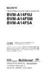
BVM-F24E/F24U/F24J/F24A
(AEP/UC/J/AUS)
4-087-014-05(1)
Sony Corporation
B & P Company
Printed in Japan
2004.08.13
 2001