1
B7FY-2001-01
内蔵 LTO3 ユニット 取扱説明書
Tape Drv LTO3 Ultrium3/Ultrium2 400GB User’s Guide
(PG-LT302)
J
E
はじめに
このたびは、弊社の内蔵 LTO3 ユニット(PG-LT302/PGBLT302/PGBLT302C)をお買い上
げいただき、誠にありがとうございます。
本書は、内蔵 LTO3 ユニット(以降、本製品)の取り扱いの基本的なことがらについて説
明しています。ご使用になる前に、本書をよくお読みになり、正しい取り扱いをされます
ようお願いいたします。
2007 年 4 月
安全にお使いいただくために
本書には、本製品を安全に正しくお使いいただくための重要な情報が記載されています。
本製品をお使いになる前に、本書を熟読してください。特に、本書の「安全上のご注意」をよくお読みにな
り、理解されたうえで本製品をお使いください。
また本書は、本製品の使用中にいつでもご覧になれるよう大切に保管してください。
本製品のハイセイフティ用途での使用について
本製品は、一般事務用、パーソナル用、家庭用、通常の産業用等の一般的用途を想定して設計・製造されて
いるものであり、原子力施設における核反応制御、航空機自動飛行制御、航空交通管制、大量輸送システム
における運行制御、生命維持のための医療器具、兵器システムにおけるミサイル発射制御など、極めて高度
な安全性が要求され、仮に当該安全性が確保されない場合、直接生命・身体に対する重大な危険性を伴う用
途(以下「ハイセイフティ用途」という)に使用されるよう設計・製造されたものではございません。お客
様は、当該ハイセイフティ用途に要する安全性を確保する措置を施すことなく、本製品を使用しないでくだ
さい。ハイセイフティ用途に使用される場合は、弊社の担当営業までご相談ください。
当社のドキュメントには「外国為替および外国貿易管理法」に基づく特定技術が含まれていることがありま
す。特定技術が含まれている場合は、当該ドキュメントを輸出または非居住者に提供するとき、同法に基づ
く許可が必要となります。
2
本書の表記
■ 警告表示
本書ではいろいろな絵表示を使っています。これは本製品を安全に正しくお使いいただ
き、あなたや他の人々に加えられるおそれのある危害や損害を未然に防止するための目印
となるものです。その表示と意味は次のようになっています。内容をよくご理解の上、お
読みください。
警告
この表示を無視して、誤った取り扱いをすると、人が死亡する可能性
または重傷を負う可能性があることを示しています。
注意
この表示を無視して、誤った取り扱いをすると、人が損害を負う可能
性があること、および物的損害のみが発生する可能性があることを示
しています。
また、危害や損害の内容がどのようなものかを示すために、上記の絵表示と同時に次の記
号を使用しています。
△で示した記号は、警告・注意を促す内容であることを告げるもので
す。記号の中やその脇には、具体的な警告内容が示されています。
で示した記号は、してはいけない行為(禁止行為)であることを告
げるものです。記号の中やその脇には、具体的な禁止内容が示されて
います。
●で示した記号は、必ず従っていただく内容であることを告げるもの
です。記号の中やその脇には、具体的な指示内容が示されています。
■ 本文中の記号
本文中に記載されている記号には、次のような意味があります。
記号
意味
お使いになる際の注意点や、してはいけないことを記述しています。
必ずお読みください。
ハードウェアやソフトウェアを正しく動作させるために必要なことが
書いてあります。必ずお読みください。
→
参照ページや参照マニュアルを示しています。
■ ドライブ名の表記について
CD-ROM ドライブのドライブ名を、
[CD-ROM ]で表記しています。
J
例:[CD-ROM]:\Setup.exe
3
■ 製品の呼び方
本文中の製品名称を次のように略して表記します。
製品名称
内蔵 LTO3 ユニット
(PG-LT302/PGBLT302/PGBLT302C)
®
本文中の表記
本製品、またはテープ装置
®
Microsoft Windows Server 2003, Standard Edition
Microsoft® Windows Server® 2003, Enterprise
Edition
Microsoft® Windows Server® 2003 R2, Standard
Edition
Windows Server 2003
Microsoft® Windows Server® 2003 R2, Enterprise
Edition
Microsoft® Windows Server® 2003, Standard x64
Edition
Microsoft® Windows Server® 2003, Enterprise x64
Edition
Microsoft® Windows Server® 2003 R2, Standard x64
Edition
Windows
Windows Server 2003 x64
Microsoft® Windows Server® 2003 R2, Enterprise
x64 Edition
Microsoft® Windows® 2000 Server
Red
Hat®
®
Enterprise Linux
ES (v.3 for x86)
Red Hat® Enterprise Linux® AS (v.3 for x86)
Red Hat® Enterprise Linux® ES (v.4 for x86)
Red Hat® Enterprise Linux® AS (v.4 for x86)
Red Hat® Enterprise Linux® ES (v.4 for EM64T)
Red Hat® Enterprise Linux® AS (v.4 for EM64T)
4
Windows 2000 Server
Linux v.3
Linux v.4
Linux
Linux v.4 for EM64T
SUSE™ Linux® Enterprise Server 9 for x86
SUSE Linux
BrightStor ARCserve Backup r11.5 for Windows
BrightStor ARCserve Backup
NetVault 7
NetVault
Windows 用バックアップユーティリティ
Windows Backup
安全上のご注意
本製品を安全にお使いいただくために、以降の記述内容を必ずお守りください。
■ 本製品の取り扱いについて
警告
・ 梱包に使用しているビニール袋はお子様が口に入れたり、かぶって遊んだりし
ないよう、ご注意ください。窒息の原因となります。
・ 異物(水・金属片・液体など)が本製品の内部に入った場合は、ただちにサー
バ本体の電源スイッチを切り、電源プラグをコンセントから取り外してくださ
い。
その後、修理相談窓口にご連絡ください。
そのまま使用すると、感電・火災の原因となります。特にお子様のいるご家庭
ではご注意ください。
・ 開口部(通風孔など)から内部に金属類や燃えやすいものなどの異物を差し込
んだり、落としたりしないでください。感電・火災の原因となります。
・ 本製品をお客様自身で改造しないでください。感電・火災の原因となります。
注意
・ 本製品を分解したり、解体したりしないでください。
・ 本製品は次の環境で動作させたり、保管したりしないでください。
- 極端な低温環境
- 極端な高温/多湿環境
- 温湿度変化の激しい環境
- 磁気の影響を受けやすい場所
- 衝撃や振動の加わる場所
- ゴミやほこり(煙草の煙、土埃、排気ガスなど)の多い環境
- 直射日光のあたる場所
- 発熱器具のそば
・ 寒い場所から暖かい場所に移動したり、室温を急に上げたりした直後は、内部
が結露する場合がありますので、使用しないでください。
結露したままお使いになると、本製品やデータカートリッジを損傷することが
あります。大きな温度変化があったときは、1 時間以上待ってから電源を入れ
てください。
・ サーバ本体の電源を切るときは、データカートリッジを取り出してください。
データカートリッジを本製品に挿入すると、磁気テープの記録面が露出します。
本状態が長く続くと、記録面へのほこりの付着やキズ発生の可能性があり、
データカートリッジが永久的に使用できなくなることがあります。
J
5
注意
・ ご使用しない場合は、本製品からデータカートリッジを取り出してください。
・ データカートリッジを入れたまま本製品を持ち運ばないでください。
・ データカートリッジの挿入時、無理に押し込まないでください。
・ 内部に液体や金属など異物が入った状態で使用しないでください。
何か異物が入った場合は、修理相談窓口にご相談ください。
・ 本製品前面の汚れは、柔らかい布でからぶきするか、布に水または中性洗剤を
含ませて、軽くふいてください。ベンジンやシンナーなど揮発性のものは避け
てください。
■ リサイクルについて
本製品を廃棄する場合、担当営業員に相談してください。本製品は産業廃棄物として処理
する必要があります。
梱包物の確認
お使いになる前に、次のものが梱包されていることをお確かめください。
万一足りないものがございましたら、担当営業員にご連絡ください。
( *1)
・ 内蔵 LTO3 ユニット(本製品)
(
*1)
・ 電源延長ケーブル
・ ネジ(4本)( *1)
・ クリーニングカートリッジ
・ ドライバフロッピーディスク「PRIMERGY LTO3 UNIT(PG-LT302) Device Driver for
Windows」
・ 保証書( *2)
・ 取扱説明書(本書)
・「テープ装置 媒体の定期交換とクリーニングで安心バックアップ!」(小冊子)
・「内蔵 LTO3 ユニット運用チェックシート(設置・運用確認編)」
*1:カスタムメイドサービス(PGBLT302/PGBLT302C)の場合、サーバ本体に組み込ま
れています。
*2:一般製品(PG-LT302)のみ添付。
Microsoft、Windows、Windows Server は、米国 Microsoft Corporation の米国およびその他の国におけ
る登録商標または商標です。
本取扱説明書に記載されている会社名、製品名は、各社の登録商標または商標です。
Linux は、Linus Torvalds 氏の米国およびその他の国における登録商標あるいは商標です。Red Hat お
よび Red Hat をベースとしたすべての商標とロゴは、米国およびその他の国における Red Hat, Inc. の
商標または登録商標です。
SUSE は、米国およびその他の国における Novell Inc. の商標です。
その他の各製品は、各社の著作物です。
All Rights Reserved, Copyright© FUJITSU LIMITED 2007
6
目次
1 サーバ本体への搭載と導入方法 . . . . . . . . . . . . . . . . . . . . . . . . .
8
1.1 設置環境の確認 . . . . . . . . . . . . . . . . . . . . . . . . . . . . . . . . . . . . . . . . . .
9
1.2 ジャンパの設定について . . . . . . . . . . . . . . . . . . . . . . . . . . . . . . . . . . .
10
1.3 サーバ本体への搭載・接続 . . . . . . . . . . . . . . . . . . . . . . . . . . . . . . . . .
11
1.4 デバイスドライバのインストール . . . . . . . . . . . . . . . . . . . . . . . . . . . .
12
1.5 Tape Maintenance Advisor について . . . . . . . . . . . . . . . . . . . . . . . . . .
16
1.6 バックアップジョブの設定(自動排出の設定) . . . . . . . . . . . . . . . . .
18
1.7 運用の確認 . . . . . . . . . . . . . . . . . . . . . . . . . . . . . . . . . . . . . . . . . . . . . .
19
1.8 デバイスドライバおよびバックアップソフトウェアの設定・注意事項
20
2 各部の名称と働き . . . . . . . . . . . . . . . . . . . . . . . . . . . . . . . . . . . .
23
2.1 フロントパネルおよびコネクタ . . . . . . . . . . . . . . . . . . . . . . . . . . . . .
23
2.2 データカートリッジの取り付け/取り外し . . . . . . . . . . . . . . . . . . . .
26
3 データカートリッジについて . . . . . . . . . . . . . . . . . . . . . . . . . . .
28
3.1 使用できるデータカートリッジ . . . . . . . . . . . . . . . . . . . . . . . . . . . . .
28
3.2 データカートリッジの取り扱い . . . . . . . . . . . . . . . . . . . . . . . . . . . . .
28
4 クリーニングについて . . . . . . . . . . . . . . . . . . . . . . . . . . . . . . . .
31
4.1 使用できるクリーニングカートリッジ . . . . . . . . . . . . . . . . . . . . . . . .
31
4.2 ヘッドクリーニングについて . . . . . . . . . . . . . . . . . . . . . . . . . . . . . . .
32
5 サプライ品 . . . . . . . . . . . . . . . . . . . . . . . . . . . . . . . . . . . . . . . . .
33
6 バックアップ運用上の注意 . . . . . . . . . . . . . . . . . . . . . . . . . . . . .
34
7 トラブルシューティング . . . . . . . . . . . . . . . . . . . . . . . . . . . . . . .
35
8 仕様 . . . . . . . . . . . . . . . . . . . . . . . . . . . . . . . . . . . . . . . . . . . . . .
39
付録 A 運用チェックシート(設置・運用確認編). . . . . . . . . . . . . . .
40
付録 B Tape Maintenance Advisor について . . . . . . . . . . . . . . . . .
43
B.1 はじめに . . . . . . . . . . . . . . . . . . . . . . . . . . . . . . . . . . . . . . . . . . . . . . . .
43
B.2 Tape Maintenance Advisor 導入のメリット . . . . . . . . . . . . . . . . . . . .
43
B.3 製品概要 . . . . . . . . . . . . . . . . . . . . . . . . . . . . . . . . . . . . . . . . . . . . . . . .
45
付録 C Windows 自動システム回復
(Automated System Recovery)について . . . . . . . . . . . .
47
C.1 Windows 自動システム回復ディスクについて . . . . . . . . . . . . . . . . . .
47
C.2 Windows 自動システム回復(ASR)の使用方法 . . . . . . . . . . . . . . . .
49
J
7
1
サーバ本体への搭載と導入方法
この章では、本製品のサーバ本体への搭載と導入方法について説明しています。
本製品のサーバ本体への搭載と導入方法は、次の手順で行います。
カスタムメイドサービスの場合、手順 2 ~ 4 は必要ありません。
1 設置環境の確認
→「1.1 設置環境の確認」
(P.9)
2 ジャンパの設定
→「1.2 ジャンパの設定について」(P.10)
3 サーバ本体への搭載・接続
→「1.3 サーバ本体への搭載・接続」(P.11)
4 デバイスドライバのインストール
→「1.4 デバイスドライバのインストール」(P.12)
5 Tape Maintenance Advisor のインストール
→「1.5 Tape Maintenance Advisor について」(P.16)
6 バックアップジョブの設定(自動排出の設定)
→「1.6 バックアップジョブの設定(自動排出の設定)」
(P.18)
7 運用の確認
→「1.7 運用の確認」(P.19)
8 デバイスドライバおよびバックアップソフトウェアの設定・注意事項
→「1.8 デバイスドライバおよびバックアップソフトウェアの設定・注意事項」
(P.20)
8
1.1
設置環境の確認
サーバの設置環境については、サーバ本体に添付の『安全上のご注意』および『はじめに
お読みください』を参照してください。
本製品は、データ記録面が内部で露出するため、設置環境(特に塵埃)の影響を受けやす
くなっています。一般的に、床面に近いほど塵埃濃度は高くなるので、机上など床面より
離れた場所への設置をお勧めします。次の「避けて頂きたい設置例」を参考に、よりほこ
りの少ない環境に設置するよう配慮をお願いいたします。
■ 避けていただきたい設置例
・ 本製品を床に直置き
・ 人通りの多い場所
・ 開放されるドアや窓の近く。特に土埃や車の排気ガス、などの外部の影響を受ける場所
・ 空気の取り込み口、吹き出し口の近く。(空調、エアコン、換気扇、などに注意)
・ タバコの煙の影響を受ける場所(本製品が設置された部屋での喫煙禁止)
・ プリンタの近くでトナーの影響を受ける場所
・ コピー機、シュレッダー、FAX、など、紙を扱う装置の近くで、紙の粉の影響を受ける
場所
・ 設置後、数か月でデータカートリッジ投入口や周囲に塵埃が堆積するような場所
「 安全上のご注意」(→ P.5)も併せて参照してください。
J
1 サーバ本体への搭載と導入方法 9
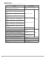
1.2
ジャンパの設定について
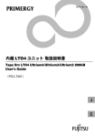
サーバ本体に本製品を搭載する場合、SCSI-ID 番号の設定が必要です。
SCSI-ID 番号は、本製品背面(下図)のショートジャンパで設定できます。
サーバ本体に添付の「PRIMERGY ドキュメント&ツール CD」内の『ユーザーズガイド』
の「内蔵オプションの取り付け」の章に従って、SCSI-ID 番号を設定してください。
[本製品背面]
0
1
2
3
SCSI ID 変更禁止
`
`
SCSI-ID 以外の設定は変更しないでください。
ジャンパを横向きに取り付けないでください。
次の表のように設定できます。
SCSI-ID 番号
ショートジャンパ
0
1
2
3
0
オープン
オープン
オープン
オープン
1
ショート
オープン
オープン
オープン
2
オープン
ショート
オープン
オープン
3
ショート
ショート
オープン
オープン
4
オープン
オープン
ショート
オープン
5(*)
6
ショート
オープン
ショート
オープン
オープン
ショート
ショート
オープン
7
ショート
ショート
ショート
ショート
8
オープン
オープン
オープン
ショート
9
ショート
オープン
オープン
ショート
10
オープン
ショート
オープン
ショート
11
ショート
ショート
オープン
ショート
12
オープン
オープン
ショート
ショート
13
ショート
オープン
ショート
ショート
14
オープン
ショート
ショート
ショート
15
ショート
ショート
ショート
ショート
*):ご購入時の設定
10
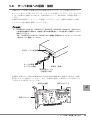
1.3
サーバ本体への搭載・接続
本製品のサーバ本体への搭載方法および接続方法については、サーバ本体に添付の「ド
キュメント&ツール CD」内の『ユーザーズガイド』を参照してください。『ユーザーズガ
イド』に本製品の記載がない場合は、内蔵 LTO2 ユニット(PG-LT201)の記載を参照して
ください。
本製品は LVD SCSI インタフェースに接続してください。また、本製品を接続した SCSI
ケーブル上に他の装置を接続しないでください。
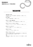
`
PRIMERGY TX200 S3、TX200FT S3、RX600 S2、RX600 S3、RX600 S3(SAS モデル)
に本製品を搭載する場合は、本製品に添付の電源延長ケーブルを使用して電源ケーブルに
接続してください。
なお、PRIMERGY TX200 S3 / TX200FT S3 に搭載する場合は 5 インチストレージベイの
一番上のベイに搭載してください。
SCSIࠤࡉ࡞ࠍធ⛯
ࠨࡃߩ㔚Ḯ
ࠤࡉ࡞ߦធ⛯
ᧄຠ㧔⢛㕙㧕
㔚Ḯᑧ㐳ࠤࡉ࡞
㧔ᧄຠߦᷝઃ㧕
本製品を SCSI カード PG-128/PGB128 または PG-1281/PGB1281 に接続する場合は、LVD/
SE 用のコネクタを使用してください。また、本製品を接続した SCSI カードの外付デバイ
ス用コネクタを使用しないでください。
ᧄຠߦធ⛯
↪ߒߥߎߣ
J
↪ߒߥߎߣ
1 サーバ本体への搭載と導入方法 11
1.4
デバイスドライバのインストール
Windows で本製品を使用する場合、本製品に添付のドライバフロッピーを使用し、次の手
順でデバイスドライバをインストールしてください。なお、Linux の場合はデバイスドラ
イバをインストールする必要はありません。
1.4.1
デバイスドライバのインストール(PRIMERGY FT モ
デル以外に搭載の場合)
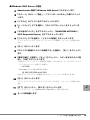
■ Windows Server 2003 / Windows Server 2003 x64 の場合
1 Administrator 権限で Windows にログオンします。
2 「スタート」ボタン→「コントロールパネル」→「システム」の順にク
リックします。
3 「ハードウェア」タブを選択し、[デバイスマネージャ]をクリックしま
す。
4 「その他のデバイス」をダブルクリックし、「QUANTUM ULTRIUM 3
SCSI Sequential Device」をダブルクリックします。
5 「ドライバ」タブを選択し、[ドライバの更新]をクリックします。
「ハードウェアの更新ウィザードの開始」というメッセージが表示されます。
6 「ソフトウェア検索のため、Windows Update に接続しますか?」と表
示されるので、「いいえ、今回は接続しません」をクリックし、[次へ]を
クリックします。
7 「一覧または特定の場所からインストールする」をクリックし、[次へ]を
クリックします。
8 「次の場所で最適のドライバを検索する」をクリックします。
9 「次の場所を含める」にチェックを入れ、[参照]ボタンを押してコピー元
にデバイスドライバを復元したフォルダを指定します。
・ 添付のドライバフロッピーを使用する場合(またはダウンロードしたデバイスド
ライバをフロッピーに復元した場合)
A:\LTO3HH
・ ServerStart などの CD を使用する場合
[CD-ROM]:\DRIVERS\tape\LTO3HH
10 [次へ]をクリックします。
「ハードウェアの更新ウィザードの完了」とメッセージが表示されます。
11 [完了]をクリックし、[閉じる]をクリックします。
「テープドライブ」に「Quantum LTO 3 Tape Drive」と表示されます。
12 サーバを再起動します。
12
■ Windows 2000 Server の場合
1 Administrator 権限で Windows 2000 Server にログオンします。
2 「スタート」ボタン→「設定」→「コントロールパネル」の順にクリック
します。
3 「システム」のアイコンをダブルクリックします。
4 「ハードウェア」タブを選択し、[デバイスマネージャ]をクリックしま
す。
5 「その他のデバイス」をダブルクリックし、「QUANTUM ULTRIUM 3
SCSI Sequential Device」をダブルクリックします。
6 「ドライバ」タブを選択し、[ドライバの更新]をクリックします。
「デバイスドライバのアップグレードウィザードの開始」とメッセージが表示され
ます。
7 [次へ]をクリックします。
8 「デバイスに最適なドライバを検索する」を選択し、[次へ]をクリックし
ます。
9 「場所を指定」を選択し、[次へ]をクリックし、コピー元を次のように設
定し、[OK]をクリックします。
・ 添付のドライバフロッピーを使用する場合(またはダウンロードしたデバイスド
ライバをフロッピーに復元した場合)
A:\LTO3HH
・ ServerStart などの CD を使用する場合
[CD-ROM]:\DRIVERS\tape\LTO3HH
「次のデバイスのドライバが検索されました」とメッセージが表示されます。
10 [次へ]をクリックします。
「デバイスドライバのアップグレードウィザードの完了」とメッセージが表示され
ます。
11 [完了]をクリックし、[閉じる]をクリックします。
「テープドライブ」に「Quantum LTO 3 Tape Drive」と表示されます。
J
12 サーバを再起動します。
1 サーバ本体への搭載と導入方法 13
1.4.2
デバイスドライバのインストール(PRIMERGY FT モ
デルに搭載の場合)
■ 注意事項
・ 本製品は、FT1 にのみ搭載可能です。FT2 には搭載できません。
・ 本製品を同時に 2 つ搭載できません。
・ 本製品は FTvirtual Server(業務用 OS)からのみ使用可能です。CoServer(入出力 OS)
からは本製品を使用できません。
・ FT モデルでは、自動システム回復(ASR)セット、システム復旧ディスクを使用した
システムの復旧はできません。復旧には、サーバに添付のリカバリ CD を使用してくだ
さい。
・ 内蔵 5 インチオプションの取り付けについては、必ず FT モデルの『ユーザーズガイド』
を参照して作業をしてください。
■ Windows Server 2003 の場合
1 本製品を FT1 に搭載します。
2 FT1、FT2 の電源を入れ、CoServer を Online モードで起動します。
3 Administrator 権限で CoServer1 にログオンします。
サーバ本体が TX200FT S3 の場合、次の手順で一 度再起動してください。
1. 「スタート」ボタン→「すべてのプログラム」→「Marathon Endurance」→
「Management Tasks」→「Endurance Configuration」→「Restart」の順にク
リックします。
確認のメッセージが表示されます。
2. [OK]をクリックします。
再起動後は、手順 2 から行ってください。
再起動後は、上記手順を行う必要はありません。
4 「スタート」ボタン→「コントロールパネル」→「システム」の順にク
リックします。
5 「ハードウェア」タブを選択し、[デバイスマネージャ]をクリックしま
す。
デバイスマネージャが起動します。
6 「その他のデバイス」をダブルクリックし、「QUANTUM ULTRIUM 3
SCSI Sequential Device」をダブルクリックします。
7 「ドライバ」タブを選択し、[ドライバの更新]をクリックします。
セットアップウィザードが表示されます。
8 「ソフトウェア検索のため、Windows Update に接続しますか?」と表
示されるので、「いいえ、今回は接続しません」をクリックし、[次へ]を
クリックします。
ウィザードに従ってインストールを行ってください。
14
9 インストール方法で「一覧または特定の場所からインストールする」をク
リックし、[次へ]をクリックします。
10 検索とインストールのオプションで、「次の場所で最適のドライバを検索
する」を選択して、次のオプションを設定します。
・「リムーバブルメディア(フロッピー、CD-ROM など)を検索」のチェックを外
します。
・「次の場所を含める」にチェックを入れ、デバイスドライバを復元したフォルダ
を指定します。
・ A ドライブのフロッピーに復元した場合
A:\LTO3HH
・ C ドライブの Temp フォルダに復元した場合
C:\Temp\LTO3HH
11 [次へ]をクリックします。
「ハードウェアの更新ウィザードの完了」とメッセージが表示されます。
12 [完了]をクリックして、終了します。
「テープドライブ」配下に「Quantum LTO 3 Tape Drive」と表示されます。
13 FT モデルの『ユーザーズガイド』の「内蔵バックアップ装置取り付け後
の操作」の章に従い、FTvirtual Server へのリダイレクト作業を実施し
ます。
FTvirtual Server へのリダイレクト作業が完了すると、FTvirtual Server 上の「デバイ
スマネージャ」にその他のデバイスとして「QUANTUM ULTRIUM 3 SCSI
Sequential Device」が表示されます。
14 FTvirtual Server で手順 4 ~ 12 を繰り返してドライバをインストール
後、FTvirtual Server を再起動します。
J
1 サーバ本体への搭載と導入方法 15
1.5
Tape Maintenance Advisor について
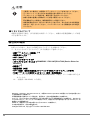
サーバ本体に「Tape Maintenance Advisor」をインストールすることにより、3 か月ごとの
磁気ヘッドのクリーニングの時期を通知することができます。定期的な磁気ヘッドのク
リーニングを行うために、「Tape Maintenance Advisor」を使用されることをお勧めします。
「Tape Maintenance Advisor」については、
「付録 B Tape Maintenance Advisor について」(→
P.43)を参照してください。
1.5.1
インストールモジュールの準備
「Tape Maintenance Advisor」は、Windows 用と Linux 用でモジュールが異なります。使用す
る OS に応じたインストールモジュールを準備してください。
■ Windows Server 2003 / Windows Server 2003 x64 / Windows 2000
Server の場合
・ Tape Maintenance Advisor for Windows
サーバ本体に添付の ServerStart CD-ROM に格納されています。
- モジュール
[CD-ROM]:\PROGRAMS\Japanese\TmAdvisor
- 操作説明書(Fujitsu Tape Maintenance Advisor for Windows 操作説明書)
[CD-ROM]:\PROGRAMS\Japanese\TmAdvisor\TMAdoc
` 「Tape Maintenance Advisor」は、弊社のインターネット情報ページ
(http://primeserver.fujitsu.com/primergy/)内に最新版が登録されています。
『ダウンロー
ド』→『ダウンロード検索』で、サーバの製品名および型名を選択し、カテゴリに「添付
ソフト」を指定して検索してください。
■ Linux v.3 / Linux v.4 / Linux v.4 for EM64T の場合
・ Tape Maintenance Advisor for Linux
「Tape Maintenance Advisor for Linux」は、弊社のインターネット情報ページ
(http://primeserver.fujitsu.com/primergy/)内の『ダウンロード』→『ダウンロード検索』
で、サーバの製品名および型名を選択し、カテゴリに「添付ソフト」を指定して検索
し、ダウンロードしてください。
(例:Fujitsu Tape Maintenance Advisor for Linux V3.0)
本ソフトウェアをダウンロードしたときは、tar.gz 形式になっています。次のコマンド
を実行すると復元できますので、あらかじめ適当なフォルダに復元してください(復
元作業は Linux で行ってください。Windows での復元は避けてください)。
tar xvfz ファイル名.tar.gz
復元すると次のようなフォルダ構成になっています。モジュールは、使用する Linux
のバージョンによって異なります。
- モジュール
・ Linux v.3 の場合
TmAdvisor/forv3/TmAdvisor/TMA
16
・ Linux v.4 / Linux v.4 for EM64T の場合
TmAdvisor/forv4/TmAdvisor/TMA
- 操作説明書(Fujitsu Tape Maintenance Advisor for Linux 操作説明書)
TmAdvisor/TMAdoc
1.5.2
インストール方法
インストール方法は、各操作説明書を参照して行ってください。ここでは、インストール
する実行ファイルについて説明します。
■ Tape Maintenance Advisor for Windows
Administrator 権限で、サーバ本体に添付の ServerStart CD-ROM に格納されている次のファ
イルを実行してください。
[CD-ROM]:\PROGRAMS\Japanese\TmAdvisor\Setup.exe
ダウンロードした場合は、readme.txt の内容に従ってインストールしてください。
■ Tape Maintenance Advisor for Linux
使用する Linux のバージョンに応じて、管理者権限で、次のファイルを実行してください。
・ Linux v.3 の場合
TmAdvisor/forv3/TmAdvisor/TMA/Installer.bat
・Linux v.4 / Linux v.4 for EM64T の場合
TmAdvisor/forv4/TmAdvisor/TMA/Installer.bat
1.5.3
設定方法
クリーニング時期や通知方法の設定を行います。設定方法の詳細は、各操作説明書を参照
して設定ください。
`
1.5.4
初期設定では、ポップアップメッセージを毎週月曜日の午前 9 時に表示し、イベントログ
通知を行うようになっています。
使用方法(概要)
・ 一般オペレータ(または管理者)は、メッセージを受け取ったら、テープ装置のクリー
ニング作業を行い、「Tape Maintenance Advisor」に作業を行った旨を伝えます。
・ 管理者は、イベントログなどを監視し、クリーニング作業を忘れていないかチェックし
てください。
使用方法の詳細は、各操作説明書を参照してください。
J
1 サーバ本体への搭載と導入方法 17
1.6
バックアップジョブの設定(自動排出の設定)
バックアップを自動で行う場合は、次の手順に従ってバックアップ後にデータカートリッ
ジを自動的に排出するように設定してください(手動でバックアップを行う場合もバック
アップ後は、必ずデータカートリッジを取り出してください)
。
■ BrightStor ARCserve Backup の場合
1 バックアップジョブのオプションのバックアップマネージャで[オプショ
ン]ボタンをクリックします。
2 「操作」タブの[バックアップ終了後のメディアのイジェクト]を「メ
ディアをイジェクトする」に設定します。
■ Windows Backup の場合
バッチファイルなどで、バックアップのコマンドの後に次のコマンドを実行する記述を
追加します。
例:rsm refresh /lf"Quantum LTO 3 Tape Drive"(*1)
rsm eject /lf"Quantum LTO 3 Tape Drive"/astart
*1:指定する名前は、「コンピュータの管理」の「記憶域→リムーバブル記憶域」の
「ライブラリ」(Windows Server 2003 / Windows Server 2003 x64 の場合)または
「物理的な場所」(Windows 2000 Server の場合)で確認してください。
[バッチファイルの例](Windows Server 2003 の場合)
ⴕ⇟ภ
䊋䉾䉼䊐䉜䉟䊦䈱ౝኈ
1:
2:
3:
@echo off
cls
setlocal
4:
5:
6:
7:
8:
9:
10:
11:
12:
13:
rsm inventory /lf"Quantum LTO 3 Tape Drive" /aFULL
timeout /t 60
rsm refresh /lf"Quantum LTO 3 Tape Drive"
timeout /t 60
for /f "Tokens=1-4 Delims=/ " %%i in ('date /t') do set dt=%%i-%%j-%%k-%%l
for /f "Tokens=1" %%i in ('time /t') do set tm=-%%i
set tm=%tm::=-%
set dtt=%dt%%tm%
ntbackup backup @c:\test\test.bks /n "%computername%-%dtt%" /d "daily
%dtt%" /j "daily %dtt%" /p "LTO Ultrium" V:no /R:no /L:f /M normal /RS:NO
/HC:ON /UM
timeout /t 60
14:
15:
16:
17:
rsm refresh /lf"Quantum LTO 3 Tape Drive"
timeout /t 60
rsm eject /lf"Quantum LTO 3 Tape Drive"
timeout /t 60
18:
endlocal
䊋䉾䉪䉝䉾䊒
䋨㪁㪉䋩
䊂䊷䉺
䉦䊷䊃䊥䉾䉳
䈱ឃ
* 2:\test\test.bks は、Windows Backup を起動し、「バックアップ」タブでバック
アップする対象にチェックを入れ、
「ジョブ」メニューから「選択したジョブの
保存」を選んで作成してください。
Windows Backup のバッチファイルでの使用例は、マイクロソフト技術情報 239892
(http://support.microsoft.com/default.aspx?scid=kb;ja;239892)などを参照してください。
ntbackup, rsm コマンドの使用法は、Windows のヘルプを参照してください(「スタート」
ボタン→「ヘルプとサポート」の順にクリックし、
「ntbackup」または「rsm」を検索し
てください)。
18
■ Linux のコマンドで使用する場合
シェルスクリプトなどで、バックアップコマンドの後に次のコマンドを実行する記述を
追加してください(/dev/st0 は、環境に合わせて変更してください)
。
mt -f /dev/st0 eject
■ NetVault の場合
NetVault のデバイス管理で、デバイス名を確認します。
ここでは、本製品を「NetVaultSV:_1-0.3.0_(QUANTUM_ULTRIUM_3)」として説明しま
す。
確認したデバイス名を使用し、NetVault をインストールしたディレクトリ(/usr/
netvault)の scripts/users ディレクトリに、次の内容のシェルスクリプト(ここでは、
tapeeject.sh とします)を作成します(/usr/netvault/scripts/users/tapeeject.sh を作成しま
す)
。
[tapeeject.sh の例]
/usr/netvault/util/nvdeviceeject -servername NetVaultSV
-devicename "NetVaultSV:_1-0.3.0_(QUANTUM_ULTRIUM_3)"
-servername:対象となるサーバ本体の名前を指定します(例 :NetVaultSV)
-devicename:対象となるドライブ(本製品)の名前を指定します
(例 : NetVaultSV:_1-0.3.0_(QUANTUM_ULTRIUM_3))
バックアップ実行時に、NetVault のバックアップウィンドウで、詳細設定(Advanced
Option)タブのポスト・スクリプト(Use Post Script)にチェックを入れ、
「users/
tapeeject.sh」を指定してください。
1.7
運用の確認
日々のバックアップ運用上の注意事項を、
「付録 A 運用チェックシート (設置・運用確認
編)」
(→ P.40)にまとめてあります。チェックシートを使用して、運用の確認を行ってく
ださい。また、テープ装置全般の注意事項について、本製品に添付の小冊子「テープ装
置、媒体の定期交換とクリーニングで安心バックアップ!」(*) にまとめてありますので、
併せてご確認ください。
*:インターネット情報ページ(http://primeserver.fujitsu.com/primergy/)内の「技術情報」
のシステム構築の手引きに最新版を掲載しています。
J
1 サーバ本体への搭載と導入方法 19
1.8
デバイスドライバおよびバックアップソフト
ウェアの設定・注意事項
本章の情報は、2007 年 2 月現在のものです。内容が変わることがありますがご了承くださ
い。
■ Windows 用デバイスドライバについて
本製品の Windows 用のデバイスドライバの最新版は、インターネット情報ページ
(http://primeserver.fujitsu.com/primergy/)内の『ダウンロード』→『ダウンロード検索』で
サーバの製品名および型名を選択し、カテゴリに「バックアップ装置」を指定して検索
し、ダウンロードしてください。デバイスドライバは、最新版をご使用されることをお勧
めします。
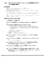
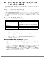
■ バックアップソフトウェアについて
本製品は、次のバックアップソフトウェアで使用できます。
OS
Windows Server 2003
Windows Server 2003 x64
Windows 2000 Server
バックアップソフトウェア
BrightStor ARCserve Backup r11.5 + SP2(QO81201)
以降 (*)、Windows Backup
BrightStor ARCserve Backup r11.5 + SP2(QO81201)
以降(*)
(SP4 以降)
Linux AS v.3
NetVault7 7.4.2(*)
Linux AS v.4
NetVault7 7.4.2(*)
Linux AS v.4 for EM64T
NetVault7 for EM64T 7.4.2(*)
*:BrightStor ARCserve Backup および NetVault については、次の弊社ソフトウェアガ
イドをご参照ください。
・ BrightStor ARCserve Backup
Windows ソフトウェアガイド(http://software.fujitsu.com/jp/guide/windows/)で
「ARCserve」を検索してください
・ NetVault
Linux ソフトウェアガイド(http://software.fujitsu.com/jp/guide/linux/)で
「NetVault」を検索してください
■ BrightStor ARCserve Backup の設定について
・ BrightStor ARCserve Backup を使用する場合は、デバイスドライバのインストール後に
BrightStor ARCserve Backup の「デバイス環境設定」で「デバイスの有効/無効(RSM
対応)」オプションを選択し、リムーバブル記憶域の管理を無効(チェックを付ける)
にしてください。
・ バックアップジョブの設定時に、本製品が割り当てられているデバイスグループ名を控
えておいてください。修理などで本製品を交換したあとの再設定時に必要です。
・ BrightStor ARCserve Backup をアンインストールする際は、事前に「デバイス環境設定」
-「デバイスの有効/無効(RSM 対応)」オプションを選択し、リムーバブル記憶域の
管理を有効(チェックを外す)にしてください。
20
■ 修理などで本製品を交換したあとの BrightStor ARCserve Backup の
再設定について
BrightStor ARCserve Backup は、修理などで本製品が交換された場合、デバイスグループが
新規に作成される場合があります。本製品の交換後は、次の項目を確認してください。
確認項目
デバイスの有効/無効
(RSM 対応)
デバイスグループ
Disaster Recovery Option
を使用している場合
確認内容
リムーバブル記憶域の管理が無効(チェックが付いてい
る)か確認してください。
交換前のデバイスグループ名(ジョブの設定時のデバイス
グループ名)と同じデバイスグループ名に設定してくださ
い。
交換前のデバイスグループ名が分からない場合は、ジョブ
の再設定を行ってください。
交換後、復旧用フロッピーディスクを再作成してくださ
い。
■ ASR(Automated System Recovery)に関する注意事項
Windows Server 2003 / Windows Server 2003 x64 には、Windows 自動システム回復機能
(Automated System Recovery、以下 ASR)があります。
この機能には、次の注意事項があります。
・ ASR ディスクへのデバイスドライバの追加について
本製品を ASR で使用する場合、ASR ディスクに本製品のデバイスドライバを追加する
必要があります。作成方法については、
「付録 C Windows 自動システム回復(Automated
System Recovery)について」
(→ P.47)を参照してください。
■ Windows 自動システム回復(ASR)使用時および
BrightStorARCserve Backup の Disaster Recovery Option 使用時
に、フロッピーディスクドライブ(USB)を使用する場合について
・ サーバ起動時のフロッピーディスクドライブ認識に関する注意事項
サーバ起動時にフロッピーディスクが挿入されたフロッピーディスクドライブ(USB)
が接続されていない場合は、BIOS がフロッピーディスクドライブ(USB)を認識でき
ません。Windows / Linux などのオペレーティングシステムインストール時、Windows の
自動システム回復(ASR)使用時および BrightStor ARCserve Backup の Disaster Recovery
Option 使用時は、必ずフロッピーディスクが挿入されたフロッピーディスクドライブ
(USB)を接続してからサーバを起動してください。
・ フロッピーディスク媒体交換認識に関する注意事項
次のソフトウェアにより、Windows のバックアップデータを使ってシステムリカバリを
使用する際、および Windows の手動インストールの際に、フロッピーディスクの媒体
交換を認識できないため、デバイスドライバなどを正しく読み込めず、システムリカバ
リ/インストールが正常に行えないことがあります。
- BrightStor ARCserve Backup r11.x for Windows Disaster Recovery Option. Japanese
J
- Windows Server 2003 自動システム回復機能
画面の手順に従い【Enter】キーを押してもフロッピーディスクドライブ(USB)のフ
ロッピーディスクアクセスランプが点灯せず、フロッピーディスクにアクセスできない
場合は、次の操作を行ってください。
1 サーバ本体への搭載と導入方法 21
1. フロッピーディスクを取り出し、2 秒以上待ってから【Enter】キーを数回押しま
す。
2. フロッピーディスクを取り出し、2 秒以上待ってから【Enter】キーを押します。
フロッピーディスクにアクセスできない場合は、再度上記手順を行ってください。
22
2
各部の名称と働き
この章では、本製品の各部の名称と働きについて説明しています。
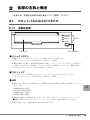
2.1
フロントパネルおよびコネクタ
2.1.1
本製品前面
POWER
ACTIVITY
ERROR
LED
CLEAN
EJECT
䊐䊨䊮䊃䊄䉝
䉟䉳䉢䉪䊃䊗䉺䊮
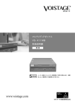
■ イジェクトボタン
本製品に入っているデータカートリッジを取り出すときに押します。
→「2.2 データカートリッジの取り付け/取り外し」
(P.26)
本製品が動作中の場合(ACTIVITY LED が点滅し、ロード/アンロードやデータの書き込
み/読み込みを行っている場合)、イジェクトボタンを押さないでください。動作が終わ
るまで待ってからイジェクトボタンを押してください。
■ フロントドア
データカートリッジを挿入するときは、フロントドアを上に引き上げてください。
→「2.2 データカートリッジの取り付け/取り外し」
(P.26)
■ LED
本製品には、次の 4 つの LED があり、電源投入時の自己診断、使用中の状態やエラーな
どを示します。
・ POWER LED(緑色)
・ ACTIVITY LED(緑色)
・ ERROR LED (赤色)
・ CLEAN LED(橙色)
各 LED の状態の主な意味は次のとおりです。詳しくは、「7 トラブルシューティング」の
「■ LED の表示によるトラブルシューティング」(→ P.35)の表を参照してください。
J
点滅は 1 秒に 1 回、高速点滅は 1 秒に 4 回点滅します。
2 各部の名称と働き 23
以下の表での記号は、次の状態を意味します。
●:消灯、○:点灯、◎:点滅(1 秒に 1 回)、☆:高速点滅(1 秒に 4 回)
・ POWER LED の表示について
POWER LED の表示
状態
● POWER : 消灯
本製品に電源が入っていません。
○ POWER : 点灯
本製品に電源が入っています。
・ ACTIVITY LED/ERROR LED/CLEAN LED の表示について
LED の表示
POWER
:点灯
状態
本製品に電源が入っており使用可能な状態です。
ACTIVITY :消灯
ERROR
CLEAN
:消灯
:消灯
:点灯
ACTIVITY :点滅
:点滅または消灯
ERROR
:点滅
CLEAN
電源投入時の自己診断テストおよび初期化動作を実行していま
す。
:点灯
ACTIVITY :点滅
:消灯
ERROR
:消灯
CLEAN
本製品が動作中です(データカートリッジのロード・アンロー
ド、巻き戻し、データの書き込み、データの読み出しなどを
行っています)。
POWER
POWER
POWER
:点灯
ACTIVITY :消灯
ERROR
CLEAN
:消灯
:点灯
クリーニングが必要です。
CLEAN LED が点灯するのは次の場合です。
・ 本製品自身がクリーニングを必要と判断した場合
・ データカートリッジの動作時間が 100 時間を越えた場
合。
クリーニングカートリッジを使用してクリーニングを行ってく
ださい。→「4 クリーニングについて」(P.31)
:点灯
ACTIVITY :点灯
:消灯
ERROR
:点灯
CLEAN
POWER
POWER
:点灯
ACTIVITY :点灯
CLEAN
:消灯
:高速点滅
POWER
:点灯
ERROR
ACTIVITY :消灯
CLEAN
:高速点滅
:高速点滅
POWER
:点灯
ERROR
ACTIVITY :消灯
ERROR
CLEAN
24
:高速点滅
:消灯
クリーニング動作中です。
クリーニングカートリッジが寿命(50 回以上使用)です。新し
いクリーニングカートリッジを使用してください。
→「4 クリーニングについて」(P.31)
クリーニングに失敗した、またはデータカートリッジでメディ
アエラーが発生しました。データカートリッジが挿入されてい
ない場合は、前回使用したデータカートリッジでメディアエ
ラーが発生しています。→「7 トラブルシューティング」(P.35)
回復不可能なエラーが発生しました。
→「7 トラブルシューティング」(P.35)
`
2.1.2
CLEAN LED が点灯すると、正しくクリーニングが完了するまで消灯しません(電源をオ
ン/オフしても消灯しません)。CLEAN LED が点灯した場合は、クリーニングカート
リッジを使用してクリーニングを行ってください。
本装置背面
ࠫࡖࡦࡄ
SCSIࠦࡀࠢ࠲
㔚Ḯࠦࡀࠢ࠲
■ ジャンパ
SCSI-ID 番号を設定します。
→「1.2 ジャンパの設定について」(P.10)
■ SCSI コネクタ
本製品用の SCSI ケーブルを接続してください。
→「1.3 サーバ本体への搭載・接続」(P.11)
■ 電源コネクタ
サーバ本体の内蔵オプション用の電源ケーブルを接続してください。
→「1.3 サーバ本体への搭載・接続」(P.11)
J
2 各部の名称と働き 25
2.2
データカートリッジの取り付け/取り外し
データカートリッジは、
「3 データカートリッジについて」(→ P.28)を参照して正しく取
り扱ってください。
■ セット方法
データカートリッジは矢印が付いている面を上に向け、ラベル貼り付け面が手前になるよ
うにし、本製品のフロントドアを上に押し上げ、ゆっくりと挿入してください。止まるま
で挿入すると、自動的にロードが開始されます。
`
本製品およびデータカートリッジの損傷を避けるため、次のことに注意してくださ
い。
・力を加えすぎないでください。
・データカートリッジを正しい方向、正しい位置にまっすぐ挿入してください。
[本製品]
挿入方向を示す矢印
ラベル貼り付け面
[データカートリッジ]
`
26
データカートリッジをセットした直後にバックアップまたはリストアなどの操作を行う場
合、データカートリッジのロードが完了してから(ACTIVITY LED の点滅が終わり消灯し
てから)行ってください。
■ 取り出し方法
ACTIVITY LED が消灯していることを確認し、イジェクトボタンを押します。
取り出したデータカートリッジは、ケースに入れて保管してください。
`
`
`
`
データカートリッジが出てくるときに指で押さえたり、押し込んだりしないでくだ
さい。またデータカートリッジが完全にイジェクトされる前にデータカートリッジ
を引き抜いたりしないでください。本製品が故障する原因となります。
取り出しは、本製品がデータカートリッジを動かしていないとき(ACTIVITY LED が消え
ている状態)に行ってください。
バックアップソフトウェアによっては、イジェクトボタンによるデータカートリッジの取
り出しをできないようにしていることがあります(NetVault など)。この場合、イジェク
トボタンを押してもデータカートリッジが排出されません。バックアップソフトウェアか
らの操作でデータカートリッジを取り出してください。
本製品の電源が入っていない状態で、データカートリッジのセット/取り出しはできませ
ん。
J
2 各部の名称と働き 27
3
データカートリッジについて
この章では、本製品で使用できるデータカートリッジについて説明しています。
3.1
使用できるデータカートリッジ
本製品には、次の富士通純正品を使用されることをお勧めします。サプライ品について
は、
「5 サプライ品」(→ P.33)を参照してください。
商品番号
記憶容量(*)
出荷単位
Ultrium2 データカートリッジ
0160310
200GB
5巻
Ultrium3 データカートリッジ
0160320
400GB
5巻
品名
*:データ圧縮機能を使わない場合の値。記憶容量は、1GB=1000 × 1000 × 1000byte 換算です(な
お、本製品では Ultrium1 データカートリッジは読み込みのみ可能です)。
データカートリッジの消耗によるバックアップ失敗を防止するため、次のどちらか早い方
を目安にデータカートリッジを交換してください。
データカートリッジの交換周期(どちらか早いほう)
・ 使用期間で1年
・ 使用回数で 1000 回
データカートリッジの寿命は、本製品の設置環境(温度、湿度、塵埃など)や動作状況に
より大きく変化します。
`
3.2
データカートリッジは消耗品です。消耗したデータカートリッジは、磁気テープ表
面の損傷、磁気ヘッド汚れの増加、メディアエラー多発など不具合の原因となりま
す。
データカートリッジの取り扱い
本製品で使用するデータカートリッジの取り扱い方法および注意事項について説明しま
す。
データカートリッジを取り扱うときは、次の事項をお守りください。
・ データカートリッジは、清潔に保ってください。
・ データカートリッジは、使用前に以下の確認を行ってください。
- データカートリッジの割れや破損のないこと
- ラベルが貼られている場合、正しい位置に貼られていること
→「3.2.1 データカートリッジラベルのセット」(P.29)
- リーダーピンが正しく固定されていること
→「3.2.4 データカートリッジのリーダーピンの状態確認」
(P.30)
・ 壊れたデータカートリッジを、本製品に絶対に入れないでください。
・ データカートリッジを開いて磁気テープ部分を取り出したりしないでください。
・ 磁気テープ部分を直接手で触らないでください。
28
・ データカートリッジを、直射日光の当たる場所や湿気のある場所に放置しないでくださ
い。
・ データカートリッジを磁界のある場所(ディスプレイやスピーカーの近くなど)に放置
しないでください。
・ 落下などにより強い衝撃が加わったデータカートリッジは、使わないでください。
3.2.1
データカートリッジラベルのセット
データカートリッジには、データカートリッジに貼り付けるためのラベルが添付されてい
ます。ラベルは、次の図に示す位置に貼ってください。ラベルには使用開始日を記入し、
使用期限が分かるようにしてください。
`
`
必ず添付のラベルを使用してください。
ラベル貼り付け位置以外には、ラベルを貼らないでください。
ラベル貼り付け位置
使用開始日:2007年1月31日
ラベルの記入例
3.2.2
データの書き込み保護
データカートリッジを書き込み禁止にする場合は、ライトプロテクトスイッチを右側にス
ライドしてください。
ライトプロテクトスイッチ
J
書き込み禁止
3 データカートリッジについて 29
3.2.3
データカートリッジの保管
データカートリッジを保管するときは、次の注意事項に従ってください。
・ 保管する場所は清潔にし、使用条件を守ってください。
・ データカートリッジは、24 時間以上使用環境に置いて、環境に慣らしてください。
・ データが記録されたデータカートリッジを長期保管する場合は、データカートリッジの
プラスチック容器に入れて、次に示す保管環境の温度、湿度条件を守って保管してくだ
さい。
温度
16 ~ 32 ℃
湿度
20 ~ 80%(ただし、結露しないこと)
最大湿球温度
26 ℃以下
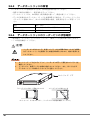
3.2.4
データカートリッジのリーダーピンの状態確認
ご使用前に、データカートリッジのリーダーピン(磁気テープ先頭に取り付けられたピ
ン)の状態を確認してください。
注意
・ リーダーピンが外れている、変形している、または衝撃が加わったなどの異常
なデータカートリッジを使用すると本製品が故障しますので、絶対に使用しな
いでください。
`
`
カートリッジ・ドアをスライドして、リーダーピンが正しく固定されていることを
確認してください。
リーダーピン、磁気テープには絶対に触らないでください。また、ほこりなどが
データカートリッジ内部に入らないように注意してください。
カートリッジ・ドア
○リーダーピンが正しく固定されている
×リーダーピンが外れている
カートリッジ・ドアをスライドし、リーダーピンの状態を確認してください。
30
4
クリーニングについて
この章では、本製品のクリーニングについて説明しています。
本製品にクリーニングカートリッジを挿入すると、自動的に磁気ヘッドのクリーニングが
行われます。クリーニングは、約 2 ~ 4 分かかります。クリーニング動作が完了すると、
クリーニングカートリッジは排出されます。
`
4.1
本製品は、データの書き込みや読み取りに磁気ヘッドを使用しています。磁気ヘッドがほ
こりやゴミで汚れていると、データの書き込みや読み取りが正常に行われません。
また、データカートリッジの寿命が短くなる、磁気テープ表面に傷が付き使用できなくな
るなどの不具合が発生します。このようなことを未然に防ぐために、クリーニングカート
リッジで清掃してください。
使用できるクリーニングカートリッジ
本製品には次のクリーニングカートリッジをお使いください。サプライ品については、
「5 サプライ品」(→ P.33)を参照してください。
品名
Ultrium 1 クリーニングカートリッジ U
商品番号
0160280
購入単位
1巻
備考
ユニバーサルクリーニング
カートリッジ(*)
*:本製品では、Ultrium1 クリーニングカートリッジ(商品番号:0160290)は使用できません。
`
`
`
CLEAN LED が点灯している場合、クリーニングが必要です。クリーニングカートリッジ
を挿入し、クリーニングを行ってください。
クリーニングカートリッジは、50 回まで使用できます。使用回数が 50 回に満たない場合で
も、購入後 5 年以上経過したクリーニングカートリッジは、新しいクリーニングカート
リッジと交換してください。
クリーニングカートリッジをセットしても、自動的に排出されず、CLEAN LED が高速点
滅する場合は、新しいクリーニングカートリッジと交換してください。
J
4 クリーニングについて 31
4.2
ヘッドクリーニングについて
■ クリーニングカートリッジの使用回数の管理
クリーニングカートリッジには寿命があり、使用可能回数は 50 回です。クリーニング媒
体に添付されているラベルなどを活用して、使用回数を管理してください。
寿命が過ぎたクリーニングカートリッジを使用した場合、CLEAN LED が高速点滅し、ク
リーニングカートリッジは排出されません。このときクリーニングは行われませんので、
新しいクリーニングカートリッジに交換して、再度磁気ヘッドのクリーニングを行ってく
ださい。
使用開始日:2007年1月31日
使用回数 :
クリーニングカートリッジラベル記入例
■ 磁気ヘッドのクリーニングの実施時期
磁気ヘッドのクリーニングは、次の場合に行ってください。
・3ヵ月に一度(定期クリーニング)
および
・CLEAN LEDが点灯した場合(ヘッドクリーニング要求)
・ 定期クリーニング
磁気ヘッドへの汚れの堆積の予防処置として定期的なヘッドクリーニング(3 か月に 1
回程度)をお勧めします。本製品をまったく使用していない場合でも、動作確認を兼ね
て定期的なクリーニングをお勧めします。
・ ヘッドクリーニング要求
本製品は、次の場合にヘッドクリーニング要求状態(CLEAN LED が点灯)となること
があります。
クリーニング要求状態になった場合、クリーニングカートリッジを挿入してクリーニン
グを行ってください。
- 突発的に磁気ヘッドにゴミが付いた場合
クリーニング実施後、設置環境の再確認をお願いします。
→「1.1 設置環境の確認」(P.9)
- データカートリッジ内の磁気テープが傷んでいる場合
クリーニング実施後、新しいデータカートリッジと交換してください。
- 一定時間(100 時間)
、バックアップ/リストアなどの動作を行った場合
32
5
サプライ品
本製品のサプライ品について説明します。
サプライ品には次のものがあり、富士通純正品を使用されることをお勧めします。
品名
商品番号
出荷単位
備考
200GB(*1)
Ultrium2 データカートリッジ
0160310
5巻
容量
Ultrium3 データカートリッジ
0160320
5巻
容量 400GB(*1)
Ultrium1 クリーニングカートリッジ U
0160280
1巻
ユニバーサルクリーニング
カートリッジ(*2)
*1:データ圧縮機能を使わない場合の値です。記憶容量は、1GB=1000 × 1000 × 1000byte 換算です。
*2:本製品では、Ultrium1 クリーニングカートリッジ(商品番号:0160290)は使用できません。
富士通サプライ品は、富士通コワーコ株式会社の取り扱い品です。
問い合せ先:富士通コワーコ株式会社
お客様総合センター:0120-505-279 月~金 9:00 ~ 17:30(土、日、祝日、年末年始除く)
http://jp.fujitsu.com/group/coworco
また、データカートリッジの取り扱いについては、上記ホームページ内の『サプライ商
品』→『データメディア』→『LTO テープ』の『LTO Ultrium カートリッジテープ説明書』
も参照してください。
J
5 サプライ品 33
6
バックアップ運用上の注意
この章では、本製品のバックアップ運用上の注意事項について説明しています。
■ バックアップ後のデータカートリッジの排出について
データカートリッジを本製品内に入れたままにしないでください。データカートリッジは
使用する時間に応じて消耗しますので、寿命が短くなります。また、データカートリッジ
は本製品内では磁気記録面が露出しており、この状態が長く続くと浮遊塵埃の影響を受け
やすくなります。バックアップ運用直前にデータカートリッジを入れ、バックアップ運用
が終了したらすぐにデータカートリッジを取り出してください。
■ データの圧縮率について
本製品には、ハードウェアによるデータの圧縮機能があります。
データの圧縮率は、目安として 2 倍程度としておりますが、データの内容により圧縮率は
変化します。ソフトウェアにより圧縮処理されたデータでは、本製品による圧縮効果は期
待できません。
また、バックアップソフトウェアによってはデータ転送前にソフトウェアによりデータを
圧縮する機能がありますが、本製品のハードウェアによるデータ圧縮機能を有効にしてい
る場合は、ソフトウェアによるデータ圧縮を行わないでください。
■ バックアップ性能/容量について
次の要因により、バックアップ性能および 1 巻あたりに記録できるバックアップ容量が変
化します。
・ ご使用されるデータカートリッジの記録面の状態(消耗、汚れなど)
・ 本製品の磁気ヘッドの汚れ状態
・ データの圧縮率
・ サーバの負荷状況
■ システム構築時の留意事項
同一データカートリッジ 1 巻によるバックアップ運用では、バックアップに失敗した場
合、全データが失われる危険があります。また、バックアップしたデータカセットの磁気
テープが傷つくなどした場合にデータが復元できなくなります。複数のデータカートリッ
ジによるバックアップ運用を行うことにより、トラブル発生時の被害を最小限にできま
す。
例)曜日ごとのデータカートリッジを準備しバックアップ運用する。
34
7
トラブルシューティング
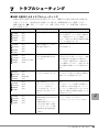
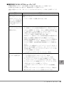
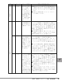
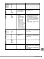
■ LED の表示によるトラブルシューティング
LED の表示の意味と対処方法を次の表に示します。問題がある場合は次の表の対処方法
に従ってください。本対処方法で回復しない場合は、修理相談窓口にご連絡ください。
LED の表示は、●:消灯、○:点灯、◎:点滅(1 秒に 1 回)、☆:高速点滅(1 秒に 4
回)を意味します。
LED の表示
状態
対処方法
本製品に電源が入っていな
い。
サーバ本体に電源が入っているのに本状
態となる場合は、サーバ本体と本製品が
正しく接続されていることを確認してく
ださい。回復しない場合は本製品が故障
している可能性があります。
:点灯
ACTIVITY :消灯
:消灯
ERROR
:消灯
CLEAN
本製品に電源が入っており
使用可能な状態です。
なし。
正常な状態です。
:点灯
電源投入時の自己診断テス
トおよび初期化動作を実行
しています。
電源投入直後の場合、POWER LED のみ
が点灯になるまで待ってください。電源
投入直後以外で本状態となる場合は、
サーバ本体と本製品が正しく接続されて
いるか確認してください。回復しない場
合は本製品が故障している可能性があり
ます。
電源投入時の自己診断テス
トでエラーが発生しました。
サーバ本体をシャットダウンし再起動し
てください。回復しない場合は本製品が
故障している可能性があります。
本製品が動作中です(デー
タカートリッジのロード・
アンロード、巻き戻し、
データの書き込み、データ
の読み出しなどを行ってい
ます)
。
なし。
データカートリッジが挿入され動作して
いる場合は、正常な状態です。データ
カートリッジが挿入されていないのに本
状態となる場合は本製品が故障している
可能性があります。
クリーニングが必要です。
CLEAN LED が点灯するのは
次の場合です。
・ 本製品自身がクリーニン
グを必要と判断した場合
・ データカートリッジの動
作時間が 100 時間を越え
クリーニングカートリッジを使用してク
リーニングを行ってください。
→「4 クリーニングについて」(P.31)
POWER
:消灯
ACTIVITY :消灯
ERROR
CLEAN
:消灯
:消灯
POWER
POWER
ACTIVITY :点滅
ERROR
CLEAN
POWER
:点滅または消灯
:点滅
:点灯
ACTIVITY :消灯
ERROR
CLEAN
POWER
:高速点滅
:点灯
:点灯
ACTIVITY :点滅
ERROR
CLEAN
:消灯
:消灯
:点灯
ACTIVITY :消灯
:消灯
ERROR
:点灯
CLEAN
POWER
J
た場合。
7 トラブルシューティング 35
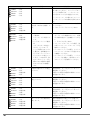
LED の表示
対処方法
クリーニング動作中です。
クリーニングカートリッジが排出される
まで待ってください。クリーニングカー
トリッジが挿入され、ヘッドクリーニン
グが行われていると本状態となります。
ヘッドクリーニングが終わるとクリーニ
ングカートリッジは自動的に排出されま
す。
:点灯
クリーニングカートリッジ
が寿命(50 回以上使用)で
す。
新しいクリーニングカートリッジを使用
してください。
→「4 クリーニングについて」(P.31)
:点灯
ACTIVITY :消灯
:高速点滅
ERROR
:高速点滅
CLEAN
・ クリーニングカートリッ
ジ使用時
クリーニングに失敗しま
した。
・ データカートリッジ使用
時
メディアエラーが発生し
ました。データカート
リッジが挿入されていな
い場合は、前回使用した
データカートリッジでメ
ディアエラーが発生して
います。この表示は、別
のデータカートリッジを
挿入するか本製品の電源
がオフになるまで継続し
ます。
・ クリーニングカートリッジ/データ
カートリッジに破損がないこと、本製
品で使用可能なことを確認してくださ
い
→「5 サプライ品」(P.33)
・ クリーニングカートリッジの場合、別
の新しいクリーニングカートリッジを
使用してください。
・ データカートリッジの場合、ライトプ
ロテクトスイッチが正しい位置にある
か確認してください。
・ データカートリッジの場合、ヘッドク
リーニングを実施し、別の新しいデー
タカートリッジを使用してください。
:点灯
ACTIVITY :消灯
:高速点滅
ERROR
:消灯
CLEAN
回復不可能なエラーが発生
しました。
可能な場合、サーバをシャットダウンし
再起動してください。
回復しない場合は本製品が故障している
可能性があります。
:点灯
ACTIVITY :消灯
:点灯
ERROR
:消灯
CLEAN
ファームウェアのエラーが
発生しました。
可能な場合、サーバをシャットダウンし
再起動してください。
回復しない場合は本製品が故障している
可能性があります。
ファームウェアの更新中で
す。
通常の動作時には発生しない状態です。
可能な場合、サーバをシャットダウンし
再起動してください。
回復しない場合は本製品が故障している
可能性があります。
ファームウェアの更新が失
敗しました。
通常の動作時には発生しない状態です。
可能な場合、サーバをシャットダウンし
再起動してください。
回復しない場合は本製品が故障している
可能性があります。
POWER
ACTIVITY :点灯
ERROR
CLEAN
:消灯
:高速点滅
POWER
POWER
POWER
:点灯
ACTIVITY :高速点滅
:点滅
ERROR
:高速点滅
CLEAN
POWER
:点灯
ACTIVITY :高速点滅
:高速点滅
ERROR
:高速点滅
CLEAN
POWER
36
状態
:点灯
POWER
ACTIVITY :点灯
:消灯
ERROR
:点灯
CLEAN
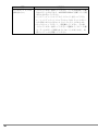
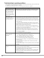
■ 動作状況によるトラブルシューティング
本製品を使用していて、正常に動作しない場合の対処方法について説明します。
本対処方法で回復しない場合は、修理相談窓口にご連絡ください。
LED の状態については、
「2.1 フロントパネルおよびコネクタ」(→ P.23)を参照してくだ
さい。
現象
対処方法
本製品が動作しない
(データカートリッジ
を挿入してもロードし
ない、サーバ本体の電
源を入れても本製品の
Power LED が点灯しな
い、など)
。
電源ケーブル・SCSI ケーブルが正しく取り付けられているかを
確認してください。
→「1 サーバ本体への搭載と導入方法」
(P.8)
本製品が OS、バック
アップソフトウェアで
認識されない。
・ 電源ケーブル、SCSI ケーブルが正しく取り付けられているこ
と、SCSI ケーブルに SCSI 終端抵抗が正しく取り付けられて
いることを確認してください。また、本製品の SCSI-ID が正
しく設定されているかを確認してください(同じバス上の他
の製品と同じ SCSI-ID に設定されていないこと)。
→「1 サーバ本体への搭載と導入方法」(P.8)
・ SCSI カード、SCSI ケーブル、SCSI 終端抵抗が本製品および
SCSI バスの種類と互換性があるかを確認してください。
・ 本製品が SCSI BIOS やオペレーティングシステムで認識され
ているかを確認してください(Windows のデバイスマネー
ジャなどで確認。"QUANTUM ULTRIUM 3" として認識され
ます)
。
・ SCSI カードと本製品がバックアップソフトウェアでサポート
されているかを確認してください。また、デバイスドライバ
が必要な場合、正しいデバイスドライバがインストールされ
ているかを確認してください。
→「1.4 デバイスドライバのインストール」
(P.12)
カートリッジを挿入し
てもすぐに排出され
る。
・ 使用可能なデータカートリッジかを確認してください。
→「3.1 使用できるデータカートリッジ」(P.28)
→「4.1 使用できるクリーニングカートリッジ」(P.31)
・ データカートリッジが正しい向きかを確認してください。
→「2.2 データカートリッジの取り付け/取り外し」(P.26)
・ データカートリッジに破損がないこと、リーダーピンが正し
く固定されていることを確認してください。
→「3.2.4 データカートリッジのリーダーピンの状態確認」
(P.30)
・ 別の新しいデータカートリッジを使ってください。問題ない
場合は元のデータカートリッジを使わないでください。
J
7 トラブルシューティング 37
38
現象
対処方法
データカートリッジが
排出されない。
・ イジェクトボタンを押してください。テープの巻き戻しに数
分かかることがあります。ACTIVITY LED が点滅している間
はそのまま待ってください。
・ バックアップソフトウェアからイジェクトを行ってくださ
い。バックアップソフトウェアによってはイジェクトボタン
による取り出しをできないようにしていることがあります。
・ サーバをシャットダウンし、再起動してください。その後、
イジェクトボタンを押してください(電源オフ/オンした場
合、データが正しく記録されていないことがあります)。再
度バックアップを実施してください。
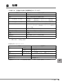
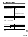
8
仕様
この章では、本製品の仕様と設置環境を示しています。
項目
機能・仕様
品名
内蔵 LTO3 ユニット
型名
PG-LT302/PGBLT302/PGBLT302C
データ記憶容量(非圧縮)
400GB(*1)(Ultrium3 データカートリッジ使用時)
200GB(*1)(Ultrium2 データカートリッジ使用時)
デ-タ転送速度(非圧縮)
64MB/s(*2)(Ultrium3 データカートリッジ使用時)
データ・フォーマット
Ultrium2、Ultrium3 フォーマット(使用するデータ
カートリッジによる。Ultrium1 フォーマットは読み込
みのみ可能)。
インタフェース
Ultra 160 SCSI
外形寸法(単位:mm)
横幅 149.1 ×高さ 43.1 ×奥行き 222.6
質量
1.7kg
消費電力
最大 36W(スタンバイ時 12.5W)
発熱量
最大 129.6kJ/h
*1:1GB=1000 × 1000 × 1000byte 換算
*2:1MB=1024 × 1024byte 換算
設置環境条件を次に示します。
項目
温度
設置条件
動作時
10 ~ 35 ℃
休止時
-5 ~ 55 ℃
湿度
動作/休止時
20 ~ 80%RH(ただし、結露しないこと)
温度勾配
動作/休止時
15 ℃ /hr 以下(ただし、結露しないこと)
最高湿球温度
26 ℃
浮遊ほこり
0.15mg/m3 以下
設置環境については、
「1.1 設置環境の確認」(→ P.9)も併せて参照してください。
J
8 仕様 39
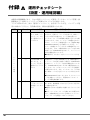
付録 A
運用チェックシート
(設置・運用確認編)
本製品は精密機器であり、日々の運用(クリーニング運用・データカートリッジ管理・設
置環境など)を誤るとバックアップ失敗などのトラブルが発生します。
トラブル防止のため、次の「運用チェックシート」を活用していただき、バックアップ運
用にお役立てください。各作業内容は、弊社の推奨運用になります。
分類
ク
リ
|
ニ
ン
グ
運
用
40
No.
チェック
チェック項目
1
□
3 か月に一度の割
合で、磁気ヘッド
のクリーニングを
行う運用になって
いますか?
本製品は、使用・未使用に関わらず磁気ヘッドが汚
れるため、定期クリーニングが必要です。磁気ヘッ
ドなどが汚れた状態では、テープ表面を傷つけ、
データカートリッジが短期間で使用できなくなる場
合があります。なお、メンテナンス時期を忘れない
ために、バックアップ環境支援ツール『Fujitsu Tape
Maintenance Advisor』をご使用していただき、メン
テナンス時期をオペレータの方へ自動通知すること
ができます。なお、本製品自体にもテープ走行 100
時間ごとに CLEAN LED を点灯して、クリーニング
を促す機能を持っています。
●本製品は、3 か月に一度クリーニングしてくださ
い。
2
□
CLEAN LED が点
灯したとき、ク
リーニングを行う
運用になっていま
すか?
本製品はテープ走行 100 時間ごとや、動作状態から
クリーニングが必要と判断した場合に CLEAN LED
を点灯して、クリーニングを促す機能を持っていま
す。CLEAN LED が点灯したままで使用を続けると、
データカートリッジやバックアップデータを損傷す
る場合があります。また、データカートリッジが消
耗し磁気ヘッドなどを汚していることが考えられま
す。
● CLEAN LED が点灯したときは、すぐにクリーニ
ングを実施してください。再発時はデータカート
リッジ交換を検討願います。
3
□
交換用のクリーニ
ングカートリッジ
を用意しています
か?
クリーニングカートリッジは、本製品では、使用回
数:50 回、使用期間:5 年のどちらか早い方を目安
に交換が必要です。
●運用に合わせて定期的に交換するようにしてくだ
さい。
●クリーニングカートリッジを使い切った場合のた
めに、交換時期が近づいたときは新しいクリーニン
グカートリッジを用意しておいてください。
解説/作業内容(●)
分類
No.
チェック
チェック項目
ク
リ
|
ニ
ン
グ
運
用
4
□
クリーニングカー
トリッジを使い
切った場合(ク
リーニングカート
リッジを入れたと
き、CLEAN LED
が高速点滅し排出
されない場合)
に、交換する運用
になっています
か?
本製品にクリーニングカートリッジを入れたとき
に、自動的に排出されず、CLEAN LED が高速点滅
するときは、クリーニングカートリッジを使い切っ
ています。
●上記のような場合は新しいクリーニングカート
リッジに交換してください。
5
□
データカートリッ
ジに使用開始日を
書いていますか?
(交換目安:1年)
データカートリッジは消耗品です。消耗したデータ
カートリッジは磁気テープ表面が傷つき、磁気ヘッ
ド汚れの増加、媒体エラー多発などの不具合の原因
となります。データカートリッジの消耗によるバッ
クアップ失敗を防止するため、富士通純正品で、使
用期間:1 年、使用回数:1000 回のどちらか早い方
を目安に交換が必要です。
●上記に該当する場合は、新しいデータカートリッ
ジに交換してください。データカートリッジは富士
通純正品を使用されることをお勧めします。
6
□
バックアップ時、
すぐに CLEAN
LED が点灯するよ
うな場合や、デー
タカートリッジ排
出遅延/ロード不
可の際は、データ
カートリッジを交
換する運用になっ
ていますか?
データカートリッジが寿命に達している場合、バッ
クアップ中に磁気ヘッド汚れなどを検出し、
CLEAN LED が点灯しやすくなります。また、デー
タカートリッジの排出に時間がかかったり、データ
カートリッジがロードできなくなる場合がありま
す。
●このような現象の場合、使用回数/期間に関わら
ず、データカートリッジを新しいものに交換し様子
を見てください。その際、他のデータカートリッジ
の使用回数/期間をチェックし、交換周期に近づい
ているデータカートリッジは傷みが進行している場
合がありますのですべて交換することをお勧めしま
す。
7
□
バックアップ直前
にデータカート
リッジをセット
し、バックアップ
直後にデータカー
トリッジを取り出
して専用ケースに
入れて保管する運
用ですか?
また、スケジュー
ルでのバックアッ
プ時は確実に自動
排出されるよう設
定していますか?
データカートリッジのデータ記録面は、本製品内で
露出し、テンション(張力)により磁気ヘッドなど
と接触しています。この状態が長く続くと浮遊塵埃
やテンションの影響を受けやすく、データカート
リッジの寿命低下/バックアップ時のエラー発生/
本製品の故障などの原因となることがあります。
●データカートリッジは使用前に本製品にセット
し、使用後はただちに取り出して、ケースに入れて
保管してください。
●スケジュールでのバックアップなど、バックアッ
プを自動で行う場合は、「1.6 バックアップジョブの
設定(自動排出の設定)」
(→ P.18)に従って自動的
に排出するように設定してください。
デ
|
タ
カ
|
ト
リ
ッ
ジ
管
理
解説/作業内容(●)
J
付録 A 運用チェックシート (設置・運用確認編) 41
分類
No.
チェック
チェック項目
設
置
環
境
8
□
本製品が内蔵され
たサーバ本体の周
囲はほこりの少な
い環境ですか?
解説/作業内容(●)
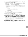
本製品は、データ記録面が内部で露出するため、設
置環境(特に塵埃)の影響を受けやすくなっていま
す。一般的に、床面に近いほど塵埃濃度は高くなる
ので、机上など床面より離れた場所への設置をお勧
めします。
● " 避けて頂きたい設置例 " を参考に、よりほこり
の少ない環境に設置するよう配慮をお願い致しま
す。
[避けていただきたい設置例]
・ 本製品を床に直置き
・ 人通りの多い場所
・ 開放されるドアや窓の近く。特に土埃や車の排気
ガス、などの外部の影響を受ける場所
・ 空気の取り込み口、吹き出し口の近く。(空調、
エアコン、換気扇、などに注意)
・ タバコの煙の影響を受ける場所(本製品が設置さ
れた部屋での喫煙禁止)
・ プリンタの近くでトナーの影響を受ける場所
・ コピー機、シュレッダー、FAX、など、紙を扱う
装置の近くで、紙の粉の影響を受ける場所
設置後、数か月でデータカートリッジ投入口や周囲
に塵埃が堆積するような場合には設置場所を見直し
てください。
9
□
本製品が内蔵され
たサーバ本体の電
源を切る場合や再
起動時には、デー
タカートリッジを
取り出す運用に
なっていますか?
本製品は、データカートリッジ取り出し時にデータ
カートリッジに管理情報の書き込み処理を行いま
す。このため、本製品にデータカートリッジを入れ
たまま電源を切断すると管理情報が書き込まれない
異常なフォーマットのデータカートリッジが生成さ
れ、データリストア失敗などの問題に繋がります。
●サーバ本体の電源を切るときは、あらかじめ本製
品からデータカートリッジを取り出してから電源を
切断してください。
●スケジュールでのバックアップなど、バックアッ
プを自動で行う場合は、「1.6 バックアップジョブの
設定(自動排出の設定)」(→ P.18)に従って自動的
に排出するように設定してください。
10
□
バックアップ業務
には複数本のデー
タカートリッジを
用い、世代管理す
る運用になってい
ますか?(毎回同
じデータカート
リッジを使用する
運用になっていま
せんか?)
1巻のデータカートリッジでバックアップを繰り返
すような運用では、バックアップ失敗時や、バック
アップデータを書き込んだデータカートリッジが破
損したときに、一時的に重要なバックアップデータ
が無くなる状態になります。
●バックアップ業務には複数本のデータカートリッ
ジを用い、世代管理する運用にしてください。
そ
の
他
42
付録 B
B.1
Tape Maintenance
Advisor について
はじめに
最近では、テープ装置をデータのバックアップのために使用されるお客様も非常に増えて
きています。テープ装置はハードディスクなどと異なり、定期的なメディアの交換やバッ
クアップ装置のクリーニングなどメンテナンスが必要な装置です。このことが認識されな
いまま使用され、「バックアップ作業が失敗する」「いざという時にデータが復元できな
い」といったトラブルが生じる事例が散見されます。
そこで、弊社では、このようなトラブルを起こさないために、サーバ本体に接続されてい
るテープ装置のメンテナンス時期をオペレータに通知する Fujitsu Tape Maintenance Advisor
(以降「Tape Maintenance Advisor」と表記します)(*) を提供いたします。
* :本ソフトウェアは、
「Tape Maintenance Checker」の後継製品です。
B.2
Tape Maintenance Advisor 導入のメリット
B.2.1
提供する主な機能
・ PRIMERGY に接続しているテープ装置の決められたメンテナンス時期に、オペレータ
の端末(Windows)に Messenger 通知し、メンテナンス作業を促します。
・ オペレータがメンテナンス作業を実施しない場合には、翌日もメンテナンスを促す
Messenger が通知されます。
・ オペレータが一週間以上メンテナンス作業を実施しない場合には、Messenger 通知とと
もに、イベントログに「警告」のログを残します。
以上の機能により、システム管理者は当該サーバのイベントログ監視を行うだけで、テー
プ装置のクリーニング運用の実態を把握することができます(弊社ソフトウェア:System
Walker などを併用すると効果的です)。
J
付録 B Tape Maintenance Advisor について 43
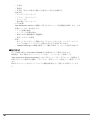
B.2.2
メリット
本ソフトウェアを導入すると、次のような利点があります。
分類
導入前
導入後
・ テープ装置の定期的なクリーニ
ング作業を行っていない。
・ あらかじめ設定された周期で、
クリーニングを促すメッセージ
がポップアップするので、ク
リーニング作業を忘れない。
・ 週に一度、クリーニングをする
ことになっているが忘れてしま
い、クリーニングしなくなって
しまう。
・ クリーニング作業を怠ると翌日
もメッセージが通知される。
システム管理
者は?
・ 現地のオペレータがクリーニン
グ運用を実施しているかを把握
できない。
・ システム管理者が、定期的なク
リーニングの必要性を理解して
いない。
クリーニングしていないと当該
サーバのイベントログに残るの
で、イベントログを監視すれば、
現地オペレータのクリーニング作
業の実施具合が把握できる。
バックアップ
業務は?
テープ装置の磁気ヘッド周囲に塵
埃が堆積
結果として
・ バックアップ業務がたびたび失
敗する。
・ バックアップしたデータカート
リッジを傷つけてしまい、デー
タの復元ができない事象も発
生。
テープ装置はメンテナンスされた
状態
結果として
・ バックアップ業務の安定度が向
上する。
現地のオペ
レータは?
44
B.3
製品概要
■ 製品名
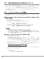
使用する OS に応じて、2 つの製品があります。
・ Fujitsu Tape Maintenance Advisor for Windows
・ Fujitsu Tape Maintenance Advisor for Linux
■ 動作環境
・ OS
- Windows の場合
・ Windows 2000 Server(Service Pack 4 以降)
・ Windows Server 2003 / Windows Server 2003 x64(*)
*:Windows Server 2003,Enterprise Edition for Itanium-Based Systems では動作しませ
ん。
- Linux の場合
・ Linux v.3
・ Linux v.4 / Linux v.4 for EM64T
・ 動作ハードウェア
PRIMERGY シリーズ
・ 対応サーバ
Tape Maintenance Advisor が使用可能なサーバの場合、インターネット情報ページ
(http://primeserver.fujitsu.com/primergy/)内の『ダウンロード』→『ダウンロード検索』
で、サーバの製品名および型名を選択し、カテゴリに「添付ソフト」を指定して検索す
ると、Tape Maintenance Advisor が検索結果に出てきます。検索結果に出てこない場合
は、そのサーバ/ OS では Tape Maintenance Advisor の動作がサポートされていません。
・ メモリ使用量
5MB 以下
・ CPU 使用率
1%以下
`
`
Windows では、本ソフトウェアはサービスを1つ使用します。
Linux では、X-Window(GNOME)が導入され、ログインされている必要がありま
す。
J
■ 主な機能
・ メンテナンス時期の通知
- 接続されているテープ装置のメンテナンス時期を通知します。
- テープ装置が複数接続されている場合でも、それぞれの装置ごとに通知できます。
- テープ装置があらたに接続された場合も自動的に認識して通知します。
・ 通知方法の設定
テープ装置ごとにメンテナンスの通知周期と通知方法を設定できます。設定可能な通知
周期と通知方法は、次のとおりです。
- 通知周期
付録 B Tape Maintenance Advisor について 45
・ 日単位
・ 週単位
・ 月単位(日付での設定と曜日での設定のいずれかを選択可)
- 通知方法
・ ポップアップメッセージ
・ アイコン(タスクトレイ)
・ イベントログ
・ 他の端末へのメッセージ
- ログの記録
Tape Maintenance Advisor の起動から終了までのイベント発生履歴を記録します。主な
記録イベントは、次の通りです。
・ テープ装置の検出
・ メンテナンス時期の通知
・ 通知に対する確認操作の実施操作
・ 発生したエラーの情報
- 特長
・ 本ソフトウェアはテープ装置に対してアクセスしないため、バックアップソフト
ウェアなど他のソフトウェアとの競合を気にする必要がありません。
・ Windows Messenger の機能を使用して、離れた端末へメッセージ送信が可能です。
■ 配付形式
サーバ本体に添付の ServerStart CD-ROM 内に収録されている場合があります。
最新版は、次の手順でダウンロードしてください。インターネット情報ページ
(http://primeserver.fujitsu.com/primergy/)内の『ダウンロード』→『ダウンロード検索』で
お使いのサーバの製品名を選択し、カテゴリに「添付ソフト」を指定して、検索してくだ
さい。
同時にダウンロードされるソフトウェアの操作説明書をよくご覧になり使用してくださ
い。
46
付録 C
C.1
Windows 自動システム回復
(Automated System
Recovery)について
Windows 自動システム回復ディスクについて
Windows Server 2003 / Windows Server 2003 x64 において、Windows 自動システム回復機能
(Automated System Recovery、以降 ASR)を使用するためには、Windows 自動システム回復
ディスク(Windows 自動システム回復機能用にシステムデータをバックアップした際に作
成したフロッピーディスク)に、本製品のデバイスドライバを追加しておく必要がありま
す。
ここでは、Windows 自動システム回復ディスク(以降、ASR フロッピーディスク)に本製
品のデバイスドライバを追加する方法を説明します。
`
以降の作業は隠しファイル・フォルダも含めたすべてのファイル・フォルダが表示されて
いる必要があります。また、ファイルの拡張子が表示される設定で行ってください。
1 本製品に添付のドライバフロッピーディスク(またはダウンロードしたデ
バイスドライバ)の全ファイルを作業用のフォルダ(ドライバ格納フォル
ダ)にコピーします。
2 各 OS に応じて、次の 3 つのファイルを ASR フロッピーディスクにコ
ピーします。
`
フォルダはコピーしないでください。
・ Windows Server 2003 の場合
・ ドライバ格納フォルダ \LTO3HH\qltowin.inf
・ ドライバ格納フォルダ \LTO3HH\qltowin.cat
・ ドライバ格納フォルダ \LTO3HH\i386\qltowin.sys
・ Windows Server 2003 x64 の場合
・ ドライバ格納フォルダ \LTO3HH\qltowin.inf
・ ドライバ格納フォルダ \LTO3HH\qltowin.cat
・ ドライバ格納フォルダ \LTO3HH\amd64\qltowin.sys
J
付録 C Windows 自動システム回復(Automated System Recovery)について 47
3 ASR フロッピーディスク内の asr.sif ファイルに次の記述を追加します。
ノートパッド(メモ帳)などで、次の 4 行([INSTALLFILES]を含む)を asr.sif
ファイル の "DISKS.GPT" セクションの下に追加してください。
=+056#..(+.'5?
#54(.122;SNVQYKPU[U6'/2>SNVQYKPU[U3WCPVWOZ
#54(.122;SNVQYKPKPH6'/2>SNVQYKPKPH3WCPVWOZ
#54(.122;SNVQYKPECV6'/2>SNVQYKPECV3WCPVWOZ
4 コマンドプロンプトから、ASR フロッピーディスクにラベルを付けます。
ラベルが書かれているかどうかは、プロパティで確認してください。
[例] C:\> label a: ASR
5
winnt.sif ファイルを作成し、次の記述を入力します。
ノートパッド(メモ帳)などで、winnt.sif ファイルを作成し、次の 9 行の記述を入
力して ASR フロッピーディスクに保存してください。
=&CVC?
#WVQ2CTVKVKQP
/U&QU+PKVKCVGF
7PCVVGPFGF+PUVCNN;GU
=7PCVVGPFGF?
1GO2TGKPUVCNN;'5
1GO(KNGU2CVJC>
1GO2P2&TKXGTU2CVJ6'/2
6 すべてのファイルを閉じて、次の 7 つのファイルが ASR フロッピーディ
スクに存在しているか確認します。
#>CUTUKH
#>CUTRPRUKH
#>SNVQYKPECV
#>SNVQYKPKPH
#>SNVQYKPU[U
#>UGVWRNQI
#>YKPPVUKH
以上で、ASR フロッピーディスクに本製品のデバイスドライバが追加されました。
システム復元の際には、このフロッピーディスクを使用してください。
48
C.2
Windows 自動システム回復(ASR)の使用方
法
ASR の使用方法について説明します。
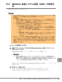
`
Windows 標準ではないドライバ(例:RAID ドライバ、SCSI ドライバなど)が必要
な場合には、ASR を実施する前に次の準備を行ってください。
【事前準備】
1. Windows 標準ではないドライバのドライバフロッピーディスクを作成します
(手順 2 で使用)
。作成方法は、サーバ本体の添付の『ユーザーズガイド』また
は RAID カードの『取扱説明書』を参照してください。
2. ASR 復元時の途中でドライバファイルを要求されたときに使用するドライバ
フロッピーディスクを作成します(手順 3 で使用)
。
1. 【事前準備】の手順 1 で作成したドライバフロッピーディスクの空きス
ペースが 720KB 以上あるかどうかを確認します。ない場合は別途空きフ
ロッピーディスクを準備してください。
2. 各フロッピーディスクに「\$OEM$\TEXTMODE」のフォルダを作成してくだ
さい。
3. 【事前準備】の手順 1 で作成したドライバフロッピーディスクのルート以
下の全ファイルを【事前準備】の手順 2 で作成したフォルダにコピーし
てください。
` FDD ユニット(USB)を使用する場合の注意事項は、
「1.8 デバイスドライバおよび
バックアップソフトウェアの設定・注意事項」の「■ Windows 自動システム回復
(ASR)使用時および BrightStorARCserve Backup の Disaster Recovery Option 使
用時に、フロッピーディスクドライブ(USB)を使用する場合について」(→ P.21)
を参照してください。
1 サーバの電源を入れます。
2 ASR フロッピーディスクおよび Windows Server 2003 インストール
CD をセットします。
Windows Server 2003 インストール CD からシステムが起動します。
`
Windows 標準ではないドライバ(例:RAID ドライバなど)が必要な場合には、
画面の下部に「Press F6 if you need install a third party SCSI or RAID driver …」
とメッセージが表示されます。その場合は、
【F6】キーを押してください。 この
メッセージは約 5 秒間しか表示されませんので注意してください。
J
画面の下部に「Press F2 to run Automated System Recovery (ASR) …」とメッセージが
表示されます。
3 【F2】キーを押します。
このメッセージは約 5 秒間しか表示されませんので注意してください。
手順 2 で【F6】キーを押した場合は、ドライバの読み込みを行います。
付録 C Windows 自動システム回復(Automated System Recovery)について 49
1. 【事前準備】の手順 1 で作成したドライバフロッピーディスクをセットします。
2. 【S】キーを押して、ドライバの情報を読み込みます。
必要なだけ繰り返してください。
3. すべてのドライバの読み込みを完了したら【Enter】キーを押して、読み込み
を終了します。
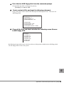
4 以降、表示メッセージに従って、ドライバフロッピーディスク、ASR フ
ロッピーディスクのセットなど、操作を行います。
「ファイル nnn をコピーできません(nnn はファイル名)」と表示された場合は【事
前準備】の手順 2 で作成したドライバフロッピーディスクをセットし、対象ファイ
ルを読み込ませてください。
「Quantum LTO Tape Driver for Windows 2000/XP/2003/Vista 上のファイル "qltowin.sys"
が必要です。ファイルの格納場所へのパスを入力して、
[OK]をクリックしてくだ
さい。」と表示された場合は、コピー元に "c:\temp" を指定して[OK]をクリック
してください。
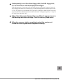
5 「自動システム回復ウィザードの開始」画面が表示されたら、ASR のバッ
クアップデータのデータカートリッジをセットします。
復元が開始されます。
6 復元が完了したら、システムを再起動し、正常に復元できているか確認し
ます。
50
Before Reading This Manual
Thank you for purchasing the Fujitsu Tape Drv LTO3 Ultrium3/Ultrium2 400GB (PG-LT302/
PGBLT302/PGBLT302C).
This manual explains the basic usage of the Tape Drv LTO3 Ultrium3/Ultrium2 400GB (hereafter
referred to as "this product"). Before using this product, read this manual in order to ensure proper
use.
April, 2007
For Your Safety
This manual contains important information, required to operate this product safely.
Thoroughly review the information in this manual before using this product. Especially note the points under "Safety",
and only operate this product with a complete understanding of the material provided.
This manual should be kept in an easy-to-access location for quick reference when using this product.
High Safety
The Products are designed, developed and manufactured as contemplated or general use, including without limitation,
general office use, personal use, household use, and ordinary industrial use, but are not designed, developed and
manufactured as contemplated for use accompanying fatal risks or dangers that, unless extremely high safety is secured,
could lead directly to death, personal injury, severe physical damage, or other loss (hereinafter "High Safety Required
Use"), including without limitation, nuclear reaction control in nuclear facility, aircraft flight control, air traffic control,
mass transport control, medical life support system, missile launch control in weapon system. You shall not use this
Product without securing the sufficient safety required for the High Safety Required Use. If you wish to use this Product
for High Safety Required Use, please consult with our sales representatives in charge before such use.
E
51
Remarks
Warning Descriptions
Various symbols are used throughout this manual. These are provided to emphasize important points
for your safety and that of others. The symbols and their meanings are as follows. Make sure to fully
understand these before reading this manual.
WARNING
Ignoring this symbol could be potentially lethal.
CAUTION
Ignoring this symbol may lead to injury and/or damage this product.
The following symbols are used to indicate the type of warning or cautions being described.
The triangle mark emphasizes the urgency of the WARNING and CAUTION.
Details are described next to the triangle.
A barred circle ( ) warns against certain actions (Do Not).
Details are described next to the circle.
A black circle indicates actions that must be taken.
Details are described next to the black circle.
Symbols
The following are symbols used throughout this manual.
Symbols
Definition
These sections explain prohibited actions and points to note when using this
product. Make sure to read these sections.
These sections explain information needed to operate the hardware and
software properly. Make sure to read these sections.
→
This mark indicates reference pages or manuals.
CD-ROM Drive Description
CD-ROM drive names are shown as [CD-ROM].
Example: [CD-ROM]:\Setup.exe
52
Abbreviations
The following expressions and abbreviations are used to describe the product names used in this
manual.
Product names
Tape Drv LTO3 Ultrium3/Ultrium2 400GB
(PG-LT302/PGBLT302/PGBLT302C)
Expressions and abbreviations
"This product"
Microsoft® Windows Server® 2003, Standard
Edition
Microsoft® Windows Server® 2003, Enterprise
Edition
Microsoft® Windows Server® 2003 R2, Standard
Edition
Windows Server 2003
Microsoft® Windows Server® 2003 R2, Enterprise
Edition
Microsoft® Windows Server® 2003, Standard x64
Edition
Microsoft® Windows Server® 2003, Enterprise
x64 Edition
Microsoft® Windows Server® 2003 R2, Standard
x64 Edition
Windows
Windows Server 2003
x64
Microsoft® Windows Server® 2003 R2, Enterprise
x64 Edition
Microsoft® Windows® 2000 Server
Red Hat® Enterprise Linux® ES (v.3 for x86)
Red Hat® Enterprise Linux® AS (v.3 for x86)
Red Hat® Enterprise Linux® ES (v.4 for x86)
Red Hat® Enterprise Linux® AS (v.4 for x86)
Red Hat® Enterprise Linux® ES (v.4 for EM64T)
Red Hat® Enterprise Linux® AS (v.4 for EM64T)
Windows 2000 Server
Linux v.3
Linux v.4
Linux
Linux v.4 for EM64T
SUSE™ Linux® Enterprise Server 9 for x86
SUSE Linux
BrightStor ARCserve Backup r11.5 for Windows
BrightStor ARCserve Backup
NetVault 7
NetVault
Backup Utility for Windows
Windows Backup
E
53
Safety
For safe use of this product, it is vital that the following warnings are heeded.
Handling this product
WARNING
• Keep the plastic bags used as packing, out of the reach of children.
They could cause suffocation.
• If a foreign object (water, pieces of metal, liquid) falls into this product,
immediately turn off the power and unplug it from the power source.
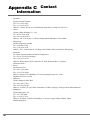
Contact an office listed in "Appendix C Contact Information" (Jpg.92).
Not doing so may cause electric shock and fire. Extreme care should be taken in
households with young children.
• Do not insert or drop foreign objects such as metals or inflammable objects into
openings in this product (ventilating holes, etc.). Doing so may cause electric
shock or fire.
• Do not remodel this product. Doing so may cause electric shock or fire.
54
CAUTION
• Do not disassemble, or take this product apart.
• Do not operate or store this product in the following environments.
- Areas of extremely low temperature
- Areas of extremely high temperature or humidity
- Areas that experience extreme temperature changes
- Areas exposed to magnetic fields
- Areas exposed to shocks or vibration
- Dusty or dirty areas (cigarette smoke, emissions)
- Areas in direct sunlight
- Areas near radiators or other heat sources
• If this product is moved from cold areas to hot areas or if room temperature
suddenly rises, internal condensation may form.
If this product is used after condensation has formed, it may damage this product
or the data cartridge. After a large change in temperature, do not turn on the
power for 1 hour.
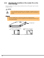
• Eject the data cartridge from this product whenever turning the server off. After
inserting the data cartridges into this product, the magnetic tape recording
surface is exposed. If this situation continues for a long time, dust may stick to the
recording surface or the magnetic tape may be damaged. This might destroy the
data cartridge permanently.
• Eject data cartridges when not using them.
• Do not carry this product with the data cartridge left in it.
• Do not forcibly insert the data cartridge.
• Do not use this product if foreign objects such as metals have fallen into this
product. If some foreign objects have fallen into this product, contact an office
listed in "Appendix C Contact Information" (Jpg.92).
• If the front surface of this product is stained, wipe with a soft, dry cloth or a cloth
wet with water or mild detergent. Do not use benzine, thinner or any volatile
compounds.
Recycle
When scrapping this product, contact an office listed in "Appendix C Contact Information" (Jpg.92).
This product must be disposed of as industrial waste.
E
55
Checking the Items Supplied
Before using the product, check that no supplied or attached items are missing.
If any items are missing, contact an office listed in "Appendix C Contact Information" (Jpg.92).
•
•
•
•
•
•
Tape Drv LTO3 Ultrium3/Ultrium2 400GB (this product) (*1)
Extension power cable (*1)
Screws (x4) (*1)
Cleaning cartridge
Driver floppy disk "PRIMERGY LTO3 UNIT (PG-LT302) Device Driver for Windows"
User's Guide (this document)
*1: For custom made service (PGBLT302/PGBLT302C), items are supplied with the server.
Microsoft, Windows, and Windows Server are trademarks or registered trademarks of Microsoft
Corporation in the United States and other countries.
Linux is a trademark or registered trademark of Linus Torvalds in the United States and other countries.
Red Hat and all Red Hat-based trademarks and logos are trademarks or registered trademarks of Red
Hat, Inc. in the United States and other countries.
SUSE is a trademark of Novell Inc. in the United States and other countries.
All products are copyrights of their respective manufacturers.
All Rights Reserved, Copyright© FUJITSU LIMITED 2007
56
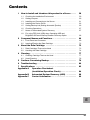
Contents
1 How to Install and Introduce this product to a Server . . . . .
58
1.1
Checking the Installation Environment . . . . . . . . . . . . . . . . . . . . . . .
59
1.2
Setting Jumpers . . . . . . . . . . . . . . . . . . . . . . . . . . . . . . . . . . . . . . . . .
60
1.3
Installing and Connecting to the Server . . . . . . . . . . . . . . . . . . . . . . .
61
1.4
Installing the Device Driver . . . . . . . . . . . . . . . . . . . . . . . . . . . . . . . .
62
1.5
Setting Backup Job (Setting Automatic Ejection) . . . . . . . . . . . . . . .
66
1.6
Checking Operations . . . . . . . . . . . . . . . . . . . . . . . . . . . . . . . . . . . . .
67
1.7
Notes on Automated System Recovery . . . . . . . . . . . . . . . . . . . . . .
67
1.8
For using FDD Unit (USB) when Operating ASR and
BrightStor ARCserve Backup Disaster Recovery Option . . . . . . . . .
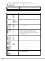
2 Componet Names and Functions . . . . . . . . . . . . . . . . . . . . . .
68
69
2.1
Front Panel and Connector . . . . . . . . . . . . . . . . . . . . . . . . . . . . . . . .
69
2.2
Inserting/Ejecting the Data Cartridge . . . . . . . . . . . . . . . . . . . . . . . . .
72
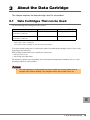
3 About the Data Cartridge . . . . . . . . . . . . . . . . . . . . . . . . . . . .
3.1
Data Cartridges That can be Used . . . . . . . . . . . . . . . . . . . . . . . . . .
3.2
Handling the Data Cartridge . . . . . . . . . . . . . . . . . . . . . . . . . . . . . . .
4 Cleaning . . . . . . . . . . . . . . . . . . . . . . . . . . . . . . . . . . . . . . . . . .
73
73
74
77
4.1
Cleaning Cartridge That can be Used . . . . . . . . . . . . . . . . . . . . . . . .
77
4.2
Head Cleaning . . . . . . . . . . . . . . . . . . . . . . . . . . . . . . . . . . . . . . . . . .
78
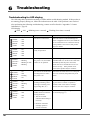
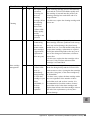
5 Cautions Concerning Backup . . . . . . . . . . . . . . . . . . . . . . . . .
6 Troubleshooting . . . . . . . . . . . . . . . . . . . . . . . . . . . . . . . . . . . .
7 Specifications . . . . . . . . . . . . . . . . . . . . . . . . . . . . . . . . . . . . .
Appendix A
Operation Checksheet
79
80
83
(Installation/Operation Check) . . . . . . . . . . . . . .
Automated System Recovery (ASR) . . . . . . . . .
Contact Information . . . . . . . . . . . . . . . . . . . . . . .
84
88
92
Appendix B
Appendix C
E
57
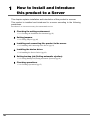
1
How to Install and Introduce
this product to a Server
This chapter explains installation and introduction of this product to a server.
This product is installed and introduced to a server according to the following
procedures.
Procedures 2 to 4 are not necessary for custom made service.
1 Checking the setting environment.
J"1.1 Checking the Installation Environment"(pg.59)
2 Setting jumpers.
J"1.2 Setting Jumpers"(pg.60)
3 Installing and connecting this product to the server.
J"1.3 Installing and Connecting to the Server"(pg.61)
4 Installing the device driver.
J"1.4 Installing the Device Driver"(pg.62)
5 Setting backup job (Setting automatic ejection).
J"1.5 Setting Backup Job (Setting Automatic Ejection)"(pg.66)
6 Checking operations.
J"1.6 Checking Operations"(pg.67)
58
1.1
Checking the Installation Environment
For details about the server installation environment, refer to "Safety Precautions" and "Start Guide".
This product is susceptible to its installation environment (especially dust) because the data recording
surface is exposed inside this product. The closer to the floor, the higher the dust level is in general,
so it is recommended to install this product away from the floor, such as on a desk.
Install this product in environments that are not dusty, referring to the "Examples of installation
environments to avoid".
Examples of installation environments to avoid
• On the floor
• High-traffic areas
• Areas close to open doors/windows especially where affected by the external environment, such as
sandy dust, car exhaust emission, etc.
• Areas close to air ventilating ducts (Be careful of air conditioners, exhaust fans, etc.)
• Areas affected by cigarette smoke (Do not smoke in the room where this product is installed.)
• Areas close to printers and affected by a toner
• Areas close to paper-handling devices, such as copy machines, shredders, or fax machines, that are
affected by paper particles
• Reconsider the installation location if dust accumulates at the data cartridge slot and around the
product within a few months of installation.
Refer to " Safety" (Jpg.54).
E
1 How to Install and Introduce this product to a Server
59
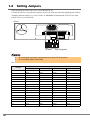
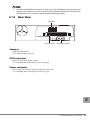
1.2
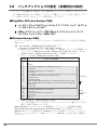
Setting Jumpers
When installing the unit to the server, a SCSI-ID must be set.
A SCSI-ID can be set using the short jumpers on the rear of the unit (the following diagram). Follow
"Installing Internal Options" in "User's Guide" in "PRIMERGY Document & Tool CD" provided
with the server to set a SCSI-ID.
[Rear]
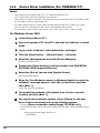
0
1
2
SCSI-ID
`
`
3
Not changeable
Do not change any jumper settings other than the SCSI-ID locations.
Do not install jumpers horizontally.
The SCSI-ID can be set as shown in the following table.
Short jumper
SCSI-ID
0
0
Open
1
2
1
2
3
Open
Open
Open
Short
Open
Open
Open
Open
Short
Open
Open
3
Short
Short
Open
Open
4
Open
Open
Short
Open
5[*]
Short
Open
Short
Open
6
Open
Short
Short
Open
7
Short
Short
Short
Short
8
Open
Open
Open
Short
9
Short
Open
Open
Short
10
Open
Short
Open
Short
11
Short
Short
Open
Short
12
Open
Open
Short
Short
13
Short
Open
Short
Short
14
Open
Short
Short
Short
15
Short
Short
Short
Short
*: Settings at the time of purchase
60
1.3
Installing and Connecting to the Server
For the procedures for installing and connecting this product to the server, refer to the "User's Guide"
in the "Document & Tool CD" provided with the server. If no description is found in the "User's
Guide", refer to the explanation in "Tape Drv LTO2 Ultrium2 200GB (PG-LT201)".
Connect this product to LVD SCSI Interface. Do not connect other devices on the SCSI cable that this
product is connected to.
`
When connecting this product to PRIMERGY TX200 S3, RX600 S2, RX600 S3, RX600 S3
(SAS model) or use the extension power cable supplied with the product.
To install the product in PRIMERGY TX200 S3, install it in the bay placed in the top of the
five inch storage bay.
Connect the SCSI cable
Connect
the power cable
of the server
This product (rear)
Extension power cable
(supplied with this product)
When connecting this product to SCSI Ctrl U160 (PG-128 / PGB128 or PG-1281 / PGB1281), use
the LVD/SE connector. Do not use the connector for the SCSI Ctrl U160 external device with which
this product is connected.
Connect to
this product
Do not use
Do not use
E
1 How to Install and Introduce this product to a Server
61
1.4
Installing the Device Driver
If using this product on Windows, install the device driver according to the following procedure using
the driver floppy disk provided with this product.
For Linux, installing the device driver is not required.
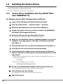
1.4.1
Device Driver Installation (For Any Model Other
than PRIMERGY FT)
For Windows Server 2003 / Windows Server 2003 x64
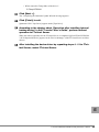
1 Log on to the Windows with administrator privileges.
2 Click the [Start] button → [Control Panel] → [System].
3 Select the [Hardware] tab and click [Device Manager].
4 Double click [Other devices], and then double click [QUANTUM
ULTRIUM 3 SCSI Sequential Device].
5 Select the [Driver] tab and click [Update Driver].
The "Welcome to the Hardware Update Wizard" message appears.
6 When the "Can Windows connect to Windows Update to search for
software?" message appears, click [No, not this time] and then
click [Next >].
7 Click [Install from a list or a specific location] and click [Next >].
8 Click [Search for the best driver in these locations].
9 Check [Include this location in the search], press the [Browse]
button to specify the folder which restored the device driver in the
copy source.
• When using the supplied driver floppy disk (or when the downloaded device driver was
restored in a floppy disk)
A:\LTO3HH
• When using CD-ROMs such as ServerStart
[CD-ROM]:\DRIVERS\tape\LTO3HH
10 Double click [QUANTUM ULTRIUM 3 SCSI Sequential Device].
The "Completing the Hardware Update Wizard" message appears.
11 Click [Finish], and click [Close].
The "Quantum LTO 3 Tape Drive" appears under "Tape Drive".
12 Restart the server.
62
For Windows 2000 Server
1 Log on to the Windows 2000 Server with administrator privileges.
2 Click the [Start] button → [Settings] → [Control Panel].
3 Double click the [System] icon.
4 Select the [Hardware] tab and click [Device Manager].
5 Double click [Other devices], and then double click [QUANTUM
ULTRIUM 3 SCSI Sequential Device].
6 Select the [Driver] tab and click [Update Driver].
The "Welcome to the Device Driver Upgrade Wizard" message appears.
7 Click [Next].
8 Select [Find the best driver for the device], and click [Next].
9 Select [Specify the location], click [Next], set the folder which
restored the device driver in the copy source, and click [OK].
• When using the supplied driver floppy disk (or when the downloaded device driver was
restored in a floppy disk)
A:\LTO3HH
• When using CD-ROMs such as ServerStart
[CD-ROM]:\DRIVERS\tape\LTO3HH
The "The following device driver is found" message appears.
10 Click [Next].
The "Completing the Device Driver Upgrade Wizard" message appears.
11 Click [Complete], and click [Close].
The "Quantum LTO 3 Tape Drive" appears under "Tape Drive".
12 Restart the server.
E
1 How to Install and Introduce this product to a Server
63
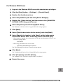
1.4.2
Device Driver Installation (For PRIMERGY FT)
Notes
• This product can be installed only to FT1. It cannot be installed to FT2.
• Two of this product cannot be installed at the same time.
• This product can only be used from a FTvirtual Server (professional-use OS). This product cannot
be used from a CoServer (input-output OS).
• FT model cannot restore the system using Automated System Recovery (ASR) set or system
recovery disk. For restoration, use the recovery CD supplied with the server.
• For installation of the internal 5-inch option, refer to the "User’s Guide" of the FT model.
For Windows Server 2003
1 Install this product to FT1.
2 Turn on the power of FT1 and FT2, and start the CoServer in online
mode.
3 Log on to the CoServer1 with administrator privileges.
4 Click the [Start] button → [Control Panel] → [System].
5 Select the [Hardware] tab and click [Device Manager].
The device manager starts.
6 Double click [Other devices], and then double click [QUANTUM
ULTRIUM 3 SCSI Sequential Device].
7 Select the [Driver] tab and click [Update Driver].
The Setup Wizard appears.
8 When the "Can Windows connect to Windows Update to search for
software?" message appears, click [No, not this time] and then
click [Next >].
Follow the wizard for installation.
9 For installation methods, click [Install from a list or a specific
location] and click [Next >].
10 For search and installation options, select [Search for the best
driver in these locations] and set the following options.
• Uncheck [Search removable media (floppy, CD-ROM, etc.)].
• Check [Include this location in the search] and specify the folder which restored the device
driver.
• When restored in the floppy disk drive A
A:\LTO3HH
64
• When restored in Temp folder of the drive C
C:\Temp\LTO3HH
11 Click [Next >].
The "Completing the Hardware Update Wizard" message appears.
12 Click [Finish] to exit.
[Quantum LTO 3 Tape Drive] appears under [Tape Drive].
13 According to the chapter about "Operation after installing internal
backup device" in the FT model "User’s Guide", perform redirect
operation to FTvirtual Server.
When the redirect operation for the FTvirtual Server is completed, [QUANTUM ULTRIUM
3 SCSI Sequential Device] appears in the "Device Manager" of the FTvirtual Server as Other
devices.
14 After installing the device driver by repeating steps 4 - 12 to FTvirtual Server, restart FTvirtual Server.
E
1 How to Install and Introduce this product to a Server
65
1.5
Setting Backup Job (Setting Automatic
Ejection)
When executing backup automatically, follow the procedures below to set to eject the data cartridge
automatically after backup (even when executing backup manually, make sure to eject the data cartridge after backup).
For BrightStor ARCserve Backup
1. Click the [Options] button in the Backup Manager of the backup job option.
2. Set [Eject Backup Media upon Completion] in the [Operation] tab to "Eject Media".
For Windows Backup
In batch files, etc., add a description that executes the following commands after the backup
commands.
Example: rsm refresh /lf"Quantum LTO 3 Tape Drive"*1
rsm eject /lf"Quantum LTO 3 Tape Drive" /astart
*1: Check the name to be assigned with "Computer Management" → "Storage" → "Removable Storage" → "Libraries"(for Windows Server 2003 / Windows Server 2003 x64) or
"Physical Locations"(for Windows 2000 Server).
[Example of a batch file] (For Windows Server 2003)
Line
Number
Batch File Contents
1:
2:
3:
@echo off
cls
setlocal
4:
5:
6:
7:
8:
9:
10:
11:
12:
13:
rsm inventory /lf"Quantum LTO 3 Tape Drive" /aFULL
timeout /t 60
rsm refresh /lf"Quantum LTO 3 Tape Drive"
timeout /t 60
for /f "Tokens=1-4 Delims=/ " %%i in ('date /t') do set dt=%%i-%%j-%%k-%%l
for /f "Tokens=1" %%i in ('time /t') do set tm=-%%i
set tm=%tm::=-%
set dtt=%dt%%tm%
ntbackup backup @c:\test\test.bks /n "%computername%-%dtt%" /d "daily
%dtt%" /j "daily %dtt%" /p "LTO Ultrium" V:no /R:no /L:f /M normal /RS:NO
/HC:ON /UM
timeout /t 60
14:
15:
16:
17:
rsm refresh /lf"Quantum LTO 3 Tape Drive"
timeout /t 60
rsm eject /lf"Quantum LTO 3 Tape Drive"
timeout /t 60
18:
endlocal
Backup
㪁㪉
Eject
the data
cartridge
*2: To create c:\test\test.bks, start Windows Backup, check the backup target in the [Backup]
tab, and select [Save Selections] in the [Job] menu.
For an example of a Windows Backup batch file, refer to Microsoft Knowledge Base, Article ID:
http://support.microsoft.com/kb/239892/en-us.
For details about how to use the ntbackup, rsm command, refer to Windows help (Click [Start] →
[Help and Support] and search for "ntbackup" or "rsm").
66
When ejecting using Linux commands
Add the description that executes the following command after the backup command in shell
script, etc. (change /dev/st0 to suit the environment).
mt -f /dev/st0 eject
For NetVault
Confirm the device name in the NetVault device management.
In this manual, this product is referred to as "NetVaultSV:1-0.3.0_(QUANTUM_ULTRIUM_3)".
Using the confirmed device name, create a shell script containing the following contents
(tapeeject.sh) in the scripts/users directory in the directory that installed NetVault (/usr/netvault)
(create /usr/netvault/scripts/users/tapeeject.sh).
Example of tapeeject.sh:
/usr/netvault/util/nvdeviceeject -servername NetVaultSV
-devicename "NetVaultSV:_1-0.3.0_(QUANTUM_ULTRIUM_3)"
-servername: Specifies server name to be targeted (example: NetVaultSV)
-devicename: Specifies drive (this product) name to be targeted
(example: NetVaultSV:1-0.3.0_(QUANTUM_ULTRIUM_3))
During backup, check off "Use Post Script" in the "Advanced Option" tab in the NetVault backup
window, and specify "users/tapeeject.sh".
1.6
Checking Operations
Points to note during daily operation are listed in the "Appendix A Operation Checksheet (Installation/Operation Check)" (Jpg.84). Check the operation using the checksheet.
1.7
Notes on Automated System Recovery
Notes on Automated System Recovery (ASR)
Windows Server 2003 and Windows Server 2003 x64 support Automated System Recovery (ASR)
function.
Note the following points for this function.
• Adding a device driver disk for ASR
When using this product for ASR, it is necessary to add a device driver disk for ASR in advance.
For the creating procedure, refer to "Appendix B Automated System Recovery (ASR)" (Jpg.88).
E
1 How to Install and Introduce this product to a Server
67
1.8
For using FDD Unit (USB) when Operating
ASR and BrightStor ARCserve Backup
Disaster Recovery Option
• Notes on FDD unit (USB) recognition at server startup
If the FDD unit (USB), with a floppy disk inserted, is not connected at server startup, BIOS cannot
recognize the FDD unit (USB). During OS installation of Windows/Linux, or when executing
ASR, or when executing the Disaster Recovery Option of BrightStor ARCserve Backup, make
sure to connect the FDD unit (USB) with a floppy disk inserted before server startup.
• Notes on floppy disk media exchange recognition when installing Windows manually and at system recovery
When performing system recovery or installing using the FDD unit (USB) with the following
software, system recovery/installation might not be performed properly.
This is caused by the device driver being unreadable due to recognition failure of the floppy disk
media replacement.
- At manual installation of Windows
- BrightStor ARCserve Backup Disaster Recovery Option
- Windows Server 2003 Automated System Recovery function
After pressing the [Enter] key in accordance with the procedure on the screen, if the floppy disk
access LED on the FDD unit (USB) does not turn on and the floppy disk is not accessed, follow
the procedure below.
1. Eject the floppy disk and wait for 2 seconds or longer, then press the [Enter] key several
times.
2. Insert the floppy disk and wait for 2 seconds or longer, then press the [Enter] key several
times.
If the floppy disk cannot be accessed, perform the procedure above again.
68
2
Componet Names and Functions
This chapter explains the component names and functions of this product.
2.1
Front Panel and Connector
2.1.1
Front View
POWER
ACTIVITY
ERROR
LED
CLEAN
EJECT
Front door
Eject button
Eject button
Press this button to eject the data cartridge from this product.
J"3.1 Data Cartridges That can be Used"(pg.73)
When this product is running (when the ACTIVITY LED blinks and when loading/unloading or
writing/reading data), do not press the eject button. Wait until the operation finishes before pressing
the eject button.
Front door
When inserting a data cartridge, pull the front door up.
J"2.2 Inserting/Ejecting the Data Cartridge"(pg.72)
LED
There are 4 LEDs as shown below, indicating self-diagnostic tests when the power is on, and status
and errors during operation.
• POWER LED (Green)
• ACTIVITY LED (Green)
• ERROR LED (Red)
• CLEAN LED (Amber)
The general meaning of each LED status is as follows. For details, refer to the list on “Troubleshooting by LED indications” in “6 Troubleshooting”.
LEDs blink once a second, or four times a second during flashing.
2 Componet Names and Functions
E
69
The symbols in the following table represent the subsequent status shown.
: OFF, : ON, : Blinking (once a second), : Flashing (four times a second)
• POWER LED display
LED Display
Status
POWER: OFF
Power to the device is off.
POWER: ON
Power to the device is on.
• ACTIVITY LED/ERROR LED/CLEAN LED display
LED Display
POWER
ACTIVITY
ERROR
CLEAN
POWER
ACTIVITY
ERROR
CLEAN
POWER
ACTIVITY
ERROR
CLEAN
POWER
ACTIVITY
ERROR
CLEAN
POWER
ACTIVITY
ERROR
CLEAN
POWER
ACTIVITY
ERROR
CLEAN
POWER
ACTIVITY
ERROR
CLEAN
POWER
ACTIVITY
ERROR
CLEAN
70
Status
: ON
: OFF
: OFF
: OFF
This device is turned on and is available for operation.
: ON
: Blinking
: Blinking or OFF
: Blinking
Self-diagnostic test and initialization at power-on state are running.
: ON
: Blinking
: OFF
: OFF
This device is running (loading/unloading a data cartridge, rewinding, writing/reading data, etc.).
: ON
: OFF
: OFF
: ON
Needs cleaning.
CLEAN LED is turned on in the following situations.
• The device estimates that cleaning is necessary.
• Duration of the data cartridge operation has exceeded.
Clean with a cleaning cartridge.
J"4 Cleaning"(pg.77)
: ON
: ON
: OFF
: ON
Cleaning task is running.
: ON
: ON
: OFF
: Flashing
The cleaning cartridge has come to the end of its lifetime (used more
than 50 times). Use a new one.
J"4 Cleaning"(pg.77)
: ON
: OFF
: Flashing
: Flashing
An error on the cleaning cartridge or media error on the data cartridge
has occurred. If a data cartridge has not been installed, an error has
occurred on the cartridge previously used.
J"6 Troubleshooting"(pg.80)
: ON
: OFF
: Flashing
: OFF
Unrecoverable error has occurred.
J"6 Troubleshooting"(pg.80)
`
2.1.2
Once the CLEAN LED has turned on, it does not turn off until cleaning has been performed
correctly. (The LED does not turn off even when the power has been turned off.) When the
CLEAN LED turns on, perform cleaning using the cleaning cartridge.
Rear View
Jumpers
SCSI connector
Power connector
Jumpers
Set the SCSI-ID number.
J"1.2 Setting Jumpers"(pg.60)
SCSI connector
Connect a SCSI cable for this product.
J"1.3 Installing and Connecting to the Server"(pg.61)
Power connector
Connect the power cable for the internal option of the server.
J"1.3 Installing and Connecting to the Server"(pg.61)
E
2 Componet Names and Functions
71
2.2
Inserting/Ejecting the Data Cartridge
Handle the data cartridge properly, refer to "3 About the Data Cartridge" (Jpg.73).
How to insert
Pull the front door up and insert the data cartridge slowly into this product with the arrow mark facing
up and the label panel facing you. When the data cartridge is fully inserted, it starts loading
automatically.
`
To avoid damaging this product and the data cartridge, note the following points.
• Do not use too much force.
• Insert the data cartridge straight in the correct position in the correct direction.
[This product]
Arrow mark (insert direction)
Label area
[Data cartridge]
`
If you want to perform backup or restore operations immediately after inserting the data
cartridge, wait until the data cartridge is completely loaded (until the ACTIVITY LED finishes
blinking and turns off).
How to eject
Check that only the ACTIVITY LED is off, and press the eject button.
Put the ejected data cartridge in the cartridge case to store.
`
`
`
`
72
When ejecting the data cartridge, do not stop it or push it back in. Also, do not pull out
the data cartridge before it has fully ejected. Doing so may cause product failure.
Eject the data cartridge when this product is not operating the data cartridge (when the
ACTIVITY LED is turned off).
Depending on the backup software, the data cartridge cannot be ejected using the eject
button (NetVault, etc.). In this case, pressing the eject button does not eject the data
cartridge. Eject the data cartridge by operating the backup software.
When this product is turned off, the data cartridge cannot be inserted or ejected.
3
About the Data Cartridge
This chapter explains the data cartridge used for this product.
3.1
Data Cartridges That can be Used
Use the following data cartridges for this product.
Supplier
Remarks[*]
LTO Ultrium 2 Data Cartridge
(LTO FB UL-2 200G E)
FUJI PHOTO FILM Co.,LTD.
Storage capacity: 200GB
LTO Ultrium 3 Data Cartridge
(LTO FB UL-3 400G E)
FUJI PHOTO FILM Co.,LTD.
Storage capacity: 400GB
Product name
*: Capacity when data compression function is not used. Memory capacity is calculated as
1GB =1000 × 1000 × 1000 bytes.
LTO Ultrium 1 data cartridges can only be read by this product.
To avoid a missed backup due to worn media, replace the media (data cartridge) before or close to the
beginning of the following.
Data cartridge replacement cycle: (whichever comes first)
• after one year of use
• after being used 1000 times
The lifespan of media varies depending on the environment (temperature, humidity, dust, etc.) and
operating conditions of this product.
`
The data cartridge is a replaceable part. Worn media can cause troubles such as
magnetic tape surface damage, dirty magnetic head, many media errors, etc.
E
3 About the Data Cartridge
73
3.2
Handling the Data Cartridge
This section describes the points to note when handling the data cartridge used for this product.
Follow the notes below when handling the data cartridge.
• Keep the data cartridge clean.
• Check the following points before using the data cartridge.
- There is no damage to or cracks in the data cartridge.
- The label is correctly attached to the data cartridge.
J"3.2.1 Setting the Data Cartridge Label"(pg.74)
- The leader pin is correctly attached to the data cartridge.
J"3.2.4 Checking the Condition of the Leader Pin on the Data Cartridge"(pg.76)
• Do not insert a damaged data cartridge into this product.
• Do not open the data cartridge to take the magnetic tape out.
• Do not directly touch the magnetic tape.
• Do not expose the data cartridge to direct sunlight or place it in a humid place.
• Do not leave the data cartridge near a strong magnetic field (e.g. near a display device or speaker).
• Do not use a data cartridge that has had a strong shock such as being dropped or falling.
3.2.1
Setting the Data Cartridge Label
A label to be attached to the data cartridge is provided with the data cartridge. Attach the label at the
location shown in the following figure. Write the starting date of the data cartridge use to specify the
expiration date.
`
`
Make sure to use the provided label.
Do not attach the label to a location other than the specified one.
Area for the label to be attached
Starting date: Jan 31 2007
<Example of the label>
74
3.2.2
Data Write Protection
To make the data cartridge write-protected, slide the write-protect switch to the right.
Write-protect switch
Write-protect
3.2.3
Storing the Data Cartridge
When storing the data cartridge, follow the notes below:
• Make the storage area clean, and comply with the usage rules.
• Put the data cartridge in the operation environment for more than 24 hours before using it. This
period is required to accustom the data cartridge to the environment.
• When storing data in a data cartridge for a long time, store the data cartridge in its plastic case and
keep it under the following temperature and humidity conditions:
Temperature
16 - 32 °C
Humidity
20 - 80%RH (non-condensing)
Maximum wet-bulb temperature
Below 26 °C
E
3 About the Data Cartridge
75
3.2.4
Checking the Condition of the Leader Pin on the
Data Cartridge
Check the condition of the leader pin (the pin attached to the top of the magnetic tape) on the data
cartridge before use.
CAUTION
• Do not use defective media where a pin is detached, a cartridge is deformed, or
one that has been damaged, using any such defective media can damage this
product.
`
`
Slide the cartridge door to check that the leader pin is attached properly.
Do not touch the leader pin and the magnetic tape. Be careful that dust does not get
into the data cartridge.
Cartridge door
Leader pin is attached properly
Leader pin is unfastened
Slide the cartridge door and check the leader pin.
76
4
Cleaning
This chapter explains cleaning for this product.
Head cleaning will be performed automatically when a cleaning cartridge is inserted into this
product. Cleaning takes between two to four minutes. The cleaning cartridge is ejected when cleaning
operations are complete.
`
4.1
This product uses a magnetic head to write and read data. If soiled with dust or dirt, the
magnetic head does not read or write data correctly. Also, it could reduce the life of the data
cartridge, scratch the magnetic surface of the tape, or cause other kinds of trouble making it
impossible to use. To avoid trouble, clean the head occasionally using a cleaning cartridge.
Cleaning Cartridge That can be Used
Use the following cleaning cartridge for this product.
Product name
Ultrium Universal Cleaning Cartridge (LTO FB UL-1 CL UCC E)
`
`
`
Supplier
FUJI PHOTO FILM Co.,LTD.
The CLEAN LED turns on when cleaning is required. Insert a cleaning cartridge into this
product to clean it.
The cleaning cartridge can be used 50 times maximum. Five years after purchasing the
cleaning cartridge, replace it with a new one even when it is used less than 50 times.
If the cleaning cartridge is not ejected automatically after it is inserted and the CLEAN LED
flashes, replace the cleaning cartridge with a new one.
E
4 Cleaning
77
4.2
Head Cleaning
Managing the number of times for the uses of a cleaning cartridge
The cleaning cartridge has a lifetime, and it can be used 50 times maximum. Use the label attached to
the cleaning media to manage the number of times for its use.
If a cleaning cartridge that has exceeded its usage lifetime is used, the CLEAN LED flashes, and the
cleaning cartridge is not ejected. If this occurs, cleaning will not take place. Replace with a new
cleaning cartridge and execute magnetic head cleaning again.
Starting date: Jan 31 2007
Times used:
<Example of Cleaning cartridge label>
Timing for magnetic head cleaning
Perform magnetic head cleaning when the following occurs.
- Once every three months (Periodical cleaning)
or
- When the CLEAN LED turns on (Head cleaning request)
• Periodical cleaning
Performing periodical head cleaning (approx. every three months) to prevent dust from
accumulating on the head is recommended. Performing periodical cleaning even when this product
is not used is also recommended.
• Head cleaning request
This product may reach head cleaning request status (CLEAN LED lights up) if the following
occurs.
If this product reaches cleaning request status, insert the cleaning cartridge and perform cleaning.
- If dust or dirt accumulates on the magnetic head unexpectedly
After cleaning, check the installation environment again.
J"1.1 Checking the Installation Environment"(pg.59)
- If the magnetic tape in the data cartridge is damaged
After cleaning, replace the damaged cartridge with a new data cartridge.
- If operations such as backup/restoration are performed for a certain amount of time (100 hours)
78
5
Cautions Concerning Backup
This chapter explains the points to note about backup operations for this product.
Ejecting the data cartridge after backup
Do not leave the data cartridge in this product. Doing so makes the data cartridge wear faster, because
the longer it is used, the faster it wears. The tape recording surface of the data cartridge is exposed
when inserted in this product and if it is left in this state for a long time it will easily be affected by
suspended particles of dust. Insert the data cartridge just before the backup operation, and remove it
immediately after the operation.
Data compression rate
This product has a data compression function included in the hardware.
Although the data compression rate is approximately 200%, it varies depending on the data content.
Data that has already been compressed by software is not effected by this product.
Some backup software has a data compression function prior to transfer, however, do not compress
data by software if the hardware compression function is on.
Backup performance/capacity
The backup performance and backup capacity that can be used in one data cartridge varies depending
on the following factors:
• The conditions (attrition, dust, etc.) of the recording surface of the data cartridge to be used.
• The dust and dirt condition of this product magnetic head
• Data compression rate
• The workload on the server
Points to note during system configuration
When repeatedly using a single data cartridge, all the data can be lost if the backup fails. Also, if a
backup data cartridge becomes damaged, the data cannot be recovered. Damage in the event of a failure can be minimized if two or more data cartridges are used for backup operation.
Example: Using different data cartridges for each day of the week.
E
5 Cautions Concerning Backup
79
6
Troubleshooting
Troubleshooting for LED display
The following table explains the meaning of LEDs and the troubleshooting method. If this product is
not running properly during use, follow the indications on the table. If the problem is not resolved
after performing the following troubleshooting, contact an office listed in "Appendix C Contact
Information" (Jpg.92).
LED display
: OFF, : ON, : Blinking (once a second), : Flashing (four times a second)
LED Display
POWER
ACTIVITY
ERROR
CLEAN
POWER
ACTIVITY
ERROR
CLEAN
POWER
ACTIVITY
ERROR
CLEAN
POWER
ACTIVITY
ERROR
CLEAN
POWER
ACTIVITY
ERROR
CLEAN
POWER
ACTIVITY
ERROR
CLEAN
Status
When this status is indicated although the
power is supplied to the server, check that the
server and the device are connected correctly.
If the problem is not resolved, this product
may be in failure.
: ON
: OFF
: OFF
: OFF
The device is turned on and
ready for operation.
Normal status: no operation needed.
: ON
: Blinking
: Blinking or OFF
: Blinking
Self-diagnostic test when
the power is on, and initialization are in operation.
On activating the power, wait until only
POWER LED is on. If this occurs other than
immediately after the power activation,
check if the server and this device are connected correctly. If the problem is not
resolved, this product may be in failure.
: ON
: OFF
: Flashing
: ON
An error has occurred at the
self-diagnostic test when
the power is on.
Shut down and restart the server. If the problem is not resolved, this product may be in
failure.
: ON
: Blinking
: OFF
: OFF
This device is running
(loading/unloading a data
cartridge, rewinding, writing/reading data, etc.).
When a data cartridge is inserted and operating, the status is normal: no operation
needed. If this occurs with no cartridge
inserted, this device may be in failure.
: ON
: OFF
: OFF
: ON
Need cleaning. CLEAN
LEDis turned on in the following situations.
Clean with a cleaning cartridge.
J"4 Cleaning"(pg.77)
: OFF
: OFF
: OFF
: OFF
• This device itself
estimates that cleaning is
necessary.
• Duration of the data
cartridge operation
exceeds 100 hours.
80
Troubleshooting Method
The device is turned off.
LED Display
POWER
ACTIVITY
ERROR
CLEAN
POWER
ACTIVITY
ERROR
CLEAN
POWER
ACTIVITY
ERROR
CLEAN
POWER
ACTIVITY
ERROR
CLEAN
POWER
ACTIVITY
ERROR
CLEAN
POWER
ACTIVITY
ERROR
CLEAN
POWER
ACTIVITY
ERROR
CLEAN
Status
Troubleshooting Method
Cleaning task is running.
Wait until the cleaning cartridge is ejected. It
becomes in this status when a cleaning cartridge is inserted and head cleaning is in
operation. When head cleaning is completed,
a cleaning cartridge is automatically ejected.
: ON
: ON
: OFF
: Flashing
The cleaning cartridge has
come to its lifetime (used
more than 50 times).
Use a new cleaning cartridge.
J"4 Cleaning"(pg.77)
: ON
: OFF
: Flashing
: Flashing
• When using a cleaning
cartridge:
Cleaning has failed.
• Check that there is no damage on a
cleaning cartridge/a data cartridge, and
they are applicable for this product.
• When using a data cartridge:
A media error has
occurred. If a data
cartridge has not
installed, an error has
occurred on the cartridge
previously used. The
display is on until
another data cartridge is
inserted or the power of
this device is turned off.
• For a cleaning cartridge, use a new one.
: ON
: OFF
: Flashing
: OFF
Unrecoverable error has
occurred.
If possible, shut down and restart the server.
If the problem is not resolved, this product
may be in failure.
: ON
: OFF
: ON
: OFF
Firmware error has
occurred.
If possible, shut down and restart the server.
If the problem is not resolved, this product
may be in failure.
Updating firmware.
This does not occur when operating normally. If possible, shut down and restart the
server.
If the problem is not resolved, this product
may be in failure.
Firmware update failed.
This does not occur when operating normally. If possible, shut down and restart the
server.
If the problem is not resolved, this product
may be in failure.
: ON
: ON
: OFF
: ON
: ON
: Flashing
: ON
: Flashing
: ON
: Flashing
: Flashing
: Flashing
• For a data cartridge, check that the writeprotect switch is placed in the correct
position.
• For a data cartridge, execute head cleaning
and use a new data cartridge.
6 Troubleshooting
E
81
Troubleshooting for operating conditions
If the problem is not resolved after performing the following troubleshooting, contact an office listed
in "Appendix C Contact Information" (Jpg.92).
For details about LED status, refer to "2.1 Front Panel and Connector" (Jpg.69).
Phenomenon
This product does not
operate (It does not load
after a data cartridge is
inserted, Power LED
does not turn on when
power is supplied to the
server, etc.).
82
Troubleshooting method
Check that the power cable and SCSI cable are connected correctly.
J"1 How to Install and Introduce this product to a Server"(pg.58)
This product is not
recognized on the OS or
the backup software.
• Check that the power cable and SCSI cable are connected correctly,
and the SCSI terminator is connected to the SCSI cable correctly.
Also, check that the SCSI-ID of this product is set correctly (the setting value should not be the same as other SCSI-ID of other devices
on the same bus).
J"1 How to Install and Introduce this product to a Server"(pg.58)
• Check that the SCSI card, SCSI cable, and SCSI terminator are compatible with this product and SCSI bus type.
• Check that this product is recognized on the SCSI BIOS and the
operating system (Check on the Windows Device Manager. It will be
recognized as "QUANTUM ULTRIUM 3").
• Check that the backup software supports the SCSI card and this
product. Also, if a device driver is required, check that the correct
device driver is installed.
J"1.4 Installing the Device Driver"(pg.62)
The data cartridge is
ejected right after
insertion.
• Check that the data cartridge can be used.
J"3.1 Data Cartridges That can be Used"(pg.73)
J"4.1 Cleaning Cartridge That can be Used"(pg.77)
• Check that the direction of the cartridge is correct.
J"2.2 Inserting/Ejecting the Data Cartridge"(pg.72)
• Check that the data cartridge is not damaged and the leader pin is
attached correctly.
J"3.2.4 Checking the Condition of the Leader Pin on the Data
Cartridge"(pg.76)
• Use a new data cartridge. If it has no problem, do not use the old data
cartridge.
The data cartridge is not
ejected.
• Press the eject button. It may take several minutes to rewind the tape.
Wait if the ACTIVITY LED is blinking.
• Eject using the backup software. Eject using the eject button is set to
be disabled depending on the backup software.
• Shutdown and restart the server. Then, press the eject button (Data
may not be recorded correctly when the power is turned on/off).
Perform backup again.
7
Specifications
This chapter describes the specifications for this product.
Item
Functions and Specifications
Product name
Tape Drive LTO3 Ultrium3/Ultrium2 400GB
Product ID
PG-LT302/PGBLT302/PGBLT302C
Data memory capacity (no compression)
400GB [*1]
(When using Ultrium3 data cartridge)
200GB [*1]
(When using Ultrium2 data cartridge)
Data transmission rate (no compression)
64MB/s [*2]
(When using Ultrium3 data cartridge)
Data format
Ultrium2, Ultrium3 format
(The format depends on the data cartridge.
Ultrium1 format is read only.)
Interface
Ultra 160 SCSI
Dimension (mm)
Width 149.1 × Height 43.1 × Depth 222.6
Weight
1.7kg
Power consumption
Maximum 36W (Average 12.5W in a standby
mode)
Heat dissipation
Maximum 129.6 kJ/h
*1: 1GB = 1000 × 1000 × 1000 bytes conversion
*2: 1MB = 1024 × 1024 bytes conversion
The following shows the installation environment conditions
Item
Temperature
Installation conditions
Operating
10 - 35°C
Resting
-5 - 55°C
Humidity
Operating/Resting
20 - 80%RH (non-condensing)
Temperature ramp
Operating/Resting
Below 15 °C/hr (non-condensing)
Maximum wet-bulb temperature
26 °C
Dust
Below 0.15mg/m3
For details about the installation environment refer to "1.1 Checking the Installation Environment"
(Jpg.59)".
7 Specifications
E
83
Appendix A Operation
Checksheet (Installation/
Operation Check)
This product is a precision instrument and improper daily operation (cleaning/ data cartridge
management/ installation environment, etc.) will lead to troubles such as backup failure.
Use the following "Operation Checksheet" to prevent trouble in backup operations. The following
items are recommended operations by Fujitsu.
Classification
No
Check
Check item
Description / tasks (*)
1
❑
Is magnetic
head cleaning
performed once
every three
months?
Periodical cleaning is required as the magnetic
head accumulates dust or dirt regardless of the
use of this product. If soiled with dust or dirt, the
magnetic head may scratch the surface of the
tape or reduce the life of the data cartridge. This
product provides a function that causes the
CLEAN LED to light up after 100 hours of use
urging you to perform cleaning.
* Clean this product every three months.
2
❑
Is cleaning performed when
the CLEAN
LED turns on?
This product provides a function that causes the
CLEAN LED to light up after 100 hours of use
or when it judges that cleaning is required,
urging you to perform cleaning.
If the product is used while the CLEAN LED is
on, the data cartridge and backup data may be
damaged. It is also possible that the worn-out
data cartridge will soil the head, etc.
* When the CLEAN LED turns on, immediately
perform cleaning. If the CLEAN LED turns on
again, consider replacing the data cartridge.
3
❑
Do you have a
cleaning
cartridge
prepared for
replacement?
The cleaning cartridge is required to be replaced
at the earlier timing of either after being used 50
times or after five years of use.
* Replace the cleaning cartridge periodically
according to the operations.
* To be ready, have a new cleaning cartridge
handy when the time for replacement
approaches.
Cleaning
84
Classification
No
Check
Check item
Description / tasks (*)
4
❑
Are replacement
operations
occurring for
the used
cleaning
cartridge (When
the cleaning
cartridge is
inserted the
CLEAN LED
blinks rapidly
and the
cartridge is not
ejected)?
If the cleaning cartridge does not automatically
eject and the CLEAN LED blinks rapidly after
the cartridge is inserted into this product, the
cleaning cartridge has reached the end of its
usage lifetime.
* In this case, replace the cleaning cartridge with
a new one.
5
❑
Is the
commencing
date for use
written on the
data cartridge?
(Approximate
replacement:
after one year)
The data cartridge is a replaceable part. A worn
data cartridge will cause problems such as magnetic tape surface damage, dirty head, many
media errors, etc. To avoid missed backup due to
a worn data cartridge, replacement is required
for Fujitsu authorized product after one year of
use or after being used 1000 times, whichever
comes first.
* In this case, replace the data cartridge with a
new one. Using a Fujitsu authorized data
cartridge is recommended.
6
❑
When the
CLEAN LED
turns on
immediately
during backup,
or if the data
cartridge is eject
delay/
unloadable, is
the data
cartridge
replaced?
When the data cartridge life is over, it detects
head dirt during backup and the CLEAN LED
tends to turn on. Also, ejecting the data cartridge
may take a long time, or the data cartridge may
be unloadable.
* In these cases, replace the data cartridge with a
new one regardless of the number of times/
period that used, and see how it works. It is
recommended to check the number of times/
period that used of other data cartridges and
replace them all since the data cartridges close to
the end of the replacement cycle may have
serious damage.
Cleaning
Data cartridge
management
E
Appendix A Operation Checksheet (Installation/Operation Check)
85
Classification
No
Check
Check item
Description / tasks (*)
7
❑
Is the data
cartridge
inserted right
before backup
and ejected right
after backup,
and stored in its
case?
Is it set to be
ejected
automatically
for backup for
scheduling?
The data recording surface of the data cartridge
is exposed in this product and contacts the head
under tension. If this situation continues for a
long time, the effect of suspended particles of
dust and tension on the data cartridge may cause
reduction of data cartridge life, errors during
backup, or failure in this product, etc.
* Insert the data cartridge before use, and eject
right after use and store in its case.
* To execute backup automatically for scheduling etc, follow the procedure in "1.5 Setting
Backup Job (Setting Automatic Ejection)"
(Jpg.66) to output automatically.
8
❑
Is the
environment of
this product (the
server if it is
built in the
server) dustfree?
This product is susceptible to its installation
environment (especially dust) because the data
recording surface is exposed inside this product.
The closer to the floor, the higher the dust level
is in general, so it is recommended to install this
product away from the floor, such as on a desk.
* Install this product in less dusty environments,
referring to the "Example of installation places
to avoid".
[Example of installation places to avoid]
• On the floor.
• High-traffic areas
• Areas close to open doors/windows. Especially, where affected by external environment, such as sandy dust, car exhaust
emission, etc.
• Areas close to air ventilating ducts (Be careful
of air conditioners, exhaust fans, etc.)
• Areas affected by cigarette smoke (Do not
smoke in the room where this product is
installed)
• Areas close to printers and affected by the
toner
• Areas close to paper-handling devices, such as
copy machines, shredders, or fax machines,
that are affected by paper particles.
Reconsider installation place in case that dust
accumulates at the tape slot and around the
product in a few months after installation.
Data cartridge
management
Installation
environment
86
Classification
No
Check
Check item
Description / tasks (*)
9
❑
When this
product (the
server if it is
built in the
server) is turned
off or restarted,
is the data
cartridge
ejected?
This product writes the data cartridge
management data when the data cartridge is
ejected. Therefore, if the power of the server is
turned off while the data cartridge is inside this
product, a faulty tape where no management data
can be written will be created and problems such
as data restore failure will occur.
* Before turning off the server, eject the data
cartridge.
* To execute backup automatically for scheduling etc, follow the procedure in "1.5 Setting
Backup Job (Setting Automatic Ejection)"
(Jpg.66) to output automatically.
10
❑
Are two or more
data cartridges
used for backup
and generation
management?
(Is the different
data cartridge
used for every
time?)
When using a single data cartridge repeatedly for
backup, important backup data may be lost if the
backup fails or the backedup data cartridge is
damaged.
* Use two or more data cartridges for backup and
perform generation management.
Others
E
Appendix A Operation Checksheet (Installation/Operation Check)
87
Appendix B Automated System
Recovery (ASR)
B.1
Automated System Recovery
For Windows Server 2003 / Windows Server 2003 x64, adding a disk driver to the Automated
System Recovery disk (A floppy disk created at system data backup for Automated System
Recovery) for this product is necessary to use Automated System Recovery (hereinafter called ASR).
This section explains the procedure for adding the device driver of this product to the Automated
Recovery System disk (hereinafter called ASR floppy disk).
`
All kinds of file folders including file shield folders must be displayed for subsequent
procedures. Also, apply the settings in which file extensions are displayed.
1 Copy all the files of the driver floppy disk (or a downloaded device
driver) supplied with this product to operation files (a driver storage folder).
2 According to the respective OS, copy the following three files to
the ASR floppy disk.
`
Do not copy the folder.
• For Windows Server 2003
• Driver Storage Folder\LTO3HH\qltowin.inf
• Driver Storage Folder\LTO3HH\qltowin.cat
• Driver Storage Folder\LTO3HH\i386\qltowin.sys
• For Windows Server 2003 x64
• Driver Storage Folder\LTO3HH\qltowin.inf
• Driver Storage Folder\LTO3HH\qltowin.cat
• Driver Storage Folder\LTO3HH\amd64\qltowin.sys
3 Add the following statement to the asr.sif file in the ASR floppy
disk.
Using a note pad, add the following four lines (including [INSTALLFILES]) to the section
under "DISKS.GPT" in asr.sif file.
[INSTALLFILES]
1=1,"ASR","%FLOPPY%","qltowin.sys","%TEMP%\qltowin.sys","Quantum ",0x00000026
2=1,"ASR","%FLOPPY%","qltowin.inf","%TEMP%\qltowin.inf","Quantum ",0x00000026
3=1,"ASR","%FLOPPY%","qltowin.cat","%TEMP%\qltowin.cat","Quantum ",0x00000026
88
4 Put a label on ASR floppy disk from the command prompt.
Check whether the label is written in the property.
[Example] C:\> label a: ASR
5
Create a winnt.sif file and input the following statement.
Using a note pad, create a winnt.sif file and input the following nine lines. Then save it in
ASR floppy disk.
[Data]
AutoPartition = 1
MsDosInitiated = 0
UnattendedInstall = Yes
[Unattended]
OemPreinstall = YES
OemFilesPath = a:\
OemPnpDriversPath = TEMP
6 Close all the files and check whether the following seven files are
in ASR floppy disk.
A:\asr.sif
A:\asrpnp.sif
A:\qltowin.cat
A:\qltowin.inf
A:\qltowin.sys
A:\setup.log
A:\winnt.sif
By following the procedures above, the device driver of this product is added to the ASR floppy disk.
Use this floppy disk to restore the system.
E
Appendix B Automated System Recovery (ASR)
89
B.2
Usage of ASR
This section explains the procedure for ASR usage.
`
`
When a nonstandard Windows driver (RAID driver, SCSI driver, etc.) is necessary,
prepare the followings before executing ASR.
[Prearrangement]
1. Create a floppy disk of a nonstandard Windows driver (step 2). For creation
procedure, refer to the "User's Guide" of this server or a manual for the RAID
card.
2. Create a driver floppy disk for an occasion when asked for a driver file in the
middle of restoring ASR (step 3).
1. Check whether the free space in the driver floppy disk created in step 1 at
the prearrangement is 720KB or more. If the free space is not sufficient,
prepare an extra floppy disk.
2. Create a folder [\$OEM$\TEXTMODE] in respective floppy disk.
3. Copy all the files placed lower in the root than the driver floppy disk created
in step1 at the prearrangement to the folder created in step 2 at the
prearrangement.
For notes on FDD Unit (USB) usage, refer to "1.8 For using FDD Unit (USB) when
Operating ASR and BrightStor ARCserve Backup Disaster Recovery Option".
1 Turn on the server.
2 Insert the ASR floppy disk and Windows Server 2003 installation
CD.
System starts up from the Windows Server 2003 installation CD.
`
When a nonstandard Windows driver (RAID driver, etc.) is necessary, the
message "Press F6 if you need install a third party SCSI or RAID driver ..." is
shown on the bottom of the screen. In this case, press [F6] key. Note that this
message appears only for about five seconds.
A message "Press F2 to run Automated System Recovery (ASR) ..." appears on the bottom of
the screen.
3 Press [F2] key.
Note that this message appears only for about five seconds.
If [F6] key was pressed at the step 2, only reading the driver is executed.
1. Insert the driver floppy disk which was created at step 1 at the prearrangement.
2. Press [S] key and read driver information.
The action above can be repeated as many times as necessary.
3. When reading all the drivers is completed, press [Enter] key to finish the reading
task.
90
4 Subsequently, insert the driver floppy disk, the ASR floppy disk,
etc. in accordance with the displayed messages.
When the message “ Cannot copy a file nnn (nnn indicates a file name)” appears, insert the
driver floppy disk which was created at step 2 at the prearrangement to read an objective file.
If "The file 'qltowin.sys' on Quantum LTO Tape Drive for Windows 2000/XP/2003 is needed.
Type the path where the file is located, and then click OK." is displayed, specify "c:\ temp" in
the copy source and click "OK".
5 When "Start Automated System Recovery Wizard" appears, insert a
ASR backup data data-cartridge. Then the recovery task starts.
6 When the recovery task is completed, restart the system and
check the recovery task was completed correctly.
E
Appendix B Automated System Recovery (ASR)
91
Appendix C Contact
Information
• Australia:
Fujitsu Australia Limited
Tel: +61-2-9776-4555
Fax: +61-2-9776-4556
Address: 2 Julius Avenue (Cnr Delhi Road) North Ryde, Australia N.S.W. 2113
• China:
Fujitsu (China) Holdings Co., Ltd.
Tel: +86-21-5292-9889
Fax: +86-21-5292-9566
Address: 18F, Citic Square, 1168 West Nanjing Road Shanghai, China 200041
• Hong Kong:
Fujitsu Hong Kong Limited
Tel: +852-2827-5780
Fax: +852-2827-4724
Address: 10/F., Lincoln House, 979 King's Road Taikoo Place, Island East, Hong Kong
• Indonesia:
PT. Fujitsu Systems Indonesia Offices Headquarters
Tel: +62-21-570-9330 (Hunting)
Fax: +62-21-573-5150
Address: Wisma Kyoei Prince 10th Floor Jl. Jend. Sudirman Kav 3-4 Jakarta,
Indonesia 10220
• Korea:
Fujitsu Korea Ltd.
Tel: +82-2-3787-6000
Fax: +82-2-3787-6066
Address: Susong Tower Building, 83-1 Susong-Dong Jongno-Gu, Seoul,
Republic of Korea 110-140
• Malaysia:
Fujitsu (Malaysia) Sdn. Bhd.
Tel: +60-3-8318-3700
Fax: +60-3-8318-8700
Address: 1st Floor, No.3505 Jalan Technokrat 5 63000 Cyberjaya, Selangor Darul Ehsan Malaysia
• Philippines:
Fujitsu Philippines, Inc.
Tel: +63-2-812-4001
Fax: +63-2-817-7576
Address: 2nd Floor, United Life Building, A. Arnaiz Legaspi Village, Makati, Metro
Manila Philippines
92
• Singapore:
Fujitsu Asia Pte. Ltd.
Tel: +65-6777-6577
Fax: +65-6771-5502
Address: 20, Science Park Road, #03-01 TeleTech Park, Singapore Science Park II,
Singapore 117674
• Taiwan:
Fujitsu Taiwan Limited
Tel: +886-2-2311-2255
Fax: +886-2-2311-2277
Address: 19F, No.39, Section 1, Chung hwa Road Taipei, Taiwan
• Thailand:
Fujitsu Systems Business (Thailand) Ltd.
Tel: +66-2-500-1500
Fax: +66-2-500-1555
Address: 12th Floor, Olympia Thai Tower, 444 Rachadapisek Road Samsennok, Huaykwang,
Bangkok, Thailand 10310
• Vietnam:
Fujitsu Vietnam Limited
Tel: +84-4-831-3895
Fax: +84-4-831-3898
Address: Unit 802-8th floor, Fortuna Tower Hanoi 6B Lang ha Street, Ba dinh District, Hanoi
Socialist Republic of Vietnam
• United States:
Fujitsu Computer Systems Corporation
Tel: +1-800-831-3183
Fax: +1-408-496-0575
Address: 1250 East Arques Avenue, Sunnyvale, CA USA 94088-3470
For the latest information, refer to the Fujitsu PRIMERGY website (http://primergy.fujitsu.com).
E
Appendix C Contact Information
93
94
PRIMERGY
内蔵 LTO3 ユニット
(PG-LT302)
取扱説明書
Tape Drv LTO3 Ultrium3/Ultrium2 400GB
(PG-LT302)
User’s Guide
B7FY-2001-01-00
発行日
発行責任
2007 年 4 月
富士通株式会社
Issued on
Issued by
April, 2007
FUJITSU LIMITED
Printed in Japan
● 本書の内容は、改善のため事前連絡なしに変更することがあります。
● 本書に記載されたデータの使用に起因する、第三者の特許権およびその他の
権利の侵害については、当社はその責を負いません。
● 無断転載を禁じます。
● 落丁、乱丁本は、お取り替えいたします。
• The contents of this manual may be revised without prior notice.
• Fujitsu assumes no liability for damages to third party copyrights or other rights
arising from the use of any information in this manual.
• No part of this manual may be reproduced in any form without the prior written
permission of Fujitsu.
• Any manual which has missing pages or which is incorrectly collated will be
replaced.
こ のマニ ュ アルは再生紙を使用 し 、 リ サイ ク ルに配慮 し て製本 さ れています。
不要にな っ た際は、 回収 ・ リ サイ ク ルに出 し て く だ さ い。