1
J
E
はじめに
このたびは、弊社の 19 インチラックをお買い上げいただき、誠にありがとうございます。
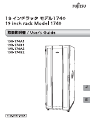
本書は、19 インチラック モデル 1740(以降、本製品)、およびオプション製品の取り扱い
の基本的なことがらについて説明しています。ご使用になる前に本書およびサーバ本体の
『ユーザーズガイド』をよくお読みになり、正しい取り扱いをされますようお願いいたし
ます。
2008 年 12 月
本製品のハイセイフティ用途での使用について
本製品は、一般事務用、パーソナル用、家庭用、通常の産業用等の一般的用途を想定して設計・製造されて
いるものであり、原子力施設における核反応制御、航空機自動飛行制御、航空交通管制、大量輸送システム
における運行制御、生命維持のための医療器具、兵器システムにおけるミサイル発射制御など、極めて高度
な安全性が要求され、仮に当該安全性が確保されない場合、直接生命・身体に対する重大な危険性を伴う用
途(以下「ハイセイフティ用途」という)に使用されるよう設計・製造されたものではございません。お客
様は、当該ハイセイフティ用途に要する安全性を確保する措置を施すことなく、本製品を使用しないでくだ
さい。ハイセイフティ用途に使用される場合は、弊社担当営業員までご相談ください。
当社のドキュメントには「外国為替および外国貿易管理法」に基づく特定技術が含まれていることがありま
す。特定技術が含まれている場合は、当該ドキュメントを輸出または非居住者に提供するとき、同法に基づ
く許可が必要となります。
本書の表記
■ 警告表示
本書ではいろいろな絵表示を使っています。これは製品を安全に正しくお使いいただき、
あなたや他の人々に加えられるおそれのある危害や損害を未然に防止するための目印とな
るものです。その表示と意味は次のようになっています。内容をよくご理解の上、お読み
ください。
2
警告
正しく使用しない場合、「死亡または重症を負うことがあり得る」こと
を示しています。
注意
正しく使用しない場合、「軽傷または中程度の傷害を負うことがあり得
る」こと、または「当該製品自身またはその他の使用者などの財産に
損害が生じる危険があり得る」ことを示しています。
また、危害や損害の内容がどのようなものかを示すために、上記の絵表示と同時に次の記
号を使用しています。
△で示した記号は、警告・注意を促す内容であることを告げるもので
す。記号の中やその脇には、具体的な警告内容が示されています。
で示した記号は、してはいけない行為(禁止行為)であることを告
げるものです。記号の中やその脇には、具体的な禁止内容が示されて
います。
●で示した記号は、必ず従っていただく内容であることを告げるもの
です。記号の中やその脇には、具体的な指示内容が示されています。
■ 本文中の記号
本文中に記載されている記号には、次のような意味があります。
記号
意味
お使いになる際の注意点や、してはいけないことを記述しています。
必ずお読みください。
ハードウェアやソフトウェアを正しく動作させるために必要なことが
書いてあります。必ずお読みください。
→
参照ページや参照マニュアルを示しています。
■ 製品の呼び方
本文中の製品名称を次のように略して表記します。
製品名称
19 インチラック モデル 1740
(19R-174A1、19R-174B1、19R-174A2、19R-174B2)
転倒防止用スタビライザ
本文中の表記
ラック、本製品
スタビライザ
■ リサイクルについて
本製品を廃却する場合、弊社担当営業員に相談してください。本製品は産業廃棄物として
処理する必要があります。
J
各製品名は、各社の商標、または登録商標です。
各製品は、各社の著作物です。
All Rights Reserved, Copyright© FUJITSU LIMITED 2008
3
目次
1
2
3
4
4
概要 . . . . . . . . . . . . . . . . . . . . . . . . . . . . . . . . . . . . . . . . . . . . . . . . .
5
1.1 ラインナップ . . . . . . . . . . . . . . . . . . . . . . . . . . . . . . . . . . . . . . . . . . . .
5
1.2 主な特長 . . . . . . . . . . . . . . . . . . . . . . . . . . . . . . . . . . . . . . . . . . . . . . . .
6
ラック設置・運用上のご注意 . . . . . . . . . . . . . . . . . . . . . . . . . . . .
7
2.1 設置場所に関する注意 . . . . . . . . . . . . . . . . . . . . . . . . . . . . . . . . . . . . .
7
2.2 搬入時の留意事項 . . . . . . . . . . . . . . . . . . . . . . . . . . . . . . . . . . . . . . . .
8
2.3 設置・運用時の留意事項 . . . . . . . . . . . . . . . . . . . . . . . . . . . . . . . . . . .
9
ラックの構成と設置 . . . . . . . . . . . . . . . . . . . . . . . . . . . . . . . . . . . .
12
3.1 構成 . . . . . . . . . . . . . . . . . . . . . . . . . . . . . . . . . . . . . . . . . . . . . . . . . . . .
12
3.2 フロントドアの開き方 . . . . . . . . . . . . . . . . . . . . . . . . . . . . . . . . . . . . .
14
3.3 リヤドアの開き方 . . . . . . . . . . . . . . . . . . . . . . . . . . . . . . . . . . . . . . . .
15
3.4 ラックの設置 . . . . . . . . . . . . . . . . . . . . . . . . . . . . . . . . . . . . . . . . . . . .
16
3.5 ラックの連結 . . . . . . . . . . . . . . . . . . . . . . . . . . . . . . . . . . . . . . . . . . . .
18
ラック設置後の取り扱いについて . . . . . . . . . . . . . . . . . . . . . . . . .
25
4.1 ケージナット取り付け / 取り外し手順 . . . . . . . . . . . . . . . . . . . . . . . .
25
4.2 扉回転軸位置の変更手順 . . . . . . . . . . . . . . . . . . . . . . . . . . . . . . . . . . .
29
4.3 汎用テーブル(固定式)の取り付け . . . . . . . . . . . . . . . . . . . . . . . . . .
47
4.4 汎用テーブル(可動式)の取り付け . . . . . . . . . . . . . . . . . . . . . . . . . .
55
4.5 ケーブルホルダの取り付け手順 . . . . . . . . . . . . . . . . . . . . . . . . . . . . .
64
4.6 ブランクパネルの取り付け手順 . . . . . . . . . . . . . . . . . . . . . . . . . . . . .
66
1
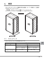
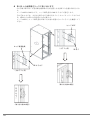
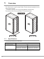
概要
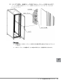
本ラックは 19 インチラック搭載型の富士通製品(オープン市場向け)を搭載す
るための 19 インチラックです。
・準拠規格:EIA19 インチラック規格(ユニバーサルピッチ)
19 インチラック モデル 1740 の外観イメージを以下に示します。
ࡕ࠺࡞㧝㧣㧠㧜
㧝㧥㧾㧙㧝㧣㧠㧭㧝
1.1
㧝㧥㧾㧙㧝㧣㧠㧭㧞
ラインナップ
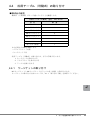
本ラックのラインナップは次の表のとおりです。
J
モデル 1740
収容ユニット数
型名
サイズ
(幅×奥行×高さ mm)
40U
転倒防止用スタビライザ付き
転倒防止用スタビライザ無し
基本ラック : 19R-174A1
増設ラック : 19R-174B1
基本ラック : 19R-174A2
増設ラック : 19R-174B2
700 × 1272 × 2000
700 × 1050 × 2000
1
概要
5
1.2
主な特長
■ 搭載可能装置
本ラックには以下の富士通製品を搭載できます。
(注 1)
・ PC サーバ「PRIMERGY」
・ UNIX サーバ「SPARC Enterprise」「PRIMEPOWER」
「S series」
・ ストレージシステム「ETERNUS」
・ 基幹 IA サーバ「PRIMEQUEST 510A」
(注 2)
・ ネットワーク製品(SR-S シリーズ等)
注 1) 詳細は弊社担当営業員までご相談ください。
注 2) 基幹 IA サーバ PRIMEQUEST 520A/520/420 は、本ラックには搭載できません。下
記のラックに搭載可能です。
・ MC-R7RC11/MC-R7RC21
・ MC-R7RC12/MC-R7RC22
・ MC-R8RC11/MC-R8RC21
・ MC-R8RC12/MC-R8RC22
■ 設置方法により添付品の選択が可能
設置方法に合わせて、転倒防止用スタビライザ添付の有無が選べます。
■ ラックの中心に装置を搭載
従来のスタンダードラックやグローバルラックは、正面から見て右寄りに装置を配置して
いましたが、本ラックでは装置搭載エリアをラックの中心に配置しました。これにより、
片側にケーブルが集中することなく、ケーブル配線が容易となります。
■ ケーブルホルダを標準搭載
ラック内部のケーブルルートにケーブルホルダを標準搭載しており、ケーブルマネージメ
ントが容易になります。
■ 冷却性能向上
前後扉の開口率を 80%とし、冷却性能を向上しました(従来のスタンダードラックやグ
ローバルラックは開口率 60%)。
■ 扉の回転軸が変更可能
本ラックの設置場所において、扉の回転軸の位置を変更することが可能です。
6
2
ラック設置・運用上のご注意
この章では、ラックの設置、搬入、運用上の注意事項について説明します。
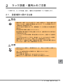
2.1
設置場所に関する注意
警告
・ 振動の激しい場所(200 ガルを超える)や傾いた場所など、不安定な場所に置
かないでください。機器の安定動作をさまたげたり、ラックが転倒するなどし
て重傷を負う可能性があります。
250 ガルを超える地震に対しては、搭載装置/ラックの固定などの地震対策が
必要です。
・ 床の強度が弱い場所に設置しないでください。
最大搭載時の最大重量は 1000Kg 程度になるため、強度が弱い床では床が抜け
る可能性があります。
・ ラックシステムの正常な稼動/保守を容易にするために、設置エリアを確保し
てください。
・ ラックの上または近くに「花びん・植木鉢・コップ」などの水の入った容器、
金属物を置かないでください。故障・火災・感電の原因となります。
・ 湿気・ほこり・油煙の多い場所、通気性の悪い場所、火気のある場所に置かな
いでください。故障・火災・感電の原因となります。
注意
・ 直射日光の当たる場所や、暖房器具の近くなど、高温になる場所には設置しな
いでください。
また、10 ℃未満の低温になる場所には、設置しないでください。
故障の原因になります。
・ ラックの開口部(通風孔など)をふさがないでください。
通風孔をふさぐと内部に熱がこもり故障や火災の原因となります。
J
2
ラック設置・運用上のご注意
7
2.2
搬入時の留意事項
本ラックまたは本体製品の、搬入時の留意事項を下記に示します。
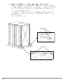
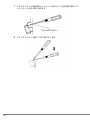
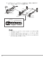
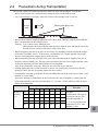
・ 本ラックを搬入の際は、搬入経路の間口が本ラックの寸法以上であることを事前に確認
してください。
・ 搬入経路に段差がある場合、渡板が必要な場合があります。
㧔ⵝ⟎㧕
ᷰ᧼㧔㋕᧼╬㧕
・ 本ラック込みの最大質量は 1000 kg 程度になる場合があるため、搬入経路に問題がない
ことを事前に確認してください。
例)搬入経路の床状態:
耐荷重はあるか、キャスターが床面にしずんだり、引っ掛かったりしない状態であ
ることを確認する。
・ 建物の上層階・下層階に装置を搬入する際、エレベーターが使用できること、またエレ
ベーターの積載重量が搬入する装置重量以上でも使用できることを事前に確認してくだ
さい。
・ 装置搬入時は、転倒防止のためラック高さ方向の半分よりも下を押してください。
本ラックに搭載する装置によっては、重心位置が高い場合があります。
また、側面からは押さないでください。転倒するおそれがあります。
・ 前扉の中央付近、吸気口部分を押すと扉が変形するおそれがありますので、扉の角を押
してください。
・ ラック搭載の本体製品を寒い場所から暖かい部屋へ搬入すると、製品内部が結露しま
す。
1時間当たりの温度上昇が 15 ℃を超えないように室温調整を行い、結露を発生させな
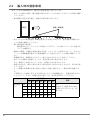
いようにしてください。結露の発生に関しては、次の表を参考にしてください。
室内温度
10
相対湿度
(%)
8
15
20
25
30
35
40
20
-7
-5
-3
1
5
9
13
40
-3
2
7
11
16
20
24
60
3
8
13
17
22
26
31
80
7
12
17
22
26
31
-
90
9
13
19
24
29
34
-
備考
例)
温度 25 ℃で湿度 60%の場合、
装置が 17 ℃以下のとき、結
露します。
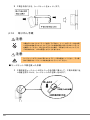
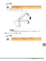
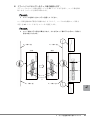
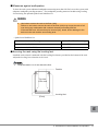
・ 本ラックに添付されている「鍵」は、紛失しないように管理を徹底してください。「鍵」
はラックに貼り付けられている場合(下図参照)と、添付品が入れられた箱に同梱され
ている場合があります。
㎛ਛ
- G[ENQUGU
㎛↪ⴼ
ࡈࡠࡦ࠻࠼ࠕ
䌛࠶ࠢߦ⾍ࠅઃߌࠄࠇߡࠆ႐ว䌝
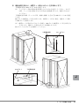
2.3
設置・運用時の留意事項
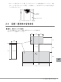
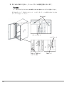
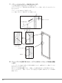
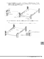
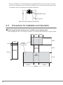
■ 通気、保守エリアの確保
ラックを設置するときは、放熱と保守用にスペースが必要です。
次のスペースを確保してください。
OO
OO
OO
OO
OO
OO
OO
ㅢ᳇ޔࠛࠕ
࠶ࠢ㕙ⷞ
࠶ࠢ೨㕙ⷞ
OO
࠶ࠢ೨㕙
OO
J
OO
OO
OO
2
ラック設置・運用上のご注意
9
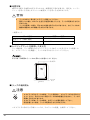
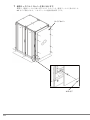
■ 地震対策
250 ガルを超える地震に対応するためには、耐震固定工事が必要です。固定は、レベリン
グフットを用いる方法とオプションの耐震キットを用いる方法があります。
警告
`
ラックはボルト等で床(スラブ)に固定してください。
固定しない場合、250 ガル を超える地震が発生したとき、ラックが転倒するおそれ
があります。
ラックが転倒した場合、死亡または重症を負うおそれがあります。またラック内の
機器や周囲のものが破損するおそれがあります。
・ 耐震キット
ラック型名
耐震キット型名
基本ラック(19R-174A2)
19R-17ST1
増設ラック(19R-174B2)
19R-17ST2
■ レべリングフットを使用した支え方
ラック搬入後、ラック底面にあるレベリングフットで本ラックを支えるように設置しま
す。レベリングフットを調整し、ラックが水平になるようにしてください。
キャスターは床面から 1 ~ 2mm 浮かした状態にしてください。
’
ࠠࡖࠬ࠲
ᧄ
㕙
ࡈࡠࡦ࠻
ࡌࡦࠣ
ࡈ࠶࠻
■ ラックの転倒防止
注意
・ スタビライザ付きラックの場合、ラック設置時に、スタビライザは必ず取り付
けてください。取り付けない状態でラック内部の装置を引き出すと、ラックが
転倒するおそれがあります。
・ スタビライザ無しラックの場合、必ずラックを固定設置して下さい。
固定設置しない場合、ラックが転倒するおそれがあります。
スタビライザの取り付け手順については、「3.4 ラックの設置」を参照してください。
10
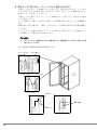
■ ブランクパネルの取り付け
注意
・ ブランクパネルを装置未搭載部に取り付けないと、排気が吸気面に回り込んで
装置の故障や寿命を短縮するおそれがあります。
装置を取り付けていない部分に、ブランクパネルを取り付けます。
ブランクパネルの取り付けの手順については、「4.6 ブランクパネルの取り付け手順」を参
照してください。
■ その他の留意事項
注意
・ ラックのフロントドア、リヤドアは取り外さないでください。扉は重量がある
ため、倒れたり、落下したりしてけがの原因となることがあります。
取り外す必要が生じた場合には、弊社担当保守員にご連絡ください。
J
・ ラック設置後にラックを移動する場合は、必ず弊社担当営業員または担当保守
員にご連絡ください。不用意に移動すると、ラックが損傷することがあります。
・ ラックに登ったり寄りかかったりしないでください。転倒などの事故のおそれ
があります。
2
ラック設置・運用上のご注意
11
ラックの構成と設置
3
この章では、本ラック(40U)の構成、設置、取り扱い手順、ラックの連結手順
などについて説明します。
構成
3.1
本ラックの仕様と付属品を次に示します。
スタビライザ付きラック
3.1.1
項目
仕様
品名
19 インチラック モデル 1740 基本ラック
19 インチラック モデル 1740 増設ラック
型名
19R-174A1
19R-174B1
外観
黒色塗装(前後扉パンチングメタル仕様)
収納
ユニット数
40U
サイズ
(WxDxH)
[mm]
700 x 1272(転倒防止用スタビライザ込み、ラック本体 1050)x 2000
搭載最大
質量
[kg]
ラック総質量 : 943kg (注 1)
搭載総質量 : 800kg(ラック本体除く)
ラック本体 : 143kg(転倒防止用スタビライ
ザ含む)
セキュリ
ティ
前後扉にキーロックあり ( ハンドルロックにはキー操作が必要です )
付属品
・ 前扉、後扉、サイドカバー(2 枚組)(ラッ
クに取付け済)
・ ラック扉用キー : 2 個
・ 転倒防止用スタビライザ : 1 枚(前用)
・ ケージナット / ネジ(ワッシャー組込済):
各 50 個
(工場搭載装置で使用した場合は、その残り
の数量のみ添付)
・ ケージナット工具
・ ブランクパネル : 1U × 3 枚、2U × 5 枚、3U
×3枚
・ ケーブルホルダ : 24 個(ラックに取付け済)
・ 取扱説明書
ラック総質量 : 910kg (注 1)
搭載総質量 : 800kg(ラック本体除く)
ラック本体 : 110kg(転倒防止用スタビライザ
含む)
・ 前扉、後扉 (ラックに取付け済)
(注 2)
・ ラック扉用キー : 2 個
・ 転倒防止用スタビライザ : 1 枚(前用)
・ 連結キット : 1 式
・ ケージナット / ネジ(ワッシャー組込済):
各 50 個
(工場搭載装置で使用した場合は、その残り
の数量のみ添付)
・ ケージナット工具
・ ブランクパネル : 1U × 3 枚、2U × 5 枚、3U
×3枚
・ ケーブルホルダ : 24 個(ラックに取付け済)
・ 取扱説明書
注 1) ラック総質量に基づくフロア荷重が設置場所(事務所など)の床強度(耐荷重)
の制限を超えないようにご注意ください。
注 2) 増設ラックにはサイドカバー(2 枚組)はありません。
`
12
基本ラックと増設ラック、増設ラックと増設ラックは連結可能です。ただしモデル 1640 /
1624 のラックやその他のシリーズのラックとは連結できません。
スタビライザ無しラック
3.1.2
項目
仕様
品名
19 インチラック モデル 1740 基本ラック
19 インチラック モデル 1740 増設ラック
型名
19R-174A2
19R-174B2
外観
黒色塗装 ( 前後扉パンチングメタル仕様 )
収納
ユニット数
40U
サイズ
(WxDxH)
[mm]
700 x 1050 x 2000
搭載最大
質量
[kg]
ラック総質量 : 935kg (注 1)
搭載総質量 : 800kg(ラック本体除く)
ラック本体 : 135kg
セキュリ
ティ
前後扉にキーロックあり(ハンドルロックにはキー操作が必要です)
付属品
・ 前扉、後扉、サイドカバー(2 枚組)
(ラックに取付け済)
・ ラック扉用キー : 2 個
・ ケージナット / ネジ(ワッシャー組込済):
各 50 個
(工場搭載装置で使用した場合は、その残り
の数量のみ添付)
・ ケージナット工具
・ ブランクパネル : 1U × 3 枚、2U × 5 枚、
3U × 3 枚
・ ケーブルホルダ : 24 個(ラックに取付け済)
・ 取扱説明書
ラック総質量 : 902kg (注 1)
搭載総質量 : 800kg(ラック本体除く)
ラック本体 : 102kg
・ 前扉、後扉 (ラックに取付け済)
(注 2)
・ ラック扉用キー : 2 個
・ 連結キット : 1 式
・ ケージナット / ネジ(ワッシャー組込済):
各 50 個
(工場搭載装置で使用した場合は、その残り
の数量のみ添付)
・ ケージナット工具
・ ブランクパネル : 1U × 3 枚、2U × 5 枚、
3U × 3 枚
・ ケーブルホルダ : 24 個(ラックに取付け済)
・ 取扱説明書
注 1) ラック総質量に基づくフロア荷重が設置場所 ( 事務所など ) の床強度 ( 耐荷重 ) の
制限を超えないようにご注意ください。
注 2) 増設ラックにはサイドカバー(2 枚組)は添付されていません。
`
基本ラックと増設ラック、増設ラックと増設ラックは連結可能です。モデル 1640 / 1624 の
ラックやその他のシリーズのラックとは連結できません。
J
3
ラックの構成と設置
13
3.2
フロントドアの開き方
1 扉用キーを回し、ラックハンドルを持ち上げ、手前に引きます。
’
注意
・ フロントドアを閉めるときは、搭載装置を完全に固定したあとに行ってください。
地震が発生した場合、装置が飛び出し破損するおそれがあります。
14
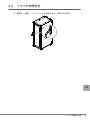
3.3
リヤドアの開き方
1 扉用キーを回し、ラックハンドルを持ち上げ、手前に引きます。
’
J
3
ラックの構成と設置
15
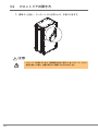
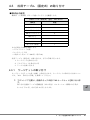
3.4
ラックの設置
スタビライザ付きラックの場合は、スタビライザを取り付けます。
スタビライザ無しラックの場合は、レベリングフットを使って固定するか、耐震キットを
取り付けて固定します。
3.4.1
スタビライザ付きラックの設置
ラックには前面側に取り付ける転倒防止スタビライザ ( 安定板 ) が基本で添付されていま
すので、図のように取り付けて下さい。
’
ขࠅઃߌ
警告
・ ラック設置時に、スタビライザは必ず取り付けてください。取り付けない状態
でラック内部の装置を引き出すと、ラックが転倒するおそれがあります。
16
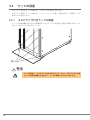
3.4.2
スタビライザ無しラックの設置
レベリングフットあるいは耐震キットを使用してラックを床に固定します。
■ レベリングフットを使用した固定
レベリングフット底面にあいている M20、深さ 17mm のネジ穴を使用して、床に固定しま
す。
■ 耐震キットを使用した固定
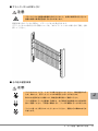
以下に耐震キットの取り付け手順を示します。
1 ラックの前後左右の面に、耐震キットを取り付けます。
`
耐震キットはオプション品です。
2 前面/側面の金具を 3 本のボルトで、背面の金具を 2 本のボルトでラッ
クに取り付けます。
3 耐震キットを床に固定します。
1. 前面と背面の金具は、2 本のボルトで床に固定します。
2. 側面のスタビライザは、3 本のボルトで床に固定します。
’
ᧄߩࡏ࡞࠻ߢ
࿕ቯ ೨㕙⢛㕙
ᧄߩࡏ࡞࠻ߢ
࿕ቯ 㕙
J
3
ラックの構成と設置
17
3.5
ラックの連結
ラックを増設する場合は、すでに設置してあるラック(基本ラックまたは増設ラック)に
連結します。
警告
・ ラックの連結を行う場合は、サーバ本体および周辺装置の電源を切り、電源
ケーブルをコンセントから取り外してください。
感電したり機器が故障するおそれがあります。
注意
・ ラックの連結を行う場合は、必ず 2 人以上で行ってください。
けがの原因となります。
・ ラック上部で行う作業の際、脚立の上に乗る場合があります。
落下にご注意ください。
・ ラックの連結を行うとき、ラックに足をのせないでください。
■ 構成品の確認
増設ラックに添付されている、連結キットの構成品(下表参照)がすべて揃っていること
を確認します。
品
名
数
量
上部連結金具
1
下部連結金具
2
連結用パッキン
2
M12 ボルト
4
上部連結用
M8 ボルト
4
下部連結用
また必要な工具類を準備します。
・プラスドライバ(2 番、3 番)
・六角ボルト用レンチ(M8 用:呼び 13、M12 用:呼び 19)
なお、高所での作業が必要ですので、脚立をご準備ください。
18
備考
以下にラックの連結方法を示します。(例:基本ラックの右側へ増設する場合)
1 既設ラックのサイドカバーを取り外します。
サイドカバーを固定している M6 ネジ 8 本を外して、サイドカバーを取り外しま
す。
`
ここで取り外した M6 ネジは、後で使用しますので紛失しないようにご注意くだ
さい。
’
ࠨࠗ࠼ࠞࡃ
㧹㧢ࡀࠫ
J
3
ラックの構成と設置
19
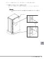
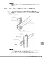
2 既設ラックの連結側耐震キットを取り外します。
連結側耐震キット(側面)のラックおよび建屋床面を固定しているネジまたはボル
トをすべて取り外し、耐震キット(側面)を取り外します。
また耐震キット(前面、背面)のラック側固定ボルトの内、連結側ボルトを各1本
取り外します。
`
ここで取り外した耐震キット(側面)およびボルトは、後で使用しますので紛失
しないようにご注意ください。
’
ㅪ⚿ࡏ࡞࠻
⠴㔡ࠠ࠶࠻ ⢛㕙 ⠴㔡ࠠ࠶࠻
㧔㕙㧕
⠴㔡ࠠ࠶࠻ ೨㕙 20
ᑪደᐥ㕙࿕ቯࡏ࡞࠻
ㅪ⚿ࡏ࡞࠻
࠶ࠢ࿕ቯࡏ࡞࠻
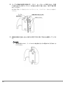
3 連結パッキンを貼り付けます。
連結パッキンの保護紙を剥がして連結面のフレームに、ラックの上部から貼り付け
ます。
ラック前側と背面側2ヶ所に貼り付けます。
’
ࡈࡓ
ࡈࡓ
ㅪ⚿ࡄ࠶ࠠࡦ
4 既設ラックと増設ラックの高さを合わせます。
既設ラックの横に増設ラックを並べ、増設ラックのレベルフットを調節し、既設
ラックと高さを合わせます。
J
3
ラックの構成と設置
21
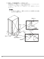
5 増設ラックに耐震キット(前面・側面・背面)を取り付けます。
増設ラック用耐震キット(前面・背面)および既設ラックから取り外した耐震キッ
ト(側面)を増設ラック取り付けます。ボルトは耐震キットに添付のものおよび既
設ラックから取り外したものを使用します。連結金具取付け後、本締めしますの
で、ここでの作業は仮留めとします。
なお、耐震キット(前面・背面)はラックとの固定部がそれぞれ3ヶ所あります
が、既設側ラックに最も近い側のそれぞれ1ヶ所は連結金具と共締めしますので、
後で取り付けます。
(次ページを参照ください)
’
ขઃߌࡏ࡞࠻
22
ขઃߌࡏ࡞࠻
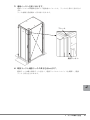
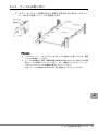
6 連結金具を取付け、耐震キット取付けボルトを本締めします。
上部連結金具を M12 ボルト 4 本で固定します。
注) トップカバー部の作業は高所作業となりますので注意してください。またそ
の際、ラックに足を乗せるなどの行為は大変危険ですので、絶対に行わない
でください。
下部連結金具2個(ラックの下部、前側と後側)をそれぞれ M8 ボルト 2 本で固定
します。
M8 ボルトは耐震キット用を共用します。耐震キットがない場合、連結キット添付
の M8 ボルトを使用します。
注) 耐震キットが取り付けられている場合、M8 ボルトは耐震キット用と共用とな
りますので、連結キット添付のボルトは余剰となります。
仮止めしていたボルトを本締めしてください。
’
ㇱㅪ⚿㊄ౕ
㧹㧝㧞ࡏ࡞࠻
㧹㧤ࡏ࡞࠻
ਅㇱㅪ⚿㊄ౕ
J
3
ラックの構成と設置
23
7 増設ラックにサイドカバーを取り付けます。
最後に、既設ラックから取り外したサイドカバーを、既設ラックから取り外した
M6 ネジで取付けます。これでラックの連結作業は終了です。
’
ࠨࠗ࠼ࠞࡃ
24
㧹㧢ࡀࠫ
ラック設置後の取り扱いについて
4
この章では、ラック設置後の取り扱いについて説明します。
4.1
ケージナット取り付け / 取り外し手順
4.1.1
取り付け手順
1 ケージナットをラック内側より取り付けます。ケージナットの一方の爪
を、ラックのケージナット取り付け穴に引っ掛けます。
図は下側に引っ掛けた場合をあらわしています。
’
2 ケージナット工具先端の爪をケージナット取り付け穴の手前から挿入し、
ケージナットのもう一方の爪に嵌合させます。
’
J
4
ラック設置後の取り扱いについて
25
3 工具を手前に引き、ケージナットをセットします。
’
4.1.2
取り外し手順
注意
工具あるいはマイナスドライバを押し下げる前に、ナットの爪とラック柱の間
に工具の先端あるいはマイナスドライバの先端が完全に押し込まれていること
を確認してください。押し込みが不十分な場合、工具あるいはマイナスドライ
バの先端が外れ、けがの原因となることがあります。
注意
ケージナットがラック内に落ちないようテープ等で養生してください。手で保
持する場合はケージナットの左右を持つようにしてください。
■ ケージナット工具を使った手順
1 工具先端をケージナットの爪とラック柱の間に挿入して、工具の先端に近
い位置を指でつかみ、ケージナットの爪を押し込みます。
’
26
注意
指定位置より先端をつかまないでください。押し込み時に指がラックに当たり、
ケガをする原因になります。
2 工具を押し下げて取り外します。
ケージナットを落とさないよう注意してください。
’
`
増設、移設作業時にも本工具が必要となりますので、大切に保管してください。
■ マイナスドライバを使った手順
注意
ケージナットがラック内に落ちないようテープ等で養生してください。手で保
持する場合はケージナットの左右を持つようにしてください。
J
4
ラック設置後の取り扱いについて
27
1 マイナスドライバの先端をケージナットの爪とラック柱の間に挿入して、
ケージナットの爪に押し込みます。
’
2 マイナスドライバを押し下げて取り外します。
’
28
扉回転軸位置の変更手順
4.2
扉の回転軸を工場出荷時の位置から変更します。工場出荷時の位置は、前扉は左軸、後扉
は右軸です。
取り付け済の部品を取り外し、位置を変えて再度取り付ける作業を多数行います。取り付
けや取り外しで部品の変形、破損、紛失が発生しないように十分注意して作業してくださ
い。
`
取り外した部品は必ず再使用します。余剰は発生しません。またラックに予備部品は添付
されていませんのでご注意願います。部品の取り外し、取り付けにある程度のカが必要な
場合があります。作業にあたってはご注意願います。
以下の作業には、プラスドライバ(2 番)やマイナスドライバなどの工具が必要です。
4.2.1
前扉の軸位置変更手順
1 ラックから扉を取り外します。
扉を開け、上下 2ヶ所にあるヒンジセットのそれぞれ下側のネジを緩め、下側ヒン
ジを下に下げてください。
`
ネジは緩めるだけでよく、取り外す必要はありません。
J
4
ラック設置後の取り扱いについて
29
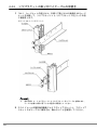
2 次に M5 六角ネジを外し、ストッパワイヤの固定を取り外します。
`
外したネジとワイヤは、後で使用しますので紛失しないようにご注意ください。
扉全体を持ち上げ、扉を取り外します。この時、扉とラックの隙間に指などを挟ま
ないように注意してください。
’
/ ⷺࡀࠫ
ࠬ࠻࠶ࡄࡢࠗࡗ
ࡅࡦࠫ࠶࠻
ਅࡅࡦࠫ࿕ቯࡀࠫ
㧔ਅ ࡩᚲ㧕
30
ਅࡅࡦࠫ
3 ラック側の金具類を取り外します。
M5 ネジを外し、上下 2ヶ所のヒンジ ASSY を取り外します。ヒンジ ASSY に固定
されているヒンジスペーサも同時に外れます。
M5 サラネジを外し、上中下 3ヶ所のロッド棒受金具を取り外します。
’
ࡅࡦࠫࠬࡍࠨ
ࡠ࠶࠼ฃ㊄ౕ
/ ࡀࠫ
ࡅࡦࠫ #55;
㧔ਅ ࡩᚲ㧕
/ ࠨࡀࠫ
㧔ਛਅ ࡩᚲ㧕
J
4
ラック設置後の取り扱いについて
31
4 取り外した金具類をラックに取り付けます。
2 の手順で取り外した金具類を標準取り付け位置と左右反転した位置に取り付けま
す。
ヒンジ ASSY は M5 ネジで、ロッド棒受金具は M5 サラネジで固定します。
それぞれのネジは、ネジ山を刻みながら締め付けていくセルフタッピングネジのた
め、締め付けの際にある程度の力が必要です。
ヒンジ ASSY とロッド棒受金具が取り付け後の状態になっていることを確認してく
ださい。
’
ࡅࡦࠫ #55;
ࡠ࠶࠼ฃ㊄ౕ
㧔ਅ ࡩᚲ㧕
/ ࡀࠫ
䴿ࠨࠗ࠼ࠞࡃ䳦䵀
/ ࠨࡀࠫ
㧔ਛਅ ࡩᚲ㧕
䴿ࠨࠗ࠼ࠞࡃ䳦䵀
㧔ขࠅઃߌᓟߩ⁁ᘒ㧕
32
㧔ขࠅઃߌᓟߩ⁁ᘒ㧕
5 扉からドアハンドル(ロッド棒付き)と富士通ロゴを取り外します。
上下にあるロッド棒サポータにマイナスドライバを真横から差し込み、サポータを
すべて取り外します。
`
上側のロッド棒が作業者側へ倒れてくる可能性がありますので注意してくださ
い。
ドアハンドル上下にある M5 ネジを外します。
ドアハンドルとロッド棒を同時に扉から取り外します。
M4 ネジを外し、富士通ロゴを取り外します。M4 ネジを外すときに富士通ロゴが
落下する可能性がありますので、手を添えて外してください。
’
ࡠ࠶࠼
ን჻ㅢࡠࠧ
ࡑࠗ࠽ࠬ
࠼ࠗࡃ
ࡠ࠶࠼ࠨࡐ࠲
㧔ਅ ࡩᚲ㧕
/ ࡀࠫ
࠼ࠕࡂࡦ࠼࡞
ᚺ
࠼ࠕࡂࡦ࠼࡞
J
/ ࡀࠫ
ࡠ࠶࠼
4
ラック設置後の取り扱いについて
33
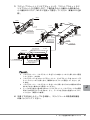
6 ドアハンドルに付いているロッド棒を組み替えます。
ドアハンドルとロット棒を固定している M3 バインドネジを外し、ロッド棒を取り
外します(スペーサも同時に外れます)。
`
スペーサを無くさないように注意してください。
ロッド棒先端の曲げ部分が左側に向くようにして、ハンドルの右側にロッド棒上
(短)を M3 バインドネジとスペーサで固定します。
`
ロッド棒は上下で長さが異なります。上になるロッド棒が下になるロッド棒より
長さが短くなります。
’
ࡠ࠶࠼ ⍴ ࡠ࠶࠼ ⍴ 㧔ಽ⸃㧕
㧔⚵┙㧕
/ ࡃࠗࡦ࠼ࡀ
ࠫ
ࠬࡍࠨ
34
ࡠ࠶࠼ਅ 㐳 ࡠ࠶࠼ਅ 㐳 7 ドアハンドルおよびロッド棒を取り付けます。
この作業を開始する前に扉の上下を反転します。
ドアハンドルとロッド棒の組立品を扉の表からロッド棒上(短)が上になるように
差し込みます。
ドアハンドルを M5 ネジにて固定します。
ロッド棒上下をロッド棒サポータにて固定します。
’
࠼ࠕࡂࡦ࠼࡞
ᚺ
ࡠ࠶࠼ ⍴ ࡠ࠶࠼ਅ 㐳 ࡠ࠶࠼
ࡠ࠶࠼ࠨࡐ࠲㧔ขࠅઃߌᓟߩ⁁ᘒ㧕
㧔ਅ ࡩᚲ㧕
/ ࡀࠫ
J
࠼ࠕࡂࡦ࠼࡞
4
ラック設置後の取り扱いについて
35
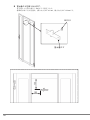
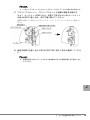
8 富士通ロゴを取り付けます。
富士通ロゴを扉の裏から M4 ネジで固定します。
標準的な取り付け位置は、横方向寸法が 103 ㎜、縦方向寸法が 122 ㎜です。
’
/ ࡀࠫ
ን჻ㅢࡠࠧ
36
9 ストッパワイヤを扉に取り付け、上下 2ヶ所のヒンジセットの位置を調整
します。
ストッパワイヤを M5 六角ネジで扉に仮留めします。本締めはラック側にワイヤを
取り付けるときに行います。
次にヒンジの位置を調整します。上側ヒンジは扉の取り外し工程で緩んだままと
なっていますので、下側いっぱいに下げて固定ネジを締め、傾かないように本締め
固定します。
`
上側ヒンジを固定ネジで締め付ける際、下側ヒンジに突き当てるように締め付け
てください。
次に下側ヒンジの固定ネジを緩め、ヒンジを下側いっぱいに移動します。
下側ヒンジの固定ネジは扉をラックに取り付けた後に本締めしますので、ここでは
締め付けません。
’
ࠬ࠻࠶ࡄࡢࠗࡗ
/ ⷺࡀࠫ
ࡅࡦࠫ
ᚺࠃࠅࠆ
J
ࡅࡦࠫ࿕ቯࡀࠫ
ᧄ✦࿕ቯ
ਅࡅࡦࠫ
ࡅࡦࠫ࠶࠻
㧔ਅ ࡩᚲ㧕
ᚺⵣࠃࠅࠆ
4
ラック設置後の取り扱いについて
37
10 扉をラックに取り付け、ストッパワイヤを取り付けます。
上側ヒンジの穴にヒンジ ASSY のピンを差し込み、扉を取り付けます。ヒンジは上
下 2ヶ所ありますので同時に差し込むようにします。扉とラックの隙聞に指などを
挟まないように注意してください。
下側ヒンジを上側にスライドし、ヒンジ ASSY のピンに差し込み、固定ネジを締め
つけて固定します。ヒンジ ASSY と上側ヒンジおよび下側ヒンジの隙間が同じであ
ることを目視確認します。
隙間に違いがある場合は、下側ヒンジまたはヒンジ ASSY の取り付け位置を調整し
てください。
ストッパワイヤを M5 六角ネジでフレームに取り付け固定します。また仮留めして
いた扉側のワイヤ固定ネジを本締めします。
`
ストッパワイヤを固定するネジの締め付けは、扉を開け、ワイヤが引っ張られた
状態で行ってください。
’
/ ⷺࡀࠫ
ࡅࡦࠫ #55;
ࠬ࠻࠶ࡄࡢࠗࡗ
ࡅࡦࠫ #55; ߩࡇࡦ
ࡅࡦࠫ
ਅࡅࡦࠫ
㓗㑆ߩ⏕
㧔ਅ ࠞᚲ㧕
以上で前扉の回転軸位置変更作業は終了です。
38
4.2.2
後扉の軸位置変更手順
1 ラックから扉を取り外します。
扉を開け、上下 2ヶ所にあるヒンジセットのそれぞれ下側のネジを緩め、下側ヒン
ジを下に下げてください。
`
ネジは緩めるだけでよく、取り外す必要はありません。
2 次に M5 六角ネジを外し、ストッパワイヤの固定を取り外します。
`
外したネジとワイヤは、後で使用しますので紛失しないようにご注意ください。
扉全体を持ち上げ、扉を取り外します。この時、扉とラックの隙間に指などを挟ま
ないように注意してください。
’
ࠬ࠻࠶ࡄࡢࠗࡗ
/ ⷺࡀࠫ
ࡅࡦࠫ࠶࠻
J
ਅࡅࡦࠫ࿕ቯࡀࠫ
ਅࡅࡦࠫ
㧔ਅ ࠞᚲ㧕
4
ラック設置後の取り扱いについて
39
3 ラック側の金具類を取り外します。
M5 ネジを外し、上下 2ヶ所のヒンジ ASSY を取り外します。ヒンジ ASSY に固定
されているヒンジスペーサも同時に外れます。
M5 サラネジを外し、上中下 3ヶ所のロッド棒受金具を取り外します。
’
ࡅࡦࠫࠬࡍࠨ
ࡅࡦࠫ #55;
/ ࡀࠫ
㧔ਅ ▎ᚲ㧕
ࡠ࠶࠼ฃ㊄ౕ
40
/ ࠨࡀࠫ
㧔ਛਅ ࡩᚲ㧕
4 取り外した金具類をラックに取り付けます。
手順 3 で取り外した金具類を標準取り付け位置と左右反転した位置に取り付けま
す。
ヒンジ ASSY は M5 ネジで、ロッド棒受金具は M5 サラネジで固定します。
それぞれのネジは、ネジ山を刻みながら締め付けていくセルフタッピングネジのた
め、締め付けの際はある程度の力が必要です。
ヒンジ ASSY とロッド棒受金具が取り付け後の状態になっているか確認してくださ
い。
’
ࡅࡦࠫ #55;
/ ࡀࠫ
㧔ਅ ࠞᚲ㧕
ࡠ࠶࠻ฃ㊄ౕ
/ ࠨࡀࠫ
㧔ਛਅ ࡩᚲ㧕
㧔ขࠅઃߌᓟߩ⁁ᘒ㧕
J
㧔ขࠅઃߌᓟߩ⁁ᘒ㧕
4
ラック設置後の取り扱いについて
41
5 扉からドアハンドル(ロッド棒付き)を取り外します。
上下にあるロッド棒サポータにマイナスドライバを真横から差し込み、サポータを
すべて取り外します。
`
上側のロッド棒が作業者側へ倒れてくる可能性がありますので注意してくださ
い。
ドアハンドル上下にある M5 ネジを外します。
ドアハンドルとロッド棒を同時に扉から取り外します。
’
ࡠ࠶࠻
ࡠ࠶࠼ࠨࡐ࠲
ࡑࠗ࠽ࠬ
㧔ਅ ࡩᚲ㧕 ࠼ࠗࡃ
࠼ࠕࡂࡦ࠼࡞
࠼ࠕࡂࡦ࠼࡞
ᚺ
/ ࡀࠫ
42
ࡠ࠶࠼
6 ドアハンドルに付いているロッド棒を組替えます。
ドアハンドルとロッド棒を固定している M3 バインドネジを外し、ロッド棒を取り
外します(スペーサも同時に外れます)
。
`
スペーサを無くさないように注意してください。
ロッド棒先端の曲げ部分が右側に向くようにして、ハンドルの左側にロッド棒上
(短)を M3 バインドネジとスペーサで固定します。
`
ロッド棒は上下で長さが異なります。上になるロッド棒が下になるロッド棒より
長さは短くなります。
’
ࡠ࠶࠼ ⍴ ࡠ࠶࠼ ⍴ ಽ⸃ ⚵┙
ࠬࡍࠨ
/ ࡃࠗࡦ࠼ࡀ
ࠫ
ࡠ࠶࠼ਅ 㐳 ࡠ࠶࠼ਅ 㐳 J
4
ラック設置後の取り扱いについて
43
7 ドアハンドルおよびロッド棒を取り付けます。
この作業を開始する前に扉の上下を反転します。
ドアハンドルとロッド棒の組立品を扉の表からロッド棒上(短)が上になるように
差し込みます。
ドアハンドルを M5 ネジで固定します。
ロッド棒上下をロッド棒サポータで固定します。
’
ᚺ
࠼ࠕࡂࡦ࠼࡞
ࡠ࠶࠼ ⍴ ࡠ࠶࠼ਅ 㐳 ࡠ࠶࠼ ⍴ 㧔ขࠅઃߌᓟߩ⁁ᘒ㧕 ࡠ࠶࠼ࠨࡐ࠲
㧔ਅ ࠞᚲ㧕
࠼ࠕࡂࡦ࠼࡞
/ ࡀࠫ
8 ストッパワイヤを扉に取り付け、上下 2ヶ所のヒンジセットの位置を調整
します。
ストッパワイヤを M5 六角ネジで扉に仮留めします。本締めはラック側にワイヤを
取り付けるときに行います。
次にヒンジの位置を調整します。上側ヒンジは扉の取り外し工程で緩んだままと
なっていますので、下側いっぱいに下げて固定ネジを締めて傾かないように本締め
固定します。
44
`
上側ヒンジを固定ネジで締め付ける際、下側ヒンジに突き当てるように締め付け
てください。
次に下側ヒンジの固定ネジを緩め、ヒンジを下側いっぱいに移動します。
下側ヒンジの固定ネジは扉をラックに取り付けた後に本締めしますので、ここでは
締めつけません。
’
/ ⷺࡀࠫ
ࠬ࠻࠶ࡄࡢࠗࡗ
ࡅࡦࠫ
ᚺࠃࠅࠆ
ࡅࡦࠫ࿕ቯࡀࠫ
ᧄ✦࿕ቯ
ਅࡅࡦࠫ ࡅࡦࠫ࠶࠻
㧔ਅ ࠞᚲ㧕
ᚺⵣࠃࠅࠆ
J
4
ラック設置後の取り扱いについて
45
9 扉をラックに取り付け、ストッパワイヤを取り付けます。
上側ヒンジの穴にヒンジ ASSY のピンを差し込み、扉を取り付けます。ヒンジは上
下 2ヶ所ありますので同時に差し込むようにします。扉とラックの隙聞に指などを
挟まないように注意してください。
下側ヒンジを上側にスライドし、ヒンジ ASSY のピンに差し込み、固定ネジを締め
つけて固定します。
ヒンジ ASSY と上側ヒンジおよび下側ヒンジの隙間が同じであることを目視確認し
ます。
隙間に違いがある場合は、下側ヒンジまたはヒンジ ASSY の取り付け位置を調整し
てください。
ストッパワイヤを M5 六角ネジでフレームに取り付け固定します。また仮留めして
いた扉側のワイヤ固定ネジを本締めします。
`
ストッパワイヤを固定するネジの締め付けは、扉を開けワイヤが引っ張られた状
態で行ってください。
以上で後扉の回転軸位置変更作業は終了です。
’
ࠬ࠻࠶ࡄࡢࠗࡗ
/ ⷺࡀࠫ
ࡅࡦࠫ #55; ߩࡇࡦ
ࡅࡦࠫ #55;
㧔ਅ ࡩᚲ㧕
ࡅࡦࠫ
㓗㑆ߩ⏕
46
ਅࡅࡦࠫ
汎用テーブル(固定式)の取り付け
4.3
■ 構成品の確認
構成品(下表参照)がすべて揃っていることを確認します。
汎用テーブル ( 固定式 ) 型名:19R-16TR1
構成品
数量
テーブル
1
リヤブラケット L
1
リヤブラケット R
1
M6 ケージナット
8
M6 ボルト
4
M6 ネジ
8
ベルト
2
取り付け手順書
1
また必要な工具類を準備します。
・プラスドライバ(3 番)
・ケージナット工具
・六角ボルト用レンチ(M6 用:呼び 10)
汎用テーブル(固定式)の取り付けは、以下の手順で行います。
1. ケージナットを取り付ける
2. リヤブラケットを取り付ける
3. テーブルを取り付ける
4.3.1
ケージナットの取り付け
ケージナットをラックの柱(前後)に取り付けます。ケージナットの取り付け方法につい
ては、「4.1.1 取り付け手順」を参照してください。
1 フロントドアを開け、前側のラックの柱に M6 ケージナットを取り付けま
す。
取り付け位置はテーブル搭載位置(1U の高さ)のロケーション線間にある角穴
3ヶの上下 2ヶ所、左右合計 4ヶ所となります。
4
ラック設置後の取り扱いについて
J
47
2 リヤドアを開け、後側のラックの柱に M6 ケージナットを取り付けます。
取り付け位置はテーブル搭載位置(1U の高さ)のロケーション線間にある角穴
3ヶの上下 2ヶ所、左右合計 4ヶ所となります。
48
`
4.3.2
前後左右にて M6 ケージナットの取り付け位置が高さ方向でずれないようにして
ください。
リヤブラケットの取り付けとテーブルの仮置き
1 「4.3.1 ケージナットの取り付け」手順 2 で取り付けた後側の M6 ケージ
ナットを利用して、リヤブラケット R とリヤブラケット L をラックの柱
に仮固定します。
固定には M6 ネジを使用します。
J
・次の手順 2 で、リヤブラケット L とリヤブラケット R にテーブルを載せます。
テーブルを載せた際に落下しない程度に仮固定してください。
・リヤブラケット L、リヤブラケット R の取り付け向きに注意してください。
4
ラック設置後の取り扱いについて
49
2 テーブル前面の仮置き用曲げを、「4.3.1 ケージナットの取り付け」手順
2 で取り付けた M6 ケージナットの直上の角穴に差し込み、角穴下面に載
せてください。
後ろ側は手順 1 にて取り付けたリヤブラケット L、リヤブラケット R の上に載せて
ください。
3 仮置き用曲げを差し込んだ角穴が左右で同じ高さであるか確認してくださ
い。
`
50
仮置き状態ですので、テーブルの上に物を載せるなどの荷重がかかる行為はしな
いでください。
4.3.3
テーブルの取り付け
1 「4.3.1 ケージナットの取り付け」手順 2 で取り付けた M6 ケージナット
に、M6 ネジを使ってテーブルを固定します。
`
`
リヤブラケット L、リヤブラケット R がテーブルを載せても落下しないか、確認
してから作業をしてください。
テーブルを仮置きする際、前側は仮置き用曲げが角穴に対して十分差し込まれ確
実にテーブルが載るようにしてください。また、後側はリヤブラケット L、リヤ
ブラケット R にテーブルが確実に載るようにしてください。
なお、テーブルを固定するまでは支える手を離さないようにしてください。
J
4
ラック設置後の取り扱いについて
51
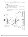
2 リヤブラケット L、リヤブラケット R の後ろより1番目と3番目のネジ
穴に、M6 ボルトを使ってテーブルを固定します。
䊁䊷䊑䊦
䌍䋶䊗䊦䊃
䌍䋶䊈䉳
㪙
㪞
䊁䊷䊑䊦
㪙
㪙
䊥䊟䊑䊤䉬䉾䊃䌒
㪘
㪚
㪞
㪘
䊤䉾䉪䈱ᩇ
㪚
䊥䊟䊑䊤䉬䉾䊃䌒
䊤䉾䉪䈱ᩇ
㪘
㪚
䊥䊟䊑䊤䉬䉾䊃䌌
䊥䊟䊑䊤䉬䉾䊃㪩
࿕ቯ䈮↪䈜䉎䊥䊟䊑䊤䉬䉾䊃㪩䈱䊈䉳ⓣ
䊁䊷䊑䊦
㶎䇭䊥䊟䊑䊤䉬䉾䊃㪣䉅ห䈛⟎
ᓟ䉋䉍䋱⇟⋡䈱䊈䉳ⓣ
ᓟ䉋䉍䋳⇟⋡䈱䊈䉳ⓣ
ᢿ㕙㪞㪄㪞
`
`
`
52
リヤブラケット L、リヤブラケット R をラックの柱にしっかりと押し付けて固定
してください。(A 方向)
リヤブラケット L、リヤブラケット R をテーブルにしっかりと押し付け、隙間が
ないようにして固定してください。(B、C 方向)
リヤブラケット L、リヤブラケット R をしっかり押し付けられない場合は※印の
M6 ネジを少し緩めてから固定してください。
3 M6 ネジを本締めして、「4.3.2 リヤブラケットの取り付けとテーブルの
仮置き」手順 1 にて仮固定していたリヤブラケット L、リヤブラケット R
をラックの柱に固定してください。
4 すべての M6 ネジ、M6 ボルトが締められていることを確認してくださ
い。
テーブルが下部の U スペース搭載を侵していないことを確認してください。
J
4
ラック設置後の取り扱いについて
53
5 必要に応じてラックの柱に固定している M6 ネジを緩め、再調整をしてく
ださい。
54
4.4
汎用テーブル(可動式)の取り付け
■ 構成品の確認
構成品(下表参照)がすべて揃っていることを確認します。
汎用テーブル ( 可動式 ) 型名:19R-16TR2
品
名
数
量
テーブル
1
リヤブラケット L
1
リヤブラケット R
1
M6 ケージナット
8
M5 ケージナット
2
M6 ネジ
12
ベルト
2
取り付け手順書
1
また必要な工具類を準備します。
・プラスドライバ(3 番)
・ケージナット工具
汎用テーブル(可動式)の取り付けは、以下の手順で行います。
1. ケージナットを取り付ける
2. リヤブラケットを取り付ける
3. テーブルを取り付ける
4.4.1
ケージナットの取り付け
M5 ケージナットと M6 ケージナットをラックの柱(前後)に取り付けます。
ケージナットの取り付け方法については、
「4.1.1 取り付け手順」を参照してください。
J
4
ラック設置後の取り扱いについて
55
1 フロントドアを開け、前側のラックの柱に M6 ケージナットを取り付けま
す。
M5 ケージナットの取り付け位置はテーブル搭載位置(1U の高さ)のロケーション
線間にある角穴 3ヶの真ん中 1ヶ所、左右合計 2ヶ所となります。
M6 ケージナットの取り付け位置はテーブル搭載位置(1U の高さ)のロケーション
線間にある角穴 3ヶの上下 2ヶ所、左右合計 4ヶ所となります。
56
2 リヤドアを開け、後側のラックの柱に M6 ケージナットを取り付けます。
ラックの柱側の位置はロケーション線間にある角穴 3ヶの上下 2ヶ所、左右合計
4ヶ所となります。
`
`
前後左右にて M6 ケージナットの取り付け位置が高さ方向でずれないようにして
ください。
M5 ケージナットは前側のラックの柱のみ取り付け、後側は取り付けません。
J
4
ラック設置後の取り扱いについて
57
4.4.2
リヤブラケットの取り付けとテーブルの仮置き
1 「4.4.1 ケージナットの取り付け」手順 2 で取り付けた後側の M6 ケージ
ナットを利用して、リヤブラケット L と リヤブラケット R をラックの柱
に仮固定します。
固定には M6 ネジを使用します。
`
次の手順 2 で、リヤブラケット L とリヤブラケット R にテーブルを載せます。
テーブルを載せた際に落下しない程度に仮固定してください。
2 スライドレールの簡易保持機能によりフロントブラケット L、フロントブ
ラケット R がテーブルに保持され、動かないことを確認してください。
58
`
フロントブラケット L とフロントブラケット R は、
テーブルに組み込み済みです。
3 フロントブラケット L、フロントブラケット R 前面の仮置き用曲げを、
「4.4.1 ケージナットの取り付け」手順 2 で取り付けた M6 ケージナット
の直上の角穴に差し込み、角穴下面に載せてください。
後側は手順 1 にて取り付けたリヤブラケット L、リヤブラケット R の上に載せてく
ださい。
4 仮置き用曲げを差し込んだ角穴が左右で同じ高さであるか確認してくださ
い。
`
仮置き状態ですのでテーブルの上に物を載せるなどの荷重が掛かる行為はしない
でください。
J
4
ラック設置後の取り扱いについて
59
4.4.3
テーブルの取り付け
1 「4.4.1 ケージナットの取り付け」手順 2 で取り付けた M6 ケージナット
に、M6 ネジを使ってテーブルを固定します。
䊥䊟䊑䊤䉬䉾䊃䌌
䊥䊟䊑䊤䉬䉾䊃䌒
䊐䊨䊮䊃䊑䊤䉬䉾䊃䌌
䌍䋶䉬䊷䉳䊅䉾䊃
⟎䈐↪ᦛ䈕
䊐䊨䊮䊃䊑䊤䉬䉾䊃䌌
䊐䊨䊮䊃䊑䊤䉬䉾䊃䌒
䌍䋶䊈䉳
`
`
`
`
`
`
䊁䊷䊑䊦
スライドレールは通常収納状態(水平にした状態)で飛び出し防止の簡易保持機
能が働きますが、テーブルの後側を下向きにした場合、簡易保持機構が外れスラ
イドレールが飛び出す可能性がありますのでご注意ください。
テーブル取り付け作業は後側が下向きにならないように作業をしてください。
スライドレールの簡易保持機能によりフロントブラケット L、フロントブラケッ
ト R がテーブルに保持され動かないことを確認してから作業をしてください。
スライドレール、フロントブラケット L、フロントブラケット R はテーブルに組
み込み済です。
リヤブラケット L、リヤブラケット R がテーブルを載せても落下しないか、確認
を行ってから作業をしてください。
テーブルを仮置きする際、前側は仮置き用曲げが角穴に対して十分差し込まれ確
実に載るように、後側はリヤブラケット L、リヤブラケット R に確実に載るよう
にしてください。
なお、テーブルを固定するまでは支える手を離さないようにしてください。
2 テーブルを約 185mm(リヤブラケット L、リヤブラケット R の固定用ネ
ジ穴が見えるようになるまで)引き出してください。
スライドレールの簡易保持機能により、引き出しの際は若干力が必要となります。
60
3 フロントブラケット L にリヤブラケット L を、フロントブラケット R に
リヤブラケット R を固定します。下側の後ろから2番目と上側の後ろか
ら2番目のネジ穴に、M6 ネジを使って固定してください(断面 G-G を参
照)。
䌍䋶䊈䉳
䌍䋶䊈䉳
㪙
㪞
䊁䊷䊑䊦
䊁䊷䊑䊦
䊥䊟䊑䊤䉬䉾䊃䌒
㪙
䊐䊨䊮䊃䊑䊤䉬䉾䊃䌒
㪘
㪚
䊐䊨䊮䊃䊑䊤䉬䉾䊃䌌
㪞
䊥䊟䊑䊤䉬䉾䊃䌒
㪘
䊤䉾䉪䈱ᩇ
㪙
䊤䉾䉪䈱ᩇ
䊐䊨䊮䊃䊑䊤䉬䉾䊃䌒
㪚
㪘
䊥䊟䊑䊤䉬䉾䊃䌌
㪚
䊐䊨䊮䊃䊑䊤䉬䉾䊃䌒
䊥䊟䊑䊤䉬䉾䊃㪩
䊁䊷䊑䊦
࿕ቯ䈮↪䈜䉎䊥䊟䊑䊤䉬䉾䊃㪩䈱䊈䉳ⓣ
㶎䇭䊥䊟䊑䊤䉬䉾䊃㪣䉅ห䈛⟎
䈱ᓟ䉋䉍䋲⇟⋡䈱䊈䉳ⓣ
䊁䊷䊑䊦⚊ᤨᓟ㕙⟎
ਅ䈱ᓟ䉋䉍䋲⇟⋡䈱䊈䉳ⓣ
䊁䊷䊑䊦ᒁ䈐䈚㊂⚂㪈㪏㪌㫄㫄
ᢿ㕙㩷㪞㪄㪞
`
`
`
`
リヤブラケット L、リヤブラケット R をラックの柱にしっかりと押し付けて固定
してください。(A 方向)
リヤブラケット L をフロントブラケット L に、リヤブラケット R をフロントブラ
ケット R にしっかりと押し付け、隙間がないようにして固定してください。(B、
C 方向)
リヤブラケット L、リヤブラケット R をしっかり押し付けられない場合は※印の
M6 ネジを少し緩めてから固定してください。
テーブルの引き出し量は約 185mm(リヤブラケット L、リヤブラケット R の固定
用ネジ穴が見えるようになるまで)とし、テーブルを引き出し過ぎないようにし
てください(断面 G-G 参照)。
J
4 手順 2 で引き出したテーブルを収納し、スライドレールの簡易保持機能
が働くようにしてください。
4
ラック設置後の取り扱いについて
61
5 M6 ネジを本締めして、「4.4.2 リヤブラケットの取り付け」手順 1 にて
仮固定していたリヤブラケット L、リヤブラケット R をラックの柱に固定
します。
6 すべての M6 ネジが締められていることを確認してください。
パネルファスナーを締め、テーブルを固定してください。
テーブルが下部の U スペース搭載を侵していないことを確認してください。
62
7 必要に応じてラックの柱に固定している M6 ネジを緩め、再調整をしてく
ださい。
J
4
ラック設置後の取り扱いについて
63
4.5
ケーブルホルダの取り付け手順
ケーブルホルダ(19R-17CM1)(前)およびケーブルホルダ(19R-17CM2)(後)を取り付
けます。
■ 構成品の確認
構成品(下表参照)がすべて揃っていることを確認します。
品
名
型
構成品および数量
19R-17CM1
ケーブルホルダ ( 前 ) × 1、M5 ネジ× 1
ケーブルホルダ ( 後 )
19R-17CM2
ケーブルホルダ ( 後 ) × 1、M5 ネジ× 1
また必要な工具類を準備します。
・プラスドライバ(2 番)
64
名
ケーブルホルダ ( 前 )
4.5.1
ケーブルホルダの取り付け
1 付属の M5 ネジを使用し、ケーブルホルダ(前)または(後)をフレーム
の取り付けたい位置の穴にプラスドライバで固定します。ネジは、ネジ山
を刻みながら締め付けていくセルフタッピングネジのため、締め付けの際
はある程度の力が必要です。
’
ࡈࡓ
㧔೨㕙㧕
㧹㧡ࡀࠫ
+࠼ࠗࡃ
ࠤࡉ࡞ࡎ࡞࠳(೨)
㧹㧡ࡀࠫ
ࡈࡓ
㧔⢛㕙㧕
+࠼ࠗࡃ
ࠤࡉ࡞ࡎ࡞࠳(ᓟ)
J
4
ラック設置後の取り扱いについて
65
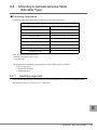
4.6
ブランクパネルの取り付け手順
4.6.1
構成品の確認
構成品(下表参照)がすべて揃っていることを確認します。
品
名
型
名
構成品および数量
1U ブランクパネル
19R-16BP1
ブランクパネル 1U 用× 1、M6 ケージナット×
2、M6 ネジ× 2
2U ブランクパネル
19R-16BP2
ブランクパネル 2U 用× 1、M6 ケージナット×
4、M6 ネジ× 4
3U ブランクパネル
19R-16BP3
ブランクパネル 3U 用× 1、M6 ケージナット×
4、M6 ネジ× 4
また必要な工具類を準備します。
・プラスドライバ(3 番)
・ケージナット工具
4.6.2
ブランクパネルの取り付け
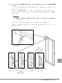
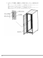
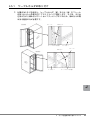
1 ケージナットをラックの柱(前側、左右 2 本)に裏面側から取り付けま
す。
ラックの柱は 1U の高さに対し、3 個の正方形の穴があります。ブランクパネルの
大きさに応じ、下記の位置にケージナットを取り付けます。
・ 1U 用の場合:中央の穴、左右 2ヶ所
・ 2U 用の場合:1U 目の中央と 2U 目の中央、左右合計 4ヶ所
・ 3U 用の場合:1U 目の中央と 3U 目の中央、左右合計 4ヶ所
2 ブランクパネルを M6 ネジで固定します。
手順 1 で取り付けたケージナット位置に対応する場所に穴があいています。ここに
ネジを使ってブランクパネルを固定します。
’
66
`
図は 1U / 2U / 3U 用をまとめて表示していますが、実際の取り付けは空きスペー
スに応じて、適切なサイズを選択し、取り付けてください。
J
4
ラック設置後の取り扱いについて
67
68
Before Reading This Manual
Thank you for your purchasing the 19-inch rack. This manual provides basic information on
handling the 19-inch rack Model 1740 ("this product") and optional products.
Before using this product, read this manual and the "User's Guide" supplied with the server to ensure
the correct use of this product.
December 2008
For Your Safety
This manual contains important information, required to operate this product safely.
Thoroughly review the information in this manual before using this product. Especially note the points under "Safety",
and only operate this product with a complete understanding of the material provided.
This manual should be kept in an easy-to-access location for quick reference when using this product.
High Safety
The Products are designed, developed and manufactured as contemplated or general use, including without limitation,
general office use, personal use, household use, and ordinary industrial use, but are not designed, developed and
manufactured as contemplated for use accompanying fatal risks or dangers that, unless extremely high safety is secured,
could lead directly to death, personal injury, severe physical damage, or other loss (hereinafter "High Safety Required
Use"), including without limitation, nuclear reaction control in nuclear facility, aircraft flight control, air traffic control,
mass transport control, medical life support system, missile launch control in weapon system. You shall not use this
Product without securing the sufficient safety required for the High Safety Required Use. If you wish to use this Product
for High Safety Required Use, please consult with our sales representatives in charge before such use.
Remarks
Warning Descriptions
Various symbols are used throughout this manual. These are provided to emphasize important points
for your safety and that of others. The symbols and their meanings are as follows. Make sure to fully
understand these before reading this manual.
WARNING
Ignoring this symbol could be potentially lethal.
CAUTION
Ignoring this symbol may lead to injury and/or damage this product.
E
69
The following symbols are used to indicate the type of warning or cautions being described.
The triangle mark emphasizes the urgency of the WARNING and CAUTION.
Details are described next to the triangle.
A barred circle ( ) warns against certain actions (Do Not).
Details are described next to the circle.
A black circle indicates actions that must be taken.
Details are described next to the black circle.
■ Symbols
The following are symbols used throughout this manual.
Symbols
Meaning
These sections explain prohibited actions and points to note when using this
product. Make sure to read these sections.
These sections explain information needed to operate the hardware and
software properly. Make sure to read these sections.
→
This mark indicates reference pages or manuals.
■ Abbreviations
The following expressions and abbreviations are used to describe the product names used in this
manual.
Products name
Abbreviations
19-inch rack Model 1740
(19R-174A1, 19R-174B1, 19R-174A2, 19R-174B2)
rack
Stabilizers for prevent falling
stabilizers
Product names used are trademarks or registered trademarks of their respective manufacturers.
Products are copyrights of their respective manufacturers.
All Rights Reserved, Copyright© FUJITSU LIMITED 2008
70
Contents
1
2
3
4
Overview . . . . . . . . . . . . . . . . . . . . . . . . . . . . . . . . . . . . . . . . . . . . .
72
1.1 Specifications . . . . . . . . . . . . . . . . . . . . . . . . . . . . . . . . . . . . . . . . . . . .
72
1.2 Main Features . . . . . . . . . . . . . . . . . . . . . . . . . . . . . . . . . . . . . . . . . . . .
73
Precautions on Rack Installation and Operation . . . . . . . . . . . . . .
74
2.1 Installation Site Precautions . . . . . . . . . . . . . . . . . . . . . . . . . . . . . . . . .
74
2.2 Precautions during Transportation . . . . . . . . . . . . . . . . . . . . . . . . . . . .
75
2.3 Precautions for Installation and Operation . . . . . . . . . . . . . . . . . . . . . .
76
Rack Configuration and Installation . . . . . . . . . . . . . . . . . . . . . . . .
80
3.1 Configuration . . . . . . . . . . . . . . . . . . . . . . . . . . . . . . . . . . . . . . . . . . . .
80
3.2 Opening the Front Door . . . . . . . . . . . . . . . . . . . . . . . . . . . . . . . . . . . .
82
3.3 Opening the Rear Door . . . . . . . . . . . . . . . . . . . . . . . . . . . . . . . . . . . .
83
3.4 Installing the Rack . . . . . . . . . . . . . . . . . . . . . . . . . . . . . . . . . . . . . . . .
84
3.5 Connecting Racks . . . . . . . . . . . . . . . . . . . . . . . . . . . . . . . . . . . . . . . .
86
Handling the Rack after Installation . . . . . . . . . . . . . . . . . . . . . . . .
93
4.1 ’Cage nut Insertion and Removal Procedures . . . . . . . . . . . . . . . . . . .
93
4.2 Changing the Position of the Door Rotation Axis . . . . . . . . . . . . . . . . .
97
4.3 Mounting a General-purpose Table (Fixed Type) . . . . . . . . . . . . . . . .
115
4.4 Mounting a General-purpose Table
(Movable Type) . . . . . . . . . . . . . . . . . . . . . . . . . . . . . . . . . . . . . . . . . . . . . .
123
4.5 Attaching Cable Holders . . . . . . . . . . . . . . . . . . . . . . . . . . . . . . . . . . . .
132
4.6 Mounting Blank Panels . . . . . . . . . . . . . . . . . . . . . . . . . . . . . . . . . . . . .
134
E
71
1
Overview
This 19-inch rack is used to mount Fujitsu 19-inch rack-mount products (for the
Open Systems market).
・Compliance standard: EIA 19-inch rack standard (universal pitch)
Two versions of the 19-inch rack Model 1740 are shown below.
Model 1740
19R-174A2
19R-174A1
1.1
Specifications
The rack specifications are listed below.
Model 1740
Unit mounting capacity
Type name
Size (w) x (d) x (h): mm
72
40U
With stabilizer
Without stabilizer
Base rack: 19R-174A1
Expansion rack: 19R-174B1
Base rack: 19R-174A2
Expansion rack: 19R-174B2
700 x 1272 x 2000
700 x 1050 x 2000
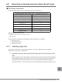
1.2
Main Features
■ Devices that can be mounted on this rack
This rack can accommodate the following types of Fujitsu products: (*1)
・ PC servers: "PRIMERGY"
・ UNIX servers: "SPARC Enterprise," "PRIMEPOWER," and "S series"
・ Storage systems: "ETERNUS"
・ Mission Critical IA Servers: (MC IA Servers) "PRIMEQUEST 510A" (*2)
・ Network products: (SR-S series, etc.)
*1)
For more information, consult your Fujitsu sales representative.
*2)
Note that the PRIMEQUEST 520A, 520, and 420 models of MC IA servers cannot be
mounted in this 19-inch rack. The PRIMEQUEST 520A, 520, and 420 models can be
mounted in the following racks.
・ MC-R7RC11/MC-R7RC21
・ MC-R7RC12/MC-R7RC22
・ MC-R8RC11/MC-R8RC21
・ MC-R8RC12/MC-R8RC22
■ Stabilizer requirement depends on the rack installation method followed
Whether you will need to use stabilizers on your 19-inch rack will depend on the rack installation
method that you follow.
■ Devices mounted in the rack center
Although devices are mounted toward the right side on conventional standard and global racks (when
viewed from the front), on the 19-inch rack, they are mounted in the center. This ensures that cables
do not become concentrated on one side of the rack, and it makes wiring easier.
■ Cable holders provided as standard equipment
Cable holders are provided as standard equipment on the cable routes in the rack, so that cables can
be managed more easily.
■ Improved cooling performance
The front and rear doors of this 19-inch rack provide an opening ratio of 80 % for improved cooling
performance. (The opening ratio of conventional standard racks and global racks is 60%.)
■ Flexible placement of the door's rotation axis
The position of the door's rotation axis can be changed at the rack installation site.
E
1 Overview
73
2
Precautions on Rack Installation and
Operation
This section explains precautions on rack delivery, installation, and operation.
2.1
Installation Site Precautions
WARNING
・ Do not place the rack in an unstable location subject to excessive vibration (over
200Gal), or in a location that is not level. Doing so may adversely affect the
stable operation of equipment or cause the rack to tip over, potentially resulting in
serious injury.
Confirm that the rack and rack-mount devices are fixed as a measure for
earthquakes exceeding 250Gal.
・ Confirm that the rack is installed on a surface with an adequate load-bearing
capacity.
If the floor has insufficient load-bearing capacity, it may collapse since the
maximum load associated with the rack may reach about 1,000 kg.
・ Secure a sufficient installation area to ensure normal operation and maintenance
of the rack system.
・ To reduce the risk of failure, fire, or electric shock, do not place metallic objects or
containers bearing water, such as vases, flowerpots, or drinking glasses, on or
near the rack.
・ Avoid placing the rack in locations exposed to oil vapors or excessive humidity or
dust, or with poor ventilation, or locations where flammable materials are stored.
Storage or use of the rack in such areas may lead to failure, fire, or electric shock.
CAUTION
・ To avoid the risk of failure, do not install the rack in locations exposed to high
temperatures (including areas near heaters) or direct sunlight. Do not install the
rack in locations where temperatures drop below 10 ℃ .
・ Always confirm that rack openings such as ventilation holes are not obstructed.
Blocking ventilation holes may cause the internal temperature of the rack to
become excessively high, leading to failure or fire.
74
2.2
Precautions during Transportation
This section explains precautions that must be followed when transporting the 19-inch rack.
・ Before delivering the rack, confirm that the transport route is wider than the rack.
・ Use of a board may be necessary where the surface of the transport route is uneven..
19-inch
rack
Board (steel plate, etc.)
• Because the maximum weight including the rack can be about 1,000 kg, confirm beforehand that
there is no problem with the transport route.
Example: Type of floors on the transport route
Ensure that the floor has sufficient load capacity to hold the rack, and that the casters do
not sink into the surface of the floor or catch on the floor.
• When transporting the rack to an upper or lower floor of a building, confirm beforehand whether
an elevator is available for use. If an elevator is available for use, confirm that the rack weight
does not exceed the laden weight capacity of the elevator.
• When transporting the rack, push the lower part of the rack rather than the middle of the rack to
keep the rack from falling over. The barycentric position of the rack can be higher than the center
of the rack depending on where individual devices are installed.
Also, do not push on the rack sides. Doing so may cause the rack to fall over.
• Pushing against the center of the front door or the air vent opening may cause them to become
deformed. Move the rack by pushing against the door corners.
• Condensation will build up inside the devices installed in the rack if the rack is moved from a cold
location to a warm room.
Prevent the buildup of condensation in the room where the rack is installed by ensuring that the
room temperature does not increase faster than 15 ℃ per hour. See the following table for information on condensation..
Room temperature
10
Relative
humidity
(%)
15
20
25
30
35
40
20
-7
-5
-3
1
5
9
13
40
-3
2
7
11
16
20
24
60
3
8
13
17
22
26
31
80
7
12
17
22
26
31
-
90
9
13
19
24
29
34
-
Remarks
Example:
Condensation will begin to
build up in a device if its
internal temperature is
17 ℃ or less and the room
temperature is 25 ℃ and
humidity is 60%.
2 Precautions on Rack Installation and Operation
E
75
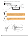
・ Exercise reasonable care in safekeeping the key supplied with the rack to ensure that it is not lost.
At the time of shipment, the key may either be attached to the rack (as shown in the figure below)
or included in the box containing other supplied components.
Key is here
K ey closes
Bag with key ins
Front door
[When the key is attached to the rack]
2.3
Precautions for Installation and Operation
■ Securing adequate clearance for ventilation and maintenance
When installing the rack, secure adequate clearance for ventilation and maintenance, as shown below.
400mm
700mm
500mm
1000mm
700mm
Clearance
for ventilation
and maintenance
200mm
1050mm
Top view
of the rack
Front view
of the rack
2000mm
Front
of the rack
1400mm
1400mm
1400mm
3500mm
76
■ Measures against earthquakes
To have the rack system withstand earthquakes measuring more than 250 Gal, secure the system with
adequate earthquake-proofing measures. The earthquake-proofing measures include using leveling
feet and using the optional Quake Proof Stabilizer kit.
WARNING
`
Use bolts to secure the rack to the floor (slab).
Failure to use bolts to secure the rack to the floor (slab) may cause the rack to fall
over during any earthquake with a seismic intensity exceeding 250 Gal.
If the rack falls over, the result may be severe injury, death, and/or damage to the
devices in the rack and the surrounding area.
・ Quake Proof Stabilizer kit
Rack type
Quake Proof Stabilizer kit type
Base rack (19R-174A2)
19R-17ST1
Expansion rack (19R-174B2)
19R-17ST2
■ Securing the rack using the leveling feet
Install the rack so that it is anchored with the leveling feet that are provided on the bottom of the rack.
Adjust the leveling feet so that the rack is level.
`
Keep the casters 1 to 2 mm above the floor.
Casters
Top view
of the rack
Leveling feet
(Front)
E
2 Precautions on Rack Installation and Operation
77
■ Protecting the rack from falling over
CAUTION
・ When installing a rack that comes with stabilizers, be sure to attach the
stabilizers. If not, the rack may tip over when a device is drawn out from the rack.
・ When installing a rack that comes with no stabilizers, be sure to anchor the rack
to a stabilizing surface. The rack may tip over if it is not anchored to a stabilizing
surface.
For information on the stabilizer attaching procedure, see Section 3.4, "Installing the Rack."
■ Mounting a blank panel
CAUTION
・ If the blank panel is not mounted, the exhaust will be drawn into the device again
through the suction surface, which may result in device malfunction or a
shortened service life of the device.
Attach the blank panel to the parts of the rack where no devices are installed.
For information on the procedure for mounting the blank panel, see Section 4.6, "Blank Panel
Mounting Procedure."
78
■ Other precautions
CAUTION
・ Do not remove the front or rear doors of the rack. The sheer weight of these
doors may result in serious injury if they fall over.
If the doors need to be removed, contact a Fujitsu Limited maintenance engineer.
・ Contact a Fujitsu Limited maintenance engineer before attempting to move the
rack after installing it. Transporting or moving the rack without taking the proper
procedures and precautions may result in damage to the rack.
・ To prevent the rack from becoming unstable, do not climb on it or lean against it.
E
2 Precautions on Rack Installation and Operation
79
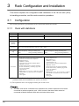
3
Rack Configuration and Installation
This section explains the configuration and installation of the 19-inch rack (40U),
its handling procedure, and the rack connection procedure.
3.1
Configuration
This section provides the specifications of the 19-inch rack and its accessories.
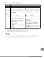
3.1.1
Rack with stabilizers
Item
Product name
Specifications
19-inch rack Model 1740 base rack
19-inch rack Model 1740 expansion rack
Type name
19R-174A1
19R-174B1
Appearance
Coated black (front and rear doors with punched metal finish)
Unit
mounting
capacity
40U
Size (w) x (d)
x (h) mm
700 x 1272 (including stabilizers, rack unit: 1050) x 2000)
Load capacity
(kg)
Total rack capacity: 943 kg (*1)
Total load capacity: 800 kg (excluding rack)
Rack:
143 kg (including stabilizers)
Security
Accessories
Total rack capacity: 910 kg (*1)
Total load capacity: 800 kg (excluding rack)
Rack:
110 kg (including stabilizers)
Front and rear doors locked with keys (Key operation is required to lock handle.)
・ Front door, rear door, and a pair of side covers
(attached to the rack before shipment)
・ Rack door keys: 2
・ Stabilizer: 1 (front)
・ Cage nut/screws (washers attached before
shipment): 50 each
・ (If cage nuts/screws are used for mounting
devices at the factory, remaining cage nuts/
screws are supplied.)
・ Cage nut tool
・ Blank panels: 1U x 3, 2U x 5, and 3U x 3 panels
・ Cable holders: 24 (attached to the rack before
shipment)
・ User's guide
・ Front door and rear door (attached to the rack
before shipment) (*2)
・ Rack door keys: 2
・ Stabilizer: 1 (front)
・ Connection kit: 1 set
・ Cage nut/screws (washers attached before
shipment): 50 each
・ (If cage nuts/screws are used for mounting
devices at the factory, remaining cage nuts/
screws are supplied.)
・ Cage nut tool
・ Blank panels: 1U x 3, 2U x 5, and 3U x 3 panels
・ Cable holders: 24 (attached to the rack before
shipment)
・ User's guide
*1) Ensure that the floor load based on the total rack capacity does not exceed the floor strength
(withstand load) at the installation site (such as an office).
*2) The expansion rack is not equipped with a pair of side covers.
`
80
The base rack can be connected to an expansion rack, and the expansion rack can be
connected to another expansion rack. Note, however, that these racks cannot be
connected to Model 1640 and 1624 racks and other series racks.
3.1.2
Rack without stabilizers
Item
Product name
Specifications
19-inch rack Model 1740 base rack
19-inch rack Model 1740 expansion rack
Type name
19R-174A2
19R-174B2
Appearance
Coated black (front and rear doors with punched metal finish)
Unit mounting
capacity
40U
Size (w) x (d) x
(h) mm
700 x 1050 x 2000
Load capacity
(kg)
Security
Accessories
Total rack capacity: 935 kg (*1)
Total load capacity: 800 kg (excluding rack)
Rack:
135 kg
Total rack capacity: 902 kg (*1)
Total load capacity: 800 kg (excluding rack)
Rack:
102 kg
Front and rear doors locked with keys (Key operation is required for handle locking.)
・ Front door, rear door, and a pair of side covers
(attached to the rack before shipment)
・ Rack door keys: 2
・ Cage nuts/screws (washers attached before
shipment): 50 each
・ (If cage nuts/screws are used for mounting
devices at the factory, remaining cage nuts/
screws are supplied.)
・ Cage nut tool
・ Blank panels: 1U x 3, 2U x 5, and 3U x 3 panels
・ Cable holders: 24 (attached to the rack before
shipment)
・ User's guide
・ Front door and rear door (attached to the rack
before shipment) (*2)
・ Rack door keys: 2
・ Connection kit: 1 set
・ Cage nuts/screws (washers attached before
shipment): 50 each
・ (If cage nuts/screws are used for mounting
devices at the factory, remaining cage nuts/
screws are supplied.)
・ Cage nut tool
・ Blank panels: 1U x 3, 2U x 5, and 3U x 3 panels
・ Cable holders: 24 (attached to the rack before
shipment)
・ User's guide
*1) Ensure that the floor load based on the total rack capacity does not exceed the floor strength
(withstand load) at the installation site (such as an office).
*2) The expansion rack is not equipped with a pair of side covers.
`
The base rack can be connected to an expansion rack, and the expansion rack can be
connected to another expansion rack. Note, however, that these racks cannot be
connected to Model 1640 and 1624 racks and other series racks.
E
3 Rack Configuration and Installation
81
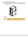
3.2
Opening the Front Door
1 Unlock the door with the key for the rack. From the front of the door, lift and
pull the rack handle.
CAUTION
・ Close the front door after fully securing the installed devices. Failure to do so
may cause the devices to fall off the rack and be damaged in the event of an
earthquake.
82
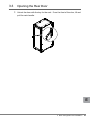
3.3
Opening the Rear Door
1 Unlock the door with the key for the rack. From the front of the door, lift and
pull the rack handle.
E
3 Rack Configuration and Installation
83
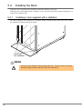
3.4
Installing the Rack
When the rack is supplied with a stabilizer, attach the stabilizer to the rack.
When the rack is not supplied with a stabilizer, secure the rack in position with the leveling feet or a
Quake Proof Stabilizer Kit.
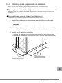
3.4.1
Installing a rack supplied with a stabilizer
The rack is supplied with a stabilizer, as standard, which is attached on the front of the rack. Attach
the stabilizer as shown in the figure below.
Securing
the stabilizer
WARNING
・ Always use the stabilizers when installing the rack. Failure to do so may cause
the rack to tip over when a device in the rack is pulled out.
84
3.4.2
Installing a rack supplied with no stabilizers
Secure the rack to the floor using the leveling feet or the Quake Proof Stabilizer kit.
■ Securing the rack using the leveling feet
Bolt the leveling feet to the floor through the M20 holes of 17 mm deep in the ground plate of the
leveling feet.
■ Securing the rack using the Quake Proof Stabilizer kit
The procedure for attaching the Quake Proof Stabilizer kit is shown below.
1 Attach the kit stabilizers to the front/rear and right/left sides of the rack.
`
The Quake Proof Stabilizer kit is an optional product.
2 Attach the stabilizers to the rack using three bolts for the front and right/left
sides and two bolts for the rear.
3 Anchor the kit stabilizers to the floor.
1. Anchor the stabilizers on the front/rear sides to the floor, each with two bolts.
2. Anchor the kit stabilizers on the right/left sides to the floor, each with three bolts.
Securing the stabilizer
with two bolts (front/rear)
Securing the stabilizer
with three bolts (sides)
E
3 Rack Configuration and Installation
85
3.5
Connecting Racks
To use additional expansion racks, connect additional racks to the existing rack (base rack or
expansion rack).
WARNING
・ To prevent equipment damage and electric shock, turn off the power to the server
and peripherals and disconnect the power cables from the outlet before
connecting racks.
CAUTION
・ To prevent injury, ensure that at least two persons perform the rack connection
work.
・ You may get on a stepladder when working on the upper part of the rack. Be
careful not to fall from the stepladder.
・ Do not put your foot on the racks when connecting racks.
■ Confirming components
Confirm that all components of the connection kit that need to be supplied with an expansion rack
have been delivered (see the table below).
Component name
Quantity
Upper mounting fixture
1
Lower mounting fixture
2
Shield rubber for connection
2
Remarks
M12 bolt
4
For upper connection
M8 bolt
4
For lower connection
Also, prepare the necessary tools:
・Phillips screwdrivers (No. 2 and No. 3 bits)
・Hexagon wrenches (M8 bolts: Socket size 13; M12 bolts: Socket size 19)
Also, prepare a stepladder because some of the work will need to be performed at height.
86
The procedure for connecting racks is shown below (example: connecting an expansion rack to the
right of the base rack).
1 Removing the side cover of the existing rack.
Remove the eight M6 screws securing the side cover, and then remove the side cover.
`
Be careful not to lose the M6 screws removed here. They will be used later.
’
Side cover
M6 screw
E
3 Rack Configuration and Installation
87
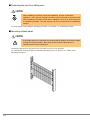
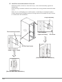
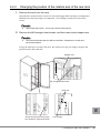
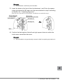
2 Remove the Quake Proof Stabilizer kit component from the existing rack
side to which another rack will be connected.
Remove all screws or bolts from the Quake Proof Stabilizer kit components on the
connection side securing the rack to the building floor, and then remove the Quake Proof
Stabilizer kit components from the rack connection side.
Also, remove the screws or bolts from the front/rear Quake Proof Stabilizer kit components
that are on the side to which another rack will be connected.
`
Be careful not to lose the Quake Proof Stabilizer kit components and bolts. They
will be used later.
’
Bolt on the rack connection side
Quake Proof
Stabilizer kit
component (rear)
Quake Proof
Stabilizer kit
component (side)
Quake Proof
Stabilizer kit
component (front)
Bolt that secures
the stabilizer
to the floor
Bolt on the connection side
88
Bolt that secures
the stabilizer to the rack
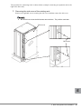
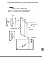
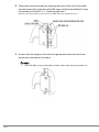
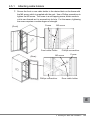
3 Attach the shield rubber on the connection side.
Peel off the backing paper from the shield rubber, and attach it to the frame on the connection
side in order from the top of the rack.
Attach the shield rubber to the front and rear frames of the rack.
’
Frame
ࡈࡓ
Shield rubber
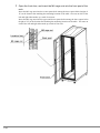
4 Align the height of the expansion rack with that of the existing rack.
Line up the side of the expansion rack with the side of the existing rack, and then adjust the
expansion rack feet to align the expansion rack height with that of the existing rack.
E
3 Rack Configuration and Installation
89
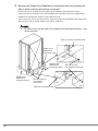
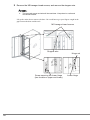
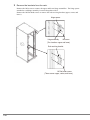
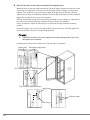
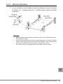
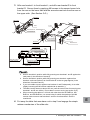
5 Attach the Quake Proof Stabilizer kit components to the front, side, and rear
of the expansion rack.
Attach the front and rear Quake Proof Stabilizer kit components of the expansion rack and
the side stabilizer previously removed from the existing rack to the expansion rack. Use the
bolts attached to the Quake Proof Stabilizer kit components and those removed from the
existing rack. At this stage, tighten the bolts only temporarily. They will need to be
tightened firmly after the mounting fixtures are attached.
The front and rear Quake Proof Stabilizer kit components each have three bolt holes. On
each side, the bolt for the one closest to the existing rack will be tightened together with the
mounting fixture later. So, leave that bolt unapplied for now.
(See the following page.)
’
Bolts that secure
the Quake Proof Stabilizer kit
components
Bolts that secure
the Quake Proof Stabilizer kit
components
90
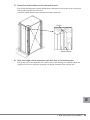
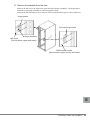
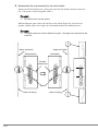
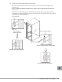
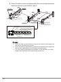
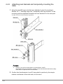
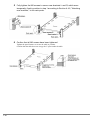
6 Attach the mounting fixtures and fully tighten the bolts securing the Quake
Proof Stabilizer kit components.
Secure the upper mounting fixture with four M12 bolts.
Note: Be careful when working at height on the top cover. Never put your foot on the rack
because it is very dangerous.
Attach the two lower mounting fixtures, one on the lower front and one on the lower rear of
the rack, each with two M8 bolts.
Use the M8 bolts used for the Quake Proof Stabilizer kit. If you are not using the Quake
Proof Stabilizer kit, use the bolts that come with the connection kit.
Note: When the Quake Proof Stabilizer kit components are attached, some of the M8 bolts of
the Quake Proof Stabilizer kit will not be required and, therefore, some of the bolts that
come with the connection kit will remain unused.
Fully tighten the bolts that were temporarily tightened.
’
Upper mounting fixture
M8 bolt
M12 bolt
Lower mounting fixtur
E
3 Rack Configuration and Installation
91
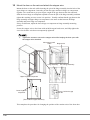
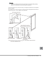
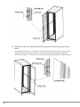
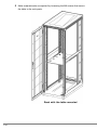
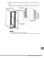
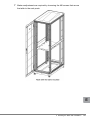
7 Mount the side cover on the expansion rack.
Lastly, mount the side cover, which was removed from the existing rack, with the M6 screws,
which were also removed from the existing rack. This completes the rack-connection
procedure.
’
Side cover
M6 screw
92
4
Handling the Rack after Installation
This section explains how to handle the rack after installation.
4.1
’
4.1.1
Cage nut Insertion and Removal Procedures
Insertion
1 Install the cage nut from the inside of the rack. Insert one edge of the cage
nut into the cage nut hole of the rack.
The following figure shows the case where the edge of the cage nut is inserted into the lower
hole.
’
2 From the outside of the rack, insert the tip of the cage nut tool into the hole
that has the installed cage nut, and snap the other edge of the cage nut into
the hole.
’
Direction of edge of the cage
nut tool
Cage nut tool
E
4 Handling the Rack after Installation
93
3 Pull on the cage nut tool to lock the cage nut in position.
’
Press the cage nut
to the insertion direction
(indicated by the arrow).
Pull on the cage nut tool
(to the direction indicated
by the arrow).
4.1.2
Removal
CAUTION
Before pushing down on the tool or standard screwdriver, confirm that the tip of
the tool or standard screwdriver is completely inserted between the edge of the
cage and the mounting flange. If the tip is inserted incompletely, the edge of the
tool or standard screwdriver may slip off, leading to potential injury.
CAUTION
Secure the cage nut such as with adhesive tape to prevent it from falling into the
rack. When holding the cage nut between your fingertips, be sure to grasp its left
and right sides.
■ Procedure using the cage nut tool
1 Insert the tip of the cage nut tool between the cage and the mounting
flange, and then push the on the edge of the cage.
’
94
CAUTION
Be sure not to place any finger anywhere past the points indicated. Otherwise,
the finger may strike the rack when you push on the cage, which may lead to
injury.
2 Push down on the cage nut tool to extract the edge of the cage.
Be careful not to drop the cage nut.
’
`
Keep the tool in a safe and convenient location because it will be required when
the system is expanded or relocated in the future.
■ Procedure using a standard screwdriver
CAUTION
Secure the cage nut such as with adhesive tape to prevent it from falling into the
rack. When holding the cage nut between your fingertips, be sure to grasp its left
and right sides.
E
4 Handling the Rack after Installation
95
1 Insert the tip of a standard screwdriver between the edge of the cage and
the mounting flange, and then press the edge of the cage.
’
2 Push down on the standard screwdriver to remove the cage nut.
’
96
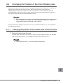
4.2
Changing the Position of the Door Rotation Axis
The position of the door rotation axis can be changed from the position at shipment. At the time of
shipment, the front door turns on the left axis, and the rear door turns on the right axis.
Changing the position of the rotation axis involves the repetitive action of removing parts and
reinstalling them at different locations. Work carefully to avoid causing deformation, breakage, or
loss of parts during the removal and reinstallation of parts.
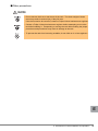
`
Removed parts are all reused. No excess parts should be left over. Note that the
rack is supplied with no spare parts. Removing and installing some parts will
require certain degrees of strength. Work carefully.
General tools such as Phillips screwdrivers (No. 2 bit), standard screwdrivers, etc., are required for
the following operations.
4.2.1
Changing the position of the rotation axis of the front door
1 Remove the door from the rack.
Open the door, loosen the lower screws on each of the upper and lower hinge sets, and then
pull down the lower hinges. Use a Phillips screwdriver to loosen the screws.
`
Just loosen the screws. You do not need to remove them.
E
4 Handling the Rack after Installation
97
2 Remove the M5 hexagon head screws, and remove the stopper wire.
`
The removed screws and wire will be used later. Keep them in a safe and
convenient location.
Lift up the entire door to remove the door. Be careful not to get your fingers caught in the
gap between the door and the rack.
’
M5 hexagon head screws
Stopper wire
Hinge set
98
Screw securing the lower hinge
(two locations: upper and lower)
Lower hinge
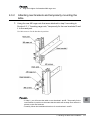
3 Remove the brackets from the rack.
Remove the M5 screws to remove the upper and lower hinge assemblies. The hinge spacer
attached to each hinge assembly is removed together with it.
Remove the M5 flat head screws to remove rod receiving brackets (upper, center, and lower).
’
Hinge spacer
Rod receiving bracke
M5 screw
Hinge assembly
(Two locations: upper and lower)
M5 flat head screws
(three screws: upper, center, and lower)
E
4 Handling the Rack after Installation
99
4 Install the removed brackets in the rack.
Install the brackets, which were removed in step 3, on the side horizontally opposite the
standard side.
Secure the hinge assemblies with M5 screws and the rod receiving brackets with M5 flat head
screws.
Each screw is a self-tapping screw, which requires a certain degree of strength to tighten.
Confirm that the hinge assemblies and rod receiving brackets are installed correctly as shown
in "Normal state after installation."
’
Hinge assembly
Rod receiving bracket
M5 screw
Side cover
(Two locations:
upper and lower)
M5 flat head screw
(Three locations: upper, center, lower)
Side cover
(Normal state after installation)
(Normal state after installation)
100
5 Remove the door handle (with rods) and the Fujitsu logo from the door.
Push the standard screwdriver horizontally against each of the upper and lower rod
supporters to remove them.
`
The upper rod may fall on you. Work carefully.
Remove the upper and lower M5 screws securing the door handle.
Remove the door handle together with the rods from the door.
Remove the M4 screw to remove the Fujitsu logo. Place your hand on the Fujitsu logo while
removing the M4 screw, to prevent the Fujitsu logo from falling.
’
Rod
Fujitsu
logo
Standard
screwdriver
Rod supporter
(two locations: upper and lower)
Door handle
M4 screw
Door
Door handle M5 screw
Rod E
4 Handling the Rack after Installation
101
6 Reassemble the rod assembly for the door handle.
Remove the M3 bind head screw securing the rod to the door handle, and then remove the
rod. (The spacer is removed together with it.)
`
Be careful not to lose the spacer.
While holding the upper (short) rod with the curved end facing the left, secure the rod
together with the spacer to the right side of the handle with the M3 bind head screw.
`
The upper and lower rods are different in length. The upper rod is shorter than the
lower rod.
’
Upper rod (short)
Upper rod (short)
(Disassemble)
(Assemble)
M3 bind
head screw
Spacer
Lower rod (long)
102
Lower rod (long)
7 Install the door handle and rods.
Before starting this work, turn the door upside down.
Insert the assembly of the door handle and rods from the front of the door in such a way that
the upper (short) rod will be on top.
Secure the door handle with the M5 screws.
Secure the upper and lower rods with the rod supporters.
’
Door handle
Door
Upper rod
(short)
Lower rod (long)
Rod
Rod supporter (Normal state
after installation)
(Upper and lower supporters)
M5 screw
Door handle
E
103
8 Attach the Fujitsu logo.
Secure the Fujitsu logo using an M4 screw from the rear of the door.
The standard location for the logo is 103 mm from the left side and 122 mm from the top.
’
M4 screw
122
Fujitsu logo
103
104
9 Attach the stopper wire to the door and adjust the upper and lower hinge
set positions.
Attach the stopper wire to the door and temporarily tighten the M5 hexagon head screw. This
screw will be fully tightened when the wire is attached to the rack.
Adjust the hinge positions. (The upper hinge set component has been left loose since the
door was removed.) Lower the upper hinge set component as far as it will go and then
tighten the retaining screw. Fully tighten the screw while taking care not to tilt the hinge.
`
Tighten the retaining screws for the upper hinge set component while pressing
down on it in the direction of the lower hinge set component.
Loosen the retaining screws of the lower hinge set component and then lower the component
as far as it will go. The retaining screws of the lower hinge set component will be fully
tightened after the door is mounted on the rack. For now, tighten it only temporarily.
’
Stopper wire
M5 hexagon head screw
Upper hinge set component
(view from the front of the door)
Hinge retaining screw
Full tightening
View from the rear of the door
Hinge set
Lower hinge
set component
(Two locations: upper and lower)
4 Handling the Rack after Installation
E
105
10 Mount the door on the rack and attach the stopper wire.
Mount the door on the rack while inserting the pin of the hinge assembly into the hole of the
upper hinge set component. Insert the pin into the upper and lower hinge set components
together. Be careful not to get your fingers caught in the gap between the door and rack.
Slide the lower hinge set component upward to insert the pin of the hinge assembly, and then
tighten the retaining screw to secure it in position. Visually confirm that the gap between the
hinge assembly and upper hinge set component is the same as that between the hinge
assembly and lower hinge set component.
If they are different, adjust the lower hinge set component or hinge assembly mounting
position.
Secure the stopper wire to the frame with an M5 hexagon head screw, and fully tighten the
screw for the door wire that was temporarily tightened.
`
Tighten the screws to secure the stopper wire while keeping the door open with
the stopper wire stretched.
’
M5 hexagon head
screw
Stopper wire
Hinge assembly
Pin of hinge assembly
Upper hinge set component
Lower hinge set
component
Confirm the gap
(Two locations: upper and lower)
This completes the procedure for changing the position of the rotation axis of the front door.
106
4.2.2
Changing the position of the rotation axis of the rear door
1 Remove the door from the rack.
Open the door, loosen the lower screws on each of the upper and lower hinge set components,
and then lower the lower hinge set component. Use a Phillips screwdriver to loosen the
screws.
`
Just loosen the screws. You do not need to remove them.
2 Remove the M5 hexagon head screws, and then remove the stopper wire.
`
The removed screws and wire will be used later. Keep them in a safe and
convenient location.
Lift up the entire door to remove the door. Be careful not to get your fingers caught in the
gap between the door and rack.
’
Stopper wire
M5 hexagon head screw
Hinge set
E
Screw securing the lower hinge
(two locations: upper and lower)
Lower hinge
4 Handling the Rack after Installation
107
3 Remove the brackets from the rack.
Remove the M5 screws to remove the upper and lower hinge assemblies. The hinge spacer
attached to each hinge assembly is removed together with it.
Remove the M5 flat head screws to remove the rod-receiving brackets (upper, center, and
lower).
’
Hinge spacer
Hinge assembly
M5 screw
(Two locations: upper and lower)
Rod receiving bracket
M5 flat head screws
(Three screws: upper, center, and lower)
108
4 Install the removed brackets to the rack.
Install the brackets, which were removed in step 2, on the side horizontally opposite the
standard side.
Secure the hinge assemblies with M5 screws and the rod-receiving brackets with M5 flat
head screws.
Each screw is a self-tapping screw, which requires a certain degree of strength to tighten.
Confirm that the hinge assemblies and rod-receiving brackets are installed correctly as shown
in "Normal state after installation."
’
Hinge assembly
M5 screw
(Two locations:
upper and lower)
Rod-receiving bracket
M5 flat head screw
(Three locations: upper, center, lower)
(Normal state after installation)
Side cover
(Normal state after installation)
E
4 Handling the Rack after Installation
109
5 Remove the door handle (with rods) from the door.
Insert the standard screwdriver horizontally into each of the upper and lower rod supporters,
and then remove all supporters.
`
The upper rod may fall on you. Work carefully.
Remove the upper and lower M5 screws securing the door handle.
Remove the door handle together with the rods from the door.
’
Rod
Rod supporter
(two locations: upper and lower)
Standard
screwdriver
Door handle
Door handle
Door
M5 screw
Rod
110
6 Reassemble the rod assembly for the door handle.
Remove the M3 bind head screw securing the rod to the door handle, and then remove the
rod. (The spacer is removed together with it.)
`
Be careful not to lose the spacer.
While holding the upper (short) rod with the curved end facing the left, use the M3 bind head
screw and the spacer to secure the rod to the right side of the handle.
`
The upper and lower rods are different in length. The upper rod is shorter than the
lower rod.
’
Upper rod (short)
Upper rod (short)
(Assemble)
(Disassemble)
Spacer
M3 bind
head screw
Lower rod (long)
Lower rod (long)
E
4 Handling the Rack after Installation
111
7 Install the door handle and rods.
Before starting this work, turn the door upside down.
Insert the assembly of the door handle and rods from the front of the door in such a way that
the upper (short) rod will be on top.
Secure the door handle with the M5 screws.
Secure the upper and lower rods with the rod supporters.
’
Door
Door handle
Upper rod (short)
Lower rod (long)
Upper rod (short)
(Normal state
after installation)
(Upper and lower supporters)
Rod supporter
Door handle
M5 screw
8 Attach the stopper wire to the door and adjust the upper and lower hinge
set component positions.
Attach the stopper wire to the door and temporarily tighten the M5 hexagon head screw. This
screw will be fully tightened when the wire is attached to the rack.
Adjust the hinge positions. (The upper hinge set component has been left loose since the
door was removed.) Lower the upper hinge set component as far as it will go and then
tighten the retaining screw. Fully tighten the screw while taking care not to tilt the hinge.
112
`
Tighten the retaining screws for the upper hinge set component while pressing
down on it in the direction of the lower hinge set component.
Loosen the retaining screws of the lower hinge set component and then lower the component
as far as it will go.
The retaining screws of the lower hinge set component will be fully tightened after the door is
mounted on the rack. For now, tighten it only temporarily.
’
M5 hexagon head screw
Stopper wire
Upper hinge set component
(view from the front of the door)
Hinge
retaining screw
Full tightening
Lower hinge Hinge set
set component
(Two locations: upper and lower)
View from the rear of the door
E
4 Handling the Rack after Installation
113
9 Mount the door on the rack and attach the stopper wire.
Mount the door on the rack while inserting the pin of the hinge assembly into the hole of the
upper hinge set component. Insert the pin into the upper and lower hinge set components
together. Be careful not to get your fingers caught in the gap between the door and rack.
Slide the lower hinge set component upward to insert the pin of the hinge assembly, and then
tighten the retaining screw to secure it in position.
Visually confirm that the gap between the hinge assembly and upper hinge set component is
the same as that between the hinge assembly and lower hinge set component.
If they are different, adjust the lower hinge set component or hinge assembly mounting
position.
Secure the stopper wire to the frame with an M5 hexagon head screw, and fully tighten the
screw for the door wire that was temporarily tightened.
`
Tighten the screws to secure the stopper wire while keeping the door open with
the stopper wire stretched.
Changing the position of the rotation axis of the rear door is completed.
’
Stopper wire
M5 hexagon head screw
Pinof hinge assembly Hinge assembly
(Two locations: upper and lower)
Upper hinge
Confirm the gap
114
Lower hinge
4.3
Mounting a General-purpose Table (Fixed Type)
■ Confirming components
Confirm that all components have been delivered (see the table below).
General-purpose Table (Fixed Type)
Type name: 19R-16TR1
Component name
Quantity
Table
1
Rear bracket L
1
Rear bracket R
1
M6 cage nut
8
M6 bolt
4
M6 screw
8
Belt
2
Installation Guide
1
Also, prepare the necessary tools:
・Phillips screwdrivers (No. 2 and No. 3 bits)
・Cage nut tool
The procedure for mounting a general-purpose table (fixed type) is as follows:
1. Insert cage nuts.
2. Attach rear brackets.
3. Mounting the table.
4.3.1
Inserting cage nuts
Insert cage nuts into the rack posts (front and rear). For more information on the mounting
procedure, see Section 4.1.1, "Insertion."
1 Open the front door, and insert the M6 cage nuts into the front post of the
rack.
Insert cage nuts into two upper and lower square holes out of three between the location lines.
The mounting locations are as follows: one nut in each of the upper and lower square holes
among the three square holes (height of 1U) at the location line marking the mounting
location of the table. Two nuts on each of the left and right sides make up a total of four nuts.
E
4 Handling the Rack after Installation
115
2 Open the rear door, and insert the M6 cage nuts into the rear post of the
rack.
The mounting locations are as follows: one nut in each of the upper and lower square holes
among the three square holes (height of 1U) at the location line marking the mounting
location of the table. Two nuts on each of the left and right sides make up a total of four nuts.
116
`
4.3.2
Align the heights of all attached M6 cage nuts.
Attaching rear brackets and temporarily mounting the
table
1 Using the rear M6 cage nuts that were attached in step 2 according to
Section 4.3.1, "Inserting cage nuts," temporarily fix the rear brackets R and
L to the rack post.
Use M6 screws to fix the brackets in position.
・In step 2, you will mount the table on rear brackets L and R. Temporarily fix the
rear brackets in position to the extent that the table will not drop down when it is
placed on the rear brackets.
・Carefully follow the installation directions for rear brackets L and R.
4 Handling the Rack after Installation
E
117
2 Temporarily mount the table by inserting the hook at the front of the table
into the square hole right above the M6 cage nut that was attached in step
2 according to Section 4.3.1, "Inserting cage nuts."
Place the rear of the table on rear brackets L and R that were attached in step 1.
3 Confirm that the heights of the left and right square holes into which the
hooks were inserted are the same.
`
118
Since the table is only provisionally mounted, refrain from placing any loads on it.
4.3.3
Mounting the table
1 Secure the table to the M6 cage nuts that were attached in step 2 according
to Section 4.3.1, "Inserting cage nuts." Use M6 screws to secure the table
in position.
`
`
Start work after confirming that rear brackets L and R will not fall down when the
table is placed on them.
When mounting the table provisionally, ensure that the table is securely mounted
with the front hook fully inserted in the relevant square hole. Also, ensure that the
rear part of the table is securely mounted on rear brackets L and R.
Do not take away the supporting hand until the table is fixed in position.
E
4 Handling the Rack after Installation
119
2 Secure the table in position by applying M6 bolts to the first and third screw
holes from the rear of rear brackets L and R.
Table
M6 bolts
M6 screws
B
G
Table
B
B
Rear bracket R
A
C
G
A
Rack post
C
Rear bracket R
Rack post
A
C
Rear bracket L
Rear bracket R
Table
Screw holes of rear bracket R
used to secure the table in position
* The same screw hole positions
on rear bracket L
First screw hole
from rear
Third screw hole
from rear
Section G-G
`
`
`
120
Secure the table in position while fully pressing rear brackets L and R against the
rack posts (in the direction of arrow A).
Secure the table in position while fully pressing rear brackets L and R against the
table so that no gaps appear (in the directions of arrows B and C).
If you are unable to press against rear brackets L and R adequately, do so after
slightly loosening the M6 screws marked with an asterisk (*).
3 Fully tighten the M6 screws to secure rear brackets L and R, which were
temporarily fixed in position in step 1 according to Section 4.3.2, " Attaching
rear brackets and temporarily mounting the table," to the rack posts.
4 Confirm that all M6 screws and M6 bolts have been tightened.
Confirm that the table does not occupy the U space under the table.
E
4 Handling the Rack after Installation
121
5 Make readjustments as required by loosening the M6 screws that secure
the table to the rack posts.
122
4.4
Mounting a General-purpose Table
(Movable Type)
■ Confirming components
Confirm that all components have been delivered (see the table below).
General-purpose Table (Movable Type)
Type name: 19R-16TR2
Component name
Quantity
Table
1
Rear bracket L
1
Rear bracket R
1
M6 cage nut
8
M5 cage nut
2
M6 screw
12
Belt
2
Installation Guide
1
Also, prepare the necessary tools:
・Phillips screwdrivers (No. 3 bit)
・Cage nut tool
The procedure for mounting a general-purpose table (fixed type) is as follows:
1. Insert cage nuts.
2. Attach rear brackets.
3. Mount the table.
4.4.1
Inserting cage nuts
Insert the M5 and M6 cage nuts into the rack posts (front and rear). For more information on the
mounting procedure, see Section 4.1.1, "Insertion."
E
4 Handling the Rack after Installation
123
1 Open the front door, and insert the M6 cage nuts into the front post of the
rack.
Insert the M5 cage nuts into the center square hole among the three square holes (height of
1U) at the location line marking the mounting location of the table. One nut on each of the
left and right sides makes up a total of two nuts.
Insert the M6 cage nuts into the upper and lower square holes among the three square holes
(height of 1U) at the location line marking the mounting location of the table. Two nuts on
each of the left and right sides make up a total of four nuts.
124
2 Open the rear door, and insert the M6 cage nuts into the rear post of the
rack.
Insert M6 cage nuts into two upper and lower square holes out of three between location lines
on the rack post. Two nuts on each of the left and right sides make up a total of four nuts.
`
`
Align the heights of all attached M6 cage nuts.
Attach the M5 cage nuts to only the front posts of the rack, not to the rear posts.
E
4 Handling the Rack after Installation
125
4.4.2
Attaching rear brackets and temporarily mounting the
table
1 Using the rear M6 cage nuts that were attached in step 2 according to
Section 4.4.1, "Inserting cage nuts," temporarily affix rear bracket L to the
mounting position adjustment bracket and rear bracket R to the rack post.
Use M6 screws to fix the brackets in position.
`
In step 2, you will mount the table on rear brackets L and R.
Temporarily fix the rear brackets in position to the extent that the table will not drop
down when it is placed on the rear brackets.
2 Confirm that front brackets L and R, being held in position by the simple
retainer mechanism of the slide rails, do not move.
126
`
Front brackets L and R are part of the table.
3 Insert the hooks at the front of the front brackets L and R into the square
holes right above the M6 cage nuts that were attached in step 2 according
to Section 4.4.1, "Inserting cage nuts."
Place the rear of the table on rear brackets L and R that were attached in step 1.
4 Confirm that the heights of the left and right square holes into which the
hooks were inserted are the same.
`
Since the table is only provisionally mounted, refrain from placing any loads on it.
E
4 Handling the Rack after Installation
127
4.4.3
Mounting the table
1 Secure the table to the M6 cage nuts that were attached in step 2 according
to Section 4.4.1, "Inserting cage nuts." Use M6 screws to secure the table
in position.
Rear bracket L
Rear bracket R
Front bracket L
M6 cage nut
Hook of the table
Front bracket L
Front bracket R
M6 screws
`
`
`
`
`
`
Table
The simple retainer mechanism is engaged when the slide rails are in normally
stored state (horizontal state). However, if the table rear is positioned facing
downward, the simple retainer mechanism is released and the slide rails may fly
out. Be careful.
Work on mounting the table in such a way that the table rear does not face
downward.
Start work after confirming that front brackets L and R are held by the table with
the simple retainer mechanism of the slide rails and do not move.
The slide rails and front brackets L and R are assembled with the table before
shipment.
Start work after confirming that rear brackets L and R will not fall down when the
table is placed on them.
When mounting the table provisionally, ensure that the table is securely mounted
with the front hook fully inserted in the relevant square hole. Also, ensure that the
rear part of the table is securely mounted on rear brackets L and R.
Do not stop supporting the table with your hand until the table is securely fixed in
position.
2 Draw out the table about 185 mm (until the screw holes for securing rear
brackets L and R are visible).
Some strength is needed to draw out the table because the simple retainer mechanism of the
slide rails is engaged.
128
3 Affix rear bracket L to front bracket L, and affix rear bracket R to front
bracket R. Secure them by applying M6 screws to the second screw hole
from the rear on the lower side and the second screw hole from the rear on
the upper side. (See Section G-G.)
M6 screws
M6 screws
㪙
㪞
䊁䊷䊑䊦
Table
Rear bracket R
㪙
Front bracket R
㪘
㪚
Front bracket L
㪞
Rear bracket R
㪘
Rack post
㪙
Rack post
Front bracket R
㪚
㪘
Rear bracket L
㪚
Rear bracket R
Front bracket R
Table
Screw holes of rear bracket R
used to secure the table in position
* The same screw hole
䇭positions on rear bracket L
Second screw hole from
the rear on the upper side
Second screw hole from
the rear on the lower side
Rear side position
of table put away
Drawing out the table about 185 mm
Section G-G
`
`
`
`
`
Secure the table in position while fully pressing rear brackets L and R against the
rack posts (in the direction of arrow A).
Secure the table in position while fully pressing rear bracket L against front
bracket L and rear bracket R to front bracket R so that no gaps appear (in the
directions of arrows B and C).
If you are unable to press against rear brackets L and R adequately, do so after
slightly loosening the M6 screws marked with an asterisk (*).
The table can be drawn out about 185 mm (until the screw holes for securing rear
brackets L and R are visible). Do not draw it out too much (see section G-G).
When mounting the table on a 19-inch rack other than the SE-RxRCxx, MCRxRCxx, and PW-RxRCxx, use screw holes for which the spacing of the M6
screws used to secure rear brackets L and R to front brackets L and R is
maximized.
4 Put away the table that was drawn out in step 2 and engage the simple
E
retainer mechanism of the slide rails.
4 Handling the Rack after Installation
129
5 Fully tighten the M6 screws to secure rear brackets L and R, which were
temporarily fixed in position in step 1 according to Section 4.4.2, "Attaching
rear brackets," to the rack posts.
6 Confirm that all M6 screws have been tightened.
Tighten the panel fastener to secure the table in position.
Confirm that the table does not occupy the U space under the table.
130
7 Make readjustments as required by loosening the M6 screws that secure
the table to the rack posts.
E
4 Handling the Rack after Installation
131
4.5
Attaching Cable Holders
Attach the front (19R-17CM1) and rear (19R-17CM2) cable holders.
■ Confirming components
Confirm that all components have been delivered (see the table below).
Product name
Type name
Cable holder (front)
19R-17CM1
Cable holder (front) x 1, M5 screw x 1
Cable holder (rear)
19R-17CM2
Cable holder (rear) x 1, M5 screw x 1
Also, prepare the necessary tools:
・Phillips screwdriver (No. 2 bit)
132
Component and quantity
4.5.1
Attaching cable holders
1 Secure the front or rear cable holder to the desired hole on the frame with
the M5 screw, which is supplied with the rack. Use a Phillips screwdriver to
tighten the M5 screw. The screw is a self-tapping screw, which needs to
cut its own threads as it is screwed into its hole. For this reason, tightening
the screw requires a certain degree of strength.
’
Frame
(Front)
M5 screw
Front cable holder
(Rear)
Phillips screwdriver
M5 screw
Phillips screwdriver
Frame
Rear cable holder
E
4 Handling the Rack after Installation
133
4.6
Mounting Blank Panels
4.6.1
Confirming components
Confirm that all components have been delivered (see the table below).
Product name
Type name
Component and quantity
1U blank panel
19R-16BP1
1U blank panel x 1, M6 cage nut x 2, M6 screw x 2
2U blank panel
19R-16BP2
2U blank panel x 1, M6 cage nut x 4, M6 screw x 4
3U blank panel
19R-16BP3
3U blank panel x 1, M6 cage nut x 4, M6 screw x 4
Also, prepare the necessary tools:
・Phillips screwdriver (No. 3 bit)
・Cage nut tool
4.6.2
Mounting blank panels
1 Attach cage nuts to the rack front left and right posts from the rear side.
The rack post has three square holes per height of 1U. According to the size of blank panel,
attach cage nuts to the following positions:
・ 1U: Two center holes on left and right
・ 2U: One center hole each at 1U and 2U, four in total on left and right
・ 3U: One center hole each at 1U and 3U, four in total on left and right
2 Secure the blank panel with M6 screws.
Secure the blank panels with screws through the holes corresponding to the cage nuts
attached in step 1.
’
`
134
The figure shows a general representation of 1U, 2U, and 3U blank panels. In
actual work, select and mount the appropriate size of blank panel according to the
available space.
19 インチラック モデル 1740 取扱説明書
19 inch rack Model 1740 User’s Guide
(19R-174A1)
(19R-174B1)
(19R-174A2)
(19R-174B2)
C120-E557-01XA
発行日
発行責任
2008 年 12 月
富士通株式会社
Issued on
Issued by
December, 2008
FUJITSU LIMITED
Printed in Japan
● 本書の内容は、改善のため事前連絡なしに変更することがあります。
● 本書に記載されたデータの使用に起因する、第三者の特許権およびその他の
権利の侵害については、当社はその責を負いません。
● 無断転載を禁じます。
● 落丁、乱丁本は、お取り替えいたします。
• The contents of this manual may be revised without prior notice.
• Fujitsu assumes no liability for damages to third party copyrights or other rights
arising from the use of any information in this manual.
• No part of this manual may be reproduced in any form without the prior written
permission of Fujitsu.
• Any manual which has missing pages or which is incorrectly collated will be
replaced.
CoverEnd.fm
2 ページ
2009年1月8日
木曜日
午後11時45分
こ のマニ ュ アルは再生紙を使用 し 、 リ サイ ク ルに配慮 し て製本 さ れています。
不要にな っ た際は、 回収 ・ リ サイ ク ルに出 し て く だ さ い。