1
H.P.M.
215mm
1248
~134
8mm
435mm
m
Before assembly, make sure to completely read this
instruction manual. In particular, make sure to read the
"Follow these rules to ensure safety" section before
operating the unit.
Keep this instruction manual in a handy, safe place.
In order to make improvements to this product,
specifications may be altered without prior notice.
/ 30 クラスエンジン 9.66 : 1 : 4.65
30 class engine
50 クラスエンジン 8.7 : 1 : 4.71
50 class engine
無線機
Radio control device / ヘリ用プロポセット (別売)
Programmable transmitter set for model
helicopters (Sold separately)
適合エンジン Compatible engine / 32~50クラス (別売)
32~50 class engine (Sold separately)
4m
お守り下さい」は、飛行前に必ず読んで下さい。
この説明書は、大切にお手元に保管して下さい。
製品改良のため、予告なく仕様を変更する場合があります。
主要諸元 Main features
Gear ratio
ギヤ比
1190mm
24
組立前に必ずこの説明書を最後まで、よくお読みにな
り、正しくお使い下さい。特に、「安全のために必ず
HIROBO Pitch-up Mode version
C
MADE IN JAPAN
2003
No.10955
目 次
Table of Contents
1. 組立を始める前に必ずお読み下さい ................................................ 1
1. Read before assembly ............................................................................. 1
2. 組立編 .................................................................................................. 11
2. Assembly ............................................................................................... 11
3. フライト編 .......................................................................................... 48
3. Flight .................................................................................................... 48
4. メンテナンス編 .................................................................................. 58
4. Maintenance ......................................................................................... 58
5. 補修パーツについて .......................................................................... 62
5. Repair parts ........................................................................................... 62
1. 組立を始める前に必ずお読み下さい
Read before assembly
組立を始める前に安全のために必ず
お守り下さい。
For safety reasons, observe the following
precautions before assembly.
Thank you very much for purchasing a Hirobo product. In order to be
able to use this product safely, please read this manual before flying the
helicopter. Please fly the helicopter safely observing all rules and
manners after having fully understood the flight precautions, the unit’s
capabilities, and the best way to fly it.
このたびは、ヒロボー製品をお買上げいただき、ありがとうござい
ます。
安全にお使いいただくために、飛行前にこの取扱説明書を最後まで
よくお読み下さい。
飛行上の注意事項、本機の能力、飛行方法などを十分にご理解のう
え正しく、安全にルールやマナーを守って飛行くださるようお願いい
たします。
The meaning of symbols and signal words.
『シンボルとシグナル用語』の意味について
The meaning of symbols and signal words indicated at the head of
cautionary notes are as explained below. Even comments marked with
CAUTION may result in serious harm depending on the
circumstances.
注意文の頭部に表示の「シンボルとシグナル用語」の意味を説明し
ます。
なお、
注意 に記載した事項でも、状況によっては重大な結果
に結びつく可能性があります。
警告
誤った取扱をしたときに、死亡や重傷等の重大な
結果に結び付く可能性が大きいもの。
WARNING
Mishandling due to failure to follow
these instructions may result in severe
injury or death.
注意
誤った取扱をしたときに、状況によっては重大な
結果に結び付く可能性があるもの。
CAUTION
Mishandling due to failure to follow
these instructions may result in serious
harm.
絶対に行わないで下さい。
FORBIDDEN
Do not attempt under any circumstances.
禁止
(注):製品の組立、操作、メンテナンスに関する重要なご注意。
(NOTE) : Implies important information regarding this product’s
assembly, operation, or maintenance.
1. Before assembly, read the instruction manual thoroughly familiarizing
yourself with the unit’s structure and assembly procedures.
2. Before assembly, check the quantity of parts and their descriptions.
After the packaging has been opened, parts cannot be exchanged or
returned. In the event of any missing or defective parts, have the
store from where you purchased the product stamp your user’s card
and send it with the name and description of the part(s) to Hirobo’s
Sales Department.
1. 組立る前に説明書を良く読んで、おおよその構造及び組立手順を理
解してから組立に入って下さい。
2. 組立る前に、部品の数・内容をお確かめ下さい。パック開封の後は、
部品の交換、返品等については応じかねます。万一部品の不足・不
良があった場合には、お手数ですが、愛用者カードに販売店の印を
もらい、ヒロボー株式会社・営業部まで、部品名と内容を明記の上
ご連絡下さい。
1
無線操縦エンジン模型の安全について
警告
For the safe operation of the radio controlled engines
WARNING
エンジン始動の前に
Before starting the engine
1. 可能な限り、飛行場を清掃して下さい。
◆ 小石、ガラス、くぎ、針金、ひも、浮遊物等の異物を飛行場から
取り除いて下さい。
2. 周囲の状況を考慮して下さい。
◆ 強風、雨のとき、及び夜間は飛行させないで下さい。
◆ 人が多い場所では飛行させないで下さい。
◆ 家、学校、病院などの近くでは飛行させないで下さい。
◆ 道路、線路、電線などの近くでは飛行させないで下さい。
◆ 同じ周波数の無線操縦模型が近くにいる時は飛行させないで下さ
い。
3. 次のような人、または状況下では飛行させないで下さい。
◆ 子供。
◆ 生理中、妊娠中の人。
◆ 疲れている時、病気の時、酔っている時。
◆ 薬物の影響、その他の理由で正常な操作ができない人。
◆ 初心者の方や、他人の機材を借りる場合、あらかじめ模型を良く
知っている人から安全指導を受けてから始めて下さい。
4. 無理して使用しないで下さい。
◆ 機能に適さない改造や加工をしないで下さい。
◆ 使用限界が示されている物は、必ずその範囲で使用して下さい。
◆ 空中撮影や農薬散布には使用しないで下さい。
5. きちんとした服装ではじめて下さい。
◆ 長そで、長ズボンを着用して下さい。
◆ 宝石や、物に引っ掛かりやすいものは、身につけないで下さい。
◆ 長い髪は、肩までの長さに結わえて下さい。
◆ 足下保護のため、必ず靴を着用して下さい。
◆ 高温部に触る場合等は、必要に応じて手袋をして下さい。
6. ドライバーやレンチ等の工具は取り外して下さい。
◆ 始動する前に組立、取付、整備等に用いた工具類が取り外してあ
ることを確認して下さい。
7. 各部の点検をして下さい。
◆ 始動前に、各部品に損傷がないか十分点検し、正常に作動する
か、また所定の機能を発揮するか確認して下さい。
◆ 可動部分の位置調整、及び各部のボルト、ナットの締付状態、部
品の損傷、取付状態、その他飛行に影響を及ぼす全ての箇所に異
常がないか確認して下さい。
◆ 無線機器の電源電圧(電池の量)は十分か確認して下さい。
◆ 損傷した部品、その他部品交換や修理は、説明書の指示に従って
下さい。説明書に指示されていない場合は、お買上げ販売店、ま
たはヒロボー(株)営業本部エンジニアリングサービスで修理を行
なって下さい。
◆ 始動前に、必ず各部のネジがゆるんでいないか、指定部への給油
(オイル / グリス)、送・受信機用バッテリーが充分に充電されて
いるかを点検して下さい。
8. 純正部品を使用して下さい。
◆ 本説明書、及びヒロボーカタログに記載されている、純正部品以
外のものを使用しないで下さい。
事故やけがの原因となる恐れが
あります。
9. エンジンを回さないで、各部の操作方法を練習して下さい。
◆ エンシンを始動させる前に、各部の操作方法を練習してください。
◆ 操作を充分に修得するまではエンジンを始動させないでください。
◆ 機械の動きに異常がみられる場合もエンジンを始動させないでく
ださい。
1. Clear as much debris from the airfield as possible.
Clear away pebbles, glass, nails, wire, rope, floating objects, or other trash from
the airfield.
2. Consider the circumstances of the surrounding area.
Do not fly in strong winds, rain, or at night.
Do not fly in a crowded area.
Do not fly near homes, schools, or hospitals.
Do not fly near roads, railways, or power lines.
Do not fly near another radio controlled unit that uses the same frequency.
3. This unit must not be operated by:
Children.
Menstruating or pregnant women.
Tired, sick, or inebriated individuals.
Individuals under the influence of drugs or for some other reason incapable of
operating the unit normally.
Beginners or individuals operating a borrowed unit should proceed only after
having received safety instructions from someone familiar with the model.
4. Do not use the unit improperly.
Do not perform any remodeling or configuration unsuitable for the unit’s
functions.
Make sure to use within the range of the limitations indicated for the unit.
Do not use for aerial photography or crop dusting.
5. Wear appropriate clothing.
Wear a long-sleeve top and trousers.
Do not wear jewelry or object that may get easily entangled.
Long hear should be bound to shoulder length.
Wear shoes for solid footing.
Wear gloves should it become necessary to touch hot components.
6. Put away screwdrivers, wrenches, or other tools.
Before starting the engine, check that any tools used in the assembly, installation,
or maintenance of the unit have been put away.
7. Inspect each part.
Before starting the engine, check for any damaged parts and make sure that the
unit operates normally with all its functions in order.
Adjust the positioning of moveable parts and check that all nuts and bolts and
nuts are fastened, that there are no damaged or improperly installed parts, and
that there are no abnormalities that would adversely affect the flight of the unit.
Check that the power supply voltage (charge of the batteries) in the remote control
is sufficient.
The exchange or repair of damaged parts should be performed according to the
instruction manual. In the event that the desired operation is not indicated in the
manual, ask for repair service at the store from where you purchased the product
or at the engineering services section of Hirobo’s Sales Department.
Before starting the engine, make sure that there are no loose screws, that all
specified locations are properly lubricated with grease or oil, and that the
transmitter and receiver batteries are properly charged.
8. Use genuine parts.
To reduce the risk of accidents and injuries, do not use parts other those shown
in this instruction manual or in Hirobo catalogs.
9. With the engine off, practice how to operate each part.
Before starting the engine, practice how to operate each part.
Do not start the engine before having acquired sufficient handling skill.
Do not start the engine in the event that any abnormalities are noticed in the
movement of the mechanisms.
2
警告
WARNING
燃料について
FUEL
1. 模型用グローエンジンは模型専用のグロー燃料が必要です。
◆ ガソリンや灯油は使用できません。
◆ グロー燃料は揮発性が高く引火しやすいので取り扱いには十分注
意してください。
◆ エンジンのタイプ(ABC 又はリング付 / 用途別)により使い分けを
してください。
2. 模型用ガソリンエンジンの場合は、ガソリン25に対し2サイクルエン
1. For Glow engines, only use Glow fuel.
Gasoline or kerosene may not be used.
GLOW fuel is highly volatile and flammable. Handle with care.
Use properly in accordance with the type of engine. (ABC or ring fitted)
2. If the engine uses gasoline, make sure to use a 1:25 mixture of 2-cycle
engine oil and gasoline.
3. Stop the engine and let it cool down sufficiently before refueling.
4. Do not refuel near a naked flame and especially not while smoking.
Refuel in a way as to prevent spilling and make sure to wipe up any
spilled fuel.
Because fuel vapors and exhaust gas are hazardous, make sure to use the
product outdoors.
To reduce the risk of explosions, do not incinerate empty fuel cans.
5. It is harmful to drink the fuel or get it in the eyes.
In the event of an accident, induce vomiting or thoroughly wash out the
eyes and see a doctor immediately.
6. After refueling, start the engine at a distance of 3m or more away from
where the refueling took place.
7. Fasten the cap on the fuel can tightly and keep in a cool, dark place out of
the reach of children.
ジンオイル 1 の割合で混合させたものを、必ず使用してください。
3. 燃料を補給するときは、必ずエンジンを停止させて、十分冷えてか
ら行なって下さい。
4. 火気の近くでは、絶対に燃料補給しないでください。特にタバコを
吸いながらの作業は行なわないでください。
◆ 燃料はこぼさないように補給し、
こぼれた時は必ず拭き取ってく
ださい。
◆ 燃料の蒸気、排気ガスは有害ですので、必ず屋外で取り扱ってく
ださい。
◆ 空缶は火中には投入しないでください。爆発の恐れがあります。
5. 燃料は間違えて、飲んだり目に入ると有害です。
◆ 万一事故が起きた場合には、吐かせる、洗眼するなどをした後す
ぐに医師の診察をうけてください。
6. 給油後は、給油場所から 3m 以上離れて、エンジンを始動して下さ
い。
7. 燃料はキャップをしっかりしめ、幼児の手の届かない冷暗所に保管
してください。
飛行中は
While in flight
1. 無理な姿勢で操縦しないでください。
◆ 寝転んだり、座り込んだりした姿勢で操縦しないでください。
◆ 傾斜地は、滑りやすいので足下に十分注意してください。
2. 次の場合は、エンジンを停止させてください。
◆ 機体の調整および、送信機の調整を行なうとき。
◆ 付属品および部品を交換するとき。
◆ 機体の調子が悪かったり、異常音や異常振動を発生したとき。
◆ その他危険が予想されるとき。
3. エンジンを始動するときは、次のことに注意してください。
◆ 周囲に人、動物、障害物がないか十分に確認してから始動して
ください。
◆ しっかりと機体を固定または保持してください。
◆ 送信機のスロットルのスティック位置及び、エンジンのキャブ
レター開度が、最スローの位置(アイドリング状態)にあることを
確認してください。
4. 怪我の恐れがありますので回転部分に手や物を入れないでくださ
い。
5. 飛行はゆとりとマナーを守ってお楽しみください。
◆ 一度に長時間の操縦や、連続して長時間の操縦は、疲労により
判断力を鈍らせ、思わぬ事故の原因となりますので、適当に休
憩を取るようにしてください。
◆ 操縦しているときは、あまり機体に近づかないでください。
◆ 本人の技量にあった飛行をしてください。無理な飛行は思わぬ
事故や怪我につながります。
6. エンジン始動後はもとより停止直後は、
マフラーやエンジン本体は
高温になっております。火傷防止のためマフラーやエンジンに触れ
ないようにしてください。
1. Do not operate in an awkward posture.
Do not operate seated or lying down.
Because slopes are slippery, exercise caution so as to not loose your
footing.
2. Stop the engine in the following situations:
When adjusting the unit’s body or the transmitter.
When replacing accessories or parts.
When the body of the unit is out of alignment or when abnormal noises
or vibrations occur.
Whenever some kind of danger is anticipated.
3. Exercise the following precautions when starting the engine.
Check that there are no people, animals, or obstructions in the surrounding
area.
Hold the unit securely in a stationary position.
Check that the position of the transmitter’s throttle stick and the engine
carburetor are at their lowest positions (idling).
4. To reduce the risk of injury, do not insert hands or objects in rotating parts.
5. Enjoy the flight while observing safety rules and manners.
Fatigue brought upon by continuous operation for long periods at a time
may result in impaired judgment or accidents. Be sure to take sufficient
rests.
When operating, do not get too close to the unit.
Operate the unit within the limits of your ability. Operating the unit
improperly increases the risk of accidents or injury.
6. The engine and muffler become very hot after starting the engine and remain
hot immediately after shut down. To prevent burns, do not touch the engine
or muffler.
3
警 告
WARNING
飛行後は
After a flight
1. 注意深く点検をしてください。
◆ すぐに各部の点検を行ない、
ネジのゆるみや脱落があれば必ず補
修してください。
◆ 油、よごれ、水滴等はすぐに拭き取ってください。
◆ 長時間保管する場合には燃料タンク、
キャブレター内の燃料をす
べて抜き取ってください。
◆ 注油や部品の交換は、説明書に従ってください。
2. きちんと保管してください。
◆ 乾燥した場所で、幼児の手の届かないところに保管してくださ
い。
3. 修理は、お買上げの販売店、またはヒロボー(株)営業本部エンジニ
アリングサービスにお申し付けください。
◆ 修理の知識のない方や専用工具を持っていない方が修理をする
と、十分な性能を発揮しないだけでなく、事故や怪我の原因とな
ります。
◆ 修理、調整をするときは、エンジンを停止して行なってくださ
い。
◆ 損傷、故障箇所がある場合には、修理してから保管してくださ
い。この場合、部品は、指定の純正部品を必ず使用してください。
◆ 本体及び周辺機器の加工や改造は、
本来の性能を発揮できなくな
る場合がありますので行なわないでください。
◆ 保管時や輸送時は、燃料の損失、破損や怪我を防ぐため、機体を
しっかりと固定してください。
1. Conduct a thorough inspection.
Immediately inspect each part and retighten or replace any screws that
may have become loose or fallen out.
Wipe away any oil, dirt, or water.
If storing for an extended period of time, completely remove the fuel
from the tank and carburetor.
Lubricate or replace parts according to the instruction manual.
2. Store the unit properly.
Store in a dry place out of the reach of children.
3. Inquire about repairs at the store from where you purchased the product or
at the engineering services section of Hirobo’s Sales Department.
Individuals lacking proper knowledge or tools necessary for repairs may
not only impair the performance of the unit but may also increase the
risk of accidents or injury.
Turn off the engine before performing any repairs or adjustments.
Repair all damaged parts before storage. Make sure to use only
designated, genuine parts.
Do not perform any remodeling or reconfiguration of the unit’s body or
peripheral equipment. Doing so may impair the unit’s performance.
When storing or transporting the unit, secure it firmly so as to prevent
fuel loss, damage, or injury.
Noise
When flying the unit be sure have the muffler (silencer) attached in order to
avoid disturbing people in the surrounding area.
騒音について
飛行に際し、周囲に迷惑をかけないように十分に消音効果のあるマフ
ラー(サイレンサー)を必ず装着してください。
4
無線操縦ヘリコプターを安全に
お取り扱いいただくために
For safe handling of the radio controlled helicopter
先に、無線操縦エンジン模型として共通の注意事項を述べましたが、ヘ
リコプターの場合、さらに次に述べる注意事項を守ってください。
警告
In addition to the standard precautions previously mentioned regarding radio
controlled engines, please observe also the following precautionary items which
are specific to helicopters.
WARNING
実機の場合、飛行前には厳しい点検が義務付けられています。無線操
縦(R/C)ヘリコプターは小型で手軽に飛行させることができますが、空
を飛ぶことは実機と何ら変わりがありません。万一、人や車などにぶ
つかれば、大けがや破損につながり、多大な迷惑を与えます。
飛行中の事故は操縦者が責任者扱いされる場合がありますので、必ず
ラジコン保険に加入して下さい。詳しくは本機をお買い求めになった
販売店へお問合せください。
飛行の前や異常が発生した時には、必ず点検をして下さい。飛行中に、
ローターブレードで地面をたたいた場合、
何も損傷がないようでも、各
部に微細な亀裂やゆるみが発生していることがあります。そのままで
飛行していると、ローターの亀裂が大きくなり、毎分 1200 ∼ 2000 回前
後の高速回転をしているローターの内部からウエイトが飛び出したり、
ローターがブレードホルダーから抜けたりする大事故になります。
少しでも疑わしい状態が発生したら、すぐに部品交換をして下さい。部
品は必ず純正部品を使用してください。
For real aircraft, strict pre-flight inspections are mandatory. The radio controlled
helicopter when in flight is essentially no different from a real aircraft even
though it is small and can be flown easily. It may be a great nuisance to others
and, should it strike a person or vehicle, may cause severe injury or damage.
The operator of a radio controlled unit may be held liable for accidents occurring
during flight. For this reason, inquire at the store of purchase about special
insurance that may be taken out for radio controlled devices.
Make sure to inspect the unit thoroughly before flight or in the case of any
abnormality. If the rotor blades should strike the ground during flight, there
may be tiny cracks or loosening in various places even though there may not be
any visible damage. If flown in this condition, the cracks may enlarge and
cause severe accidents such as the weight flying off from the rotor’s interior or
the rotor itself, which spins at a speed of 1200~2000 rpm, may fly off from the
blade holder.
If in doubt about the condition of any part, replace it immediately using only
genuine parts.
フライト前の始業点検
1.
2.
3.
4.
5.
6.
7.
8.
9.
10.
11.
12.
13.
14.
Pre-flight inspection
初心者の方は、
指導できる方から安全及び技術指導を受けてくださ
い。独学は非常に危険です。
各部のナットやボルトにゆるみ、脱落がないか確認してください。
リンケージのロッドやアジャスターにガタやゆるみがないか確認し
てください。
エンジンマウントのボルトにゆるみがないか確認してください。
ローターブレードに傷や亀裂がないか、
ブレードホルダー周辺は入
念に確認してください。
ローターブレードのウェイトは安全に固定されているか確認してく
ださい。
送信機、受信機、スターター、プラグヒート用のバッテリー容量は
十分か確認してください。
燃料及び配管の状態を確認してください。
燃料チューブの折れ曲が
りやフィルターの目づまり、又、特に古くなった燃料等は始動性が
悪いばかりではなく、飛行中のエンジン停止から墜落事故につなが
る場合があります。
グロープラグの状態を確認してください。
特に古くなったプラグは
始動性が悪いばかりではなく、
飛行中のエンジン停止から墜落事故
につながる場合があります。
電波の届く距離を確認してください。
全てのサーボがスムーズに動作するか確認してください。
誤動作や
ムリな動作は操縦不能の原因となり、たいへん危険です。
ジャイロは正しく作動するか確認してください。
特に初期状態にお
いては動作方向を確認してください。
テールローターの駆動ベルトのテンションは適当か確認してくださ
い。
機体各部の潤滑油の給油を確認してください。
1.
2.
3.
4.
5.
6.
7.
8.
9.
10.
11.
12.
13.
14.
5
Beginners should receive safety and technical guidance from an experienced
individual. Teaching yourself is extremely dangerous.
Check that there are no missing or loose nuts or bolts.
Check that there is no rattle or loosening in the linkage rods or adjusters.
Check that there are no loose bolts in the engine mount.
Carefully check that the rotor blades are not damaged or cracked especially
in the vicinity of the blade holder.
Check that the rotor blade weight is safely fastened.
Check that the batteries for the transmitter, receiver, starter, and the plug
heat are sufficiently charged.
Check the condition of the fuel and fuel line. Bent tubes, clogged filters,
and especially old fuel may not only render the engine difficult to start but
may also cause it to stall mid-flight resulting in crashes.
Check the condition of the glow plugs. Old plugs may not only render the
engine difficult to start but may also cause it to stall mid-flight resulting in
crashes.
Check the reach of the radio waves.
Check that the servos operate smoothly. Their malfunction may cause a
loss of control and increase the risk of danger.
Check that the gyro is operating properly and, especially, in the right
direction while starting the engine.
Check the tension of the tail rotor belt drive.
Check that each part of the unit’s body is sufficiently lubricated.
警告
WARNING
フライト中の安全確認
1.
2.
3.
4.
5.
6.
7.
8.
In-flight safety check
エンジンを始動するときは周辺に当たるものや、
巻き込まれそうな
ものがないか確認してください。
周囲に同じ周波数の使用者がいないことを確認して、
送信機→受信
機の順番にスイッチを入れ、
送信機のスロットルスティック及びト
リムをエンシン始動の位置にセットしてください。このとき送信機
によっては、アイドルアップ / スロットルホールド / フライトモー
ド等のスイッチ位置によりキャブレターの開度がエンジン始動位置
にいない場合がありますので、必ず始動位置に戻してください。
エンジン始動には、必ずローターヘッドをしっかりと回転しないよ
うに手で押さえてください。
エンジン始動後は、エンジン及びマフラー部が高温になりますの
で、火傷に注意してください。
飛行をはじめるヘリコプターの位置は、エンジン始動位置および、
操縦者より 15m 以上離れた場所で行なってください。また、周囲
の状況を十分把握し、飛行場内に他の人や危険物、障害物がないか
確認してください。
機体が浮かび上がる直前に、トラッキング(各ローターの軌跡)調整
を行なってください。トラッキングを確認する場合でも、機体から
5m 以内に近づかないで下さい。
飛行中に異常な振動や、異常な音が発生した場合、すぐに着陸さ
せ、エンジンを停止させ原因を確認してください。
無理な飛行や無謀な操縦は、事故や怪我の原因となりますので、
ルールやマナーを守り、安全に責任をもってお楽しみください。
フライト後の安全点検
1.
2.
3.
2.
2.
3.
4.
5.
6.
7.
8.
飛行が終わったら、すぐに各部の点検を行ってください。ネジのゆ
るみや脱落があれば、必ず補修してください。各部に傷や破損があ
れば、交換してください。
油汚れ等をきれいに拭き取ってください。
長時間(期間)飛行させない場合は、燃料タンク及びキャブレター内
の燃料を抜き取ってください。
1.
2.
3.
2.
Immediately inspect each part after every flight. Be sure to replace or
retighten missing or loose screws and replace any damaged parts.
Wipe away any oil or dirt.
If the unit will not be flown for a long period of time, empty the fuel from
the tank and carburetor.
Storage area
直射日光のあたる場所、
高温になる場所(車内等)に放置しないでく
ださい。
必ず風通しのよい日陰で保管してください。
タンクに燃料を補給したままヘリコプターを保管しないでくださ
い。
1.
2.
注 意
1.
Check that there are no objects in the surrounding area that may get
entangled or struck by the unit.
Check that there are no other operators in the surrounding area using the
same frequency and, after turning on first the transmitter and then the
receiver consecutively, set the transmitter’s throttle stick and trim to their
engine start-up positions. Depending on the transmitter unit, the carburetor
may not be in its engine start-up position due to the positioning of the idleup, throttle-hold, or flight-mode switches. Make sure to return them to
their start-up positions.
When starting the engine, make sure to hold the rotor head firmly by hand
so as to not let it rotate.
Because the engine and muffler become hot immediately after the engine
is started, exercise caution so as to prevent burns.
When taking off, the unit should be positioned 15 meters or more away
from the operator. Be aware of the conditions of the surrounding area and
check that there are no other people or dangerous obstacles.
Just before take-off, adjust the tracking (each rotor’s track). Even when
checking the tracking, do not get nearer than 5 meters from the unit.
In the event that abnormal noises or vibrations should occur, land the unit
immediately, stop the engine, and check the cause of the problem.
Because operating the unit improperly or recklessly may cause accidents
or injury, observe all safety rules and manners and enjoy operating the unit
safely and responsibly.
After-flight safety inspection
保管場所
1.
1.
エンジン始動後は、必ず送信機のスロットルトリム最スローの位
置でエンジン停止が行なえることを確認してください。
エンジンのスロー絞りの調整をアイドリング中に行なう場合は、
必ずローターヘッドが回転しないようにしっかりと押さえて、行
なってください。また、排気ガスには十分注意してください。
CAUTION
1.
2.
6
Do not store in an area exposed to direct sunlight or where temperatures
may rise (i.e. in a car). Instead, store it in a shaded, well ventilated area.
Do not store the unit with fuel in its tank.
After starting the engine, check if the engine stalls when the transmitter’s
throttle trim is at its lowest position.
When adjusting the engine’s low throttle speed while idling, be sure to
hold down the rotor head firmly so as to prevent it from rotating. Be
careful of exhaust fumes.
この説明書の見方
How to read this instruction manual
組立前の注意
1.
Pre-assembly precautions
組立る前に説明書を良く読んで、
おおよその構造及び組立手順を理
解してから組立に入ってください。正しい組立を行わないと、本来
の性能を発揮できなくなるばかりでなく、大変キケンです。
組立てる前に、部品の数 ・ 内容をお確かめください。パック開封
の後は、部品の交換、返品等については応じかねます。万一部品の
不足 ・ 不良があった場合には、お手数ですが、愛用者カードに販
売店の印をもらい、ヒロボー株式会社 ・ 営業本部まで、部品名と
内容を明記の上ご連絡ください。
2.
1. Before assembly, read the instruction manual thoroughly and familiarize
yourself with the unit’s structure and assembly procedures. Failure to
assemble the unit properly may not only result in impaired performance
but may also increase the risk of danger.
2. Before assembly, check the quantity of parts and their descriptions. After
the packaging has been opened, parts cannot be exchanged or returned. In
the event of any missing or defective parts, have the store from where you
purchased the product stamp your user’s card and send it with the name
and description of the part(s) to Hirobo’s Sales Department.
例
Example
1
ロック
1 Apply Hobby Tight (thread locking agent) at each location indicated with
のマークがある箇所は、ホビータイト(ネジロック剤)を
使用して下さい。
Lock
2 In the instruction manual, refer to the column on the left-hand side to check
the type and quantity of small parts.
2 説明書の左欄を参考にして、小物類の数量チェックを行って下さ
い。
組立番号
Assembly No.
9
工程名
Process name
注意と書かれている内容については、組立
てる前に必ずお読みください。
Make sure to read the cautions prior to
assembly.
スワッシュプレートの組立
Swash plate assembly
注 意 Caution
ピボットボルトがスワッシュプレートに締めにくい場合は、はじめ
にM3CSなどのネジを使い、ネジ山を切っておくと、締め込み易く
なります。
If the pivot bolts are difficult to fasten onto the swash plate, use
an M3CS screw or other type of screw beforehand to cut in
threads which will make fastening easier.
ピボットボルト (D) ............ 5
Pivot bolt (D)
ピボットボルト (E) ............ 2
Pivot bolt (E)
.
ピボットボルト(E)
Pivot bolt (E)
2
ロ
Lo ック
ck
ピボットボルト(D)
Pivot bolt (D)
小物部品の名前、原寸図、使用数
Part name, full-scale illustration, and quantity.
1
ピボットボルト(D)
Pivot bolt (D)
ロ
Lo ック
ck
ロッ
ク
ロック
Lock
Lock
ピボットボルトの見分け方
How to distinguish pivot bolt (E) from pivot bolt (D).
4mm
7mm
ピボットボルト(E)
Pivot bolt (E)
ピボットボルト(D)
Pivot bolt (D)
ピボットボルト(E)
Pivot bolt (E)
ピボットボルト(D)
Pivot bolt (D)
警告
スワッシュプレート
Swash plate
WARNING
Due to a lack of proper testing, please acknowledge that Hirobo
will not take responsibility for accidents resulting from
remodeling the unit or from the replacement of parts with those
not manufactured by Hirobo.
本製品の改造、又、弊社以外の部品交換について、十分なテストを
行っていませんので、事故発生の可能性もあります。その場合、一
切の責任を負いかねますのでご了承下さい。
7
How to read part types and sizes
ネジの種類とサイズの見方
The symbols shown in this instruction manual as shown as below:
The unit of measurement is the millimeter. The lengths, etc. shown
in the following are indicated in millimeters.
本説明書の文中に記載している記号は、次の約束になっています。
● 単位はミリメートルです。以下、文中で長さなどに表示されてい
る単位はミリメートルです。
Pan-head screw
Set screw
¿5 ball
4mm
12mm
5mm
3mm
M3X12PH
M3X4SS
¿5 ball
3mm
Cap screw
Bushing
Shoulder screw
4.5mm
8mm
M3X8CS
M2X4.5
3mm
7mm
2mm
S3X6X7
3mm
E-ring
6mm
shoulder screw
Nut
Tapping screw 1
10mm
M3X10TS-1
3mm
3mm
6mm
5.5mm
M3 nut
¿6 e-ring
5mm
Tapping screw 2
3mm
Nylon nut
Collar
8mm
M3X8TS-2
3mm
5.5mm
Grooved
C ¿5X¿8X5.5
M3 nylon nut
8mm
6mm
3mm
Flat washer
Countersunk screw
Thrust bearing
12mm
9mm
FW ¿3X9X1T
M3X12
countersunk screw
1mm
Brg. ¿6X¿12
3mm
12mm
4mm
Countersunk tapping
4mm
Bearing
screw
Button bolt
8mm
8mm
10mm
4mm
Brg. ¿4X¿8X4
M3X10
countersunk TS-1
2.5mm
Brg. ¿4X¿8X2.5F
3mm
3mm
M3X8 button bolt
8mm
TP ビスは、部品にネジを切りながら締めつけるビスです。しめこみが固い
場合がありますが、部品が確実に固定されるまでしめこんでください。た
だし、しめすぎるとネジがきかなくなりますので、部品が変形するまでし
めないでください。
Tapping screws cut threads in the holes of the parts. When screws are difficult to
tighten, fasten the screw until the part is properly set. However, do not over-tighten
the screw to the point of stripping the threads or warping the part.
8
Correct
Wrong
しめすぎ
Over-tightened.
ネジがきかない
Stripped threads.
Shuttle SCEADU をフライトするためにキット Items necessary for flying the shuttle-SCEADU
model not included in this kit (Sold separately)
以外に必要なもの(別売)
The following items are necessary in order to enjoy the unit’s operation.
(sold separately)
当機を楽しむためには、以下のものが必要です。
(別売)
プロポセット
Radio set
エルロンサーボ
Aileron servo
受信機
Receiver
エレベーターサーボ
Elevator servo
SWM3 サーボ(ピッチチャンネル)
SWM 3 servo (pitch channel)
スイッチ
Switch
ラダーサーボ
Rudder servo
送信機
Transmitter
スロットルサーボ
Throttle servo
Ni-cd バッテリー
Nickel-cadmium battery
燃料ポンプ
Fuel pump
ピッチゲージ
Pitch gauge
フィルター付
延長コード
Extension
cord with
filter
ジャイロ
Gyro
2513-040 ¥2,940 (2,800)
エンジンスターター用
バッテリー 12V
12V engine starter
battery
エンジンプラグ
ヒート用バッテリー
Engine plug heating
battery
2401-011
¥1,470
(1,400)
エンジン始動用スターター
Engine starter
2513-053 ¥3,990 (3,800)
2513-069
エンジン 30 ∼ 50 クラス
30-50 class engine
¥6,090 (5,800)
15% ニトロメタン(オイル約 20%)
15%Nitromethan (approx.20%oil)
2515-200 ¥4,200 (¥4,000)
23% ニトロメタン(オイル約 20%)
23%Nitromethan (approx.20%oil)
2515-201 ¥5,250 (¥5,000)
Tools necessary for assembly
+ドライバー
ラジオペンチ
大・小
Long-nose pliers
Large and small
Phillips screwdrivers
カッターナイフ
Cutter knife
瞬間接着剤
Instant adhesive
ネジロック剤
Thread locking agent
木工用(低粘度)2515-146
For woodworking
(low viscosity) 2515-146
¥1,575 (1,500)
木工用(中粘度)2515-147
For woodworking
(medium viscosity) 2515-147
¥1,575 (1,500)
ヒロボー RC 燃料
HIROBO RC Fuel For Helicopter & Airplane
2513-066 ¥1,050 (1,000)
スターターシャフト
(ワンウェイベアリング
入り)
Starter shaft
(With one-way bearing)
組立に必要な工具
ブースターコード
Booster cables
耐衝撃 / 耐熱用(低粘度)2515-148
For impact/heat resistance
(low viscosity) 2515-148
¥1,575 (1,500)
耐衝撃 / 耐熱用(中粘度)2515-149
For impact/heat resistance
(medium viscosity) 2515-149
¥1,575 (1,500)
242(中強度)2515-150
242 (medium starength)
2515-150
¥945 (900)
262(高強度)2515-151
262 (high starength)
2515-151
¥945 (900)
ホ ビ ー オ イ ル ピンドライバー
Hobby oil
Pin driver
ハサミ
Scissors
十字レンチ
Cross wrench
2515-003 ¥315 (300)
2513-042 ¥840 (800)
2513-045 ¥840 (800)
( 曲面 / Curve)
2513-046 ¥630 (600)
( ミニ / Mini)
2513-044 ¥315 (300)
ロッドエンド
ドライバー
Rod -end
(ball link) driver
ロッドエンド
ペンチ
Rod -end
(ball link) pliers
ニッパー
Nipper
エポキシ接着剤
Epoxy adhesive
2513-024 ¥630 (600) 2513-041 ¥3,675 (3,500)
9
六角レンチ
Allen hex socket
driver
1.5mm 2513-054 ¥945 (900)
2mm 2513-055 ¥945 (900)
2.5mm 2513-056 ¥945 (900)
3mm 2513-057 ¥945 (900)
あると便利な周辺用具
プラグレンチ
Plug wrench
The peripheral tool which is convenient when there is it.
フライホイールレンチ
Fly wheel wrench
ブレードサポート
Blade support
RC メカクッションパッド
RC mechanical cushion pad
燃料フィルター
Fuel filter
2513-035 ¥1,029 (980)
2513-039 ¥525 (500)
2513-052 ( ピンク /Pink) ¥525 (500)
2513-062 ( キイロ /Yellow) ¥525 (500)
2513-038 ¥315 (300)
2513-025
¥2,625
(2,500)
2513-026
¥1,050
(1,000)
バッテリーチェッカー
Battery checker
コード
Code
品 名
Name
価格(円)
Unit price in yen
備 考
Remarks
2515-219
RCグラスター
R/C Glaster
2515-120
RCアルコールスプレー
R/C Alcohol Spray
1,260 (1,200)
グローエンジン内部及びシリコン部品にも使用出来ます(飲用不可)
Can be used inside the glow engine and on silicon components. (Not fit for drinking.)
2515-121
RCほこりとばしスプレー
R/C Dust Blower Spray
1,890 (1,800)
強力エアーでほこりを一発除去
A strong jet of air that blows away dust in a single shot.
2515-123
RCグリススプレー
R/C Grease Spray
945 (900)
840 (800)
汚れの除去とつや出しが一度にできるワックス入りクリーナー
A cleaner that includes wax that lets you wash off the dirt and polish all at once
たれ落ちないグリス、垂直面にもOK!
Grease that doesn’t drip. Great for vertical surfaces too!
2510-003 ¥3,465 (3,300)
各部の名称
Names of each component
テールブレード
Tail blade
メインブレード
Main blade
スタビライザーブレード
Stabilizer blade
テールブーム
Tail boom
垂直尾翼
Vertical tail fin (stabilizer)
ローターヘッド
Rotor head
水平尾翼
Horizontal tail fin (stabilizer)
テールブームブレース
Tail boom brace
キャビン
Cabin
10
2. 組立編
1
Assembly
エレベーターレバーの組立
Elevator lever assembly
A型エレベーターアーム
A-type elevator arm
A型エレベーターアーム
A-type elevator arm
ø2X21.8ニードルピン ........ 2
ø2X21.8 needle pin
ニードルピンø2X21.8
Needle pin ø2X21.8
注 意 Caution
エレベーターアームの向きに
注意し、ロゴがある面を外側
に向けてください。
Note the orientation of the
elevator arms. Have the sides with
the logo face outward.
上
Top
ロゴのある面
Side with the logo
ロゴのある面
Side with the logo
前
Front
L
(L)側から見た図
(L) Side view
2
エレベーターレバー
Elevator lever
燃料タンクの組立
Fuel tank assembly
シリコンパイプ ø2.5X5X90
Silicon pipe ø2.5X5X90
ジョイントパイプ
Joint pipe
注 意 Caution
シリコンパイプ ø2.5X5X90
Silicon pipe ø2.5X5X90
FWø5Xø12X0.8T ................. 1
シリコンパイプ ø2.5X5X180
Silicon pipe ø2.5X5X180
バリがある場合はカッターなど
で切り取って下さい。
Remove any burrs with a cutter
knife.
FWø5Xø12X0.8T
FWø5Xø10X1T .................... 1
FWø5Xø10X1T
M5ナット
M5 nut
M5ナット ............................. 1
M5 nut
燃料タンクキャップ
Fuel tank cap
シリコンパイプ ø2.3Xø3.6X110
Silicon pipe ø2.3Xø3.6X110
燃料タンクニップル
Fuel tank nipple
燃料タンクオモリ
Fuel tank sinker
ø2.5X5 のシリコンパイプは図を参考に切って、使用して下さい。
Cut the ø2.5X5 silicon pipe as shown in Fig. 2.
注 意 Caution
シリコンチューブ
Silicon tubing
マフラーのプレッシャーへ
To muffler pressure
ジョイントパイプまたは
燃料フィルター (別売)
Joint pipe or fuel filter
(sold separately)
エンジンのキャブレターへ
To carburetor
燃料タンク
Fuel tank
燃料パイプの配管はエンジンの種類及びマフラープ
レッシャーの使用、不使用によっても異なります。各
エンジンの説明書をよく読んで行ってください。
The piping for the fuel line varies depending on the engine
type and whether or not the muffler pressure is used.
Carefully read the instructions for each engine.
マフラー
Muffler
11
3
サーボマウントの組立
Servo mount assembly M3X12CS ............................. 2
M3X12TS ............................. 4
サーボマウント
Servo mount
ボディマウントL=22 ......... 2
Body mount L=22
M3X12TS
ボディマウントL=22
Body mount L=22
メカマウント
Mechanical mount
M3X12TS
M3X12CS
ボディマウントL=22
Body mount L=22
12
メインフレームの組立
Main frame assembly
4
M3X32PH ............................. 9
エレベーターレバーAssy
Elevator lever assembly
M3X12CS ............................. 4
M3X10TS ............................. 4
Brg.ø10Xø19X5ZZ ............... 4
M3X12TS ............................. 7
Brg.ø5Xø13X4ZZ ................. 2
M3ナット ............................. 9
M3 nut
Lock
キャビンサポートゴム
Cabin support rubber
Brg. ø10Xø19X5ZZ
ボディマウントL=30
Body mount L=30
Brg. ø5Xø13X4ZZ
M3X12CS
Lock
ク M3X12CS
ロッ
ク
ロッ Lock
M3X12CS
ク
ロッ
M3 ナット
M3 nut
ボディマウントL=30 ......... 2
Body mount L=30
ク
ロッ Lock
Brg. ø5Xø13X4ZZ
燃料タンク
Fuel tank
SF Brg.ホルダー ø13
SF bearing holder ø13
キャビンサポート
Cabin support
M3X10TS
M3X12TS
ク
ロッLock
防振ゴム
Rubber isolators
ボディマウントL=30
Body mount L=30
M3X32PH
Brg. ø10Xø19X5ZZ
メインフレーム (R)
Main frame (Right)
M3X32PH
M3X10TS
M3X32PH
サーボマウントAssy
Servo mount assembly
メインフレーム (L)
Main frame (Left)
ø19 Brg.ホルダーW=60
ø19 bearing holder W=60
キャビンサポート
Cabin support
キャビンサポートゴム
Cabin support rubber
M3X12TS
注 意 Caution
メインフレーム
Main frame
注 意 Caution
キャビンサポート
Cabin support
燃料タンク
Fuel tank
キャビンサポートゴム
Cabin support rubber
接着
Adhesive
接着
Adhesive
キャビンサポートゴムはキャビンサポートに瞬間接着剤で
接着してください。
Attach the cabin support rubber to the cabin support
using quick-drying adhesive.
防振ゴム
Rubber isolator
防振ゴムとフレームは凹凸部を合わせ、瞬間接着剤で接着してください。
燃料タンクの凹部を防振ゴムにはめ込んでください。
Connect the female part of the rubber isolator and the male part of the frame together
and seal with quick-dry adhesive.
Insert the female part of the fuel tank in the male part of the rubber isolator.
13
5
カウンターギヤ部の組立
Counter gear assembly
テールプーリー16T
Tail pulley 16T
¿2X12ロールピン
¿2X12 roll pin
組立キットでは、SDベルトドライブ
パーツセットの中に入っています。
Included in the SD belt drive parts set of
the assembly kit.
カウンターギヤAssy工場組立済
カウンターギヤシャフト
カウンターギヤシャフト
Counter gear shaft
Counter gear assembly (pre-assembled at the factory)
カウンターギヤAssy工場組立済
Counter gear assembly (pre-assembled at the factory)
ク
ロッ
Counter gear shaft
Lock
SF Brg.ホルダー ¿13 SF Brg.ホルダー ¿13
SF bearing holder ¿13 SF bearing holder ¿13
Brg. ¿5X13X4ZZ
C ¿5X¿6.5X14
カウンターギヤ17T カウンターギヤ17T
Counter gear 17T
Lock
Counter gear 17T
ク
ロッ
¿2X12ロールピン
¿2X12 roll pin
6
¿2X12ロールピン
¿2X12 roll pin
カウンターギヤの取付
Counter gear installation
カウンターギヤAssy
Counter gear assembly
組立キットでは、SDベルトドライブ
パーツセットの中に入っています。
M3X32PH ............................. 2
Included in the SD belt drive parts set of
M3
M3ナット ............................. 2
M3 nut
the assembly kit.
ナット
M3 nut
M3X32PH
仮止め
Set temporarily
14
7
ランディングギヤの取付
Landing gear installation
M3X20CS ............................. 4
M3X5SS ............................... 4
FWø3Xø9X1T ...................... 4
M3ナイロンナット ............. 4
M3 nylon nut
M3ナイロンナット
M3 nylon nut
M3ナイロンナット
M3 nylon nut
アンテナパイプ
Antenna pipe
スキッドパイプキャップ
Skid pipe cap
FW ø3Xø9X1T
M3X5SS
FW ø3Xø9X1T
M3X20CS
M3X20CS
M3X5SS
FW ø3Xø9X1T
M3X5SS
M3X20CS
瞬間接着剤
Quick-dry adhesive
FW ø3Xø9X1T
M3X20CS
M3X5SS
スキッドパイプキャップ
Skid pipe cap
スキッドパイプ
Skid pipe
注 意 Caution
M3X5SS は締め過ぎに注意してください。
締め過ぎるとネジが効かなくなることがあります。
Make sure not to fasten the M3X5SS screws too tightly.
Over fastening may cause stripping of the threads.
15
8
メインギヤの取付
Main gear installation
メインマスト
Main mast
注意 Caution
注 意 Caution
M3X20CS ............................. 1
(ノーマルタイプの場合)
(For normal type)
M4X4SS
182mm
178mm
M3X12TS ............................. 4
M3X25CS ............................. 1
(DTDSタイプの場合)
(For DTDS type)
マストロック
Mast lock
メインマスト
Main mast
M4X4SS
182mmの穴を使用して
ください。
Use the holes positioned
at 182mm.
M4X4SS ............................... 2
FWø12Xø18X0.2 ................. 1
M3X12TS
Cø12Xø22X2.5T .................. 2
M3X12TS
メインギヤ 87T-79T
Main gear 87T-79T
メインギヤ 87T
Main gear 87T
M3ナイロンナット ............. 1
M3 nylon nut
Cø3Xø5X4.1 ......................... 2
(DTDSタイプの場合)
(For DTDS type)
DTDSタイプ
DTDS type
ノーマルタイプ
Normal type
オートロ駆動軸
Auto-rotation drive shaft
注 意 Caution
メインマストをいっぱい引っぱり上げ、マストロックを通し
M4X4SS で締め付けます。
Completely raise the main mast, insert the mast lock, and fasten with an
M4X4SS screw.
C ø12Xø22X2.5T
刻印が上にな
ります。
Point the side
with the punch
mark upwards.
注: マストが上下にあそびがない事。
Note : There is to be no vertical play in the メインマストを引っぱり
上げる。
mast.
マストロックをいっぱい
下げる。
Completely lower the mast lock.
Raise the main mast.
マストロック
Mast lock
Brg. ø12X16Lワンウェイ
Bearing ø12X16L one-way
組立済み
Pre-assembled
C ø12Xø22X2.5T
オートロケース
Auto-rotation case
DTDSタイプ
DTDS type
FW ø12Xø18X0.2
ノーマルタイプ
Normal type
C ø3Xø5X4.1
M3ナイロンナット
M3 nylon nut
M3ナイロンナット
M3 nylon nut
メインギヤストッパー
Main gear stopper
セカンドギヤ 80T
Second gear 80T
16
M3X25CS
C ø3Xø5X4.1
M3X20CS
9
スワッシュプレートの組立
Swash plate assembly
注 意 Caution
ピボットボルトがスワッシュプレートに締めにくい場合は、はじめ
にM3CSなどのネジを使い、ネジ山を切っておくと、締め込み易く
なります。
If the pivot bolts are difficult to fasten onto the swash plate, use
an M3CS screw or other type of screw beforehand to cut in
threads which will make fastening easier.
ピボットボルト (D) ............ 3
Pivot bolt (D)
ピボットボルト(E)
Pivot bolt (E)
ピボットボルト (E) ............ 4
Pivot bolt (E)
ロ
Lo ック
ck
ピボットボルト(D)
Pivot bolt (D)
ロ
Lo ック
ck
ピボットボルト(E)
Pivot bolt (E)
ピボットボルト(D)
Pivot bolt (D)
ロック
7mm
4mm
ピボットボルト(D)
Pivot bolt (D)
Lock
ピボットボルト(E)
Pivot bolt (E)
ピボットボルトの見分け方
How to differentiate between pivot bolts.
10
ロッ
ク
Lock
ピボットボルト(E)
Pivot bolt (E)
ピボットボルト(D)
Pivot bolt (D)
ピボットボルト(E)
Pivot bolt (E)
ウォッシュアウト部の組立
Wash-out assembly
スワッシュプレート
Swash plate
注 意 Caution
ウォッシュアウトコントロールアームの向
きに注意してください。
Note the orientation of the wash-out control arm.
Brg.ø4Xø8X3ZZ ................... 4
M3X12CS ............................. 2
M2X8PH ............................... 2
ウォッシュアウトコントロールアーム
Wash-out control arm
Cø3Xø4.5X8.5F ................... 2
ø5 ボール
ø5 ball
スライドブロック
Slide block
M3X12CS
Brg. ø4Xø8X3ZZ
M2X8PH
ø5ボール .............................. 2
ø5 ball
ラジアスアーム
Radius arm
C ø3Xø4X8.5F
Brg. ø4Xø8X3ZZ
ニードルピンø2X11.8
Needle pin ø2X11.8
C ø3Xø4X8.5F
Brg. ø4Xø8X3ZZ
M2X8PH
ニードルピンø2X11.8
Needle pin ø2X11.8
Brg. ø4Xø8X3ZZ
M3×12CS
ø5 ボール
ø5 ball
ウォッシュアウトコントロールアーム
Wash-out control arm
17
ラジアスアーム
Radius arm
11
ブレードホルダーの組立
Blade holder assembly
チエック Check
注 意 Caution
2 コ組立ます。
Two must be assembled.
ピボットボルトø5X4XM3X7 .. 2
Pivot bolt ø5X4XM3X7
ピボットボルト ø5X4XM3X7
Pivot bolt ø5X4XM3X7
ク
ロッ
Lock
Brg. ø6Xø13X5ZZ
ブレードホルダー
Blade holder
外側の穴を使用します。
Use the outer hole.
Brg.ø6Xø13X5ZZ ................. 4
Brg. ø6Xø12スラスト
Bearing. ø6Xø12 thrust
Brg.ø6X12スラスト ............ 2
Bearing ø6X12 thrust
注 意 Caution
内径の大きい方
Larger inner diameter
グリス
Grease
FW ø6Xø8X0.5T
内径の小さい方
Smaller inner diameter
Brg. ø6Xø13X5ZZ
M3X8TSトラス ................... 4
M3X8TS truss
注 意 Caution
必ずグリスを
塗ってくださ
い。
Make sure to
apply grease.
FWø6Xø8X0.5T ................... 2
ブレードホルダー
Blade holder
M3X8TS トラスを締めすぎる
と、ベアリングの回転がスムー
ズでなくなります。締めすぎな
いように注意してください。
Over fastening the M3X8TS
trusses will prevent the
bearings from rotating
smoothly. Do not over fasten.
ミゾが内側
Grooves are on the inside
Brg. ø6Xø12 スラスト
Bearing ø6Xø12 thrust
12
M3X8TSトラス
M3X8TS truss
ヨーク / ブレードホルダー部の組立
Yoke and blade holder assembly
M3X8CS
Lock
ク
ッ
ロ
ヨーク
Yoke
M4X10CS ............................. 2
ダンパーゴム
Damper rubber
M3X8CS ............................... 4
ク
ッ
ロ
Lock
スピンドル
Spindle
FWø4Xø9X0.8T ................... 2
ク
ロッ
Lock
Oil
ル
オイ
M3X8CS
注 意 Caution
FW ø4Xø9X0.8T
C ø6Xø8X1.5
ロッ
ク
センターハブ
Center hub
ブレードホルダー
Blade holder
ダンパーゴムがヨークから出っ張らないように
少量のオイルをつけて、しっかりと押し込みま
す。
Apply a small amount of oil to the damper rubber
and completely push it in so as to prevent it from
protruding from the yoke.
18
M4X10CS
Lock
13
シーソー部の組立
Seesaw assembly
ヨーク
Yoke
ブレードホルダー
Blade holder
Brg.ø4Xø8X3ZZ ................... 6
Brg.ø3Xø7X3ZZ ................... 2
センターハブ
Center hub
M2.6X8CS ............................ 2
M2.6X15CS .......................... 2
M2.6X8CS
Brg. ø3Xø7X3ZZ
C ø2.6Xø4X4F
Lock
ロッ
ク
M2X8PH ............................... 4
Cø2.6Xø4X4F ...................... 2
ø2.6Xø5X0.5FW
Brg. ø4Xø8X3ZZ
Brg. ø4Xø8X3ZZ
Cø2.6Xø4X9F ...................... 2
ø2.6Xø5X0.5FW
Lock
ロ
ッ
ク
ø5ボール .............................. 4
ø5 ball
M2.6X8CS
シーソー
Seesaw
C ø2.6Xø4X4F
Brg. ø3Xø7X3ZZ
ø2.6Xø5X0.5FW .................. 4
ロゴが上に見えるように組立てください。
Assemble in a way as to be able to see the
logo on the top.
ヨーク
Yoke
M2.6X15CS
ø2.6Xø5X0.5FW
Brg. ø4Xø8X3ZZ
ブレードホルダー
Blade holder
Brg. ø4Xø8X3ZZ
C ø2.6Xø4X9F
ミキシングアーム
Mixing arm
ø5ボール
ø5 ball
M2X8PH
M2X8PH
ø5ボール
ø5 ball
C ø2.6Xø4X9F
Brg. ø4Xø8X3ZZ
Brg. ø4Xø8X3ZZ
ø2.6Xø5X0.5FW
M2.6X15CS
アドバイス ADVICE
ミキシングアーム取付位置
Mixing arm mounting position
ミキシングアーム
Mixing arm
標準(高機動型)
Standard (high-mobility type)
自立安定型
Autostability type
お好みに合わせて取付け位置を変更してください。
Adjust position according to preference.
19
14
スタビアーム部の組立
Stabilizer control arm assembly
仮止め
Set temporarily
M2X15CS
M4X4SS
瞬間接着剤
M2X15CS ............................. 2
Quick-dry adhesive
ZAP A GAP CA+
M4X4SS ............................... 4
スタビライザーバー
スタビバーストッパー
Stabilizer bar
Stabilizer bar stopper
¿5ボール(台付)
ø5ボール(台付)2 ............... 2
ø5 ball (with stand) 2
2
¿5 ball (with stand) 2
M4X4SS
¿5ボール(台付)
仮止め
2
Set temporarily
¿5 ball (with stand) 2
仮止め
Set temporarily
瞬間接着剤
スタビコントロールロッド
Quick-dry adhesive
Stabilizer control rod
ZAP A GAP CA+
M4X4SS
ロゴが上に見えるように組立てください。
Assemble in a way as to be able to see the
logo on the top.
スタビコントロールロッド
Stabilizer control rod
スタビライザーバー
Stabilizer bar
スタビコントロールロッド (2set)
Stabilizer control rod
30mm
スタビバーストッパー
Stabilizer bar stopper
M4X4SS
M2X15CS
仮止め
約14mm Approx. 14mm
Set temporarily
15
スタビブレード部の組立
Stabilizer blade assembly
瞬間接着剤
スタビコントロールアームとシーソーの間にガタが出ないよう、スタビコントロー
ルアームを矢印の方向に押さえながら仮止めしてある M4X4SS を締めて下さい。
To ensure that there is no play between the stabilizer control arm and seesaw, tighten the
M4X4SS while pressing the stabilizer control arm in the direction of the arrow.
Quick-dry adhesive
スタビストッパー
ZAP A GAP CA+
M3X3SS
ク
ロッ
Stabilizer stopper
スタビブレード
Stabilizer blade
接着
Adhere
キャップ
Cap
ク
ロッ
M3X3SS ............................... 4
B
M3X3SS
スタビライザーバー
約108mm
Approx.108mm
¿4ウエイト(組立済)
アドバイス
Advice
ウェイトは取り外しが可能です。
飛行内容によってお好みの設定をしてください。
フライト後はø3ウェイトが抜けにくくなる場合があります。無理に抜
こうとするとちぎれてバランスがとれなくなる恐れがありますので、
ø4 ウェイトで調整してください。
It is possible to remove the weight and set it depending on the desired flight
characteristics.
After a flight, there may be a case that the ø3 weight will be difficult to
detouch. If it is forced to detouch, it will be broken and cannot keep the
balance. Therefore, adjust it with ø4 weight.
約108mm
Approx.108mm
注 意 Caution
注 意 Caution
¿3 weight (pre-assembled)
¿4 weight (pre-assembled)
A=B
A
¿3ウエイト(組立済)
Stabilizer bar
スタビライザーブレードのバランスを
取り、軽い方にテープなどを巻いて調
整してください。
Balance the stabilizer blade and apply
tape on the lighter side to adjust.
スタビライザーブレードとスタビライザーコントロールアームは平行であること。
The stabilizer blade and the stabilizer control arm must be parallel.
20
ローターヘッド部 / ウォッシュアウト部 / スワッシュプレート部の取付
Rotor head, wash-out, and swash plate installation
16
オイル
Oil
M3X20CS ............................. 1
M3ナイロンナット
M3 nylon nut
M2X8CS ............................... 2
M3ナイロンナット ............. 1
M3 nylon nut
M2ナット ............................. 2
M2 nut
スライドブロックの動きが堅い場
合は、メインマストに通して上下
に動かし慣らしてください。
If the slide block does not move
smoothly, pass it over the main mast and
move it up and down until it moves
smoothly.
M3X20CS
M2
ナット
M2 nut
図 -1
Fig. 1
M2X8CS
ピッチハイの時
When in high pitch
ラジアスブロック
Radius block
センターハブ
Center hub ラジアスブロック
Radius block
すきま3mm
gap 3mm
スライドブロック
Slide block
ラ ジ ア ス ブ ロ ッ ク は 、セ ン
ターハブから3mmすきまをあ
けて取付を行います。
(図-1)
Install the radius block with a
3mm gap from the center hub.
(Fig. 1)
M2
ナット
M2 nut
ネジの締めすぎに注意して
ください。
ラジアスブロックを手で回
してみて、滑らずにしっか
り固定されていればOK
です。
ピン
Pin
Be careful not to overtighten
the screws.
ウォッシュアウト
Wash-out
図 -2
Fig. 2
B
A
スワッシュプレート
アッパーの
ピボットボルト
Swash plate’s upper
pivot bolt
スワッシュプレート
ロアの
ピボットボルト
Swash plate’s lower
pivot bolt
スタビライザーバー
Stabilizer bar
A'
B'
AA'// BB'
Try turning the radius block
by hand. It is OK so long as it
does not move.
スワッシュプレート
機体を真上からみて、
スワッシュプ
レートのロアとアッパーのピボッ
トボルトが同一線上にあるとき、
機
体の中心軸に対してスタビライ
ザーバーが平行になるよう、
ラジア
スブロックを回転させM2X8CSと
M2ナットで固定してください。
(図-2)
なお、
正確な位相調整は実際の飛行
により行います。
Looking at the fuselage from above,
with the upper and lower pivot bolts
of the swash plate aligned with each
other, rotate the radius block so that
the stabilizer bar is parallel with the
fuselage's central axis and fasten using
the M2X8CS bolts and M2 nuts. (Fig.
2)
Precise phase adjustments depend on
the actual flight.
Swash plate
AA' :
機体の中心軸
Unit’s central shaft
BB' :
スタビライザーバー
Stabilizer bar
21
コレクトピッチレバーの取付
Collective pitch lever installation
17
Brg.ø8Xø16X5ZZ ................. 2
エレベーターシャフト
Elevator shaft
コレクトピッチボルト
Collective pitch bolt
Brg.ø8Xø12X3.5ZZ .............. 2
Brg. ø8Xø12X3.5ZZ
Lock
M3X12TS ............................. 2
M2X8PH
ø5 ボール
ø5 ball
M2X8PH ............................... 1
コレクトピッチレバー (L)
Collective pitch lever (Left)
FW ø5Xø10X1T
Brg. ø8Xø12X3.5ZZ
FW ø5Xø10X1T
FWø5Xø10X1T .................... 2
Brg. ø8Xø16X5ZZ
ø5ボール .............................. 1
ø5 ball
コレクトピッチレバー (R)
Collective pitch lever (Right)
注 意 Caution
コレクトピッチレバー (R)
Collective pitch lever (Right)
Brg. ø8Xø16X5ZZ
Lock
コレクトピッチシャフト
Collective pitch shaft
の組立は、30 クラスエンジン HPM ノーマルタイプと 50 クラスエンジン HPM プッシュプルタ
イプで組立説明が上下に分かれています。お買い上げのKIT内容を確認の上、該当する箇所を
ご覧になり、組立を進めてください。
The assembly instructions in sections 18, 19, 33, 34 and 35 are separated into two sections with the
instructions for the 30 class engine HPM normal type at the top and the instructions for the 50 class
engine HPM push-pull type at the bottom. After verifying the type of kit purchased, read the corresponding
instructions carefully and proceed with the assembly.
19
35
30 クラスエンジン HPM ノーマルタイプ
30 class engine HPM normal type
34
18
30 クラスエンジン HPM ノーマルタイプ
30 class engine HPM normal type
I 型 / エルロン / エレベータートルクレバーの組立
I-type, aileron, elevator torque lever assembly
ø5ボール
ø5 ball
M2X8PH ............................... 7
M2X8PH
エルロンレバー
Aileron lever
エレベータートルクレバー
Elevator torque lever
ø5ボール .............................. 7
ø5 ball
ø5ボール
ø5 ball
M2X8PH
M2X8PH
I型レバー
I-type lever
30クラスエンジンHPMノーマルタイプ
30 class engine HPM normal type
M2X8PH
ø5ボール
ø5 ball
M2X8PH
ø5ボール
ø5 ball
ø5ボール
ø5 ball
2コ組み立てます。
Two must be assembled.
50 クラスエンジン HPM プッシュプルタイプ
50 class engine HPM push-pull type
33
コレクトピッチボルト
Collective pitch bolt
M3X12TS
外側の穴を使用します。
Use the outer hole.
18
M3X12TS
18
50 クラスエンジン HPM プッシュプルタイプ
50 class engine HPM push-pull type
X 型 / エルロン / エレベータートルクレバーの組立
X-type, aileron, elevator torque lever assembly
チエック Check
M2X8PH ............................. 16
M2X8PH
ø5 ボール
ø5 ball
ø5ボール ............................ 16
ø5 ball
エルロンレバー
Aileron lever
T型ピッチレバー
T-type pitch lever
エレベータートルクレバー
Elevator torque lever
M2X8PH
ø5ボール
ø5 ball
ø5 ボール
ø5 ball
M2X8PH
ø5ボール
ø5 ball
中央の穴を使用します。
Use the middle hole.
M2X8PH
X型レバーR
X-type lever R
ø5ボール
ø5 ball
M2X8PH
ø5ボール
ø5 ball
M2X8PH
M2X8PH
ø5ボール
ø5 ball
M2X8PH
ø5ボール
ø5 ball
X型レバーL
X-type lever L
ø5ボール
ø5 ball
M2X8PH
ø5ボール
ø5 ball
ø5ボール
ø5 ball
T型ピッチレバー
T-type pitch lever
M2X8PH
注 意 Caution
ボールの取付位置に注意してく
ださい。
Make sure to position the balls
properly.
M2X8PH
ø5ボール
ø5 ball
ø5ボール
ø5 ball
M2X8PH
22
50 クラスエンジン HPM プッシュプル
タイプ(両引きリンケージ)
50 class engine HPM push-pull type
30 クラスエンジン HPM ノーマルタイプ
30 class engine HPM normal type
18
30 クラスエンジン HPM ノーマルタイプ
30 class engine HPM normal type
I 型 / エルロン / エレベータートルクレバーの組立
I-type, aileron, elevator torque lever assembly
ø5ボール
ø5 ball
M2X8PH ............................... 7
M2X8PH
エルロンレバー
Aileron lever
エレベータートルクレバー
Elevator torque lever
ø5ボール .............................. 7
ø5 ball
ø5ボール
ø5 ball
M2X8PH
M2X8PH
I型レバー
I-type lever
M2X8PH
ø5ボール
ø5 ball
M2X8PH
ø5ボール
ø5 ball
ø5ボール
ø5 ball
50 クラスエンジン HPM プッシュプルタイプ
50 class engine HPM push-pull type
2コ組み立てます。
Two must be assembled.
18
50 クラスエンジン HPM プッシュプルタイプ
50 class engine HPM push-pull type
X 型 / エルロン / エレベータートルクレバーの組立
X-type, aileron, elevator torque lever assembly
チエック Check
M2X8PH ............................. 16
M2X8PH
ø5 ボール
ø5 ball
ø5ボール ............................ 16
ø5 ball
エルロンレバー
Aileron lever
T型ピッチレバー
T-type pitch lever
エレベータートルクレバー
Elevator torque lever
M2X8PH
ø5ボール
ø5 ball
M2X8PH
ø5 ボール
ø5 ball
M2X8PH
ø5ボール
ø5 ball
中央の穴を使用します。
Use the middle hole.
X型レバーR
X-type lever R
ø5ボール
ø5 ball
M2X8PH
ø5ボール
ø5 ball
M2X8PH
M2X8PH
ø5ボール
ø5 ball
M2X8PH
ø5ボール
ø5 ball
X型レバーL
X-type lever L
ø5ボール
ø5 ball
M2X8PH
ø5ボール
ø5 ball
ø5ボール
ø5 ball
M2X8PH
注 意 Caution
ボールの取付位置に注意してく
ださい。
Make sure to position the balls
properly.
M2X8PH
ø5ボール
ø5 ball
ø5ボール
ø5 ball
M2X8PH
23
T型ピッチレバー
T-type pitch lever
30 クラスエンジン HPM ノーマルタイプ
30 class engine HPM normal type
I 型 / エルロン / エレベータートルクレバーの取付
I-type, aileron, elevator torque lever installation
Brg.ø4Xø8X3ZZ ................... 6
M2.6X8CS ............................ 1
エルロンレバー
M2.6X8CS
FWø2.6Xø5X0.5 Aileron lever
M3ナイロンナット
M3 nylon nut
Brg. ø4Xø8X3ZZ
Brg. ø4Xø8X3ZZ
M3X12TS ............................. 1
M3ナイロンナット ............. 2
M3 nylon nut
FW ø2.6Xø5X0.5 ................. 1
Brg. ø4Xø8X3ZZ
I型レバー
I-type lever
エレベータートルクレバー
Elevator torque lever
Brg. ø4Xø8X3ZZ
M3X12TS
注 意 Caution
エレベータートルクレバーは、エレベー
ターレバーと垂直になるように取付けてく
ださい。
Install the elevator torque lever perpendicular
to the elevator lever.
Brg. ø4Xø8X3ZZ
M3 ナイロンナットを締めすぎると Brg. を破損
し、I 型レバーが動かなくなる可能性がありま
す。I 型レバーのガタなくなったところで締め付
けを止めてください。
I型レバー
If the M3 nylon nut is overtightened, the I-type lever
bearing may be damaged and the I-type lever
may stop working. Stop tightening when there
is no more play in the I-type lever.
90゜
エレベーターレバー
Elevator lever
エレベータートルクレバー
Elevator torque lever
X 型 / エルロン / エレベータートルクレバーの取付
X-type, aileron, elevator torque lever installation
M2.6X8CS
Brg.ø4Xø8X3ZZ ................... 6
Brg. ø4Xø8X3ZZ
M3ナイロンナット
50 クラスエンジン HPM プッシュプルタイプ
50 class engine HPM push-pull type
エルロンレバー
Aileron lever
FWø2.6Xø5X0.5
M3ナイロンナット
M3 nylon nut
Brg. ø4Xø8X3FZZ
Brg. ø4Xø8X3FZZ
Brg.ø4Xø8X3FZZ ................ 2
Brg. ø4Xø8X3ZZ
X型レバー
X-type lever R
エレベータートルクレバ
Elevator torque lever
Brg. ø4Xø8X3ZZ
M3X12TS
M2.6X8CS ............................ 1
M3ナイロンナット
M3 nylon nut
Brg. ø4Xø8X3ZZ
M3X12TS ............................. 1
Brg. ø4Xø8X3ZZ
X型レバー
X-type lever L
M3ナイロンナット ............. 3
M3 nylon nut
M3X25CS ............................. 1
FW ø2.6Xø5X0.5 ................. 1
M3ナイロンナット
M3 nylon nut
注 意 Caution
エレベータートルクレバーは、エレベー
ターレバーと垂直になるように取付けて
ください。
Install the elevator torque lever perpendicular
to the elevator lever.
Brg. ø4Xø8X3ZZ
Cø3Xø4-6X17
Brg. ø4Xø8X3ZZ
M3X25CS
90゜
エレベーターレバー
Elevator lever
エレベータートルクレバー
Elevator torque lever
24
T型ピッチレバー
T-type pitch lever
M3 ナイロンナットを締めすぎると Brg.を破損し、X 型レバーが
動かなくなる可能性があります。X型レバーのガタなくなったと
ころで締め付けを止めてください。
If the M3 nylon nut is overtightened, the bearing may be
damaged and the X-type lever may stop working. Stop
tightening when there is no more play in the X-type lever.
50 クラスエンジン HPM プッシュプルタイプ
50 class engine HPM push-pull type
19
30 クラスエンジン HPM ノーマルタイプ
30 class engine HPM normal type
19
20
テールケース部の組立
Tail case assembly
Brg.ø5Xø13X4ZZ ................. 2
Cø5Xø8X2.5 ......................... 1
M2.6X10PH .......................... 7
M2.6ナット .......................... 7
M2.6 nut
FW ø5Xø7X0.1 .................... 1
組立キットでは、SDベルトドライブ
パーツセットの中に入っています。
Included in the SD belt drive parts set of
M2.6
the assembly kit.
ナット
M2.6 nut
Brg. ¿5X¿13X4ZZ
ベルトプーリー16T( シャフト付き )
Belt pulley 16T (shaft attached)
C ¿5X¿8X2.5
タイミングベルト
Timing belt
Brg. ¿5X¿13X4ZZ
テールケース(R)
Tail case (Right)
テールケース(L)
Tail case (Left)
FW ¿5X¿7X0.1
M2.6X10PH
仮止め
注 意 Caution
Set temporarily
タイミングベルトは、折り曲げたり、キズをつけ
たりしないでください。破損の原因となります。
Do not bend or scratch the timing belt in order
to reduce the risk of breakage.
25
21
テールハウジング部の組立
Tail housing assembly
注 意 Caution
テールハウジング
Tail housing
M3 ナイロンナット
M3 nylon nut
Brg.ø4Xø9X4 ....................... 2
M3X15CS
内径の大きい方
Larger inner diameter
M2X8CS
Brg.ø4Xø9スラスト ............ 2
Bearing ø4Xø9 thrust
EX ø5 ボール(台付)
EX ø5 ball(with stand)
FWø4Xø6X0.5T ................... 2
テールブレードホルダー(A)
Tail blade holder (A)
テールハウジング
Tail housing
Brg. ø4Xø9スラスト
Bearing. ø4Xø9 thrust
Brg. ø4Xø9
スラスト
Bearing ø4Xø9
thrust
内径の小さい方
Smaller inner diameter
FW ø4Xø6X0.5T
ミゾが内側
Grooves are on the inside
Brg. ø4Xø9X4ZZ
M2X8CS ............................... 2
必ずグリスを塗ってください。
Make sure to apply grease.
M2X10TS ............................. 8
M2 ナット
M2 nut
M2X10TS-2M
M3X15CS ............................. 2
M3ナイロンナット ............. 4
M3 nylon nut
M3 ナイロンナット
M3 nylon nut
テールブレード L=87
Tail blade L=87
EX ø5ボール(台付)............ 2
EX ø5 ball (with stand)
22
M3X15CS
テールブレードホルダー(B)
Tail blade holder (B)
テールピッチプレートの組立
Tail pitch plate assembly
テールピッチプレートAssy工場組立済
Tail pitch plate Assembly (pre-assembled at the factory)
スライド軸
Slide shaft
テールピッチリンク
Tail pitch link
Eリングø1.5
E-ring ø1.5
ミゾ付き平行ピンø2X11.6
Grooved parallel pin ø2X11.6
テールピッチプレート
Tail pitch plate
Eリングø1.5
E-ring ø1.5
Eリングø1.5
E-ring ø1.5
ミゾ付き平行ピンø2X11.6
Grooved parallel pin ø2X11.6
C ø6Xø7X3
Brg. ø6Xø10X3ZZ
FW ø6Xø8X0.3T
M6ナット(薄型)
M6 nut (thin type)
テールピッチリンク
Tail pitch link
Brg. ø6Xø10X3ZZ
Eリングø1.5
E-ring ø1.5
ロッ
ク
W型テールピッチプレートボス
W-type tail pitch plate boss
26
23
テールハウジング部の取付
Tail housing installation
注 意 Caution
シャフトのくぼみに合わせて締め込む。必ずネジロック剤を使用してください。
Align with the shaft’s indentation and fasten.Make sure to apply screw lock
adhesive.
テールハウジング
Tail housing
M3X5SS
テールプーリーシャフト
Tail pulley shaft
Brg.ø4Xø8X3ZZ ................... 2
工場組立済みのものは、ロックタイトでしっかりと固定されています。
取り外す際は、テールハウジングからベアリング・ブレードホルダーなどの部品
を全て外し、ライター等で熱してください。熱でロックタイトが緩み、取れやす
くなります。
The parts which are assembled at the factory before shipment are all fixed
with a thread-locking agent.When removing any of these parts, remove all
the parts such as the bearing and blade holders form the tail housing, and
heat them with a lighter. The thread-locking agent will be loosened due to
the heat and the parts will be easier to remove.
FWø4Xø6X0.5T ................... 2
M2.6X8CS ............................ 2
M2X8PH ............................... 1
FW ø4Xø6X0.5T
ø5ボール .............................. 1
ø5 ball
ガイドピンM3X6.3
Guide pin M3X6.3
Brg. ø4Xø8X3ZZ
レバーカラー
Lever collar
テールピッチプレートAssy
Tail pitch plate assembly
ガイドピンM3X6.3 ............ 2
Guide pin M3X6.3
テールピッチレバー
Tail pitch lever
M2.6X8CS
M3X5SS
M3X5SS ............................... 1
ø5 ボール
ø5 ball
ク
ロッ
Lock
注 意 Caution
FW ø4Xø6X0.5T
テールピッチガイドピンは、テール
ピッチプレートのミゾにはまるよう
に取付けてください。
Install the tail pitch guide pin so that
it fits into the tail pitch plate’s
groove.
24
M2X8PH
Brg. ø4Xø8X3ZZ
M2.6X8CS
テールブームパイプの取付
Tail boom pipe installation
注 意 Caution
テールブームパイプのミゾをテールケースの内側の凸部
にはめ込んでください。
Align the groove on the tail boom pipe with the
protrusion on the tail case and insert.
テールパイプ挿入後本締め
After inserting the tail pipe, fasten completely.
テールブームパイプL=695
Tail boom pipe L=695
27
25
テール部の取付
Tail installation
M3ナット
M3 nut
M3X32PH
M2.6X12TS-2 ....................... 3
M3X12TS ............................. 2
M3X32PH ............................. 4
M3X32PH
ラダーコントロールガイド
Rudder control guide
M3ナット ............................. 4
M3 nut
m
0m
20
m
0m
20
m
0m
16
M2.6X12TS-2
テールブームパイプL=695
Tail boom pipe L=695
タイミングベルト
Timing belt
注 意 Caution
ラダーサーボマウント
Rudder servo mount
M3X12TS
1. タイミングベルトは、ドライバー等で
軽く押して、接しない程度に張ります。
With the aid of a screwdriver, spread
the timing belt by pushing on it lightly
coming into contact with it as little
as possible.
テールプーリー
Tail pulley
2. ベルトの回転方向を確認します。
Check the belt’s rotational direction.
26
タイミングプーリー
Timing pulley
テールブームブレース部の組立
Tail boom brace Assembly
M2.6X10CS .......................... 4
M2.6X10CS
M2.6ナット .......................... 4
M2.6 nut
M2.6 ナット
M2.6 nut
M2.6X10CS
ク
ロッ
Lock
エポキシ接着剤
Epoxy adhesive
M2.6 ナット
M2.6 nut
注 意 Caution
テールブームブレースターミナルは必ず
エポキシ接着剤で接着してください。接
着しない場合、振動の原因になる場合が
あります。
Attach the tail boom brace terminal with
epoxy adhesive. Not doing so may
result in vibrations.
ク
ロッ
Lock
エポキシ接着剤
Epoxy adhesive
ク
ロッ
Lock
テールブームブレースターミナル
Tail boom brace terminal
28
M2.6X10CS
ク
ロッ
Lock
テールブームブレース
Tail boom brace
27
尾翼の取付
Tail fin stabilizer installation
注 意 Caution
尾翼バンド(L)は下図のようになるように取付けてくだ
さい。
Install the tail fin stabilizer belt (L) according to the illustration
below.
FWø3Xø9X1T ...................... 2
前
M3X35CS ............................. 2
M3X35CS
Front
FW ø3Xø9X1T
傾きがあり
Inclined
M3X18CS ............................. 2
尾翼バンド(U)
Tail fin stabilizer belt (U)
水平尾翼
Horizontal tail fin stabilizer
M3X25PH ............................. 2
尾翼バンド(L)
Tail fin stabilizer belt (L)
M3ナイロンナット ............. 6
M3 nylon nut
M3 ナイロンナット
M3 nylon nut
テールブームブレース
Tail boom brace
M3 ナイロンナット
M3 nylon nut
M3X25PH
M3 ナイロンナット
M3 nylon nuts
M3X18CS
垂直尾翼
Vertical tail fin stabilizer
注 意 Caution
これまでの取付けたすべてのネジが、確実に締め込まれ
ているか、確認してください。
Check that all screws installed to this point are well
fastened.
29
28
エンジン部の組立
Engine assembly
注 意 Caution
使用するエンジンクラスによって、クラッチ
ベルについているギヤの歯数が異なります。
The number of teeth on the gear attached
to the clutch bell varies depending on the
type of engine used.
組立キットでは、SD30エンジンパーツ
セット 又は SD50エンジンパーツセット
の中に入っています。
Included in the SD30 engine parts set or
SD50 engine parts set of the assembly kit.
FWø5Xø7X0.1T ................... 1
OリングSS050 ..................... 1
O ring SS050
M3X8CS ............................... 2
50クラスエンジン用
ギヤー付クラッチベル (10T)
30クラスエンジン用
ギヤー付クラッチベル (9T)
Clutch bell with attached gear (10T)
Clutch bell with attached gear (9T)
for 50 class engine
for 30 class engine
M3X12CS ............................. 4
M3X6皿ネジ ........................ 4
M3X6 countersunk screw
FW ¿5X¿7X0.1T
M3X8CS
Oリング SS050
O ring SS050
M2X8PH ............................... 1
M2ナット ............................. 1
M2 nut
ドライブナット(エンジン付属)
ドライブナット(エンジン付属)
Drive nut (included with engine)
Drive nut (included with engine)
ロック
ロック
ø5ボール .............................. 1
ø5 ball
FW ¿6X¿13X1T
FW ¿6X¿13X1T
溝付き
注 意 Caution
Grooved
使用するエンジンクラスによって、フライホ
イールの形状が異なります。
The shape of the flywheel varies depending
on the engine class used.
ポイント
フライホイール 30クラス
エンジン用
フライホイール 50クラス
エンジン用
Flywheel for 30 class engine
Flywheel for 50 class engine
注 意 Caution
Point
フライホイールはエンジンの軸に合わせてネジ
が切ってあります。各エンジンメーカー推奨の
クランクシャフト固定具を使用して、エンジン
の軸に締め込みます。
Flywheel has screw groovings which is fitting
for an shaft of engine.Fasten it to the shaft
of engine by using the crankshaft lock
recommended by each engine manufacturer.
クーリングファン
Cooling fan
フライホイールはプーラーを使っての分解はで
きません。
Flywheel cannot be disassembled by using
a puller.
Lock
Lock
ロック
ロック
Lock
ロック
ロック
M3X6皿ネジ
M3X6 countersunk screw
Lock
エンジンマウント
Engine mount
エンジンに付属のワッ
シャーを使用してください。
Use the supplied washer
for the engine.
M2ナット
M2 nut
エンジンに付属のワッ
シャーを使用してくだ
さい。
Use the supplied
washer for the engine.
エンジンマウント
Engine mount
M2ナット
M2 nut
ク
ロッ
ク
ロッ
M3X12CS
M3X12CS
M2X8PH
M2X8PH
5ボール
¿5ボール
¿5 ball
50クラスエンジン(別売)
¿5 ball
M3X12CS
M3X12CS
30クラスエンジン(別売)
50 class engine (sold separately)
30 class engine (sold separately)
30
29
エンジン部の組立
Engine assembly
スターターカップリング
Starter coupling
注 意 Caution
M4X4SS
クラッチ軸
Clutch shaft
M3X35CS ............................. 2
(50エンジンの場合)
(If using a 50 class engine)
M4X4SSをDカットに合わせ、しっ
かりと締め付けてください。
Align the M3X4SS screw with the Dcut indentation and completely fasten.
ク
ロッ
M3X12CS
Dカット
C ø3Xø5X4.5F
D-cut
M4X4SS
M3X28CS ............................. 2
(30エンジンの場合)
(If using a 30 class engine)
M3X12CS ............................. 4
M4X4SS ............................... 1
Cø3Xø5X4.5F ...................... 4
M3 Uナット ......................... 1
M3 U nut
C ø3Xø5X4.5F
注 意 Caution
M3X12CS
注 意 Caution
使用するエンジンによって、使用する穴位置が
異なります。
The position of the holes varies depending on the
engine used.
30クラスエンジンの場合
If using a 30 class engine
ニードルを一旦取りはずしてエン
ジン部をフレームに組込んだ後に
再度取付けてください。
Remove the needles temporarily
and reinstall them after attaching
the engine to the frame.
50クラスエンジンの場合
If using a 50 class engine
M3X35CS (50エンジンの場合)
If using a 50 class engine
M3X28CS (30エンジンの場合)
If using a 30 class engine
注 意 Caution
ニップル
Nipple
M3X135PH
サイレンサー
Silencer
燃料パイプやマフラープレッ
シャーパイプの配管については
を参考にしてください。
Refer to
for the fuel line and
muffler pressure piping.
組立済み
Pre-assembled
バッフル
Baffle
ポイント
上空フライトでパワーが足りないと感じる場合は、バッフルと O リ
ングを外して調整して下さい。その場合は、マニホールドとサイレ
ンサーの間にシリコンコーキング剤を塗ってシールして下さい。
If more power is necessary for flight in the air, make adjustment by taking
off a baffle and O ring. If baffle and O ring are taken off, apply silicon
caulking agent to seal the muffler.
Oリング
O ring
M3ナット
M3 nut
マニホールド
Manifold
Point
M3 Uナット
M3 U nut
31
30
サーボの取付
Servo installation
注 意 Caution
ネジの締め付けはグロメットがつぶ
れないように、注意してください。
Fasten the screws making sure not
to break the grommet.
M2.6X16TS (座金付) ........ 20
M2.6X16TS (washer attached)
エレベーターサーボ
Elevator servo
M2.6X16TS (座金付)
M2.6X16TS (washer attached)
スロットルサーボ
Throttle servo
注 意 Caution
M2.6X16TS (座金付)
M2.6X16TS (washer attached)
30クラスエンジンHPMノーマルタイプ
30 class engine HPM normal type
サーボの向きに注意
Note the orientation of
the servos.
50クラスエンジンHPMプッシュプルタイプ
50 class engine HPM push-pull type
エルロンサーボ
Aileron servo
M2.6X16TS (座金付)
M2.6X16TS (washer attached)
M2.6X16TS (座金付)
M2.6X16TS (washer attached)
ピッチサーボ
Pitch servo
サーボプレート
Servo plate
注 意 Caution
注 意 Caution
30 クラスエンジン HPM ノーマルタイプと 50 クラスエンジン HPM プッシュプルタ
イプでピッチサーボの取付位置が異なります。
The pitch servo installation position varies for the 30 class engine HPM normal
type and the 50 class engine HPM push-pull type.
使用するサーボによってサーボプレートと干渉が生じる場合
は、サーボの右図部分を削り取ってください。
If the servo interferes with the servo plate, remove the part
of the servo shown in the diagram on the right.
ピッチサーボはハトメを使用せず、サーボプレート
で押さえて、しっかりと 固定してください。
Tightly fasten the pitch servo with the servo plate
without using a metal eyelet.
注 意 Caution
ラダーコントロールサーボと受信機叉はジャイ
ロアンプの間に、ノイズフィルターを取付けて
ください。
Install the noise filter between the rudder
control servo and the receiver or gyro amp.
注 意 Caution
ラダーコントロールサーボ
M2.6X16TS (座金付)
Rudder control servo
M2.6X16TS (washer attached)
32
サーボを取り付ける際は
下の方の穴(黒丸)を使用
してください。
When installing the servo, use
the lower holes (shown by
black circles).
31
受信機、ジャイロ等の取付
Receiver and gyro installation
注 意 Caution
注 意 Caution
ジャイロセンサー部には取付方向があります。
ジャイロの取扱説明書に従って取付けてくださ
い。
The gyro sensor has a special orientation when
installed. Install it according to the gyro’s
instruction manual.
M3X12TS ............................. 4
テープを貼り付ける前に、貼り付ける
部分の汚れ等を十分に拭き取ってくだ
さい。
Before applying tape, make sure the
surface is wiped clean of dirt.
注 意 Caution
ジャイロセンサー部
Gyro sensor
両面テープ
Double side adhesive tape
メカマウント内に受信機またはバッテリーを搭載する場合は、
動かないようスポンジを全
周にくるんでください。
ご使用になるバッテリーのサイズによっては、メカマウント内に入らない場合がありま
す。その場合はスポンジに包み込み、メカマウント上にゴムバンド等でしっかりと固定し
てください。
If the receiver or its battery is to be loaded within the
mechanical mount, wrap it completely in the sponge so
as to prevent it from moving.
Depending on the size of the battery, it may not fit into
the mechanical mount. For such a case, wrap it in the
sponge, set it on top of the mechanical mount and secure
it firmly with rubber bands.
ジャイロマウント
Gyro mount
メカマウント
Mechanical mount
M3X12TS
受信機用バッテリー
Receiver battery
受信機
Receiver
スポンジ
Sponge
M3X12TS
スイッチ
Switch
スイッチプレート
Switch plate
スイッチ付属のネジ
Screws included with the switch
33
メカマウント
Mechanical mount
32
ローターヘッド部のリンケージ
Rotor head linkage
ミキシングアームロッド (2set)
Mixing arm rod (2 sets)
55mm
ロッドエンド ...................... 6
Rod end
ロッドエンドM2X12.5 ....... 2
Rod end M2X12.5
約40mm Approx. 40mm
ピッチロッド(2 セット)
Pitch rod (2sets)
16mm
ロッドエンドM2X12.5
Rod end M2X12.5
約 0.5mm
ロッドエンド
Approx.0.5mm
Rod end
ピッチロッド
Pitch rod
ミキシングアームロッド
Mixing arm rod
ピッチロッド
Pitch rod
ミキシングアームロッド
Mixing arm rod
注 意 Caution
ブレード取付後、
実際にピッチを測って再調整
を行います。
After installing the blade, measure the pitch
and readjust.
34
30 クラスエンジン HPM ノーマルタイプ
30 class engine HPM normal type
33
エレベータのリンケージ
Elevator linkage
30 クラスエンジン HPM ノーマルタイプ
30 class engine HPM normal type
エレベーターロッド
Elevator rod
M2X8PH ............................... 1
60mm
約43mm Approx. 43mm
M2ナット ............................. 1
M2 nut
ø5ボール .............................. 1
ø5 ball
ロッドエンド ...................... 2
Rod end
ダブルリンク L=66
Double link L=66
エレベーターロッド
Elevator rod
50 クラスエンジン HPM プッシュプルタイプ
50 class engine HPM push-pull type
サーボに付属のネジ
Screw included with the servo
33
50 クラスエンジン HPM プッシュプルタイプ
50 class engine HPM push-pull type
エレベータのリンケージ
Elevator linkage
70mm
エレベーターロッド (2set)
Elevator rod (2sets)
約48~51mm Approx. 48~51mm
M2X8PH ............................... 2
M2ナット ............................. 2
M2 nut
ø5ボール .............................. 1
ø5 ball
長さは使用するサーボによって異なります。P36 の説明に従って長さを調整してください。
The length varies depending on the servo. Adjust the length according to the instructions on page 36.
注 意 Caution
50mm
リンク L=66 (2set)
Link L=66 (2sets)
約32.5mm Approx. 32.5mm
上
Up
X型レバーL
X-type lever L
EX ø5ボール ........................ 1
EX ø5 ball
上下に注意してください。
This mark signifies the
lower part. Exercise
caution when installing.
ロッドエンド ...................... 8
Rod end
リンク L=66
Link L=66
サーボに付属のネジ
Screw included with the servo
35
エレベーターロッド
Elevator rod
Down
アップ
Up
モード I
Mode I
中立
Neutral
Lock
ク
ロッ
ø5ボール
ø5 ball M2X8PH
モード II
Mode II
送信機のスティックの位置
Positioning of the transmitter stick
アップ
Up
13mm
・ 送信機のスティックがニュートラ
ル、トリムがニュートラルの時、
サーボホーンに取付けたø5 ボール
が右図の位置になるよう、サーボに
サーボホーンを取り付けます。
・ 側面から見て、スワッシュプレート
が水平になるように、エレベータ
ロッドの長さを調整してください。
- With the transmitter stick and the trim
at neutral, install the servo horn to the
servo according to the positioning of the
ø5 ball attached to the servo horn as
illustrated on the right.
- View the unit from the side and adjust
the length of the elevator rod so as to
make the swash plate horizontal.
ダウン
Down
水平
Horizontal
中立
Neutral
中立
Neutral
アップ
Up
ダウン
Down
90˚
Down
アップ
Up
EX ø5ボール
EX ø5 ball サーボホーン
Servo horn
ク
ロッ
中立
Neutral
M2X8PH
M2ナット
M2 nut
M2ナット
M2 nut
Mode I
モード II
Mode II
ø5ボール
ø5 ball M2X8PH
送信機のスティックの位置
Positioning of the transmitter stick
送信機のスティックがニュートラル
で、トリムがニュートラルの時、図※
1 のように X 型レバーとエレベーター
トルクレバーを平行にします。図※ 2
サーボホーンの中心とエレベーター
ロッドのロッドエンド中心を結ぶ線が
90°になるように、A のロッドの長さ
を調整後、B のロッド長さを調整して
ください。
With the transmitter stick in neutral, make
the X-type lever and the elevator torque
lever parallel to each other when the trim
is in neutral as per Fig. 1. Adjust the length
of rod A first and then rod B so that the
center of the servo horn and the center of
the elevator rod's rod end are perpendicular
with each other (see Fig. 2).
注 意 Caution
A と B の長さはサーボによっ
て異なります。
The lengths of the A and B
rods vary depending on the
servo.
ダウン
Down
水平
Horizontal
プ
中立 tral アッ
u
e
p
N
U
ン
ウ
ダ n
※2
w
Do
90˚
X型レバー
X-type lever
中立
Neutral
アップ
Up
90˚
90˚
エレベーター
トルクレバー
Elevator torque
lever
A
B
m
.5m
約9 prox.
Ap mm
9.5
※2
90˚
※1 平行
Parallel
36
50 クラスエンジン HPM プッシュプルタイプ
50 class engine HPM push-pull type
Lock
ダウン
モード I
30 クラスエンジン HPM ノーマルタイプ
30 class engine HPM normal type
M2ナット
M2 nut サーボホーン
Servo horn
ダウン
30 クラスエンジン HPM ノーマルタイプ
30 class engine HPM normal type
34
30 クラスエンジン HPM ノーマルタイプ
30 class engine HPM normal type
エルロンのリンケージ
Aileron linkage
エルロンロッド
Aileron rod
25mm
M2X8PH ............................... 1
M2ナット ............................. 1
M2 nut
ø5ボール .............................. 1
ø5 ball
約4mm Approx. 4mm
ダブルリンク L=61
Double link L=61
ロッドエンド ...................... 2
Rod end
ダブルリンク L= 66
Double link L=66
エルロンロッド
Aileron rod
50 クラスエンジン HPM プッシュプルタイプ
50 class engine HPM push-pull type
サーボに付属のネジ
Screw included with the servo
34
エルロンのリンケージ
Aileron linkage
50 クラスエンジン HPM プッシュプルタイプ
50 class engine HPM push-pull type
エルロンリンク
Aileron link
リンク L=66 (2set)
Link L=66 (2sets)
50mm
M2X8PH ............................... 2
45mm
M2ナット ............................. 2
M2 nut
約27mm Approx. 27mm
ø5ボール .............................. 1
ø5 ball
EX ø5ボール ........................ 1
EX ø5 ball
ロッドエンド .................... 10
Rod end
エルロンロッド(2set)
Aileron rod (2sets)
40mm
約18~20mm Approx. 18~20mm
長さは使用するサーボによって異なります。
P38 の説明に従って長さを調整してください。
The length varies depending on the servo. Adjust the
length according to the instructions on page 38.
注 意 Caution
上
Up
X型レバーR
X-type lever R
エルロンリンク
Aileron link
リンク L= 66
Link L=66
上下に注意してください。
This mark signifies the
lower part. Exercise
caution when installing.
エルロンロッド
Aileron rod
サーボに付属のネジ
Screw included with the servo
37
約32.5mm Approx. 32.5mm
中立
Neutral
Neutral
サーボホーン
Servo horn
M2ナット
M2 nut
Lock
左
右
左
右
Left
Right
Left
Right
モードI
モードII
Mode I
Mode II
ロッ
ク
ø5ボール
M2X8PH ø5 ball
後ろから見た図
Rear view illustration
送信機のスティックの位置
Positioning of the transmitter stick
左
Left
水平
Horizontal
中立
Neutral
・ 送信機のスティックがニュートラル、トリム
がニュートラルの時、サーボホーンに取付け
たø5ボールが右図の位置になるよう、サーボ
にサーボホーンを取付けます。
・ 正面から見て、スワッシュプレートが水平に
なるように、エルロンロッドの長さを調整し
てください。
- With the transmitter stick and the trim at neutral,
install the servo horn to the servo according to the
positioning of the ø5 ball attached to the servo horn
as illustrated on the right.
- View the unit from the front and adjust the length
of the aileron rod so as to make the swash plate
horizontal.
中立
Neutral
Neutral
右
左
右
Left
Right
Left
Right
モードII
Mode I
Mode II
中立
左
Left Neutral
13mm
M2X8PH
M2ナット
M2 nut
ø5ボール
M2X8PH ø5 ball
後ろから見た図
Rear view illustration
送信機のスティックの位置
Positioning of the transmitter stick
左
Left
水平
Horizontal
中立
Neutral
右
Right
90˚
X型レバー
X-type lever
立 al
中 eutr
N
右 ight
R
90˚
A
※2
90˚
エルロンレバー
Aileron lever
左 eft
L
送信機のスティックがニュートラルで、
トリ
ムがニュートラルの時、図※ 1 のように X 型
レバーとエルロンレバーを平行にします。図
※2サーボホーンの中心とエルロンロッドの
ロッドエンド中心を結ぶ線が 90°になるよ
うに、A のロッドの長さを調整後、B のロッ
ド長さを調整してください。
With the transmitter stick in neutral, make the Xtype lever and the aileron lever parallel to each
other when the trim is in neutral as per Fig. 1.
Adjust the length of rod A first and then rod B so
that the center of the servo horn and the center of
the aileron rod's rod end are perpendicular with
each other (see Fig. 2).
右
Right
90˚
EX ø5ボール
Lock
EX ø5 ball ロック
サーボホーン
Servo horn
M2ナット
M2 nut
左
モードI
右
Right
B
※2
90˚
注 意 Caution
A と B の長さはサーボによって異なります。
The length of the A and B rods vary depending
on the servo.
※1 平行
Parallel
38
約11.5mm
Approx. 11.5mm
50 クラスエンジン HPM プッシュプルタイプ
50 class engine HPM push-pull type
中立
30 クラスエンジン HPM ノーマルタイプ
30 class engine HPM normal type
中立
30 クラスエンジン HPM ノーマルタイプ
30 class engine HPM normal type
35
コレクティブピッチのリンケージ
Collective pitch linkage
30 クラスエンジン HPM ノーマルタイプ
30 class engine HPM normal type
コレクティブピッチロッド
Collective pitch rod
40mm
注 意 Caution
M2X8PH ............................... 1
約22mm Approx. 22mm
サーボホーンのØ5ボール取り付け位置は、
中心
より13mm以内にしてください。
13mmより大き
くなると不具合の原因となります。
Mount the Ø5 ball within 13mm from the center of the servo horn. Mounting it further than
13mm from the center may cause problems.
M2ナット ............................. 1
M2 nut
ø5ボール .............................. 1
ø5 ball
ロッドエンド ...................... 2
Rod end
コレクティブピッチロッド
Collective pitch rod
50 クラスエンジン HPM プッシュプルタイプ
50 class engine HPM push-pull type
サーボに付属のネジ
Screw included with servo
35
コレクティブピッチのリンケージ
Collective pitch linkage
M2X8PH ............................... 2
50 クラスエンジン HPM プッシュプルタイプ
50 class engine HPM push-pull type
コレクティブピッチロッド
Collective pitch rod
40mm
M2ナット ............................. 2
M2 nut
ピッチサーボロッド (2set)
Pitch servo rod (2sets)
25mm
約22mm Approx. 22mm
約8~9mm Approx. 8~9mm
ø5ボール .............................. 2
ø5 ball
ロッドエンド ...................... 6
Rod end
コレクティブピッチロッド
Collective pitch rod
注 意 Caution
サーボホーンの Ø5ボール取り付け位置は、中
心より13mm以内にしてください。13mmより
大きくなると不具合の原因となります。
Mount the Ø5 ball within 13mm from the center of the servo horn. Mounting it further than
13mm from the center may cause problems.
ピッチサーボロッド
Pitch servo rod
39
サーボに付属のネジ
Screw included with servo
サーボホーン
Servo horn
ピッチ角の設定は必ず44ページに従って設定
してください。
必要以上にピッチ角を付けないでください。
Set the pitch angle in accordance with page 44.
Do not set a greater pitch angle than necessary.
注 意 Caution
Lock
ロッ
ク
ピッチサーボに使用するサーボホーンについて
Servo horn used for the pitch servo
M2X8PH
M2ナット
M2 nut
ø5ボール
ø5 ball
アップ
Up
ダウン
Down
モード I
Mode I
中立
Neutral
アップ
Up
モード II
中立
Neutral
Mode II
送信機のスティックの位置
Positioning of the transmitter stick
ダウン
Down
水平
Horizontal
・ 送信機のスティックがニュートラルの時、コ
レクトピッチレバーのリンケージが右図の位
置になるようにしてください。
注)
送信機のピッチカーブの設定は 50%位置と
します。
別紙のデーターシートのプログラム
はこの時点では入力をしません。
When stick on transmitter is at neutral, adjust
collective linkage as in right diagram.
Note:
Set the transmitter’s pitch curve at 50%. Do not
input the program from the separate data sheet at
this time.
ダウン
Down
13mm
ピッチ角の設定は必ず44ページに従って設定
してください。
必要以上にピッチ角を付けないでください。
Set the pitch angle in accordance with page 44.
Do not set a greater pitch angle than necessary.
Up
ダウン
Down
Mode I
モード II
注意 Caution
Lock
ロッ
ク
M2X8PH
アップ
M2ナット
M2 nut
¿5ボール
¿5 ball
中立
Neutral
アップ
Up
Mode II
送信機のスティックの位置
Positioning of the transmitter stick
・ 送信機のスティックがニュートラル、トリム
がニュートラルの時、右図の位置になるよ
う、コレクティブピッチを調整してくださ
い。
注)
送信機のピッチカーブの設定は 50%位置と
します。別紙のデーターシートのプログラム
はこの時点では入力をしません。
With the transmitter stick and the trim at neutral,
adjust the collective pitch according to the
positioning as illustrated on the right.
Note:
Set the transmitter’s pitch curve at 50%. Do not
input the program from the separate data sheet at
this time.
中立
Neutral
アップ
Up
50 クラスエンジン HPM プッシュプルタイプ
50 class engine HPM push-pull type
サーボホーン
Servo horn
注 意 Caution
モード I
サーボホーンの破損は、機体を墜
落させます。
ご使用になるサーボホーンは、各
メーカーとも一番厚い丸型のホー
ンを使用してください。
また、幅の狭いサーボホーンは使
用しないでください。
A damaged servo horn may
cause the helicopter to crash.
Use the thickest round servo
horn available.
Do not use thin servo horns.
30 クラスエンジン HPM ノーマルタイプ
30 class engine HPM normal type
注 意 Caution
ピッチサーボについて
About the pitch servo
サーボ及びサーボホーンの破損は機体を墜落
させます。ピッチサーボは出力トルクが6kg
以上のサーボを使用してください。また、
ご使用になるサーボホーンは、各メーカー
とも一番厚い丸型のホーンを使用してくだ
さい。幅の狭いサーボホーンは使用しない
でください。
Failure of the servo and the servo horn
leads to the crash of helicopter. Use
a pitch servo having an output torque
of over 6kg. Use the thickest round
servo horn available. Do not use thin
servo horns.
中立
Neutral
ダウン
Down
水平
Horizontal
90˚
アップ
Up
12.5mm 中立
12.5mm Neutral
ダウン
Down
40
36
スロットルのリンケージ
Throttle linkage
スロットルロッド
Throttle rod
80mm
約63mm Approx. 63mm
(1) 送信機のスティックが中立のとき、図のような位置関係になる様にサーボホーン及びスロットルロッドを調整し
M2X8PH ............................... 1
ます。
When the transmitter stick is in neutral, adjust the servo horn and throttle rod so that they correspond with the positioning
illustrated in the figure.
M2ナット ............................. 1
M2 nut
フルハ
イ
Full-h
igh
中立
Neutr
al
ø5ボール .............................. 1
ø5 ball
エンジンス
トップ
Engine
stop
モードI
Mode I
13mm
ロッドエンド ...................... 2
Rod end
モード II
Mode II
90˚
スロットルレバー
Throttle lever
90˚
平行
Parallel
キャブレター
Carburetor
(2) キャブレターの全閉∼全開の中心が 50%となります。50 エンジンの場合はキャブレ
ター本体のまん中の目盛が約 50% です。このとき図の位置関係になるようにスロット
ルレバーの位置を調整してください。
50% is the center point between a completely opened and completely closed carburetor. For 50
class engines, the carburetor's middle marking represents approximately 50%. When set to 50%,
adjust the throttle lever position so that it corresponds with the positioning illustrated in the
figure.
スロットルレバー
Throttle lever
レバーを止めているネジ又はナットをゆるめて、
キャブレターローターの位置を調整します。
Loosen nut or screw on lever to adjust carburetor rotor position.
ø5ボール
ø5 ball
スロットル開度
スロットル開度
Throttle opened position Throttle opened position
50%
0% キャブレター
スロットル開度
Carburetor
Throttle opened position
100%
Lock
ロック
M2ナット
M2 nut
サーボホーン
Servo horn
サーボに付属のネジ
Screw included with the servo
M2X8PH
スロットルロッド
Throttle rod
キャブレターローター
Carburetor rotor
(3)
(3) 送信機のスロットルスティックをフルハイにした時、スロットルレバーがフルハイに
モードI
Mode I
モード II
Mode II
なるように、送信機 フタバ ATV
JR TRVL ADJ
サンワ EPA
ハイ側の数値を増やして調整します。
When throttle stick is at full-high position, throttle lever should be at full-high. Make an alignment
by high values on the transmitter.
Futaba ATV
JR
TVL ADJ
Sanwa EPA
(4) 送信機のスロットルスティックをスローにし、スロットルトリムをスローにしたとき、
(4)
モードI
Mode I
モード II
Mode II
スロットルロッドがつっぱらない様に、送信機
フタバ ATV
JR TRVL ADJ
サンワ EPA
スローの数値を減らして調整します。標準値 70%∼ 80%
With the transmitter’s throttle stick and trim in slow position, make an alignment by the slow
values on the transmitter…
Futaba ATV
JR
TVL ADJ
Sanwa EPA
...in order to get the throttle lever completely on the slow side. Standard values: 70~80%
41
37
ラダーのリンケージ
Rudder linkage
M2X8PH ............................... 1
M2ナット ............................. 1
M2 nut
ø5ボール .............................. 1
ø5 ball
テールブームパイプL=695
Tail boom pipe L=695
ロッドエンド ...................... 2
Rod end
サーボホーン
Servo horn
ロック
M2ナット
M2 nut
Lock
ロッドエンド
Rod end
ø5ボール
ø5 ball
M2X8PH
ロッドエンド
Rod end
ラダーコントロールロッド L=642
Rudder control rod L=642
サーボに付属のネジ
Screw included with the servo
右
Right
中立
Neutral
左
Left
中立
Neutral
中立
Neutral
90゜
17mm
左
Left
モードI
Mode I
カット
Cut
サーボホーン: ニュートラル
Servo horn: neutral
右
Right
テールピッチプレート
Tail pitch plate
中立
Neutral
機首方向
Direction of the nose of the unit
∼5゜
3゜
テールピッチレバー
Tail pitch lever
左
Left
上から見た図
Top view illustration
42
右
Right
左
Left
右
Right
モードII
Mode II
送信機
スティック、トリム: ニュートラル
Transmitter
stick/trim: neutral
テールブームパイプに対して3°∼5°の位置(初期設定)
Positioned at 3° to 5° to the tail boom pipe (initial setting)
ホバリングの回転数によって変化しますので、フライ
トをして調整します。
Because it changes depending on the number of rotations when
hovering, first fly the unit and then make adjustments.
38
メインブレードの組立
Main blade assembly
M4X35CS ............................. 2
M4ナイロンナット ............. 2
M4 nylon nut
M4X35CS
50クラス
FRPメインブレード
FRP main blade
M4ナイロンナット
M4 nylon nut
30クラス
木製メインブレード
Wooden main blade
注 意 Caution
メインブレードのバランスを取ります。
Balance the main blade.
メインブレードは軽く動かすようにネジを締め付けます。
Fasten the screws so as to let the main blade move freely.
軽い方にテープ、デカールなどを巻きます。
Apply tape or decals to the lighter end.
43
39
ピッチ / スロットルの設定
Pitch and Throttle Setting
ピッチの設定
このデーターはコンピュータプロポを使用したものです。
※エンジン、燃料、マフラー等により変化します。
一般的な目安です。
モード I
コンディション
Condition
Mode II
Pitch setting
This data originated from the use of a programmable transmitter.
*Varies depending on the engine, fuel, muffler, etc.
General guidelines.
ホバリング
Hovering
ループ系
Loop
ロール系
Roll
3D
オートローテーション
Auto-rotation
ハイピッチ
High pitch
8 ∼ 9˚
30エンジン: 7.5∼8˚
50エンジン: 8.5∼9˚
6.5 ∼ 7˚
8.5 ∼ 9˚
11˚
ホバリング
Hovering
30エンジン: 5∼6˚
50エンジン: 4.5∼5˚
3˚
1˚
ローピッチ
Low pitch
-3˚
-4˚
-5˚
※ 1 別頁
0
3˚
-8.5 ∼ -9˚
-6 ∼ -7˚
送信機別データシートを参照してください。
See attachment for transmitter data.
注 意 Caution
必ずヒロボー製ピッチゲージ (2513-040) を使用してください。
Make sure to use only Hirobo manufactured pitch gages (2513-040).
少し持ち上げて測ります。ピッチゲージをメインブレードの先端から約 80mm に取付、スタビライザー
Lift slightly and measure.
バーを水平にしてピッチゲージで測ります。
(メインブレードを少し持ち上げて測ります。)
Install the pitch gage at approx. 80 mm from the end of the main blade having the
stabilizer bar horizontal and measure with the pitch gage.
(Lift the main blade slightly and measure.)
注 意 Caution
約80mm
Approx. 80mm
ローター回転数は 2000rpm 以下で使用してください。
Use with a rotor speed of 2,000 rpm or less.
ピッチカーブの設定
設定の行い方はご使用の送信機の説明書をご覧ください。
ホバリング
Hovering
100%
ループ系
Loop
100%
Pitch curve setting
For the setting method, refer to the instruction manual of the transmitter used.
ロール系
Roll
3D
100%
100%
オートローテーション
Auto-rotation
100%
50%
50%
50%
50%
50%
0%
0%
0%
0%
0%
スティック:ロー スティック:中立 スティック:ハイ スティック:ロー スティック:中立 スティック:ハイ スティック:ロー スティック:中立 スティック:ハイ スティック:ロー スティック:中立 スティック:ハイ スティック:ロー スティック:中立 スティック:ハイ
Stick : Low Stick : Center Stick : High Stick : Low Stick : Center Stick : High Stick : Low Stick : Center Stick : High Stick : Low Stick : Center Stick : High Stick : Low Stick : Center Stick : High
スロットルの設定
(このデーターはコンピュータプロポを使用したものです。)
※エンジン、燃料、マフラー等により変化します。
一般的な目安です。
ホバリング
Hovering
ループ系
Loop
Throttle setting
(This data originated from the use of a programmable transmitter.)
*Varies depending on the engine, fuel, muffler, etc.
General quidelines.
ロール系
Roll
3D
100%
100%
100%
100%
50%
50%
50%
50%
0%
0%
0%
0%
スティック:ロー スティック:中立 スティック:ハイ スティック:ロー スティック:中立 スティック:ハイ スティック:ロー スティック:中立 スティック:ハイ スティック:ロー スティック:中立 スティック:ハイ
Stick : Low Stick : Center Stick : High Stick : Low Stick : Center Stick : High Stick : Low Stick : Center Stick : High Stick : Low Stick : Center Stick : High
オートローテーション
Auto-rotation
100%
50%
0%
エンジンがアイドリングまたは
エンジンカットの位置であること
Engine is in idle position or off.
注 意 Caution
この設定は一般的なピッチカーブです。
(コンピュータプロポ使用時のものです。
)
エンジン、機体、燃料、マフラー等によっては異なる場合があります。
フライトをして調整してください。
44
This setting is for a common pitch curve.
(Obtained when using a programmable transmitter.)
May vary depending on the engine, fuel, muffler, etc.
First fly the unit and then adjust.
40
キャビン / キャノピーの加工
Cabin and canopy preparation
キャビンの加工
Preparing the cabin
組立前に、キャビンの不要部分をカッターなどで切り取ってください。
Before assembly, use a cutter to cut off unnecessary sections of the cabin.
キャビン
Cabin
カット
Cut
カット
Cut
水洗い
Washing
キャビンをセッケン水で洗います。
Wash the cabin with soap and water.
45
41
キャビン / キャノピーの取付
Cabin and canopy installation
キャビン・キャノピーの組立
Assembly of the cabin and canopy
ø2 穴開け
Make ø2 holes.
キャビン
Cabin
M2.6X6 トラス .................... 8
M2.6X6 truss
スナップピン ...................... 2
Snap pin
キャビンダンパーゴム
Cabin damper rubber
注 意 Caution
スナップピンは後ろのみ使用します。前
側はボディマウントにキャビンダンパー
ゴムをはめ込むだけです。
Use the snap pins only in the back.
For the front, insert only the cabin
damper rubbers in the body mount.
キャビンダンパーゴム
Cabin damper rubber
スナップピン
Snap pin
ボディーマウント
Body mount
内側
Inside
デカールの余った部分をキャビンの内
側にはりつけます。
Use leftover decal to the place where cabin
support rubber touches inside cabin.
スナップピン
Snap pin
※後ろのみ
Only in the back.
M2.6X6TS-2 トラス
M2.6X6TS-2 truss
キャビンダンパーゴム
Cabin damper rubber
グリ
ス
Grease
キャビンサポートゴム
Cabin support rubber
M2.6X6TS-2 トラス
M2.6X6TS-2 truss
ス
グリ
M2.6X6TS-2 トラス
M2.6X6TS-2 truss
Grease
キャビンダンパーゴム
Cabin damper rubber
注 意 Caution
キャビンサポートゴムの摩耗防止の為、キャビンとキャビンサポートゴムの接触する部分にデカールの余った部分を貼付ます。
また、キャビンサポートゴムの表面にグリス等の潤滑油を塗ってください。
To prevent cabin support rubber from wearing down, use leftover decal to the place where cabin support rubber touches inside
cabin. Apply grease or other rublicant to top of cabin support rubber.
46
デカールの貼付け
Affix decals
42
アドバイス Advice
パッケージを参考に、デカールを貼ってください。
Refer to the packaging to affix decals.
キャビン
Cabin
大型のデカールを貼る際には、
デカールの粘面とキャビン
の両方に薄いセッケン水や、市販の自動車用品ウィンド
フィルム貼りスプレー等を吹きかけてください。
デカールの位置決めが容易になり、
また気泡ができにくな
るので、きれいに美しく貼ることができます。
When affixing the large decals, apply a thin layer of
soapy water or commercially available wind-film
affixing spray for cars to both the cabin and adhesive
side of the decals. This will ensure that the decals are
easy to position, won’t form air bubbles, and can be
affixed beautifully.
2
3 L(R)
ロゴ
logo
1
4 L(R)
水平尾翼
Horizontal tail-fin stabilizer
垂直尾翼
Vertical tail-fin stabilizer
5 L(R)
7 R
6 L(R)
7 L
デカール
Decals
47
3. フライト編 Flight
ヘリコプターは、メインローター、テールローターが高速で回転しま
す。
飛行には次の事に十分注意し、安全なフライトをお楽しみ下さい。
The helicopter’s main and tail rotors spin at very high speeds. Make sure to
follow these instructions for a safe and enjoyable flight.
機体の運搬
Transporting the unit
飛行場までの機体の運搬で、車内で機体が倒れたりすることのないよ
う、きちんと固定して下さい。きちんと固定していないと、部品の破
損につながり、安全なフライト性能が得られなくなる可能性がありま
す。
When transporting the unit to an airfield, secure it in a way so as to prevent it
from falling over. Failure to do so may result in the breakage of the components
which may compromise flight performance and safety.
注意
飛行の場所
○
○
○
飛行させてはいけない所
近くに人がいる
近くに建物がある
線路、幹線道路、電線などに近い所
Caution
The airfield Places where the unit
should not be flown.
-
Near people
Near buildings
Near roads, railway tracks, or power lines
注意
Caution
飛行前の機体の点検
○
○
Checking the unit before flight
ネジが確実に締まっているか、もう一度確認して下さい。
新しいうちは、ビス類もゆるみがちです。フライトごとに必ず
チェックして下さい。
送信機の電池及び受信機用バッテリーの充電、電圧は十分か確認し
て下さい。
-
-
安全対策
Check that all of the screws are firmly fastened. New units tend to have
many loose screws. Make sure to check them before every flight.
Check that the transmitter and receiver batteries are fully charged.
Safety measures
To be prepared in the event of an accident, we recommend that you take out an
insurance policy for radio controlled model aircraft. For more details, contact
your dealer.
万が一に備えて、「ラジコン保険」の加入をおすすめします。
詳しくは本製品をお買い求めになった販売店へお問い合わせ下さい。
48
出かける前に
Before leaving for the airfield
☆ まずは、イメージフライト
Do an imaginary flight first.
● ここでは操縦の基本となる各舵の動きを指先に覚え込ませます。
自
然に指が動くようになるまで反復練習!!
Familiarize your fingers with the movement of the rudders. This
is the basics for maneuvering the unit. Practice repeatedly until
your fingers move naturally.
1. 部屋の真ん中に機体を置きます。
(電源は“OFF”の状態)
2. 「エルロン左右、ラダー右 ・ 左、エレベーターアップ ・ ダウン、
スロットルハイ ・ スロー・・・」と声を出しながらスティック
操作を練習します。
3. このイメージ練習は後のフライトで必ず目に見えない効果を発
揮します。くどい位に反復練習しましょう。
4. カセットレコーダーに操作を吹き込んでおき、それに従って練
習するのも効果的です。
モード I
1.
2.
3.
4.
Place the unit in the center of the room. (Make sure the power is turned
off.)
Practice the operation of the stick while saying out loud, “aileron left/
right”, “rudder left/right”, “elevator up/down”, “throttle high/low”, etc.
This imaginary flight practice method is very effective and should be done
repeatedly until reaching perfection.
An effective practice method is to record some operation commands in
any order with a cassette recorder and to play them back moving the controls
as you hear them being called out.
Mode II
エレベーター
Elevator
ダウン
Down
アップ
Up
ラダー
Rudder
左
Left
右
Right
エルロン
Aileron
左
Left
右
Right
スロットル
Throttle
ハイ
High
スロー
Slow
49
フライトに出かけよう
Let’s go to the airfield!
Caution
注意
☆ もう一度チェック → ネジは確実に締まっていますか?
☆ プロポ及び受信機用のニッカドバッテリーは充分に充電されてい
ますか?
Check again
Are the screws firmly tightened?
Are the transmitter and receiver batteries fully charged?
飛行場に着いたら
When arriving at the airfield
動作確認
Check the movement
送信機の電源スイッチを
ON!
Turn on the transmitter
受信機・ ジャイロの電源スイッチを
ON
Turn on the receiver and gyro
OFF は、逆の順序
Reverse the above order to turn off
☆ 各舵は、スティック通りに動いていますか。
Are the rudders moving in accordance with the controls?
☆ プロポの説明書に従って距離テストを行ないます。
Perform a range test following the transmitter’s instruction manual.
注意 Caution
近くにラジコン模型で遊んでいる人がいたら、
必ず使っている周波数のチェックをしてください。
また、自分の使うバンドを相手に伝えておきます。
同じ周波数が、混信した場合、誤動作が発生し大変危険です。
If there are others operating radio controlled model aircraft at
the airfield, make sure to check their frequency and tell them
what frequency you’re using. Identical frequencies will cause
interference which may result in mishandling and drastically
increase the risk of danger.
Preparations prior to starting the engine
エンジン始動の準備
< 給油 >
<Filling the fuel tank>
エンジンへ
To engine
燃料タンクへ
To fuel tank
シリコンチューブのジョイント部分をはずし、給油し
ます。
ゴミが入らないように注意します。
燃料タンクがいっぱいになったら、給油をやめジョイ
ント部分をつなぎます。
Separate the silicon tube at its joint and proceed with refueling.
Be careful to prevent dirt from entering the tube. When the
tank is full, stop refueling and reconnect the joint.
ポンプへ
To fuel pump
< ニードル調整 >
<Needle valve adjustment>
!
① ニードルをいっぱいしめます。
② つぎに 1・1/4 ∼ 1・1/2 回転開きます。
(開閉度合は、エンジン、燃料によって異なり
ます。)
1 Completely close the needle valve.
2 Open the needle valve 1.25 to 1.5 turns. (The extent
to which it is opened depends on the engine, fuel,
etc.)
"
50
ニードルが開き過ぎると燃料が入り
すぎ、エンジンがかぶります。
逆に閉じすぎると燃料が薄くなり、
エンジンが焼けます。
Opening the needle valve too much
will flood the engine and closing it
too much will burn-up the engine.
エンジン始動と停止
Starting and stopping the engine
注意 Caution
モード I
周囲に同じバンドを使っている人がいない事を確認して送信機、
受信機の順にスイッチを入れます。Only turn on y
First, check that there are no other operators in the surrounding
area using the same frequency and then turn on the transmitter
followed by the receiver.
トリム: ハイ
1. スロットルスティックがスロー、スロットルトリムが中立∼ハイに
する。
1. Set the throttle stick at low and the throttle trim anywhere between the
center and high positions.
2. ブースターコードを一方 1.5V 電池に、もう
一方をプラグにつなぐ。
2. Connect one end of the booster cord to a 1.5V
battery and the other end to the plug.
注意 Caution
Mode I
Trim: high
注意
スロットルスティック
は最スローの位置
Caution
The throttle stick is in its
lowest position.
一方をエンジンにつなぐ。
Connect the other end to the
engine.
一方をプラグの頭に
つなぐ。
Connect one end to
the tip of the plug.
1.5V 電池
1.5V battery
注意 Caution
スターターシャフトは必ずワン
ウェイベアリング入りのものを使
用してください。
Use a starter shaft which has a
one-way bearing.
クリップがエンジンと接触し
ないようにして下さい。
Make sure that the clip
does not come into
contact with the engine.
3. スターターをスターター用バッテリー(12V)に接続し、
回転方
向を確認します。スターターにスターターシャフトをしっか
りとはめ込みます。
4. ローターヘッドをしっかりと手でつかみ、スターターシャフ
トをカップリングにさし込み、スターターを回します。
5. エンジンが回り始めたら、ローターヘッドを押さえたまま、
スターターを止め、カップリングからはずします。
6. ローターヘッドを押さえたまま、プラグコードをはずしま
す。
7. ローターヘッドを押さえたまま、スロットトリムを最スロー
にした時、エンジンが止まることを確認します。
3. Connect the starter to its battery (12V) and check its rotational direction.
Completely insert the starter shaft in the starter.
4. Hold the rotor head firmly, insert the starter shaft in the coupling, and turn
the starter.
5. When the engine starts, stop the starter and remove it from the coupling
always keeping a firm hold on the rotor head.
6. Still keeping a firm hold on the rotor head, remove the plug cord.
7. Still keeping a firm hold on the rotor head, check if the engine stops when
putting the throttle trim at its lowest position.
注意 Caution
注意 Caution
ローターヘッドをしっ
かりとつかむ。
Hold the rotor head
firmly.
スターターをはずす時
は、スターターが完全に
止まってからはずして
下さい。
Remove the starter
only once it has
stopped completely.
止まらない時は、燃料パイプ
のジョイントをはずして止め
て下さい。
→ スロットルのリンケージを
再調整して下さい。
トリムを下げる
Decrease the trim
If the engine doesn’t stop, separate the
fuel pump’s joint and let the engine run
out of fuel. Readjust the throttle’s
linkage.
- Then readjust the linkage so that it
will shut off when the throttle stick
and trim are in the lowest position.
エンジンが回り始めたら
エンジンからクリップを
はずして下さい。
Remove the clip from the
engine after it has started
running.
51
トラッキング調整
Adjusting the tracking
注意
Caution
トラッキングの調整は危険ですので、機体から10m程離れて行ない
ます。
Since adjusting the tracking is dangerous, do so at a distance
of at least 10m away from the unit.
1.
Slowly raise the throttle stick to its high position and stop just before
the unit lifts-off the ground.
Observe the rotation of the rotor from the side of the unit.
2. Carefully observe the path of the rotor.
If both blades appear to move through the same path, it does not need
adjustment. However, if one blade is higher or lower than the other,
immediate adjustment of the tracking is necessary.
3. The tracking is adjusted by turning the rod end of the pitch rod.
A: Pitch rod of the blade spinning with a higher path
1. スロットルスティックをゆっくりとハイ側に動かし機体が浮かび上
がる直前に止めます。
ローターの回転面を真横から見ます。
2. ローターの軌跡をよく見て下さい。
2 枚のローターが同じ所を通っていれば OK ですが、上下にずれて
いる場合、トラッキング調整が必要です。
3. トラッキング調整はピッチロッドのロッドエンドを回して調整しま
す。
A: 軌跡の高いブレード側
ロッドの長さを縮める
のピッチロッド
B: 軌跡の低いブレード側
B:
Reduce the length of the rod.
Pitch rod of the blade spinning with a lower path
ロッドの長さを伸ばす
Increase the length of the rod.
のピッチロッド
注意
Caution
トラッキングがずれていると振動の原因になります。
確実に合うま
で何度も繰り返します。
トラッキング調整を行ったあとでもう一度、
ホバリングでのピッチ
角が約 4.5 ∼ 5゚となっているか確認して下さい。
Incorrect tracking causes vibrations. Repeat tracking
adjustments over and over until the rotor is correctly aligned.
After having adjusted the tracking, check once more that the pitch
angle is approx. 4.5 ~ 5 deg. when the unit is hovering.
A
B
52
ホバリングの練習
Hovering practice
注意
Caution
周囲に人のいないことを確認して下さい。
周囲に障害物がないことを確認して下さい。
Make sure that there are no people or obstructions in the
vicinity.
In order to fly the unit safely, you must first practice hovering
extensively. This constitutes the basis of flight operation. (“Hovering”
means keeping the unit in mid-air in a fixed position.)
☆ 初めにヘリコプターを安全に飛行させるために、操作の基本となる
ホバリングを確実に行えるよう十分に練習して下さい。
(ホバリングとは機体を一定の位置に保ち、飛行させる事です。)
練習するときは機体の斜め後方10mぐらい離れたところ
に立ちます。
When practicing, stand approximately 10m diagonally behind
the unit.
アンテナは完全に伸ばして下さい。
Completely extend the antenna.
Step. 1
スロットル操作の練習
Throttle operation practice
機体が少し上昇したら、スロットルス
ティックをゆっくりと下げ、機体を着
陸させて下さい。
When the unit begins to lift-off the ground,
slowly lower the throttle stick and bring the
unit back down.
モード I
ゆっくりとスロットルス
ティックをハイ側に上げて下
さい。
機体を上下させ、スロットル操作の感
覚を身につけましょう。
Continue to practice raising and lowering
the unit from the ground until you feel
comfortable with the operation of the
throttle.
Mode I
Slowly raise the throttle stick
towards its high position.
53
Step. 2
エルロン・エレベーター操作の練習
Aileron and elevator operation practice
注意 Caution
1. スロットルスティックをゆっくりと上げます。
2. 機体が前後左右に動いたら、動いた方向と逆に
エルロン、エレベータースティックを少しずつ
動かし、元の位置にもどるようにしましょう。
1. Slowly raise the throttle stick.
2. When the unit moves in any direction back, forth,
left, or right, gently move the aileron and elevator
sticks in the opposite direction to return the unit to
its original position.
Step. 3
機首が動いてしまったときは、必ずスロットルスティックを下
げ、着地させ、立ち位置を機体の斜め後方に移動して練習を再開
しましょう。また、機体が遠くに離れてしまった時も一旦、機体
を着地させ、機体から10mぐらいのところに近づき、練習を再開
しましょう。
If the nose of the unit moves, lower the throttle stick
and land the unit. Reposition yourself diagonally
behind the unit and continue practicing. If the unit flies
too far away from you, land the unit, get to about 10m
behind it, and continue practicing.
ラダー操作の練習
Rudder operation practice
1. スロットルスティックをゆっくりと上げます。
2. 機首が左右に動いたら、動いた方向と逆にラダー
スティックを少しずつ動かし、元の位置にもどる
ようにしましょう。
1.
2.
Step. 4
Slowly raise the throttle stick.
If the nose of the unit moves left or right, gently move the
rudder stick in the opposite direction to get the unit back in
its original position.
円運動など移動の練習をする
Practice circular movement
STEP. 1∼3 の操作に十分慣れたら更に操作の精度を上げる為、地面に円
などを描き、その円中で移動したりとどまる練習をしましょう。
After you feel comfortable with the maneuvers in steps 1 to 3, increase your
accuracy by drawing a circle on the ground and practice flying the unit within
that circle.
慣れたらだんだん円を小さくする
The more you feel accustomed to the maneuvers, the
smaller you can make the circle.
Step. 5
ヘリの方向を変えて、ホバリングの練習をする
Change the unit’s direction and practice hovering
After you feel comfortable with the maneuvers in steps 1 to 4, stand facing the
side of the unit and continue practicing steps 1 to 4. Afterwards, repeat the
same steps standing right in front of the unit’s nose.
STEP. 1 ∼ 4 を十分に練習したら、機体側面に立ち、 STEP. 1 ∼ 4 と
同じ練習をします。その後、機体の正面に立ち、同じように STEP.1
∼ 4 を繰り返し練習しましょう。
STEP 5-2
STEP 5-1
54
各トリムの調整
Adjustment of each trim
Slowly raise the throttle stick and just as the unit lifts off the ground, you may
notice the unit leaning in different directions. Use the trims to correct this.
スロットルスティックをゆっくりと上げていき、機体が浮き上がろう
とする時、機体はいろんな方向へ傾きます。これを修正するのがトリ
ムです。
症 状
Symptom
a の方向へ向く
トリム調整
Trim adjustment
Turns towards a
トリムを a(左)に動かす。
Move the trim towards a (left)
b の方向へ向く
Turns towards b
トリムを b(右)に動かす。
Move the trim towards b (right)
トリムを c(アップ)に動かす。
Move the trim towards c (up)
d の方向へ向く
Turns towards d
トリムを d(ダウン)に動かす。
Move the trim towards d (down)
b
モード I
Mode I
d
d
c
c
d
c
3. エルロンのトリム調整
機体が浮き上がろうとする直前に機体が
3. Adjust the aileron’s trim
Just before the unit lifts-off, the body…
症 状
Symptom
トリムを e(左)に動かす。
Move the trim towards e (left)
f の方向へ向く
Turns towards f
トリムを f(右)に動かす。
Move the trim towards f (right)
Mode I
モード I
トリム調整
Trim adjustment
e の方向へ向く
Turns towards e
b
a
トリム調整
Trim adjustment
c の方向へ向く
Turns towards c
a
b
a
2. エレベーターのトリム調整
機体が浮き上がろうとする直前に機体が
2. Adjust the elevator’s trim
Just before the unit lifts-off, the body…
症 状
Symptom
Mode I
モード I
1. ラダーのトリム調整
機体が浮き上がろうとする直前に機首が
1. Adjust the rudder’s trim
Just before the unit lifts-off, the nose…
e
e
55
f
f
e
f
フライト時のトラブル脱出法
How to eliminate troubles during flight
症状
Symptom
トラッキング
Tracking
ホバリング時の
ローター回転数
Rotation of the
rotor during
hovering
ジャイロ感度
Sensitivity of the
gyro
原因
Cause
対策
What you should do
合わない
Out of alignment
ピッチロッドによる調整ができてい
ない。
Adjustment using the pitch rods has
not been done.
ピッチロッドの長さを調整してトラッキング
調整を行ないます。
Adjust the length of the pitch rods.
回転が低い
Low rotation
メインブレードのピッチ角が高い。
Pitch of the main blade is high.
ピッチロッドの調整
(ホバリングでローター回転 1,450rpm くらい)
Adjust the pitch rod. (The rotor should rotate at
about 1,450rpm during hovering.)
回転が高い
High rotation
メインブレードのピッチ角が低い。
Pitch of the main blade is low.
ピッチロッドの調整
(ホバリングでローター回転 1,450rpm くらい)
Adjust the pitch rod. (The rotor should rotate at
about 1,450rpm during hovering.)
ホバリング時にテールが左右に
ふらつく
The tail sways left and right
during hovering.
ジャイロ感度が低い
The sensitivity of the gyro is low.
感度を上げます
Increase the sensitivity
全速飛行中にテールが左右にふ
れる
The tail sways left and right
during flight at full speed.
ジャイロ感度が高い
The sensitivity of the gyro is high.
感度を下げます
Decrease the sensitivity
Should you still have some doubts even after having tried the above,
stop using the unit and consult your dealer or Hirobo’s Engineering
Service Section.
以上のことをお調べになって、それでも不具合があるときは使用を
中止し、お買上げの販売店または、当社エンジニアリングサービス
にご相談下さい。
清掃・保管方法
Cleaning and storage
1 After finishing your flight for the day, follow these steps when cleaning
your model.
2 Never use water to wash any oil stains etc from the unit. It may result in the
radio controlled device malfunctioning or the rusting of metal parts. Wipe
with a soft cloth or spray the surface with alcohol and wipe the stains off
lightly with a soft cloth.
3 Remove all remaining fuel from the tank and store the unit with the carburetor
closed.
4 Make sure to remove the main blade and turn the switch to the OFF position
when storing the unit.
5 To reduce the risk of discoloration or distortion of the body, make sure not
to store the unit in direct sunlight or in a car for long periods of time.
6 When storing the unit for long periods of time, follow the steps above and
store in a well-ventilated area.
① 1 日のフライトが終了し、清掃をする際は次の点に注意して行って
下さい。
② 機体の油汚れ等は、決して水洗いはしないで下さい。無線機器の故
障や金属部品のサビの原因となります。ウエスで拭き取るか、アル
コールを霧状に散布して、かるくウエスで拭き取るようにして下さ
い。
③ タンクに残った燃料は、全て排出して下さい。また、キャブレター
は閉まった状態で保管して下さい。
④ 保管の際、メインブレードは取り外し、またスイッチが、OFF の状
態である事を確認して下さい。
⑤ 日の当たる場所、また車内の長時間の放置は変色、変形の原因にな
りますので、注意して下さい。
⑥ 長期保管をする場合は、上記の状態で、風通しのよい場所で保管し
て下さい。
廃棄方法とリサイクル
Disposal and recycling
Make sure to follow these steps for the disposal of old parts when replacing
with new ones.
- Remove all remaining fuel from the tank and fuel line, etc.
- Separate objects according to the substances they are made of.
- Used nickel-cadmium batteries are a valuable resource. When disposing them,
make sure to take them to a recycle shop.
部品交換等で、いらなくなった部品の処分は、次の点に注意して下さ
い。
○ 石油燃焼機器類(燃料タンク等)は、必ず燃料を抜いてから、廃却す
る。
○ 素材によって分別して廃却する。
○ 使用済みのニカド電池は、貴重な資源です。
廃棄に際しては、ニカド電池リサイクル協力店へ持参し、再利用
にご協力下さい。
56
エンジン始動からホバリングまでがスムーズでない場合は、次の項目をチェックしてください。
Should the unit not operate smoothly from engine start-up to hovering, check the following items.
エンジンは始動しますか?
Does the engine start?
YES
NO
連続で回転しますか?
Does the engine run continuously?
YES
NO
症状 Symptom
ホバリングの直前でエンジンが
止まる。
Engine stops just before hovering
基本的なチェック
Basic items to be checked
1.
2.
3.
4.
5.
6.
7.
8.
9.
チェック
1.
2.
3.
1.
2.
3.
Check
スロー絞りの調整
燃料またはプラグの交換
メインニードル開度のチェック
Adjust the slow throttle
Replace the plug or fuel
Check the opening of the main needle
valve
1.
2.
3.
4.
5.
6.
7.
8.
9.
症状 1
始動用電池はありますか?また、
ブースターコードが接触不良になっていないかチェック
スターター用バッテリーは、充電されているかチェック
スターターの回転方向が正しいかチェック
ニードルの開度のチェック
スロットルレバーの動きをチェック
(スロットルホールドになっていないか)
プラグが切れていないかチェック
シリコンチューブが破損していないか、また圧迫されて、燃料が流れなくなっていないか
チェック
燃料フィルターにゴミが貯まっていないかチェック
燃料がエンジン内へ行き過ぎていないかチェック
プラグをはずし、スターターでエンジンを回し、燃料を出します。
Is there a starter battery? Are the booster cords well connected?
Is the starter battery fully charged?
Is the starter turning in the correct direction?
Check the opening of the needle valve.
Is the throttle lever moving correctly?
Check that the engine plug is working correctly?
Check if there’s any damage to the silicon tubing or if there’s any pressure in them that would
hinder the smooth flow of fuel.
Is the fuel filter clean?
Is there too much fuel flowing into the engine?
Remove the engine plug and turn the engine using the starter to blow all the fuel out.
Symptom 1
プラグヒートをはずすと止まる。
Engine stops when the plug heating is
removed.
症状 2
チェック
(
(
1.
2.
3.
1.
2.
3.
しばらく回転して止まる。
Engine stops after running a short time.
もう一度
チャレンジ
Try again.
スロー絞りの調整
ヘッドをしっかりと押さえて カラぶかしをする。
燃料又はプラグの変換
Adjust the slow throttle.
Firmly hold the rotor head down and let the engine idle.
Replace the plug or fuel.
チェック
Symptom 2
(
(
1.
2.
3.
1.
2.
3.
どうしてもダメな時は
If it doesn’t work no matter what
you do
Check
Check
スロットルスティック又はトリムを少し上げる。
スロー絞りの調整
燃料又はプラグの変換
Slightly raise the throttle stick or trim.
Adjust the slow throttle.
Replace the plug or fuel.
お買上げ店へご相談下さい。
Consult your dealer
57
4. メンテナンス編 Maintenance
墜落 ・ 横転した場合
In the case of a fall or crash
必ずメインローターを交換してください
Always replace the main rotor.
各部の点検
Check each section.
YES
NO
チェック!
部品にキズ、破損がある
Check!
Parts are scratched or broken.
チェックポイント
Check point
・スタビライザーバーの曲がり
・テールブームの曲がり、へこみ
・ラダーコントロールロッドの曲がり
- Bent stabilizer bar
- Bent or dented tail boom pipe
- Bent rudder control rod
部品交換
Replace the parts.
ホバリングフライト
Hovering flight
YES
NO
チェック!
振動がある
Check!
There is
vibration.
(トラッキングを合わせます)
(Set the tracking.)
メインマストの点検
Check the main mast.
YES
OK
NO
メインマストの交換
Replace the main mast.
チェック!
バランスが合っているか
Check!
The main rotor blade is balanced.
メインブレードの点検
Check the main rotor blade.
YES
NO
チェック!
カケ、ワレ、キズがあるか
バランスが合っているか
Check!
There are no chips, cracks or scratches.
The tail rotor blade is balanced.
テールブレードのバランス
Check the tail rotor blade.
バランスを取る
Balance the main rotor blade.
NO
バランスを取る(交換)
Balance (replace) the tail rotor blade.
YES
チェック!
フェザリングスピンドルが曲がっている
Check!
The feathering spindle is bent.
ローターヘッドの点検
Check the rotor head.
YES
スピンドル交換
Replace the feathering spindle.
NO
チェック!
センターハブが曲がっている
Check!
The center hub is bent.
センターハブ点検
Check the center hub.
YES
センターハブ交換
Replace the center hub.
その他の原因
(チェック及び交換を必要とします。)
ダンパーゴムの摩擦・劣化
エンジンクランクシャフトの曲がり
ブレードのそり
お買上げ店へご相談下さい。
Consult your local distributor.
Other causes
(Requires checking and/or replacement.)
Wear or ageing of the damper rubber,
bent crankshaft, warped main rotor
blade.
58
NO
I. メインマストの交換
I. Main mast replacement
ロック のマークが付いているネジは、
組立る時に、ホビータイト
(ネジロック剤)をつけて下さい。
1. ヘッド部とウォッシュ部をつなぐリ
ンケージロッドを取外します。
1. Remove the linkage rod between the
rotor head and wash-out.
Apply Hobby Tight (thread locking agent) to the screws indicated
ロック
with
when assembling.
M3ナイロンナット
M3 nylon nut
3. マストロックの M4X4SS を取外しま
す。
3. Remove the mast lock M4X4SS.
M3X20CS
ミキシングアームロッド
Mixing arm rod
2. ローターヘッドAssy の M3X20CS を取
外します。
2. Remove the rotor head assembly
M3X20CS.
ミキシングアームロッド
Mixing arm rod
M4X4SS
M3ナイロンナット
M3 nylon nut
4. メインギヤAssyのM3X20CS (DTDSタイプは
M3X25CS)を取外します。
4. Remove the main gear assembly M3X20CS bolts
(M3X25CS bolts for the DTDS type).
M4X4SS
M3X20CS
5. スワッシュプレート、ウォッ
シュ部は残して、
マストを引き
上げて取外します。
5. Pull out the mast leaving the swash
plate and wash-out.
キズがある場合は、ヤスリで削る。
Use a file to remove any scratches.
マストロック
Mast lock
II. スタビライザーバーの交換
II. Stabilizer bar replacement
2. スタビブレードの片方を取外します。
2. Remove one of the stabilizer blades.
M4X4SS
曲がり方がひどい時は、
手前でカットすると抜きやすくなります。
その時、
切断面にバリが残ったら、
ヤスリで取除きます。
If the stabilizer bar is badly bent, cutting the end nearest you will make it
easier to remove. Use a file to remove any burrs that may be left after the
cutting.
1. スタビストッパーのM4X4SSを
取外します。
1. Remove the stabilizer stopper
M4X4SS.
M4X4SSの取付個所がキズとなっている時
は、
ヤスリで削ります。
Use a file to remove any scratches near the
M4X4SS.
59
III. スピンドルの交換
III. Spindle replacement
2. ブレードホルダーのM4X10CSを取外します。
2. Remove the blade holder M4X10.
3. ブレードホルダーをはずし、
スピンドルを引き抜きます。
3. Remove the blade holders and pull out the spindle.
ピッチロッド
M4X10CS
Pitch rod
スピンドル
Spindle
FW ¿4X¿9X0.8T
FW ¿4X¿9X0.8T
ピッチロッド
M4X10CS
Pitch rod
1. リンケージロッドを外します。
1. Remove the linkage rod.
IV. センターハブの交換
IV. Center hub replacement
M2.6X8CS
1. IIを参考にスタビライザーバー、
スタビアーム
を取外します。
1. Remove the stabilizer bar and stabilizer arm in
accordance with II.
3. M2.6X8CS をゆるめ、シーソー
をはずします。
3. Loosen the M2.6X8CS and remove
the seesaw.
¿2.6X¿5X0.5FW
2. IIIを参考にブレードホルダー、
スピンドルを取
外します。
2. Remove the blade holders and spindle in accordance
with III.
4. ヨークのM3X8CSをゆるめ、
ヨークを取出しま
す。
4. Loosen the yoke M3X8CS and remove the yoke.
¿2.6X¿5X0.5FW
M2.6X8CS
M3X8CS
センターハブ
Center hub
V. エンジンの脱着
1. マフラーを取外します。
1. Remove the muffler.
V. Engine replacement
M3X35CS (50エンジンの場合)
When using a 50 class engine
M3X28CS (30エンジンの場合)
When using a 30 class engine
マフラー
Muffler
2. M4X4SSを緩め、
スターターカップリングを取外します。
2. Loosen the M4X4SS and remove the starter coupling.
M3 Uナット
M3 U nut
スターターカップリング
Starter coupling
3. エンジンブロックを留めているM3X12CSを取外します。
3. Remove the engine block M3X12CS.
M4X4SS
クラッチ軸
Clutch shaft
M3X12CS
C ¿3X¿5X4.5F
C ¿3X¿5X4.5F
M3X12CS
60
VI. テールブームの交換
VI. Tail boom replacement
1. はじめに、M3X32PHをゆるめて、
テールブームAssyを少し前に寄せて
プーリーからタイミングベルトを取外します。
1. Loosen the M3X32PH, move the tail boom assembly slightly forward and
then remove the timing belt from the pulley.
タイミングベルト
Timing belt
2. M3X35CSとM3ナットをはずし、
水平尾翼を取外します。
2. Remove the M3X35CS and M3 nut, and then remove the horizontal stabilizer.
3. M3X15PHをはずし、
テールケースを引き抜きます。
3. Remove the M3X15PH and pull out the tail case.
4. M3X32PHとM3ナイロンナットをはずし、テールブームを引き抜きま
す。
4. Remove the M3X32PH and M3 nylon nut, and then pull out the tail boom.
組み立てるときは、
タイミングベルトの回転方向及びねじれに注意
してください。
(
を参照)
When assembling, ensure that the timing belt is rotating in
the correct direction and is not twisted. (Refer to page
.)
M3X35CS
FW ¿3X¿9X1T
テールブームAssy
Tail boom assembly
M3ナット
M3 nut
水平尾翼
Horizontal stabilizer
M3X32PH
61
5. 補修パーツについて Repair parts
NO.
●補修パーツのご購入につきましては、
キットを購入された模型店へコード
と名称を言ってお買い求め下さい。
●上記の方法で購入が困難な場合は、直接当社パーツ係まで下記要領にてお申し込み下さい。
商品のお届け
商品は宅配便にて、
ご注文受付から 日∼ 日前後でお届けいたします。
まことに勝手ながら、土日祝日、年末年始、 、
お盆休み中のご注文は、休み明けから 日∼ 日前後とさせていただきます。
また、
月初めは棚卸しのため 日∼ 日ほど余分にお時間をいただくこともあります。あらかじめご了承ください。
3
1
7
GW
3
3
7
商品の交換
商品の不良、配送上の破損、
ご注文と違う商品が届いた場合は、
お手数ですが商品到着 日以内に
お電話
)パーツ係までご連絡の上、
ご返送ください。返送料は当社で負担いたします。
※コード 、品名は商品に表示してあります。商品が届いてすぐに商品内容をご確認ください。
お客様のご都合による返品・交換は受付ておりませんので、
コード 、品名、数量をご確認の上、
ご注文ください。
8
( 0847-40-0088
NO
NO
2004年1月改定
お申込方法
FAX あるいは お電話 にて、お申し込みください。
●お申込は ●お支払は 代金引換 となります。商品がお手元に届いた際に、代金を宅急便の方にお支払ください。
商品合計額【 パーツ代金の合計 消費税
】 送料(代引手数料込み)が必要です。
+
(5%) +
※なお、現金書留による送金、銀行振込、切手等による代金受付は、現在行っておりません。ご了承ください。
■送料(代引手数料込)※商品合計額とお住まいの地区によって異なります。
3万円以上
1万円未満 13万円以上
万円未満 10万円未満
´1,575
北海道、沖縄、離島
´1,680
´1,890
´1,365
東北
´1,470
´1,680
´1,155
関東、信越、北陸、中部
´1,260
´1,470
´1,050
関西、中国
´1,155
´1,365
´1,155
四国
´1,260
´1,470
九州
´1,050
´1,155
´1,365
(例)北海道にお住まいの方で、パーツ9,800円分ご注文の場合
商品合計額
地区
10,290【 パーツ代金の合計¥9,800 + 消費税(5%) ´490 】+ 送料(代引手数料込)´1,680
11,970 となります。
商品合計額¥
=お支払金額¥
受付
注文書(コピーしてお使い下さい)
お申し込み年月日
2
No.
ご注文回数
はじめて・ 回目以上
ふりがな
日祝日配達
希望する・希望しない
お名前
時間指定
年
月
日
-
無・有
( 時頃)
〒
都・道
ご住所
郡
市・
区
府・県
TEL
(
FAX
)
コードNo
品名
(
単価
)
数量
金額
−
−
−
−
−
パーツ代金の合計
5%
消費税( )
商品合計額( + )
+
ヒロボー株式会社(パーツ係)
726-0006 広島県府中市桜が丘3-3-1
TEL:(0847)45-2834 FAX:47-6108(代)
http://model.hirobo.co.jp/
送料(代引手数料込)
〒
=
お支払金額 商品合計額( +
62
=
)+ パーツリスト
Parts list
0403-314
2534-007
0412-101
0412-102
0412-109
0412-104
2532-026
2532-002
2521-065
2500-079
0412-105
2530-012
2532-006
2505-006
0412-211
2505-007
2536-001
2500-060
2506-012
2500-079
2532-049
2506-042
2500-051
2532-021
2531-001
2531-003
2525-001
2521-093
0403-212
0402-055
2500-086
2525-001
2533-005
2532-030
2506-042
2525-008 2500-051
0412-214
0412-212
2521-078
2500-051
0412-213
2506-042
2532-048
2500-051
2500-051
63
*The prices in parentheses are the prices excluding consumption tax.
入数
Q'ty
税込価格
(税抜価格)円
Price (Yen)
2
840
(800)
2
1,680
(1,600)
1式
1 set
13,125
(12,500)
1
630
(600)
1
315
(300)
0412-104
ダンパーゴム 6X12X7.5 #80
Damper rudder 6X12X7.5 #80
4
420
(400)
0412-105
FZ-III センターハブ
FZ-III Center hub
1
1,260
(1,200)
ネジ付
Screw attached
1式
1 set
3,570
(3,400)
ルートエンド組立済
2
945
(900)
1
630
(600)
2
630
(600)
2
735
(700)
コード No.
Code No.
0402-055
0403-212
0403-314
0412-101
0412-102
0412-109
0412-211
0412-212
品 名
Name
スタビライザーバー
Stabilizer bar
スタビブレード
Stabilizer blade
FRP対称メインブレードL=600
FRP main blade L=600 symmetry
FZ-III ヨーク
FZ-III Yoke
FZ-III フェザリングスピンドル
FZ-III Feathering spindle
SD メインブレード L=550
SD Main blade L=550
FZ-Ⅳ ブレードホルダー
FZ-IV blade holder
FZ-Ⅳ シーソー
FZ-IV seesaw
0412-213
FZ-Ⅳ ミキシングアーム
FZ-IV mixing arm
0412-214
FZ-Ⅳ スタビコントロールアーム
FZ-IV stabilizer control arm
2500-051
Brg.ø4Xø8X3ZZ
2
1,260
(1,200)
2500-060
Brg.ø6Xø12X4.5H スラスト
Bearing thrust ø6Xø12X4.5H
2
1,260
(1,200)
2500-079
Brg.ø6Xø13X5ZZ
2
1,260
(1,200)
2500-086
Brg.ø3Xø7X3ZZ
2
1,260
(1,200)
2505-006
M3 ナイロンナット
M3 Nylon nut
10
210
(200)
2505-007
M4 ナイロンナット
M4 Nylon nut
10
210
(200)
2506-012
FW6X8X0.5T
5
525
(500)
2506-042
FW2.6X5X0.5
10
315
(300)
2
315
(300)
2
525
(500)
2
525
(500)
10
525
(500)
10
1,050
(1,000)
2
420
(400)
10
315
(300)
10
315
(300)
10
420
(400)
10
420
(400)
10
630
(600)
10
630
(600)
10
840
(800)
10
840
(800)
10
840
(800)
2521-065
2521-078
2521-093
2525-001
2525-008
2530-012
2531-001
2531-003
2532-002
2532-006
2532-021
2532-026
2532-030
2532-048
2532-049
カラー 6X8X1.5
Collar 6X8X1.5
カラー 2.6X4X4F
Collar 2.6X4X4F
カラー 2.6X4X9F
Collar 2.6X4X9F
ø5 ボール
ø5 ball
ø5 ボール台付 2
ø5 ball with stand 2
ピボットボルト ø5X4
Pivot bolt ø5X4
セットスクリュー M3X3
Set screw M3X3
セットスクリュー M4X4
Set screw M4X4
キャップスクリュー M3X8
Cap screw M3X8
キャップスクリュー M3X20
Cap screw M3X20
キャップスクリュー M4X10
Cap screw M4X10
キャップスクリュー M4X35
Cap screw M4X35
キャップスクリュー M2.6X8
Cap screw M2.6X8
キャップスクリュー M2X15
Cap screw M2X15
キャップスクリュー M2.6X15
Cap screw M2.6X15
ナベ頭ビス M2X8
20
Pan-head screw M2X8
タッピングスクリュー M3X12 クロ
105
(100)
2534-007
10
Tapping screw M3X12 black
タッピングスクリュー M3X8 トラス
105
(100)
2536-001
10
Tapping screw M3X8 truss
105
(100)
2533-005
64
備 考
Remarks
ネジ付
Screws attached
ネジ、FW 付
Screws and washers attached
Pre-assembled root end
ネジ、ピボットボルト付
Screws and pivot bolts attached
ネジ、カラー付
Screws and collars attached
ネジ、カラー、ボール付
Screws, collars and balls attached
ネジ、カラー、ボール付
Screws, collars and balls attached
0412-110
0412-120
2531-003
2500-068
2500-049
0414-112
2505-001
0412-117
0412-118
2532-028
0412-112
2521-094
2500-051
2506-021
0412-111
2529-010
2509-003
2533-005
2525-001
2532-002
2532-004
2500-051
0412-119
2530-005
2530-005
2530-004
2530-004
2530-005
2530-004
2530-005
0404-531
0403-011
0412-121
0412-122
2531-003
2500-049
0412-205
0412-215
DTDSタイプ
DTDS type
2534-007
2534-007
2538-002
50クラスエンジン
50 class engine
2532-004
0412-124
2505-001
0412-113
2521-095
2532-012
0412-114
2532-004
2521-095
0412-123
2533-005
2525-001
2532-004
2505-001
2500-048
2532-010
0412-115
2533-005
2525-001
2532-004
30クラスエンジン
30 class engine
2506-036
0412-216
DTDSタイプ
DTDS type
0412-202
2505-006
0412-116
2521-053
2532-006
0412-202
2532-005
2521-053
65
*The prices in parentheses are the prices excluding consumption tax.
コード
No.
品 名
入数
Name
Q'ty
Code No.
マストロック
¿10
0403-011
1
SX スワッシュプレートセット
SX swash plate set
メインマスト L=235 P=182
¿10
SD ウォッシュアウトコントロールアーム
ラジアスアーム P=22
2
Radius arm P=22
SD メインギヤ 87T-79T
1
SD main gear 87T-79T
オートロ駆動軸
1
SD ¿10 Drive auto-rotation
(2,000)
1式
840
1 set
(800)
SD メインギヤストッパー
210
1
SD main gear stopper
9T ギヤ付クラッチベル
1式
Clutch bell with 9T gear
1 set
10T ギヤ付クラッチベル
1式
Clutch bell with 10T gear
1 set
0412-117
0412-118
SD 軸付クラッチシュー
(200)
3,675
(3,500)
4,200
(4,000)
3,150
0412-119
1
Clutch shoe with shaft
¿5
シャフト用)
(3,000)
525
0412-120
1
SD starter coupling (For ¿5 shaft)
SD フライホイール 3 0 用
(500)
2,100
0412-121
1
SD fly wheel for 30 engine
SD フライホイール 5 0 用
(2,000)
2,650
0412-122
1
SD fly wheel for 50 engine
SD エンジンマウント 3 0用
(2,500)
1,470
0412-123
1
SD Engine mount for 30 engine
SD エンジンマウント 5 0用
(1,400)
2,940
0412-124
1
SD Engine mount for 50 engine
(2,800)
SDマフラーAssy 30/50用
1式
2,415
SD muffler assembly for 30/50
1 set
(2,300)
0412-202
SDクーリングファン
SD メインギヤ87T
1
SD セカンドギヤ80T
1
1式
Wash-out block set
1 set
¿12X16L
ワンウェイ
525
1,050
(1,000)
(1,500)
1,260
2500-049
Brg.
¿10X¿19X5ZZ
2
2500-051
Brg.
¿4X¿8X3ZZ
2
2500-068
Brg.
(1,200)
1,260
(1,200)
1,260
¿5X¿13X4ZZ
2
M2 ナット
(1,200)
210
20
M2 nut
M3 ナイロンナット
(200)
210
2505-006
10
M3 nylon nut
(200)
420
2506-021
FW5X7X0.1T
2506-036
FW12X18X0.2T
5
(400)
315
ニードルピン
5
¿2X11.8
2
Needle pin ¿2X11.8
カラー 3X5X4.1
カラー 3X4X8.5F
2
(500)
2
(500)
2525-001
10
(500)
5
(300)
2
(400)
2
(300)
10
(300)
10
(400)
10
(400)
10
(400)
10
(400)
10
(400)
10
(400)
10
(800)
20
(100)
525
Collar 3X5X4.5F
¿5
ボール
525
¿5 ball
O リング SS050
2529-010
¿5X5XM3
420
Pivot bolt (D) ¿5X5XM3
ピボットボルト (E)
2530-005
315
O ring SS050
ピボットボルト (D)
2530-004
¿5X7XM3
315
Pivot bolt (E) ¿5X7XM3
セットスクリュー M4X4
2531-003
315
Set screw M4X4
キャップスクリュー
2532-002
M3X8
420
Cap screw M3X8
キャップスクリュー M3X12
2532-004
420
Cap screw M3X12
キャップスクリュー M3X25
420
2532-005
Cap screw M3X25
キャップスクリュー M3X20
420
2532-006
Cap screw M3X20
キャップスクリュー M3X28
420
2532-010
Cap screw M3X28
キャップスクリュー M3X35
420
2532-012
Cap screw M3X35
キャップスクリュー M2X8
840
2532-028
Cap screw M2X8
ナベ頭ビス M2X8
105
2533-005
Pan-head screw M2X8
タッピングスクリュー M3X12 クロ
105
2534-007
10
Tapping screw M3X12 black
2538-002
(300)
525
Collar 3X4X8.5F
カラー 3X5X4.5F
2521-095
(300)
315
2
Collar 3X5X4.1
2521-094
(300)
315
2509-003
2521-053
Screws and nuts attached
組立済
Pre-assembled
組立済
Pre-assembled
ネジ付
Screws attached
ネジ付
Screws attached
FW 付
Washers attached
FW 付
Washers attached
ネジ付
Screws attached
ネジ付
Screws attached
ビス、ナット、ニップル付 30/50エンジンに使用可
With Screws, Nut and Nipple Useble to the 30/50 engine.
525
1,575
1
Bearing ¿12X16L one way
2505-001
(one way bearings sold separately)
ネジ、ナット付
(500)
(500)
SD second gear 80T
ウォッシュアウトブロックセット
Brg.
Bushings and washers attached
(500)
SD main gear 87T
2500-048
メタル、FW 付(ワンウェイ Brg. 別売)
525
1
SD cooling fan
0414-112
(600)
SD auto-rotation case
0412-116
0412-216
Screws, collers and balls attached
(200)
SD オートロケースセット
0412-115
SD 六角スターターカップリング(
ネジ、カラー、ボール付
2,100
0412-114
0412-215
(500)
630
0412-113
0412-205
(900)
210
0412-112
¿10
(4,500)
525
2
SD wash-out control arm
SD
(300)
945
1
¿10 Main mast L=235 P=182
0412-111
Remarks
4,750
1
0412-110
備 考
315
¿10 Mast rock
0404-531
税込価格
(税抜価格)円
Price (Yen)
皿ビス M3X6
(100)
210
10
Countersunk screw M3X6
66
(200)
ネジ、カラー付
Screws
and collers attached
2506-042
2532-030
2500-051
2533-005
2525-001
2530-005
2530-005
2530-004
0412-232
SD HPM パーツセット
2530-004
2530-005
0412-133
2500-051 2530-004
0412-135
2530-005
0404-531
0412-134
2500-078
2509-004
2500-078
2533-005
2506-020
2525-001
2500-044
2534-007
0414-127
2506-020
2525-001
2534-007
別売
Sold separately
0412-131
2533-005
0412-132
2500-051
2533-005
2525-001
2522-003
2522-003
0412-133
2524-014
2522-001
2524-001
2524-001
2522-007
2505-001
0412-222
2522-007
2525-001
2533-005
2522-002
2522-008
2522-010
2522-021
0412-137
67
2500-051
2505-006
2525-001
2533-005
*The prices in parentheses are the prices excluding consumption tax.
コード No.
Code No.
0404-531
0412-131
0412-132
品 名
Name
入数
Q'ty
SX スワッシュプレートセット
SX swash plate set
SD コレクトピッチアームセット
SD collective pitch arm set
SD コレクトピッチボルト
1
1式
1set
1
0414-127
SD collective pitch bolt
SD コントロールレバーセット
SD control lever set
SD エレベーターレバーセット
SD elevator lever set
SD エレベーターシャフト
SD elevator shaft
SD リンケージセット (フレーム用)
SD linkage set (for frame)
SD リンケージセット(FZ-IV R/H用)
SD linkage set (for FZ-IV R/H)
SD HPM パーツセット
SD HPM parts set
コレクトピッチシャフト
Collective pitch shaft
2500-044
Brg. ø8Xø16X5ZZ
2
2500-051
Brg. ø4Xø8X3ZZ
2
2500-078
Brg. ø8Xø12X3.5ZZ
2
0412-133
0412-134
0412-135
0412-137
0412-222
0412-232
2505-001
2505-006
2506-020
2506-042
2509-004
2522-001
2522-002
2522-003
2522-007
2522-008
2522-021
2522-010
2524-001
2524-014
2525-001
2532-030
2533-005
2534-007
1式
1set
1式
1set
1
945
(900)
1式
1set
1式
1set
840
(800)
7,350
(7,000)
10
FW5X10X1T
20
FW2.6X5X0.5
10
ニードルピン ø2X21.8
Needle pin ø2X21.8
アジャストロッド M2X16
Adjust rod M2X16
アジャストロッド M2X25
Adjust rod M2X25
アジャストロッド M2X30
Adjust rod M2X30
アジャストロッド M2X55
Adjust rod M2X55
アジャストロッド M2X60
Adjust rod M2X60
アジャストロッド M2X40
Adjust rod M2X40
アジャストロッド M2X80
Adjust rod M2X80
M2 ロッドエンド
M2 rod end
ロッドエンドM2X12.5
Rod end M2X12.5
ø5 ボール
ø5 ball
キャップスクリュー M2.6X8
Cap screw M2.6X8
ナベ頭ビス M2X8
Pan-head screw M2X8
タッピングスクリュー M3X12 クロ
Tapping screw M3X12 black
2
5
5
5
5
5
5
5
10
10
10
10
20
10
68
630
(600)
1
20
備 考
Remarks
ネジ、ボール付
Screws and balls attached
420
(400)
525
(500)
420
(400)
1
M2 ナット
M2 nut
M3 ナイロンナット
M3 nylon nut
税込価格
(税抜価格)円
Price (Yen)
4,750
(4,500)
840
(800)
525
(500)
1,260
(1,200)
1,260
(1,200)
1,260
(1,200)
210
(200)
210
(200)
210
(200)
315
(300)
315
(300)
525
(500)
525
(500)
525
(500)
525
(500)
525
(500)
525
(500)
525
(500)
525
(500)
525
(500)
525
(500)
840
(800)
105
(100)
105
(100)
ネジ、ボール付
Screws and balls attached
ネジ、ボール付
Screws and balls attached
2530-005
0412-230
SD HPM P.P.
2530-005
パーツセット
2500-073
2530-004
2530-004
2506-042
2530-005
2532-039
2530-004
0412-220
2530-005
0404-531
2522-005
2505-006
2524-001
0412-134
2500-073
2522-006
0412-135
2500-078
0412-223
2509-004
0412-132
2500-078
2524-001
2533-005
0412-223
2506-020
2525-001
2500-044
2522-006
0414-127
0412-223
2506-020
2524-001
2522-021
2534-007
別売
Sold separately
2525-001
0412-131
2533-005
0412-132
2534-007
2500-051
2522-003
2522-003
0412-220
2524-014
2500-051
2522-001
2524-001
2524-001
2524-001
2522-009
2505-006
0412-223
2522-007
0412-223
2524-001
2505-006
2522-021
0412-222
2522-007
2521-105
2500-051
2532-008
2500-051
2524-001
2522-002
0412-220
0412-223
69
0412-221
コード
品 名
No.
Code No.
0404-531
*The prices in parentheses are the prices excluding consumption tax.
税込価格
入数
備 考
(税抜価格)円
Price (Yen)
Name
Q'ty
SX スワッシュプレートセット
1
SX swash plate set
SD コレクトピッチアームセット
0412-131
SD collective pitch arm set
840
1set
(800)
(400)
1式
0412-134
SD elevator lever set
1set
SD エレベーターシャフト
525
(500)
SD elevator shaft
1式
1,785
SD HPM Push-pull lever set
1set
(1,700)
SD T型ピッチレバーセット
1式
1,680
SD T-type pitch lever set
1set
(1,600)
SD HPM PPリンケージセット(フレーム用)
1式
1,575
(1,500)
SD HPM Push-pull linkage set (for frame)
1set
SD HPM PP パーツセット
1式
9,450
SD HPM Push-pull parts set
1set
(9,000)
コレクトピッチシャフト
525
1
Collective pitch shaft
2500-044
Brg. ¿8X¿16X5ZZ
2
2500-051
Brg. ¿4X¿8X3ZZ
2
2500-073
Brg. ¿4X¿8X3FZZ
2500-078
Brg. ¿8X¿12X3.5ZZ
(500)
1,260
(1,200)
1,260
2
(1,200)
1,260
(1,200)
1,260
2
M3 ナイロンナット
10
(1,200)
210
(200)
M3 nylon nut
210
2506-020
FW5X10X1T
20
2506-042
FW2.6X5X0.5
10
(200)
315
(300)
ニードルピン
¿2X21.8
315
2509-004
2
Needle pin ¿2X21.8
カラー3X4-6X17
1
2521-105
アジャストロッド M2X25
アジャストロッド M2X45
アジャストロッド M2X50
5
アジャストロッド M2X70
アジャストロッド M2X40
5
M2 ロッドエンド
5
M2 rod end
¿5
2525-001
ボール
10
525
525
(500)
キャップスクリュー M3X25
10
1,050
(1,000)
Cap screw M3X25
キャップスクリュー M2.6X6
2532-039
10
840
(800)
Cap screw M2.6X6
ナベ頭ビス M2X8
2533-005
20
105
(100)
Pan-head screw M2X8
2534-007
525
(500)
¿5 ball
2532-008
(500)
(500)
Adjust rod M2X40
2524-001
525
525
5
Adjust rod M2X70
2522-021
(500)
(500)
Adjust rod M2X50
2522-009
(500)
525
5
Adjust rod M2X45
2522-006
315
525
5
Adjust rod M2X25
2522-005
(300)
(300)
Collor 3X4-6X17
2522-002
Screws and balls attached
(400)
SD HPM PPレバーセット
0414-127
2505-006
ネジ、ボール付
420
1
0412-135
0412-230
Screws and balls attached
1
SD collective pitch bol t
SD エレベーターレバーセット
0412-223
ネジ、ボール付
420
0412-132
0412-221
(4,500)
1式
SD コレクトピッチボルト
0412-220
Remarks
4,750
タッピングスクリュー M3X12 クロ
10
420
(400)
Tapping screw M3X12(black)
70
ネジ、ボール付
Screws and balls attached
ネジ、ボール、カラー、ロッド、BRG付
Screws, balls, collars and bearings attached
2534-007
0412-217
2532-004
2532-004
0403-022
2505-002
0412-200
2532-004
2534-007
2532-038
2533-024
2532-004
2534-007
2505-006
2533-024
2500-049
0412-204
0412-219
0412-218
2537-002
2534-012
0412-179
0412-200
0412-217
2523-020
0412-201
2534-007
0412-130
0412-217
2531-002
2532-004
2532-006
2506-010
2532-006
0402-530
0403-254
0402-639
0402-532
71
*The prices in parentheses are the prices excluding consumption tax.
コード
No.
品 名
入数
Name
Q'ty
Code No.
0402-530
ランディングギヤセット(白)
1式
1 set
Landing gear set (White)
0402-532
スキッドパイプ
2
¿8
4
Skid pipe cap ¿8
ジャイロマウント
1
Gyro mount
スキッドフット(白)
2
Skid foot (White)
SD メカマウント
1
SD mechanical mount
サーボプレート
Servo plate
SDタンク防振ゴム
(300)
(300)
(1,000)
(1,000)
(300)
420
4
SD fuel tank rubber cushion
1式
SD燃料タンク480cc
0412-201
1 set
1式
SD fuel tank 480cc
Brg.ホルダー
0412-204
SD ¿19 Bearing holder
SD ボディマウントセット
0412-217
SD body mount set
SDメインフレームセット
SD main frame set
(400)
1,575
(1,500)
1,050
1 set
1式
(1,000)
1 set
(600)
各1
0412-218
SD サーボマウント
630
2,625
(2,500)
1,050
1
SD servo mount
(1,000)
1,260
Brg.
¿10X¿19X5ZZ
2
M3 ナット
2505-002
2506-010
(1,200)
210
20
M3 nut
M3 ナイロンナット
2505-006
(200)
210
10
(200)
M3 nylon nut
20
FW3X9X1T
105
(100)
ラダーコントロールパイプ
Caps attached
315
2
0412-200
2500-049
キャップ付
1,050
0412-130
0412-219
Skid foot, pipe, cap and screws attached
1,050
0403-254
¿19
Remarks
スキッドフット、パイプ、キャップ、ネジ付
315
0403-022
SD
(800)
備 考
315
0402-639
0412-179
1,890
(1,800)
840
Skid pipe
スキッドパイプキャップ
税込価格
(税抜価格)円
Price (Yen)
¿3 L=1000
420
2523-020
2
Rudder control pipe ¿3 L=1000
セットスクリュー M3X5
(400)
315
10
2531-002
Set screw M3X5
キャップスクリュー M3X12
(300)
420
10
2532-004
Cap screw M3X12
キャップスクリュー M3X20
(400)
420
10
2532-006
Cap screw M3X20
キャップスクリュー M3X18
(400)
420
10
2532-038
Cap screw M3X18
ナベ頭ビス M3X32
(400)
525
10
2533-024
Pan-head screw M3X32
タッピングスクリュー M3X12 クロ
(500)
105
10
2534-007
Tapping screw M3X12 Black
タッピングスクリュー M3X10 クロ
(100)
105
10
2534-012
Tapping screw M3X10 Black
座付タッピングスクリュー M2.6X16
(100)
525
10
2537-002
Tapping screw M2.6X16 with washer
72
(500)
SDタンク防振ゴム付
SD fuel tank rubber cushion attached
Brg. 付属
Bearing attached
ネジ付
Screws attached
ネジ、ナット付
Screws and nuts attached
ネジ付
Screws attached
0412-146
0412-147
2500-051
0414-142
2506-005
0414-163
2507-001
0412-157
2539-015
2509-012
2525-001
2533-005
2500-054
2521-079
2532-030
0414-141
2500-054
2506-029
0414-163
2505-006
0414-143
2500-068
2521-061
2505-013
0412-139
2509-015
2531-002
2532-015
2504-028
0402-597
0412-236
2500-062
2532-028
2525-007
2506-021
0412-145
0412-148
2506-005
2500-061
2500-068
2505-006
0412-149
2505-001
2534-005
0412-142
0412-150
2534-006
0412-139
0412-140
2509-015
0412-141
0414-118
0412-138
0402-523
2534-007
2537-002
2500-068
0412-143
2521-082
0414-117
2509-015
2524-001
2500-068
0402-523
73
*The prices in parentheses are the prices excluding consumption tax.
コード
No.
品 名
入数
Name
Q'ty
Code No.
0402-523
SF Brg.
ホルダー
1
SE テールハウジング
0412-139
SD カウンターギヤプーリー 16T セット
1式
SD counter gear pulley 16T set
1 set
SD テールプーリー 16T
1
SD tail pulley 16T
0412-140
テールブームパイプ L=695
1
SD ラダーサーボマウント
SD ラダーコントロールガイド
1式
1 set
SD rudder control guide
0412-143
SD ラダーコントロールロッド M2XL642
1
SD rudder control rod M2XL642
0412-145
SD テールプーリー 16T シャフト付
1
SD tail pulley with 16T shaft
0412-146
0412-147
0412-148
0412-149
0412-236
(1,000)
525
(500)
525
SD tail pitch lever set
1 set
(1,000)
SD テールハウジングセット
1式
3,675
SD tail housing set
1 set
(3,500)
2
SD テールブレード L=87
テールピッチレバーカラー
1式
(500)
1,050
Each 1
(1,000)
(700)
1
(500)
1式
525
1 set
(500)
(700)
1,575
1
Slide shaft
2500-051
Brg. ¿4X¿8X3ZZ
2
2500-054
Brg. ¿6X¿10X3ZZ
2
(1,500)
(1,200)
1,260
(1,200)
1,260
Brg. ¿4X¿9X4ZZ
2
スラスト
(1,200)
1,260
2
Bearing ¿4X¿9X4H thrust
(1,200)
1,260
Brg. ¿5X¿13X4ZZ
2
タイミングベルト 60S3M1572
(1,200)
1,785
1
Timing belt 60S3M1572
M2 ナット
(1,700)
210
20
M2 nut
M3 ナイロンナット
(200)
210
10
M3 nylon nut
M2.6 ナット
(200)
210
20
M2.6 nut
(200)
105
FW4X6X0.5T
10
(100)
420
2506-021
FW5X7X0.1T
5
2506-029
FW6X8X0.3T
5
(400)
525
10
E-ring ¿1.5
ミゾ付平行ピン 2X11. 6
2509-015
2
(300)
10
(500)
525
¿2X12
Roll pin ¿2X12
315
2
Collar 5X8X2.5
カラー 6X7X3
2521-079
2
(500)
2
(500)
525
Collar 5X6.5X14
M2 ロッドエンド
2524-001
ボール
ボール 台付
10
EX ¿5 ball with stand
Set screw M3X15
2533-005
ナベ頭ビス M2X8
2534-007
(800)
105
20
Pan-head screw M2X8
(100)
105
10
Tapping screw M2X10 type 2
タッピングスクリュー M2.6X12 2種
2534-006
(800)
840
10
Cap screw M2.6X8
タッピングスクリュー M2X10 2種スリワリ
2534-005
(400)
840
10
Cap screw M2X8
キャップスクリュー M2.6X8
2532-030
(300)
420
10
Cap screw M3X15
キャップスクリュー M2X8
2532-028
(1,000)
315
10
キャップスクリュー M3X15
2532-015
(500)
1,050
セットスクリュー M3X5
2531-002
(500)
525
10
¿5 ball
EX ¿5
2525-007
525
10
M2 rod end
¿5
2525-001
(300)
525
Collar 6X7X3
カラー 5X6.5X14
2521-082
(100)
315
Grooved parallel pin 2X11.6
カラー 5X8X2. 5
2521-061
(500)
105
¿1.5
ロールピン
Screws and nuts attached
735
1
Tail shaft
1,260
2509-012
ネジ、ナット付
525
スライド軸
2507-001
Screws and bearings attached
735
1
Tail pitch link set
リング
ネジ、Brg. 付
(300)
テールピッチリンクセット
E-
Screws and guide pins attached
315
1
テールシャフト
2506-005
ネジ、ガイドピン付
525
1 set
各1
Tail pitch plate boss
2505-013
Bearings attached
(400)
SD テールユニットケース
0414-141
2505-006
Brg. 付
(500)
Tail pitch lever collar
テールピッチプレートボス
2505-001
Pre-assembled
420
2
Counter gear shaft
2504-028
ロッドエンド付
525
カウンターギヤシャフト
2500-068
Screws attached
組立済
(1,200)
1,050
0414-118
2500-062
ネジ付
Rod ends attached
1式
Brg. ¿4X¿9X4H
Screws attached
1,260
SD テールピッチレバーセット
SD テールブレードホルダー
ネジ付
(500)
1,890
Counter gear 17T
2500-061
Roll pin attached
(1,000)
(1,800)
0414-117
0414-163
ロールピン付
1式
カウンターギヤ 17T
0414-143
Pre-assembled
(600)
1 set
SD tail unit case
0414-142
組立済
630
SD tail pitch plate set
SD tail blade L=87
0412-157
1,890
(1,800)
SD テールピッチプレートセット
SD tail blade holder
0412-150
(800)
1,050
1
SD rudder servo mount
0412-142
(400)
1,050
Tail boom pipe L=695
0412-141
Remarks
840
1
SE tail housing
0412-138
備 考
420
¿13
SF bearing holder ¿13
0402-597
税込価格
(税抜価格)円
Price (Yen)
(100)
105
10
Tapping screw M2.6X12 type 2
タッピングスクリュー M3X12 クロ
(100)
105
10
Tapping screw M3X12 black
座金付タッピングスクリュー M2.6X16
(100)
525
2537-002
10
Tapping screw with washer M2.6X16
ガイドピン M3X6. 3
(500)
525
2539-015
2
Guide pin M3X6.3
74
(500)
M6
ナット薄型付
With M6 nut (slim)
0412-229
0412-227
H.P.M.
組立前に必ずこの説明書を最後まで、よくお読みにな
り、正しくお使い下さい。特に、「安全のために必ず
お守り下さい」は、飛行前に必ず読んで下さい。
この説明書は、大切にお手元に保管して下さい。
製品改良のため、予告なく仕様を変更する場合があります。
Before assembly, make sure to completely read this
instruction manual. In particular, make sure to read the
"Follow these rules to ensure safety" section before
operating the unit.
Keep this instruction manual in a handy, safe place.
In order to make improvements to this product,
specifications may be altered without prior notice.
HIROBO Pitch-up Mode version
主要諸元 Main features
Gear ratio
ギヤ比
/ 30 クラスエンジン 9.66 : 1 : 4.65
30 class engine
50 クラスエンジン 8.7 : 1 : 4.71
50 class engine
Radio control device / ヘリ用プロポセット (別売)
Programmable transmitter set for model
helicopters (Sold separately)
適合エンジン Compatible engine / 32~50クラス (別売)
32~50 class engine (Sold separately)
無線機
215mm
1248
~134
8mm
2532-012
1190mm
24
4m
m
435mm
C
MADE IN JAPAN
2003
No.10955
2506-010
0412-154
2505-006
0412-152
0412-153
0404-796
0412-199
0412-165
2534-013
2505-006
0412-151
2532-051
2505-013
75
*The prices in parentheses are the prices excluding consumption tax.
コード No.
Code No.
0404-796
0412-151
0412-152
0412-153
0412-154
0412-165
品 名
Name
テールブームブレースターミナル 98
Tail boom brace terminal 98
SD テールブームブレース L=445
SD tail boom brace L=445
スカディ キャビン
Sceadu cabin
スカディ キャノピー
Sceadu wild shield
SD 尾翼セット
SD tail stabilizer set
ø5 スナップピン
ø5 snap pin
入数
Q'ty
税込価格
(税抜価格)円
Price (Yen)
4
420
(400)
2
1,050
(1,000)
1
2,940
(2,800)
1
1,470
(1,400)
1式
1 set
945
(900)
4
315
(300)
4
420
(400)
1
2,100
(2,000)
1
1,575
(1,500)
10
210
(200)
SDキャビンダンパーゴム
0412-199
0412-227
0412-229
2505-006
SD cabin damper rubber
スカディ HPM 説明書
SCEADU HPM instruction manual
スカディ EVO デカール
SCEADU EVO decal
M3 ナイロンナット
M3 nylon nut
2505-013
M2.6 ナット
M2.6 nut
20
210
(200)
2506-010
FW3X9X1T
20
105
(100)
10
420
(400)
10
420
(400)
10
210
(200)
2532-012
2532-051
2534-013
キャップスクリュー M3X35
Cap screw M3X35
キャップスクリュー M2.6X10
Cap screw M2.6X10
タッピングスクリュー M2.6X6 トラス 2種
Tapping screw M2.6X6 truss type 2
備 考
Remarks
ターミナル付
With brace terminal
ダンパーゴム付
With damper rudder
ネジ付
With screw
ネジ、尾翼バンド付
With screw and fin band
シャトルスカディはパーツセットの交換でリンケージ方式・エンジンクラス・テール駆動方式の変更が可能です。
様々なバリエーションをお楽しみください。
By using following parts sets, Sceadu linkage or tail drive system can be changed.
Enjoy flying different types of Sceadu.
*The prices in parentheses are the prices excluding consumption tax.
コード
No.
Code No.
品 名
入数
Name
Q'ty
リンケージ方式を変更するパーツ
税込価格
(税抜価格)円
Price (Yen)
備 考
Remarks
Parts to change linkage system
SD HPM PPパーツセット
1式
SD HPM PP parts set
1 set
9,450
0412-230
(9,000)
HPM(ヒロボーピッチアップモード)プッシュプルタイプリンケージのセット(樹脂製)。
スワッシュ、レバー、ロッド付属
A linkage set for HPM push pull linkage. (Plastic)
Swash plate, levers,
and rods are included.
SD SWM PPパーツセット
1式
SD SWM PP parts set
1 set
9,450
0412-231
(9,000)
SWM-system(スワッシュモードシステム)プッシュプルタイプリンケージのセット
(樹脂製)。スワッシュ、レバー、ロッド付属
A linkage set for SWM push pull linkage. (Plastic) Swash plate, levers,
and rods are included.
SD HPM パーツセット
1式
SD HPM parts set
1 set
7,350
0412-232
(7,000)
HPM(ヒロボーピッチアップモード)ノーマルタイプリンケージのセット(樹脂製)。
スワッシュ、レバー、ロッド付属
A linkage set for HPM normal linkage (Plastic). Swash plate, levers,
and rods are included.
SD SWM パーツセット
0412-233
SD SWM parts set
1式
7,350
(7,000)
1 set
SWM-system(スワッシュモードシステム)ノーマルタイプリンケージのセット(樹脂製)。
スワッシュ、レバー、ロッド付属
A linkage set for SWM normal linkage (Plastic). Swash plate, levers,
and rods are included.
スカディ HPM 説明書
0412-227
SCEADU HPM instruction manual
スカディ SWM 説明書
0412-228
SCEADU SWM instruction manual
30⇔50クラスにエンジンを変更するパーツ
2,100
1
(2,000)
2,100
1
(2,000)
SWM⇒HPMに交換される場合にお買い求めください。
Use this manual for changing SWM to HPM.
HPM⇒SWMに交換される場合にお買い求めください。
Use this manual for changing HPM to SWM
Parts to change engine class from/to 30 or 50 engine.
SD 30エンジンパーツセット
1式
SD 30 engine parts set
1 set
SD 50エンジンパーツセット
1式
SD 50 engine parts set
1 set
5,775
30エンジン用 エンジンマウント、フライホイル、クラッチベル、マフラーのセット
0412-159
0412-160
ベルトドライブ⇔シャフトドライブに変更するパーツ
SDベルトドライブパーツセット
1式
SD belt drive parts set
1 set
SDシャフトドライブパーツセット
1式
SD shaft drive parts set
1 set
(5,500)
7,665
(7,300)
50エンジン用 エンジンマウント、フライホイル、クラッチベル、マフラーのセット
A set of engine mount, fly wheel, clutch bell, and muffler for 50 engine
Changing drive system (Belt and shaft)
3,150
0412-161
0412-162
A set of engine mount, fly wheel, clutch bell, and muffler for 30 engine
(3,000)
14,175
(13,500)
76
カウンターギヤ、テールプーリー、ベルトのセット。
A set of counter gear, tail pouley, and belt.
カウンターギヤ、ベアリングホルダー、ドライブシャフト、テールシャフトのセット。
A set of counter gear, BRG holder, drive shaft, and tail shaft.
30クラス
30 class
ATV
D/R
EXP
F/S
REVERSE
TH-CUT
(R/U)
(L/D)
NORM
IDL1
IDL2
IDL3
NORM
IDL1
IDL2
IDL3
(NORM)
(F/S)
FUTABA FF9-H
1ch(AIL) 2ch(ELE) 3ch(THR) 4ch(RUD) 5ch(GYR) 6ch(PIT)
100% 100% 100% 100%
100%
90%
100% 100%
70%
100%
100%
90%
80%
70%
100%
90%
70%
100%
------------90%
70%
100%
スイッチ:
100% 100%
100%
Cond
Switch:
0%
0%
0%
Cond
0%
0%
0%
------------0%
0%
0%
0%
0%
0%
○
NORM
機能のACT/INH
Function ACT/INH
PI-CRV
OFST-1
OFST-2
OFST-3
GYRO
REV
NORM
IDL1
IDL2
IDL3
NORM
IDL1
IDL2
IDL3
HOLD
TH-CRV
TH-HLD
○
ACT
POS1
0%
75%
80%
100%
35%
30%
25.5%
0%
20%
ホールドポジション
Hold position
ACT
ACT
INH
ACT
NORM
ACT
POS2
35%
65%
75%
70%
52.5%
45%
39.5%
24%
40%
0%
AIL
0%
0%
ELE
0%
0%
RUD
0%
0%
NORM
IDL1
IDL2
IDL3
HOLD
AVC
NOR
NOR
AVC
NOR
100%
70%
70%
80%
80%
POS3
50%
65%
75%
60%
67.5%
60%
53.5%
48%
60%
NORM
ホバリング
IDL1
ループ系
IDL2
IDL3
HOLD
ロール系
Hovering
Loop
Roll
3D
オートローテーション
Autorotation
77
○
オフセット量
NORM
Offset
amount
NORM
-20%
POS4
65%
80%
80%
70%
77.5%
71.5%
67%
66.5%
80%
POS5
100%
100%
100%
100%
85%
83.5%
80%
85%
100%
ラダーオフセット
ACT
ラダーオフセット量
-27%
Rudder offset
Rudder offset amount
E
Switch:E
スイッチ:
スイッチ:
Cond
Switch:
Cond
1. ジャイロはGY401を使用しています
GY401 is used for the gyro.
※2. オフセットは実際の飛行に合わせて調整して下さい。
Adjust the offset by actual flight.
※3. 各コンディションは以下のような設定になっています。
Each condition is set as follows.
※
○
○
60%
REV
50クラス
50 class
ATV
D/R
EXP
F/S
REVERSE
TH-CUT
(R/U)
(L/D)
NORM
IDL1
IDL2
IDL3
NORM
IDL1
IDL2
IDL3
(NORM)
(F/S)
FUTABA FF9-H
1ch(AIL) 2ch(ELE) 3ch(THR) 4ch(RUD) 5ch(GYR) 6ch(PIT)
100% 100%
100% 100%
100% 100%
100% 100%
70%
100%
100% 100%
80%
70%
100%
90%
70%
100%
------------90%
70%
100%
スイッチ:
100% 100%
100%
Cond
Switch:
0%
0%
0%
Cond
0%
0%
0%
------------0%
0%
0%
0%
0%
0%
○
REV
機能のACT/INH
Function ACT/INH
PI-CRV
OFST-1
OFST-2
OFST-3
GYRO
NORM
NORM
IDL1
IDL2
IDL3
NORM
IDL1
IDL2
IDL3
HOLD
TH-CRV
TH-HLD
○
ACT
POS1
0%
75%
80%
100%
35.5%
30%
27%
0%
20%
ホールドポジション
Hold position
ACT
ACT
INH
ACT
NORM
ACT
POS2
35%
65%
75%
70%
53%
43%
36%
24%
40%
0%
AIL
0%
0%
ELE
0%
0%
RUD
0%
0%
NORM
IDL1
IDL2
IDL3
HOLD
AVC
NOR
NOR
AVC
NOR
100%
70%
70%
80%
80%
POS3
50%
65%
75%
60%
70%
60%
54%
48%
60%
NORM
ホバリング
IDL1
ループ系
IDL2
IDL3
HOLD
ロール系
Hovering
Loop
Roll
3D
オートローテーション
Autorotation
78
○
オフセット量
NORM
Offset
amount
REV
-20%
POS4
65%
80%
80%
70%
79%
74%
67%
68%
80%
POS5
100%
100%
100%
100%
88%
88%
80%
88%
100%
ラダーオフセット
ACT
ラダーオフセット量
-27%
Rudder offset
Rudder offset amount
E
Switch:E
スイッチ:
スイッチ:
Cond
Switch:
Cond
1. ジャイロはGY401を使用しています
GY401 is used for the gyro.
※2. オフセットは実際の飛行に合わせて調整して下さい。
Adjust the offset by actual flight.
※3. 各コンディションは以下のような設定になっています。
Each condition is set as follows.
※
○
○
60%
REV
30クラス
30 class
JR PCM9X
AILE ELEV RUDD
80% 60%
D/R 80%
80%
80%
60%
0
0%
0%
EXP 0% 0% 40%
40%
90%
80%
D/R 90% 80% 80%
80%
DUAL RATE EXP 1
0%
0%
EXP 0% 0% 40%
40%
90%
80%
D/R 90% 80% 80%
80%
2
0%
0%
EXP 0% 0% 40%
40%
NORM
0
0
0
ST-1
1
1
1
ST-2
1
1
1
A.D.T
ST-3
1
1
1
ST-4
0
0
0
HOLD
0
0
0
AILE
THRO
ELEV
RUDD
REVERSE SW REV
REV
NORM
NORM
L 115% D 110% L 140%
TRAVELADJUST H 135%
L 100% R 115% U 110% R 140%
HOLD
HOLD
HOLD
FAIL SAFE F/S
L
1
EXP
NORM
ON
0
26
ON
75
68
THRO CURVE ST-1
77
72
ON
ST-2
ON
100
80
ST-3
OFF
35
46
NORM
ST-1
OFF
27
INH
22
INH
OFF
PITCH CURVE ST-2
OFF
0
INH
ST-3
HOLD
OFF
20
INH
POS-0
POS-1
POS-1
AUT
POS-1
D/R
POS-1
POS-0
SWASH MIX
TYPE 1S
POS
THROTTLE ACT
3%
HOLD
GYRO SENS
NORM 0
RUDD D/R ST-1 1
ST-2 1
0 95% ST-3 1
1 60% ST-4
2 80% HOLD 2
PIT
GEAR
NORM
NORM
100% H 125%
100%
L 125%
HOLD
HOLD
2
3
4
39
50
61
66
65
73
70
75
70
65
60
65
67
78
57
60
INH
INH
INH
53
INH
44
INH
INH
INH
60
INH
1. ジャイロはG460Tを使用しています
G460T is used for the gyro.
※2. オフセットは実際の飛行に合わせて調整して下さい。
Adjust the offset by actual flight.
※3. 各コンディションは以下のような設定になっています。
Each condition is set as follows.
※
NORM
ホバリング
ST-1
ループ系
ST-2
ST-3
HOLD
ロール系
Hovering
Loop
Roll
3D
オートローテーション
Autorotation
79
NORM
ST-1
ST-2
ST-3
ST-4
HOLD
5
75
84
82
80
87
INH
INH
INH
INH
H
100
100
100
100
95
90
85
85
100
50クラス
50 class
D/R
EXP
D/R
DUALRATE EXP 1
EXP
D/R
2
EXP
NORM
ST-1
ST-2
A.D.T
ST-3
ST-4
HOLD
THRO
AILE
REVERSE SW
REV
NORM
L 115%
TRAVELADJUST H 135%
L 100% R 115%
FAIL SAFE
F/S
HOLD
EXP
NORM
ON
ST-1
ON
THRO
CURVE
ST-2
ON
ON
ST-3
OFF
NORM
ST-1
OFF
PITCH
OFF
ST-2
CURVE
ST-3
OFF
HOLD
OFF
0
AILE
80%
80%
0%
0%
90%
90%
0%
0%
90%
90%
0%
0%
0
1
1
1
0
0
ELEV
80%
80%
0%
0%
80%
80%
0%
0%
80%
80%
0%
0%
0
1
1
1
0
0
ELEV
REV
D 110%
U 110%
HOLD
L
0
75
77
100
35
27
22
0
20
JR PCM9X
NORM POS-0
RUDD
60%
ST-1 POS-1
60%
ST-2 POS-1
AUT
40%
ST-3 POS-1
D/R
40%
ST-4 POS-1
HOLD POS-0
80%
80%
SWASH MIX
TYPE 1S
40%
40%
POS
80%
THROTTLE ACT
3%
80%
HOLD
40%
GYRO SENS
40%
NORM 0
0
RUDD D/R ST-1 1
1
ST-2 1
1
0 95% ST-3 1
1
1 60% ST-4
0
0
2 80% HOLD 2
RUDD
GEAR
PIT
NORM
NORM
REV
L 140%
100%
H 140%
R 140%
100%
L 140%
HOLD
HOLD
HOLD
1
2
3
4
50
26
39
61
66
73
68
65
72
70
70
75
65
80
65
60
78
46
57
67
INH
INH
60
INH
INH
INH
53
INH
INH
INH
44
INH
INH
INH
60
INH
1. ジャイロはG460Tを使用しています
G460T is used for the gyro.
※2. オフセットは実際の飛行に合わせて調整して下さい。
Adjust the offset by actual flight.
※3. 各コンディションは以下のような設定になっています。
Each condition is set as follows.
※
NORM
ホバリング
ST-1
ループ系
ST-2
ST-3
HOLD
ロール系
Hovering
Loop
Roll
3D
オートローテーション
Autorotation
80
5
75
84
82
80
87
INH
INH
INH
INH
H
100
100
100
100
95
90
85
85
100
SANWA STYLUAS
30クラス
30 class
1) スロットル
2) エルロン
3) エレベータ 4) ラダー
5) ジャイロ
1) Throttle 2) Aileron 3) Elevator 4) Rudder 5) Gyro
REV
120%
95%
35%
REV
100%
100%
INH
NOR
100%
100%
INH
エルロン
Aileron
80%
80%
100%
100%
100%
100%
エレベータElevator
80%
80%
80%
80%
80%
80%
ラダー
Rudder
100%
100%
110%
110%
90%
90%
100%
100%
80%
80%
100%
100%
80%
80%
110%
110%
100%
100%
N
1
2
3
4
N
1
2
3
4
0%
20%
20%
20%
15%
0%
L6%
L6%
L6%
0%
0%
0%
20%
20%
15%
0%
U8%
U8%
U8%
0%
0%
30%
40%
50%
60%
0%
0%
0%
0%
L20%
N
1
2
3
4
レート
レート
レート
レート
レート
ポイント
Rate
Rate
Rate
Rate
Rate
Point
Rate
Point
Rate
Point
Rate
Point
Rate
REV
EPA
(H/L/D)
(L/R/U)
F-SAFE
N
1
D/R
2
3
4
EXP
OFF SET
PIT
CURVE
N
TH
CURVE
1
2
3
レート
ポイント
レート
ポイント
レート
ポイント
レート
NOR
120%
120%
INH
PL
35%
30%
27%
0%
20%
0%
75%
80%
100%
※1. ジャイロはSG−11を使用しています。
SG-11 is used for the gyro.
※2. オフセットは実際の飛行に合わせて調整して下さい。
Adjust the offset by actual flight.
※3. 各コンディションは以下のような設定になっています。
Each condition is set as follows.
N
ホバリング
Hovering
1
ループ系
Loop
2
3
4
ロール系
Roll
3D
オートローテーション
Autorotation
81
INH
NOR
125%
125%
INH
1
2
N
1
2
3
4
120%
80%
80%
80%
100%
100%
85%
85%
85%
100%
P1
INH
INH
INH
INH
INH
25%
30%
25%
65%
25%
75%
25%
70%
P2
68%
60%
55%
48%
60%
50%
P3
INH
INH
INH
INH
INH
75%
65%
75%
80%
75%
80%
75%
70%
GYRO
NOR
6) ピッチ
6) Pitch
50%
50%
65%
50%
75%
50%
60%
PH
82%
82%
80%
82%
100%
100%
100%
100%
100%
SANWA STYLUAS
50クラス
50 class
1) スロットル
2) エルロン
3) エレベータ 4) ラダー
5) ジャイロ
1) Throttle 2) Aileron 3) Elevator 4) Rudder 5) Gyro
REV
120%
95%
35%
NOR
100%
100%
INH
REV
100%
100%
INH
エルロン
Aileron
80%
80%
100%
100%
100%
100%
エレベータElevator
80%
80%
80%
80%
80%
80%
ラダー
Rudder
100%
100%
110%
110%
90%
90%
100%
100%
80%
80%
100%
100%
80%
80%
110%
110%
100%
100%
N
1
2
3
4
N
1
2
3
4
0%
20%
20%
20%
15%
0%
L6%
L6%
L6%
0%
0%
0%
20%
20%
15%
0%
U8%
U8%
U8%
0%
0%
30%
40%
50%
60%
0%
0%
0%
0%
L20%
N
1
2
3
4
レート
レート
レート
レート
レート
ポイント
Rate
Rate
Rate
Rate
Rate
Point
Rate
Point
Rate
Point
Rate
Point
Rate
REV
EPA
(H/L/D)
(L/R/U)
F-SAFE
N
1
D/R
2
3
4
EXP
OFF SET
PIT
CURVE
N
TH
CURVE
1
2
3
レート
ポイント
レート
ポイント
レート
ポイント
レート
NOR
125%
125%
INH
PL
35%
30%
27%
0%
20%
0%
75%
80%
100%
※1. ジャイロはSG−11を使用しています。
SG-11 is used for the gyro.
※2. オフセットは実際の飛行に合わせて調整して下さい。
Adjust the offset by actual flight.
※3. 各コンディションは以下のような設定になっています。
Each condition is set as follows.
N
ホバリング
Hovering
1
ループ系
Loop
2
3
4
ロール系
Roll
3D
オートローテーション
Autorotation
82
INH
REV
140%
140%
INH
1
2
N
1
2
3
4
120%
80%
80%
80%
100%
100%
85%
85%
85%
100%
P1
INH
INH
INH
INH
INH
25%
30%
25%
65%
25%
75%
25%
70%
P2
68%
60%
55%
48%
60%
50%
P3
INH
INH
INH
INH
INH
75%
65%
75%
80%
75%
80%
75%
70%
GYRO
NOR
6) ピッチ
6) Pitch
50%
50%
65%
50%
75%
50%
60%
PH
90%
90%
80%
90%
100%
100%
100%
100%
100%
3-3-1
広島県府中市桜が丘3-3-1 〒726-0006
TEL : (0847) 40-0088 (代) FAX : 47-6108 (代)
http://model.hirobo.co.jp/
SAKURAGAOKA,
FUCHU-SHI,
HIROSHIMA-PREF., JAPAN.
TEL:0847-40-0088
〒726-0006
FAX:0847-47-6108
http://model.hirobo.co.jp/english/
注文受付 TEL : (0847) 45-2834
注意
Note
本書の内容の一部または全部を無断で転載することは禁止されています。
本書の内容については、将来予告なしに変更することがあります。
本書の内容について万全を期しておりますが、万一ご不審な点や誤り、記載もれなどお気付
きのことがありましたら、ご一報くださいますようお願いいたします。
運用した結果については 項にかかわらず責任を負いかねますので、ご了承ください。
Reproduction of this manual, or any part thereof is strictly prohibited.
初版発行
第2版発行
第3版発行
第4版発行
第5版発行
第6版発行
First printing
March 2003
Second printing
The contents of this manual are subject to change without prior notice.
Every effort has been made to ensure that this manual is complete and correct.
平成15年3月
平成15年6月
平成16年3月
平成16年8月
平成18年9月
平成19年2月
Should
Third printing
there, however, be any oversights, mistakes or omissions that come to your attention, please
Fourth printing
inform us.
Fifth printing
Item
not withstanding, we cannot be responsible for events related to the operation of
your model.
Sixth printing
June 2003
March 2004
August 2004
September 2006
February 2007
Youth eng
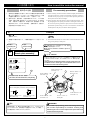
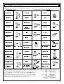
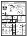
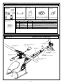
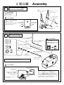
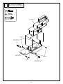

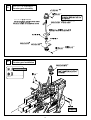
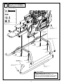
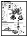
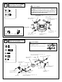
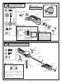
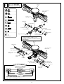
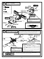
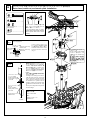
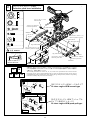
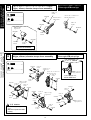
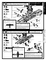
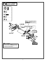
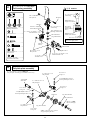
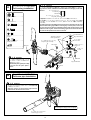
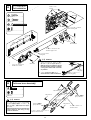
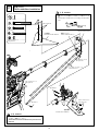
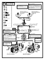
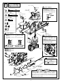

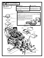
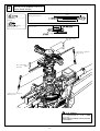
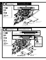
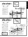
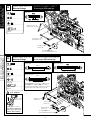

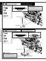
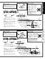
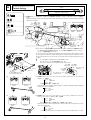
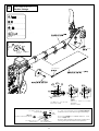

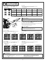
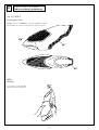
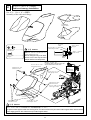
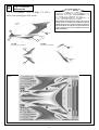
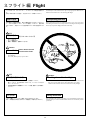
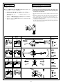
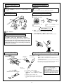
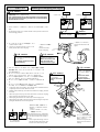
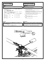
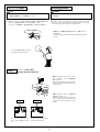
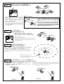
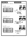
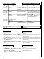
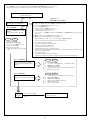
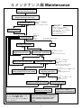
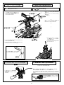
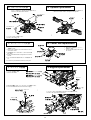
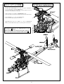
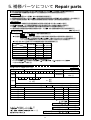
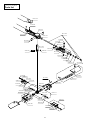
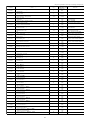
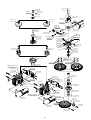
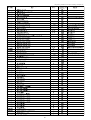
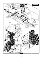

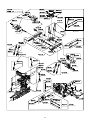
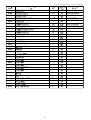
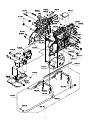
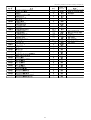
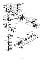
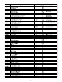
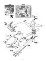
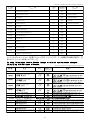
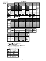
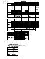
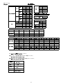
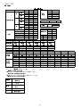
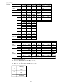
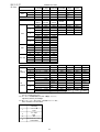
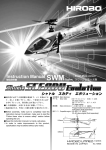
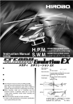

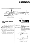
![Additional manual for Shuttle RG [M]](http://vs1.manualzilla.com/store/data/006567025_2-59f89030a71ead6ce0d591fb29588077-150x150.png)