1
Watt – MAS2000
Getriebemotoren
Betriebs- und Wartungsanleitung
LA-BA-MAS12-08-08
Wälz- und Gleitlager
Antriebstechnik
Lineartechnik
Betriebsanleitung für MAS - Getriebe und Getriebemotoren
Operating and maintenance manual for MAS - Gear units and geared motors
Inhaltsverzeichnis
Seite
1. Hinweise
1.1 Allgemeine Hinweise
1.2 Sicherheits- und Hinweiszeichen
1.3 Haftungsauschluss
Contents
Page
1. Information
3
3
3
1.1 General information
1.2 Safety and information markings
1.3 Exclusion of liability
3
3
3
2. Allg. Sicherheitshinweise, Transport
4
2. General safety information, transport
4
3. Checkliste - Getriebe
5
3. Check lists – Gear unit
5
4. Mechanische Installation
4.1
4.2
4.3
4.4
4.5
4.6
4.7
4.8
4.9
4.10
Lagerung
Inbetriebnahme - Vorarbeiten
Inbetriebnahme - Aufstellen des Getriebes
Getriebe mit Vollwelle
Montage u. Demont. Von Getrieben mit Hohlwelle
Montage und Demontage von Schrumpfscheiben
Montage von Abdeckkappe
Montage von Normmotoren an den IEC - Adapter
Montage von Servo-Motoren an Servo-Adapter
Montage von Drehmomentstützen
4. Mechanical installation
5
6
7
8
9
10
12
12
14
15
5. Inbetriebnahme
5.1 Ölstand des gelieferten Getriebes
5.2 Gehäuseoberflächentemperatur
5.3 Kontrolle des Getriebes
5
6
7
8
9
10
12
12
14
15
5. Startup
5.1 Oil level in the gear unit as delivered
5.2 Gear housing temperature
5.3 Inspecting the gear unit
18
19
6.1 Inspection and maintenance intervals
6.2 Inspection and maintenance work on gear u.
20
7.1 Malfunctions on the gear unit
17
17
17
6. Inspection and maintenance
7. Betriebsstörungen
7.1 Störungen am Getriebe
Bearing system
Startup - Preparatory work
Startup - Setting up the gear unit
Gear unit with solid shaft
Instal. And removal of hollow-shaft gear u.
Installation and removal of shrink disc
Installation and removal of protection cap
Instal. of stand. motors on the IEC adapters
Instal. of stand. Motors on SERVO adapters
Installation of torque arms
17
17
17
6. Inspektion und Wartung
6.1 Inspektions- und Wartungsintervalle
6.2 Inspektions- und Wartungsarbeiten Getriebe
4.1
4.2
4.3
4.4
4.5
4.6
4.7
4.8
4.9
4.10
18
19
7. Malfunctions
20
8. Tabelle für Schraubenanzugsmomente
20
8. Table of tightening torques
20
9. Schmierstoffe
21
9. Lubricants
21
10. Bauformen und Schmierstoffmengen
10.1
10.2
10.3
10.4
10.5
10.6
10.7
10.8
Stirnradgetriebe
Einstufige Stirnradgetriebe
Aufsteckgetriebe
Flachgetriebe
Kegelstirnradgetriebe
Kegelflachgetriebe
Stirnradschneckengetriebe
Ölstandskontrolle bei Getrieben mit
Ölstandsschraube in vertikaler Bauform
10. Mounting positions and lubric. capacity
22
23
24
25
26
27
28
29
11. Elektrischer Anschluss
11.1 Bestimmungsgemäße Verwendung der Motoren
11.2 Elektromagnetische Verträglichkeit
11.3 Sicherheitsinweise
Aufstellung des Motors
Anschlusskasten
Ausbrechöffnungen
Isolationswiderstand überprüfen
Anschluss des Erdungsleiters
14. Inbetriebnahme
14.1 Checkliste - Motor/Getriebemotor
15. Betrieb
Max Lamb GmbH & Co. KG - D-97076 Würzburg
Proper use of the motors
Electromagnetic compatibility
Safety information
22
23
24
25
26
27
28
29
30
30
30
12. Preperation for connecting the motor
31
31
31
32
33
12.1
12.2
12.3
12.4
12.5
34
13.1 Direction of rotation
34
35
14.1 Check lists – motor/Geared motor
13. Anschluss des Motors
13.1 Drehrichtung
Helical gear unit
Single stage helical gear unit
Shaft mounted gear unit
Parallel shaft gear unit
Helical bevel gear units
Angle parallel shaft gear unit
Helical worm gear unit
Oil level control of gear units with oil level
plug at vertical mounting position
11. Electrical connection
30
30
30
12. Vorbereitung Motoranschluss
12.1
12.2
12.3
12.4
12.5
10.1
10.2
10.3
10.4
10.5
10.6
10.7
10.8
Motor installation
Terminal box
Knockout openings
Checking the insulation resistance
Connecting the ground conductor
31
31
31
32
33
13. Connecting the motor
35
14. Startup
15. Operation
34
34
35
35
2
Betriebsanleitung für MAS - Getriebe und Getriebemotoren
Operating and maintenance manual for MAS - Gear units and geared motors
16. Optionale Zusatzeinrichtungen
16.1
16.2
16.3
16.4
16.5
16.6
16.7
15. Optional additional devices
Stillstandsheizung
Kondenswasserbohrung
Fremdlüfter
Temperaturwächter TH
Kaltleitertemperaturfühler TF
Bremse
Drehgeber
36
36
36
37
37
37
40
16.1
16.2
16.3
16.4
16.5
16.6
16.7
Anti-condensation heating
Condensation drain hole
Forced cooling
Temperature control TH
Thermistor protection TF
Brake
Encoder
36
36
36
37
37
37
40
17. Motorschaltbild
41
17. Motor circuit diagram
41
18. Watt Drive Partner
44
18. Watt Drive Partner
44
1. Hinweise
1. Information
1.1 Allgemeine Hinweise
1.1 General information
Die vorliegende Betriebsanleitung (BA) ist Bestandteil
der Getriebelieferung und muss bevor Sie mit dem
Getriebe arbeiten gelesen werden. Die Anweisungen
dieser BA sollten unbedingt eingehalten werden.
Bewahren Sie die BA in der Nähe des Getriebes auf.
These Operating Instructions (OI) are part of the gear
unit as supplied, and you must read them before you
work with the gear unit. The instructions in the OI must
be followed. Keep the OI close to the gear unit.
Note: We assume no liability for damages or disruptions
of operations resulting from the failure to observe this OI.
Hinweis: Für Schäden bzw. Betriebsstörungen, die durch
Nichtbeachtung dieser BA resultieren, wird keine Haftung
übernommen.
In order to develop the product further, Watt Drive
reserves the right to make modifications to the individual
components or assemblies that it believes to be useful to
improve the product, while maintaining its essential
characteristics.
Die Firma Watt Drive behält sich in Sinne einer
Weiterentwicklung das Recht vor, an den einzelnen
Bauteilen bzw. Baugruppen Änderungen vorzunehmen,
die unter Beibehaltung der wesentlichen Merkmale zur
Verbesserung des Produkts für sinnvoll erachtet werden.
Bestimmungsgemäße Verwendung:
Die Getriebe / Getriebemotoren sind für gewerbliche
Anlagen bestimmt und dürfen nur entsprechend den
Angaben in der technischen Dokumentation von Watt
Drive eingesetzt werden.
Use as intended:
The drive units / drive motors are intended for
commercial systems, and may only be used in
accordance with the information provided in the Watt
Drive technical documentation.
1.2 Sicherheits- und Hinweiszeichen
1.2 Safety and information markings
Diese Sicherheits- und Warnhinweise sind unbedingt zu
beachten!
All safety and warning instructions must be followed
without exception!
!!
S
A
Warnung vor elektrischer Gefahr, z.B. Bei Arbeiten
unter Spannung.
Warnung vor mechanischer Gefahr, z.B. Arbeiten
an Hubwerken.
Warnung vor mechanischer Gefahr, z.B. Arbeiten an
Hubwerken.
Wichtige
Anweisung
störungsfreien Betrieb.
für
sicheren
und
Warning of electrical danger, e.g. working with live
machines.
Warning of mechanical danger, e.g. working with
hoisting equipment.
!!
S
A
Warning of mechanical danger, e.g. working with
hoisting equipment.
Important
instructions
operation.
for
safe,
trouble-free
1.3 Haftungsausschluss
1.3 Exclusion of liability
Die Beachtung der BA ist Grundvoraussetzung für den
sicheren Betrieb des Getriebes/Getriebemotors und für
die Erreichung der angegebenen Produkt-eigenschaften
und Leistungsmerkmale. Für Personen-, Sach- oder
Vermögensschäden, die wegen Nichtbeachtung der BA
entstehen, übernimmt Watt Drive keine Haftung. Die
Sachmängelhaftung
ist
in
solchen
Fällen
ausgeschlossen.
You must comply with the information contained in these
OI to en-sure safe operation of the gear unit, geared
motor and to achieve the specified product characteristics and performance requirements. Watt Drive
assumes no liability for in-jury to persons or damage to
equipment or property resulting from non-observance oft
hese OI. In such cases, any liability for defects is
excluded.
Max Lamb GmbH & Co. KG - D-97076 Würzburg
3
Betriebsanleitung für MAS - Getriebe und Getriebemotoren
Operating and maintenance manual for MAS - Gear units and geared motors
2. Allgemeine Sicherheitshinweise, Transport
Die
Lieferung
ist
nach
Erhalt
auf
etwaige
Transportschäden zu untersuchen. Die Inbetriebnahme
ist gegebenenfalls auszuschließen.
Der Kunde ist verantwortlich für die fachgerechte
Aufstellung des Antriebes.
Bestätigte Eigenschaften der Antriebe sowie die
Erfüllung eventueller Garantieansprüche bedingen die
Einhaltung der Hinweise in dieser Betriebsanleitung.
Achten Sie darauf, niemals beschädigte Produkte in
Betrieb zu nehmen!
Lesen Sie die Betriebsanleitung sorgfältig, bevor Sie mit
Aufstell-, Montage- oder Wartungsarbeiten beginnen.
Die verwendeten Ringschrauben (im Lieferungumfang ab
Getriebebaugröße 110 enthalten) entsprechen der DIN
580, die darin enthaltenen Vorschriften sind einzuhalten.
Die Ringschrauben müßen fest angezogen sein. Sie sind
nur für das Eigengewicht des Getriebes bzw.
Getriebemotors ausgelegt.
Es dürfen keine zusätzlichen Lasten angebracht werden.
Gewinde
m [kg]
M8 M10 M12 M16 M20 M24 M30
140 230 340 700 1200 1800 3600
Die Masse m [kg] entspricht
der maximal
anzuhängenden Last bei Zug in Richtung F der
Schraubenachse.
Die Montage, Inbetriebnahme sowie Wartungs- und
Reparaturarbeiten am Getriebe/Getriebemotor sowie an
der elektrischen Zusatzausstattung dürfen nur von
qualifiziertem Fachpersonal ausgeführt werden, unter
Berücksichtigung folgender Punkte:
• Betriebsanleitung
• Hinweisschilder am Getriebe/Getriebemotor
• aller
anderen
zum
Antrieb
gehörenden
Projektierungsunterlagen, Inbetriebnahmeanleitungen
• Anlagenspezifische Bestimmungen und Erfordernisse
• aktuell
gültigen
nationalen
und
regionalen
Vorschriften über Sicherheit und Unfallverhütung.
Montage- und Wartungsarbeiten sind nur bei
stillstehendem Getriebe durchzuführen. Der Antrieb
muss spannungsfrei und gegen versehentliches
Einschalten abgesichert sein.
Der Betrieb des Getriebes mittels Frequenzumrichter
darf nur unter Einhaltung der Angaben am Typenschild
des Getriebes durchgeführt werden.
Max Lamb GmbH & Co. KG - D-97076 Würzburg
2. General safety information, transport
After being delivered, the unit must be inspected for any
damage that may have occurred during transport. If the
unit's condition warrants, it may be necessary to take
action to prevent the unit from being put into operation.
The customer is responsible for setting up the drive in
accordance with good engineering practices.
The instructions in these Operation Instructions must be
followed to achieve the confirmed characteristics of the
drive units and if any warranty claims are to be met.
Make certain that you never put damaged products into
operation!
Read these Operating Instructions carefully before you
begin any setup, installation, or maintenance work.
The ring bolts that are used (contained in the items
supplied beginning with gear unit size 110) comply with
DIN 580; the requirements contained therein must be
observed.
The ring bolts must be securely tightened. They are
designed to hold the gear unit's own weight and that of
the gear motor.
No additional loads may be applied.
Thread
m [kg]
M8 M10 M12 M16 M20 M24 M30
140 230 340 700 1200 1800 3600
The mass m [kg] corresponds to the maximum
dependent load in tension in direction F of the bolt axis.
Installation, startup, maintenance and repair work on the
gear unit / gear motor as well as on electrical accessory
equipment may only be performed by qualified technical
personnel, taking the following items into account:
• Operating Instructions
• Information labels/tags on the gear unit / geared
motor
• All other project documents, setup manuals,
operating manuals
• Drive-specific specifications and requirements
belonging to the drive unit
• the applicable regional and national regulations on
safety and accident prevention.
Installation and maintenance work may only be
performed when the gear units are shut down. There
must be no load on the drive and steps must be taken to
prevent units from being actually turned on.
Operation of the drive unit by means of a frequency
inverter may only occur if the specifications shown on the
drive unit nameplate have been carried out.
4
Betriebsanleitung für MAS - Getriebe und Getriebemotoren
Operating and maintenance manual for MAS - Gear units and geared motors
3. Checkliste - Getriebe
Vor Inbetriebnahme des Getriebes ist zu überprüfen:
3. Check lists - Getriebe
Check the following before starting up the gear unit:
Informationen
siehe Kapitel
Untersuchen Sie die Lieferung sofort nach Erhalt auf etwaige
Die Inbetriebnahme ist ggf. nicht durchzuführen.
Entspricht die Bauform auf dem Typenschild der tatsächlichen Einbaulage?
Ist das Entlüftungsventil an der richtigen Stelle (der Bauform entsprechend)?
Vor der Inbetriebnahme ist die Transportsicherung zu entfernen.
Wurde bei einer Schrumpfscheibenausführung die Verbindung geprüft?
Sind alle Entlüftungsschrauben und -ventile frei zugänglich?
Transportschäden.
2
10
10
4.3
4.6
Informations
see chapter
Inspect the shipment immediately after it has been received for any transport damages.
In some cases it may not be advisable to start up the unit.
Does the mounting position on the nameplate correspond to the actual mounting position?
Is the vent plug located at the correct location (in compliance with the installation position)?
Please remove the transportation lock on the breather plug before usage.
In the case of a shrink disc version: has the expansion been checked?
Are all bleed screws and valves freely accessible?
Checkliste
vor
Inbetriebnahme
des
Motors/
Getriebemotors siehe Kapitel 14.1 dieser BA,
Seite 35.
4. Mechanische Installation
4.1 Lagerung
Geprüft
checked
2
10
10
4.3
4.6
Check list before starting up the motor (geared
motor) see in this OI chapter 14.1, page 35.
4. Mechanical installation
4.1 Bearing system
Bei der Lagerung der Getriebe sind folgende Punkte zu
beachten:
The following items must be taken into account when
storing the gear units:
Allgemeines:
Die Lagerung von Antriebseinheiten hat generell in
geschlossenen Räumen zu erfolgen.
General:
In general, the storage of drive units must be done in
closed rooms.
Umgebungstemperatur max. 25°C (77°F)
Ambient temperature max. 25°C (77°F)
Relative Luftfeuchtigkeit max. 80%
Relative humidity max. 80%
Die Antriebseinheiten sind vor Sonneneinstrahlung bzw.
UV - Licht zu schützen.
The drive units are to be protected from exposure to the
sun or UV light.
Es dürfen keine aggressiven und korrosiven Stoffe in der
Umgebung gelagert werden.
No aggressive or corrosive materials are to be stored in
the vicinity of the unit.
Die Lagerung der Getriebe hat in der für die spätere
Verwendung vorgesehene Einbaulage zu erfolgen.
Die Getriebe sind alle 6 Monate abtriebsseitig um 1-2
Umdrehungen zu drehen, um eine Benetzung der
Innenbauteile mit Schmierstoff zu gewährleisten.
The gear units are to be stored in the same position that
is intended for a later use.
The gear units are to be rotated 1-2 revolutions on the
output side every 6 months to ensure that the interior
parts are wetted with lubricant.
Die Einheiten sind vor mechanischer Belastung &
Krafteinwirkung von aussen zu schützen.
The units are to be protected from mechanical loads and
exposure to outside forces.
Max Lamb GmbH & Co. KG - D-97076 Würzburg
5
Betriebsanleitung für MAS - Getriebe und Getriebemotoren
Operating and maintenance manual for MAS - Gear units and geared motors
Langzeitlagerung:
Long-term storage:
Bei längerer Lagerdauer als 12 Monate sind die Getriebe
komplett mit dem Schmiermittel laut Typenschild bzw.
Ölschild zu befüllen.
Die
außenliegenden
blanken
Teile
sind
mit
Korrosionsschutzmittel
zu
konservieren
(eine
halbjährliche Kontrolle ist empfehlenswert). Nach einem
Jahr ist der Korrosionsschutz zu erneuern.
Vor Inbetriebnahme ist das Schmiermittel des Getriebes
abzulassen. Falls mehrere Ölräume vorhanden sind, gilt,
dass alle Ölräume entleert werden müssen.
When the gear units are to be stored for longer than
12 months, they must be completely filled with lubricant
per the nameplate or lubricant plate.
Unfinished, bare-metal parts on the outside of the unit
are to be protected with a corrosion protection product
(inspection every 6 months is recommended). The
corrosion protection must be replaced after one year.
Before starting the gear unit, drain the lubricant from it. If
more than one lubricant chamber is present, make
certain that all of the lubricant chambers have been
drained out.
Die Dichtungen setzen sich bei längerer Standzeit. Vor
Inbetriebnahme sind die Schrauben nachzuziehen.
Gasket settles, especially after a longer period without
loading. Before starting the screws must be retightening.
Anschließend ist das Getriebe mit der am Typenschild
spezifizierten Schmiermitteltype und angegebenen
Schmiermittelmenge zu befüllen.
Then fill the gear unit with the lubricant type specified on
the nameplate using the specified quantity of lubricant.
Bei längerer Lagerung als 24 Monate sind vor der
Inbetriebnahme die Getriebe auf Dichtheit zu überprüfen.
Bei eventuellen sichtbaren Rissen an der Oberfläche der
Dichtelemente sind diese zu ersetzen.
If the gear units are stored for longer than 24 months
before being put into service, they must be checked for
leaks. If there are any visible cracks on the surfaces of
sealing elements, such parts must be replaced.
4.2 Vorarbeiten
4.2 Preparatory work
Prüfung des Getriebes:
Inspecting the gear unit:
Das Getriebe darf nur dann in Betrieb genommen
werden, wenn:
The gear unit must not be put into operation unless:
The information on the gear unit specifications plate
matches the permissible local usage conditions.
die Angaben auf dem Leistungsschild des Getriebes mit
dem
zulässigen
Einsatzbedingungen
vor
Ort
übereinstimmen.
No damage caused, for example, by storage or transport,
is apparent.
keine Beschädigungen, z.B. durch Lagerung oder
Transport erkennbar sind.
and in particular, the shaft seals, cover caps, and guard
hoods are not damaged.
Insbesondere die Wellendichtringe, Verschlusskappen
und Abdeckhauben nicht beschädigt sind.
No leaks or loss of oil are visible.
keine Undichtigkeit bzw. kein Ölverlust sichtbar ist.
keine Korrosion oder andere Hinweise auf
unsachgemäße oder feuchte Lagerung hinweisen.
No corrosion or other indication of improper storage or
storage under damp conditions is present.
eine
All of the packaging materials were removed.
das Verpackungsmaterial restlos entfernt wurde.
A
Grunsätzlich sind Abtriebswellen und Flanschflächen
gründlich
von
Korrosionsschutzmittel
oder
Verschmutzungen
zu
befreien,
dabei
können
handeslübliche Lösungsmittel verwendet werden.
WICHTIG:
Die Dichtlippen der Wellendichtringe dürfen nicht mit
dem Lösungsmittel in Kontakt treten
→ Materialschäden möglich!
Max Lamb GmbH & Co. KG - D-97076 Würzburg
As a general rule, drive shafts and flange surfaces must
have all corrosion protection products and dirt cleaned
from them, standard commercial solvents can be used.
A
IMPORTANT: The sealing lips on the shaft seals must
not be allowed to come in contact with the solvent.
→ Material can be damaged!
6
Betriebsanleitung für MAS - Getriebe und Getriebemotoren
Operating and maintenance manual for MAS - Gear units and geared motors
Check the mounting position:
Prüfung der Bauform:
A
A
Das Getriebe darf nur in der angegebenen Bauform
betrieben werden, welche dem Typenschild zu
entnehmen ist. Die Einbaulage darf sich im Betrieb nicht
verändern.
Antriebe, welche ohne Ölfüllung bestellt werden,
kommen mit Innenkonservierung zur Auslieferung. Die
Innenkonservierung
der
Getriebe
erfolgt
mit
Korrosionsschutzöl. Das Konservierungsöl ist auf jeden
Fall mit der am Typenschild angegebenen Öltype
mischbar, sodaß die Getriebe vor der Befüllung nicht
ausgespült werden müssen.
A
The gear unit may only be operated in the specified
mounting position, which may be found on the
nameplate. The mounting position must not change
during operation.
Gear units that are ordered without oil filling are supplied
with internal rust proofing consisting of anti-corrosion oil.
The anti-corrosion oil can however be mixed with the
recommended lubricant indicated on the nameplate. This
means that the unit does not have to be flushed before
filling with oil.
Lackieren des Getriebes:
Painting the gear unit:
Wenn der Antrieb überlackiert bzw. teilweise nachlackiert
wird, so ist darauf zu achten, dass das Entlüftungsventil
und die Wellendichtringe sorgfältig abgeklebt werden.
Nach Fertigstellung der Lackierarbeiten sind die
Klebestreifen zu entfernen.
If the gear unit will be painted or partially repainted, make
certain that the vent plug and the shaft seals are carefully
masked. Remove the masking tape after the painting
work is completed.
Um unzulässige Erwärmung des Getriebes
verhindern ist folgendes zu beachten:
zu
A
In order to prevent access heating of the gear unit,
the following must be observed:
Um das Getriebe muss ausreichend Freiraum vorhanden
sein.
Die Kühlluft bei Getriebemotoren muss das Getriebe
ungehindert umströmen können.
Sufficient clearance must be provided around the gear
unit.
The cooling air for gear unit motors must be able to flow
unhindered around the gear unit.
Das Getriebe darf nicht vollkommen eingehaust werden.
The gear unit must not be completely boxed in with a
housing.
Die Getriebe dürfen nicht von anderen Aggregaten mit
warmer Abluft beströmt werden.
Es darf keine Wärme in das Getriebe eingeleitet werden
(z.B. Fundament)
The gear units must not be exposed to hot exhaust air
from other units.
No heat must be transferred into the gear unit (for
example from the foundation).
4.3 Aufstellen des Getriebes
4.3 Setting up the gear unit
Die Aufstellung soll so erfolgen, daß der Antrieb keinen
Schwingungen oder Erschütterungen ausgesetzt ist, um
dadurch bedingte Geräuschentwicklung zu vermeiden.
When installing please ensure that the unit is not
exposed to any shocks or vibrations in order to avoid
noise during operation.
Die Befestigungsfläche muß eben und verwindungssteif
sein.
Gehäuseverspannungen sind unbedingt zu vermeiden.
The mounting surface should be even and torsionally
rigid.
Distortion of the gear case should also be avoided.
Das Reaktionsmoment ist mit einer Drehmomentstütze
oder einem Gummipufferset abzufangen (keine starren
Verschraubungen).
Reduce reaction torque with a torque arm or a rubber
buffer kit (no rigid joints).
Max Lamb GmbH & Co. KG - D-97076 Würzburg
7
Betriebsanleitung für MAS - Getriebe und Getriebemotoren
Operating and maintenance manual for MAS - Gear units and geared motors
A
Getriebeentlüftung:
A
Ölablassschrauben sowie Entlüftungsventile müssen frei
zugänglich sein!
Bleeding the gear unit:
Oil drain plugs and vent plugs must be fully accessible!
Gear unit with vent plug:
Getriebe mit Entlüftungsschraube:
The vent plug with transport locking device is installed
at the proper position for the mounting position.
The rubber strip must be completely torn off before the
unit is put into operation.
Die Entlüftungsschraube mit Transportsicherung ist
an der der Bauform entsprechenden Position
angebracht.
Die Gummilasche ist vor der Inbetriebnahme komplett
abzureißen.
Das Entlüftungsventil ist vor Inbetriebnahme zu
aktivieren, indem die Transportsicherung wie folgend
beschrieben komplett entfernt wird:
The vent plug is to be activated before the unit is put
into operation by completely removing the transport
protection as described below:
Information label (red)
Hinweisschild (rot)
S
S
S
Getriebe ohne Entlüftungsschraube:
Gear drives lacking a vent plug:
Getriebe in geschlossener Ausführung werden ohne
Entlüftungsventil geliefert.
Sealed-design gear drives are supplied without a vent
plug.
Dies gilt für folgende Getriebetypen:
H. 40E,A,S; H. 50E,A,S,C; H. 55A,S,C; H. 60E,A,S,C;
H. 65A,C
A.. 46A; A.. 56A,S,C; A.. 66A,S,C
F.. 55A,S,C; F.. 65A,S,C
K.. 40A; K.. 50A,C; K.. 60A,C
This applies to the following gear unit types:
H. 40E,A,S; H. 50E,A,S,C; H. 55A,S,C; H. 60E,A,S,C;
H. 65A,C
A.. 46A; A.. 56A,S,C; A.. 66A,S,C
F.. 55A,S,C; F.. 65A,S,C
K.. 40A; K.. 50A,C; K.. 60A,C
4.4 Getriebe mit Vollwelle
4.4 Gear unit with solid shaft
Alle Abtriebswellen sind bei Lieferung mit einem
Konservierungsmittel versehen, der mit einem üblichen
Lösungsmittel zu entfernen ist.
All output shafts are provided with a corrosion protection
product upon delivery. This product must be removed
with a conventional solvent.
! Achtung !
Das Lösungsmittel darf nicht an die Dichtlippen der
Wellendichtringe kommen!
Die Abtriebswellen sind bis zu einem Durchmesser von
50mm nach Toleranzfeld ISO k6 und ab 55mm nach
Toleranzfeld ISO m6 gefertigt.
Alle Abtriebswellen sind mit Zentriergewinden nach DIN
332
versehen,
die
zum
Aufziehen
von
Übertragungselementen benutzt werden sollten.
! Achtung !
Schläge und Stöße auf das Wellenende unbedingt
vermeiden, da die Abtriebslagerung dadurch beschädigt
werden kann.
! Achtung !
Mech. Antriebselemente die Radialkräfte auf die
Abtriebswelle ausüben sind möglichst nah dem
Abtriebslagern zu montieren!
Aufgesetzte Übertragungselemente sollten gewuchtet
sein und dürfen keine unzulässigen Radial- oder
Axialkräfte hervorrufen (zulässige Werte siehe Katalog).
Max Lamb GmbH & Co. KG - D-97076 Würzburg
S
S
S
! Important !
The solvent must not be allowed to come into contact
with the shaft seals!
The output shafts are manufactured with a diameter of
50 mm in ISO k6 tolerance class and beginning at a
diameter 55 mm in ISO m6 tolerance class.
All output shafts are equipped with DIN 332 tapped
center holes that are used to tighten the transfer
elements.
! Important !
Make certain to prevent all impacts and mechanical
shocks on the end of the shaft since the output bearing
system can be damaged.
! Important !
Mechaincal drive elements that apply radial forces to the
output shaft must be installed as close as possible to the
output shaft bearings!
Add-on power transfer elements should balance and
must not cause any unacceptable radial or axial forces
(see Catalogue for acceptable values).
8
Betriebsanleitung für MAS - Getriebe und Getriebemotoren
Operating and maintenance manual for MAS - Gear units and geared motors
4.5 Montage und Demontage von Getrieben mit
Hohlwelle
4.5.1 Montage
4.5 Installation and removal of hollow-shaft
gear units
4.5.1 Assembling
Die kundenseitige Maschinenwelle ist vor der Montage
des Hohlwellengetriebes sorgfältig zu reinigen und auf
eventuelle
Schäden
wie
z.B.
Kerben
oder
Aufstauchungen zu prüfen.
Vor dem Aufziehen des Hohlwellengetriebes auf die
Maschinenwelle, ist die Oberfläche der Maschinenwelle
mit Schmierpaste
(Bild 1) wie z.B. Klüber-Paste
46MR401 einzustreichen.
The customer-side machine shaft must be carefully
cleaned and checked for any damage such as grooves
or compressed areas before the hollow-shaft gear unit is
installed.
Before tightening the hallow-shaft gear unit onto the
machine shaft, paint the surface of the machine shaft
with lubricating paste (Figure 1) such as Klüber Paste
46MR401.
Die Montage von Hohlwellengetrieben hat grundsätzlich
so zu erfolgen, dass keine axialen Kräfte auf die
Abtriebswellenlagerung entstehen.
The hollow-shaft gear units must always be installed in
such a way that no axial forces are applied to the output
shaft bearing system.
Gewindestange +Sechskantmutter
Threaded rod + hex nut
Befestigungset (optional)
Fixing kit (optional)
Druckscheibe
Thrust washer
Bild 1: Aufziehen der Kundenwelle ohne
oder mit Anlageschulter
Fig. 1: Tightening the customer shaft
with or without shoulder
Distanzrohr nicht im Lieferumfang
Spacer tube not included in items supplied
Bild 2: Kundenwelle-Befestigung
mittels WATT-Befestigungsset
ohne Anlageschulter
Fig. 2: Mounting the customer shaft
using a WATT mounting set
without a shoulder
Montage:
Getriebe mit Hohlwelle auf die Maschinenwelle (Bild 1)
aufziehen. Distanzring Pos. 10 bei Kundenwelle ohne
Anlageschulter, Sicherungsring Pos. 3 und Scheibe Pos.
2 in die Hohlwelle einsetzen und mit Schraube Pos.4
fixieren.
Schrauben-Anzugsmoment siehe Kap. 8 auf der Seite
20.
Max Lamb GmbH & Co. KG - D-97076 Würzburg
Bild 3: Kundenwelle-Befestigung
mittels WATT- Befestigungsset
mit Anlageschulter
Fig. 3: Mounting the customer shaft
using a WATT mounting set
with a shoulder
Installation:
Draw the gear unit with hollow shaft onto the machine
shaft (Fig. 1). Insert the spacer ring, item 10, with there is
a customer shaft without a shoulder, the circlip, item 3,
and washer, item 2, into the hollow shaft and attach
using the bolt, item 4.
See section 8 on page 20 for the bolt tightening torque.
9
Betriebsanleitung für MAS - Getriebe und Getriebemotoren
Operating and maintenance manual for MAS - Gear units and geared motors
4.5.2 Demontage
4.5.2 Assembling
Bild 5: Demontage der Kundenwelle
mit oder ohne Anlageschulter
Fig. 5: Removing the customer shaft
with or without shoulder
1)
2)
3)
4)
1)
2)
3)
4)
Hohlwelle
Scheibe
Sicherungsring DIN 472
Zylinderschraube DIN 6912 (kundenbezogen,
Länge der Schraube entsprechend der
Maschinenwellenlänge)
5) Kundenwelle mit Zentriergewinde nach DIN332,
Bl.2 Form DR
6) Druckscheibe
7) Abdrückmutter
8) Abdrückschraube
9) Zylinderschraube DIN 6912 (Inhalt des
Befestigungssets für die WATT-Einsteckwelle)
10) Distanzrohr (nur bei Maschinenwellen ohne
Anlageschulter)
Demontage:
Lösen der Befestigungsschraube Pos. 4,9. Entfernen Sie
das komplette WATT-Befestigungset. Druckscheibe Pos.
6 und Abdrückmutter Pos.7 in die Hohlwelle geben,
Sicherungsring einsetzen und mit Abdrückschraube
Pos.8 das Getriebe von der Welle abdrücken.
Die Teile 4, 6, 7, 8 und 10 sind nicht im Lieferumfang
enthalten. Teile 2, 3 und 9 sind im Befestigungsset
GMBSBSD . . . enthalten.
5)
6)
7)
8)
9)
10)
Hollow shaft
Disc
Circlip DIN 472
Socket head screw DIN 6912 (to customer
specification, length according to machine shaft
length)
Customer's shaft °)
Thrust washer
Jack nut
Jack screw
Socket head screw DIN 6912 (part of fixing kit for
WATT insert shaft)
Spacer tube (only with machine shafts without
shoulders)
Removal:
Remove the screw (4), disc (2) and circlip (3), place the
thrust washer (6) and jack nut (7) in the hollow shaft,
insert the circlip and remove the gear unit from the shaft
with jack screw (8).
Parts 4, 6, 7, 8 and 10 are not supplied with the gear
unit. Parts 2, 3 and 9 are included in fixing kit GMBSBSD
......
4.6 Montage und Demontage von
Schrumpfscheiben
4.6.1 Montage:
4.6 Installation and removal of shrink disks
Die Schrumpfscheiben werden einbaufertig geliefert.
Diese dürfen nicht vor dem erstmaligen Einbau zerlegt
werden.
The shrink discs are supplied ready to install. They must
not be taken apart prior to the first installation.
Maschinenwelle
Machine shaft
Aussenring
Outer ring
4.6.1 Installation:
Spannschrauben
Locking bolts
Innenring
Inner ring
Anzugsmoment für Spannschrauben
Tightening torque of the bolts
Dreiteilige Schrumpfscheibe
Three-part shrink disk
Hohlwelle
Hollow shaft
Max Lamb GmbH & Co. KG - D-97076 Würzburg
Zweiteilige Schrumpfscheibe
Two-part shrink disk
10
Betriebsanleitung für MAS - Getriebe und Getriebemotoren
Operating and maintenance manual for MAS - Gear units and geared motors
1. Sorgfältiges entfetten der kompletten
Hohlwellenbohrung
→ muß ABSOLUT fettfrei sein!
2. Maschinenwelle im Klemmbereich der Schrumpfscheibe sorgfältig entfetten.
→ muß ABSOLUT fettfrei sein!
3. Aufschieben der Schrumpfscheibe auf die Hohlwelle.
Bereich des Schrumpfscheiben-Sitzes kann die
Außenfläche der Hohlwelle gefettet werden.
S
! ACHTUNG !
SPANNSCHRAUBEN NICHT ANZIEHEN BEVOR DIE
WELLE EINGEBAUT IST!
1. Carefully degrease the complete hollow-shaft hole.
→ must be ABSOLUTELY free of grease!
2. Degrease the machine shaft in the area that the
shrink disc clamps to.
→ must be ABSOLUTELY ree of grease!
3. Slip the shrink disk onto the hollow shaft. The outer
surface of the hollow shaft may be greased in the area
of the shrink disk seat.
S
! WARNING !
NEVER TIGHTEN THE LOCKING BOLTS BEFORE
SHAFT INSTALLATION!
3. Push the hollow shaft onto the machine shaft.
4. Tighten all the locking bolts uniformly and in the right
sequence (see figure).
4. Aufschieben der Hohlwelle auf die Maschinenwelle.
5. Anziehen aller Spannschrauben gleichmäßig und der
Reihe nach (siehe nachfolgende Abbildung).
Abdrückgewinde
Jack nut
Tighten all the bolts successively several times until they
display the required tightening torque. Check with a
torque wrench.
Tightening torque of the bolts -> see lettering on the
shrink disc.
Es sind mehrere Umläufe nötig, bis alle Schrauben das
erforderliche
Anzugsmoment
aufweisen.
Das
Anzugsmoment muß mit einem Drehmomentschlüssel
geprüft werden. → siehe Beschriftung auf der
Schrumpscheibe.
S
Die Spannschraubenanzahl hängt von der Schrumpfscheibenbaugröße ab!
! IMPORTANT!
DO NOT TIGHTEN THE BOLTS IN DIAGONALLY
OPPOSITE SEQUENCE!
The number of locking bolts depends on the size of the
shrink disks!
TIPP:
Nach erfolgter Montage ist die Hohlwelle bzw. die
Maschinenwelle stirnseitig mit einem Strich (Stift) zu
kennzeichnen, um ein Durchrutschen während der
Inbetriebnahme (unter Last) zu erkennen.
TIP:
After installation you can sign the hollow shaft
respectively the machine shaft with a stroke (use a
pencil) to detect a slipping during the initial operation
(under load).
4.6.2 Demontage:
4.6.2 Removal:
Der Lösevorgang ist ähnlich dem des Verspannens.
The procedure is similar to installation, but in reverse
order.
! ACHTUNG !
SCHRAUBEN NICHT "ÜBER KREUZ" ANZIEHEN!
1. Lösen der Spannschrauben, gleichmäßig und der
Reihe nach. Jede Spannschraube darf anfangs pro
Umlauf nur
etwa eine Viertel-Umdrehung gelöst
werden. Die Spannschrauben nie ganz herausdrehen.
2. Abdrücken des Innenringes mit Hilfe der Abdrückgewinde. Rostansatz, der sich auf der Maschinenwelle
vor der Hohlwelle gebildet haben könnte, muß zuvor
entfernt werden.
3. Ausbau der Maschinenwelle bzw. Abziehen der
Hohlwelle von der Maschinenwelle.
Schritt 2 nur bei zweiteiliger Schrumpfscheibenausführung !
Max Lamb GmbH & Co. KG - D-97076 Würzburg
S
1. Undo the locking bolts uniformly and in sequence.
Only undo each locking bolt about a quarter turn
initially. Do not remove the locking bolts completely.
2. Press the inner ring off using the jack nut.
Remove any rust beforehand that may have formed
on the machine shaft in front of the hollow shaft.
3. Remove the machine shaft and then slip the hollow
shaft off the machine shaft.
Step 2 only required for two-part shrink disk !
11
Betriebsanleitung für MAS - Getriebe und Getriebemotoren
Operating and maintenance manual for MAS - Gear units and geared motors
4.7 Montage von Abdeckkappe
S
4.7 Installation and removal of protection cap
Abdeckhauben
sind
vor
der
Montage
auf
Transportschäden
zu
untersuchen.
Beschädigte
Abdeckhauben dürfen nicht verbaut werden, da sie
möglicherweise schleifen können.
Alle Befestigungsschrauben sind zu verwenden und
durch Benetzung mit Sicherungsklebstoff (mittelfest), zu
sichern. Schrauben-Anzugsmoment siehe Kap. 8 auf der
Seite 20.
S
Before being installed, the cover guards must be
inspected for any damage that might have occurred
during transport. Damaged cover guards must not be
installed, since they can possibly cause abrasion.
All of the fixing bolts are to be used and secured by
wetting them with a thread-locking adhesive (medium
strength). See section 8 on page 20 for the bolt
tightening torque.
O-Ring bei den Getriebetypen
O-Ring with gear unit types
K.. 40. - K.. 110.
S.. 404. - S.. 609.
Bild 1: Hohlwellen-Abdeckkappe
Fig. 1: Protection cap for hollow shaft
Bild 2: Schrumpfscheiben-Abdeckkappe
Fig. 2: Protection cap for shrink disc
4.8 Montage von Normmotoren (IEC 60072,
DIN EN 50347) an den IEC-Adapter
4.8 Installation of standard motors (IEC 60072,
DIN EN 50347) on the IEC adapters
Watt Drive liefert IEC Adapter der Baugrößen 100/112,
132, 160, 180 mit einer integrierten spielfreien
Klauenkupplung aus. Die IEC – Adapter sind öldicht
ausgeführt, die Abdichtung der Schnittstelle erfolgt
zwischen Getriebe und Adapter.
Watt Drive supplies IEC adapters in sizes 100/112, 132,
160, 180 with an integrated, play-free claw coupling. The
IEC adapters have an oil-tight design, with the interface
being sealed between the gears and the adapter.
Montageablauf eines IEC-Normmotors (IEC 60072,
DIN EN 50347) an den IEC-Adapter IA63, IA71, IA80,
IA90, IA200 und IA225:
1. Die Motorwelle und die Flanschflächen von Motor und
Adapter sind zu reinigen und auf Beschädigungen zu
prüfen.
2. Die Motorwelle ist vor der Montage mit Schmierpaste
wie z.B. Klüberpaste 46 MR 401 zu benetzen.
3. Die Befestigungsschrauben (1) sind mit Sicherungsklebstoff (mittelfest) zu benetzen.
4. Der Motor wird danach auf den Adapter aufgesetzt
und die Schrauben (1) (nicht im Lieferumfang) mit
dem entsprechenden Moment angezogen.
Schrauben mit einer Mindestfestigkeit 8.8 verwenden.
Schrauben-Anzugsmomente siehe Kap. 8 Seite 20.
Assembly procedure for IEC standard motor(IEC
60072, DIN EN 50347) on the IEC Adapter IA63,
Bild 1: Prinzipdarstellung Montage Normmotor an IECAdapter
Fig. 1: Exposition for assembling standard motors on an
IEC adapter
Max Lamb GmbH & Co. KG - D-97076 Würzburg
IA71, IA80, IA90, IA200 und IA225:
1. Clean the motor shaft and the flange surfaces of the
motor and adapter and check for damage.
2. Before installing, wet the motor shaft with lubrication
paste, such as Klüber Paste 46 MR 401.
3. Wet the fixing screws (1) with thread-locking adhesive
(medium strength).
4. Then place the motor on the adapter and tighten the
bolts (1) (not included) to the specified torque.
Use bolts with minimum property class 8.8
See section 8 on page 20 for the bolt tightening
torque.
12
Betriebsanleitung für MAS - Getriebe und Getriebemotoren
Operating and maintenance manual for MAS - Gear units and geared motors
S
Montageablauf eines IEC - Normmotors an den IEC –
Adapter IAK100, IAK112, IAK132, IAK160 und
IAK180:
Assembly procedure for IEC standard motor on the
IEC adapter IAK100, IAK112, IAK132, IAK160 and
IAK180:
Bei der Montage der mitgelieferten Kupplungshälfte auf
die Motorwelle ist auf die richtige Einbaulage zu achten.
Die Kupplungshälfte ist dabei bündig auf die Motorwelle
zu montieren (siehe Bild 2, Seite 13).
The correct assembly position must be observed when
fitting the half coupling supplied onto the motor shaft.
The half coupling should be fitted flush to the motor shaft
(see figure 2 on page 13).
1. Entfernen Sie die Abdeckung des Adapters (1) und
entnehmen Sie die beiliegende Kupplungshälfte (3).
2. Die Motorwelle (2) und die Flanschflächen von Motor
und Adapter reinigen.
3. Kupplungshälfte (3) auf ca. 80°C (176°F) erwärmen
und auf Motorwelle montieren.
4. Die Kupplungshälfte wird dabei bündig Wellenspiegel
mit Ende der Bohrung montiert (siehe Bild!).
5. Sichern Sie die Passfeder (4) und die montierte
Kupplungshälfte mittels Gewindestift (5) mit dem
angegebenen Anzugsdrehmoment TA (M5 ! ca.
2,5Nm,M8 !ca. 10Nm). Verwenden Sie dazu
Schraubensicherungsmittel „mittelfest“.
6. Kontrollieren
Sie
den
korrekten
Sitz
der
Kupplungshälfte.
7. Die Kontaktfläche zwischen Motor und Adapter ist mit
geeignetem Dichtmittel abzudichten (gilt nur bei
Anbau von Motoren nach ATEX)
8. Montieren Sie den Motor an den Adapter, die
Kupplungsklauen
müssen
beidseitig
in
den
Kupplungsstern (6) eingreifen.
9. Befestigen Sie den Motor mit den geeigneten
Befestigungsschrauben (nicht im Lieferumfang) am
Adapter. Schrauben-Anzugsmoment siehe Kap. 8 auf
der Seite 20. Festigkeitsklasse mindestens 8.8.
1. Remove the adapter cover (1) and remove the half
Bild 2: Montage eines IEC – Motors an eine
Kupplungsadapter (IAK)
Fig. 2: Installing an IEC motor on the coupling adapter
(IAK)
! ACHTUNG !
Bei selbständig durchgeführter Ritzelmontage (7) ist vor
Montage des Wellendichtringes (8) das getriebeseitige
Lager (9) mit der unten angegebenen Fettmenge zu
füllen.
Adapterbaugröße IAK
Size of adapter (IAK)
100/112
132
160/180
Max Lamb GmbH & Co. KG - D-97076 Würzburg
coupling provided (3).
2. Clean the motor shaft (2) and the flange surfaces on
the motor and adapter.
3. Heat the half coupling (3) to approx. 80°C (176°F)
and fit onto the motor shaft.
4. The half coupling is fitted flush to the shaft panel with
the end of the bore hole (see diagram!).
5. Secure the key (4) and the fitted half coupling using a
set pin (5) using the specified tightening torque TA
(M5 ! approx. 2.5Nm, M8 ! approx. 10Nm). Use a
"medium-tight" screw locking adhesive for this
purpose.
6. Check that the half coupling is seated correctly.
7. The contact surface between the motor and adapter
should be sealed using the appropriate silicon.
8. Fit the motor onto the adapter; the coupling claws
must engage with the coupling star (6) on both sides.
9. Fasten the motor onto the adapter using the
appropriate fastening screws (observe screw
tightening torques chapter 8 on page 20, minimum
strength class 8.8).
S
! ATTENTION !
In case of independent pinion assembling (7) the bearing
(9) on the gearside must to be filled with the amount of
grease mentioned below before assembling the seal ring
(8).
Fettmenge NLGI 1 – DIN 51818
Amount of grease NLGI 1 – DIN 51818
6g
0g
20 g
13
Betriebsanleitung für MAS - Getriebe und Getriebemotoren
Operating and maintenance manual for MAS - Gear units and geared motors
4.9 Montage von Servo-Motoren an den ServoAdapter
4.9 Installation of standard motors (IEC 60072,
DIN EN 50347) on the SERVO adapters
Bei Motoren mit Passfeder wird durch Klemmung das
für die Montage notwendige Spiel auf 0 reduziert. Je
nach Motorwellendurchmesser wird eine entsprechende
Adapterwelle (6) verwendet.
If motors with key are used, the necessary gap for the
motor assembling, is reduced to 0, if the screw on the
adapter input is fixed. According to the motor shaft
diameter a suitable adapter shaft (6) is used.
For motors with smooth motor shaft the necessary
circular force between the motor and the adapter shaft
(6), which transmits the motor torque, is generated by a
clamping ring (3). The assembling of different motor shaft
diameters is made by slotted clamping bushes (5).
Normal shaft run- out and concentricity according to DIN
42955 for motor shafts and flanges are sufficient. The
centering diameter of the motor flanges according to DIN
EN 50347, the motor shaft according to DIN 748.
Bei Motoren mit glatter Welle wird durch einen
Klemmring (3) die notwendige Kraft zum Übertragen des
Motordrehmoments
erzeugt,
wobei
der
Anbau
verschiedener
Motorwellendurchmesser
mittels
geschlitzten Klemmbuchsen (5) realisiert wird.
Rundlauf der Wellenenden, Koaxialität und Planlauf der
Befestigungsflansche „N“ (normal) entsprechend DIN
42955.
Zentrierdurchmesser der Motorflansche nach DIN EN
50347, Motorwelle nach DIN 748.
Ansicht Servoadapter mit Passfeder.
View servo adapter with key.
Ansicht Servoadapter mit glatter Welle.
View servo adapter with smooth shaft.
Anbau des Motors:
Assembling of the motor:
1. Die Motorwelle ist mit fettlösendem Mittel zu reinigen
und muß absolut FETTFREI sein.
2. Den Kunststoffstopfen (1) aus der Montagebohrung
des Adaptergehäuses (2) entfernen.
3. Adapterwelle (6) bzw. Klemmring (3) so ausrichten,
dass das Verlängerungsstück des Drehmomentschlüssels in der Klemmschraube (4) einrastet.
4. Motor auf das Adaptergehäuse (2) aufsetzen. Die
vertikale Montage sollte wegen ungünstigen
Verlagerungen bevorzugt werden. Achtung: Die
Motorwelle nicht verkanten !
5. Motor am Adaptergehäuse (2) festschrauben.
6. Die Klemmschraube (4) des Servoadapters mittels
Drehmomentschlüssel mit dem entsprechenden
Anzugsmoment Ma nach Tabelle 1 anziehen.
7. Die Montagebohrung ist mittels Kunststoffstopfen (1)
wieder zu verschließen.
1. Clean the motor shaft, it has to be absolutely grease free.
2. Remove the plastic plug (1) out of the mounting hole
of the adapter housing (2).
3. Align the adapter shaft (6) respectively the clamping
ring (3), the extension of the torque spanner has to
click into place in the clamping screw (4).
4. Fix the motor to the adapter housing (2). Prefer the
vertical assembling. Attention: Don’t tilt the motor
shaft !
5. Screw the motor in place.
6. Tighten the clamping screw (4) with the torque
spanner, tightening torque Ma table 1.
7. Close the mounting hole of the adapter housing with
the plastic plug (1).
Achtung: Die Motordemontage ist nur
Rotorwellenposition des Motor möglich!
Max Lamb GmbH & Co. KG - D-97076 Würzburg
in
einer
Attention: The motor disassembling can only be done in
one rotor position!
14
Betriebsanleitung für MAS - Getriebe und Getriebemotoren
Operating and maintenance manual for MAS - Gear units and geared motors
S
S
Tabelle 1: Erforderliche Anzugsmoment Ma der
Klemmschraube für WATT Servoadapter mit und ohne
Paßfeder:
Klemmschraube
Clamping screw
M6
M8
M10
M12
„s“
Ma [Nm]
5
6
8
10
9,5
20
48
94
4.10 Montage von Drehmomentstützen
S
Table 1: Requried tightening torque Ma for the clamping
screw of the WATT servo adapter with key and with
smooth shaft:
4.10 Installation of torque arms
S
Schrauben-Anzugsmoment siehe Kap. 8 auf der Seite
20.
! IMPORTANT !
Pay attention to the direction of rotation of the hollow
shaft!
The elastomers in the rubber bumper set are to be
loaded under compression in the main working direction
of rotation!
See section 8 on page 20 for the bolt tightening torque.
Aufsteckgetriebe
Shaft mounted gear unit
Stirnradschneckengetriebe
Helical worm gear unit
! ACHTUNG !
Drehrichtung der Hohlwelle beachten!
Die Elastomere des Gummipuffersets sind in der
Hauptarbeitsdrehrichtung auf Druck zu beanspruchen!
R
R
L
L
… Rechtslauf / Clockwise
… Linkslauf / Counterclockwise
Max Lamb GmbH & Co. KG - D-97076 Würzburg
15
Betriebsanleitung für MAS - Getriebe und Getriebemotoren
Operating and maintenance manual for MAS - Gear units and geared motors
Kegelstirnradgetriebe
Helical bevel gear unit
(*) . . . Buchse muß beidseitg gelagert werden.
(*) . . . Bushing must have bearings on both sides.
K.. 40. - K.. 77.
K.. 80. - K.. 136.
R
L
(*)
Max Lamb GmbH & Co. KG - D-97076 Würzburg
16
Betriebsanleitung für MAS - Getriebe und Getriebemotoren
Operating and maintenance manual for MAS - Gear units and geared motors
5. Inbetriebnahme
5.1 Ölstand des gelieferten Getriebes
5. Startup
5.1 Oil level in the gear unit as delivered
A
Der bauformgerechte Ölstand wird werksseitig
ausgeführt. (Genaue Ölfüllmenge siehe GetriebeTypenschild).
A
The proper oil level for the mounting position is
designed by the plant. (See gear unit nameplate for
the precise amount of oil to add.)
A
Ein Bauformenwechsel darf nur nach vorheriger
Rücksprache mit Watt Drive erfolgen.
A
A change in the mounted position must not be made
unless this is discussed in advance with Watt Drive.
A
A
Im Fall einer Öffnung des Getriebes z.B.: wegen einer
Reparatur, ist es notwendig, dass das Getriebe vor der
Inbetriebnahme wieder gemäß den Angaben auf dem
Typenschild mit dem richtigen Schmierstoff, in der
richtigen Menge befüllt wird.
Schmierstoffe siehe Kap. 9 auf der Seite 21.
Schmierstoffmenge siehe Getriebetypenschild.
If the gear unit is opened, for example: to make repairs, it
must be filled with the correct lubricant in the correct
amount as stated on the nameplate before being put
back into service.
For lubricants, see section 9 on page 21. For the amount
of lubricant, see the gear unit nameplate.
5.2 Gehäuseoberflächentemperatur
5.2 Gear housing temperature
Die Oberflächentemperatur des Getriebegehäuses
darf max. 90°C, 194°F erreichen.
A
The maximum permissible housing temperature of
the gear unit is limited with 90°C, 194°F.
Die
Oberflächentemperatur
ist
während
der
Inbetriebnahme im maximalen Belastungszustand zu
messen. Die max. Oberflächentemperatur ist nach ca. 3
Stunden erreicht und darf 90°C nicht überschreiten.
Die Messung der Oberflächentemperatur ist mit
handelsüblichen
Temperaturmessgeräten
durchzuführen.
During startup, the surface temperature must be
measured in the maximum operating condition. The max.
surface temperature is reached in about 3 hours, and it
must not exceed 90°C. The surface temperature shall be
measured with standard commercially available
temperature-measuring instruments.
Bei höheren Temperaturen ist der Antrieb sofort
abzuschalten und Rücksprache mit Watt Drive zu
halten.
At higher temperatures, the drive must be shut down
immediately and Watt Drive must be contacted.
A
5.3 Kontrolle des Getriebes
Während der Inbetriebnahme ist
Belastung das Getriebe zu prüfen auf:
5.3 Inspecting the gear unit
unter
max.
During startup, the gear unit must be tested under
maximum load for:
• ungewöhnliche Geräusche
• Vibrationen und ungewöhnliche Schwingungen
• Rauchbildung
• unusual noises
• vibrations and unusual oscillations
• smoke formation
Nach dem Probelauf ist das Getriebe zu prüfen auf:
Following the trial run, the gear unit is to be checked
for:
• Undichtheit
• Leaks
• Bei Schrumpfscheibenausführungen: Nach dem
Entfernen der Abdeckkappe ist zu prüfen, ob eine
Relativbewegung
zwischen
Hohlwelle
und
Maschinenwelle stattgefunden hat. Anschließend ist
die Abdeckhaube wieder zu montieren.
A
Der Antrieb muss stillgesetzt werden, wenn bei der
Kontrolle der Getriebe Auffälligkeiten hinsichtlich
der oben angeführten Punkte festgestellt wurden.
Es ist Rücksprache mit Watt Drive zu halten.
Max Lamb GmbH & Co. KG - D-97076 Würzburg
• With shrink disc types: After removing the cover cap,
check whether any relative movement has occurred
between the follow shaft and the machine shaft. Then
reinstall the cover guard.
A
The drive must be shut down if any abnormalities
relative to the items listed above have been noted
upon inspection.
Contact Watt Drive.
17
Betriebsanleitung für MAS - Getriebe und Getriebemotoren
Operating and maintenance manual for MAS - Gear units and geared motors
6. Inspektion und Wartung
6. Inspection and maintenance
Getriebe der Baureihen H, A, F, K in den Größen 40, 50,
55, 60, 65 werden wartungsfrei ausgeführt, es ist kein
Wechsel des Schmiermittels erforderlich. Diese Antriebe
werden ohne Entlüftungsventil ausgeführt, es gibt
keine Ölablass-, Ölstands- bzw. Ölbefüllschrauben.
Gear units of the model range H, A, F, K, size 40, 50, 55,
60, and 65 are maintenance-free, an oil change is not
necessary. The gear units are executed without breather
plug, there are no oil drain-, oil level respectively oil
filling screws.
Bei Getrieben der Baureihen H, A, F, K, C in den Größen
70, 75, 80, 85, 110, 130, 133, 136 und bei allen
Stirnradschneckengetrieben Baureihe S ist entsprechend
den Wartungsintervallen ein Schmierstoffwechsel
durchzuführen.
Diese
Getriebe
sind
für
die
Hauptbauformen mit entsprechenden Ölablass- bzw.
Ölbefüllschrauben ausgestattet.
In the case of gear units of model range H, A, F, K, C
size 70, 75, 80, 85, 110, 130, 133, 136 and all helical
worm gear units, an oil change has to be executed
corresponding to the maintenance periods. The gear
units are executed with oil drain-, respectively oil filling
screws for the main mounting positions.
Bei Sonderausführungen unter erschwerten/aggresiven
Umgebungsbedingungen Öl öfters wechseln!
For special applications under difficult/aggressive
ambient conditions an oil change has to be done
frequently!
6.1
6.1 Inspection and maintenance intervals
Inspektions- und Wartungsintervalle
Zeitintervall
monatlich
alle 3 Monate
halbjährlich
Alle 5.000 Betriebsstunden,
spätestens alle 4 Jahre
alle 10.000 Betriebsstunden,
spätestens alle 5 Jahre
alle 20.000 Betriebsstunden,
spätestens alle 5 Jahre
alle 10 Jahre
Time interval
monthly
every 3 months
every half year
every 5.000 service hours,
no later than every 4 years
every 10.000 service hours,
no later than every 5 years
every 20.000 service hours,
no later than every 5 years
every 10 years
Max Lamb GmbH & Co. KG - D-97076 Würzburg
Inspektions- und Wartungsarbeit
- Getriebe auf Geräuschveränderungen (Laufgeräusche der Verzahnung und der Wälzlager) kontrollieren
- Gehäusetemperatur kontrollieren (max. 90°C, 194°F)
- Sichtkontrolle der Dichtungen auf Leckage
- Staubablagerungen entfernen
- Entlüftungsventil äußerlich reinigen
- Gummipuffer überprüfen
- Befestigungsschrauben auf festen Sitz kontrollieren
- Sichtprüfung der Wellendichtringe auf Leckage;
gegebenenfalls Wellendichtringe tauschen
- Ölwechsel:
Stirnradgetriebe H. 70. - H. 136.
Flachgetriebe F.. 75. - F.. 136.
Aufsteckgetriebe A.. 76. - A.. 86.
Kegelstirnradgetriebe K.. 70. - K.. 136.
Kegelflachgetriebe C.. 70. - C.. 130.
- Ölwechsel:
alle Stirnradschneckengetriebe
Generalüberholung
Inspection and maintenance work
- gear units must be checked for noise changes
(running noise of the gearing and rolling bearings)
- Check the housing temperature (max. 90°C, 194°F)
- Visible inspection of seals for leakage
- Remove dust deposits
- Clean the exterior of the vent plug
- Check the rubber buffer set
- Check the fixing bolts to make certain they are tight
- Visual check of the shaft seals;
if applicable replace the shaft seals
- Oil change:
Helical gear unit H. 70. - H. 136.
Parallel shaft gear unit F.. 75. - F.. 136.
Shaft mounted gear unit A.. 76. - A.. 86.
Helical bevel gear unit K.. 70. - K.. 136.
Angle parallel shaft gear unit C.. 70. - C.. 130.
- Oil change:
all helical worm gear units
General recovery
18
Betriebsanleitung für MAS - Getriebe und Getriebemotoren
Operating and maintenance manual for MAS - Gear units and geared motors
6.2 Inspektions- und Wartungsarbeiten
Getriebe
A
6.2 Inspection and maintenance work on gear
unit
Bei allen Wartungs- und Instandhaltungsarbeiten darf
keine explosive Atmosphäre vorhanden sein. Wartungsund
Instandhaltungsarbeiten
dürfen
nur
von
qualifiziertem Fachpersonal ausgeführt werden.
A
No explosive atmosphere may be prevented in any
maintenance or repair work. Maintenance and repair
work must only be performed by qualified specialists in
the field.
Wartungs- und Instandhaltungsarbeiten sind nur bei
stillstehendem Getriebe durchzuführen.
Installation and maintenance work may only
performed when the gear units are shut down.
be
Der Antrieb muss spannungsfrei und
versehentliches Einschalten abgesichert sein.
gegen
There must be no load on the drive, and steps must be
taken to prevent units from being actually turned on.
Sichtkontrolle der Dichtungen auf Leckage:
Es ist auf austretendes Getriebeöl bzw. Ölspuren zu
achten, wobei besonders Wellendichtringe und
Verschlusskappen sowie Dichtflächen zu kontrollieren
sind.
Visible inspection of seals for leakage:
Make certain that no gear oil is escaping and that no oil
traces can be found. In particular, the shaft seals and
locking caps, as well as the sealing surface must be
checked.
Gummipuffer überprüfen:
Die Gummipuffer sind auf sichtbare Schäden wie Risse
an der Oberfläche zu überprüfen und gegebenenfalls zu
tauschen.
Check the rubber buffer set:
The rubber buffer set must be checked for visible
damage, such as cracks on the surface, and they must
be replaced in some cases.
Staubablagerungen entfernen:
Auf dem Getriebe abgelagerte Staubschichten sind zu
entfernen, bei Getriebeausführung mit Abdeckhaube, ist
diese zu entfernen und ebenfalls zu reinigen. Danach
muss die Abdeckhaube wieder montiert werden (siehe
Kap. 4.7, Seite 12).
Change the shaft seals:
Remove any layers of dust that have accumulated on the
gear unit. If the gear unit design included a cover guard,
remove it and clean it too. Then reinstall the cover guard
(see section 4.7, page 12).
Wellendichtringe wechseln:
Der Getriebemotor ist spannungslos zu schalten und
gegen unbeabsichtigtes Wiedereinschalten zu sichern!
(Achtung: Getriebe abkühlen lassen !)
Change the shaft seals:
Disconnect the gear motor from the electrical power
source and take steps to prevent the power from being
turned on unintentionally.
(Important: Allow the gear unit to cool down!)
Beim Wechsel des Dichtringes ist darauf zu achten, dass
je nach Ausführung ein ausreichendes Fettdepot
zwischen Staub- und Dichtlippe vorhanden ist.
When changing the shaft seal, make certain that,
depending on the design, a sufficient deposit of grease is
present between the dust lip and the sealing lip.
Beim Einsatz von doppelten Dichtringen ist
Zwischenraum zu einem Drittel mit Fett zu füllen.
der
When using double seals, fill one-third of the space
between them with grease.
Generalüberholung:
Die Generalüberholung ist von Watt Drive bzw. einer von
Watt Drive autorisierten Werkstätte durchzuführen.
General overhaul:
The general overhaul is to be performed by Watt Drive or
by a shop authorized by Watt Drive.
Max Lamb GmbH & Co. KG - D-97076 Würzburg
19
Betriebsanleitung für MAS - Getriebe und Getriebemotoren
Operating and maintenance manual for MAS - Gear units and geared motors
7. Betriebsstörungen
7.1 Störungen am Getriebe
Bei ungewöhnlichen Laufgeräuschen bzw. bei Ölaustritt
ist das Getriebe auszuschalten und mit Watt Drive
Rücksprache zu halten.
Bei benötigter Hilfe bitte folgende Angaben bereithalten:
•
•
•
•
Typenschilddaten
Art der Störung
Zeitpunkt und Begleitumstände der Störung
Mögliche Ursache
8. Tabelle für Schraubenanzugsmomente
Gilt für Schrauben-Festigkeitsklasse 8.8:
• Abtriebsflansche
• Drehmomentstützen
• Fußleisten
• Eingangsdeckeln
• Abdeckkappen
• Motorbefestigung
7. Malfunctions
7.1 Malfunctions on the gear unit
If there are unusual running noises, or if oil is leaking out,
turn the gear unit off and contact Watt Drive.
Please provide the following information if help is
needed:
• Data from the nameplate
• Type of problem
• Time the problem occurred and circumstances
accompanying the problem
• Possible cause
8. Table of Tightening Torques
Valid for screw property class 8.8 :
• Output flange
• Torque arms
• Foot plates
• Input cover
• Protection caps
• Motor mounting
Schrauben-Festigkeitsklasse 8.8
screw property class 8.8
Gewinde
Anzugsmoment Ma [Nm] - Toleranz +10%
Thread
Tightening torque Ma [Nm] - tolerance +10%
M5
5,5
M6
10
M8
25
M10
45
M12
75
M16
190
M20
380
M24
650
Max Lamb GmbH & Co. KG - D-97076 Würzburg
20
Betriebsanleitung für MAS - Getriebe und Getriebemotoren
Operating and maintenance manual for MAS - Gear units and geared motors
9. Schmierstoffe
9. Lubricants
Wird
keine
Sonderregelung
bezüglich
des
Schmierstoffes vereinbart, werden die Getriebe mit der
Werksfüllung ausgeliefert.
(siehe nachfolgende Tabelle).
Die vorgeschriebene Schmierstoff-Füllmenge ist am
Getriebe-Typenschild vermerkt.
Die nachfolgende Schmierstofftabelle zeigt die
zugelassenen Schmierstoffe für die WATT-Getriebe.
Für Stirnrad-, Aufsteck-, Flach-, KegelstirnradKegelflachgetriebe bei einer Umgebungstemperatur:
-10°C bis +60°C (14°F bis 140°F)
und
If a special agreement regarding the lubricant is not
reached, the gear units shall be delivered factory-filled.
(See table below.)
The specified gear fill amount is stated on the gear unit
nameplate.
The following lubricant table shows the lubricants that
are approved for the WATT gear units.
For helical, shaft-mounted, parallel shaft, helical bevel and
angle parallel shaft gear units at ambient temperatures:
-10°C up to +60°C (14°F up to 140°F)
ALPHA SP 220
Klüberoil GEM 1-220
DEGOL BG 220
Mobilgear 630
Energol GR-XP 220
Shell Omala Oil 220
Spartan EP 220
Synthetisches Schmiermittel für Stirnradschneckengetriebe
bei einer Umgebungstemperatur:
-20°C bis +80°C (-4°F bis 176°F)
Keinesfalls
mischen!
verschiedene
Synthetic lubricant for helical worm gear units at ambient
temperatures:
-20°C up to +80°C (-4°F up to 176°F)
Tivela S460
Glycolube S460
DEGOL GS 460
Klübersynth GH6-460
Alpha SYN PG 460
Enersyn SG-XP 460
Schmierstoffe
miteinander
Schmiermittel für abweichende Umgebungsbedingungen auf
Anfrage.
Lebensmittelverträgliche
und
biologische
abbaubare Schmiermittel auf Anfrage.
Max Lamb GmbH & Co. KG - D-97076 Würzburg
Do not mix different types of lubricant.
Lubricants for other ambient conditions on request.
Food proofed and biodegradable lubricants on request.
21
Betriebsanleitung für MAS - Getriebe und Getriebemotoren
Operating and maintenance manual for MAS - Gear units and geared motors
10. Bauformen und Schmierstoffmengen
10.1 Stirnradgetriebe
10. Mounting positions and lubricant capacity
10.1 Helical gear units
BAUFORMEN
MOUNTING POSITIONS
KLEMMKASTENLAGE (A,B,C,D) und
B3/B5
B6
B7
E
KABELEINFÜHRUNG (I, II, III)
POSITION of TERMINAL BOX (A,B,C,D) and CABLE
B6
E
E
B5
ENTRY (I, II, III)
B7
B3
B7.5
B6.5
V3/V6
V1/V5
B8
E
B8
V3
E … Position der Entlüftungsschraube/
E
E
Position of the vent plug
V5
V6
V1
B8.5
Bei Getriebetypen H. 40., H. 50., H. 55., H. 60., H. 65. werden bei jeder Einbaulage im Standard keine
Entlüftungsschrauben verwendet.
Gear unit sizes H. 40., H. 50., H. 55., H. 60., H. 65. no vent plugs used in any mounting position as standard.
SCHMIERSTOFFMENGEN
Type
H. 40A,S
H. 50A,S
H. 55A
H. 60A,S
2-stufig
2-stage
H. 65A
H. 70A,S
H. 80A
H. 85A,S
B6
6,0 l
8,5 l
15,0 l
24,0 l
0,3 l
0,5 l
0,6 l
0,7 l
0,9 l
1,2 l
1,3 l
1,6 l
1,9 l
2,2 l
2,2 l
2,5 l
5,5 l
7,5 l
13,0 l
21,0 l
8,0 l
11,5 l
20,0 l
26,0 l
0,75 l
0,8 l
1,05 l
1,2 l
1,7 l
2,5 l
2,6 l
6,5 l
9,0 l
14,0 l
22,0 l
B7
B8
V1/V5
5,5 l
7,5 l
13,0 l
25,0 l
0,35 l
0,6 l
0,7 l
0,9 l
1,3 l
1,3 l
1,8 l
1,8 l
2,6 l
2,6 l
3,0 l
3,0 l
9,0 l *)
12,0 l *)
24,0 l *)
27,5 l *)
0,5 l °)
0,7 l
0,8 l
1,0 l
1,2 l
1,7 l
1,8 l
2,3 l
2,6 l
3,0 l
3,0 l
3,4 l
7,0 l
12,0 l
18,0 l
34,0 l
6,5 l
9,0 l
14,0 l
28,0 l
1,05 l °)
1,15 l
1,3 l
1,6 l
2,2 l
3,3 l
3,6 l
10,0 l
15,0 l
22,0 l
31,0 l
0,95 l
1,05 l
1,3 l
1,6 l
2,35 l
3,6 l
4,0 l
12,0 l
17,0 l
29,0 l
42,5 l
*)
*)
*)
*)
*)
*)
*)
*)
*)
*)
*)
1,05 l °)
1,15 l
1,3 l
1,6 l
2,2 l
3,3 l
3,8 l
9,0 l
13,5 l
24,0 l
36,0 l
*)
*)
*)
*)
*)
*)
*)
2,5 l
3,6 l
4,2 l
9,5 l
14,0 l
24,5 l
42,0 l
*)
*)
*)
*)
10,0 l
14,5 l
25,0 l
42,5 l
H. 70D
H. 80D
H. 85D
H. 110D
H. 130D
H. 133D
H. 136D
9,5 l
14,0 l
22,5 l
29,0 l
7,0 l
9,5 l
14,5 l
23,0 l
7,0 l
9,5 l
14,5 l
29,0 l
10,5 l
15,5 l
22,5 l
34,0 l
2,7 l
3,8 l
4,5 l
13,0 l
19,0 l
30,0 l
50,0 l
H. 110F
H. 130F
H. 133F
H. 136F
10,0 l
14,5 l
23,0 l
32,0 l
7,5 l
10,0 l
15,0 l
24,0 l
7,5 l
10,0 l
15,0 l
30,0 l
11,0 l
16,0 l
23,0 l
35,0 l
13,5 l
18,5 l
30,5 l
50,5 l
*) … Richtwerte. Auf Ölstand füllen ! Siehe Seite 29.
°) …-0,1 l bei IA+NA+SA+WN
Max Lamb GmbH & Co. KG - D-97076 Würzburg
V3/V6
0,5 l °)
0,7 l
0,8 l
1,0 l
1,2 l
1,7 l
1,8 l
2,3 l
2,6 l
3,0 l
3,0 l
3,4 l
9,0 l
12,0 l
19,5 l
28,0 l
4-stufig
4-stage
H. 50C
H. 55C
H. 60C
H. 65C
H. 70C
H. 80C
H. 85C
H. 110C
H. 130C
H. 133C
H. 136C
Bauformen / Mounting positions
B3/B5
5-st.
5-st.
3-stufig
3-stage
H. 110A,S
H. 130A,S
H. 133A,S
H. 136A
≤ WAR114+IA+NA+SA+WN
≥ WAR134
≤ WAR114+IA+NA+SA+WN
≥ WAR134
≤ WAR114+IA+NA+SA+WN
≥ WAR134
≤ WAR114+IA+NA+SA+WN
≥ WAR134
LUBRICANT CAPACITY
2,5 l
3,6 l
4,2 l
*) … Orientative values. Fill on oil-level ! See page 29.
°) …-0,1 l at IA+NA+SA+WN
22
Betriebsanleitung für MAS - Getriebe und Getriebemotoren
Operating and maintenance manual for MAS - Gear units and geared motors
10.2 Einstufige Stirnradgetriebe
10.2 Single stage helical gear units
BAUFORMEN
MOUNTING POSITIONS
KLEMMKASTENLAGE (A,B,C,D) und KABELEINFÜHRUNG (I, II, III)
B3/B5
B6
B7
E
POSITION of TERMINAL BOX (A,B,C,D) and CABLE ENTRY (I, II, III)
B6
E
E
B5
B7
B3
B7.5
B6.5
B8
V1/V5
V3/V6
E
B8
E … Position der Entlüftungsschraube /
V3
Position of the vent plug
E
V5
E
V6
V1
B8.5
Bei Getriebetypen H. 40E, H. 50E, H. 60E werden bei jeder Einbaulage im Standard keine
Entlüftungsschrauben verwendet.
Gear unit sizes H. 40E, H. 50E, H. 60E no vent plugs used in any mounting position as standard.
SCHMIERSTOFFMENGEN
Type
1-stufig
1-stage
H. 40E
H. 50E
H. 60E
H. 70E
H. 80E
H. 110E
≤ WAR114+IA+NA+SA+WN
≥ WAR134
≤ WAR114+IA+NA+SA+WN
≥ WAR134
≤ WAR114+IA+NA+SA+WN
≥ WAR134
*) … Richtwerte. Auf Ölstand füllen ! Siehe Seite 29.
Max Lamb GmbH & Co. KG - D-97076 Würzburg
LUBRICANT CAPACITY
Bauformen / Mounting positions
B3/B5
B6
B7
0,35 l
0,4 l
0,5 l
B8
V1/V5
0,9 l
V3/V6
1,1 l
1,0 l
1,3 l
1,5 l
1,5 l
1,8 l
4,5 l
5,5 l
4,5 l
2,1 l
5,5 l *)
*) … Orientative values. Fill on oil-level ! See page 29.
23
Betriebsanleitung für MAS - Getriebe und Getriebemotoren
Operating and maintenance manual for MAS - Gear units and geared motors
10.3 Aufsteckgetriebe
10.3 Shaft mounted gear units
BAUFORMEN
MOUNTING POSITIONS
KLEMMKASTENLAGE (1,2,3,4) und KABEL-
H3..
H4..
EINFÜHRUNG (I, II, III)
H1..
E
E
POSITION of TERMINAL BOX (1,2,3,4) and
E
CABLE ENTRY (I, II, III)
H2..
V5..
V6..
E
E
E … Position der Entlüftungsschraube /
Position of the vent plug
E
Bei Getriebetypen A.. 46., A.. 56., A.. 66. werden bei jeder Einbaulage im Standard keine
Entlüftungsschrauben verwendet.
Ausnahme A.. 66C bei der Bauform V6. Hier wird eine
Entlüftungsschraube verwendet.
Gear unit sizes A.. 46., A.. 56., A.. 66.no vent plugs used in any mounting position as standard.
Exception A.. 66C for the mounting position V6. For this
gear unit a vent plug must be used.
SCHMIERSTOFFMENGEN
Type
Bauformen / Mounting positions
H1
H2
H3
V6
1,05 l
1,5 l
3,3 l
3,3 l
5,5 l
5,5 l
10,9 l
10,9 l
H4
1,1 l
1,3 l
2,7 l
3,3 l
4,5 l
5,1 l
9,0 l
9,8 l
1,3 l
2,7 l
3,3 l
4,5 l
5,1 l
9,0 l
9,8 l
A.. 56C
A.. 66C
A.. 76C
A.. 86C
1,1 l
2,0 l
3,2 l
6,0 l
1,7 l
3,4 l
5,5 l
10,0 l
1,8 l
3,8 l
6,1 l
11,9 l
*)
*)
*)
*)
1,7 l
3,4 l
5,5 l
10,0 l
A.. 76D
A.. 86D
3,5 l
6,2 l
6,2 l
11,0 l
6,5 l *)
12,2 l *)
6,2 l
11,0 l
2-stufig
2-stage
0,9 l
1,8 l
2,2 l
3,1 l
3,4 l
6,0 l
6,4 l
3-st.
3-st
0,9 l
4-st.
4-st.
A.. 46A,S
A.. 56A,S
LUBRICANT CAPACITY
A.. 66A,S
A.. 76A,S
A.. 86A,S
≤ WAR114+IA+NA+SA+WN
≥ WAR134
≤ WAR114+IA+NA+SA+WN
≥ WAR134
≤ WAR114+IA+NA+SA+WN
≥ WAR134
*) … Richtwerte. Auf Ölstand füllen ! Siehe Seite 29.
Max Lamb GmbH & Co. KG - D-97076 Würzburg
V5
*) … Orientative values. Fill on oil-level ! See page 29.
24
Betriebsanleitung für MAS - Getriebe und Getriebemotoren
Operating and maintenance manual for MAS - Gear units and geared motors
10.4 Flachgetriebe
10.4 Parallel shaft gear units
BAUFORMEN
MOUNTING POSITIONS
KLEMMKASTENLAGE (1,2,3,4) und KABEL-
H3..
H4..
H1..
EINFÜHRUNG (I, II, III)
E
POSITION of TERMINAL BOX (1,2,3,4) and
E
E
CABLE ENTRY (I, II, III)
H2..
V5..
V6..
E
E
E … Position der Entlüftungsschraube /
Position of the vent plug
E
Ö
Bei Getriebetypen F.. 55., F.. 65. werden bei jeder Einbaulage im Standard keine
Entlüftungsschrauben verwendet.
Ausnahme F.. 65C bei der Bauform V6. Hier wird eine
Entlüftungsschraube verwendet.
Gear unit sizes F.. 55., F.. 65. no vent plugs used in any mounting position as standard.
Exception F.. 65C for the mounting position V6. For this
gear unit a vent plug must be used.
SCHMIERSTOFFMENGEN
Type
F.. 55A,S
55-
4-st.
4-st.
44-
3-stufig
3-stage
33-
2-stufig
2-stage
F.. 65A,S
F.. 75A,S
F.. 85A,S
F.. 110A,S
F.. 130A,S
F.. 136A
≤ WAR114+IA+NA+SA+WN
≥ WAR134
≤ WAR114+IA+NA+SA+WN
≥ WAR134
≤ WAR114+IA+NA+SA+WN
≥ WAR134
LUBRICANT CAPACITY
Bauformen / Mounting positions
H1
0,9 l
1,7 l
2,0 l
3,0 l
3,3 l
5,6 l
6,0 l
8,0 l
13,0 l
26,0 l
H2
H3
1,1 l
2,0 l
3,2 l
5,9 l
9,0 l
14,0 l
27,0 l
46,0 l
F.. 75D
F.. 85D
F.. 110D
F.. 130D
F.. 136D
3,4 l
6,1 l
9,5 l
14,5 l
28,0 l
5,8 l
10,2 l
15,0 l
26,5 l
49,0 l
Max Lamb GmbH & Co. KG - D-97076 Würzburg
V5
H4
1,6 l
3,0 l
5,0 l
9,0 l
14,0 l
23,0 l
41,0 l
1,45 l
3,0 l
3,0 l
5,5 l
5,5 l
10,5 l
10,5 l
14,0 l *)
23,0 l *)
47,0 l *)
1,8 l
3,2 l
5,0 l
9,0 l
15,0 l
25,0 l
41,0 l
1,8 l
3,5 l
6,1 l
11,5 l
17,0 l
28,0 l
51,5 l
*)
*)
*)
*)
*)
*)
*)
6,4 l
11,9 l
17,4 l
29,0 l
52,5 l
*)
*)
*)
*)
*)
5,5 l
9,6 l
14,0 l
23,5 l
15,4 l
25,5 l
42,0 l
V6
1,3 l
2,7 l
3,2 l
4,6 l
5,2 l
8,6 l
9,4 l
14,0 l
23,0 l
39,0 l
F.. 55C
F.. 65C
F.. 75C
F.. 85C
F.. 110C
F.. 130C
F.. 136C
*) … Richtwerte. Auf Ölstand füllen ! Siehe Seite 29.
1,2 l
2,2 l
2,8 l
3,9 l
4,2 l
7,5 l
8,0 l
11,0 l
17,0 l
*) … Orientative values. Fill on oil-level ! See page 29.
25
Betriebsanleitung für MAS - Getriebe und Getriebemotoren
Operating and maintenance manual for MAS - Gear units and geared motors
10.5 Kegelstirnradgetriebe
10.5 Helical bevel gear units
BAUFORMEN
MOUNTING POSITIONS
KLEMMKASTENLAGE (1,2,3,4) und KABEL-
H3..
H5..
H4..
EINFÜHRUNG (I, II, III)
E
POSITION of TERMINAL BOX (1,2,3,4) and
E
CABLE ENTRY (I, II, III)
E
H6..
V1..
V2..
E
E … Position der Entlüftungsschraube /
E
E
Position of the vent plug
Bei Getriebetypen K.. 40., K.. 50., K.. 60. werden bei jeder Einbaulage im Standard keine
Entlüftungsschrauben verwendet.
Gear unit sizes K.. 40., K.. 50., K.. 60. no vent plugs used in any mounting position as standard.
SCHMIERSTOFFMENGEN
Type
2-stufig
2-stage
K.. 40A
K.. 50A
K.. 60A
K.. 70A
K.. 75A
3-stufig
3-stage
K.. 77A
K.. 80A
K.. 85A
5-stufig
5-stage
4-st.
4.st.
4-stufig
4-stage
3-st.
3-st.
K.. 110A
K.. 136A
≤ WAR114+IA+NA+SA+WN
≥ WAR134
≤ WAR114+IA+NA+SA+WN
≥ WAR134
≤ WAR114+IA+NA+SA+WN
≥ WAR134
≤ WAR114+IA+NA+SA+WN
≥ WAR134
≤ WAR114+IA+NA+SA+WN
≥ WAR134
≤ WAR114+IA+NA+SA+WN
≥ WAR134
K.. 50C
K.. 60C
K.. 70C
K.. 75C
K.. 77C
K.. 80C
K.. 85C
K.. 110C
K.. 136C
K.. 70D
K.. 75D
K.. 77D
K.. 80D
K.. 85D
K.. 110D
K.. 136D
*) … Richtwerte. Auf Ölstand füllen ! Siehe Seite 29.
Max Lamb GmbH & Co. KG - D-97076 Würzburg
LUBRICANT CAPACITY
Bauformen / Mounting positions
H3
0,7 l
0,8 l
1,3 l
1,6 l
H4
2,3 l
2,8 l
3,0 l
3,4 l
3,5 l
4,1 l
6,4 l
7,0 l
10,7 l
11,3 l
19,0 l
44,0 l
2,6 l
2,8 l
4,5 l
4,7 l
7,6 l
7,9 l
13,0 l
30,0 l
V1
V2
1,2 l
2,0 l
2,3 l
3,9 l
4,1 l
5,0 l
5,3 l
2,6 l
2,8 l
4,5 l
4,7 l
7,6 l
7,9 l
13,0 l
30,0 l
1,0 l
1,5 l
1,5 l
2,4 l
4,4 l
5,8 l
2,7 l
3,4 l
3,8 l
6,7 l
11,0 l
17,0 l
40,0 l
21,0 l
47,0 l
3,0 l
4,8 l
8,0 l
14,0 l
32,0 l
3,0 l
3,7 l
4,4 l
7,0 l
11,2 l
21,0 l
45,0 l
22,5 l
50,0 l
4,8 l
6,2 l
3,5 l
5,3 l
8,5 l
15,0 l
33,0 l
1,0 l
H5
H6
2,6 l
3,2 l
3,0 l
3,6 l
3,5 l
4,1 l
5,8 l
6,4 l
9,6 l
10,2 l
18,0 l
39,0 l
1,25 l
2,1 l
2,1 l
4,1 l
4,1 l
5,5 l
5,5 l
5,0 l
5,0 l
8,8 l
8,8 l
15,5 l *)
15,5 l *)
23,5 l *)
61,0 l *)
3,0 l
3,4 l
3,9 l
6,2 l
10,0 l
20,0 l
42,0 l
1,6 l
2,6 l
4,6 l
6,2 l
5,7 l
9,7 l
16,2 l
27,5 l
67,0 l
*)
*)
*)
*)
*)
*)
*)
*)
*)
3,3 l
3,7 l
4,4 l
6,7 l
10,5 l
22,0 l
45,0 l
5,0 l
6,4 l
5,9 l
9,7 l
16,0 l
28,5 l
68,0 l
*)
*)
*)
*)
*)
*)
*)
*) … Orientative values. Fill on oil-level ! See page 29.
26
Betriebsanleitung für MAS - Getriebe und Getriebemotoren
Operating and maintenance manual for MAS - Gear units and geared motors
10.6 Kegelflachgetriebe
10.6 Angle parallel shaft gear units
BAUFORMEN
MOUNTING POSITIONS
KLEMMKASTENLAGE (1,2,5,6) und
KABELEINFÜHRUNG (I, II, III)
POSITION of TERMINAL BOX (1,2,5,6) and
CABLE ENTRY (I, II, III)
H3..
H4..
E
E
E … Position der Entlüftungsschraube /
Position of the vent plug
H2..
H1..
Vorsatzgetriebelage Seite 1, 2, 5 oder 6
Position of primary gear unit towards side 1, 2, 5 or 6
E
E
V6..
V5..
E
E
Bei allen Getriebetypen werden bei jeder Einbaulage im
Standard Entlüftungsschrauben verwendet.
All angle parallel shaft gear units have vent plugs in all
mounting positions as standard.
SCHMIERSTOFFMENGEN
Type
3-stufig
3-stage
C.. 70A
C.. 80A
C.. 85A
Bauformen / Mounting positions
H1
H2
2,2 l
2,6 l
3,7 l
4,2 l
7,2 l
7,7 l
12,0 l
15,0 l
H3
3,0 l
3,0 l
5,6 l
5,6 l
10,5 l
10,5 l
15,5 l *)
23,0 l *)
H4
V6
2,4 l
3,0 l
4,0 l
4,6 l
2,2 l
2,6 l
3,7 l
4,2 l
7,2 l
7,7 l
12,0 l
15,0 l
4-stufig
4-stage
9,0 l
12,5 l
V5
C.. 70C
C.. 80C
C.. 85C
C.. 110C
C.. 130C
2,7 l
5,6 l
9,5 l
15,0 l
21,0 l
3,6 l *)
6,5 l *)
11,5 l *)
19,5 l *)
28,0 l *)
2,7 l
5,6 l
9,5 l
15,0 l
21,0 l
5-stufig
5-stage
C.. 110A
C.. 130A
≤ WAR114+IA+NA+SA+WN
≥ WAR134
≤ WAR114+IA+NA+SA+WN
≥ WAR134
≤ WAR114+IA+NA+SA+WN
≥ WAR134
LUBRICANT CAPACITY
C.. 70D
C.. 80D
C.. 85D
C.. 110D
C.. 130D
3,6 l
6,5 l
10,5 l
18,0 l
25,0 l
3,9 l *)
7,0 l *)
11,9 l *)
20,0 l *)
29,0 l *)
3,6 l
6,5 l
10,5 l
18,0 l
25,0 l
*) … Richtwerte. Auf Ölstand füllen ! Siehe Seite 29.
Max Lamb GmbH & Co. KG - D-97076 Würzburg
*) … Orientative values. Fill on oil-level ! See page 29.
27
Betriebsanleitung für MAS - Getriebe und Getriebemotoren
Operating and maintenance manual for MAS - Gear units and geared motors
10.7 Stirnradschneckengetriebe
10.7 Helical worm gear units
BAUFORMEN
MOUNTING POSITIONS
KLEMMKASTENLAGE (1,2,3,4) und KABEL-
H3..
H4..
H5..
EINFÜHRUNG (I, II, III)
E
POSITION of TERMINAL BOX (1,2,3,4) and
CABLE ENTRY (I, II, III)
E
E
H6..
V1..
V2..
E
E … Position der Entlüftungsschraube /
Position of the vent plug
E
E
Bei allen Getriebetypen werden bei jeder Einbaulage im
Standard Entlüftungsschrauben verwendet.
All helical worm gear units have vent plugs in all
mounting positions as standard.
SCHMIERSTOFFMENGEN
2-stufig
2-stage
Type
S.. 404A,B,S
S.. 454A,B,S
S.. 455A,B,S
S.. 506A,B,S
S.. 507A,B,S
S.. 608A,B
3-st.
3-st.
S.. 609A,B
≤ WAR114+IA+NA+SA+WN
≥ WAR134
S.. 506C
S.. 507C
S.. 608C
S.. 609C
*) … Richtwerte. Auf Ölstand füllen ! Siehe Seite 29.
Max Lamb GmbH & Co. KG - D-97076 Würzburg
LUBRICANT CAPACITY
Bauformen / Mounting positions
H3
V1
0,65 l
1,1 l
1,2 l
1,8 l
2,1 l
2,4 l
1,35 l
1,45 l
2,1 l
2,4 l
0,5 l
0,5 l
V2
H6
H5
0,75 l
0,55 l
0,55 l
0,85 l
2,4 l
2,7 l
3,3 l
0,65 l
1,1 l
1,2 l
1,8 l
2,1 l
2,7 l
1,8 l
1,9 l
2,3 l
3,1 l
1,35 l
1,45 l
2,1 l
2,4 l
1,45 l
1,6 l
2,6 l
3,0 l
3,0 l
1,8 l
1,9 l
3,0 l
3,5 l
*)
*)
*)
*)
H4
*) … Orientative values. Fill on oil-level ! See page 29.
28
Betriebsanleitung für MAS - Getriebe und Getriebemotoren
Operating and maintenance manual for MAS - Gear units and geared motors
10.8 Ölstandskontrolle bei Getrieben mit
Ölstandsschraube in vertikaler Bauform
!!
10.8 Oil level control of gear units with oil level
plug at vertical mounting position
!!
- Getriebemotor spannungslos schalten!
- Ölstandsschraube entfernen.
- Ölstand überprüfen.
- De-energized the geared motor!
- Remove the oil level plug.
- Check the oil level.
Ölstandsbohrung
Oil level bore
Ölstandsschraube
Oil level plug
Korrekte Ölfüllhöhe = Unterkante der Ölstandsbohrung
Correct oil fill level = Bottom edge of the oil level bore
Getriebegröße
H. 136C
F.. 110A,S
F.. 130A,S
F.. 136A
K.. 85A
K.. 110A
K.. 136A
C.. 110A
C.. 130A
Gear unit size
H. 110E
H. 110A,S
H. 130A,S
H. 133A,S
H. 136A
Bauform
Mounting pos.
V1/V5
V1/V5
V6
H6
H3
Position der
Ölstandsschraube
Position of the
oil level plug
3-, 4- und 5-stufige Getriebe am Beispiel eines
Stirnradgetriebes.
H. 50C – 65C
A.. 56C, 66C
F.. 55C, 65C
K.. 50C, 60C
S.. 506C – 609C
H. 70C – 133C, 136D
A.. 76C, 86C
F.. 75C – 136C
K.. 70C – 136C
C.. 70C – 130C
3-, 4- and 5-stage gear units to exemplify on helical gear
unit.
H. 70D – 85D
A.. 76D, 86D
F.. 75D, 85D
K.. 75D – 85D
C.. 70D – 85D
H. 110D – 133D, 136F
F.. 110D – 136D
K.. 110D, 136D
C.. 110D, 130D
E
E
H. 110F – 133F
F. 110F – 130F
E
E
E … Position der Entlüftungsschraube / Position of the vent plug
Max Lamb GmbH & Co. KG - D-97076 Würzburg
29
Betriebsanleitung für MAS - Getriebe und Getriebemotoren
Operating and maintenance manual for MAS - Gear units and geared motors
11. Elektrischer Anschluss
11. Electrical connection
11.1 Bestimmungsgemäße Verwendung der Motoren
11.1 Proper use of the motors
Diese Drehstrommotoren sind für gewerbliche Anlagen
bestimmt. Sie entsprechen den harmonisierten Normen
der Reihe IEC / EN 60034-1 (VDE 0530-1).
Sie sind sowohl für Netzbetrieb als auch in Verbindung
mit Frequenzumrichtern konzipiert.
Der Einsatz im Ex-Bereich ist verboten.
The electric motors are intended for industrial systems.
They comply with the harmonized standards of the series
IEC / EN 60034-1 (VDE 0530-1).
They are designed both for mains operation as well as in
conjunction with frequency converters.
The use in potentially explosiveatmospheres is not
permitted.
Die Motoren in Standardausführung sind für den Betrieb
bei einer Umgebungstemperatur von -20°C (-4°F) bis
+40°C (104°F) sowie Aufstellungshöhen ≤ 1000m über
dem Meeresspiegel bemessen.
Standard motors are designed for use at temperatures of
-20°C (-4°F) to +40°C (104°F) and altitudes of ≤ 1,000m
above sea level.
11.2 Elektromagnetische Verträglichkeit
11.2 Electromagnetic compatibility
Die Maschinen in geschlossener Bauform (IP 55 und
höher) erfüllen bei bestimmungsgemäßer Verwendung,
betrieben am elektrischen Versorgungsnetz mit den
Merkmalen gemäß EN 50160, die Anforderungen der
Richtlinie über die Elektromagnetische Verträglichkeit
89/336/EWG.
When used in accordance with their intended purpose
and operated in an electrical supply system with
characteristics to EN 50160, the enclosed motors (IP 55
and higher) comply with the requirements of the EC
Directive concerning electromagnetic compatibility
89/336/EEC.
11.3 Sicherheitshinweise
11.3 Safety information
Alle
Arbeiten
dürfen
nur
von
qualifizierten
Fachpersonal
- am stillstehenden Motor
- im freigeschalteten und
- gegen Wiedereinschalten gesicherten Zustand vorgenommen werden.
Work is only permitted to be carried out by qualified
specialists
- on the stationary motor
- while disconnected and
- prevented form being switched on again.
This also applies for the auxiliary power circuits (e.g.
optional anti-condensation heaters).
Dies gilt auch für Hilfsstromkreise (z.B. Optionale
Stillstandsheizung).
!!
Vor Beginn der Arbeiten
verbindung herstellen!
Spannungsfreiheit prüfen !
sichere
Schutzleiter-
Überschreiten der Toleranzen in EN 60034-1 (VDE
0530,Teil1) – Spannung + 5%,Frequenz + 2%,
Kurvenform, Symmetrie - erhöht die Erwärmung und
beeinflusst die elektromagnetische Verträglichkeit.
Typenschildangaben
sowie
das
Schaltbild
im
Anschlusskasten beachten.
Max Lamb GmbH & Co. KG - D-97076 Würzburg
!!
Before starting work, make sure that a protective
conductor is securely connected!
Check for isolation from supply!
Exceeding the tolerances in EN 60034-1 (VDE 0530,
part1) – voltage + 5 %, frequency+ 2 %, curve shape,
symmetry - increases the temperature and influences
electromag-netic compatibility. Observe nameplate data
and the wiring diagram in the terminal box.
30
Betriebsanleitung für MAS - Getriebe und Getriebemotoren
Operating and maintenance manual for MAS - Gear units and geared motors
12. Vorbereitung Motoranschluss
12. Preparation for connecting the motor
12.1 Aufstellung des Motors
12.1 Motor installation
Die Aufstellung hat so zu erfolgen, daß der Zutritt von
Frischluft und das Abströmen der Warmluft ungehindert
erfolgen kann. Es ist verboten den Lüfterflügel und die
Lüfterhaube zu entfernen bzw. den Motor in ein Gehäuse
einzuschließen, da in beiden Fällen die Kühlluftzufuhr
verringert wird. Dadurch würde der Motor überhitzt
werden.
When installing the motor, ensure that the intake is not
obstructed and air can circulate freely. Do not remove
the fan blade or cowl, or enclose the motor with a casing
because in both cases there would not be enough air for
cooling and the motor could overheat.
12.2 Anschlusskasten
12.2 Terminal box
Im Anschlusskasten dürfen sich keine Fremdkörper,
Schmutz sowie Feuchtigkeit befinden. Weitere offene
Einführungen sind mit O-Ring oder geeigneter
Flachdichtung, der Anschlusskasten selbst mit der
Originaldichtung staub- und wasserdicht zu verschließen.
It must be ensured that there are no foreign bodies, dirt
or moisture in the terminal box. Open entries are to be
sealed with an O ring or a suitable flat gasket so that
dust and water cannot enter, whereas the terminal box
itself is to be sealed against dust and water with the
original seal.
Anschlusskasten, Klemmenbrett, Kabelanschlüsse, etc.
im Innenraum des Anschlusskastens dürfen nicht
beschädigt werden!
!!
!!
Achtung!
Der Anschlusskasten muss staub- und wasserdicht
verschlossen sein!
It must be ensured that the terminal box, terminal board
and cable connections etc. inside the terminal box are
not damaged.
!!
Attention!
The terminal box must be sealed so that dust and water
cannot enter.
12.3 Ausbrechöffnungen
12.3 Knockout openings
Die Ausbrechöffnungen im Anschlusskasten sind
sachgerecht auszuschlagen (Bild 3, Seite 32).
Anschlusskasten sowie Klemmenbrett, Kabelanschlüsse,
etc. im Innenraum des Anschlusskastens dürfen nicht
beschädigt werden!
Knockout openings in the terminal box must be knocked
out appropriately (Fig. 3, page 32). Care must be taken
to ensure that the terminal box and the terminal board
and cable connections, etc., that it contains are not
damaged.
Achtung!
Schutzbrille verwenden - Gefahr durch Bruchstücke
- Anschlusskastendeckel aufsetzen und verschließen
- Zu öffnende Kabeleinführung festlegen
- Kabeleinführung öffnen:
- mit Meißel o.ä. (schräg ansetzen)
- durch leichten Hammerschlag
Vorsicht! Nicht ins Innere des Anschluss durchschlagen!
- Anschlusskasten öffnen, ggf. ausgebrochenes ‘
Verschlussstück entfernen
Montage der Verschraubungen:
Die Verschraubungen müssen auf die verwendeten
Anschlusskabel abgestimmt sein (Bewehrung, Geflecht,
Abschirmung)
- Kabelverschraubung durch beiliegende Kontermutter
sichern
- Kabeleinführung abdichten
Max Lamb GmbH & Co. KG - D-97076 Würzburg
!!
Attention!
Wear safety glasses - danger of injury from fragments!
- Put on the terminal box cover and fasten with screws
- Determine which cable entries to open
- Open the cable entries:
- with a chisel or similar (hold at angle)
- by a light tap with a hammer
Caution! Do knock through to the inside of the terminal
box!
- Open the terminal box, remove the knockout cover if it
has broken off.
Assembling of the cable screw fittings:
The screw-type connections must have been matched to
the connecting cables used (armoring, braid, shield).
- Secure the cable screw fittings with the supplied lock
nuts.
- Seal the cable entry
31
Betriebsanleitung für MAS - Getriebe und Getriebemotoren
Operating and maintenance manual for MAS - Gear units and geared motors
!!
Bild 3: Ausbrechöffnungen
Fig. 3: Knockout openings
12.4 Isolationswiderstand überprüfen
12.4 Checking the insulation resistance
Eine Prüfung des Isolationswiderstandes ist vor
Inbetriebnahme sowie nach längerer Lagerung oder
Stillstandszeit erforderlich!
Beachten Sie vor Beginn der Messung des
Isolationswiderstandes die Bedienungsanleitung des
verwendeten
Isolationsmessgerätes.
Zur
Isolationsmessung sind bereits angeschlossene Kabel
des Hauptstromkreises wieder von den Klemmen zu
entfernen.
The insulation resistance needs to be checked prior to
start-up and again after any extended periods of storage
or periods during which the equipment is not in
operation.
Before you begin measuring the insulation resistance,
please read the manual for the insulation resistance
meter you are going to use. Any cables of the main
circuit which are already connected should be
disconnected from the terminals in order to carry out the
insulation measurements.
Attention!
During the measurement, and immediately afterwards,
some of the terminals are at hazardous voltage levels
and must not be touched. Carry out a check with the
power cables connected that no voltage can be applied.
Achtung!
Die Klemmen haben bei der Messung, sowie unmittelbar
nach der Messung, teilweise gefährliche Spannungen
und dürfen nicht berührt werden. Stellen Sie bei
angeschlossenen Netzleitungen sicher, dass keine
Spannung angelegt werden kann.
Messen Sie den Mindestisolationswiderstand der
Wicklung gegen das Maschinengehäuse möglichst bei
einer Wicklungstemperatur von +20 °C bis +30 °C. Für
andere Temperaturen gelten andere Werte für den
Isolationswiderstand. Bei der Messung muss abgewartet
werden, bis der Endwert des Widerstandes erreicht ist
(ca. 1 Minute).
A
A
Achtung!
Wird der kritische Isolationswiderstand erreicht oder
unterschritten, müssen die Wicklungen getrocknet bzw.
bei ausgebautem Läufer gründlich gereinigt und
getrocknet werden. Beachten Sie nach dem Trocknen
gereinigter Wicklungen, dass der Isolationswiderstand
bei warmer Wicklung kleiner ist. Der Isolationswiderstand
lässt
sich
nur
nach
Umrechnung
auf
die
Referenztemperatur +25 °C richtig beurteilen.
Achtung!
Liegt der gemessene Wert nahe am kritischen Wert, den
Isolationswiderstand in der Folgezeit in entsprechend
kurzen Intervallen kontrollieren.
Die folgende Tabelle 2 Seite 33 gibt die Messspannung
sowie den Mindest-Isolationswiderstand und den
kritischen Isolationswiderstand an. Werte gelten für eine
Wicklungstemperatur von +25 °C.
Max Lamb GmbH & Co. KG - D-97076 Würzburg
!!
Where possible, measure the minimum insulation
resistance of the winding to the motor enclosure when
the winding temperature is between +20 °C and +30 °C.
For other temperatures, different values apply to the
insulation resistance. When taking the measurement,
you must wait until the final resistance value is reached
(approximately 1 minute).
A
A
Attention!
If the critical insulation resistance is less than or equal to
this value, the windings must be dried or, if the fan is
removed, cleaned thoroughly and dried. Note that the
insulation resistance of dried, clean windings is lower
than that of warm windings. The insulation resistance
can only be properly assessed after conversion to the
reference temperature of +25 °C.
Attention!
If the measured value is close to the critical value, you
must subsequently check the insulation resistance at
appropriately frequent intervals.
The following table 2 page 33 indicates the measuring
circuit voltage together with the minimum insulation
resistance and the critical insulation resistance.
Values apply at a winding temperature of +25 °C.
32
Betriebsanleitung für MAS - Getriebe und Getriebemotoren
Operating and maintenance manual for MAS - Gear units and geared motors
Tabelle 2: Isolationswiderstand
Messspannung
Mindest-Isolationswiderstand bei neuen,
gereinigten oder instand gesetzten
Wicklungen
Kritischer spezifischer Isolationswiderstand
nach langer Betriebszeit
Measuring circuit voltage
Minimum insulation resistance with new,
cleaned or repaired windings
Critical specific insulation resistance after a
long operating time
Table 2: Insulation resistance
Bemessungsspannung UN < 2 kV
500 V
10 MΩ
0,5 MΩ/kV
Rated voltage Urated < 2 kV
500 V
10 MΩ
0.5 MΩ/kV
Folgende Punkte sind hierbei noch zu beachten:
Also note the following points:
Bei Messung mit anderen Wicklungstemperaturen als
+25 °C muss der gemessene Wert auf die
Referenztemperatur +25 °C umgerechnet werden. Pro
10
K
Temperaturanstieg
halbiert
sich
der
Isolationswiderstand, pro 10 K Temperaturabfall
verdoppelt sich der Widerstand.
When measuring at winding temperatures other than
+25 °C, the measured value must be converted to the
reference temperature of +25 °C. The insulation
resistance is reduced by a factor of a half for every 10 K
increase in temperature, and it is increased by a factor of
two for every 10 K decrease in temperature.
Trockene, neuwertige Wicklungen haben Isolationswiderstände zwischen 100 bis 2.000 MΩ, gegebenenfalls
auch höhere Werte. Liegt der Isolationswiderstandswert
in der Nähe oder unterhalb des Mindestwertes, so
können Feuchtigkeit und/oder Verschmutzung die
Ursache sein. Die Wicklungen sind dann zu trocknen.
New, dry windings have an insulation resistance of
between 100 and 2,000 MΩ, or even higher values in
some cases. If the insulation resistance is close to or
below the minimum value, the cause could be humidity
and/or dirt accumulation. The windings must then be
dried.
Während der Betriebszeit kann der Isolationswiderstand
der Wicklungen durch Umwelt- und Betriebseinflüsse auf
den kritischen Isolationswiderstand sinken. Der kritische
Wert
des
Isolationswiderstandes
bei
einer
Wicklungstemperatur von +25 °C ist je nach
Bemessungsspannung
durch
Multiplikation
der
Bemessungsspannung (kV) mit dem spezifischen
kritischen Widerstandswert (0,5 MΩ/kV) zu errechnen;
z.B. kritischer Widerstand für Bemessungsspannung
(UN) 690 V: 690 V x 0,5 MΩ/kV = 0,345 MΩ
During operation, the insulation resistance of the
windings can fall to the critical insulation resistance due
to ambient and operational influences. Depending on the
rated voltage, the critical insulation resistance for a +25
°C winding temperature can be calculated by multiplying
the rated voltage (kV) by the specific critical resistance
value (0.5 MΩ/kV); e.g. critical resistance for a rated
voltage (UN) 690 V: 690 V x 0.5 MΩ/kV = 0.345 MΩ
12.5 Anschluss des Erdungsleiters
12.5 Connecting the ground conductor
Die Erdung muß mit dem Anschluss im Anschlusskasten
an der dafür vorgesehenen und entsprechend
gekennzeichneten Stelle durchgeführt werden.
The grounding has to be connected in terminal box at the
place intended for this purpose and marked accordingly.
Der Erdungsleiterquerschnitt der Maschine muss mit den
Errichtungsbestimmungen, z.B. nach DIN EN IEC 602041 übereinstimmen.
Beim Anschließen ist zu beachten, dass
- die Anschlussfläche kontaktblank und mit geeignetem
Mittel gegen Korrosion geschützt ist, z.B. mit
säurefreier Vaseline.
- der Kabelschuh zwischen die Klemmbügel eingelegt
wird.
- der Federring unter dem Schraubenkopf angeordnet ist.
Max Lamb GmbH & Co. KG - D-97076 Würzburg
The cross-section of the ground conductor of the
machine must comply with the regulations for electrical
installations, e.g. DIN EN IEC 60204-1.
Please note the following when connecting-up:
- The contact surface must be clean and bright, and
protected with a suitable anti-corrosion agent, e. g.
acid-free Vaseline.
- The cable lug must be inserted between the terminal
clips.
- The spring washer must be under the head of the
screw.
33
Betriebsanleitung für MAS - Getriebe und Getriebemotoren
Operating and maintenance manual for MAS - Gear units and geared motors
Table 3: Minimum surface area
Tabelle 3: Mindestquerschnittsfläche
Mindestquerschnittsfläche des
Phasenleiters der Isolation
Minimum surface area of insulation phase
conductor
S
mm2
S ≤ 16
16 < S ≤ 35
S > 35
13. Anschluss des Motor
!!
Mindestquerschnittsfläche des
zugehörigen Erdungsanschlusses
Minimum surface area of corresponding
ground connection
mm2
S
16
0,5 S
12. Connecting the motor
Der Anschluss des Motors erfolgt nach dem AnschlussSchaltbild, welche dem Motor im Anschlusskasten
beigefügt sind.
Connect the motor only as shown in the wiring diagram
included in the terminal box of the motor.
Es muss eine dauerhaft sichere, elektrische Verbindung
aufrecht
erhalten
werden
(keine
abstehenden
Drahtenden);
zugeordnete
Kabelendbestückung
verwenden.
Connections must be made in such a way as to ensure
that a permanently safe electrical connection is
maintained (no protruding wire ends); use the
corresponding cable end pieces.
Achtung!
Ein Motorschutzschalter bzw. ein Schutz mit
Überstromrelais zum Schutz der Motorwicklungen sollte
installiert werden.
Schmelzsicherungen schützen den Motor nicht vor
Überlastungen sondern lediglich die Netzzuleitungen
oder Schaltanlagen gegen Schäden bei Kurzschluß.
!!
Attention!
A motor circuit breaker or contactor with an overcurrent
relay should be installed to prevent the motor winding
from burning out.
Fuses do not stop the motor overloading, but merely
protect the power cables or switchgear from damage in
the event of a short circuit.
13.1. Drehrichtung
13.1 Direction of rotation
Standardmäßig sind die Motoren für Rechts- und
Linkslauf geeignet. Wenn die Netzleitungen mit der
Phasenfolge L1, L2, L3 an U1, V1, W1 angeschlossen
werden, ergibt sich Rechtslauf (Blick auf antriebsseitiges
Wellenende).
Werden zwei Anschlüsse vertauscht, ergibt sich
Linkslauf (z.B. L1, L2, L3 an V1, U1, W1).
The standard motors are suitable for clockwise and
counter-clockwise rotation. Connection of the power
cables in the phase sequence L1, L2, L3 to U1, V1, W1
results in clockwise rotation (looking at the shaft end on
the drive side).
If two connections are interchanged, this results in
counterclockwise rotation (e.g. L1, L2, L3 to V1, U1, W1).
14. Inbetriebnahme
12. Startup
S
S
Für den Probebetrieb ohne Abtriebselemente Passfeder
sichern.
Bei den Motoren mit Bremse vor der Inbetriebnahme die
einwandfreie Funktion der Bremse prüfen.
A
Achtung!
Vor jedem Einschalten muss sichergestellt sein, dass die
optionale Stillstandsheizung ausgeschaltet wird.
Max Lamb GmbH & Co. KG - D-97076 Würzburg
Secure the featherkey on test operation without drive
components.
For motors with brakes, check that the brakes are
operating perfectly before commissioning.
A
Attention!
Before energizing the motor, always make sure that the
optional anti-condensation heating is switched off.
34
Betriebsanleitung für MAS - Getriebe und Getriebemotoren
Operating and maintenance manual for MAS - Gear units and geared motors
14.1 Checkliste – Motor/Getriebemotor
14.1 Check lists – motor/Geared motor
Vor Inbetriebnahme des Motors/Getriebemotors ist
zu überprüfen:
Check the following before starting up the motor/
geared motor:
Informationen
siehe Kapitel
Stimmt die Netzspannung und Frequenz mit den angeführten Daten am Motorleistungsschild überein.
Wurden alle Anschlüsse ordnungsgemäß ausgeführt (Motoranschluss, Erdungsleiter,…)?
Ist der Motoranschluss ident mit dem beiliegendem Schaltbild?
Stimmt die Drehrichtung des Motors/Getriebemotors?
Anschlusskasten staub- und wasserdicht verschlossen?
Motorschutzschalter installiert?
Sind alle Motorschutzeinrichtungen aktiv und auf den Bemessungsstrom des Motors eingestellt ?
Isolationswiderstand überprüft?
Optionale Stillstandsheizung ausgeschalten?
Optionale Fremdlüftung an eine externe Stromversorgung angeschlossen?
12.5, 13.
13.1
12.2
13.
12.4
16.1
16.3
Informations
see chapter
Check that the mains voltage and frequency correspond to the data on the motor rating plate.
All connections have been made properly (motor connection, ground conductor,…)?
Is the direction of rotation of the motor/geared motor correct?
Is the terminal box dust and watertight?
Is a motor circuit breaker installed?
Are all motor protection equipments active and set for the rated motor current?
Has the insulation resistance been checked?
Optional anti-condensation heating is switched of?
Optional forced cooling is connect with a external power supply?
15. Betrieb
Geprüft
checked
12.5, 13.
13.1
12.2
13.
12.4
16.1
16.3
15. Operation
Schwingstärken Veff = 3,5 mm/s (PN = 15 kW) bzw.
Veff = 4,5mm/s (PN > 15 kW) sind im gekuppelten Betrieb
unbedenklich.
Vibration levels of Vrms = 3,5 mm/s (PN = 15 kW) or
Vrms = 4,5mm/s (PN > 15 kW) are quiet acceptable in the
coupled state.
Bei Veränderungen gegenüber dem Normalbetrieb z.B.
erhöhte Temperaturen, Geräusche, Schwingungen
Ursache ermitteln, eventuell Rücksprache mit dem
Hersteller. Schutzeinrichtungen auch im Probebetrieb
nicht außer Funktion setzen. Im Zweifelsfall Motor
abschalten.
Whenever changes occur in relation to normal operation,
such as increased tempera-tures, noise, oscillation,
determine the cause and contact the manufacturer, if
required.Never bypass or disable protection devices, not
even in test mode. If you are in doubt, switch off the
motor.
A
Bei starkem
reinigen.
regelmäßig
A
Regularly clean air ducts in dusty or dirty environments.
A
Eventuell vorhandene Kondenswasserstopfen von Zeit
zu Zeit entfernen und anschließend wieder montieren.
A
Remoce the optionally condensation water plug to drain
from time to time and reinsert the plug.
A
Die optionale Stillstandsheizung darf während des
Motorbetriebes nicht eingeschalten werden.
A
The optional anti-condensation heating must not be
switched on during the motor running.
Schmutzanfall
Luftwege
Max Lamb GmbH & Co. KG - D-97076 Würzburg
35
Betriebsanleitung für MAS - Getriebe und Getriebemotoren
Operating and maintenance manual for MAS - Gear units and geared motors
16. Optionale Zusatzeinrichtungen
A
16. Optional additional devices
Bremse, Inkrementalgeber, Temperaturwächter, Stillstandsheizung, Fremdlüftung,… sind nur auf besondere
Bestellung vorhanden.
Brake,
encoder,
temperature
controller,
anti
condensation heating, forced ventilation,… are present
only on special order.
Zusatzeinrichtungen sind nach
Schaltbildern anzuschließen.
Additional devices are to be connected after the valid
wiring diagrams.
den
beiliegenden
16.1 Stillstandsheizung (Option)
16.1 Anti-condensation heating (optional)
Bei besonderen Klimaverhältnissen z.B. bei starken
Temperaturschwankungen oder bei stillstehenden
Motoren
in
feuchter
Atmosphäre
kann
eine
Stillstandsheizung
vorgesehen
werden.
Die
Beschaltung
des
Heizelementes
ist
im
Anschlusskasten des Motors ersichtlich.
Under certain climatic conditions an anti- condensation
heater may be required e.g. when there are great
fluctuations in temperature or the motor is at rest in a
humid atmosphere.
For heater connection, see the motor terminal box.
Achtung!
Vor jedem Einschalten muss sichergestellt sein, dass die
optionale Stillstandsheizung ausgeschaltet wird.
16.2 Condensate drain hole (optional)
Bei Motoren, die starken Temperaturschwankungen oder
extremen klimatischen Verhältnissen ausgesetzt sind,
kann im Inneren Luftfeuchtigkeit kondensieren. In diesem
Fall empfehlen wir eine optionale Kondeswasserbohrung.
If motors are subject to great fluctuations in temperature
or extreme climatic conditions, humid air can condense
inside the machine.
We recommend using a condensate drain hole.
Remove the condensation water plug to drain the water.
Afterwards, reinsert the plug.
A
Attention!
Before installing motors with condensate drain holes,
check that the mounting position is correct.
Achtung!
Bei Motoren mit Kondenswasserbohrungen ist auf die
richtige Einbaulage zu achten!
16.3 Fremdlüfter (Option)
A
Attention!
Before energizing the motor, always make sure that the
(optional) anti-condensation heating is switched off.
16.2 Kondenswasserbohrung (Option)
Entfernen Sie daher in Abhängigkeit von den
Umgebungsund
Betriebsbedingungen
den
Kondenswasserstopfen zum Ablassen des Wassers.
Stopfen anschließend wieder montieren.
A
A
Der Fremdlüfter muss nach beiliegendem Schaltbild
(siehe Anschlusskasten Fremdlüfter) an eine externe
Versorgungsspannung angeschlossen werden.
Bei Betrieb des Motors an einem Frequenzumrichter darf
der Fremdlüfter nicht an den Frequenzumrichter
angeschlossen werrden sondern muß an ein EXTERNE
Versorgungsspannung angeschlossen werden.
Max Lamb GmbH & Co. KG - D-97076 Würzburg
16.3 Forced cooling (optional)
A
The forced cooling must be connected according to
wiring diagram (see in forced cooling terminal box ).
If the motor is operated with an frequency inverter, it´s
not allowed to connect the forced cooling on the
frequency inverter. Connect the forced cooling to a
EXTERNAL power supply.
36
Betriebsanleitung für MAS - Getriebe und Getriebemotoren
Operating and maintenance manual for MAS - Gear units and geared motors
16.4 Temperaturwächter TH (Option)
16.4 Temperature controller TH (optional)
Temperaturwächter sind kleine Bimetallschalter, die beim
Überschreiten der Ansprechtemperatur einen Kontakt
öffnen oder schließen. Der Öffnungskontakt trennt den
Erregerkreis
des
Motorschützes
und
die
Spannungsversorgung des Motors wird damit getrennt.
Thermostats have small bimetallic strips that make or
break a contact when the critical temperature is reached.
The break contact opens the field circuit and disconnects
the power supply to the motor.
Farbe: rot
Colour: red
16.5 Kaltleitertemperaturfühler TF (Option)
16.5 Thermistor protection TF (optional)
Kaltleitertemperaturfühler sind Halbleiter, bei denen der
ohmsche Widerstand bei Erreichen der Bemessungsansprechtemperatur extrem ansteigt.
Zusätzlich zu den Kaltleiterfühlern ist ein Auslösgerät
notwendig. Das im Auslösegerät befindliche Relais mit
einem Wechselkontakt kann nach Bedarf zum
Unterbrechen des Erregerkreises des Motorschützers
oder zum Auslösen eines Warnsignals verwendet
werden.
PTC thermistors are semi-conductors whose electrical
resistance increases dramatically when the critical
temperature is reached. In addition to the PTC
thermistor, a control unit is also required. The relay in the
tripping unit has a changeover contact, which can either
be used to open the excitation circuit in the motor
contactor or trigger a warning signal.
Farbe: gelb
Colour: yellow
16.6 Bremse (Option)
16.6 Brake (optional)
Die Einscheiben-Federdruckbremse wird elektrisch
gelüftet. Der Bremsvorgang erfolgt mechanisch nach
Ausschalten der Spannung.
Die Bremsen sind bei der Lieferung auf das
Bremsmoment eingestellt.
The single-disc brake is released electrically. The brake
is applied mechanically when the voltage is switched off.
Anschluss der Bremse
Connecting the brake
Bremsenansteuerung
nach
Schaltbild anschließen.
jeweils
beiliegendem
At delivering the brakes are adjusted to the brake torque.
Connect the brake control system according to the circuit
diagram supplied with the brake.
Wartung
Maintenance
Die
WATT-Federdruckbremsen
sind
nahezu
wartungsfrei. Es ist zu empfehlen, den Luftspalt “a” in
bestimmten Zeitabständen zu überprüfen, um ein
sicheres Lüften der Bremse zu gewährleisten. Ein
erforderliches Einstellen des Luftspaltes “a” kann nach
Tabelle 4 erfolgen.
The WATT spring-loaded brakes hardly need any
maintenance. However we recommend checking air gap
"a" periodically to ensure safe brake release. Adjust air
gap "a" to the figures given in table 4 below if necessary.
Max Lamb GmbH & Co. KG - D-97076 Würzburg
37
Betriebsanleitung für MAS - Getriebe und Getriebemotoren
Operating and maintenance manual for MAS - Gear units and geared motors
Table 4:
Tabelle 4:
Bremsmoment
Brake torque
a (normal)
a (maximum)
[Nm]
2
5
10
20
40
60
100
150
250
400
800
[mm]
[mm]
0,2
0,6
0,2
0,6
0,2
0,7
0,3
0,8
0,3
0,9
0,3
1
0,4
1,1
0,4
1,1
0,5
1,2
0,5
1,2
0,6
1,3
Nachstellen des Bremsluftspaltes (Bild 4)
Readjustment of air gap (Fig. 4)
Zuerst werden die drei Befestigungsschrauben (10) eine
halbe Umdrehung gelöst. Nun lassen sich die
Hülsenschrauben (18) durch Drehen gegen den
Uhrzeigersinn in den Magnetkörper (8) hineindrehen.
Durch Drehen der drei Befestigungsschrauben (10) im
Uhrzeigersinn läßt sich der Magnetkörper (8) in Richtung
Ankerscheibe (6) so weit bewegen, bis der Nennluftspalt,
(siehe Tabelle 4) erreicht ist. Jetzt werden die drei
Hülsenschrauben (18) wieder im Uhrzeigersinn bis zur
festen
Anlage
aus
dem
Magnetkörper
(8)
herausgeschraubt und die Befestigungsschrauben (10)
nachgezogen. Der Luftspalt “a” muß jetzt noch auf
Gleichmäßigkeit mit einer Fühlerlehre kontrolliert und
gegebenenfalls korrigiert werden.
First of all the three fixing screws (10) must be
unscrewed a half turn. Now the sleeve screws (18) can
be screwed into the magnet case (8) by turning contraclockwise. By turning the three fixing screws (10)
clockwise, the magnet case (8) can be moved in
direction to the armature disc (6), as long as the nominal
air gap (see at table 4) is obtained. Now the three sleeve
screws (18) will be unscrewed clockwise from the
magnet case (8) and the fixing screws (10) will be fixed.
Please check the air gap 'a' with a feeler gauge, if it is
symmetrical and adjust it if necessary.
Bild 4: Explosionsdarstellung Bremsenanbau
Fig. 4: Exploded view Brake
1
2
3
4
5
6
7
8
9
10
11
12
13
14
15
16
17
18
1
2
3
4
5
6
7
8
9
10
11
12
13
14
15
16
17
18
Bremslagerschild
Paßfeder
Welle
Mitnehmer-Zahnnabe
Bremsscheibe (Rotor) mit Reibbelägen
Ankerscheibe
Handlüftbügel (optional)
Spulenträger mit Spule
Federringe
Zylinderschrauben mit Innensechskant
Paßfeder
Bremswellenverlängerung
Lüfterflügel
Sicherungsring
Scheibe
Zylinderschrauben mit Innensechskant
Lüfterhaube Bremsausführung
Hülsenschrauben
Max Lamb GmbH & Co. KG - D-97076 Würzburg
Brake-endshield
Key
Shaft
Gear hub
Brake-disc (Rotor) with friction linings
Armature disc
Hand release bracket (optional)
Coil holder with coil
Washers
Socket head cap crew
Key
Brake shaft adapter
Fan
Retaining ring
Disc
Socket head cap crew
Fan cover brake execution
Sleeve screws
38
Betriebsanleitung für MAS - Getriebe und Getriebemotoren
Operating and maintenance manual for MAS - Gear units and geared motors
A
A
Handlüftung (Option)
Manual brake release (optional)
Dient zum mechanischen Lüften der Bremse bei
Stromausfall. Durch betätigen des Handlüftungshebels
wird die Ankerscheibe angezogen und die Bremse
entlüftet.
An der Einstellung der Handlüftung darf aus
Sicherheitsgründen nichts verändert werden.
Is used to lift the brake when in case of a loss of power
supply. By pressing the lever the anchor plate is pulled to
the magnet and the brake is lifted.
For saftey reasons the adjustment of the manual release
must not be changed.
A
Arretierungvorrichung des Handhebels (Option)
Locking device for the hand release bracket
(optional)
Die Handlüftung kann im Servicefall mit einer Arretierung
fixiert werden. Sicherzustellen ist dass die Arretierung im
Nennbetrieb die Bremse freigibt.
In case of service the manual brake release can be fixed
with a locking device. Take care that in rated conditon
the brake is released.
Gleichrichter
Rectifier
Serienmäßig werden Bremsmotoren mit angeschlossenem Gleichrichter für wechselstromseitiges Schalten
geliefert.
Für gleichstromseitiges Schalten ist die Brücke zwischen
den Klemmen 5 und 6 zu entfernen und ein
Schaltkontakt anzuschließen (siehe Bild 5, Seite 39).
Der Motor darf nur mit angeschlossener Bremse
eingeschaltet werden. (Prüfen!)
Brake motors will be delivered as standard with
connected rectifier for AC-side switching.
For DC-side switching the bridge between terminals 5
and 6 must be removed and a switching contact must be
connected (see Fig. 5, page 39).
Start-up of motor only with connecting brake.
(Check!)
A
Fig. 5: Rectifier
Bild 5: Gleichrichter
1 2 3 4 5 6
~ ~ + Anschluss am Klemmbrett (AC, V~)
Connection to terminal board (AC, V~)
Kontakt für DC-Schaltung
Contact for DC switching
Bremse / brake
Stromversorgung
Power supply
Die Gleichstrom-Bremsspule wird normalerweise über
einen im Motor-Klemmkasten eingebauten Gleichrichter
gespeist und ist für Spulenspannung 162-236 VDC, 85133 VDC oder 24 VDC lieferbar (24V mit Blockklemme
für externe Stromversorgung!). Zum Schutz gegen
Überspannungen sind die Gleichrichter mit Varistoren
beschaltet. Maximale Umgebungstemperatur +80°C.
Bei Schalthäufigkeit über 1/s wegen GleichrichterBelastung rückfragen!
Der Anschluß des Bremssystems erfolgt über einen im
Klemmenkasten eingebauten Gleichrichter entsprechend
dem jeweils beigefügten Schaltbild.
The DC brake coil is normally supplied with power from a
rectifier installed in the motor terminal box which is
available for 162-236 VDC, 85-133 VDC or 24 VDC coil
voltage (24V with block terminal for external power
supply). The rectifiers are equipped with varistors to
protect them against overvoltage. Max. ambient
temperature for rectifiers is +80°C.
For starting frequency above 1/s, contact us for rectifier
loading capacity!
The braking system is connected with a rectifier installed
in the terminal box in accordance with the enclosed
circuit diagram.
Max Lamb GmbH & Co. KG - D-97076 Würzburg
39
Betriebsanleitung für MAS - Getriebe und Getriebemotoren
Operating and maintenance manual for MAS - Gear units and geared motors
A
Einweggleichrichter (Standard) - Anschluss:
Wechselspannung 100% z.B. 400 V~
Gleichspannung
45% z.B. 180 V=
Half-wave rectifier (standard version) - Connection:
AC voltage 100% e.g. 400 V a.c
DC voltage
45% z.B. 180 V d.c.
Brückengleichrichter - Anschluss:
Wechselspannung 100% z.B. 230 V~
Gleichspannung
89% z.B. 205 V=
Bridge rectifier - Connection:
AC voltage 100% e.g. 230 V a.c
DC voltage
89% z.B. 205 V d.c.
A
Achtung! Bei Betrieb eines Bremsmotors mit
Frequenzumrichter ist die Bremsspule an eine externe
Spannungsversorgung anzuschließen.
Warning! If a brake motor is operated with a frequency
converter, connect the brake coil to an external power
supply.
16.7 Drehgeber
16.7 Encoder
Dieser Geber ist ein Präzisionsmessgerät. Die Angaben
und Hinweise in den Datenblättern sind zu beachten um
eine problemlose Funktion des Gebers zu gewährleisten
und die Garantieleistung aufrecht zu erhalten.
This encoder is a precision measuring instrument.
Always observe the information and instructions of the
datasheet to nsure trouble-free function and to maintain
warranty claims.
Bitte beachten sie unbedingt folgende Punkte:
Please observe absolutely the following points:
" Der Drehgeber darf weder teilweise noch ganz zerlegt
oder modifiziert werden.
" Die Welle darf nicht nachträglich bearbeitet (schleifen,
bohren, sägen, usw) werden.Die Genauigkeit des
Gebers und die Zuverlässigkeit von Lager und
Dichtung nehmen sonst Schaden.
" Das Gerät niemals mit dem Hammer ausrichten.
" Schlagbelastungen unbedingt vermeiden.
" Drehgeberwelle nicht über die in den Datenblättern
angegebenen Werte belasten.
" Drehgeber und Antriebsgerät nicht an Wellen und
Flanschen starr miteinander verbinden.
" Angebaute Drehgeber keinesfalls als Hilfe zum
Heben der Arbeitsmaschine benützen.
" Angebaute Drehgeber keinesfalls als Tritthilfe
benützen
"
Belegung Standardgeber:
Assignment standard encoder :
KÜBLER
SIGNAL
Code
BK
BN
RD
0V
GRD
0V
M23 X 1
Flanschdose / can
Gehäuse
case
10
11
12
Kabel / cable
PH
WH
GYPK
BN
Colour/Farbe
Black / Schwarz
Brown / Braun
Red / Rot
Code
OG
YE
GN
Sens
Colour/Farbe
Orange
Yellow / Gelb
Green / Grün
Max Lamb GmbH & Co. KG - D-97076 Würzburg
+UB
Code
BU
VT
GY
"
"
"
"
"
"
"
+UB
It is not permissible to dismantle the encoder entirely
or in part or to modify it.
Do not alter the shaft (by grinding, sawing, drilling,
etc.), otherwise the accuracy of the encoder and the
reliability of bearing and seal will suffer.
Never align the instrument with a hammer.
It is imperative to avoid impact loads.
Observe maximal radial and axial loads to the
encodershaft under any circumstances.
Do not connect encoder and drive rigidly to one
another at shafts and flanges.
Never use the assembled encoder to lift the driveunit.
Never step onto the encoder.
A
AINV
B
BINV
0
0INV
U As
-
-
2
5
6
8
1
3
4
-
9
7
BURD
GN
YE
GY
PK
BU
RD
-
-
-
Sens
Colour/Farbe
Blue / Blau
Violet / Violett
Grey / Grau
Code
WH
PK
GD
Colour/Farbe Code Colour/Farbe
White / Weiss TQ
Turquoisa / Türkis
Pink / Rosa
SR
Silver/ Silber
Gold
40
Betriebsanleitung für MAS - Getriebe und Getriebemotoren
Operating and maintenance manual for MAS - Gear units and geared motors
17. Motorschaltbild
6 Statorklemmen
17. Motor circuit diagram
6 terminals
Motorserie
WA
Motor serie
WAR 64. - 91.
WAF 64. bis inkl. 2,2 kW
WAF 64. up to incl. 2,2 kW
9 Statorklemmen
9 terminals
Motorserie
WA
Motor serie
WA. 101. - 161.
Motorserie
7WA
Motor serie
7WA. 181. - 251.
Motorserie
7WA
Motor serie
7WA. 64. - 161.
Mögliche Spannungen bei einer
Versorgungsspannung 3x230V und 3x400V
Motorserie
WA
Motor serie
WAR 64. - 91.
WAF 64. bis inkl. 2,2 kW
WAF 64. up to incl. 2,2 kW
Mögliche Spannungen bei einer
Versorgungsspannung 3x400V
Motorserie
WA
Motor serie
WAR 101. - 161.
WAF ab inkl. 3 kW
WAF from incl. 3 kW
Motorserie
7WA
Motor serie
7WA. 101. - 251.
Max Lamb GmbH & Co. KG - D-97076 Würzburg
Possible voltages at
supply voltage 3x230V and 3x400V
Schaltung
Connection
Dreieck
Delta
Stern (Grundschaltung)
Star (Basic connection)
Mögliche Spannungen
Possible voltages
220 - 230 - 240 V bei/at 50 Hz
220 - 254 - 277 V bei/at 60 Hz
380 - 400 - 420 V bei/at 50 Hz
380 - 440 - 480 V bei/at 60 Hz
Possible voltages at
supply voltage 3x400V
Schaltung
Connection
Dreieck (Grundschaltung)
Delta (Basic connection)
Doppeldreieck
Delta - Delta
Stern
Star
Doppelstern
Star - Star
Mögliche Spannungen
Possible voltages
380 - 400 - 420 V bei/at 50 Hz
380 - 440 - 480 V bei/at 60 Hz
190 - 200 - 210 V bei/at 50 Hz
190 - 220 - 240 V bei/at 60 Hz
660 - 690 - (730) V bei/at 50 Hz
660 - 760 - (830) V bei/at 60 Hz
330 - 346 - 365 V bei/at 50 Hz
330 - 380 - 415 V bei/at 60 Hz
41
Betriebsanleitung für MAS - Getriebe und Getriebemotoren
Operating and maintenance manual for MAS - Gear units and geared motors
Mögliche Spannungen bei einer
Versorgungsspannung 3x230V und 3x400V
Motorserie
7WA
Motor serie
7WA. 64. - 91.
Possible voltages at
supply voltage 3x230V and 3x400V
Schaltung
Connection
Dreieck
Delta
Doppeldreieck
Delta - Delta
Stern (Grundschaltung)
Star (Basic connection)
Doppelstern
Star - Star
Schaltung für Motoren mit zwei Drehzahlen und zwei
getrennten Wicklungen:
low speed, Y-connection
niedrige Drehzahl, Y-Schaltung
Dahlanderschaltung für Motoren mit zwei Drehzahlen
und konstantem Drehmoment:
low speed, Δ - connection
niedrige Drehzahl, Δ - Schaltung
Dahlanderschaltung für Motoren mit zwei Drehzahlen
und quadrat. Drehmoment:
low speed, Y - connection
niedrige Drehzahl, Y - Schaltung
Max Lamb GmbH & Co. KG - D-97076 Würzburg
Mögliche Spannungen
Possible voltages
220 - 230 - 240 V bei/at 50 Hz
220 - 254 - 277 V bei/at 60 Hz
110 - 115 - 120 V bei/at 50 Hz
110 - 127 - 138 V bei/at 60 Hz
380 - 400 - 420 V bei/at 50 Hz
380 - 440 - 480 V bei/at 60 Hz
190 - 200 - 210 V bei/at 50 Hz
190 - 220 - 240 V bei/at 60 Hz
Circuit for two speed motors with two separate
windings:
high speed, Y-connection
hohe Drehzahl, Y-Schaltung
Dahlander circuit for two speed motors with constant
torque:
high speed, YY - connection
hohe Drehzahl, YY - Schaltung
Dahlander circuit for two speed motors with square
torque:
high speed, YY - connection
hohe Drehzahl, YY - Schaltung
42
Zentrale
Max Lamb GmbH & Co. KG
Am Bauhof
97076 Würzburg
Telefon: 09 31 / 27 94 - 260
Telefax: 09 31 / 27 94 - 261
eMail: [email protected]
Internet www.lamb.de
Niederlassungen
ASCHAFFENBURG
Schwalbenrainweg 30 a
63741 Aschaffenburg
Telefon: 0 60 21 / 34 88 - 0
Telefax: 0 60 21 / 34 88 - 32
eMail: [email protected]
NÜRNBERG
Dieselstraße 18
90765 Fürth
Telefon: 09 11 / 76 67 09 - 0
Telefax: 09 11 / 76 67 09 - 22
eMail: [email protected]
SCHWEINFURT
Carl-Zeiss-Straße 20
97424 Schweinfurt
Telefon: 0 97 21 / 76 59 - 0
Telefax: 0 97 21 / 76 59 - 411
eMail: [email protected]
STUTTGART
Heerweg 15/A
73770 Denkendorf
Telefon: 07 11 / 93 44 83 - 0
Telefax: 07 11 / 93 44 83 - 22
eMail: [email protected]
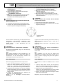
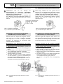
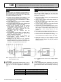
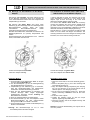
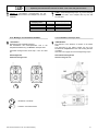
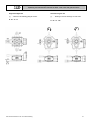

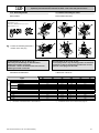
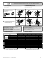
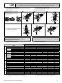
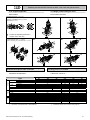
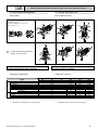
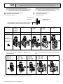
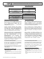
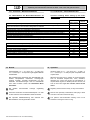
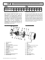
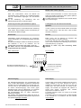
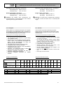
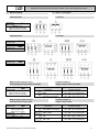
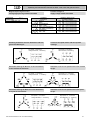


![Antriebssystem Bosch [PDF-Datei 2,48 MB]](http://vs1.manualzilla.com/store/data/006750150_1-0bf2a84ef3e0246c387c76005f2f1431-150x150.png)