1
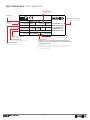
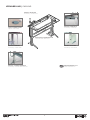
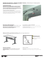
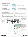
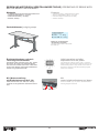
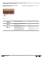
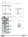
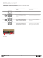
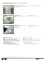
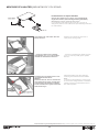
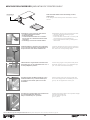
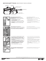
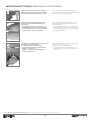
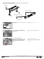
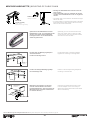
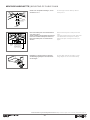
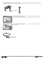
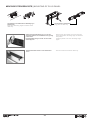
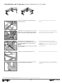
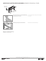
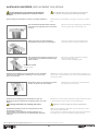
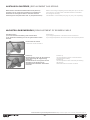
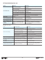
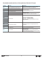
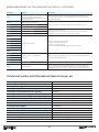
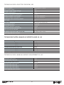
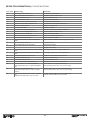
BEDIENUNGSANLEITUNG
MONTAGEANLEITUNG
USER MANUAL
ASSEMBLY INSTRUCTION
Die Bedienungs- und Montageanleitung ist vorne links unter der Tischplatte angebracht
Please find user manual and assembly instruction attached on left front side below work top
INHALT | CONTENT
Das Typenschild | The type plate������������������������������������������������������������������������������������������������������������������������������������������������������������������ 3
Wichtige Benutzerinformation | Important user information������������������������������������������������������������������������������������������������������������������������ 4-6
Verkabelung | Cabling����������������������������������������������������������������������������������������������������������������������������������������������������������������������������������� 7
Bedienung manuell verstellbarer Tische | Operating of desks with manual height adjustment������������������������������������������������������������������ 8-9
Bedienung motorisch verstellbarer Tische | Operating of desks with motor height adjustment������������������������������������������������������������� 10-11
Verstellung | Adjustment�������������������������������������������������������������������������������������������������������������������������������������������������������������������������12-13
Montage Tischplatte | Mounting of work top ������������������������������������������������������������������������������������������������������������������������������������������������ 14
Montage CPU-Halter | Mounting of CPU stand ������������������������������������������������������������������������������������������������������������������������������������������ 15
Montage Druckerbord | Mounting of printer shelf����������������������������������������������������������������������������������������������������������������������������������������� 16
Montage Anketttische | Mounting of add-on desks��������������������������������������������������������������������������������������������������������������������������������� 17-18
Montage Kabelwanne | Mounting of cable tray�������������������������������������������������������������������������������������������������������������������������������������������� 19
Montage Kabelkette | Mounting of cable chain��������������������������������������������������������������������������������������������������������������������������������������� 20-21
Montage Vertikaler Kabelkanal | Mounting of vertical cable channel���������������������������������������������������������������������������������������������������������� 22
Montage Steckerleiste | Mounting of plug panel������������������������������������������������������������������������������������������������������������������������������������������ 23
Tischgestell mit 3 Säulen | Desk frame with 3 columns������������������������������������������������������������������������������������������������������������������������������ 24
Abdeckung Quertraverse abnehmen | Remove cross rail cover����������������������������������������������������������������������������������������������������������������� 25
Austausch Gasfeder | Replacement gas spring������������������������������������������������������������������������������������������������������������������������������������� 26-27
Nachstellen Bowdenzug | Readjustment of bowden cable�������������������������������������������������������������������������������������������������������������������������� 27
Störungsbehebung M1, M2 | Remedy M1, M2�������������������������������������������������������������������������������������������������������������������������������������������� 28
Fehlermeldungen im Display des Handschalters bei Option M2����������������������������������������������������������������������������������������������������������������� 29
Error messages on the handswitch display - option M2������������������������������������������������������������������������������������������������������������������������������ 30
Technische Daten: Elektrischer Antrieb Option M1, M2������������������������������������������������������������������������������������������������������������������������������ 30
Technical Data: Electric drive M1, M2��������������������������������������������������������������������������������������������������������������������������������������������������������� 31
Technische Daten: Manuelle Verstellung H1, H2 | Technical Data: Manual height adjustment H1, H2������������������������������������������������������ 31
Befestigungsmaterial | Fixing Material��������������������������������������������������������������������������������������������������������������������������������������������������������� 32
EG-Konformitätserklärung��������������������������������������������������������������������������������������������������������������������������������������������������������������������������� 33
EG declaration of conformity����������������������������������������������������������������������������������������������������������������������������������������������������������������������� 34
2
DAS TYPENSCHILD | THE TYPE PLATE
Herstelldatum
Manufacturing date
Tischtyp
Desk type
Adresse des Herstellers
Manufacturing company
type: GMTR1-16-xx-SM
Monteur
Assembler
assembler: 4444
week/year: xx/2014
ackn.no.: 281055/1
gas springs [N]:
210
550
input: 230V AC / 50Hz / 5A
duty cycle: 30sec/270sec
Elektrische Angaben
Electrical details
Gasfederbestückung
Strength of installed gas springs
Auftragsbestätigung
Order confirmation number
Hauptstraße 2-4
96484 Wiesenfeld
Tel. 09566/88-0
[email protected]
www.leuwico.com
max. 75 kg
Maximalbelastung Tischplatte
Max. weight loading for worktop
Einschaltdauer
Beispiel: eine 30-sekündige Aktivität (motorische Auf-/
Ab-Bewegung der Tischplatte) erfordert anschließend eine
270-sekündige Pause.
Duty cycle
Example: a 30 second long activity (motorized up/down
movement of the desk top) requires a break of 270
seconds afterwards
3
WICHTIGE BENUTZERINFORMATION
IMPORTANT USER INFORMATION
Hinweise zur sicheren Benutzung am
Handschalter beachten!
Die sichere Nutzung des Sitz-Steh-Tisches
ist nur möglich, wenn die Anweisungen aus
der Bedienungsanleitung vollständig beachtet
werden.
Diese befindet sich vorne links unter der
Tischplatte.
Please note directions at the hand-set
for a safe use!
A safe use of the sit/stand desk is only possible when instructions in the user manual are
observed thoroughly. Please find user manual
attached on left front side below work top.
Intended use / field of application
The desking system GO2move has been
developped for any kind of office work, especially for monitor work. For this reason the
desks can also be equipped with monitors, fax
machines, printers etc.
For the equipment placed on the work surface
please note that the maximum load bearing
capacity as well as the duty cycle indicated in
the technical details should not be exceeded.
The possibility to vary the working positions
from sitting to standing is an important advantage of the height adjustable desks.
This device must not be used by persons
(including children) with physical, sensory or
mental disabilities or those who lack experience and/or knowledge in using such a
device.
Exceptions can be made under the supervision of a guardian or after being instructed how
to use this device.
Please keep children under supervision to
avoid playing with the device.
Bestimmungsgemäße Verwendung /
Anwendungsbereich
Das Schreibtischsystem GO2move wurde für
alle Arten von Bürotätigkeiten insbesondere
für Bildschirmanwendungen konzipiert. Somit
sind die Tische auch für die Bestückung mit
handelsüblicher Ausrüstung für Bürokommunikation wie Monitore, Faxgeräte, Drucker usw.
ausgelegt. Beim Bestücken der Arbeitsflächen mit Zusatzlasten sollte darauf geachtet
werden, dass die in den technischen Angaben
genannte maximale Belastung und Einschaltdauer nicht überschritten werden. Die
Möglichkeit, an höhenverstellbaren Tischen
GO2move die Arbeitsposition zwischen Sitzen
und Stehen zu variieren, ist besonders hervorzuheben.
Dieses Gerät kann von Kindern ab 8 Jahren und darüber sowie von Personen mit
verringerten physischen, sensorischen
oder mentalen Fähigkeiten oder Mangel an
Erfahrung und Wissen benutzt werden, wenn
sie beaufsichtigt oder bezüglich des sicheren
Gebrauchs des Gerätes unterwiesen wurden
und die daraus resultierenden Gefahren
verstehen.
Kinder dürfen nicht mit dem Gerät spielen.
Reinigung und Benutzer-Wartung dürfen nicht
von Kindern ohne Beaufsichtigung durchgeführt werden.
Mechanical dangers
Collision
When using the height adjustment of the desk
please make sure that no mobile equipment
like chairs, caddies etc. is placed underneath
the height adjustable work top.
Crush
Around the height adjustable desktop a minimum distance of 25 mm is required in order
to avoid the risk of crushing the fingers and to
avoid any injuries. Arms and legs should be
kept out of this area while using the height adjustment mechanism. This should be considered for the height adjustment and generally for
all desk components like cross rail, desktop
or telescopes which are moving towards each
other or passing each other. No persons or
limbs should be within this area when using
the height adjustment.
If no original accessories are used the user
must ensure a collision free height adjustment
Attention! Risk of injury by improper use!
Necessary work at the adjustment mechanism must only be carried out by authorized
personnel!
Mechanische Gefährdungen
Auffahren
Beim Betätigen der Tischhöhenverstellung ist
stets darauf zu achten, dass keine mobilen
Gegenstände wie Stühle, Caddies oder
andere sich unterhalb der höhenverstellbaren
Tischplatte befindet.
Quetsch- und Scherstellen
Rund um die höhenverstellbare Tischplatte
muss ein Mindestabstand von 25 mm eingehalten werden, um so Quetschstellen für
Finger zu vermeiden. Größere Gliedmaßen
wie Arme oder Beine dürfen sich während
der Verstellung nicht im quetschgefährdeten
Bereich befinden. Dies gilt für den Bereich der
Tischhöhenverstellung selbst, generell überall
dort, wo sich Tischkomponenten wie z.B.
Quertraverse –Tischplatte oder Teleskope aufeinander zu oder aneinander vorbei bewegen.
Caution! Risk of injury by gas spring
under pressure!
4
WICHTIGE BENUTZERINFORMATION
IMPORTANT USER INFORMATION
Dort dürfen sich während des Verstellens
keine Personen bzw. Gliedmaßen befinden.
Wird kein Originalzubehör verwendet, muss
die kollisionsfreie Betätigung der Verstelleinrichtung vom Anwender überprüft werden.
Achtung Verletzungsgefahr bei nicht sachgerechter Anwendung!
Notwendige Arbeiten an der Verstellmechanik
des Tischantriebs dürfen nur von autorisiertem Fachpersonal durchgeführt werden.
Weight compensation / pre-set energy
storage
Don’t operate without applied load
(weight load depends on cylinders in desk)
Don’t adjust desk without counter
pressure!
The handle-operated weight compensation
(Z3, Z4) for desks with manual height adjustment must be adapted to the actual load-bearing of the desk. If the tension of the weight
compensation is too strong the desktop will
shoot up when using the manual release
(Attention, risk of injury)!
If the tension of the weight compensation is
too low the desktop will fall downwards when
using the manual release (Attention, risk of
injury)!
Whenever changing the weight on the desk
it must be balanced out by using the crank
handle for the weight compensation.
The standard load-bearing capacity for desks
with motor or manual height adjustment is
indicated on the type plate.
Verletzungsgefahr durch vorgespannte
Gasfedern
Gewichtsausgleich / Vorgespannter
Energiespeicher
Nicht ohne Belastung betätigen (Belastung in Abhängigkeit der verbauten
Gasfederstärke)
Tischöhenverstellung nicht ohne Gegendruck betätigen!
Bei höhenverstellbaren Arbeitstischen mit
Handauslösung mit zusätzlichem Gewichtsausgleich (Z3, Z4) ist darauf zu achten, dass
der kurbelverstellte Gewichtsausgleich immer
der aktuellen Tischbelastung angepasst wird.
Bei zu stark vorgespanntem Gewichtsausgleich fährt der Tisch durch Betätigen der
Handauslösung katapultartig nach oben
(Achtung Verletzungsgefahr)!
Bei zu wenig vorgespanntem Gewichtsausgleich fällt der Tisch durch Betätigen der
Handauslösung nach unten (Achtung Verletzungsgefahr)!
Bei jeglicher Veränderung einer Lastsituation
auf dem Tisch ist das Gleichgewicht mit der
Kurbel des Gewichtsausgleichs herzustellen!
Der zulässige Belastungsbereich des elektromotorisch- oder handverstellten Tisches ist
dem Typenschild zu entnehmen.
Electrical danger
Necessary work at electrical components of
table must only be carried out by authorized
personnel.
The electrification of office furniture must be
carried out according to the corresponding
regulation of the German ‚Institut für Normung
e.V.‘ (DIN), order no. 96834.
When installing electrical conductors (wiring
for desks with motor height adjustment or
other office equipment) please make sure that
the cables cannot be crushed or damaged
when operating the adjustable components
like desk top or monitor level.
In exceptional cases the earthing of desk
frames is possible, but not absolutely necessary.
In order to avoid any danger the damaged
mains cord has to be subsituted by the manufacturer
or his service station or a similar qualified
personnel.
Elektrische Gefährdungen
Notwendige Arbeiten an elektrischen Komponenten des Tischantriebs dürfen nur von autorisiertem Fachpersonal durchgeführt werden.
Die elektrische Installation in Büromöbeln ist
in Anlehnung an die entsprechende Leitlinie
des deutschen Instituts für Normung e.V.
(DIN) Best.Nr. 96834 durchzuführen. Beim
Verlegen elektrischer Leiter (Zuleitungen für
elektrisch verstellte Tische oder von installierter Bürotechnik) ist darauf zu achten,
dass diese beim Betätigen der verstellbaren
Einrichtungen wie z.B. höhenverstellbare
Tischplatten oder Bildschirmabsenkungen
nicht gequetscht oder anderweitig beschädigt
werden können.
Cleaning instructions
Please clean top, frame, control box and control panel with a grease dissolving household
cleaner and a soft cloth. Do not use solvents,
scouring agents, or aggressive or corrosive
cleaners.
5
WICHTIGE BENUTZERINFORMATION
Further information
•User manual and assembly instruction to be
found on
http://www.leuwico.com/instructions/
•constructional alterations subject to change
Eine Erdung des Tischgestelles ist in Ausnahmefällen möglich, aber nicht zwingend
erforderlich.
Wenn die Netzanschlussleitung des Gerätes
beschädigt wird, muss sie durch den Hersteller oder seinen Kundendienst oder eine
ähnlich qualifizierte Person ersetzt werden,
um Gefährdungen zu vermeiden.
Mehrfachsteckdosen nicht verketten!
Pflegeanleitung
Tischplatte, Gestell, Antriebssteuerung und
Bedienteil nur feucht mit fettlösendem Haushaltsreiniger und weichem Tuch abwischen.
Keine Lösungsmittel, scharfe, scheuernde
bzw. ätzende Reinigungsmittel verwenden!
Weitere Informationen
•Bedienungs- und Montageanleitung auf
http://www.leuwico.com/instructions/
•Konstruktionsänderungen vorbehalten
6
VERKABELUNG | CABLING
Zubehör: Monitorarm
accessory: monitor arm
Zubehör: Kabelwanne
accessory: cable tray
Option: Kabeldurchlass
option: cable outlet
Quertraverse mit Kabelschacht
cross rail with cable duct
Zubehör: Kabelkette
accessory: cable chain
Zubehör: CPU-Halter
accessory: CPU stand
Zubehör: vertikaler Kabelkanal
accessory: vertical cable channel
Kabeldurchlass Ø 8 cm
cable outlet Ø 8 cm
7
BEDIENUNG MANUELL VERSTELLBARER TISCHE | OPERATING OF DESKS WITH
MANUAL HEIGHT ADJUSTMENT
Transportsicherung
Bei Arbeitstischen mit Handverstellung (H1, H2) ist die Höhenverstellmechanik gegen unbeabsichtiges Herausfahren gesichert.
Drehen Sie vor Inbetriebnahme die mit roten Ring gekennzeichnete Kreuzschlitzschraube komplett heraus und bewahren Sie sie
für einen eventuellen späteren Umzug auf. Die Schraube befindet
sich auf der rechten Unterseite der Quertraverse.
Transport safety mechanism
In order to avoid an uncontrolled movement the manual height
adjustment (H1, H2) is blocked. Before start-up please loosen the
recessed head screw which is marked by a red ring completely
and keep it for a possible later transport. The screw is positioned
on the right hand underside of the cross rail.
Bei Umzug, Weitertransport
For removal / further transport
muss der Tisch in die Transportstellung gebracht werden, um die
Tischmechanik nicht zu beschädigen!
Dazu Tisch in die unterste Position gegen den mechanischen
Endpunkt fahren und Handauslösung loslassen.
Transportsicherungsschraube eindrehen.
The desk has to be in the transport position in order to avoid a
damage of the mechanism!
For that purpose: Move the desk downwards to its lowest position
and let the hand lever loose.
Afterwards turn the transport safety screw in.
Höhenverstellung per Handverstellung | Manual height adjustment
Betätigung der Tischplatte immer beidhändig!
H1, H2
Adjust work top always
with two hands!
Schnellverstellung
Quick release
Handauslösehebel betätigen und Tischplatte nach oben bzw.
nach unten bewegen:
Stufenlose Arretierung, im arretierten Zustand belastbar bis
115 kg
Press the manual release and move the desktop upwards/
downwards:
Continuously lockable, weight loading up to 115 kg (when locked)
8
BEDIENUNG MANUELL VERSTELLBARER TISCHE | OPERATING OF DESKS WITH
MANUAL HEIGHT ADJUSTMENT
Gewichtsklassen | weight groups
H1: Handverstellung,
kein Gewichtsausgleich
3 Gewichtsklassen
3 weight groups:
H1:
0 - 15 kg
H1-Z1:
15 - 30 kg
H1-Z2:
30 - 45 kg
H1: manual height adjustment,
without weight compensation
H2: Handverstellung mit
Gewichtsausgleich (optional)
3 Gewichtsklassen
3 weight groups:
H2:
0 - 40 kg
H2-Z3:
20 - 60 kg
H2-Z4:
40 - 80 kg
H2: manual height adjustment with
weight compensation (optional)
(nur voreingestellter Lastausgleich)
ca. 175 Kurbelumdrehungen von Einstellung
minimaler zu maximaler Vorspannung
(preset load compensation only)
Approx. 175 turns of the crank handle from
minimum to maximum preload
• Um bei jeder Tischbelastung im Bereich von 0 bis 40 kg eine
komfortable Höhenverstellung zu ermöglichen, kann ein
Verstellmechanismus mit Hilfe einer Kurbelverstellung auf die
jeweilige Lastsituation angepaßt werden.
• Es ist darauf zu achten, dass der manuell einzustellende Gewichtsausgleich immer der aktuellen Tischbelastung angepasst
wird.
• Die Gewichtsklasse ist dem Typenschild zu entnehmen.
• In order to provide a comfortable height adjustment for
a weight-loading range from 0 to 40 kg the adjustment
mechanism can be adapted to each load by a crank handle
adjustment.
• The handle-operated weight compensation for desks with
manual height adjustment must be adapted to the actual loadbearing of the desk.
• You will find the weight class on the type plate.
Bei zu stark vorgespanntem Gewichtsausgleich fährt die
Tischplatte bei Betätigung der Handauslösung katapultartig
nach oben!
Bei zu gering vorgespanntem Gewichtsausgleich fällt die
Tischplatte bei Betätigung der Handauslösung nach unten!
If the tension of the weight compensation is too strong
the desktop will shoot up when using the manual release.
If the tension of the weight compensation is too low the
desktop will fall downwards when using the manual release.
Kurbel in das Innensechskant
an der Quertraverse stecken.
Put the handle into the hexagon socket at the cross rail.
Kurbel wird links
unter der Tischplatte
aufbewahrt
The handle is fixed
on the left hand
side underneath the
work top
stop
min.
stop
max.
Sichtschlitz
viewing slot
Clockwise rotation =
more weight
Counter clockwise rotation =
less weight
The end stop for both directions is clearly noticeable.
Please do not turn beyond
this point!
spannen
tense
entspannen
release
9
Drehen im Uhrzeigersinn =
mehr Gewicht,
Drehen gegen den Uhrzeigersinn = weniger Gewicht.
Der Endanschlag ist jeweils
deutlich spürbar, dann nicht in
diese Richtung weiterdrehen!
BEDIENUNG MOTORISCH VERSTELLBARER TISCHE | OPERATING OF DESKS WITH
MOTOR HEIGHT ADJUSTMENT
Merkmale
•
•
•
•
Features
im Gestell integrierter leise laufender Elektromotor
Verstellgeschwindigkeit ca. 70 mm/s
Geräuschentwicklung < 55 db(A)
Softstart, Softstop
•
•
•
•
quiet electro motor, integrated in the frame
speed of adjustability: approx. 70 mm/s
noise development: less than 55 db(A)
softstart, softstop
Gewichtsklassen | weight groups
2 Gewichtsklassen
2 weight groups:
M1, M2:
0 - 75 kg
M1, M2 -ZM:40 - 115 kg
M1, M2
Bedienung mit Tastschalter
unterhalb der Tischplatte
operation with button underneath
the desk top
Erstinbetriebnahme und nach
Trennung vom Stromnetz
Das Display (falls vorhanden) zeigt „000“. Fahren
Sie mit der „Ab“-Taste zum unteren Endpunkt
des Tisches und bleiben Sie weitere 3 Sekunden
auf der Taste. Bereits gespeicherte Arbeitshöhen
müssen neu gespeichert werden.
Initial operation and after
separation from the power
3s
M1: Motorverstellung
mit Einfachsteuerung Auf - Ab
The display (if existing) shows „000“. Press the
button „down“ and move the desk top down to the
lowest desk position. Stay another 3 seconds on
the button. Already memorized working heights
have to be restored.
M1:
motor height adjustment up / down
Halten Sie die Taste „Auf“ bzw. „Ab“ solange
gedrückt, bis die gewünschte Tischhöhe erreicht
wird.
Press the button „up“ or „down“ until the desired
working height is reached.
auf
Aufupup ab
Abdown
down
10
BEDIENUNG MOTORISCH VERSTELLBARER TISCHE | OPERATING OF DESKS WITH
MOTOR HEIGHT ADJUSTMENT
M2: Motorverstellung mit Komfortsteuerung (4 Speicherplätze)
M2: motor height adjustment with comfort
control (4 memory positions)
Positionstasten Display Auf
Auf Ab
position keys display up
up down
Speichertaste
memory button
Beispiel | example
1 mit den Tasten „Auf“ und „Ab“ die
gewünschte Höhe einstellen
1 adjust the desired working height by
pressing the „up“ or „down“ buttons
2 Speichertaste „S“ drücken (wird die Speichertaste ein zweites Mal gedrückt, wird
nichts gespeichert)
2 press the memory button „S“ (if this
button is pressed twice nothing will be
memorized)
3 eine der vier Positionstasten drücken
(bitte innerhalb von 5 Sekunden, sonst
wird nichts gespeichert).
Um eine gespeicherte Arbeitshöhe
anzufahren, entsprechende Positionstaste solange gedrückt halten, bis die
gespeicherte Höhe erreicht wird.
3 press one of the four position buttons
(within 5 seconds, otherwise nothing
will be memorized!)
In order to reach a memorized working
height please press the corresponding
position button until the memorized
working height is reached.
11
VERSTELLUNG | ADJUSTMENT
Höhenverstellung | height adjustment
Ausgangshöhe | initial height
52
10
max.
130
68-78
78
68
Fußausleger mit zwei bis drei Umdrehungen lockern. Dabei muss der Widerstand
überwunden werden
Loosen the extension feet with 2-3 turns.
The resistance has to be overcome.
Stufenlose Verstellung
die Scala an der Säule ermöglicht eine
korrekte Einstellung.
Continuous adjustment:
the scale on the column enables a correct
adjustment
Fußausleger wieder festziehen.
Tighten the extension feet again.
68 cm
verstellbarer Fußteller zum Höhenausgleich
adjustable foot plates for the adaption to uneven floors
72 cm
78 cm
12
VERSTELLUNG | ADJUSTMENT
Änderung der digitalen Ausgangshöhe | Change of the initial height
5s
1 Arbeitstisch in unterste Position
bringen
1 move the desk downwards to the
lowest position
2 Taste „S“ drücken
2 press the button „S“
3 für ca. 5 Sekunden die „Ab“-Taste
drücken, bis das Display zu blinken
beginnt
3 press the button „down“ for approx. 5
seconds until the display starts blinking
4 jetzt mit der „Auf“- bzw. „Ab“-Taste die
neu eingestellte Ausgangshöhe einstellen. (der Tisch fährt dabei nicht!)
4 now adjust the new initial height with
the „up“ or „down“ button (the desk is
not moving)
5 ist die Position richtig eingestellt, mit
Taste „S“ die neue Höhe speichern.
(Das Display blinkt nun nicht mehr)
5 after the correct position is adjusted
please save the new height with the
button „S“ (the display is not blinking
any longer)
Positionstasten Display Auf Ab
position keys display up
up down
Speichertaste
memory button
13
MONTAGE TISCHPLATTE | MOUNTING OF WORK TOP
Tischplatte auf die Plattenauflagen legen
und mit je vier Schrauben (Pos. 24*) an den
Säulen befestigen.
Put the desktop on the top supports and fix it
with four screws (pos. 24*) at each column.
Handverstellung
Bedienteil mit zwei Schrauben (Pos.22)
fixieren
Manual adjustment
fix the operating device with two screws
(pos. 22)
Motorverstellung
• Bedienteil mit drei Schrauben (Pos. 23)
fixieren
• Kabel einklipsen
Motor adjustment
• fix the operating device with three screws
(pos. 23)
• put the cables into the clips
Klips
Clips
Demontage der Tischplatte
Removal of the work top
Tisch ganz nach oben fahren, sonst besteht Verletzungsgefahr durch vorgespannte Gasfedern!
Raise work top completely otherwise danger of injury
due to prestressed gas spring!
Die Tischplatte wird mit dem Unterrahmen (Dreikantrohr und
Plattenauflagen) sowie der Kabelwanne (falls vorhanden)
entfernt, daher bitte:
• Tischplatte komplett leer räumen
• Kabel aus den Kabeldurchlässen ziehen
• Kabel in der Kabelwanne vom Untergestell trennen
• falls vorhanden Kabelkette von der Tischplatte trennen
The desk top will be removed together with the metal frame
(triangular tube and desk top supports) and the cable tray (if
existing), therefore, please:
• clear the desk top completey
• remove the cables from the cable outlets
• untie the cables in the cable tray from the desk frame
• if existing remove the cable chain from the desk top
*Genaue Bezeichnung des Montagematerials siehe S. 32 | *Exact description of the assembly material see page 32
14
MONTAGE CPU-HALTER | MOUNTING OF CPU STAND
Für Arbeitstische mit Option Kabelkette
Wird der CPU-Halter innen montiert, muss die Kabelkette
eingerutscht werden (siehe Montageanleitung Kabelkette)
CPU-Halter
CPU stand
Workstations with an optional cable chain
If you install the CPU stand at the inner part, you have to
change the position of the cable chain (see assembly instruction
for cable chains)
14-24 cm
CPU-Halter innen oder außen über das
Beinprofil führen...
Slide the CPU stand over the inner or
outer part of the leg profile...
...und durch Anziehen der KunststoffGewindestifte (Pos. 10*) in die Profilnut
oberhalb der Fußelemente klemmen.
...and fix it by fastening the plastic core-pin
(pos. 10*) into the profile groove upside
the feet.
Einstellung der CPU-Breite durch Lösen
der Rändelschraube M6x15
Hinweis
Damit der Rechner auch bei verbreiterter
CPU-Halter-Fläche sicher und fest steht,
sind die beiden mitgelieferten selbstklebenden Pufferlinsen an gekennzeichneter
Stelle anzubringen.
Adjust the widths of the CPU stand by
loosening the knurled head srew M6x15
Note
To ensure a safe positioning of the computer even if the storage surface is extended
please fix the two included rubber feet at
the marked position.
Position Pufferlinsen
position rubber feet
*Genaue Bezeichnung des Montagematerials siehe S. 32 | *Exact description of the assembly material see page 32
15
MONTAGE DRUCKERBORD | MOUNTING OF PRINTER SHELF
Druckerbord
Printer shelf
Falls Gewindeschlitten bereits werksseitig montiert,
weiter mit 03.
If the sledges have already been assembled, continue
with 03.
45
50
Fußausleger vorne und hinten demontieren:
• montierte Arbeitshöhe merken!
• Seitenteil anheben
• Innensechskantschrauben mit 2-3 Umdrehungen (bis der 2. Widerstand überwunden
ist) lockern
• Fußausleger nach unten herausschieben
Disassemble the front and rear extension feet:
• note the assembled working height!
• lift the side part up
• loosen the Allen screws with 2-3 turns (until
overcoming the second resistance)
• remove the extension feet by shifting them
downwards
02
Gewindeschlitten in die Nuten der Längsseiten
vorne und hinten einführen und Fußausleger in
entsprechender Höhe wieder festklemmen.
Insert the sledges into the grooves of the long
sides at the front and back and refix the extension feet in the corresponding height.
03
Haltewinkel auf vorgebohrtem Druckerbord mit
Schrauben (Pos. 8* für Spanplatten bzw. Pos. 9
für Kompaktplatten) fixieren.
Fix the fixing angle on the premounted printer
shelf with screws (pos. 8* for chipboard tops,
pos. 9 for solid core laminated tops).
Druckerbord über das Beinprofil führen und in
Gewindeschlitten mit je 2 Gewindestifte (Pos.
2) befestigen, Schrauben jedoch noch nicht
festziehen!
Put the printer shelf over the leg profile and
fix it in the sledges with 2 threaded pins each
(pos.2). Do not tighten the screws yet!
Druckerbord in gewünschter Höhe positionieren
und Gewindestifte jetzt festziehen.
Mit je 2 Hutmuttern (Pos. 3) kontern.
Position the printer shelf in the requested height
and fix the threaded pin.
Secure it with 2 cap nuts
(pos. 3) each.
01
04
05
*Genaue Bezeichnung des Montagematerials siehe S. 32 | *Exact description of the assembly material see page 32
16
MONTAGE ANKETTTISCHE | MOUNTING OF ADD-ON DESKS
Arbeitstisch
work desk
Anketttisch
add-on desk
Stabilisierungsrohre
stabilizing tubes
72 cm
(Standardeinstellung)
(standard)
Seitenteil
side part
Fußausleger
extension foot
01
02
03
04
Verkettungswinkel
connecting angle
Plattenauflage
support for work top
Falls werksseitig nicht geschehen:
Tischplatte des Arbeitstisches in oberste
Position bringen.
Fußausleger vorne und hinten demontieren:
• montierte Arbeitshöhe merken!
• Seitenteil anheben
• Innensechskantschrauben mit 2-3 Umdrehungen (bis der 2. Widerstand überwunden
ist) lockern
• Fußausleger nach unten herausschieben
If not prepared in production:
move the desk top of the work desk to the
uppermost position.
Disassemble the front and rear extension feet:
• note the assembled working height!
• lift the side part up
• loosen the Allen screws with 2-3 turns (until
overcoming the second resistance)
• remove the extension feet by shifting them
downwards
Falls werksseitig nicht geschehen:
Gewindeschlitten in die Nuten der Längsseiten
vorne und hinten einführen und Fußausleger in
entsprechender Höhe wieder festklemmen.
If not prepared in production:
Insert the sledges into the grooves of the long
sides at the front and back and refix the extension feet in the corresponding height.
• asymmetrischen Verkettungswinkel mit dem
längeren Schenkel nach vorne über das
Beinprofil führen und mit dem Gewindeschlitten und je 2 Gewindestiften (Pos. 2*) leicht
anschrauben.
• Oberkante Verkettungswinkel in 69 cm Höhe
vom Fußboden positionieren und Gewindestifte festziehen. Diese Einstellung gilt für
eine Arbeitshöhe von 72 cm. Bei anderer
Arbeitshöhe des Anketttisches Position
entsprechend anpassen.
• mit je 2 Hutmuttern (Pos. 3) kontern.
• put the asymmetrical connecting angle the
longer part to the front] over the leg profile
and fix it slightly with the sledge and 2 threaded pins each (pos. 2*)
• position the connecting angle at a height
of 69 cm from the floor and fix the threaded
pins. This position is used for a working
height of 72 cm. If the add-on desk has a
different height please adapt the position accordingly.
• secure the angle with 2 cap nuts (pos. 3)
each.
Aluminium-Nivellier-Hülsenschrauben (Pos.
4) vorne und hinten in Verkettungswinkel
eindrehen.
Turn the aluminium jackscrews (pos. 4) at the
front and back into the connecting angle.
*Genaue Bezeichnung des Montagematerials siehe S. 32 | *Exact description of the assembly material see page 32
17
MONTAGE ANKETTTISCHE | MOUNTING OF ADD-ON DESKS
05
06
07
Falls werksseitig nicht geschehen, müssen
Plattenauflage und Stabilisierungsrohre des
Anketttisches aneinander geklemmt werden.
If not prepared in production the desk top
supports and the stabilizing tubes of the add-on
desk have to be clamped together.
Plattenauflage und Stabilisierungsrohre an
die Platte des Anketttisches befestigen (in
Rückenlage):
• Plattenauflage mit 2x Schrauben (Pos. 7*)
• Stabilisierungsrohre mit 4x Schrauben (Pos.
8 für Spanplatten bzw. Pos. 9 für Compactplatten) fixieren (jeweils vorgebohrt)
Top supports and stabilizing tubes have to
be fixed on the desk top of the add-on desk
(supine position):
• fix the top support with 2 x screws (pos. 7*)
• fix the stabilizing tubes with 4 x screws (pos.
8 for chipboard tops and pos. 9 for scl tops)
(each one predrilled)
Anketttisch auf Verkettungswinkel legen und mit
Schrauben (Pos. 5) befestigen.
Er muss mit der Tischplatte fluchten:
• mit Aluminium-Nivellier-Hülsenschrauben
(Bild No. 4) ausrichten.
• Spalt 25 - 30 mm parallel einstellen und
Schrauben festziehen.
Lay the add-on desk on the connecting angle
and fix it with screws (pos. 5).
It must be aligned with the desk top:
• fix it with aluminium jackscrews (pic. no. 4).
• Adjust the space 25-30 mm parallel and fix
the screws.
*Genaue Bezeichnung des Montagematerials siehe S. 32 | *Exact description of the assembly material see page 32
18
MONTAGE KABELWANNE | MOUNTING OF CABLE TRAY
Kabelwanne
cable tray
Position T-Ausschnitte
Position T-cut-outs
01
02
03
Kabelwanne von vorne über das hintere Dreikantrohr schieben
Put the cable tray from the front over the
triangular tube
Von der Rückseite des Arbeitstisches aus 2
Montagewinkel in die T-Ausschnitte der Kabelwanne einführen ...
Put 2 mounting angles from the back of the
workstation into the T-cut-outs of the cable
tray...
...und an die Kabelwanne anlegen.
Jeweils 1 Flachrundschraube (Pos. 11*) und 1
Rändelmutter (Pos. 12) wie gezeigt montieren.
Die Kabelwanne wird durch Festziehen der
beiden Rändelmuttern an das Dreikantrohr
geklemmt.
...and fix them at the cable tray.
Install each with 1 cup neck bolt (Pos. 11*) and
1 knurl nut (Pos. 12) as shown. The cable tray
gets fixed to the triangular tube by tightening
both knurl nuts.
Rändelmutter innen!
Knurled nut inside!
*Genaue Bezeichnung des Montagematerials siehe S. 32 | *Exact description of the assembly material see page 32
19
MONTAGE KABELKETTE | MOUNTING OF CABLE CHAIN
• Montage der Kabelkette links und/oder rechts am
Tisch möglich.
• Ist ein CPU-Halter innen am Seitenteil des Tisches
montiert, muss die Kabelkette um 28 cm eingerückt
werden.
Krallen außen!
clamps outside!
• The cable chain can be fixed on the left and/or right
side of the desk.
• If a CPU holder is mounted at the inside of the desk
frame side part the cable chain must be moved by
28 cm to the centre of the desk.
Kabelkette
(rechts montiert)
cable chain
(fixed at the right side)
Optional kann die Kabelkette für dickere
Kabelstränge vorder- und rückseitig genutzt
werden, wenn jedes zweite Krallenpaar
herausgenommen und zur Rückseite hin
wieder eingesetzt wird.
Optionally you can use the front and rear
side of the cable chain for stronger cable
cords. Remove every second pair of claws
and insert it to the rear side.
Die drei Teile des Befestigungsadapters
zusammenstecken.
Position bei Montage rechts
Put the three parts of the fixing adapter
together for mounting on the right side.
Position des 3teiligen Befestigungsadapters bei Montage links
Position of the threepart fixing adapter for
mounting on the left side.
Befestigung des Adapters an die Quertraverse durch Eindrücken der beiden
Kunststoff-Blindnieten. (Für Demontage die
Blindnietenköpfe mit einem Schraubenzieher einfach anheben.)
Insert the two plastic blind rivets in order
to fix the adapter on the cross rail. (For
demounting simply lift the blind rivet heads
with a screw-driver).
Winkel 1
angle 1
Quertraverse
cross rail
Kunststoff-Blindnieten
plastic blind rivets
*Genaue Bezeichnung des Montagematerials siehe S. 32 | *Exact description of the assembly material see page 32
20
MONTAGE KABELKETTE | MOUNTING OF CABLE CHAIN
Winkel 2 an Tischplatte befestigen, mit 2x
Schraube Pos. 9*
Fix the angle 2 at the desk top with 2x
screw pos. 9*
Das erste Krallenpaar durch Herausziehen
vom Strang lösen.
Winkel 2 entlang der Rückseite des Strangs
hinter dem zweiten Krallenpaar einführen.
Das erste Krallenpaar nun wieder hineindrücken.
Remove the first pair of clamps from the
cord.
Insert the angle 2 along the rear side of the
cord behind the second pair of clamps.
Put the first pair of clamps into the cord
again.
Kabelkette in gleicher Weise an Winkel 1
des Befestigungsadapters der Quertraverse befestigen.
Fix the cable chain at the angle 1 of the
fixing adapter of the cross rail similarly.
Winkel 2
angle 2
Pos. 9
Strang
cord
Krallenpaar 2
pair of clamps 2
Krallenpaar 1
pair of clamps 1
*Genaue Bezeichnung des Montagematerials siehe S. 32 | *Exact description of the assembly material see page 32
21
MONTAGE VERTIKALER KABELKANAL | MOUNTING OF VERTICAL CABLE CHANNEL
vertikaler Kabelkanal
vertical cable channel
Eine Seite des vertikalen Kabelkanals innen am
Beinprofil des Arbeitstisches komplett einfügen,
die zweite Seite zunächst nur oben einhängen.
Durch leichtes Klopfen mit dem Handballen
rastet das transluszente Verkabelungsprofil in
das Beinprofil ein.
vertikaler Kabelkanal
vertical cable channel
22
Insert one side of the vertical cable channel
completely inside the leg profile of the workstation, and hang the other side only loosely in the
upper part.
The translucent cabling profile snaps into the
leg profile with a slide beating by the hand.
MONTAGE STECKERLEISTE | MOUNTING OF PLUG PANEL
Steckerleiste mit Haltewinkel für Befestigung in
Kabelwanne
Plug panel with fixing angle for fixation at the
cable tray
Steckerleiste in Kabelwanne
plug panel in cable tray
Äußere Kunststoffabdeckungen von der Steckerleiste abziehen und Haltewinkel wie gezeigt
positionieren.
Kunststoffabdeckungen wieder auf den Haltewinkel klippsen.
Remove the outer plastic cover from the plug
panel and position the fixing angle as shown in
the picture.
Push the plastic cover onto the fixing angle
again.
Die Rändelmuttern sitzen in der Kabelwanne
innen.
The knurl nuts are inside the cable tray.
23
TISCHGESTELL MIT 3 SÄULEN | DESK FRAME WITH 3 COLUMNS
Die beiden Traversenteile am Wellenadapter
zusammenstecken.
Put both rail parts together at the mandrel
adapter.
Gestellteile mit 4x Schrauben (Pos. 13*) und 4x
Muttern (Pos. 14) mit Innensechskantschlüssel
SW3 und Schraubenschlüssel SW8 verbinden.
Connect the frame parts with 4x screws (pos.
13*) and 4x nuts (pos. 14) with an allen wrench
SW3 and with a screw wrench SW8.
Gleichlaufwelle und Wellenadapter durch
Einschrauben des Gewindestiftes (Pos. 15) mit
einem Innensechskantschlüssel SW3 gegen
Verdrehen sichern.
Wichtig
Die gelben Markierungen auf Welle und Adapter
müssen fluchten!
Insure the synchronous mandrel and the
mandrel adapter against turning by bolting the
threaded pin (pos. 15) with a allen wrench SW3.
Important
The yellow marks at the mandrel and adapter
must be aligned.
Auflegen der Traversenabdeckungen und...
Place the cross rail cover on the cross rail and...
...mit Schrauben (Pos. 16) im Aluminium-Gussteil und in der Blechtraverse fixieren.
...fix it with screws (pos. 16) in the aluminium
casting and with screws (pos. 17) in the metal
cross rail.
*Genaue Bezeichnung des Montagematerials siehe S. 32 | *Exact description of the assembly material see page 32
24
ABDECKUNG QUERTRAVERSE ABNEHMEN | REMOVE CROSS RAIL COVER
Abdeckung
cover plate
Quertraverse
cross rail
Alle Verschraubungen der Traversenabdeckung
mit Werkzeug Torx 25 lösen.
Loose all srews of the cross rail cover with the
Torx 25 tool.
Abdeckung schräg nach oben abnehmen.
Demount the cover transversely up.
Montage in umgekehrter Reihenfolge.
Installation in reversed order.
*Genaue Bezeichnung des Montagematerials siehe S. 32 | *Exact description of the assembly material see page 32
25
AUSTAUSCH GASFEDER | REPLACEMENT GAS SPRING
Die Tischplatte muss sich aufgrund der Verletzungsgefahr durch gespannte Gasfedern in oberster Position
befinden!
The desktop has to be in the uppermost position because of the risk of injury by the tensed gas springs!
01 Demontage der Tischplatte: vgl. Seite 14 (komplett ausführen)
01 Demounting of the desktop: see page 14 (carry out completely)
02 2 Sechskant-Einstellschrauben SW8 (für
die unteren Führungsrollen) lösen und herausnehmen.
02 Loose 2 hexagon adjusting screws SW8 (for
the lower guide rolls) and take them out.
03 Nur bei Tischen mit Handverstellung:
Vierkantmutter SW13 lösen und abnehmen.
03 Only for desks with manual adjustment:
Loose the square nut SW13 and take it off.
04 4 Senkschrauben Antrieb Torx25 lösen und
herausnehmen, anschließend Stabilisierungsplatte entfernen.
04 Loose 4 counter sunk screws actuation
Torx25 and take them out.
Then remove the stabilizing plate.
Stabilisierungsplatte
stabilizing plate
05 Säulen durch Betätigung der Handauslösung oder des Bedienelementes der elektrischen Verstellung ca. 20 cm nach unten
fahren und arretieren.
05 Move the columns about 20 cm downwards by using the manual control or the operational control of the electrical adjustment
and fix the position.
06 Gasfeder gegen den Uhrzeigersinn herausdrehen und durch eine neue ersetzen.
07 Säulen durch Betätigung der Handauslösung oder des
Bedienelementes der elektrischen Verstellung wieder nach oben
fahren
06 Unscrew the gas spring counterclockwise
and replace it by a new one.
07 Move the columns again upwards by using the manual control
or the operational control of the electrical adjustment
Attention: Column might move down impulsively!
Achtung: Säule fährt evtl. stoßartig nach unten!
08 Screw the stabilizing plate again on the profile with counter
sunk screws Torx25 (see 04).
Turn the square nut hand-screwed at the gas spring and justify it
according to the cut-out in the desktop support (see 03)
08 Stabilisierungsplatte wieder mit Senkschrauben Torx25
aufschrauben (siehe 04).
Vierkantmutter auf die Gasfeder handfest aufdrehen und
entsprechend der Aussparung in der Plattenauflage ausrichten
(siehe 03)
*Genaue Bezeichnung des Montagematerials siehe S. 32 | *Exact description of the assembly material see page 32
26
AUSTAUSCH GASFEDER | REPLACEMENT GAS SPRING
09 Die beiden Sechskant-Einstellschrauben SW8 (siehe 02)
eindrehen und ca. jeweils eine Umdrehung nach merkbarem
Widerstand im Uhrzeigersinn drehen. Nicht fest anziehen!
09 Turn the hexagon adjusting screws SW8 (see 02) on and turn
each with one revolution after noticeable resistance clockwise.
Do not tighten securely!
10 Montage der Tischplatte siehe Seite 14 (komplett ausführen)
10 Installation of the desktop see page 14 (carry out completely)
NACHSTELLEN BOWDENZUG | READJUSTMENT OF BOWDEN CABLE
Erforderlich wenn,
a) sich die Tischhöhenverstellung nicht auslösen lässt
b) die Tischhöhenverstellung nicht an der gewünschten Position
einrastet
Necessary if
a) the height adjustment of the desk cannot be released
b) the height adjustment cannot be locked in the required position
Kontermutter SW 8 lösen
Loosen the counter nut SW 8
Problem a):
Einstellschraube gegen den Uhrzeigersinn
drehen (Erhöhung der Zugspannung)
Problem b):
Einstellschreibe im Uhrzeigersinn drehen
(Reduzierung der Zugspannung)
Anschließend Kontermutter SW 8 wieder
festziehen!
Problem a):
turn the adjustment screw counterclockwise
(increasing the tension)
Problem b):
turn the adjustment disc clockwise (decreasing
the tension)
Afterwards refix the counter nut SW 8
*Genaue Bezeichnung des Montagematerials siehe S. 32 | *Exact description of the assembly material see page 32
27
STÖRUNGSBEHEBUNG M1, M2
Fehler
Ursache
Behebung
Keine Stromversorgung
Prüfen, ob Steckdose Spannung führt, Netzkabel
einstecken
max. Zusatzlast gem. Techn.
Daten überschritten
Gewicht reduzieren
Mindest- Zusatzlast gem. Techn.
Daten (Option –ZM) unterschritten
Mindest- Gewichtsbelastung auf Tischplatte
aufbringen
max. Einschaltdauer überschritten
Steuerung aktiviert sich nach ca. 9 Minuten
selbsttätig wieder
Antrieb defekt
Wenden Sie sich an den Kundendienst
Bedienteil defekt
Wenden Sie sich an den Kundendienst
Tisch fährt nur langsam
nach unten
Steuerung erwartet neue Initialisierung
vgl. Seite 9, Erstinbetriebnahme/nach Trennung
von Stromnetz
Tisch fährt kurz nach
oben und bleibt stehen
max. Zusatzlast überschritten
Gewicht reduzieren
Tisch fährt kurz nach
unten und bleibt stehen
Mindest- Zusatzlast unterschritten
Mindest- Gewichtsbelastung auf Tischplatte
aufbringen
Display - Anzeige ohne
Funktion
hochfrequente Störfelder im
Bereich von industriellen Umgebungen (z.B. durch Frequenzumformer)
Tisch mit Höhenanzeige ist für Anwendung in
beschriebenen Umgebungen nicht geeignet.
Tisch an geeigneter Stelle ohne hochfrequente
Störfelder aufstellen.
Tisch fährt nicht
REMEDY M1, M2
Fault
Drives not working
Possible Cause
Remedy
Power cord is not connected
check if socket receives voltage, plug
power cord into socket
max. additional weight based on
technical data is exceeded
reduce weight
minimum additional weight falls below add minimum weight
technical data (option -ZM)
max. switch-on time is exceeded
control activates itself again after 9 min.
Drive is defective
Contact customer service
Control unit is defective
Contact customer service
Desk is moving down slowly control waits for new initialisation
see page 9, first start-up and after separation from the power
desk is moving up briefly
and stops
reduce weight
max. additional weight is exceeded
desk is moving down briefly minimum additional weight falls below add minimum weight
and stops
Display without function
High frequency interference fields in
industrial surroundings (e.g. caused
by frequency converter)
28
Table with height display cannot be used
in these surroundings. Set up table in
appropriate spot without high frequency
interference fields.
FEHLERMELDUNGEN IM DISPLAY DES HANDSCHALTERS BEI OPTION M2
Anzeige
Ursache
Behebung
hot
Die Steuerung überwacht die Einschaltdauer (zeit-gesteuert) und ihre max. Temperatur. Ein Wert wurde überschritten.
Warten Sie bis die Anzeige „hot“ erlischt, danach
arbeitet der Tisch wieder ordnungsgemäß.
E00
Interner Fehler Kanal 1
E01
Interner Fehler Kanal 2
E02
Interner Fehler Kanal 3
E12
Defekt Kanal 1
E13
Defekt Kanal 2
E14
Defekt Kanal 3
Netzstecker ziehen!
und an den Kundendienst wenden
Netzstecker ziehen!
Korrekten Anschluß der Komponenten an die Steuerung prüfen und erneut an Netz anschließen
E24
E25
Überlast Motor
Es kann eine Überlast vorliegen:
Nach oben – Tischplatte entlasten
Nach unten – Tischplatte belasten
Hindernisse entfernen, die ein Verfahren der Tischplatte verhindern
Falscher Motor an Kanal
Passendes Motorkabel an dazugehörige Buchse
anschließen
E67
Überspannung
Netzstecker ziehen!
und an den Kundendienst wenden
E81
Interner Fehler
Reset durchführen:
Netzstecker ziehen und nach einigen Sekunden
wieder einstecken.
Sollte der Fehler öfters auftreten, Netzstecker ziehen!
und an den Kundendienst wenden
E26
E48
E49
E60
E62
E36
E37
E38
E61
29
ERROR MESSAGES ON THE HANDSWITCH DISPLAY - OPTION M2
Display
Cause
Remedy
hot
The compact control unit is fitted
with overheating protection.
Overheating has caused it to stop
the control unit.
Wait until the control unit has cooled down and HOT is
no longer displayed. The COMPACT control unit is then
operational again.
E00
Internal error channel 1
E01
internal error channel 2
E02
internal error channel 3
E12
Defect Channel 1
E13
Defect Channel 2
E14
Defect Channel 3
Unplug power cord and contact the customer service.
Unplug the control unit.
Or: Plug in the correct motor to the motor socket that
shows the error. Start the control unit again.
E24
E25
E26
Overcurrent motor
There might be an overload
to raise - unload work top
to lower - load work top
remove jammed objects from the driving area
Wrong motor connected to
channel
Plug in the correct motor to the motor socket that shows
the error. Reset all motors.
E67
High voltage
Unplug power cord and contact the customer service.
E81
Internal error
Make a manual reset. Unplug power cord and plug it in
again after a few seconds. If this error occurs frequently,
unplug the power cord and contact the customer service.
E48
E49
E60
E62
E36
E37
E38
E61
TECHNISCHE DATEN: ELEKTRISCHER ANTRIEB OPTION M1, M2
Spannungsversorgung
207 V bis 254,4 V / 50 Hz
Max. Output Power
380W
Standby- Leistung, primär
0,1W
Zulässiger Temperaturbereich für Betrieb
0-30°C
Zulässiger Temperaturbereich für Lagerung
-40-85°C
Zulässige relative Luftfeuchtigkeit für Betrieb
5-85% (nicht kondensierend)
Zulässige relative Luftfeuchtigkeit für Lagerung
5-90% (nicht kondensierend)
Schutzklasse mit Erdung
I
IP - Klasse
IP20
Max. Einschaltdauer
10% (2 min. on / 18 min. off)
Verstellgeschwindigkeit
Ca. 70mm/s
Geräuschentwicklung
< 55 db (A)
Softstart / Softstop - Funkion
Vorhanden
Statische Belastung* Maximal
115 kg
Max. Belastung* -M1/-M2
0-75 kg
Max. Belastung* Option –ZM (bei -M1/-M2)
Min. 40 kg – Max. 115 kg
*Last gleichmäßig auf Tischplatte verteilt
30
TECHNICAL DATA: ELECTRIC DRIVE M1, M2
Supply voltage
207 V to 254,4 V / 50 Hz
Max. Output Power
380W
Standby power, primary (typical)
0,1W
Ambient temperature
0-30°C
Storage and transport temperature
-40-85°C
Relative humidity (for operation)
5-85% (non condensing)
Relative humidity (for storage)
5-90% (non condensing)
Protection class (with earth terminal)
I
IP - class
IP20
Duty cycle
10% (2 min. on / 18 min. off)
Adjustment velocity
Ca. 70mm/s
Noise development
< 55 db (A)
Softstart / Softstop - Function
available
Max. weight load* at fixed height
115 kg
Max. weight load* -M1/-M2
0-75 kg
Max. weight load* option –ZM (-M1/-M2)
Min. 40 kg – Max. 115 kg
*weight distributed evenly on work top
TECHNISCHE DATEN: MANUELLE VERSTELLUNG H1, H2
Statische Belastung Maximal*
115 kg
Verfahrbare Belastung* Option H1
0-15 kg
Verfahrbare Belastung* Option H1-Z1
15-30 kg
Verfahrbare Belastung* Option H1-Z2
30-45 kg
Verfahrbare Belastung* Option H2
0-40 kg
Verfahrbare Belastung* Option H2-Z3
20-60 kg
Verfahrbare Belastung* Option H2-Z4
40-80 kg
*Last gleichmäßig auf Tischplatte verteilt
TECHNICAL DATA: MANUAL HEIGHT ADJUSTMENT H1, H2
Maximum static load*
115 kg
Movable load option* H1
0-15 kg
Movable load option* H1-Z1
15-30 kg
Movable load option* H1-Z2
30-45 kg
Movable load option* H2
0-40 kg
Movable load option* H2-Z3
20-60 kg
Movable load option* H2-Z4
40-80 kg
*weight distributed evenly on work top
31
BEFESTIGUNGSMATERIAL | FIXING MATERIAL
Pos. / item
Bezeichnung
Denotation
1
Gewindeprofil ETXX-01591
Thread profile ETXX-01591
2
Gewindestift M5x10 DIN 913 DI
Threaded pin M5x10 DIN 913 DI
3
Hutmutter M5 DIN 917 VZ
Cap nut M5 DIN 917 VZ
3a
Scheibe 5,3 DIN 125 VZ
Washer 5,3 DIN 125 VZ
4
Nivellier-Hülsenschraube ETXX-0028
Levelling screw ETXX-0028
5
Zylinderschraube M6x30 DIN 6912 VZ
Cylinder head screw M6x30 DIN 6912 VZ
6
Scheibe 6,4 DIN 125 VZ
Washer 6,4 DIN 125 VZ
7
Rändelschraube M6
Knurled screw M6
8
Spax RW 5x20 VZ (für Spanplatten)
Wooden screw RW 5x20 VZ (for chipboard)
9
Schraube für Kunststoffplatten 5x12 VZ
Screw for plastic sheets 5x12 VZ
10
Kunststoff-Gewindestift M8x8
Plastic threaded pin M8x8
11
Flachrundschraube M5x16 DIN 603 VZ
Cup neck bolt M5x16 DIN 603 VZ
12
Kunststoff-Rändelmutter M5
Plastic knurled screw M5
13
Linsenschraube M5x16 mit Innensechskant
SW3
Fillister head screw M5x16 with hexagon socket SW3
14
Sperrzahnmutter M5 blank
Locknut M5 blank
15
Gewindestift M6x16 DIN 914 blank
Innensechskant SW3
16
Gewindefurchende Schrauben für Leichtmetalle
5x15
Thread grooving screws for light metals 5x15
17
Gewindefurchende Schrauben für Stahlbleche
5x10
Thread grooving screws for steel plates 5x10
18
Senkschraube M5x12 DIN 7991 VZ
Counter sunk screw M5x12 DIN 7991 VZ
19
Scheibe 5,3 DIN 9021 VZ
Washer 5,3 DIN 9021 VZ
20
Hutmutter M5 DIN 917 VZ
Cap nut M5 DIN 917 VZ
21
Zylinderschraube M5x10 DIN 7984 VZ
Cylinder head screw M5x10 DIN 7984 VZ
22
Euroschrauben 6,3 x 19 (für Spanplatten)
Schneidschrauben Ø 5 x 12 (für Kompaktplatten)
Euro screws 6,3 x 19 (for chipboard tops)
Thread cutting screws diam. 5 x 12 (for scl tops)
23
Spax Ø 3 x 20 (für Spanplatten)
Schneidschrauben Ø 3,5 x 12 (für Kompaktplatten)
Wooden screw diam. 3 x 20 (for chipboard tops)
Thread cutting screws diam. 3,5 x 12 (for scl tops)
24
Zylinderkopfschrauben M6 x 25 (für Spanplatten)
Cylinder head bolts M6 x 16 (for scl tops)
Cylinder head bolts M6 x 25 (for chipboard tops)
Cylinder head bolts M6 x 16 (for scl tops)
hexagon socket SW3
32
Hersteller
Name
Straße
Stadt
Land
Telefon
Telefax
Email
Leuwico GmbH
Hauptstr. 2-4
96484 Wiesenfeld / Meeder
Germany
+49 (0)9566 88 0
+49 (0)9566 88 114
[email protected]
EG – Konformitätserklärung
im Sinne der EG-Maschinen-Richtlinie 2006/42EG, Anhang II
Hiermit erklären wir, dass das nachstehend bezeichnete Gerät in der von uns in Verkehr gebrachten
Ausführung den Anforderungen der nachfolgend aufgeführten EG- Richtlinien entspricht. Bei einer nicht
mit uns abgestimmten Änderung oder unsachgemäßem Verwendungszweck verliert diese Erklärung ihre
Gültigkeit.
Büro – Steh - Sitzarbeitsplatz GO2move
Bezeichnung des Gerätes:
Typ:
Angewendete EG- Richtlinien:
Zum Beispiel GMTR1-12-M1/M2
Angewendete harmonisierte europäische
Normen:
DIN EN ISO 12100:2011
DIN 57700 Teil 238
VDE 0100 Teil 724/06.80 (in Anlehnung)
DIN EN 60335-1:2002 +A11:2004 +A1:2004
+A12:2006 +A2:2006 +A13:2008 +A14:2010
+A15:2012
DIN EN 349:2008
DIN EN ISO 13857:2008
EN 61 000-3-2
2006/42/EG Maschinenrichtlinie
2004/108/EG Richtlinie zur elektromagnetischen Verträglichkeit
2006/95/EG Niederspannungsrichtlinie
Sicherheit von Maschinen – Risikobeurteilung und Risikominderung
Sicherheit elektrischer Geräte für den Hausgebrauch und ähnliche Zwecke
Elektrische Anlagen in Möbeln und ähnlichen Einrichtungsgegenständen
Sicherheit elektrischer Geräte für den Hausgebrauch
Sicherheit von Maschinen – Mindestabstände zur Vermeidung des
Quetschens von Körperteilen
Sicherheit von Maschinen - Sicherheitsabstände gegen das Erreichen von
Gefährdungsbereichen mit den oberen und unteren Gliedmaßen
Elektromagnetische Verträglichkeit - Grenzwerte der
Oberschwingungsströme
Elektromagnetische Verträglichkeit - Begrenzung von
Spannungsänderungen
Elektromagnetische Verträglichkeit - Störaussendung
Elektromagnetische Verträglichkeit - Störfestigkeit
Elektrische Geräte für den Hausgebrauch und ähnliche Zwecke Elektromagnetische Felder
EN 61 000-3-3
EN 55 014-1
EN 55 014-2
EN 62233
Angewendete nationale Normen
DIN Fachbericht 147
DIN EN 527-1
DIN EN 527-2
DIN EN 527-3
AK3
Anforderungen und Prüfungen von Büromöbel
Büromöbel - Büro-Arbeitstische - Teil 1: Maße
Büromöbel - Büro-Arbeitstische - Teil 2: Mechanische
Sicherheitsanforderungen
Büromöbel - Büro-Arbeitstische - Teil 3: Prüfverfahren für die Bestimmung
der Standsicherheit und der mechanischen Festigkeit der Konstruktion
Prüfgrundlagen für Sitz-/Steharbeitsplätze
Es gilt immer die jeweilige Fassung der Normen am Ausstellungstag.
Ausstellungsdatum
13/01/2014
Geschäftsführer
Mattias Rothe
Geschäftsführer
Mattias Rothe
Dokumentationsbevollmächtigter
Norbert Heß
Dokumentationsbevollmächtigter
Norbert Heß
33
Producer
Name
Street
City
Country
Phone
Fax
Email
Leuwico GmbH
Hauptstr. 2-4
96484 Wiesenfeld / Meeder
Germany
+49 (0)9566 88 0
+49 (0)9566 88 114
[email protected]
EG declaration of conformity
In regards with EG directive on machinery 2006/42EG, attachment II
We hereby declare that the model in circulation of the device given below is in accordance with the EG
guidelines and directives. Any changes not authorized by us or improper use lead to the invalidity of this
declaration.
Office sit-stand workstation GO2move
Name of device:
Type:
EG directives applied:
For example: GMTR1-12-M1/M2
Applied harmonised EG directives:
DIN EN ISO 12100:2011
DIN 57700 chapter 238
VDE 0100 following chapter 724/06.80
DIN EN 60335-1:2002 +A11:2004 +A1:2004
+A12:2006 +A2:2006 +A13:2008 +A14:2010
+A15:2012
DIN EN 349:2008
DIN EN ISO 13857:2008
EN 61 000-3-2
EN 61 000-3-3
EN 55 014-1
EN 55 014-2
EN 62233
Applied national norms:
DIN technical report 147
DIN EN 527-1
DIN EN 527-2
2006/42/EG directive on machinery
2004/108/EG directive on electromagnetic compatibility
2006/95/EG directive on low voltage
Safety of machinery – risk assessment and risk reduction
Safety of household and similar electrical appliances
Electrical equipment in furniture and similar fitments
Safety of household electrical appliances
Safety of machinery – minimum gaps to avoid crushing of the parts of the
human body
Safety of machinery – safety distances to prevent hazard zones being
reached by upper or lower limbs
Electromagnetic compatibility – limits for harmonic currents
Electromagnetic compatibility – limitation of voltage changes
Electromagnetic compatibility - emission
Electromagnetic compatibility - immunity
Electromagnetic fields of household appliances and similar apparatus with
regard to human exposure
Requirements and tests of office furniture
Office furniture – work tables and desks – part 1: dimensions
Office furniture – work tables and desks – part 2: mechanical safety
requirements
Office furniture – work tables and desks – part 3: methods of test for the
determination of the stability and mechanical strength of the structure
Test specifications of sit-stand workstations
DIN EN 527-3
AK3
Under appliance of the versions of guidelines and directives valid on the date of issue.
Date of issue:
13/01/2014
Managing Director
Mattias Rothe
Managing Director
Mattias Rothe
authorized representative for documentation
Norbert Heß
authorized representative for documentation
Norbert Heß
34
35
LEUWICO GmbH . Hauptstraße 2-4 . D-96484 Wiesenfeld . Tel. +49 9566 88-0 . E-Mail: [email protected] . www.leuwico.com 2014-05-15


![Antriebssystem Bosch [PDF-Datei 2,48 MB]](http://vs1.manualzilla.com/store/data/006750150_1-0bf2a84ef3e0246c387c76005f2f1431-150x150.png)