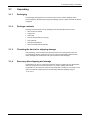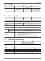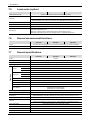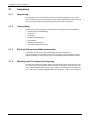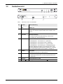
1
NRA-2500 NRA-3000 NRA-6000 Remote Spectrum Analyzer Operating Manual / Bedienungsanleitung NRA-2500 NRA-3000 NRA-6000 Remote Spectrum Analyzer Operating Manual Narda Safety Test Solutions GmbH Sandwiesenstraße 7 72793 Pfullingen, Germany © 2011 ® Names and Logo are registered trademarks of Narda Safety Test Solutions GmbH and L3 Communications Holdings, Inc. – Trade names are trademarks of the owners. Order no.: 3200/98.11 Issue: 02/01.2011, A ... Previous issue: 01/07.2010, A ... Subject to change. Our normal guarantee and delivery terms apply. Printed in Germany Contents Contents 1 2 Introduction..............................................................................3 1.1 About this device............................................................................. 4 1.1.1 NRA-2500 ........................................................................................4 1.1.2 NRA-3000 ........................................................................................4 1.1.3 1.2 NRA-6000 ........................................................................................4 About this operating manual ........................................................... 5 1.2.1 Symbols and terms used in warnings ..............................................5 1.2.2 Warning format ................................................................................5 1.2.3 Symbols and characters ..................................................................6 Important safety instructions .................................................7 2.1 2.2 2.3 2.4 2.5 2.6 3 4 Narda Using this operating manual ........................................................... 8 Before connecting up ...................................................................... 8 Proper use ...................................................................................... 8 Improper use................................................................................... 8 General hazards ............................................................................. 8 Faults and unusual stresses ........................................................... 9 Overview / Fitting / Connecting ............................................ 10 3.1 Unpacking ..................................................................................... 11 3.1.1 Packaging ......................................................................................11 3.1.2 Package contents ..........................................................................11 3.1.3 Checking the device for shipping damage.....................................11 3.1.4 Recovery after shipping and storage .............................................11 3.2 3.3 3.4 3.5 Device overview............................................................................ 12 Symbols on the device.................................................................. 13 Rack mounting .............................................................................. 13 Connecting up............................................................................... 14 Getting started ....................................................................... 15 4.1 General information ...................................................................... 16 4.1.1 USB connection via virtual COM port ............................................16 4.1.2 Ethernet link using crossover cable ...............................................16 4.1.3 Ethernet link via a network.............................................................17 4.2 4.3 4.4 4.5 4.6 4.7 4.8 Switching on.................................................................................. 17 Self test / Error codes ................................................................... 17 Determining remote interface ready status................................... 18 USB connection ............................................................................ 18 Firmware-Update .......................................................................... 19 Network configuration ................................................................... 19 Auxiliary and demo applications ................................................... 20 4.8.1 NRA Configurator and Device Finder ............................................20 4.8.2 Demo applications .........................................................................20 NRA-2500/3000/6000 1 Contents 4.8.3 5 Cleaning / Maintenance / Repairs / Disposal....................... 21 5.1 5.2 5.3 5.4 Cleaning........................................................................................ 22 Maintenance and repairs .............................................................. 22 Replacing the fuse ........................................................................ 22 Correct disposal ............................................................................ 23 6 Remote Control...................................................................... 24 7 Specifications ........................................................................ 25 8 7.1 7.2 Frequency ranges and modes ...................................................... 26 RF features ................................................................................... 26 7.2.1 Frequency ......................................................................................26 7.2.2 Amplitude .......................................................................................26 7.2.3 RF input .........................................................................................27 7.3 7.4 7.5 7.6 7.7 7.8 7.9 Spectrum analysis......................................................................... 27 Multi channel power (option)......................................................... 27 Level meter (option) ...................................................................... 28 General measurement functions................................................... 28 General specifications................................................................... 28 Declaration of origin ...................................................................... 29 CE Declaration of Conformity ....................................................... 30 Order information .................................................................. 32 8.1 8.2 9 2 Web server.....................................................................................20 Device versions............................................................................. 33 Options.......................................................................................... 33 Glossary ................................................................................. 34 NRA-2500/3000/6000 Narda 1 Introduction 1 Introduction This chapter contains basic information about using the NRA and about the structure of this Operating Manual. Narda 1.1 About this device (page 4) 1.2 About this operating manual (page 5) NRA-2500/3000/6000 3 1 Introduction 1.1 About this device The remote-controlled Spectrum Analyzer NRA (Narda Remote Spectrum Analyzer) is intended for measuring and analyzing as well as short- and long-term monitoring of all types of RF signals. The NRA is available in three versions, NRA-2500, NRA-3000 and NRA-6000, which meet the requirements of applications in satellite communications, broadcasting, and telecommunications. Optional extras allow users to adapt the range of functions to suit individual needs. The NRA is a rack-mounted unit fitted into a rugged 19” casing just one unit in height (1 HU = 1.75"). The device is characterized by its low power consumption of less than 20 W, which means that it also generates very little waste heat. The use of a precision heterodyne receiver coupled with modern digital signal processing means that the NRA can make accurate measurements very quickly. Operation and remote control of the NRA is by means of an ASCII-based command set that allows very efficient programming. All the available commands are described in detail in the NRA Command Reference Guide, which also contains comprehensively documented command sequences that make it easier to efficiently develop programs for remote control and operation of the device. 1.1.1 NRA-2500 The NRA-2500 was specially developed for measurement tasks in the field of satellite communications (SatCom). Its 5 MHz to 2500 MHz frequency range is tailored to the L-Band, allowing the NRA-2500 to monitor the intermediate frequencies and reference signals commonly used in satellite communications. 1.1.2 NRA-3000 The NRA-3000 is particularly suitable for measurement tasks involving broadcasting equipment. Signals with frequencies up to 3 GHz can be measured, and the maximum input level of +20 dBm means that the NRA-3000 can also handle the higher signal levels that are typically encountered in the field of broadcasting. 1.1.3 NRA-6000 The NRA-6000 is especially useful for measurements in telecommunications, such as wireless services up to 6 GHz. With its extremely large resolution bandwidth of up to 20 MHz, the NRA-6000 covers the entire frequency spectrum from 9 kHz up to 6 GHz. Here too, high input levels of up to +20 dBm can be measured and analyzed. 4 NRA-2500/3000/6000 Narda 1 Introduction 1.2 About this operating manual Various elements are used in this operating manual to indicate special meanings or particularly important instructions. 1.2.1 Symbols and terms used in warnings The following warnings, symbols and terms are used in this document in compliance with the American National Standard ANSI Z535.6-2006: This general danger symbol in conjunction with the terms CAUTION, WARNING, or DANGER warns of the risk of severe injury. Follow all subsequent instructions to avoid injury or death. Indicates a danger that could lead to damage or destruction of the device. NOTICE 1.2.2 CAUTION Indicates a danger that represents a low or medium risk of injury. WARNING Indicates a danger that could lead to death or severe injury. DANGER Indicates a danger that will result in death or severe injury. Warning format All warnings have the following format: WARNING TERM Type and source of danger Consequences of ignoring the warning ► Action needed to avoid danger Narda NRA-2500/3000/6000 5 1 Introduction 1.2.3 Symbols and characters Requirement Indicates a requirement that must be fulfilled before the subsequent action can be taken. Example: 9 9 The measurement screen is displayed. Action Indicates a single action. Example: ► ► Switch the device on. Sequence of actions Indicates a sequence of actions that must be performed in the order given. 1. 2. 3. ª Result Indicates the result of an action. Example: ª The device starts a self test. Bold text Control element or menu name Indicates device control elements and menu names. Example: ► Press the OK key. Note: 6 Important additional information or details of special features or situations. NRA-2500/3000/6000 Narda 2 Important safety instructions 2 Important safety instructions This chapter contains important information on how to handle the device safely. Narda 2.1 Using this operating manual (page 8) 2.2 Before connecting up (page 8) 2.3 Proper use (page 8) 2.4 Improper use (page 8) 2.5 General hazards (page 8) 2.6 Faults and unusual stresses (page 9) NRA-2500/3000/6000 7 2 Important safety instructions 2.1 Using this operating manual ► Please read this manual carefully and completely before using the device. ► Keep this manual so that it is readily available to all users of the device. ► Always make sure that this manual accompanies the device if it is given to a third party. 2.2 Before connecting up The device left the factory in perfect condition. We recommend that the following instructions be followed to ensure that this condition is maintained and that operation of the device is without danger. 2.3 Proper use The device may only be used under the conditions and for the purpose for which it was constructed. The NRA is designed for measuring and analyzing high frequency electrical signals. ► Only use the device under the conditions and for the purpose for which it was constructed. ► The device must only be used indoors and in dry conditions. ► Do not exceed the maximum permitted signal level for the device. Proper use also includes the following: ► Following the national accident prevention rules that apply at the place of use. ► Only allowing appropriately qualified and trained persons to use the device. 2.4 Improper use The device must not be used outdoors. 2.5 General hazards WARNING Electric shock High voltages are present inside the device. ► Do not open the device. (Opening the device invalidates all claims under warranty.) ► Do not handle the opened device or a device which is visibly damaged. ► Only use the accessories designed for the NRA and supplied with the device. WARNING Electric shock from liquid entering the device If liquid gets inside the device casing, there is a danger of potentially fatal electric shock and the device may be damaged or destroyed. ► Make sure that no liquid can get into the device. 8 NRA-2500/3000/6000 Narda 2 Important safety instructions WARNING Overvoltage Incorrect connectors and excessive voltages adversely affect the safety of the device and can endanger the user. ► This device is intended for use with the fixed electrical installation within a building complying with IEC 61010-1 overvoltage category II. Only use the device under the conditions specified in this standard. ► The inputs are not rated for connection to mains or overvoltage category II, III or IV circuits. WARNING Safety and malfunction Improper use, damage, and unauthorized repairs can affect the safety and function of the device. ► Only use the device under the conditions and for the purpose for which it was designed. ► Check the device for damage regularly. ► Make sure that any repairs are made only by qualified persons. CAUTION Hot connector sockets The connecting sockets (RF IN) on the back panel can get very warm if the device is used for long periods. This is normal. ► Please be careful when touching the connectors after using the device for a long period of time. NOTICE Overheating in rack Fitting the device in an unventilated rack may result in malfunctioning and damage. ► Make sure that the device is operated within the ambient temperature range stated in the specifications. ► Make sure that there is adequate space around the device and that there is sufficient ventilation. 2.6 Faults and unusual stresses Take the device out of service and secure it against unauthorized use if it can no longer be used safely, for example as in the following situations: • The device is visibly damaged. • The device does not work any more. Contact your local Sales Partner for assistance in such cases. Narda NRA-2500/3000/6000 9 3 Overview / Fitting / Connecting 3 Overview / Fitting / Connecting This chapter contains an overview of the NRA and describes how to fit it in a rack and how to connect it up. 10 3.1 Unpacking (page 11) 3.2 Device overview (page 12) 3.3 Symbols on the device (page 13) 3.4 Rack mounting (page 13) 3.5 Connecting up (page 14) NRA-2500/3000/6000 Narda 3 Overview / Fitting / Connecting 3.1 Unpacking 3.1.1 Packaging The packaging is designed to be re-used as long as it has not been damaged during previous shipping. Please keep the original packaging and use it again whenever the device is shipped. 3.1.2 Package contents Carefully remove all items from the packaging and check that all items are correct: • NRA version as ordered • Support CD • USB cable • AC line cord (according to country) • Test certificate • NRA Operating Manual • NRA Command Reference Guide 3.1.3 Checking the device for shipping damage After unpacking, check the device and all accessories for any damage that may have occurred during shipping. Damage may have occurred if the packaging itself has been clearly damaged. Do not attempt to use a device that has been damaged. 3.1.4 Recovery after shipping and storage Condensation can form on a device that has been stored or shipped at a low temperature when it is brought into a warmer environment. To prevent damage, wait until all condensation on the surface of the device has evaporated. The device is not ready for use until it has reached a temperature that is within the guaranteed operating range of -10 to +50 °C. Narda NRA-2500/3000/6000 11 3 Overview / Fitting / Connecting 3.2 Device overview POWER USB UPDATE 1 2 LAN LINK STATUS REMOTE SPECTRUM ANALYZER • NRA Line 20 W 100-240 VAC 50/60 Hz Fuse T 2.0A/250V 3 4 5 RF in 50 Ω Ethernet +27dBm max 50 VDC max 6 7 8 Figure 1: Overview of front and back panels Nr. Element Function / Description 1 USB Mini USB connector 2 UPDATE Activates a firmware update Information on updating the firmware is found in chapter 4.6 on page 19. 3 LAN LINK Network connection • LED glows green: Network connection detected • LED flashes green: Data transfer 4 STATUS Device status • Start up phase 1: LED glows red = System start • Start up phase 2: LED glows orange = Self test • Start up phase 3: LED glows red = Loading program • Start up phase 4: LED glows green = Ready *If an error occurs during the self test, the LED will flash red. The number of flashes indicates the type of error. Information about the error codes is found in chapter 4.3 on page 17. 12 5 POWER AC power switch The device is disconnected from AC power when the switch is set to 0. 6 Power AC power socket and fuses The fuses are in the fuse holder directly underneath the AC line socket. 7 Ethernet RJ45 Ethernet connector 8 RF in 50 Ω Signal input connector, 50 Ω N connector NRA-2500/3000/6000 Narda 3 Overview / Fitting / Connecting 3.3 Symbols on the device Symbol Description Refer to operating manual The operating manual contains important information about items marked with the general warning symbol. Compliance The CE mark indicates that the device complies with the requirements of the applicable European standards. Separate disposal This product is subject to the European Regulation 2002/96/EC governing the Disposal of Waste Electrical and Electronic Equipment (WEEE). 3.4 Rack mounting The device is designed to be mounted in a 19” rack. ► Make sure the device is secure when mounting it in the rack. NOTICE Overheating in rack Fitting the device in an unventilated rack may result in malfunctioning and damage. ► Make sure that the device is operated within the ambient temperature range stated in the specifications. ► Make sure that there is adequate space around the device and that there is sufficient ventilation. Narda NRA-2500/3000/6000 13 3 Overview / Fitting / Connecting 3.5 Connecting up WARNING Electric shock risk if device not grounded Operating this device from an AC line outlet without a ground connection can lead to a potentially fatal electric shock. ► Use only the AC line cord supplied with the device. ► Do not use the AC line cord if it is damaged. ► Do not connect the device to any AC power outlet that is not equipped with a protective ground. NOTICE Inaccessible AC line switch The device must be disconnected from the AC line by means of the AC power switch in an emergency. ► Make sure that you set up the device so that the AC power switch is easily accessible at all times. To connect up the device: ► Connect the device to the network using the Ethernet connection (Figure 1: 7). or Connect the device to a PC using the USB connection (Figure 1: 1). ► Connect the AC power input on the device (Figure 1: 6) to the AC power supply using the AC power cord supplied with the device. 14 NRA-2500/3000/6000 Narda 4 Getting started 4 Getting started This chapter describes how to start using the device. Narda 4.1 General information (page 16) 4.2 Switching on (page 17) 4.3 Self test / Error codes (page 17) 4.4 Determining remote interface ready status (page 18) 4.5 USB connection (page 18) 4.6 Firmware-Update (page 19) 4.7 Network configuration (page 19) 4.8 Auxiliary and demo applications (page 20) NRA-2500/3000/6000 15 4 Getting started 4.1 General information The device can be addressed for control via the remote interface by means of a USB connection and / or an Ethernet (TCP) connection. The USB interface appears as a socalled virtual COM port on the PC and allows simple handling just like the usual serial interface. The NRA internal TCP server allows connection to a client for exchanging data. The IP address and the remote port of the TCP server must be known in order to set up the Ethernet link. The IP address and port together with the communication protocol are also called the socket interface. The entire range of functions is available via the remote interface. You can set all the measurement parameters and read out the measurement results cyclically. NOTE: 4.1.1 Every command sent to the remote device generates a response. The time taken for the response to come from the remote device depends greatly on the type of command. Commands received in parallel (e.g. from USB and Ethernet) are processed sequentially in the remote device. USB connection via virtual COM port One USB client is always connected to the USB host via the USB connection. No provision has been made for multiple client connections to one remote device. 4.1.2 Ethernet link using crossover cable You can directly connect a remote device to a computer using a crossover network cable. Static IP addresses must be assigned to the client and the server for this, as the remote device is not equipped with a DHCP server. In this instance, only one client can be connected to the TCP server of the remote device. 16 NRA-2500/3000/6000 Narda 4 Getting started 4.1.3 Ethernet link via a network Indirect access via a network is achieved by connecting the remote device to a network. The IP address can be assigned dynamically by a DHCP server (e.g. built in to a router) or statically. A plain Ethernet (patch) cable is required. 4.2 Switching on 9 Make sure that all the connections have been made correctly (see Chapter 3.5 on page 14). ► Switch the device on using the AC power switch: ª Start up phase 1: Status LED glows red = System start ª Start up phase 2: Status LED glows orange = Self test* ª Start up phase 3: Status LED glows red = Loading program ª Start up phase 4: Status LED glows green = Ready If the Ready status is not indicated within about 1 minute: ► Switch the device off and then repeat the switch on process. NOTE: If the device repeatedly does not switch on, please contact your local representative for Narda products. *If an error occurs during the self test, the LED will flash red. The number of flashes indicates the type of error. Information about the error codes is found in the next section. 4.3 Self test / Error codes If an error occurs during the self test, the LED will flash red. The number of flashes indicates the type of error. The sequence of flashes is repeated three times at intervals of three seconds. Table 1: Error codes Number of flashes Narda Error 1 Operating system 2 Hardware 3 Memory 4 Data Logger 5 Flash 6 Battery NRA-2500/3000/6000 17 4 Getting started 4.4 Determining remote interface ready status The Status LED glows green as soon as the boot process is completed and the communication function is working for the remote interfaces (USB / Ethernet). This process takes at least 20 seconds. To check the communications function of the remote interface(s) it is a good idea to keep transmitting the REMOTE?; command until the device responds. 4.5 USB connection The USB connection can be used for the following tasks: • Configuring the device • Uploading firmware updates • Monitoring (retrieving the measurement screen) NOTE: The USB connection is of only limited use for controlling measurements because the input is not electrically decoupled. Only use the Ethernet connection for controlling measurements to ensure that the specifications are not impaired. You will have to install the USB driver for the device before you can use the USB connection. ► To do this, start the Setup program (setup.exe) from the USB_Driver_NRA folder on the Support CD. On successful installation of the USB connection, a (virtual) COM port is shown in the Device Manager of the host computer. Communication with the device is via this virtual COM port which acts just like a normal serial interface. The following interface parameters are used: Table 2: 18 USB interface parameters Parameter Settings Baud rate 115200 Baud Start bits 1 Data bits 8 Stop bits 1 Parity None Handshake None NRA-2500/3000/6000 Narda 4 Getting started 4.6 Firmware-Update NOTE: The firmware can only be updated via the USB interface. Information about the latest firmware updates can be found on the NRA product web page (www.narda-sts.com). To update the firmware: 1. Activate Update mode on the NRA: Use e.g. the tip of a ballpoint pen to press and hold down button (Figure 1: 2) on the front panel and switch the device on using the AC power switch (Figure 1: 5). ª The Status LED (Figure 1: 4) glows red continuously in Update mode. 2. Connect the NRA to a free USB socket on your PC. 3. Follow the instructions given about NRA firmware updates on the website to upload the new firmware to the NRA device. 4.7 Network configuration The device operates as a TCP server and can accept a connection to a client. ► When starting up, make sure that the device is in the same subnet as the operating computer and that there are no firewalls or other network components that might prevent data communications. A DHCP server (e.g. in the form of a router) must be present in the network if automatic IP address assignment (DHCP service) is to be used. The default settings are shown in the table below. Table 3: NOTE: Narda Default parameters for TCP server network configuration Parameter Default settings DHCP OFF IP address 192.168.128.128 Subnet mask 255.255.255.0 Gateway - DNS - TCP port 55555 If you want to use settings other than the default settings, you can use the „NRA Configurator“ application on the Support CD for this purpose. NRA-2500/3000/6000 19 4 Getting started 4.8 Auxiliary and demo applications This section gives a brief summary of the auxiliary and demo applications that are on the Support CD. The applications are described in detail in electronic form on the Support CD. 4.8.1 NRA Configurator and Device Finder The Configurator is primarily intended for network configuration of the device. The Device Finder is intended for detecting NRA devices and its IP addresses in the network (this function is not available for USB). 4.8.2 Demo applications The demo applications on the Support CD have the following features: • They demonstrate the performance of the remote interface of the device. • They help you in taking the first steps in familiarizing yourself with the device. • Separate demo applications are available for each operating mode. 4.8.3 Web server The web server is an integral part of the NRA device with the following functions: • It enables communication with the device using a standard web browser. • No PC application installation is required. • It enables access to the HTML pages stored in the device. • Java applets are being used 20 NRA-2500/3000/6000 Narda 5 Cleaning / Maintenance / Repairs / Disposal 5 Cleaning / Maintenance / Repairs / Disposal This chapter contains information about how to clean the device, how to replace the fuses, and how to dispose of the device when it is to be scrapped. Narda 5.1 Cleaning (page 22) 5.2 Maintenance and repairs (page 22) 5.3 Replacing the fuse (page 22) 5.4 Correct disposal (page 23) NRA-2500/3000/6000 21 5 Cleaning / Maintenance / Repairs / Disposal 5.1 Cleaning WARNING Electric shock risk from liquid entering the device Liquid getting inside the device casing can lead to a potentially fatal electric shock and can damage or destroy the device. ► Do not let water or cleaning fluid get inside the device. ► Use only a slightly damp cloth for cleaning the device. 5.2 Maintenance and repairs There are no user-replaceable or serviceable parts in the device. ► Please contact your local representative for Narda products in the event of a problem. 5.3 Replacing the fuse Both phases of the AC supply to the device are fuse protected. Both the fuses (size 5 x 20 mm) are located in the fuse holder directly underneath the AC line connector on the back panel of the device: Line 20 W 100-240 VAC 50/60 Hz Fuse T 2.0A/250V 1 Figure 2: Fuses are located underneath the AC line connector. To change the fuses: 1. Switch off the device using the AC power switch, and unplug the AC line cord from the device. 2. Use a small screwdriver to lift out the fuse holder (1). 3. Remove the defective fuse or fuses and replace it or them with fuses of the same type and rating. Information about the correct type of fuse is printed on the back panel of the device. 4. Push the fuse holder back in to the casing, reconnect the AC line cord, and switch the device on again. 22 NRA-2500/3000/6000 Narda 5 Cleaning / Maintenance / Repairs / Disposal 5.4 Correct disposal The NRA is a high quality device that should have a long operating life. Nevertheless, at some point, it too will come to the end of its useful life. Please remember that you must dispose of electrical equipment in the proper way. The NRA complies with the WEEE Guideline of the European Union (2002/96/EC) and comes under Category 9 (Monitoring and Test Instruments). As the manufacturer of this device, we offer you the following service: You can return the device to us free of charge and we will ensure its correct disposal according to environmental regulations. You can obtain more information about this from your local Narda Sales Partner or from our web site under www.narda-sts.de. Narda NRA-2500/3000/6000 23 6 Remote Control 6 Remote Control Detailed information about remote control together with descriptions of the remote control commands and application examples can be found in the separate Command Reference Guide supplied with the device. 24 NRA-2500/3000/6000 Narda 7 Specifications 7 Specifications This chapter contains the specifications of the NRA. Unless otherwise stated, the quoted specifications apply only within the temperature range 20 °C to 26 °C and relative humidity between 25 % and 75 %. The device must be switched on for at least 30 minutes before the specifications can be checked. All specifications are valid only for remote control using the Ethernet interface. All data are subject to change without notice. Narda 7.1 Frequency ranges and modes (page 26) 7.2 RF features (page 26) 7.3 Spectrum analysis (page 27) 7.4 Multi channel power (option) (page 27) 7.5 Level meter (option) (page 28) 7.6 General measurement functions (page 28) 7.7 General specifications (page 28) 7.8 Declaration of origin (page 29) 7.9 CE Declaration of Conformity (page 30) NRA-2500/3000/6000 25 7 Specifications 7.1 Frequency ranges and modes NRA-2500 Frequency range 5 MHz to 2.5 GHz NRA-6000 9 kHz to 3 GHz 9 kHz to 6 GHz Spectrum Analysis Level Meter (option) Multi Channel Power (option) Modes 7.2 RF features 7.2.1 Frequency NRA-2500 NRA-3000 Resolution bandwidth (RBW) Phase noise (SSB) NRA-3000 NRA-6000 See specifications for each mode a), 10 kHz carrier spacing < - 70 dBc (RBW = 1 Hz) 300 kHz carrier spacing < - 100 dBc (RBW = 1 Hz) Initial deviation: < 1.0 ppm Aging: < 5 ppm over 15 years Thermal drift: < 1.5 ppm (within specified operating temperature range) Reference frequency a) Verification at 57.5 MHz; 2140.5 MHz and 4500.5 MHz (NRA-6000) 7.2.2 Amplitude NRA-2500 Reference level (RL) from NRA-3000 NRA-6000 -30 dBm (in 1 dB steps) to Display range 0 dBm +20 dBm -110 dBm to 0 dBm -130 dBm to +20 dBm 1 dB above the measurement range 0 to 30 dB in steps of 1 dB (coupled with RL) RF attenuation Maximum RF power level 0 to 50 dB in steps of 1 dB (coupled with RL) 27 dBm (destruction limit) Maximum DC voltage 50 V < - 130 dBm or < RL - 100 dB f ≤ 30 MHz Intrinsic noise RBW = 1 kHz b) < - 110 dBm or < RL - 80 dB < - 126 dBm or < RL - 96 dB f ≤ 2 GHz < - 125 dBm or < RL - 95 dB f ≤ 3 GHz 3rd order intermodulation products Extended level measurement uncertainty Spurious responses b), c) (input related) Spurious responses (residual) b) < - 130 dBm or < RL - 100 dB f ≤ 30 MHz < - 126 dBm or < RL - 96 dB f ≤ 2 GHz < - 125 dBm or < RL - 95 dB f ≤ 4 GHz < - 120 dBm or < RL - 90 dB f ≤ 6 GHz < -60 dBc for two single signals of level 6 dB below RL and a spectral line spacing of more than 1 MHz < ± 1.5 dB < ± 1.2 dB < -50 dBc or RL -50 dB < -60 dBc or RL -60 dB < -80 dBc or RL -50 dB < -90 dBm or RL -60 dB except for the frequency range 294 to 306 MHz and 4534 to 4586 MHz, where the value is < -85 dBm or RL -55 dB b) Whichever is worse c) Frequency separation to carrier (df) > 1 MHz 26 NRA-2500/3000/6000 Narda 7 Specifications 7.2.3 RF input NRA-2500 NRA-3000 Type Return loss NRA-6000 N-connector, 50 Ω b), d) > 10 dB for 1 kHz RBW, and RL ≥ -28 dBm > 12 dB for 1 kHz RBW, and RL ≥ -28 dBm > 12 dB for 1 kHz RBW, f ≤ 4.5 GHz and RL ≥ -28 dBm > 10 dB for 1 kHz RBW, f > 4.5 GHz and RL ≥ -28 dBm b) Whichever is worse d) Typical values 7.3 Spectrum analysis Frequency span NRA-2500 NRA-3000 NRA-6000 10 kHz to 2.495 GHz 1 kHz to 2.999 GHz 1 kHz to 5.999 GHz Measurement principle Spectrum analysis Set individually from a list or using the “MR Search” function for determining the optimum measurement range at a given time Measurement range setting (MR) Resolution bandwidths (RBW) (-3 dB) (list depends on selected sweep SPAN) 1 kHz to 1 MHz in steps of 1, 2, 3, 5,10, 20 Video bandwidth (VBW) 10 Hz to 20 MHz (in steps of 1, 2, 3, 5, 10, 20) 0.2 Hz to 2 MHz (depending on the selected RBW) Sweep time (typically, without communication) < 130 ms for Span = 1 GHz and RBW = 1 MHz (2001 samples for one Result Type) < 15 ms for Span = 50 MHz and RBW = 500 kHz (201 samples for one Result Type) Type Filter Gaussian Shape factor (-3 dB / 60 dB) <3.8 (for RBW ≤ 100 kHz) ACT: MAX: AVG: Displays current (actual) spectrum Maximum hold function Average over a selectable number of spectra (4 to 256) or a selectable time period (1 to 30 minutes) Max AVG: Maximum hold function after averaging over a defined number of spectra Min Minimum hold function Min AVG: Minimum hold function after averaging over a defined number of spectra Result Type 7.4 Multi channel power (option) NRA-2500 Measurement principle Resolution bandwidths RBW (-3 dB) Detection NRA-3000 NRA-6000 Spectrum analysis followed by integration over user-defined frequency bands (“services” 1 to 500) Auto: automatically set depending on the narrowest user-defined service bandwidth Manual: user-defined for all services Individual: separately defined for each individual service Root mean square value (RMS), RMS (integration time ≈ 1 ) RBW Filter See Spectrum Analysis mode Result Type See Spectrum Analysis mode Others On / Off Narda Measurement of services and gaps in the Service Table (Others = On) or measurement of services in the Service Table excluding gaps (Others = Off) NRA-2500/3000/6000 27 7 Specifications 7.5 Level meter (option) NRA-2500 Measurement principle NRA-3000 NRA-6000 Selective level measurement at a fixed frequency setting Peak Detection Root mean square value (RMS), RMS (integration time = 480 ms, observation time selectable from 480 ms up to 30 min) Filter Type Steep cutoff channel filter Resolution bandwidth RBW (-6 dB) 40 kHz to 32 MHz (10 steps per decade) Video bandwidth (VBW) Peak ACT: Peak MAX: RMS ACT: RMS MAX: Result Type 7.6 4 Hz to 32 MHz (depending on the selected RBW) Displays the current (actual) value Max hold function Averaging over a defined time period (0.48 seconds to 30 min) Max hold function over the averaged values – with RMS detector only General measurement functions NRA-2500 Setups Up to 27000 samples (data points) per Result Type and Sweep General specifications NRA-2500 NRA-3000 Usage ASCII based command sets Web server Supports Java Applet and HTML Operating temperature range Storage Climatic Compliance -10 °C to +50 °C 1K3 (IEC 60721-3) extended to -10 °C to +50 °C Transport 2K4 (IEC 60721-3) Operating 7K2 (IEC 60721-3) extended to -10 °C to +50 °C Storage Mechanical NRA-6000 Indoors Remote access 1M3 (IEC 60721-3) Transport 2M3 (IEC 60721-3) Operating 7M3 (IEC 60721-3) ESD and EMC EN 61326 -1: 2006 Dust and water resistance Safety Overvoltage EU Guidelines IP 50 EN 61010-1: 2002 This product is designed for INSTALLATION CATEGORY II per IEC 61010-1, respectively. 2003/11/EG 06.02.2003 (PBDE and OBDE) 2002/95/EG 27.01.2003 (RoHS) 2002/96/EG 27.01.2003 (WEEE) CE (European Community) approval Air humidity (operating range) RF Dimensions Yes < 29 g/m³ (< 93% at +30 °C) Standard EIA Rack Unit (1RU): 482 mm (19" w) x 45 mm (1.75" h) x 362 mm (14.3" d) Weight Interface Status information Power supply < 5 kg USB mini B (USB 2.0) on the front panel – for programming/debugging and updates Ethernet (10/100BaseT) on the rear panel – optical isolated for measurement control System-LED (bicolored) and LAN (single-colored) 100 to 240 V (AC) (50/60Hz) Power consumption < 20 W Recommended calibration interval 28 NRA-6000 Complete device configurations can be saved in the basic unit; up- and downloadable Trace Data 7.7 NRA-3000 24 months NRA-2500/3000/6000 Narda 7 Specifications 7.8 Declaration of origin Country of origin Narda Germany NRA-2500/3000/6000 29 7 Specifications 7.9 30 CE Declaration of Conformity NRA-2500/3000/6000 Narda 7 Specifications Narda NRA-2500/3000/6000 31 8 Order information 8 Order information This chapter contains the information for ordering the NRA. All information is subject to change without notice. 32 8.1 Device versions (page 33) 8.2 Options (page 33) NRA-2500/3000/6000 Narda 8 Order information 8.1 8.2 Device versions NRA-2500 Remote Analyzer, 5 MHz – 2.5 GHz 3201/101 NRA-3000 Remote Analyzer, 9 kHz – 3 GHz 3202/101 NRA-6000 Remote Analyzer, 9 kHz – 6 GHz 3203/101 Options Option, Multi Channel Power 3200/95.01 Option, Level Meter 3200/95.02 Option, Calibration Report Narda NRA-2500/3000/6000 NRA-2500 NRA-3000 NRA-6000 CAL3201/01 CAL3202/01 CAL3203/01 33 9 Glossary 9 Glossary Terms and abbreviations and their meanings are described in this section. 34 Term / Abbreviation Meaning Explanation AM Amplitude modulation Modulation method (used e.g. for radio broadcasting) Avg Average The measured values are averaged over a specific number or a specific time period. The resulting value (also called the RMS value) is displayed. BOS Authorities and organizations concerned with security (Behörden und Organisationen mit Sicherheitsaufgaben) BOS radio is a non-public mobile VHF terrestrial radio service in Germany (police, technical assistance, customs, fire brigades, rescue services, etc.). Tetra is a sub-group of BOS. DVB-T Digital Video Broadcasting Terrestrial Terrestrial earth-bound propagation of digital TV signals. Fcent Center frequency Center frequency in a frequency range FM Frequency modulation Modulation method Fmax Upper limit frequency Upper frequency in a frequency range Fmin Lower limit frequency Lower frequency in a frequency range Fspan Sweep span Frequency band symmetrical above and below the center frequency Fcent Full Span Full bandwidth All frequency values set by Fmin, Fmax, Fcent or Fspan are set to the largest possible frequency range that is permitted by the antenna or cable used or by the NRA. GPRS General Packet Radio Service Packet-switched data communications service in GSM networks. GSM Global System for Mobile Communications Standard for fully digital mobile networks used mainly for telephony but also for circuit- and packet switched data communications. ICNIRP International Commission on NonIonizing Radiation Protection) International, independent association of scientists researching the effects of nonionizing radiation on human health. NRA-2500/3000/6000 Narda 9 Glossary Measurement of radiation propagated equally in all directions in three-dimensional space. Isotropic measurement Max Maximum Maximum value of all the measured values Max Avg Maximum Average Maximum value of all the averaged measured values Min Minimum Minimum value of all the measured values Min Avg Minimum Average Minimum value of all the averaged measured values P-CPICH Primary Common Pilot Channel UMTS control channel RBW Resolution bandwidth Ability to distinguish between signals. Only signals with frequency differences greater than the defined resolution bandwidth can be distinguished from each other. A correspondingly small RBW must be chosen for measuring signals that are very close together in frequency. A larger RBW can be selected for measuring broadband signals. The indicated level will be too low if the RBW is too small. Individual signals cannot be separated if the RBW is too large. Result Type Result (evaluation) type Defines how the values recorded are evaluated. RL Reference Level The system sensitivity depends on the input attenuator setting. This is determined by the Reference Level. High measurement sensitivity avoids falsification of the results due to intrinsic noise. Tetra Terrestrial trunked radio Standard for digital trunked radio used as a universal platform for various mobile wireless services for users with special security needs, such as BOS, industry, public transport, airports, military, etc. UMTS Universal Mobile Telecommunications System Third-generation mobile wireless standard (3G) VBW Video bandwidth The VBW is used to smooth signals, generally to reduce noise. The selected VBW affects the sweep time. The smaller the VBW, the greater the smoothing of noise but the longer the sweep time. When measuring unknown signals, the VBW should be reduced in stages from the largest to the smallest value. WiMax Worldwide Interoperability for Microwave Access Radio system defined by IEEE Standard 802.16 for both fixed locations (e.g. radio links) and mobile devices. WLAN Wireless Local Area Network Wireless local area radio network defined by the IEEE-802.11 standard. Narda NRA-2500/3000/6000 35 NRA-2500 NRA-3000 NRA-6000 Remote Spectrum Analyzer Bedienungsanleitung Narda Safety Test Solutions GmbH Sandwiesenstraße 7 72793 Pfullingen, Deutschland © 2011 ® Namen und Logo sind eingetragene Markenzeichen der Narda Safety Test Solutions GmbH und L3 Communications Holdings, Inc. – Handelsnamen sind Markenzeichen der Eigentümer. Bestell-Nr.: 3200/98.11 Ausgabe: 02/01.2011, A ... Frühere Ausgabe: 01/07.2010, A ... Änderungen vorbehalten. Es gelten unsere normalen Garantie- und Lieferbedingungen. Printed in Germany Inhaltsverzeichnis Inhaltsverzeichnis 1 2 3 4 Narda Einleitung .................................................................................3 1.1 Zu diesem Gerät ............................................................................. 4 1.1.1 NRA-2500 ........................................................................................4 1.1.2 NRA-3000 ........................................................................................4 1.1.3 NRA-6000 ........................................................................................4 1.2 Zu dieser Bedienungsanleitung ...................................................... 5 1.2.1 Symbole und Warnworte in Warnhinweisen ....................................5 1.2.2 Aufbau der Warnhinweise................................................................5 1.2.3 Symbole und Textauszeichnungen..................................................6 Wichtige Sicherheitshinweise ................................................7 2.1 Verwenden dieser Bedienungsanleitung ........................................ 8 2.2 Vor dem Anschließen...................................................................... 8 2.3 Bestimmungsgemäßer Gebrauch................................................... 8 2.4 Nicht bestimmungsgemäßer Gebrauch .......................................... 8 2.5 Allgemeine Gefahren ...................................................................... 8 2.6 Fehler und außergewöhnliche Belastungen ................................. 10 Übersicht / Einbau / Anschluss ............................................ 11 3.1 Auspacken .................................................................................... 12 3.1.1 Verpackung....................................................................................12 3.1.2 Lieferumfang ..................................................................................12 3.1.3 Gerät auf Transportschäden untersuchen .....................................12 3.1.4 Erholung nach Transport und Lagerung ........................................12 3.2 Geräteübersicht ............................................................................ 13 3.3 Symbole am Gerät ........................................................................ 14 3.4 Einbau ........................................................................................... 14 3.5 Anschluss...................................................................................... 15 Inbetriebnahme...................................................................... 16 4.1 Allgemeine Hinweise..................................................................... 17 4.1.1 USB-Verbindung über virtuellen COM-Port ...................................17 4.1.2 Ethernet-Anbindung mit Crossover-Kabel .....................................17 4.1.3 Ethernet-Anbindung über ein Netzwerk.........................................18 4.2 Einschalten ................................................................................... 18 4.3 Selbsttest / Fehlercodes ............................................................... 18 4.4 Betriebsbereitschaft der Remote-Schnittstelle feststellen ............ 19 4.5 USB-Verbindung ........................................................................... 19 4.6 Firmware-Update .......................................................................... 20 4.7 Netzwerkkonfiguration .................................................................. 20 NRA-2500/3000/6000 1 Inhaltsverzeichnis 5 Hilfs- und Demoprogramme.......................................................... 21 4.8.1 Hilfsprogramme NRA-Configurator und Device Finder .................21 4.8.2 Demoprogramme ...........................................................................21 4.8.3 Webserver......................................................................................21 Reinigung / Wartung / Reparatur / Entsorgung................... 22 5.1 Reinigung...................................................................................... 23 5.2 Wartung und Reparatur ................................................................ 23 5.3 Gerätesicherung auswechseln ..................................................... 23 5.4 Fachgerechte Entsorgung ............................................................ 24 6 Fernsteuerung ....................................................................... 25 7 Technische Daten .................................................................. 26 8 9 2 4.8 7.1 Allgemeine Daten.......................................................................... 27 7.2 Ursprungserklärung ...................................................................... 27 Bestellangaben ...................................................................... 28 8.1 Geräteausführungen ..................................................................... 29 8.2 Optionen ....................................................................................... 29 Glossar ................................................................................... 30 NRA-2500/3000/6000 Narda 1 Einleitung 1 Einleitung Dieses Kapitel gibt grundlegende Hinweise zum Einsatz des NRA sowie zum Aufbau dieser Bedienungsanleitung. Narda 1.1 Zu diesem Gerät (Seite 4) 1.2 Zu dieser Bedienungsanleitung (Seite 5) NRA-2500/3000/6000 3 1 Einleitung 1.1 Zu diesem Gerät Der fernsteuerbare Spektrum Analysator NRA (Narda Remote Spectrum Analyzer) ist für die Messung, Analyse sowie Kurz- und Langzeitbeobachtung aller Arten von RF-Signalen geeignet. Den NRA gibt es in den Modellvarianten NRA-2500, NRA-3000 und NRA-6000, die unter anderem die Anforderungen der Anwendungsbereiche Satellitenkommunikation, Rundfunk und Telekommunikation erfüllen. Optionale Erweiterungen ermöglichen dem Anwender eine individuelle Anpassung des Funktionsumfangs. Der NRA ist ein Einbaugerät in stabilem 19-Zoll-Gehäuse mit nur einer Höheneinheit (1 HE = 1,75 Zoll). Das Gerät zeichnet sich durch seine geringe Leistungsaufnahme von weniger als 20 Watt aus und erzeugt daher nur geringe Abwärme. Durch die Verwendung eines präzisen Überlagerungsempfängers und die moderne digitale Signalverarbeitung sind mit dem NRA genaue und sehr schnelle Messungen möglich. Die Bedienung und Fernsteuerung des NRA erfolgt über einen ASCII-basierten Befehlssatz, der ein sehr effizientes Programmieren erlaubt. Im NRA Command Reference Guide sind alle verfügbaren Kommandos detailliert beschrieben. Dort finden Sie auch ausführlich dokumentierte Befehlssequenzen, die eine effektive Entwicklung von Fernsteuer- und Fernbedienungsprogrammen erleichtern. 1.1.1 NRA-2500 Der NRA-2500 wurde speziell für Messaufgaben in der Satellitenkommunikation (SatCom) entwickelt. Mit einem auf das L-Band zugeschnittenen Frequenzbereich von 5 MHz bis 2500 MHz erlaubt der NRA-2500 die Überwachung der im Satellitenmarkt gebräuchlichen Zwischenfrequenzen und der Referenzsignale. 1.1.2 NRA-3000 Der NRA-3000 eignet sich besonders gut für Messaufgaben an Rundfunksendeanlagen (Broadcast). Es können Signale mit Frequenzen bis zu 3 GHz gemessen werden. Mit einem maximalen Eingangspegel von +20 dBm kann der NRA-3000 auch die höheren Signalpegel bewältigen, die im Rundfunkbereich typischerweise auftreten. 1.1.3 NRA-6000 Der NRA-6000 eignet sich besonders gut für Messaufgaben in der Telekommunikation, z.B. für Funkdienste bis 6 GHz (Wireless). Mit einer extrem großen Auflösungsbrandbreite von bis zu 20 MHz deckt der NRA-6000 das gesamte Frequenzspektrum von 9 kHz bis 6 GHz ab. Es können auch hohe Eingangspegel bis +20 dBm gemessen und analysiert werden. 4 NRA-2500/3000/6000 Narda 1 Einleitung 1.2 Zu dieser Bedienungsanleitung In dieser Bedienungsanleitung werden verschiedene Elemente verwendet, um auf besondere Textbedeutungen oder besonders wichtige Textstellen hinzuweisen. 1.2.1 Symbole und Warnworte in Warnhinweisen Entsprechend dem American National Standard ANSI Z535.6-2006 werden in diesem Dokument folgende Warnhinweise, Symbole und Warnworte verwendet: Das allgemeine Gefahrensymbol warnt in Verbindung mit den Warnworten VORSICHT, WARNUNG und GEFAHR vor dem Risiko ernster Verletzungen. Befolgen Sie alle nachfolgenden Hinweise, um Verletzungen oder Tod zu vermeiden. ACHTUNG Weist auf eine Gefahr hin, die zur Beschädigung oder Zerstörung des Gerätes führt. VORSICHT Weist auf eine Gefahr hin, die ein geringes oder mittleres Verletzungsrisiko darstellt. WARNUNG Weist auf eine Gefahr hin, die zum Tod oder zu schweren Verletzungen führen kann. Weist auf eine Gefahr hin, die unmittelbar zum Tod oder zu schweren Verletzungen führt. GEFAHR 1.2.2 Aufbau der Warnhinweise Alle Warnhinweise sind wie folgt aufgebaut: WARNWORT Art und Quelle der Gefahr Folgen bei Nichtbeachtung ► Handlung zur Gefahrenabwehr Narda NRA-2500/3000/6000 5 1 Einleitung 1.2.3 Symbole und Textauszeichnungen Voraussetzung 9 Kennzeichnet eine Voraussetzung, die erfüllt sein muss, bevor eine nachfolgende Handlung ausgeführt wird, z. B. 9 Sie befinden sich in der Messanzeige. Handlungsschritt ► Kennzeichnet einen einzelnen Handlungsschritt, z. B. ► Gerät einschalten. Handlungsfolge 1. 2. 3. Kennzeichnet eine Abfolge von Handlungsschritten, die in der gegebenen Reihenfolge ausgeführt werden müssen. ª Resultat Kennzeichnet das Ergebnis einer Handlung, z. B. ª Das Gerät startet einen Selbsttest. Fette Schrift Bedienelement oder Menüname Kennzeichnet Bedienelemente des Gerätes und Menüname, z. B. ► Taste OK drücken. Hinweis: 6 Wichtige Zusatzinformationen oder Hinweise auf Besonderheiten und Sonderfälle. NRA-2500/3000/6000 Narda 2 Wichtige Sicherheitshinweise 2 Wichtige Sicherheitshinweise Dieses Kapitel gibt wichtige Hinweise zum sicheren Umgang mit dem Gerät. Narda 2.1 Verwenden dieser Bedienungsanleitung (Seite 8) 2.2 Vor dem Anschließen (Seite 8) 2.3 Bestimmungsgemäßer Gebrauch (Seite 8) 2.4 Nicht bestimmungsgemäßer Gebrauch (Seite 8) 2.5 Allgemeine Gefahren (Seite 8) 2.6 Fehler und außergewöhnliche Belastungen (Seite 10) NRA-2500/3000/6000 7 2 Wichtige Sicherheitshinweise 2.1 Verwenden dieser Bedienungsanleitung ► Lesen Sie diese Bedienungsanleitung aufmerksam und vollständig, bevor Sie mit dem Gerät arbeiten. ► Bewahren Sie diese Bedienungsanleitung so auf, dass sie allen Benutzern beim Arbeiten mit dem Gerät stets zur Verfügung steht. ► Geben Sie das Gerät immer nur gemeinsam mit dieser Bedienungsanleitung an Dritte weiter. 2.2 Vor dem Anschließen Dieses Gerät hat das Werk in einwandfreiem Zustand verlassen. Zur Erhaltung dieses Zustandes und eines gefahrlosen Betriebes empfehlen wir, die nachfolgenden Hinweise zu beachten. 2.3 Bestimmungsgemäßer Gebrauch Das Gerät darf nur unter den Bedingungen und für die Zwecke eingesetzt werden, für die es konstruiert wurde. Der NRA dient zur Messung und Analyse hochfrequenter elektrischer Signale. ► Setzen Sie das Gerät nur unter den Bedingungen und für die Zwecke ein, für die es konstruiert wurde. ► Das Gerät darf nur in trockenen Räumen betrieben werden. ► Überschreiten Sie nicht die maximal zulässigen Signalpegel des Gerätes. Bestimmungsgemäßer Gebrauch bedeutet auch folgendes: ► Beachten Sie die nationalen Unfallverhütungsvorschriften am Einsatzort. ► Nur entsprechend qualifiziertes und geschultes Fachpersonal darf das Gerät bedienen. 2.4 Nicht bestimmungsgemäßer Gebrauch Das Gerät darf nicht im Freien betrieben werden. 2.5 Allgemeine Gefahren WARNUNG Stromschlag Im Inneren des Gerätes treten teilweise hohe Spannungen auf. ► Öffnen Sie das Gerät nicht. (Durch das Öffnen des Gerätes erlischt jeglicher Garantieanspruch.) ► Hantieren Sie nicht mit einem geöffneten oder erkennbar beschädigten Gerät. ► Verwenden Sie nur für das NRA vorgesehene, mitgelieferte Zubehörteile. 8 NRA-2500/3000/6000 Narda 2 Wichtige Sicherheitshinweise WARNUNG Stromschlag durch eindringende Flüssigkeiten In das Gehäuse eindringende Flüssigkeiten können zu einem lebensgefährlichen Stromschlag und zur Beschädigung oder Zerstörung des Gerätes führen. ► Stellen Sie sicher, dass keine Flüssigkeiten in das Gerät eindringen können. WARNUNG Überspannung Eine falsche Anschlussart und Überspannungen beeinträchtigen die Sicherheit des Gerätes und können den Benutzer gefährden. ► Dieses Gerät ist zum Anschluss an die feste elektrische Installation eines Gebäudes nach IEC 61010-1 Überspannungskategorie II vorgesehen. Betreiben Sie das Gerät nur unter den dort genannten Bedingungen. ► Die Geräteeingänge sind nicht geeignet für den Anschluss an das Stromnetz oder Netze der Überspannungskategorie II, III oder IV. WARNUNG Sicherheit und Fehlfunktion Unsachgemäßer Gebrauch, Beschädigungen und unerlaubte Reparaturen können die Sicherheit und Funktion des Gerätes beeinträchtigen. ► Betreiben Sie das Gerät nur unter den Bedingungen und für die Zwecke, für die es konstruiert wurde. ► Kontrollieren Sie das Gerät regelmäßig auf Beschädigungen. ► Lassen Sie Reparaturen nur durch Fachkräfte ausführen. VORSICHT Erwärmung der Anschlussbuchsen Bei längerem Betrieb kann die Anschlussbuchse (RF in) an der Geräterückseite sehr warm werden. Hierbei handelt es sich nicht um eine Fehlfunktion. ► Seien Sie vorsichtig, wenn Sie nach längerem Betrieb die Anschlussbuchse anfassen. ACHTUNG Überhitzung im Rack Der Einbau in ein unbelüftetes Rack-Gehäuse kann zu Funktionsstörungen und Beschädigungen führen. ► Halten Sie die in den technischen Daten genannten Umgebungstemperaturen ein. ► Sorgen Sie für genügend Raum um das Gerät und für ausreichende Belüftung. Narda NRA-2500/3000/6000 9 2 Wichtige Sicherheitshinweise 2.6 Fehler und außergewöhnliche Belastungen Setzen Sie das Gerät außer Betrieb und sichern Sie es gegen unbefugte Benutzung, wenn ein gefahrloser Betrieb nicht mehr möglich ist, wie z. B. in folgenden Fällen: • Das Gerät weist sichtbare Beschädigungen auf. • Das Gerät funktioniert nicht mehr. Wenden Sie sich in diesen Fällen an Ihren Vertriebspartner. 10 NRA-2500/3000/6000 Narda 3 Übersicht / Einbau / Anschluss 3 Übersicht / Einbau / Anschluss Dieses Kapitel gibt eine Geräteübersicht über den NRA und beschreibt Einbau sowie Anschluss. Narda 3.1 Auspacken (Seite 12) 3.2 Geräteübersicht (Seite 13) 3.3 Symbole am Gerät (Seite 14) 3.4 Einbau (Seite 14) 3.5 Anschluss (Seite 15) NRA-2500/3000/6000 11 3 Übersicht / Einbau / Anschluss 3.1 Auspacken 3.1.1 Verpackung Die Verpackung ist so konstruiert, dass sie wieder verwendet werden kann, wenn sie bei einem vorherigen Transport nicht beschädigt wurde. Werfen Sie daher die Verpackung nicht weg und verwenden Sie die Originalverpackung bei allen weiteren Transporten. 3.1.2 Lieferumfang Packen Sie den Inhalt vorsichtig aus und überprüfen Sie die Sendung auf Vollständigkeit: • NRA Grundgerät (laut Bestellung) • Support-CD • USB-Kabel • Netzkabel (länderspezifisch) • Test-Zertifikat • Bedienungsanleitung NRA • Command Reference Guide NRA 3.1.3 Gerät auf Transportschäden untersuchen Untersuchen Sie das Gerät und alle Zubehörteile nach dem Auspacken auf Transportschäden. Diese sind besonders dann zu vermuten, wenn die Verpackung schon deutlich beschädigt ist. Versuchen Sie nicht, ein beschädigtes Gerät in Betrieb zu nehmen. 3.1.4 Erholung nach Transport und Lagerung Ein Gerät, das bei tiefer Temperatur gelagert oder transportiert wurde, kann betauen, wenn es in einen warmen Raum gebracht wird. Um Schäden zu vermeiden, warten Sie daher, bis auf der Geräteoberfläche keine Betauung mehr sichtbar ist. Betriebsfähig ist das Gerät erst dann, wenn es den garantierten Betriebsbereich der Temperatur -10 bis +50 °C erreicht hat. 12 NRA-2500/3000/6000 Narda 3 Übersicht / Einbau / Anschluss 3.2 Geräteübersicht POWER USB UPDATE 1 2 LAN LINK STATUS REMOTE SPECTRUM ANALYZER • NRA Line 20 W 100-240 VAC 50/60 Hz Fuse T 2.0A/250V 6 Bild 1: 3 4 5 RF in 50 Ω Ethernet +27dBm max 50 VDC max 7 8 Übersicht zu Front- und Rückseite Nr. Element Funktion/Erklärung 1 USB USB-Buchse 2 UPDATE Aktivierung eines Firmware-Updates Hinweise zum Firmware-Update erhalten Sie im Kapitel 4.6 auf Seite 20. 3 LAN LINK Netzwerkverbindung • LED leuchtet grün: Netzwerkverbindung wurde erkannt • LED blinkt grün: Datenübertragung 4 STATUS Gerätestatus • Einschaltphase 1: LED leuchtet rot = Systemstart • Einschaltphase 2: LED leuchtet orange = Selbsttest* • Einschaltphase 3: LED leuchtet rot = Programm laden • Einschaltphase 4: LED leuchtet grün = Betriebsbereitschaft *Tritt beim Selbsttest ein Fehler auf, so blinkt die LED rot. Die Anzahl der Blinksignale zeigt hierbei den Fehlertyp an. Hinweise zu den Fehlercodes erhalten Sie im Kapitel 4.3 auf Seite 18. 5 POWER Netzschalter In Stellung 0 ist das Gerät vom Netz getrennt. 6 Power Netzbuchse und Sicherungen Die Sicherungen befinden sich im Sicherungshalter direkt unter der Netzbuchse. Narda 7 Ethernet Ethernet-Anschluss, RJ45 8 RF in 50 Ω Messsignal-Anschluss, N-Connector 50 Ω NRA-2500/3000/6000 13 3 Übersicht / Einbau / Anschluss 3.3 Symbole am Gerät Symbol Erklärung Verweis auf die Bedienungsanleitung Zu der mit dem allgemeinen Warnsymbol markierten Stelle finden Sie wichtige Hinweise in der Bedienungsanleitung. Konformität Das CE-Zeichen bescheinigt, dass das Gerät den Anforderungen der angewendeten europäischen Normen entspricht. Getrennte Entsorgung Dieses Produkt unterliegt der europäischen Richtlinie 2002/96/EC zur Entsorgung elektrischer und elektronischer Altgeräte (WEEE, Waste Electrical and Electronic Equipment). 3.4 Einbau Das Gerät ist für den Einbau in ein 19-Zoll-Gehäuse vorgesehen. ► Achten Sie beim Einbau auf festen Sitz im Rack. ACHTUNG Überhitzung im Rack Der Einbau in ein unbelüftetes Rack-Gehäuse kann zu Funktionsstörungen und Beschädigungen führen. ► Halten Sie die in den technischen Daten genannten Umgebungstemperaturen ein. ► Sorgen Sie für genügend Raum um das Gerät und für ausreichende Belüftung. 14 NRA-2500/3000/6000 Narda 3 Übersicht / Einbau / Anschluss 3.5 Anschluss WARNUNG Stromschlag bei fehlendem Schutzleiter Der Betrieb des Gerätes an einer Netzsteckdose ohne Schutzleiter kann zu einem lebensgefährlichen Stromschlag führen. ► Verwenden Sie ausschließlich das mitgelieferte Netzkabel. ► Verwenden Sie kein beschädigtes Netzkabel. ► Schließen Sie das Gerät nur an eine Netzsteckdose mit Schutzleiter an. ACHTUNG Unzugängiger Netzschalter Im Notfall muss das Gerät über den Netzschalter vom Netz getrennt werden können. ► Bauen Sie das Gerät so ein, dass der Netzschalter jederzeit leicht zugängig ist. Um das Gerät anzuschließen: ► Verbinden Sie das Gerät über den Ethernet-Anschluss (Bild 1: 7) mit dem Netzwerk. oder Verbinden Sie das Gerät über den USB-Anschluss (Bild 1: 1) mit einem PC. ► Verbinden Sie die Netzbuchse (Bild 1: 6) am Gerät über das mitgelieferte Netzkabel mit der Netzspannung. Narda NRA-2500/3000/6000 15 4 Inbetriebnahme 4 Inbetriebnahme Dieses Kapitel beschreibt die Inbetriebnahme des Gerätes. 16 4.1 Allgemeine Hinweise (Seite 17) 4.2 Einschalten (Seite 18) 4.3 Selbsttest / Fehlercodes (Seite 18) 4.4 Betriebsbereitschaft der Remote-Schnittstelle feststellen (Seite 19) 4.5 USB-Verbindung (Seite 19) 4.6 Firmware-Update (Seite 20) 4.7 Netzwerkkonfiguration (Seite 20) 4.8 Hilfs- und Demoprogramme (Seite 21) NRA-2500/3000/6000 Narda 4 Inbetriebnahme 4.1 Allgemeine Hinweise Für die Steuerung per Remote-Schnittstelle kann über eine USB-Verbindung und/oder über eine Ethernet (TCP) Verbindung auf das Gerät zugegriffen werden. Die USB-Schnittstelle steht dabei als sogenannter virtueller COM-Port am PC zur Verfügung und erlaubt eine einfache Handhabung wie bei einer herkömmlichen seriellen Schnittstelle. Der TCP-Server des NRA ermöglicht eine Verbindung zu einem Client für den Datenaustausch. Für den Verbindungsaufbau über Ethernet müssen die IP-Adresse und der Remote-Port des TCPServers bekannt sein. IP-Adresse und Port werden zusammen mit dem Kommunikationsprotokoll auch als Socket-Schnittstelle bezeichnet. Über das Remote-Interface steht der gesamte Funktionsumfang zur Verfügung. Es ist möglich die Messung zu parametrisieren und die Messergebnisse zyklisch abzurufen. HINWEIS: 4.1.1 Jeder Befehl, der an das Remote-Gerät gesendet wird erzeugt eine Rückantwort (Response). Die Responsezeit der Rückantwort vom Remote-Gerät hängt stark von der Art des Befehls ab. Parallel eingehende Befehle (z.B. USB und Ethernet) werden im RemoteGerät sequenziell abgearbeitet. USB-Verbindung über virtuellen COM-Port Über die USB-Verbindung ist immer ein USB-Client mit dem USB-Host verbunden. Mehrere Client-Verbindungen mit einem Remote-Gerät sind nicht vorgesehen. 4.1.2 Ethernet-Anbindung mit Crossover-Kabel Es ist möglich, ein Remote-Gerät über ein gekreuztes Netzwerkkabel direkt an einen Rechner anzuschließen. Hierzu ist eine statische IP-Adressvergabe bei Client und Server nötig, da das Remote-Gerät keinen DHCP-Server integriert hat. In diesem Fall kann nur ein Client mit dem TCP-Server des Remote-Gerätes verbunden werden. Narda NRA-2500/3000/6000 17 4 Inbetriebnahme 4.1.3 Ethernet-Anbindung über ein Netzwerk Durch die Anbindung des Remote-Gerätes an ein Netzwerk erfolgt der Zugriff indirekt über ein Netzwerk. Hierbei ist eine automatische IP-Adressvergabe über einen DHCP-Server (z.B. integriert in einem Router) oder eine statische IP-Adressvergabe möglich. Es wird ein ungekreuztes Ethernet-Kabel (Patch-Kabel) benötigt. 4.2 Einschalten 9 Überprüfen Sie, ob alle Verbindungen korrekt hergestellt sind (siehe Kapitel 3.5 auf Seite 15). ► Schalten Sie das Gerät am Power-Schalter ein: ª Einschaltphase 1: Status LED leuchtet rot = Systemstart ª Einschaltphase 2: Status LED leuchtet orange = Selbsttest* ª Einschaltphase 3: Status LED leuchtet rot = Programm laden ª Einschaltphase 4: Status LED leuchtet grün = Betriebsbereitschaft Wenn innerhalb von ca. 1 Minute keine Betriebsbereitschaft angezeigt wird: ► Schalten Sie das Gerät aus und wiederholen Sie den Einschaltvorgang. HINWEIS: Sollte sich das Gerät wiederholt nicht einschalten lassen, setzen Sie sich bitte mit Ihrer Ansprechperson für Narda-Produkte in Verbindung. *Tritt beim Selbsttest ein Fehler auf, so blinkt die LED rot. Die Anzahl der Blinksignale zeigt hierbei den Fehlertyp an. Hinweise zu den Fehlercodes erhalten Sie im nachfolgenden Kapitel. 4.3 Selbsttest / Fehlercodes Tritt beim Selbsttest ein Fehler auf, so blinkt die LED rot. Die Anzahl der Blinksignale zeigt hierbei den Fehlertyp an. Die Blinksequenz wird dreimal im Abstand von 3 Sekunden wiederholt. Tabelle 1: Fehlercodes Anzahl der Blinksignale 18 Fehler 1 Betriebssystem 2 Hardware 3 Speicher 4 Data Logger 5 Flash 6 Batterie NRA-2500/3000/6000 Narda 4 Inbetriebnahme 4.4 Betriebsbereitschaft der Remote-Schnittstelle feststellen Die Status-LED leuchtet grün, sobald der Bootvorgang abgeschlossen und die Kommunikationsfähigkeit an den Remote-Schnittstellen (USB/Ethernet) vorhanden ist. Dieser Vorgang dauert mindestens 20 Sekunden. Zur Kontrolle der Kommunikationsfähigkeit der Remote-Schnittstelle(n) ist es ratsam, den Befehl REMOTE?; solange wiederholt zu senden, bis das Gerät antwortet. 4.5 USB-Verbindung Die USB-Verbindung kann für folgende Aufgaben verwendet werden: • Konfiguration des Gerätes • Aufspielen von Firmware-Updates • Monitoring (Abrufen des Messbildschirms) HINWEIS: Die USB-Verbindung eignet sich nur eingeschränkt zur Steuerung von Messungen, da der Eingang nicht elektrisch entkoppelt ist. Verwenden Sie zur Steuerung von Messungen ausschließlich den Ethernet-Anschluss, um die Einhaltung der technischen Daten sicherzustellen. Vor der Benutzung der USB-Verbindung ist es nötig, den USB-Treiber für das Gerät zu installieren. ► Starten Sie hierzu das Setup-Programm (setup.exe) auf der Support-CD im Verzeichnis USB_Driver_NRA. Nach erfolgreicher Einrichtung der USB-Verbindung wird ein (virtueller) COM-Port im Geräte-Manager des Zielrechners angezeigt. Über diesen virtuellen COM-Port kann nun wie mit einer normalen seriellen Schnittstelle mit dem Gerät kommuniziert werden. Folgende Schnittstellenparameter werden verwendet: Tabelle 2: Narda Parameter der USB-Schnittstelle Parameter Einstellung Baud Rate 115200 Baud Start Bits 1 Daten Bits 8 Stop Bits 1 Parity Keine Handshake Keine NRA-2500/3000/6000 19 4 Inbetriebnahme 4.6 Firmware-Update HINWEIS: Ein Firmware-Update ist nur über USB vorgesehen. Informationen über aktuelle FirmwareUpdates finden Sie auf der NRA-Produktseite im Internet (www.narda-sts.com). Um ein Firmware-Update durchführen: 1. Aktivieren Sie den Update-Modus des NRA: Drücken Sie hierzu z.B. mit Hilfe einer Kugelschreiberspitze die Taste (Bild 1: 2) an der Frontplatte und schalten Sie bei gedrückter Taste das Gerät über den Netzschalter (Bild 1: 5) ein. ª Die Status LED (Bild 1: 4) leuchtet im Update-Modus dauerhaft rot. 2. Schließen Sie den NRA an eine freie USB-Buchse des PCs an. 3. Verfahren Sie nach den Informationen im Internet über NRA-Firmware-Updates, um eine neue Firmware auf das NRA-Gerät zu übertragen. 4.7 Netzwerkkonfiguration Das Gerät arbeitet als TCP-Server und kann eine Verbindung zu einem Client annehmen. ► Achten Sie bei der Inbetriebnahme darauf, dass das Gerät im gleichen Subnetz wie der Bedienrechner arbeitet und keine Firewalls oder andere Netzwerkkomponenten eine Datenkommunikation unterbinden. Für die Nutzung der automatischen IP-Adressvergabe (DHCP-Dienst) muss außerdem ein DHCP-Server (z.B. in Form eines Routers) im Netzwerk vorhanden sein. Nachfolgende Tabelle zeigt die Standardeinstellungen. Tabelle 3: HINWEIS: 20 Standardparameter für die Netzwerkkonfiguration des TCP-Servers Parameter Standardeinstellungen DHCP OFF IP-Adresse 192.168.128.128 Subnetz-Maske 255.255.255.0 Gateway - DNS - TCP-Port 55555 Sollen vom Standard abweichende Einstellungen vorgenommen werden, so können Sie hierzu die auf der Support-CD enthaltene PC-Applikation „NRA-Configurator“ verwenden. NRA-2500/3000/6000 Narda 4 Inbetriebnahme 4.8 Hilfs- und Demoprogramme Dieses Kapitel gibt eine kurze Übersicht über die auf der Support-CD enthaltenen Hilfs- und Demoprogramme. Ausführliche Beschreibungen zu den Programmen in elektronischer Form finden Sie auf der Support-CD. 4.8.1 Hilfsprogramme NRA-Configurator und Device Finder Der Configurator dient in erster Linie zur Netzwerkkonfiguration des Gerätes. Der Device Finder ermittelt die IP-Adressen aller verfügbaren NRA-Geräte im Netzwerk (der Device Finder ist nicht für USB verfügbar). 4.8.2 Demoprogramme Die auf der Support-CD enthaltenen Demoprogramme zeichnen sich durch folgende Merkmale aus: • Sie demonstrieren die Leistungsfähigkeit der Remote-Schnittstelle des Gerätes. • Sie ermöglichen erste Schritte im Umgang mit dem Gerät. • Für jede Betriebsart sind separate Demo-Applikationen verfügbar. 4.8.3 Webserver Der Webserver ist im NRA integriert und bietet folgende Vorteile: • Er ermöglicht die Kommunikation mit dem Gerät über einen Standard-Webbrowser. • Es ist keine Installation von PC-Applikationen nötig. • Er ermöglicht den Zugriff auf die im Gerät hinterlegten HTML-Seiten. • Es werden Java-Applets verwendet. Narda NRA-2500/3000/6000 21 5 Reinigung / Wartung / Reparatur / Entsorgung 5 Reinigung / Wartung / Reparatur / Entsorgung Dieses Kapitel gibt Hinweise zur Reinigung, zum Austauschen der Sicherungen sowie zur Entsorgung. 22 5.1 Reinigung (Seite 23) 5.2 Wartung und Reparatur (Seite 23) 5.3 Gerätesicherung auswechseln (Seite 23) 5.4 Fachgerechte Entsorgung (Seite 24) NRA-2500/3000/6000 Narda 5 Reinigung / Wartung / Reparatur / Entsorgung 5.1 Reinigung WARNUNG Stromschlag durch eindringende Flüssigkeiten In das Gehäuse eindringende Flüssigkeiten können zu einem lebensgefährlichen Stromschlag und zur Beschädigung oder Zerstörung des Gerätes führen. ► Lassen Sie auf keinen Fall Wasser oder Reinigungsflüssigkeiten in das Gerät gelangen. ► Verwenden Sie zur Reinigung nur ein leicht feuchtes Tuch. 5.2 Wartung und Reparatur Im Gerät befinden sich keine Teile, die durch den Nutzer gewartet oder repariert werden können. ► Bei Problemen wenden Sie sich bitte an Ihre Ansprechperson für Narda-Produkte. 5.3 Gerätesicherung auswechseln Das Gerät ist zweiphasig abgesichert. Die beiden Feinsicherungen der Größe 5 x 20 mm befinden sich auf der Rückseite des Gerätes direkt unter der Netzanschlussbuchse: Line 20 W 100-240 VAC 50/60 Hz Fuse T 2.0A/250V 1 Bild 2: Feinsicherung unter der Netzanschlussbuchse Um die Sicherungen zu wechseln: 1. Schalten Sie das Gerät am Netzschalter aus und ziehen Sie das Netzkabel vom Gerät ab. 2. Verwenden Sie einen kleinen Schraubendreher, um den Sicherungshalter (1) herauszuziehen. 3. Entnehmen Sie die defekte Sicherung (eine oder beide) und ersetzen Sie diese durch eine Sicherung des passenden Typs. Hinweise zum Sicherungstyp sind auf der Geräterückwand aufgedruckt. 4. Schieben Sie den Sicherungshalter in das Gehäuse, stecken Sie das Netzkabel ein schalten Sie das Gerät wieder an. Narda NRA-2500/3000/6000 23 5 Reinigung / Wartung / Reparatur / Entsorgung 5.4 Fachgerechte Entsorgung Der NRA ist ein hochwertiges Gerät, das eine lange Lebensdauer erwarten lässt. Dennoch kommt auch für dieses Gerät einmal das Ende seiner Gebrauchsdauer. Beachten Sie dann, dass Elektrogeräte fachgerecht entsorgt werden müssen. Das NRA entspricht der WEEE-Richtlinie der Europäischen Union (2002/96/EC) und fällt unter die Kategorie 9 (Überwachungs- und Kontrollinstrumente). Als Hersteller bieten wir Ihnen die kostenlose Rücknahme des Gerätes an und kümmern uns um eine umweltgerechte Entsorgung. Weitere Informationen erhalten Sie von unserem Vertriebspartner in Ihrer Nähe oder unter www.narda-sts.de. 24 NRA-2500/3000/6000 Narda 6 Fernsteuerung 6 Fernsteuerung Ausführliche Hinweise zur Fernsteuerung mit Beschreibungen der Fernsteuerbefehle und Anwendungsbeispielen finden Sie im separat beigefügten Command Reference Guide. Narda NRA-2500/3000/6000 25 7 Technische Daten 7 Technische Daten In diesem Kapitel finden Sie einige allgemeinen technischen Daten. Die vollständigen technischen Daten zum NRA finden Sie im englischsprachigen Teil. Änderungen für alle Angaben ohne vorherige Ankündigung vorbehalten. 26 7.1 Allgemeine Daten (Seite 27) 7.2 Ursprungserklärung (Seite 27) NRA-2500/3000/6000 Narda 7 Technische Daten 7.1 Allgemeine Daten Verwendung In Innenräumen Umgebungstemperatur -10 °C bis +50 °C, während des normalen Betriebs Maximale Feuchte < 29 g/m³ (< 93% bei +30 °C), nicht kondensierend Überspannung Dieses Produkt wurde für die ÜBERSPANNUNGSKATEGORIE II entsprechend IEC 61010-1 entwickelt. Netzspannungsversorgung Nennspannung: 100 – 240 VAC (50/60Hz), Leistungsaufnahme: < 20 W EMV und Sicherheit Entspricht den anwendbaren EMV- und Sicherheitsvorschriften und Direktiven Die vollständigen technischen Daten zum NRA finden Sie im englischsprachigen Teil. 7.2 Ursprungserklärung Ursprungsland Narda Deutschland NRA-2500/3000/6000 27 8 Bestellangaben 8 Bestellangaben In diesem Kapitel finden Sie die Bestellangaben zum NRA. Änderungen für alle Angaben ohne vorige Ankündigung vorbehalten. 28 8.1 Geräteausführungen (Seite 29) 8.2 Optionen (Seite 29) NRA-2500/3000/6000 Narda 8 Bestellangaben 8.1 8.2 Geräteausführungen NRA-2500 Remote Analyzer, 5 MHz – 2.5 GHz 3201/101 NRA-3000 Remote Analyzer, 9 kHz – 3 GHz 3202/101 NRA-6000 Remote Analyzer, 9 kHz – 6 GHz 3203/101 Optionen Option, Multi Channel Power 3200/95.01 Option, Level Meter 3200/95.02 Option, Calibration Report Narda NRA-2500/3000/6000 NRA-2500 NRA-3000 NRA-6000 CAL3201/01 CAL3202/01 CAL3203/01 29 9 Glossar 9 Glossar In diesem Kapitel finden Sie Begriffe und Abkürzungen und deren Bedeutung. 30 Begriff / Abkürzung Bedeutung Erklärung AM Amplitudenmodulation Modulationsverfahren (angewendet z.B. bei Rundfunksendern) Avg Average Die gemessenen Werte werden über eine bestimmte Anzahl oder über eine bestimmte Zeit gemittelt. Der resultierende Wert (auch Effektivwert genannt) wird dargestellt. BOS Behörden und Organisationen mit Sicherheitsaufgaben BOS-Funk ist ein nichtöffentlicher, mobiler UKWLandfunkdienst in Deutschland (Polizei, Technisches Hilfswerk, Zoll, Feuerwehr, Katastrophenschutz, Rettungsdienste). Eine Untergruppe von BOS ist Tetra. DVB-T Digital Video Broadcasting Terrestrial Terrestrische, erdgebundene Verbreitung digitaler Fernsehsignale. Fcent Mittenfrequenz Mittlere Frequenz eines Frequenzbereichs FM Frequenzmodulation Modulationsverfahren Fmax Obere Grenzfrequenz Obere Frequenz eines Frequenzbereichs Fmin Untere Grenzfrequenz Untere Frequenz eines Frequenzbereichs Fspan Wobbelhub Frequenzband, symmetrisch unter- und oberhalb der Mittenfrequenz Fcent Full Span Volle Bandbreite Alle über Fmin, Fmax, Fcent oder Fspan eingestellten Frequenzwerte werden auf den größtmöglichen Frequenzbereich zurückgesetzt, der durch die angeschlossene Antenne, das verwendete Kabel oder das NRA vorgegeben wird. GPRS General Packet Radio Service Paketorientierter Dienst zur Datenübertragung in GSMNetzen. GSM Global System for Mobile Communications Standard für volldigitale Mobilfunknetze, hauptsächlich für Telefonie, aber auch für leitungs- und paketvermittelte Datenübertragungen. NRA-2500/3000/6000 Narda 9 Glossar ICNIRP International Commission on Non-Ionizing Radiation Protection Internationale unabhängige Vereinigung von Wissenschaftlern zur Erforschung der Auswirkung nichtionisierender Strahlung auf die menschliche Gesundheit. Messung von Strahlung, die in alle Richtungen des 3-dimensionalen Raumes gleichmäßig abgestrahlt wird. Isotrope Messung Max Maximum Maximalwert aller Messwerte Max Avg Maximum Average Maximalwert aller gemittelten Messwerte Min Minimum Minimalwert aller Messwerte Min Avg Minimum Average Minimalwert aller gemittelten Messwerte P-CPICH Primary Common Pilot Channel Steuerkanal in UMTS RBW Resolution Band Width Auflösungsbandbreite Selektionsfähigkeit von Signalen. Nur Signale, deren Frequenzabstand größer ist als die definiert Auflösungsbandbreite, können voneinander unterschieden werden. Für die Messung von Signalen mit sehr kleinem Frequenzabstand, muss für RBW ein entsprechend kleiner Wert gewählt werden. Für die Messung breitbandiger Signale kann eine größere Auflösungsbandbreite verwendet werden. • Eine zu kleine RBW bewertet die Pegel zu niedrig. • Eine zu große RBW verhindert die Unterscheidung einzelner Signale. Result Type Auswerteart Definiert, wie die erfassten Werte ausgewertet werden. RL Reference Level Die Empfindlichkeit des Systems hängt von der Stellung des Eingangsabschwächers ab. Sie wird durch den Parameter Reference Level bestimmt. Eine hohe Messempfindlichkeit vermeidet eine Verfälschung der Ergebnisse durch geräteinternes Rauschen. Tetra Terrestrial trunked radio Standard für digitalen Bündelfunk als universelle Plattform für die unterschiedlichsten Mobilfunkdienste für Anwender mit besonderen Sicherheitsanforderungen wie BOS, Industrie, PNV, Flughäfen, Militär, Nahverkehr etc. UMTS Universal Mobile Telecommunications System Mobilfunkstandard der dritten Generation (3G) VBW Video Band Width Videobandbreite Die VBW dient dazu, Signale zu beruhigen, meist zur Verringerung des Rauschens. Die ausgewählte VBW beeinflusst die Sweep Zeit. Je kleiner die VBW gewählt wird, umso mehr wird das Rauschen geglättet, aber umso länger dauert auch die Sweep Zeit. Wenn unbekannte Signale gemessen werden, sollte die VBW stufenweise von der größten VBW hin zur kleinsten VBW verändert werden. WiMax Worldwide Interoperability for Microwave Access Funksystem nach dem IEEE-Standard 802.16 sowohl für ortsfeste Systeme (z. B. Richtfunk) als auch für den Einsatz in tragbaren Geräten. WLAN Wireless Local Area Network Drahtloses, lokales Funknetz nach dem Standard IEEE-802.11 Narda NRA-2500/3000/6000 31 Narda Safety Test Solutions GmbH Sandwiesenstraße 7 72793 Pfullingen, Germany Phone: +49 7121-9732-777 Fax: +49 7121-9732-790 E-mail: [email protected] www.narda-sts.com Narda Safety Test Solutions 435 Moreland Road Hauppauge, NY 11788, USA Phone: +1 631-231-1700 Fax: +1 631-231-1711 E-mail: [email protected] www.narda-sts.us Narda Safety Test Solutions Srl Via Leonardo da Vinci, 21/23 20090 Segrate (Milano), Italy Phone: +39 02 2699871 Fax: +39 02 26998700 E-mail: [email protected] www.narda-sts.it