1
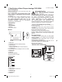
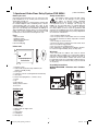
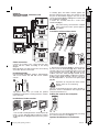
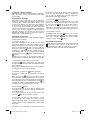
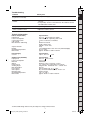
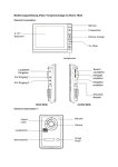
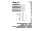
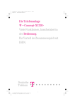
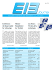
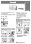
Typ: CVS
# 088344
MA_1fam_Video_88344_print.indd 1
06.06.14 11:09
1-Familienhaus Video-Türsprechanlage CVS 88344
Bevor Sie beginnen
Sicherheitshinweise
Stellen Sie sicher, dass Sie in Besitz aller Teile sind
(siehe Lieferumfang)
Diese 1-Familienhaus Video-Türsprechanlage wurde
dafür konzipiert um ankommende Besucher, die die
Klingel betätigen, zu identifizieren und Ihnen Einlass
zu gewähren.
Sie können diese Anlage selbstständig erweitern
(z. B. durch einen zweiten Monitor oder durch
eine weitere Außenstation. Bitte lesen Sie sich
die Bedienungsanleitung sorgsam durch, um eine
gelingende Installation und ein einwandfreies
Funktionieren zu gewährleisten.
Bei Schäden, die durch Nichtbeachtung
dieser Bedienungsanleitung verursacht
werden, erlischt der
Garantieanspruch! Für Folgeschäden übernehmen
wir keine Haftung! Bei Sach- oder Personenschäden,
die durch unsachgemäße Handhabung oder
Nichtbeachtung der Sicherheitshinweise verursacht
werden, übernehmen wir keine Haftung. In
solchen Fällen erlischt jeder Gewährleistungsund Garantieanspruch. Aus Sicherheits- und
Zulassungsgründen ist das eigenmächtige Umbauen
und/oder Verändern des Gerätes nicht gestattet.
Lieferumfang
1.Bauen Sie die Einheiten nicht auseinander.
2.Lassen Sie den Monitor nicht mit Wasser in
Berührung kommen.
3.Geräte nicht fallen lassen oder extremen Stößen
aussetzen.
4.Ziehen Sie den Netzstecker, falls Sie das Gerät für
längere Zeit nicht benutzen wollen.
5.Bedecken Sie nicht die Lüftungsschlitze.
6.Diese Geräte sind nicht für den Einsatz in sehr
feuchten, staubigen oder schmutzigen Umgebungen
gedacht.
1 Monitor
1 Außenstation
1 Wandhalterung
1 Netzteil
6 Schrauben/Dübel
Monitor
11
1
Sonstige Hinweise
1.Installieren Sie die Geräte nicht, wo diese direkt
extremer Helligkeit (z. B. direkter Sonnenstrahlung)
ausgesetzt sind.
2.Installieren Sie die Außenstation nicht, wo diese
direktem Regen ausgesetzt ist
3.Installieren Sie die Außenstation nicht dort, wo sie
Gefahr läuft, daß die Linse zerkratz wird.
10
2
3
(2- Draht- Technik)
4
5
9
6 7 8
1Bildschirm
2 Sprechtaste (Monitor Stand-By Mode)
3Türöffnertaste
4 Wechsel Kamera 1
Kamera 2 (bei optionalem zweitem Monitor)
5Toröffnertaste
6 Einstellungen/Menü (Helligkeit, Kontrast, Farbe)
7 Menü runter
8 Menü hoch
9Mikrofon
10Lautstärkeregelung
11Stromanschluss Netzteil
Standardverkabelung
1 Monitor und 1 Außeneinheit
DIP Setting
Außenstation
1
2
3
4
5
6
1Kameralinse
2 Weiße LEDs für Nachtsicht
3Lautprecher
4Namensschild
5 Klingelknopf
6Mikrofon
MA_1fam_Video_88344_print.indd 2
2
06.06.14 11:09
Schließen Sie die Stromversorgung erst
an, nachdem Sie die Außenstation mit der
Innenstation verkabelt haben!
D
GB
F
beschrieben und schließen Sie das Netzteil an die
vorgesehene Buchse an.
2.
Hängen Sie den Monitor sachte in die
Wandhalterung ein und halten Sie ihn bis zur
Endmontage fest (Abb. 2).
3. Sichern Sie den Monitor mit den beiden
mitgelieferten Schrauben von unten (Abb. 3).
NL
Optionale Verkabelung
2 Monitore und 2 Außeneinheiten
Montage der Außenstation
I
DIP Setting
S
E
MASTER
A
B
N
DIP Setting
Die Empfohlene Installationshöhe beträgt ca. 140 cm
für den Monitor und ca. 150 cm für die Außeneinheit.
Achten Sie darauf, dass die Kamera keiner
direkten Beleuchtung durch die Sonne oder
reflektierenden Oberflächen ausgesetzt ist.
140 cm
150 cm
70°
Tipp: Wir empfehlen die abgehenden Kabel durch
einen Kabelkanal zu führen, um Sie besser zu
schirmen und vor der Witterung zu schützen.
GR
SLO
Tipp: Stellen Sie vor fester Montage sicher, dass Sie
Ihre optimale Höhe gefunden haben und die max.
Entfernung zwischen Monitor und Außenstation nicht
überschreiten.
LV
Entfernen Sie die Frontplatte (Abb. B) in dem Sie
zunächst die beiden Schrauben auf der Unterseite
(Abb. A) lösen. 2. Befestigen Sie die Außenstation
an den dafür vorgesehen Stellen an die Wand mittels
Dübel und Schrauben (Abb. C). Schließen Sie
Außeneinheit an die vorverlegten Kabel an. An dieser
Stelle haben Sie die Möglichkeit, den Winkel des
Kameramodules geringfügig manuell zu justieren.
Richten Sie die Kamera in die gewünschte Position
3. Schrauben Sie die Frontplatte wieder fest
(Abb. D).
Installationshöhen
40°
D
LT
C
PL
Verbinden Sie den Monitor mit der Kamera und dem
Türöffner wie im Diagramm angegeben. Stecken Sie
die Kabel in die jeweiligen vorgesehenen Anschlüsse
in dem Sie die Stecker auf die vorgesehene Buchse
aufstecken, bzw. die Kabel anschließen. Achten Sie
unbedingt darauf, dass sich nach dem Anschluss
keine unisolierten Drähte berühren!
RO
Kabelverbindung
RUS
FIN
DK
SLAVE
CZ
SK
Montage der Monitors
3
1.Montieren Sie zuerst die Wandhalterung mit den
mitgelieferten 4 Dübeln und 4 Schrauben (Abb. 1).
Verdrahten Sie den Monitor wie im Diagramm
MA_1fam_Video_88344_print.indd 3
TR
2
3
H
1
06.06.14 11:09
Entfernen des Namensschildes
3. “Intercom”
(optional)
Sie können Gespräche zwischen zwei Innenstationen
führen.
Wenn Sie die “Intercom”
Taste drücken, klingeln
alle in das System eingebundenen Innenstationen.
Nehmen Sie den Ruf an, indem Sie die
Taste
betätigen. Sie beenden das Gespräch durch erneuten
Druck auf die Taste. Die Gesprächszeit beträgt hier
ebenfalls ca. 60 Sek. Danach wird as Gespräch
unterbrochen.
A
4.Türöffner
Taste
Falls Sie einen elektrischen Türöffner angeschlossen
haben, können Sie die Tür durch einfachen Druck auf
die
Taste öffnen und den Besucher hereinlassen.
Diese Funktion ist nur dann gegeben, wenn der
Monitor eingeschaltet ist. Nach Betätigen der
Türöffnerfunktion, schaltet sich der Monitor direkt
wieder in den Betriebsmodus.
Entfernen Sie die Abdeckung des Klingeltasters
in dem Sie die Abdeckung an den vorgesehen
Einkerbungen unten (Abb. A) lösen.
Optionale Installation eines
Hutschienentransformators
Alternativ können Sie das zugehörige Netzteil des
Monitors durch einen Hutschienentransformator
(Best.-Nr.: 8834402) ersetzen.
Wichtig: Der zu verwendende Türöffner muss
zwingend eine Memoryfunktion besitzen. Wir
empfehlen hierzu den GEV Türöffner mit der Best.Nr.: 007680 (11 cm) bzw. Best.-Nr.: 007697 (25 mm)
zu verwenden mit passendem Klingeltransformator
(Best.-Nr.: 007505B).
Anpassen der Bildschirmeinstellungen
Bei eingeschaltetem Monitor können Sie die Helligkeit,
den Kontrast und die Farbwiedergabe des Monitors
anpassen, in dem Sie den „Einstellungsknopf/
Bestätigung“ (6) betätigen.
Wenn Sie diesen Knopf drücken (siehe oben) erscheint
auf dem Monitor das Menü.
Sie können durch Betätigen der „hoch“/“runter“
Tasten (7,8) durch das Menü scrollen. Wählen Sie
das entsprechende Untermenü und bestätigen Sie
durch erneutes Drücken des Einstellungsknopfs
(6). Sobald Sie im Untermenü sind können Sie hier
ebenfalls durch scrollen der „hoch/ runter“ Knöpfe
(7,8) die für Sie passenden Einstellungen vornehmen.
Bestätigen Sie diese noch einmal durch Drücken des
„Bestätigungsknopfes“ (6).
5. Toröffner
Taste (optional)
Wenn Sie ein zusätzliches Tor oder eine zweite Tür
angeschlossen haben: Drücken Sie die
Taste auf
Ihrem Monitor. Diese Funktion ist nur dann gegeben,
wenn der Monitor eingeschaltet ist. Nach Betätigen
der Toröffnerfunktion schaltet sich der Monitor direkt
wieder in den Stand-By Modus.
6. Klingelmelodie ändern
Drücken Sie im Stand-By Modus die
Taste,
woraufhin die gegenwärtige eingestellt Melodie ertönt.
Drücken Sie
um einen anderen Klingelton zu
wählen. Insgesamt haben Sie vier Töne zur Auswahl.
Abschließend zum Bestätigen die
Taste drücken.
Bedienung
Wichtig: Die Sensortasten sachte mit den Fingern
berühren.
1. Nutzung der grundlegenden Funktionen der VideoTürsprechanlage
Wenn der Klingelknopf an der Außenstation gedrückt
wurde ertönt an der Innenstation ein Signal und der
Monitor schaltet sich automatisch ein. Wenn Sie den
Besucher identifiziert haben und Sie mit Ihm sprechen
möchten, berühren Sie die
Taste. Diese Funktion
bleibt für ca. 60 Sek. aktiv, danach schaltet sich der
Monitor automatisch aus. Um Ihn zu reaktivieren und
die Konversation weiterzuführen, berühren Sie die
Taste und danach wieder die
Taste.
Sollten Sie nicht auf ein eingehendes Signal reagieren,
schaltet sich der Monitor nach ca. 30 Sek. wieder in
den Stand-By-Modus.
Recycling-Hinweise
Dieses Gerät darf nicht mit dem unsortierten
Hausmüll entsorgt werden. Besitzer von
Altgeräten sind gesetzlich dazu verpflichtet,
dieses Gerät fachgerecht zu entsorgen. Informationen
erhalten Sie von Ihrer Stadt- bzw. Gemeindeverwaltung.
2.Aktivieren der Kamera ohne eingehendes Signal
a)Berühren Sie die
Taste am Monitor wann immer
Sie wollen und die Kamera schaltet sich für ca. 30
Sek. in den Betriebszustand
b)
Falls Sie eine optionale zweite Außeneinheit
installiert haben, können Sie durch Betätigung dieses
Knopfes
zwischen beiden hin und her schalten.
4
MA_1fam_Video_88344_print.indd 4
06.06.14 11:09
D
Häufige Fehlerursachen
Mögliche Ursache
Monitor ohne Funktion
• Strom richtig angeschlossen?
• Stecker eingesteckt?
Monitor zeigt Funktion,
aber kein Bild
• Ist das Kabel zwischen Kamera und Monitor korrekt
angeschlossen?
• Polarität der angeschlossenen Kabel zwischen Kamera und Monitor prüfen
Das Bild ist zu hell oder zu dunkel
• Helligkeit anpassen (siehe Anleitung)
Klingelsignal zu laut/leise
• Lautstärke anpassen
I
NL
F
GB
Problem
Technische und optische Änderungen ohne Ankündigung vorbehalten.
5
MA_1fam_Video_88344_print.indd 5
S
N
DK
FIN
RUS
GR
LV
H
TR
CZ
SK
SLO
RO
PL
Außeneinheit (8834403)
Spezifikationen
Eingangsspannung
DC 12 V (via Monitor)
Stromverbrauch
max. 3 W
GehäusematerialAluminium
Verdrahtungstechnik
Monitor: 2-Draht Türöffner : 2-Draht
Bildsensor
1/3“ Colour Sony Super HAD CCD Camera
Sichtwinkel
Diagonal: 90˚ Horizontal: 57,8˚ Vertikal: 48,6˚
Helligkeit
min. 0,5 Lux
Türöffner
Anschlusswert 12 V /max. 1,0 A
Toröffner
potentialfreier Kontakt Anschlusswert 40 V/1,5 A
MontageartAufputz
Betriebstemperatur
-10 ˚C bis +50 ˚C
Abmessungen
ca. B 95 x H 180 x T 20 mm
LT
NetzteilSpezifikationen
Spannungsversorgung
230 V ~, DC 17 V , 1,5 A
E
Technische Daten
Spezifikationen
Inneneinheit (8834401)
DC 17 V (Externes Netzteil)
Eingangsspannung Stromverbrauch
Standby: 2 W Betrieb : max. 14 W
Verbindungssystem
2 Draht; 2 Kameras, 2 Monitore
Klingeltöne4
Max. Entfernung/Kabeldurchmesser
min. Kabelquerschnitt zwischen Innen- und Außeneinheit
bis 50 Meter: ø 1,0 mm²
bis 100 Meter: ø 1,5 mm²
Display
173 mm TFT- LCD (LED Backlight)
Betriebstemperatur
0 ˚C bis +40 ˚C
Abmessungen
ca. B 200 x H 150 x T 20 mm
06.06.14 11:09
1 Apartment Video Door Entry System CVS 88344
(2-Wire installation)
Before you start
Safety Instructions
Parts
11
1.Do not disassemble the unit.
2. Do not spray water on the indoor unit. Do not keep
the outdoor unit where it will be exposed to extreme
moisture.
3. Do not drop or shock the unit.
4. Remove the power cord from the wall socket when
unit is not used for long periods.
5. Do not cover the ventilation holes.
6.This apparatus is designed for moderate climates.
Do not use in high humidity, dusty or dirty areas.
1
Warnings
Check the pack and make sure you have all of the
part listed below. If not, contact your local store who
will be able to help you.
This video door phone is composed of a monitor with
its modular adapter and a roadside panel. It allows
communicating with the visitor who calls at the
door and controlling the opening of the door and/or
gate. You can develop your installation by adding an
optional additional monitor and/or a second roadside
panel. For a safe installation and use, please read
carefully these instructions and keep them safe.
All warranty claims will be null and void in
the event of any damage or loss caused
by failure to observe these operating
instructions. We accept no liability for any
consequential losses or damage. We accept no
liability for any personal injury or material damage
caused by improper use or by failure to observe
the safety advice. In these cases the guarantee and
warranty are invalidated. For safety and authorization
purposes it is not permitted to carry out any adaptation
or conversion of the device
1 Indoor monitor
1 Outdoor station
1 Wall mounting bracket
1 Power adaptor
6 Screw/ Wall plug
Indoor unit
1.Do not install the outdoor unit where it will be
exposed to direct sunlight. Do not install the outdoor
unit where it will be subjected to extremes of dust or
moisture. Do not install the outdoor unit where it will
be exposed to rain. Do not install the outdoor unit in a
location where the lens filter is likely to get scratched
or very dusty.
10
2
3
4
5
9
6 7 8
Assembly instructions
WIRING DIAGRAM 1 Monitor and 1 Outdoor
Station
1 Monitor screen
2 Talk on/talk off (monitor off) and intercom (monitor standby mode)
3 Door open
4 Camera 1/camera 2 (with optional 2nd monitor)
5 Gate open
6 Menu select (brightness, contrast, color)
7Down
8Up
9Microphone
10Ring sound volume
11Power in
DIP Setting
Outdoor unit
1
2
3
4
5
6
1 Camera lens
2 White LEDs for night vision
3Speaker
4 Name plate
5 Call button
6Microphone
6
MA_1fam_Video_88344_print.indd 6
06.06.14 11:09
Only after having connected the roadside
panel, connect the 230 V~ power supply to
the adapter.
D
GB
F
2.Carefully place the indoor monitor against the
bracket and gently push down the monitor so that
the pins on the bracket engage in the slots on the
rear of the monitor (fig. 2). Hold tight the monitor until
the installation is finished.
3.Secure the assembly with the 2 screws from
underneath (fig. 3).
NL
Optional:
WIRING DIAGRAM 2 Monitors and
2 Outdoor stations
Installation of the outdoor device
I
DIP Setting
S
E
MASTER
B
N
A
DIP Setting
Recommended installation height is approximately
140 cm for monitor unit and 150 cm for outdoor
camera.
140 cm
150 cm
Important: do not point the video camera
directly at the sun or at reflecting
surfaces.
70°
Tip: we recommend passing the cables through a
protective sleeve to shield them from impacts and
environmental influences.
Tip: please make sure you found the optimal
installation height prior to having fixed the outdoor
unit to the wall.
GR
LV
1. Remove the front panel (fig. B). In the first loosen
the two screws on the bottom (fig. A). 2. Attach the
external station to the intended location on the wall
using wall plugs and screws (fig. C). Connect the
outdoor unit to the cables brought forward. At this
point, you have the possibility to adjust the camera’s
module angle slightly manually. Aim the camera in
the desired position. 3. Screw the front panel again
(fig. D).
Installation height
40°
D
LT
C
PL
Connect the monitor to the camera and the door
opener with the cables according to the wiring
diagram.
Make absolutely sure that no bare wires are touching
each other after the connection!
RO
Cable connection
RUS
FIN
DK
SLAVE
SLO
Adding the name to the nameplate
CZ
SK
Installation of indoor monitor
3
1.Fix the wall mounting bracket in the best place by
using 4 screws and plugs (fig. 1). Wire the monitor
as described in the diagram and connect the power
supply.
MA_1fam_Video_88344_print.indd 7
A
Remove the cover of the doorbell button by loosening
the notches below the cover (fig. A).
Optional installation of a transformer
7
TR
2
H
1
06.06.14 11:09
instead of a power adaptor
installed has a mechanical memory. We recommend
to use our GEV door openers order no. 007680 (11
cm) or order no. 007697 (25 mm) with appropiate
transformator Order No. 007505B.
Alternatively you may use a transformer to supply the
video door entry system with electricity (GEV order
no. 8834402).
Performance Settings
5. Activation of
button (optional)
If you have connected an additional gate or a second
door: If you want to open the gate to let the caller
in, just touch the
button on the indoor monitor.
This function can only be used when the screen is
switched on. It is normal that the image switches off
one moment following the control of the gate opener.
While the monitor is switched on you can adjust the
brightness, contrast and color of the monitor in which
you press the „settings/confirmation“ button. (6). If
you press this button (see above) the menu appears
on the monitor. By pressing the „up“/„down“ buttons
(7, 8) you can scroll through the menu. Select the
submenu and confirm by pressing the setting button
(6). Once you are in the submenu scroll through it by
using the „up/down“ (7, 8) buttons, too, to choose the
appropriate settings for you. Confirm this again by
pressing the „confirm button“ (6).
6. Changing the melody
At standby mode, touch the
button, you can hear
the melody. Then touch
to choose target melody.
There are 4 melodies available. To confirm melody
you have chosen, touch
button.
Operating Instructions
Important: the touch keys must be handled by slightly
touching with the fingers.
1. Activation of units
When the call button on the outside camera unit is
pressed, the indoor unit chime rings and the visitor’s
picture will appear on the indoor monitor. After the
visitor is visually identified, and you wish to talk with
the visitor, touch the
button. The unit will remain
activated for approximately 60 seconds before it
automatically shuts off. To re-activate for continued
conversation, touch the
button and then touch the
button.
Should you not react on an incoming signal, the
monitor will go in stand-by after approx. 30 seconds
Recycling instructions
This device may not be disposed of with unsorted
household waste. Owners of old devices are
required by law to dispose of this device correctly.
Contact your town council for further information.
2.Activation of outside unit from monitor unit.
a)Touch the
button of the indoor unit at any time
and the outdoor camera will be activated and show
the outside view.
b)If you has installed two cameras, touch this button
to change from camera one to another.
3.Activation of “Intercom”
button (optional)
An intercom calling can be started by any indoor
monitor.
When the intercom
button on one indoor monitor
is touched, this will ring all monitors in a system,you
can talk with the one calling monitor by touching the
intercom button on the second monitor, touch
for
shutting off. There is approximately 60 seconds of
time before the unit automatically shuts off.
4. Door opener
button
If an electrical lock or door strike is added to the
installation, connect it to the terminals at the back of
the roadside panel.
If you want to open the door to let the caller in, just
touch the
button on the indoor monitor.
This function can only be used when the screen
is switched on. After usage the monitor switches
back to operating mode. It is normal that the image
switches off one moment following the control of the
door open.
Important: it is essential that the electric latch or lock
MA_1fam_Video_88344_print.indd 8
8
06.06.14 11:09
D
Troubleshooting
Check point
No power
(no picture on monitor)
• Is the power supply connected correctly?
Power is on, but no picture on the
monitor
• Is the cable firmly connected between the monitor and the camera?
• Is the polarity of wires correct between the outdoor camera unit and indoor monitor unit?
The picture is too dark or white
• Adjust brightness control
Chime sound is too low
• Adjust the volume control
I
NL
F
GB
Problem
Technical and design features may be subject to change without notice.
9
MA_1fam_Video_88344_print.indd 9
S
N
DK
FIN
RUS
H
TR
CZ
SK
SLO
RO
PL
Outdoor Unit (8834403)
Specifications
Input power
DC 12 V from monitor
Power consumption
max. 3 W
MaterialAluminium
Wiring
Monitor: 2 wires Door lock: 2 wires
Image sensor
1/3“ Colour sony super HAD CCD camera
Viewing Angle
Diagonal: 90˚ horizontal: 57.8˚ vertical: 48.6˚
Min. illumination
0.5 Lux
Door opener power output max. 12 V /1.0 A
Gate opener
dry contact/installed load max. 40 V/ 1.5 A
Mounting type
Surface mount
Operating temperature
-10 ˚C to +50 ˚C
Dimensions
approx. W 95 x H 180 x D 20 mm
GR
Specifications
230 V~, DC 17 V , 1.5 A
LV
Power Supply
Current
LT
Specifications
DC 17 V (External power supply)
Idle mode: 2 W Operating: max 14 W
2 wires: 2 Cameras, 2 Monitors
4
Monitor to camera
50 M: 1.0 mm² wire
100 M: 1.5 mm² wire
Acryl
7 Inch Digital wide screen TFT LCD (LED Backlight)
0 ˚C to +40 ˚C
approx. W 200 x H 150 x D 20 mm
E
Technical information
Indoor unit (8834401)
Input power
Power consumption
Connecting system
Call sounds
Max. distance and wiring
Aspect material
Display
Operating temperature
Dimensions
06.06.14 11:09
10
MA_1fam_Video_88344_print.indd 10
06.06.14 11:09
11
MA_1fam_Video_88344_print.indd 11
06.06.14 11:09
06/2014 UW
Gutkes GmbH
Rehkamp 13
30853 Langenhagen
Germany
www.gev.de
[email protected]
Hotline: +49 (0)180/59 58 555
Max. 14 Ct./Min aus dem deutschen Festnetz.
Mobil max. 42 Ct./Min.
International calls may vary.
MA_1fam_Video_88344_print.indd 12
06.06.14 11:09