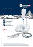
Download Vacuson 60 LP
Transcript
The Swiss Instruments
DE Bedienungsanleitung
EN Operation Manual
Vacuson 60 LP
31793 • V46/13 • NOUVAG AG©, all rights reserved
Suction Unit for Liposuction
Nouvag AG · St.Gallerstr. 23–25 · CH-9403 Goldach
Phone +41 (0)71 846 66 00 · Fax +41 (0)71 846 66 70
[email protected] · www.nouvag.com
DE: Technische Änderungen vorbehalten. Durch Weiterentwicklungen können Abbildungen und technische Daten geringfügig abweichen.
EN: Subject to change. Pictures and technical data may slightly differ due to consistent further development.
MD30
Vorwort
Herzlichen Glückwunsch zum Kauf eines Produktes der Firma NOUVAG AG. Wir freuen uns, dass Sie sich für ein
NOUVAG Erzeugnis entschieden haben und danken Ihnen für Ihr entgegengebrachtes Vertrauen.
Diese Bedienungsanleitung wird Sie mit dem Gerät und seinen Eigenschaften vertraut machen, damit eine möglichst
lange und problemlose Funktion gewährleistet werden kann.
Im Anhang finden Sie die Konformitätserklärung und unsere autorisierten Servicestellen.
DE
EN
FR
• Bitte lesen Sie diese Anleitung vor Inbetriebnahme aufmerksam durch!
IT
Foreword
Congratulations on your purchase of a NOUVAG AG product. Thank you for the confidence shown in our products.
Please consult the instruction manual for the use and maintenance of the device in order to ensure that it will
function properly and efficiently for many years.
You will find the conformity statement and list of authorized service representatives attached.
• Please read instructions carefully before operating!
Préface
Félicitations vous venez d’acheter un produit NOUVAG AG. Merci de la confiance que vous montrez en nos
produits.
Merci de consulter le mode d’emploi pour l’utilisation et l’entretien de cet appareil de manière à vous assurer qu’il
fonctionnera correctement et efficacement pendant de nombreuses années.
Vous trouverez ci-joint les déclarations de conformité et la liste des agents agréés pour l’entretien.
• Lire soigneusement les instructions avant utilisation!
Prefazione
Ci congratuliamo con Lei per l’acquisto di un prodotto NOUVAG AG e le auguriamo un susseguirsi di successi
professionali.
Questo manuale l’aiuterà a conoscere meglio l’apparecchiatura e le sue caratteristiche. Contiene indicazioni utili che
le assicureranno un funzionamento efficiente ed una lunga durata.
Qui allegato troverete la dichiarazione di conformità e la lista dei rivenditori autorizzati.
• Prego leggere attentamente le istruzioni per l’uso prima di mettere in funzionamento!
Preposición
Muchas gracias por la compra de un producto NOUVAG AG.
Felicidades por la elección y la confianza depositada en nuestros productos.
Para garantizar una función duradera y eficiente del aparato, por favor consultar el manual de instrucciones.
El Certificado de Conformidad y la lista de Centros de Servicio se encuentran en el apéndice.
• Por favor leer las instrucciones detenidamente antes de poner en marcha el aparato!
ES
Vacuson 60 LP
Inhaltsverzeichnis
DE
1
Produktbeschreibung
2
1.1
1.2
1.3
1.4
1.5
Einsatz und Funktionsweise
Kontraindikation
Technische Daten Vacuson 60 LP
Umgebungsbedingungen
Garantieleistungen
2
2
2
2
2
2
Erläuterung der Symbole
3
3
Sicherheitshinweise
3
3.1
3.2
3.3
3.4
EMV-Herstellererklärung
Manipulationen und Zweckentfremdung
Grundsätzliches
Bei der Anwendung
3
3
4
4
4
Lieferumfang
4
5
Geräteübersicht
5
6
Inbetriebnahme
6
6.1
6.2
6.3
6.4
6.5
Aufstellen des Gerätes
Anschluss an die Spannungsversorgung
Sekretflaschen vorbereiten
Conformkanülen-Handstück vorbereiten
Gerätevorbereitung
6
6
6
7
8
7
Bedienung
10
7.1
7.2
7.3
7.4
7.5
7.6
7.7
Gerät ein- bzw. ausschalten
Bedienung Vario-Pedal
Regulieren des Absaugvorgangs
Regulieren der Infiltrations-Leistung
Einsatz des Conformkanülen-Handstücks
Entleeren voller Sekretflaschen
Funktionskontrolle
10
10
10
10
11
11
11
8
Reinigung, Desinfektion und Sterilisation
12
8.1
8.2
8.3
8.4
8.5
8.6
8.7
8.8
Steuergerät und Vario-Pedal
Sekretflaschen und Sekretflaschen-Deckel
Bakterienfilter
Köcher
Silikonschläuche
Absaugkanülen
Conformkanülen-Handstück mit Handgriff
Elektronikmotor 31 ESS
12
12
12
12
13
13
14
15
9
Wartung
16
9.1
9.2
9.3
9.4
9.5
9.6
9.7
Austausch der Steuergerätesicherung
Sicherheitstechnische Kontrollen
Bakterienfilter
Sekretflasche
Funktionskontrolle der Überlaufsicherung
Zerlegen der Überlaufsicherung
Dichtungen und Schläuche
16
16
16
17
17
17
18
10
Störungen und Fehlerursachen
19
11
Ersatzteile und Zubehör
20
12
Hinweise zur Entsorgung
21
Bedienungsanleitung Vacuson 60 LP, Art.-Nr. 31793, V46/13
1
Vacuson 60 LP
1
Produktbeschreibung
1.1
Einsatz und Funktionsweise
Die VACUSON 60 LP ist eine sinnvoll und präzise aufeinander abgestimmte LiposuktionGerätekombination (Infiltrations- und Absaugpumpe) zur gewebeschonenden Liposuktion mit oder ohne
Tumeszenz-Lokalanästhesie.
In Verbindung mit dem entsprechenden Zubehör kann eine schonende Behandlung durchgeführt werden,
die wesentliche Vorteile für die ambulante Fettabsaugung beinhaltet. Bei richtiger Anwendung wird die
Fettabsaugung einfacher, komplikations- und risikoarm, sicherer und verringert die anfallenden Kosten und
führt zu optimalen kosmetischen Ergebnissen.
1.2
Kontraindikation
Relative oder absolute Kontraindikationen ergeben sich aus den generellen Erkenntnissen über den Patientenzustand sowie der Anästhesie.
1.3
Technische Daten Vacuson 60 LP
Betriebsspannung:
für 115 V -Modell, Art.-Nr. 4209-115:
für 230 V -Modell, Art.-Nr. 4209-230:
Leistungsaufnahme:
Sicherung:
für 115 V -Modell, Art.-Nr. 4209-115:
für 230 V -Modell, Art.-Nr. 4209-230:
Schutzklasse:
Anwendungsteil:
Regelbarer Unterdruck:
Masse, B x H x T:
Gewicht:
Genauigkeit Manometer:
Drehzahl Konform-Kanülen-Handstück:
Saugleistung Vakuumpumpe:
Motorleistung Vakuumpumpe:
1.4
2 x T4 AL 250 VAC
2 x T2 AL 250 VAC
Klasse I
Typ BF
-0,9 bar bei 686 mm HG
360 x 300 x 280 mm
14 kg
±5%
10’000 U/min = 3600 Hübe
60 l/min (bei wässrigen Lösungen, ohne Instrumente)
250 Watt
Umgebungsbedingungen
Relative Luftfeuchtigkeit:
Temperatur:
Luftdruck:
1.5
115 V~bei 60 Hz
230 V~bei 50 Hz
320 VA
Transport und Lagerung:
Max. 90 %
0°C bis 60°C
700 hPa bis 1060 hPa
Betrieb:
Max. 80 %
10°C bis 30°C
800 hPa bis 1060 hPa
Garantieleistungen
Mit dem Kauf des Vacuson 60 LP erhalten Sie Anspruch auf 1 Jahr Garantie. Wird die Garantiekarte innerhalb von vier Wochen ab Kaufdatum zur Registrierung zurückgesendet, erweitert sich die Garantieleistung
um weitere 6 Monate.
Verschleißteile sind von der Garantie ausgeschlossen. Unsachgemäßer Gebrauch und Reparatur, sowie die
Nichteinhaltung unserer Anweisungen entbindet uns von jeder Garantieleistung und anderen Ansprüchen.
2
Bedienungsanleitung Vacuson 60 LP, Art.-Nr. 31793, V46/13
Vacuson 60 LP
2
3
Erläuterung der Symbole
Hinweis beachten
Autoklavierbar bei 135°C
Warnung
Für Thermodesinfektion geeignet
Herstellungsdatum
Schutzerde
Hersteller
Gebrauchsanweisung beachten
Anwendungsteil des Typs BF ist der Saugschlauch mit dem angeschlossenen Instrument
Ausgediente Elektro- und Elektronikgeräte
sind Sondermüll und dürfen nicht mit dem
Hausmüll entsorgt werden. Es gelten die ortsüblichen Entsorgungsvorschriften.
Schutz gegen Berührung und dauerndes
Untertauchen
Symbol mit Hinweis auf Seriennummer mit
Herstelldatum Jahr/Monat
Pedal
Symbol mit Hinweis auf Bestellnummer
Haltbarkeitsdatum
Symbol mit Hinweis auf die Chargennummer
CE-Zeichen mit benannter Stelle
Nicht zur Wiederverwendung
DE
Sicherheitshinweise
Ihre Sicherheit, die Ihres Teams und selbstverständlich die Sicherheit Ihrer Patienten ist uns ein großes
Anliegen. Daher ist es unerlässlich, die folgenden Hinweise zu beachten:
3.1
EMV-Herstellererklärung
Zur elektromagnetischen Kompatibilität beachten Sie bitte die Hinweise, welche dieser Bedienungsanleitung beigefügt sind.
3.2
Manipulationen und Zweckentfremdung
•
•
Eine Änderung/Manipulation der Vacuson 60 LP-Pumpe und dessen Zubehör ist nicht erlaubt. Für
eventuelle Folgeschäden, die aus einer unerlaubten Änderung/Manipulation folgen, übernimmt der
Hersteller keinerlei Haftung. Die Garantie erlischt.
Eine Verwendung des Vacuson 60 LP außerhalb der in Kapitel 1.1 beschriebenen Indikationen ist nicht
erlaubt. Die Verantwortung dafür übernimmt allein der Anwender bzw. Bediener.
Bedienungsanleitung Vacuson 60 LP, Art.-Nr. 31793, V46/13
3
Vacuson 60 LP
3.3
Grundsätzliches
Die Vacuson 60 LP-Pumpe darf nur unter ständiger Aufsicht von fachkundigem und geschultem
Personal bedient werden!
Unsachgemäßer Gebrauch und Reparatur des
Gerätes, sowie die Nichteinhaltung unserer Anweisungen, entbindet uns von jeder Garantieleistung oder anderen Ansprüchen!
Die Verwendung von Fremdprodukten liegt in
der Verantwortung des Betreibers! Die Funktion
und Patientensicherheit kann mit fremdem
Zubehör nicht garantiert werden.
Vor dem Gebrauch, der Inbetriebnahme und
jeder Anwendung hat sich der Anwender vom
ordnungsgemäßen Zustand des Gerätes und
seines Zubehörs zu versichern. Dies beinhaltet
Sauberkeit, Sterilität und die Funktion.
Reparaturen dürfen nur durch autorisierte
NOUVAG-Service-Techniker vorgenommen
werden!
3.4
4
Bei der Anwendung
Das Gerät wird nicht steril ausgeliefert! Alle
sterilisierbaren Teile müssen vor dem Gebrauch
sterilisiert werden (siehe «8.0 Reinigung, Desinfektion und Sterilisation»).
Bei der Auswahl des Instrumentes hat der
Anwender darauf zu achten, dass dieses gemäß
EN ISO 10993 biokompatibel ist.
Das Steuergerät Vacuson 60 LP muss im Betrieb
im Operationssaal mindestens 1 m über dem
Boden sein.
Gerät nicht in der Umgebung von brennbaren
Gemischen verwenden.
Lieferumfang
Art.-Nr. Bezeichnung
Stückzahl
Vacuson 60 LP, 115 V-Modell, Art.-Nr. für komplettes Set 4179-115
4209
Steuergerät Vacuson 60 LP-----------------------------------------------------------------------------------------------1 Stück
4285
Vacuson 60 LP, 230 V-Modell, Art.-Nr. für komplettes Set 4179-230
Steuergerät Vacuson 60 LP-----------------------------------------------------------------------------------------------1 Stück
4122
1861nou
4052
4058
4246
4075
6026
28535
6022
2058nou
5103
5077nou
4043
1066
28857
1770
1958
1942
31793
Gemeinsame Ausstattungsmerkmale für 115 V und 230 V-Modell:
Stativ Vacuson ---------------------------------------------------------------------------------------------------------------1 Stück
Vario Fußschalter mit Pedal, IP68 --------------------------------------------------------------------------------------1 Stück
Sekretflasche, 2 Liter, Polypropylen ----------------------------------------------------------------------------------- 2 Stück
Sekretflaschen-Deckel für 2 und 5 Liter-Sekretflaschen---------------------------------------------------------- 2 Stück
Bakterienfilter, Ø 64 mm, PTFE, hydrophob------------------------------------------------------------------------ 10 Stück
Verbindungsschlauch zwischen Bakterienfilter und Sekretflsche, 8 x3 x 400 mm, sterilisierbar -------1 Stück
Einweg-Saugschlauch 8 x 5 x 4000 mm -------------------------------------------------------------------------------1 Stück
Übergangsstutzen abgewinkelt zu Sekretflaschen-Deckel und Saugschlauch-------------------------------1 Stück
Schlauchset zur Infiltration -----------------------------------------------------------------------------------------------1 Stück
Elektronik-Motor 31 ESS, bis 40’000 U/min --------------------------------------------------------------------------1 Stück
Handgriff zu Konformkanülen-Handstück----------------------------------------------------------------------------1 Stück
Konformkanülen-Handstück ---------------------------------------------------------------------------------------------1 Stück
Köcher, 30 cm, sterilisierbar zur Ablage des Konformkanülen-Handstücks ----------------------------------1 Stück
Handstück-Ablage, grau---------------------------------------------------------------------------------------------------1 Stück
Clips zur Befestigung des Saugschlauchs an Konformkanülen-Handstück und Motorkabel------------ 5 Stück
Flaschenhalter für Infiltrations-Flüssigkeit ---------------------------------------------------------------------------1 Stück
Aufsatz zu Nou-Clean Spray zur Pflege des Handstücks ----------------------------------------------------------1 Stück
Aufsatz zu Nou-Clean Spray zur Pflege des Elektronik-Motor 31 ESS ------------------------------------------1 Stück
Bedienungsanleitung Vacuson 60 LP auf CD-ROM ----------------------------------------------------------------1 Stück
Der Artikel 1984, Nou-Clean Spray kann aufgrund der Gefahrengutbestimmungen nicht mit dem
Steuergerät mitgeliefert werden und muss somit separat bestellt werden.
4
Bedienungsanleitung Vacuson 60 LP, Art.-Nr. 31793, V46/13
Vacuson 60 LP
5
Geräteübersicht
Frontansicht
18 17
1.
2.
3.
4.
5.
6.
7.
8.
9.
10.
11.
12.
13.
14.
15.
16.
17.
18.
19.
20.
21.
22.
23.
24.
25.
26.
27.
28.
29.
Konformkanülen-Handstück (optional)
Absaugkanüle (optional)
Köcher mit Halterung (optional)
Absaugschlauch
Stativ mit antistatischen, feststellbaren Rollen
Elektronischer Fußschalter mit Pedal
Schlauchset zur Infiltration
Infiltrationspumpe
Infiltrationsnadel
Flasche mit Infiltrationslösung
Flaschen-Halterung
Bakterienfilter
Verbindungsschlauch
Vakuum-Regler (VACUUM)
Bereitschaftsanzeige LED (POWER)
Manometer Vakuum mm/Hg
Regler für Infiltrationspumpe (INFILTRATION)
Sekretflaschendeckel
Anschluss Absaugschlauch
Sekretflasche
Buchse für Motoranschluss
Externer Erdungsanschluss (länderspezifisch)
Anschluss Fußschalter mit Pedal
Luft-Auslass (EXHAUST)
Anschluss für Vario-Pedal
Netzkabelanschluss
Hauptschalter Ein/Aus (O/I)
Fach mit Sicherungshalter
Typenschild mit Typenbezeichnung, ReferenzNummer, Seriennummer, Angaben zur Spannungsversorgung und der Angabe der GeräteSicherungen
30. Stativ-Halterung für Infiltrationslösung
16
DE
13
15
12
14
11
10
19
20
9
21
8
1
7
20
3
4
5
Geräte-Rückseite
11
10
22 24
30
8
6
29
23
25 26 27 28
Bedienungsanleitung Vacuson 60 LP, Art.-Nr. 31793, V46/13
5
Vacuson 60 LP
6
Inbetriebnahme
6.1
Aufstellen des Gerätes
• Die Vacuson 60 LP-Pumpe auf Stativ stellen und mit allen benötigten Erweiterungen und Instrumenten
bestücken. Rollen des Stativs arretieren. Stativ muss auf einem ebenen, rutschfesten Boden so aufgestellt
werden, dass alle Bedienelemente frei zugänglich sind.
• Der Aktionsradius des Gerätes samt Kabel und angeschlossenem Instrument darf nicht durch störende Einflüsse eingeschränkt werden.
• Die Sicht auf das Manometer muss allezeit gewährleistet sein.
• Der Fußschalter mit Pedal muss in Schrittweite zwischen Patient und Chirurg platziert werden.
• Es muss explizit darauf geachtet werden, dass keine Gegenstände auf das Pedal fallen können.
• Der Netzstecker, auf der Rückseite des Gerätes, muss jederzeit zugänglich sein.
• Die Lüftungsschlitze im Boden des Gehäuses des Vacuson 60 LP müssen frei gehalten werden, um übermäßigen Temperaturanstieg zu vermeiden.
• Das Gerät muss im Betrieb 1 Meter Abstand zum Boden aufweisen. Nouvag empfiehlt zur bequemen
Handhabung des Gerätes das mit Rollen versehene Stativ zu verwenden.
6.2
Anschluss an die Spannungsversorgung
Stellen Sie sicher, dass das Netzteil Ihres Gerätes mit der landestypischen Spannungsversorgung
übereinstimmt!
Das Netzteil für den Vacuson 60 LP lässt sich nicht umschalten, das Gerät muss gemäß der Spannungsversorgung des Landes, in der das Gerät betrieben wird, bestellt werden.
Um das Risiko eines elektrischen Schlages zu vermeiden, darf das Gerät nur an ein Versorgungsnetz mit
Schutzleiter angeschlossen werden.
Der Netzanschluss befindet sich auf der Rückseite des Gerätes.
6.3
1.
Sekretflaschen vorbereiten
Offene Sekretflasche (2 oder 5 Liter) bereithalten.
2.
Greifer des Sekretflaschendeckels unter den
Flaschenwulst einhängen und Deckel mit Kipphebel in Offen-Stellung auf die Flasche drücken.
Offen-Stellung
Dreh-Kipphebel in
Offen-Stellung.
Greifer
6
Bedienungsanleitung Vacuson 60 LP, Art.-Nr. 31793, V46/13
3.
4. Zur Sicherung Dreh-Kipphebel in die vorgesehene
Nut herunterklappen.
Dreh-Kipphebel am Sekretflaschendeckel um 180°
drehen (Dreh-Kipphebel zeigt jetzt vom Handgriff
des Deckels weg). Darauf achten dass der Riegel
unter den Wulst der Sekretflasche greift.
DE
Dreh-Kipphebel geschlossen
und gesichert.
Dreh-Kipphebel in
Geschlossen-Stellung.
Für weitere Informationen lesen Sie bitte die mit der Sekretflasche mitgelieferte Bedienungsanleitung,
Art.-No.: 31732.
6.4
Conformkanülen-Handstück vorbereiten
4
1
3
Klick
6
5
7
1
5
9
1. Schlauchadapter (6) gegebenenfalls vom Handstück (2) abschrauben.
2. Handstück (2) auf Motor (3) andrücken, bis Handstück einschnappt. Mit leichter Gegenbewegung Sitz des
Handstücks prüfen.
3. Motorenkabel (4) durch Klemmschraube (5) ziehen.
4. Handstück-Motor-Kombination bis zum Anschlag in den Handgriff (1) einführen.
5. Schlauchadapter (6) an Handstück anschrauben.
6. Silikonschlauch (7) mit Schlauchadapter und Schlauchanschluss des Handgriffs verbinden.
7. Klemmschraube (5) in Handgriff (1) eindrehen und festschrauben.
8. Absaugschlauch (8*) am vorgesehenen Anschluss am Handgriff aufpfropfen.
9. Absaugkanüle (9*) auf Adapter setzen und anschrauben.
(* Teile nicht im Lieferumfang enthalten!)
8
Vacuson 60 LP
6.5
Gerätevorbereitung
1. Alle zur Sterilisation vorgesehene Teile (z.B. Silikonschläuche, Kanüle, ConformkanülenHandstück, Absaugflasche und Deckel) müssen vor
dem Einsatz sterilisiert werden.
Zur Fixierung des Schlauchabschnittes die beiden
Schlauchklemmen rechts und links der Infiltrationspumpe einstellen. Pumpe verriegeln und mit
dem Daumen durch gleichzeitiges hinein- und herunterdrücken die Schlauchklemmen leicht an den
Schlauch drücken und loslassen. Die Schlauchklemmen sind dann arretiert und der Schlauchabschnitt ist in seiner Position fixiert.
2. Sekretflaschen mit aufgesetztem und verschlossenem Deckel in die Sekretflaschen-Halterung seitlich des Gerätes und vorne am Stativ einhängen.
5. Flasche mit Infiltrationslösung an das Stativ hängen und Einstechdorn des Schlauchsets durch die
Gummimembran der Flasche stecken. Entlüftungsventil am Einstechdorn öffnen.
3. Vario-Fußschalter mit Pedal auf den Boden legen
und den Stecker in die dafür vorgesehene Buchse,
hinten am Gerät, stecken.
4. Schlauchset zur Infiltration in die Infiltrationspumpe einhängen. Dazu Hebel der Pumpe in OffenStellung bewegen und Silikon-Abschnitt des
Schlauchsets in die Pumpe einlegen. Flussrichtung
beachten!
8
Infiltrationsnadel (optional) auf Schlauchset mit
Luer-Lock-Verbindung schrauben. Quetschrolle bis
zum Anschlag öffnen. Infiltrationsmenge wird
durch den Regler (INFILTRATION) gesteuert.
Bedienungsanleitung Vacuson 60 LP, Art.-Nr. 31793, V46/13
Vacuson 60 LP
6. Köcher zur Ablage des ConformkanülenHandstücks mit Kanüle vorne am Stativ einhängen.
7. Kurzes Silikon-Schlauchstück (40 cm lang) am
einen Ende mit der kleinen Verbindungshülse des
Flaschendeckels verbinden. Anderes Schlauchende
mit dem Bakterienfilter verbinden.
8. Das eine Ende des Absaugschlauchs (400 cm) mit
dem Übergansstutzen (Art.-Nr. 28535)
bestücken und das andere Ende mit dem Konformkanülen-Handstück verbinden.
9. Nun das Kurze Schlauchstück mit dem Bakterienfilter auf den Ansaugstutzen oben am Gerät aufpfropfen. Die Hülse am anderen Ende des
Schlauchstücks auf den kleinen Stutzen (VACUUM) des Deckels der Sekretflasche pfropfen.
10. Den Übergangsstutzen (Art.-Nr. 28535) des Absaugschlauches (400 cm) auf den großen Anschluss (PATIENT) des Sekretflaschen-Deckels
pfropfen. Das andere Ende des Schlauchstücks,
mit dem angeschlossenen Instrument, in den
Köcher hängen.
11. Netzstecker an die Stromversorgung anschließen.
Vergewissern Sie sich, dass die eingestellte Betriebsspannung und die landestypische Netzspannung
übereinstimmen!
Bedienungsanleitung Vacuson 60 LP, Art.-Nr. 31793, V46/13
9
DE
Vacuson 60 LP
7
7.1
Bedienung
Gerät ein- bzw. ausschalten
Mit dem Hauptschalter «I/O», auf der Rückseite des Gerätes, wird das Steuergerät einund ausgeschaltet. Auf der Frontseite des Gerätes wird die Bereitschaft mit einem grünen
LED-Licht (Power) angezeigt.
Das Ausschalten kann jederzeit erfolgen und ist nicht von einer Ausschaltprozedur
abhängig.
7.2
1
Bedienung Vario-Pedal
1. Fußbügel zum umplatzieren des Vario-Pedals.
2. Fußschalter «Vacuum» (blau) startet die Vakuumpumpe.
3. Fußschalter «Motor» (gelb) startet den Elektronikmotor zum
Antrieb des Kanülenhubs am Conformkanülen-Handstück.
4. Pedal um die Infiltrationspumpe in Gang zu setzten und die
Infiltrationsmenge bis zum eingestellten Maximalwert zu betreiben.
7.3
3
4
Regulieren des Absaugvorgangs
Der Absaugvorgang wird über den Vakuum-Regler «Vacuum» an der Frontseite des
Gerätes gesteuert.
Drehen im Uhrzeigersinn:
Drehen im Gegenuhrzeigersinn:
Vakuum wird stärker, Absaugleistung wird erhöht.
Vakuum wird schwächer, Absaugleistung reduziert.
Absaugsystem luftdicht machen und nach Lecks prüfen:
1. Vakuum-Regler an den linken Anschlag drehen (entspricht Vakuum-Minimum).
2. Gerät über Hauptschalter «I/O» einschalten und Fußschalter «Vacuum» am Vario-Pedal drücken. Pumpe läuft
und Vakuum wird aufgebaut.
3. Saugschlauch abklemmen, um maximale Dichte des Systems zu erzeugen.
4. Vakuum-Regler an den rechten Anschlag drehen (entspricht Vakuum-Maximum).
5. Warten bis die Pumpe maximales Vakuum aufgebaut hat (Maximal-Vakuum entspricht ≥ -0,9 bar).
6. Durch Drehen des Vakuum-Reglers kann jetzt die Absaugleistung von 0 bis -0,9 bar stufenlos eingestellt werden.
Die Pumpe läuft stets mit voller Leistung. Die Reduktion der Saugkraft wird beim Drehen des
Vakuum-Reglers im Gegenuhrzeigersinn durch Ansaugen von Fremdluft erreicht!
7.4
Regulieren der Infiltrations-Leistung
Mit dem Regler «Infiltration» wird die maximale per Pedal abrufbare Förderleistung der
Infiltrationspumpe eingestellt. Durch Drücken der Trittplatte des Vario-Pedals wird die
Infiltration gestartet, variiert und gestoppt.
Drehen im Uhrzeigersinn:
Drehen im Gegenuhrzeigersinn:
10
Infiltrationsmenge wird erhöht.
Infiltrationsmenge wird reduziert.
Bedienungsanleitung Vacuson 60 LP, Art.-Nr. 31793, V46/13
Vacuson 60 LP
7.5
Einsatz des Conformkanülen-Handstücks
Durch Drücken der Taste «Motor» am Vario-Pedal wird der Motor zur Hub-Bewegung
der Kanüle am Conformkanülen-Handstück aktiviert. Der Motor läuft mit konstanter
Geschwindigkeit von 10’000 U/min.
DE
Die Absaugung kann durch Drücken des Ventilknopfes am ConformkanülenHandstück unterbrochen werden.
Dadurch wird Fremdluft angesaugt, was zur Entleerung des Saugschlauches führt.
7.6
Entleeren voller Sekretflaschen
Der Sekretflaschendeckel ist mit einer Überlaufsicherung ausgestattet. Dies verhindert das Ansaugen von abgesaugter Sekretflüssigkeit bei zu hohem Füllgrad in der Sekretflasche. Dazu wird ein Schwimmer-System verwendet.
Bei zu hohem Flüssigkeitsniveau und daraus folgendem Schließen der Überlaufsicherung muss die Sekretflasche
entleert oder durch eine leere ersetzt werden.
1.
2.
3.
4.
5.
7.7
Absaugpumpe ausschalten.
Schläuche vom Sekretflaschen-Deckel entfernen.
Volle Flasche von Sekretflaschen-Halterung abhängen und abgesaugte Sekretflüssigkeit entsorgen.
Gebrauchte Sekretflasche dem Aufbereitungszyklus zuführen.
Abgehängte Schläuche mit bereitstehender zweiter Sekretflasche verbinden und Absaugprozedur fortsetzen.
Funktionskontrolle
Um einen problemlosen Betrieb der Absaugpumpe zu gewährleisten, müssen die einzelnen Komponenten und Funktionen vor jeder Behandlung geprüft werden.
Generelle Funktion:
1. Gerät über Hauptschalter «I/O» einschalten, Bereitschaftsanzeige (LED) leuchtet.
2. Weder die Infiltrationspumpe noch die Absaugpumpe und der Elektronikmotor des ConformkanülenHandstücks dürfen anlaufen ohne dass das Pedal bedient wird.
Absaugpumpe:
1. Fuß-Taste «Vacuum» (blaue Fußtaste) am Vario-Pedal drücken. Pumpe läuft.
2. Hand vor den Luftauslass «Exhaust» halten (Rückseite des Gerätes). Luftstrom ist fühlbar.
3. Vakuum-Regler (Vacuum) an den rechten Anschlag drehen, um die maximale Saugleistung abzurufen.
4. Saugintensität am Kanülen-Ende kontrollieren. Pumpe saugt stark.
5. Vakuum-Regler (Vacuum) an den linken Anschlag drehen, um die minimale Saugleistung abzurufen.
6. Saugintensität am Kanülen-Ende kontrollieren. Pumpe saugt schwach.
7. Gerät über Hauptschalter «I/O» ausschalten, Bereitschaftsanzeige (LED) erlischt.
Infiltrationspumpe:
1. Regler «Infiltration» an den rechten Anschlag drehen (maximale Förderleistung).
2. Trittplatte am Vario-Pedal drücken, Infiltrationspumpe startet.
3. Regler «Infiltration» gegen den linken Anschlag drehen, um die Förderleistung zu reduzieren.
4. Förderleistung sinkt, bis zum Stillstand. Es wird keine Infiltrationslösung mehr gefördert.
5. Wurde die maximale Förderleistung am Drehregler «Infiltration» eingestellt, kann die Förderleistung per Trittplatte am Vario-Pedal bis zum eingestellten Maximalwert reguliert werden.
Conformkanülen-Handstück mit Elektronikmotor:
Durch Drücken der Fußtaste «Motor» (gelbe Fußtaste) wird der Elektronikmotor im Conformkanülen-Handstück
aktiviert und läuft mit konstanter Geschwindigkeit. Vibration am Conformkanülen-Handstück ist fühlbar.
Störungen und Fehlerursachen:
Um Störungen auf den Grund zu gehen, schlagen Sie diese Bedienungsanleitung bitte in Kapitel 10 nach, «Störungen
und Fehlerursachen».
Bedienungsanleitung Vacuson 60 LP, Art.-Nr. 31793, V46/13
11
Vacuson 60 LP
8
Reinigung, Desinfektion und Sterilisation
Für die Pflege des Materials sind insbesondere folgende wichtige Punkte zu beachten:
● Reinigung, Desinfektion und Sterilisation nach jeder Behandlung durchführen!
● Material nach Möglichkeit in der Sterilisationsverpackung autoklavieren!
● Sterilisationsverpackungen dürfen nur bis zu 80 % gefüllt werden!
● Material bei 135°C, während mindestens 5 Minuten, autoklavieren!
● Falls sterilisiertes Material nicht sofort zum Einsatz kommt, muss die Sterilisationsverpackung mit dem
Sterilisationsdatum beschriftet werden!
● Die Nouvag AG empfiehlt die Beigabe eines Sterilindikators
8.1
Steuergerät und Vario-Pedal
Steuergerät und Pedal kommen mit dem Patienten nicht in Berührung.
Äußerliche Wischdesinfektion mit mikrobiologisch geprüften Flächendesinfektionsmitteln oder 70 %-igem
Isopropyl-Alkohol verwenden. Die Abdeckhaube des Gerätes ist entsprechend abgedichtet und abwaschbar.
8.2
Sekretflaschen und Sekretflaschen-Deckel
Die Aufbereitungshinweise für die Sekretflaschen entnehmen Sie bitte der mit den Sekretflaschen mitgelieferten
Bedienungsanleitung.
8.3
Bakterienfilter
Der Bakterienfilter, oben am Gerät, zwischen Sekretflasche und Gerätepumpe, ist ein Einwegartikel und kann nicht
gewaschen oder sterilisiert werden.
Es empfiehlt sich das periodische Auswechseln des Bakterienfilters nach 8 Stunden Einsatzdauer, jedoch zwingend
nachdem Schaum oder infektiöses Material angesaugt wurde.
Durch die hydrophobe Auslegung des Bakterienfilters schließt er bei Kontakt mit wässrigen Flüssigkeiten,
um die Pumpe zu schützen. Bei feuchtem Bakterienfilter wird daher ein Weiterführen des Absaugvorgangs
verunmöglicht. Der Bakterienfilter muss ausgewechselt werden!
8.4
Köcher
Köcher von Rückständen befreien und reinigen. Dazu sauberen, befeuchteten Lappen und/oder geeignete Bürste
mit Desinfektionsmittel zum Abwischen verwenden.
1. Achtung! Es ist wichtig ein Desinfektionsmittel zu verwenden, welches Polycarbonat kompatibel ist.
2. Köcher in Sterilgut-Einzelverpackung (siehe DIN 58953) verpacken.
3. Eingepackten Köcher bei 135°C während mindestens 5 Minuten* autoklavieren.
4. Bei Autoklaven ohne Nachvakuum muss Trocknungsphase erfolgen. Köcher im Beutel mindestens 1 Stunde bei
Raumtemperatur, mit Papierseite nach oben, trocknen lassen.
Falls sterilisierter Köcher nach erfolgter Sterilisation nicht sofort zum Einsatz kommt, muss er auf der
Verpackung mit Sterildatum beschriftet werden! Nouvag AG empfiehlt die Beigabe eines Sterilindikators.
* Die Temperaturhaltezeiten richten sich nach den ländergültigen Richtlinien und Normen.
12
Bedienungsanleitung Vacuson 60 LP, Art.-Nr. 31793, V46/13
Vacuson 60 LP
8.5
Silikonschlauch
Art.-Nr. 4075, Verbindungsschlauch 8 x 3 x 400 mm von Bakterienfilter zu Sekretflasche, Silikon, sterilisierbar
Einschränkung der Wiederaufbereitung
Häufiges Wiederaufbereiten hat nur geringe Auswirkungen auf die Silikonschläuche. Das Ende der
Produktlebensdauer wird normalerweise von Verschleiß und Beschädigung durch Gebrauch bestimmt.
ANWEISUNGEN
Am Gebrauchsort
Keine besonderen Vorbereitungen.
Aufbewahrung und
Transport
Keine besonderen Anforderungen. Lange Wartezeiten bis zur Aufbereitung wegen Antrocknungsgefahr vermeiden.
Reinigungsvorbereitung
Keine besonderen Anforderungen.
Automatische Reinigung Ausstattung: Reinigungs-/Desinfektionsgerät mit speziellem Beladungsträger, welcher den Anschluss
und Desinfektion
von Schläuchen an das Reinigungs-/Desinfektionsgerät und die Spülung von Kanälen gewährleistet.
Als Reinigungsmittel neutrale oder alkalische Reiniger verwenden.
1) Silikonschläuche in Beladungsträger bestücken.
2) Reinigungszyklus mit ausreichender Reinigung und Spülung einstellen. Letzten Spülgang mit
deionisiertem Wasser durchführen.
3) 10-minütigen Spüldurchlauf bei 93°C vornehmen, um eine thermische Desinfektion zu bewirken.
4) Kontrolle beim Herausnehmen der Silikonschläuche, ob sich noch sichtbarer Schmutz in den
Schläuchen befindet. Falls notwendig, Zyklus wiederholen oder manuell reinigen.
Manuelle Reinigung
Ausstattung: neutrales Reinigungsmittel, weiche Bürste, fließendes Wasser
Verfahren:
1) Oberflächenverschmutzung von Silikonschläuchen spülen und wegbürsten.
2) Silikonschlauch mit Reinigungsmittel unter fließendem Wasser gründlich durchspülen.
Manuelle Desinfektion
Für die manuelle Desinfektion Silikonschläuche in Desinfektionsmittellösung einlegen.
Trocknung
Die Silikonschläuche nach der Reinigung und Desinfektion ausreichend im Trockenschrank trocknen
lassen.
Kontrolle und Wartung
Sichtprüfung auf Beschädigung und Verschleiß durchführen.
Verpackung
Einzeln: Silikonschläuche in Sterilgut-Einzelverpackung verpacken.
Sets: Silikonschläuche in dafür vorgesehene Trays einsortieren oder auf Allzweck-Sterilisationstrays
legen.
Sterilisation
Im Vakuum-Autoklav bei 135°C während mindestens 5 Minuten* autoklavieren. Bei der Sterilisation
von mehreren Einheiten in einem Sterilisationszyklus darf die Maximalbeladung des Sterilisators nicht
überschritten werden. Bei Autoklaven ohne Nachvakuum muss Trocknungsphase erfolgen. Silikonschläuche im Beutel mindestens 1 Stunde bei Raumtemperatur, mit Papierseite nach oben, trocknen
lassen.
* Die Temperaturhaltezeiten richten sich nach den ländergültigen Richtlinien und Normen.
Lagerung
Keine besonderen Anforderungen. Falls sterilisierte Silikonschläuche nach erfolgter Sterilisation nicht
sofort zum Einsatz kommen, sollten sie auf der Verpackung mit Sterilindikator und Sterildatum beschriftet werden.
• Das mitgelieferte Schlauchset Art.-Nr. 6026, Länge 4 m, ist ein steril geliefertes Schlauchset.
Dieses Schlauchset ist für den Einmal-Gebrauch bestimmt und darf nicht sterilisiert werden!
• Kontaminierte Schlauchsets müssen fachgerecht entsorgt werden!
8.6
Absaugkanülen
Die optionalen Absaug-Kanülen kommen mit dem Patienten in Berührung und müssen entsprechend aufbereitet
und sterilisiert werden.
Die Aufbereitungs-Anweisungen entnehmen Sie bitte der mit den Kanülen mitgelieferten Bedienungsanleitung.
Bedienungsanleitung Vacuson 60 LP, Art.-Nr. 31793, V46/13
13
DE
Vacuson 60 LP
8.7
Conformkanülen-Handstück mit Handgriff
Einschränkung der
Wiederaufbereitung
Häufiges Wiederaufbereiten hat nur geringe Auswirkungen auf das Conformkanülen-Handstück. Das
Ende der Produktlebensdauer wird normalerweise von Verschleiß und Beschädigung durch Gebrauch
bestimmt. Für den Motor muss die entsprechende Aufbereitungsanweisung beigezogen werden!
ANWEISUNGEN
Am Gebrauchsort
Oberflächenverschmutzung mit einem Einmaltuch/Papiertuch entfernen.
Aufbewahrung und
Transport
Keine besonderen Anforderungen. Lange Wartezeiten bis zur Aufbereitung wegen Antrocknungs- und
Korrosionsgefahr vermeiden.
Reinigungsvorbereitung Handstück in umgekehrter Reihenfolge als bei Inbetriebnahme zerlegen, von Rückständen befreien
und reinigen. Dazu sauberen, befeuchteten Lappen mit Reinigungs- oder Desinfektionsmittel zum
Abwischen verwenden. Conformkanülen-Handstück nicht in Ultraschallbad legen.
Automatische Reinigung und Desinfektion
Ausstattung: Reinigungs-/Desinfektionsgerät mit speziellem Beladungsträger, welcher den Anschluss
von Handstücken an das Reinigungs-/Desinfektionsgerät und die Spülung von Kanälen gewährleistet.
Als Reinigungsmittel neutrale oder alkalische Reiniger in der empfohlenen Konzentration verwenden.
1)
2)
3)
4)
5)
Manuelle Reinigung
Conformkanülen-Handstück und Handgriff in Beladungsträger bestücken (Spülung der Kanäle
muss gewährleistet sein).
Kleinteile in feinmaschigen Korb bestücken.
Programm starten. Letzten Spülgang mit deionisiertem Wasser durchführen.
10-minütigen Spüldurchlauf (Desinfektion) bei 93°C vornehmen, um eine thermische Desinfektion
zu bewirken.
Kontrolle beim Herausnehmen des Handstücks und des Handgriffs, ob sich noch sichtbarer
Schmutz in Zwischenräumen und Rillen befindet. Falls notwendig, Zyklus wiederholen oder manuell reinigen.
Ausstattung: Neutrales oder alkalisches Reinigungsmittel, weiche Bürste, fliessendes Wasser
Verfahren:
1) Oberflächenverschmutzung von Conformkanülen-Handstück spülen und wegbürsten.
2) Reinigungsmittel mit Bürste auf alle Oberflächen und Zwischenräume auftragen.
3) Conformkanülen-Handstück unter fließendem Wasser gründlich abspülen.
Silikonschlauch und Handgriff sofort nach der Liposuktion in Instrumentenreinigungslösung mit
hoher Fett- und Eiweißlösekraft einlegen (z.B. Edisonite). Bestandteile mit Druck durchspülen (z.B.
Druckwasseranschluss oder Perfusionsspritze).
Manuelle Desinfektion
Für die manuelle Desinfektion Conformkanülen-Handstück in RKI*-geprüftes Desinfektionsmittel
einlegen. (Einwirkdauer gemäß Angaben des Desinfektionsmittels)
* Desinfektionsmittel-Liste des RKI (Robert Koch Institut) beiziehen.
Trocknung
Wenn kein Trocknungsprogramm im Reinigungs-/Desinfektionsgerät zur Verfügung steht, ist das
Conformkanülen-Handstück manuell oder im Trockenschrank zu trocknen.
Kontrolle und Wartung
Sichtprüfung auf Beschädigung, Korrosion und Verschleiß durchführen. ConformkanülenHandstück nach Reinigung und Desinfektion mit Nou-Clean Spray von der Kupplungsseite her
durchsprühen und mit befeuchtetem Lappen kurz abwischen (siehe Anleitung auf Spraydose).
Art. No. 1958
Verpackung
Einzeln: Conformkanülen-Handstück in Sterilgut-Einzelverpackung verpacken. Der Beutel muss gross
genug sein, damit die Versiegelung nicht unter Spannung steht.
Sets: Conformkanülen-Handstücke in dafür vorgesehene Trays einsortieren oder auf AllzweckSterilisationstrays legen.
Sterilisation
Im Vakuum-Autoklav bei max. 135°C während mindestens 5 Minuten* autoklavieren. Bei der Sterilisation von mehreren Instrumenten in einem Sterilisationszyklus darf die Maximalbeladung des Sterilisators nicht überschritten werden. Bei Autoklaven ohne Nachvakuum muss Trocknungsphase erfolgen.
Conformkanülen-Handstück im Beutel mindestens 1 Stunde bei Raumtemperatur, mit Papierseite
nach oben, trocknen lassen.
* Die Temperaturhaltezeiten richten sich nach den ländergültigen Richtlinien und Normen.
Lagerung
14
Keine besonderen Anforderungen. Falls sterilisiertes Conformkanülen-Handstück nach erfolgter
Sterilisation nicht sofort zum Einsatz kommt, sollte es auf der Verpackung mit Sterilindikator und
Sterildatum beschriftet werden.
Bedienungsanleitung Vacuson 60 LP, Art.-Nr. 31793, V46/13
Vacuson 60 LP
8.8
Elektronikmotor 31 ESS
Einschränkung der
Wiederaufbereitung
Häufiges Wiederaufbereiten hat nur geringe Auswirkungen auf die Elektronikmotoren. Das Ende der Produktlebensdauer wird normalerweise von Verschleiß und Beschädigung durch Gebrauch bestimmt. Der Elektronikmotor
31ESS ist für 250 Sterilisationszyklen ausgelegt.
ANWEISUNGEN
Am Gebrauchsort
Oberflächenverschmutzung mit einem Einmaltuch/Papiertuch entfernen.
Aufbewahrung und
Transport
Keine besonderen Anforderungen. Lange Wartezeiten bis zur Aufbereitung wegen Antrocknungs- und Korrosionsgefahr vermeiden.
Reinigungsvorbereitung
Anschmutzungen an Elektronikmotor mit Einmaltuch/Papiertuch entfernen. Motorkappe abschrauben und Kabel
entfernen.
Automatische Reinigung
und Desinfektion
Ausstattung: Reinigungs-/Desinfektionsgerät mit speziellem Beladungsträger, welcher den Anschluss von Motoren
an das Reinigungs-/Desinfektionsgerät und die Spülung von Kanälen gewährleistet. Den Motor von der Vorderseite
her anspülen. Als Reinigungsmittel nur neutrale Reiniger verwenden.
Elektronikmotor in Beladungsträger bestücken (Spülung der Kanäle muss gewährleistet sein). Motorkappe mit
Kabel und Handstückträger in Korb bestücken. Reinigungszyklus mit ausreichender Reinigung und Spülung einstellen. Für letzten Spüldurchlauf deionisiertes Wasser verwenden. 10-minütiger Spüldurchlauf bei 93°C, um eine
thermische Desinfektion zu bewirken.
Beim Herausnehmen des Elektronikmotors, der Motorkappe mit Kabel und des Handstückträgers kontrollieren, ob
sich noch sichtbarer Schmutz in Zwischenräumen und Rillen befindet. Falls notwendig, Zyklus wiederholen oder
manuell reinigen.
Manuelle Reinigung
Ausstattung: neutrales Reinigungsmittel, weiche Bürste, fließendes, demineralisiertes Wasser (< 38°C)
Verfahren:
Abspülen und wegbürsten von Oberflächenverschmutzungen an Elektronikmotor, Motorkappe mit Kabel und
Handstückträger. Reinigungsmittel mit Bürste auf alle Oberflächen und Zwischenräume auftragen.
Elektronikmotor, Motorkappe mit Kabel und Handstückträger gründlich unter fließendem Wasser abspülen.
Manuelle Desinfektion
Für die manuelle Desinfektion Elektronikmotor, Motorkappe mit darunter liegendem Stecker und Kabel und Handstückträger mit geprüften Desinfektionsmitteln (ohne Chloranteil) abwischen.
Trocknung
Wenn kein Trocknungsprogramm im Reinigungs-/Desinfektionsgerät zur Verfügung steht, ist der Elektronikmotor
manuell oder im Trockenschrank zu trocknen. Danach Handstückträger wieder auf Motor schrauben.
Kontrolle und Wartung
Sichtprüfung auf Beschädigung, Korrosion und Verschleiß durchführen. Sprayaufsatz (1942) in den Handstückträger
am Elektronikmotor stecken und Motor maximal 3 Sekunden durchsprühen. Mit befeuchtetem Lappen kurz abwischen (siehe Anleitung auf Spraydose). Nach dem Kabel mit Motorkappe wieder auf Elektronikmotor schrauben.
Art. No. 1942
Verpackung
Einzeln: Elektronikmotor in Sterilgut-Einzelverpackung verpacken. Der Beutel muss groß genug sein, damit die
Versiegelung nicht unter Spannung steht. Die Nouvag AG empfiehlt einen Sterilindikator beizulegen.
Sets: Elektronikmotoren in dafür vorgesehene Trays einsortieren oder auf Allzweck-Sterilisationstrays legen.
Sterilisation
Im Vakuum-Autoklav (Klasse B oder S gemäß EN 13060) bei 135°C während mindestens 5 Minuten* autoklavieren.
Bei der Sterilisation von mehreren Instrumenten in einem Sterilisationszyklus darf die Maximalbeladung des Sterilisators nicht überschritten werden. Bei Autoklaven ohne Nachvakuum muss eine Trocknungsphase erfolgen. Elektronikmotor im Beutel mindestens 1 Stunde bei Raumtemperatur, mit Papierseite nach oben, trocknen lassen.
*Die Temperaturhaltezeiten richten sich nach den landesüblichen Richtlinien und Normen, maximale Haltezeit 25
Min.
Lagerung
Falls sterilisierter Elektronikmotor nach erfolgter Sterilisation nicht sofort zum Einsatz kommt, muss er auf der
Verpackung mit dem Sterilisationsdatum beschriftet werden. Es ist empfehlenswert ein Sterilindikator beizulegen.
Die oben aufgeführten Anweisungen wurden von der NOUVAG AG für die Aufbereitung zu dessen Wiederverwendung als geeignet eingestuft. Dem Aufbereiter
obliegt die Verantwortung, dass die tatsächlich durchgeführte Aufbereitung mit verwendeter Ausstattung, Materialien und Personal in der Aufbereitungseinrichtung
die gewünschten Ergebnisse erzielt. Dafür sind normalerweise Validierung und Routineüberwachung des Verfahrens erforderlich. Ebenso sollte jede Abweichung von
den bereitgestellten Anweisungen durch den Aufbereiter sorgfältig auf ihre Wirksamkeit und möglichen nachteiligen Folgen ausgewertet werden.
Bedienungsanleitung Vacuson 60 LP, Art.-Nr. 31793, V46/13
15
DE
Vacuson 60 LP
9
9.1
Wartung
Austausch der Steuergerätesicherung
Defekte Steuergerätesicherungen können vom Anwender selbständig ausgewechselt werden. Sie befinden sich auf
der Rückseite des Gerätes im Sicherungsfach neben dem Hauptschalter:
•
•
•
•
•
Netzstecker ziehen.
Sicherungsfach mit Hilfe eines Schraubendrehers öffnen.
Defekte Sicherung T 2 AL 250 VAC auswechseln.
Sicherungshalterung wieder einschieben und Sicherungsfach schließen.
Netzstecker wieder einstecken.
2
1
1.
2.
3.
4.
9.2
3
4
Verschluss Sicherungsfach
Sicherungsfach
Sicherung 1
Sicherung 2
Sicherheitstechnische Kontrollen
Verschiedene Länder fordern in Verordnungen Sicherheitstechnische Kontrollen (STK) von Medizingeräten. Die
Sicherheitstechnische Kontrolle ist eine für Betreiber von Medizinprodukten vorgeschriebene periodische Sicherheitsprüfung. Das Ziel dieser Maßnahme ist das rechtzeitige Erkennen von Gerätemängeln und Risiken für Patienten, Anwender oder Dritte.
Für die Vacuson 60 LP-Pumpe gilt ein Kontrollintervall von 2 Jahren.
Die NOUVAG AG bietet Kunden die Sicherheitstechnische Kontrolle an. Die Anschriften finden Sie im Anhang der
Bedienungsanleitung unter «Servicestellen». Für weitere Auskünfte kontaktieren Sie bitte unseren technischen
Kundendienst.
Weitere, internationale Servicestellen sind auf der Nouvag Webseite aufgelistet:
www.nouvag.com > Service > Servicestellen
9.3
Bakterienfilter
Der Bakterienfilter wird als Einwegartikel periodisch ausgewechselt, spätestens jedoch nach 8 Stunden Betrieb, oder
sofort, wenn Schaum oder infektiöses Material angesaugt wurde. Die Artikelnummer entnehmen Sie bitte dem Kapitel 11, Ersatzteile und Zubehör.
16
Bedienungsanleitung Vacuson 60 LP, Art.-Nr. 31793, V46/13
Vacuson 60 LP
9.4
Sekretflasche
Das einströmende Sekret-/Luftgemisch verursacht Schaumbildung in der Sekretflasche. Es empfiehlt sich daher ein
Mittel zu verwenden, das die Schaumbildung unterbindet. Vor dem Gebrauch der Sekretflaschen das AntiSchaummittel nach Angabe des Herstellers in die saubere und trockene Flasche einfüllen. Verwenden Sie keine
Desinfektionslösung, da die meisten dieser Lösungen Schaumbildung fördern.
Achten Sie darauf, dass die Sekretflaschen in gutem Zustand sind. Prüfen Sie die Flaschen regelmäßig auf Bruchstellen, Risse und einen einwandfreien Flaschenrand. Dies ist wichtig, um eine absolute Dichtheit des Systems zu
gewährleisten, was wiederum für eine einwandfreie Funktion der Absaugpumpe notwendig ist.
9.5
Funktionskontrolle der Überlaufsicherung
Die einwandfreie Funktion der Überlaufsicherung muss von Zeit zu Zeit geprüft werden.
1. Sekretflaschendeckel ohne Flasche mittels Verbindungsschlauch
(8 x 3 x 400 mm) mit Steuergerät verbinden.
2. Vakuumregler «VACUUM» am Steuergerät durch drehen im Uhrzeigersinn
öffnen.
3. Vakuum per Fußschalter am Vario-Pedal einschalten.
4. Schwimmer der Überlaufsicherung an den Flaschendeckel drücken.
5. Vakuumregler zeigt steigenden Wert, bis zum maximal erreichbaren Vakuum.
(>-0,9 bar).
Wenn das Manometer kein maximales Vakuum anzeigt, muss die Überlaufsicherung zerlegt, gereinigt
und die Dichtungen ersetzt werden.
9.6
Zerlegen der Überlaufsicherung
1. Gewindestutzen der Überlaufsicherung vom Anschlussstutzen am Sekretflaschendeckel abschrauben.
2. Dichtung aus Anschlussstutzen entfernen.
3. Überlaufsicherung und Schwimmer reinigen.
4. Neue Dichtung in Anschlussstutzen einsetzen.
5. Gewindestutzen der Überlaufsicherung wieder auf
Anschlussstutzen schrauben.
Funktionskontrolle nach dem Zerlegen:
6. Deckel senkrecht halten.
7. Schwimmer mehrmals gegen den Flaschendeckel drücken.
8. Schwimmer muss selbständig in Normallage zurückfallen.
Fällt der Schwimmer nicht selbständig in die Ausgangsposition zurück, muss die Reinigung wiederholt,
oder der O-Ring richtig eingesetzt werden.
Bedienungsanleitung Vacuson 60 LP, Art.-Nr. 31793, V46/13
17
DE
Vacuson 60 LP
9.7
Dichtungen und Schläuche
Damit die Saugpumpe einwandfrei funktioniert, müssen sämtliche Schläuche und Dichtungen periodisch geprüft
werden und spätestens nach 250 Sterilisationen oder fünf Jahren Gebrauch ausgewechselt werden. Nur wenn sie
unbeschädigt sind, kann ein vollständiges Vakuum aufgebaut werden.
Defekte Dichtungen und Schläuche müssen ausgetauscht werden.
7
2
6
3
4
1
1.
2.
3.
4.
5.
6.
7.
18
5
Dichtung (O-Ring) am Anschlussstutzen für Bakterienfilter am Steuergerät ---------------- 2 Stück ----- Art.-Nr. 4063
Verbindungsschlauch zwischen Bakterienfilter und Anschluss am Deckel (VACUUM)---- 1 Stück -------Art.-Nr. 4075
Dichtung (O-Ring) am Anschlussstutzen schmal (ausdrehbar, VACUUM) am Deckel ----- 4 Stück ----- Art.-Nr. 4064
Dichtung (O-Ring) Überlaufsicherung------------------------------------------------------------------ 1 Stück ----- Art.-Nr. 28958
Haupt-Dichtung zwischen Flaschendeckel und Flasche ------------------------------------------- 1 Stück ----- Art.-Nr. 28957
Dichtung (O-Ring) Anschlussstutzen breit (ausdrehbar, PATIENT) am Deckel -------------- 4 Stück ----- Art.-Nr. 4063
Saugschlauch zwischen Anschlussstutzen (PATIENT) und Kanüle ------------------------------ 1 Stück ------ Art.-Nr. 6026
Bedienungsanleitung Vacuson 60 LP, Art.-Nr. 31793, V46/13
Vacuson 60 LP
10
Störungen und Fehlerursachen
Störung
Gerät funktioniert nicht
Pedal funktioniert nicht
Absaugpumpe
funktioniert nicht
Ursache
Behebung
Hinweis Bedienungsanleitung
Steuergerät nicht eingeschal- Hauptschalter «I/O» auf «I»- 7.1 Gerät ein-, bzw. ausschalten
tet
Position schalten
Netzverbindung nicht herge- Steuergerät an Stromnetz
stellt
anschließen
6.4 Gerätevorbereitung
Falsche Betriebsspannung
Netzspannung überprüfen
6.2 Anschluss an die Spannungsversorgung
Defekte Sicherung
Austausch der Sicherung
9.1 Austausch der Steuergerätesicherung
Vario-Pedal nicht angeschlos- Vario-Pedal auf Rückseite des 6.4 Gerätevorbereitung
sen
Geräts anschließen
Steuergerät ist nicht eingeschaltet
Hauptschalter «I/O» auf «I»- 7.1 Gerät ein-, bzw. ausschalten
Position schalten
Fehlbedienung
Bedienungsanleitung gründlich lesen
Vakuumpumpe nicht eingeschaltet
Angeschlossenes Vario-Pedal 7.2 Pumpe aktivieren mit On/Offdrücken
Pedal
Undichtheiten
Sämtliche Dichtungen und
Schläuche prüfen. Sitz des
Flaschendeckels auf der Flasche kontrollieren
6.3 Sekretflasche vorbereiten
6.4 Gerätevorbereitung
9.7 Dichtungen und Schläuche
Anschlusskappe für den Luft- Kappe auf Pedalanschluss
einlass (Pedalanschluss) ist
setzen
nicht aufgesetzt.
6.4 Gerätevorbereitung
Falsch montierte Schläuche
6.4 Gerätevorbereitung
Schläuche richtig montieren
Flasche ist voll und die Über- Volle Flasche gegen eine leere 7.5 Entleeren voller Sekretflaschen
laufsicherung hat geschlossen austauschen
Fehlbedienung
Absaugpumpe saugt nicht Vakuum-Regler nicht genug
geöffnet
richtig
Undichtheiten
Bedienungsanleitung gründlich lesen
Regler «VACUUM» im
Uhrzeigersinn drehen
7.4 Regulierung des Absaugvorgangs
Sämtliche Dichtungen und
Schläuche prüfen. Sitz des
Flaschendeckels auf der Flasche kontrollieren
6.3 Sekretflasche vorbereiten
6.4 Gerätevorbereitung
9.7 Dichtungen und Schläuche
Kann ein Fehler nicht behoben werden, wenden Sie sich bitte an den Lieferanten oder an eine autorisierte Servicestelle.
Die Anschriften sind auf der letzten Seite der Bedienungsanleitung zu finden.
Bedienungsanleitung Vacuson 60 LP, Art.-Nr. 31793, V46/13
19
DE
Vacuson 60 LP
11
Ersatzteile und Zubehör
Dichtungselemente
(Siehe 9.7 Dichtungen und Schläuche)
Art.-Nr.
Steckhülsenelemente
Art.-Nr.
Steckhülse groß (PATIENT) am Sekretflaschendeckel zur Montage des Absaugschlauches------------------------------ 4056
Steckhülse klein (VACUUM) am Sekretflaschendeckel zur Montage des Verbindungsschlauches --------------------- 4047
Übergangsstutzen komplett für Sekretflaschendeckel-----------------------------------------------------------------------------28535
Schlauchelemente
Art.-Nr.
Verbindungsschlauch, Silikon, Bakterienfilter zu Flaschendeckel, (Aussen-Ø x Innen-Ø x Länge) 8 x 3 x 400 mm 4075
Saugschlauch, Silikon, autoklavierbar, Dimensionen (Aussen-Ø x Innen-Ø x Länge) 8 x 3 x 1700 mm ---------------- 4076
Saugschlauch, Einweg, steril, Länge 4 m----------------------------------------------------------------------------------------------- 6026
Zubehör
Art.-Nr.
Sekretflasche, Polypropylen, unzerbrechlich, autoklavierbar, 2 Liter Volumen --------------------------------------------- 4052
Sekretflasche, Polypropylen, unzerbrechlich, autoklavierbar, 5 Liter Volumen ---------------------------------------------- 4245
MONOKIT, Einweg Absaugflaschen-System, 2 Liter Volumen, mit Aufhängevorrichtung, komplett ------------------ 4038
MONOKIT, 2 Liter Einweg-Beutel inkl. Deckel, zu 50 Stück pro Verpackungseinheit ---------------------------------------4035
Bakterienfilter für Absaugpumpe, Einweg, hydrophob, Ø 64 mm, PTFE------------------------------------------------------- 4246
Flaschendeckel mit Überlaufsicherung zu 2- und 5 Liter-Sekretflaschen, komplett ---------------------------------------- 4058
Köcher, sterilisierbar, 30 cm Länge, mit Aufhängevorrichtung------------------------------------------------------------------- 4043
Köcher, sterilisierbar, 40 cm Länge, mit Aufhängevorrichtung ------------------------------------------------------------------4044
Yankauer Absaug-Kanüle, Länge 28 cm, Ø 2,0 mm --------------------------------------------------------------------------------- 4446
Andrews-Kanüle, Länge 24 cm, Ø 2,0 mm--------------------------------------------------------------------------------------------- 4449
Geburts-Saugglocke mit 60 mm Glockendurchmesser -----------------------------------------------------------------------------4053
Geburts-Saugglocke mit 70 mm Glockendurchmesser ---------------------------------------------------------------------------- 4054
Schlauchhalter zur Montage an Sanicar oder Stativ --------------------------------------------------------------------------------- 4118
Absaug-Kanülen für die Liposuktion
Art.-Nr.
Kanülen-Handgriff, mit Öffnung für Fremdluftzufuhr, Luer-Lock-Verbindung ----------------------------------------------- 4391
Kanülen-Handgriff ohne Öffnung, Luer-Lock-Verbindung ------------------------------------------------------------------------ 4390
Gebogene Kanülen für die Oberschenkel-Liposuktion, Ø 3 mm, Länge 200 mm, 22 Öffnungen 1,5 mm -------------- 4362
Gebogene Kanülen für die Oberschenkel-Liposuktion, Ø 3 mm, Länge 300 mm, 30 Öffnungen 1,5 mm ---------------4365
Gebogene Kanülen für die Oberschenkel-Liposuktion, Ø 4 mm, Länge 200 mm, 22 Öffnungen 1,5 mm-------------- 4368
Gebogene Kanülen für die Oberschenkel-Liposuktion, Ø 4 mm, Länge 300 mm, 30 Öffnungen 1,5 mm---------------4372
Gewinkelte Kanülen, 30°, für die Oberschenkel-Liposuktion, Ø 3 mm, Länge 200 mm, 22 Öffnungen 1,5 mm ------- 4381
Gerade Kanüle, Ø 1,5 mm, Länge 150 mm, 1 Öffnung oval -------------------------------------------------------------------------- 4361
Gerade Kanülen, Ø 2 mm, Länge 150 mm, 1 Öffnung oval ------------------------------------------------------------------------- 4364
Gerade Kanüle, Ø 2 mm, Länge 150 mm, 18 Öffnungen 1 mm ---------------------------------------------------------------------4373
Gerade Kanülen, Ø 3 mm, Länge 150 mm, 18 Öffnungen 1,5 mm----------------------------------------------------------------- 4374
Gerade Kanülen, Ø 3 mm, Länge 200 mm, 22 Öffnungen 1,5 mm --------------------------------------------------------------- 4378
Gerade Kanülen, Ø 3 mm, Länge 300 mm, 30 Öffnungen 1,5 mm --------------------------------------------------------------- 4387
Gerade Kanülen, Ø 4 mm, Länge 200 mm, 22 Öffnungen 2,0 mm -------------------------------------------------------------- 4379
Gerade Kanülen, Ø 4 mm, Länge 300 mm, 30 Öffnungen 1,5 mm --------------------------------------------------------------- 4388
Infiltrations-Kanüle
Art.-Nr.
Gerade Kanüle, Ø 3 mm, Länge 250 mm ----------------------------------------------------------------------------------------------- 4350
Zur Bestellung weiterer Teile steht Ihnen unser Kundendienst gerne zur Verfügung.
20
Bedienungsanleitung Vacuson 60 LP, Art.-Nr. 31793, V46/13
Vacuson 60 LP
12 Hinweise zur Entsorgung
Bei der Entsorgung von Gerät, Gerätbestandteilen und Zubehör müssen die lokalen, landesüblichen Vorschriften des
Gesetzgebers beachtet werden.
Steuergeräte nicht mit dem Hausmüll entsorgen!
Im Sinne des Umweltschutzes können Altgeräte an den Händler oder den Hersteller zurückgegeben werden.
Motoren, die Ihren Lebenszyklus vollendet haben, nicht mit dem Hausmüll entsorgen.
Vor der Entsorgung sind die Motoren zu sterilisieren. Bitte beachten Sie die lokalen, landesüblichen
Vorschriften für die Entsorgung von infektiösem Müll.
Kontaminierte Einweg-Schlauchsets müssen speziell entsorgt werden. Bitte beachten Sie die lokalen,
landesüblichen Vorschriften für die Entsorgung von infektiösem Müll.
Bedienungsanleitung Vacuson 60 LP, Art.-Nr. 31793, V46/13
21
DE
Vacuson 60 LP
Table of contents
1
Product description
2
1.1
1.2
1.3
1.4
1.5
Intended use and operation
Contraindications
Technical data, Vacuson 60 LP
Ambient conditions
Warranty coverage
2
2
2
2
2
2
Explanation of symbols
3
3
Safety information
3
3.1
3.2
3.3
3.4
EMC Manufacturer’s Declaration of Conformity
Modification and misuse
Essential requirements
During use
3
3
4
4
4
Scope of delivery
4
5
Device overview
5
6
Startup
6
6.1
6.2
6.3
6.4
6.5
Device setup
Connection to the power supply
Preparation of secretion jars
Preparing Conform Cannula Handpiece
Device preparation
6
6
6
7
8
7
Operation
10
7.1
7.2
7.3
7.4
7.5
7.6
7.7
Switching device on and off
Operation of the Vario footswitch with pedal
Regulation of suction performance
Regulation of infiltration performance
Operation of Conform Cannula Handpiece
Emptying secretion jar
Function control
10
10
10
10
11
11
11
8
Cleaning, disinfection and sterilization
12
8.1
8.2
8.3
8.4
8.5
8.6
8.7
8.8
Control unit and Vario Pedal
Secretion jar and jar lid
Bacteria filter
Quiver
Silicone tube
Cannulas
Conform Cannula Handpiece with Grasp
Electronicmotor 31 ESS
12
12
12
12
13
13
14
15
9
Maintenance
16
9.1
9.2
9.3
9.4
9.5
9.6
9.7
Replacing the control unit fuse
Safety inspections
Bacteria filter
Secretion jar
Function control of float gauge valve
Disassembly of the Overflow Protection System
Seals and tubes
16
16
16
17
17
17
18
10
Malfunction and troubleshooting
19
11
Accessories and spare parts
20
12
Information on disposal
21
Operating Instructions, Vacuson 60 LP, Art. No. 31793, V46/13
EN
1
Vacuson 60 LP
1
1.1
Product description
Intended use and operation
The VACUSON 60LP is a sensible and precisely integrated Liposuction device, combining infiltration and suction for
protective tissue treatment with or without local – anesthetic tumescence.
In combination with the corresponding accessories, safe, conservative treatment is assured, providing a crucial advantage in ambulatory Liposuction treatment. With proper application, the tissue removal procedure is simple, safe,
cost-effective and delivers optimal cosmetic results.
1.2
Contraindications
Relative or absolute contraindications may result from the general patient status or the risks of anesthesia
related to the treatment.
1.3
Technical data, Vacuson 60 LP
Voltage:
for 115 V model, Art. No. 4209-115:
for 230 V model, Art. No. 4209-230:
Power consumption:
Fuses:
for 115 V model, Art. No. 4209-115:
for 230 V model, Art. No. 4209-230:
Protection class:
Applied part:
Adjustable vacuum:
Dimensions, W x H x D:
Weight:
Accuracy limit, Manometer:
Speed of Conformcannula handpiece:
Suction Pump Capacity:
Pump motor power:
1.4
2 x T4 AL 250 VAC
2 x T2 AL 250 VAC
Class I
Type BF
-0,9 bar at 686 mmHG
360 x 300 x 280 mm
14 kg
±5%
10,000 rpm = 3600 strokes
60 l/min (for watery solutions, without attached instrument)
250 Watt
Ambient conditions
Relative humidity:
Temperature:
Atmospheric pressure:
1.5
115 V~at 60 Hz
230 V~at 50 Hz
320 VA
Transport and storage:
Max. 90 %
0°C to 60°C
700 hPa to 1060 hPa
Operation:
Max. 80 %
10°C to 30°C
800 hPa to 1060 hPa
Warranty coverage
Purchasing the Vacuson 60 LP Liposuction system entitles you to a 1-year warranty. If you return
the warranty card for registration within four weeks of the date of purchase, warranty coverage will be
extended for a further 6 month.
Consumable parts are not covered by the warranty. Improper use or repair, or failure to observe these
instructions, relieve us from any obligations arising from warranty provisions or other claims.
2
Operating instructions Vacuson 60 LP, Art. No. 31793, V46/13
Vacuson 60 LP
2
3
Explanation of symbols
Important information
Autoclavable at 135°C
Warning
Suitable for thermal disinfection
Date of manufacturing
Protective ground
Manufacturer
Observe the instructions for use
Type BF applied part is the filling tube
with connected instruments
Electrical and electronic devices that have
reached the end of their service life comprise
hazardous waste and may not be disposed of
together with household waste. Valid local
disposal regulations apply.
Protection against contact and continual
submerging.
Symbol indicating the serial number with the
date of manufacture (year/month).
Pedal
Symbol indicating the order number.
Date of expiry
Symbol indicating the lot number.
CE symbol with notified body
Not for reuse
EN
Safety information
Your safety, the safety of your team, and of course that of your patients is very important to us.
It is therefore essential to bear the following information in mind:
3.1
EMC Manufacturer’s Declaration of Conformity
Please observe the information on electromagnetic compatibility provided with these operating instructions.
3.2
Modification and misuse
•
•
Modification or manipulation on the Vacuson 60 LP liposuction pump system and its accessories is
prohibited. The manufacturer is not liable for any damages resulting from unauthorized modifications
or manipulations. The warranty will be canceled.
Use of the Vacuson 60 LP suction pump outside the indications described in Section 1.1 is prohibited.
The user or operator is solely responsible for any such use.
Operating Instructions, Vacuson 60 LP, Art. No. 31793, V46/13
3
Vacuson 60 LP
3.3
Essential requirements
The Vacuson 60 LP suction pump may only be
operated under constant supervision of qualified
and trained personnel!
Improper use or repair of the device and failure
to observe these instructions relieve us from any
obligation arising from warranty provisions or
other claims!
The use of third-party products is the responsibility of the operator. Functionality and patient
safety cannot be guaranteed with third-party
accessories.
Prior to using the device, before startup, and
before operation, the user must always ensure
that the device and accessories are in good working order and are clean, sterile and operational.
Repairs may only be performed by authorized
NOUVAG service technicians.
3.4
During use
The device is not sterile on delivery. All sterilizable parts must be sterilized before use (refer to
chapter 8 Cleaning, disinfection and sterilization).
At the choosing of the instrument the operator
has to make sure it’s biocompatible, according to
EN ISO 10993.
While in operation the control unit of the Vacuson 60 LP suction pump must be at least 1 meter
above ground.
Do not use the device in the vicinity of flammable mixtures.
4
Scope of delivery
Art. No.
4209
Description
Quantity
Vacuson 60 LP, 115 V modell, Art. No. for complete set 4179-115
Control unit Vacuson 60 LP ------------------------------------------------------------------------------------------------ 1 unit
4285
Vacuson 60 LP, 230 V modell, Art. No. for complete set 4179-230
Control unit Vacuson 60 LP ------------------------------------------------------------------------------------------------1 unit
4122
1861nou
4052
4058
4246
4075
6026
28535
6022
2058nou
5103
5077nou
4043
1066
28857
1770
1958
1942
31793
Common equipment features for 115 V and 230 V modell:
Stand for Vacuson ------------------------------------------------------------------------------------------------------------1 unit
Vario foot switch with pedal, IP68 ---------------------------------------------------------------------------------------1 unit
Secretion jar, 2 liter, polypropylene, sterilizable -------------------------------------------------------------------- 2 units
Jar lid for 2 and 5 liter secretion jars, sterilizable -------------------------------------------------------------------- 2 units
Disposable bacteria filter, Ø 64 mm, PTFE, hydrophobic --------------------------------------------------------10 units
Connecting tube, Silicone, bacteria filter to jar lid, 8 x 3 x 400 mm, sterilizable ------------------------------1 unit
Disposable suction tube 8 x 5 x 4000 mm ------------------------------------------------------------------------------1 unit
Angeled connector for secretion jar and suction tube, sterilizable ----------------------------------------------1 unit
Disposable tube set for infiltration --------------------------------------------------------------------------------------1 unit
Electronic motor 31 ESS, up to 40,000 rpm, sterilizable-------------------------------------------------------------1 unit
Handle for conform cannula handpiece, sterilizable -----------------------------------------------------------------1 unit
Conform cannula handpiece, sterilizable -------------------------------------------------------------------------------1 unit
Quiver, 30 cm, sterilizable, for repository of the conform cannula handpiece --------------------------------1 unit
Handpiece cradle, gray, sterilizable --------------------------------------------------------------------------------------1 unit
Clips to attach suction tube to motor cable of the conform cannula handpiece---------------------------- 5 units
Bottle holder for Infiltration liquid ---------------------------------------------------------------------------------------1 unit
Spray nozzle for Nou-Clean Spray for maintenance and care of handpieces ----------------------------------1 unit
Spray nozzle for Nou-Clean Spray for maintenance and care of electronic motor 31 ESS ------------------1 unit
Operating instructions for Vacuson 60 LP on CD-ROM ------------------------------------------------------------1 unit
In line with regulations pertaining to hazardous materials, the aricle 1984, Nou-Clean Spray is not
delivered with the control unit but can be ordered separately from any official Nouvag service center.
4
Operating instructions Vacuson 60 LP, Art. No. 31793, V46/13
Vacuson 60 LP
5
Device overview
13
15
Front view
18 17
1.
2.
3.
4.
5.
6.
7.
8.
9.
10.
11.
12.
13.
14.
15.
16.
17.
18.
19.
20.
21.
22.
23.
24.
25.
26.
27.
28.
29.
Conform cannula handpiece
Suction cannula
Quiver
Suction tube
Stand with antistatic rolls with brakes
Electronic foot switch with pedal
Infiltration tube set
19
Infiltration pump
Infiltration needle
Bottle with infiltration solution
Bottle holder
Bacteria filter
21
Connecting tube
Vacuum control (VACUUM)
Indicator light, LED (POWER)
1
Vacuum manometer, mm/Hg
Infiltration control (INFILTRATION)
Secretion jar lid
Suction tube connection
Secretion bottle
Motor socket
External grounding (country specific)
Connection for foot switch with pedal
AIR-Exhaust (EXHAUST)
Anschluss für Vario AIR pedal (optional)
Mains connection
3
Power switch ON/OFF (O/I)
Fuse compartment
Type plate with device name, reference number, serial number, voltage information, fuse
information
4
30. Stand holder for infiltration bottle
16
12
14
11
EN
10
20
9
8
7
20
5
Rear view
11
10
22 24
30
8
6
29
23
25 26 27 28
Operating Instructions, Vacuson 60 LP, Art. No. 31793, V46/13
5
Vacuson 60 LP
6
Startup
6.1
Device setup
• Place the Vacuson 60 LP suction pump on the stand and equip it with all required accessories and instruments. Place the stand with the pump on an even, non-slip floor and make sure you have good access to all
controls. Lock the rolls of the stand.
• Do not allow the operating range of the device (including cable) and the connected instrument to be compromised by limiting factors.
• The manometer must be fully visible at all times.
• The foot switch with pedal must be placed within stepping distance between the patient and the surgeon.
• It must be explicitly ensured that no objects can fall on the pedal.
• The power plug at the rear of the device must be accessible at all times.
• The ventilation slots at the housings bottom of the Vacuson 60 LP must be kept clear in order to prevent
temperature from becoming excessive.
• While in operation the device must be at least 1 meter above ground. Nouvag recommends for convenient
handling of the device the use of the optional movable stand.
6.2
Connection to the power supply
Before switching on, make sure that the power supply unit of the device matches the country’s specific
service voltage!
The power supply unit of the Vacuson 60 LP pump is not swichable to the country specific service voltage.
The device has to be ordered according to the country specific service voltage.
In order to prevent the risk of an electric shock, the device may only be connected to a power network
with a PE protective ground conductor.
The power plug socket is located at the rear of the device.
6.3
1.
Preparation of secretion jars
Hold open jar available (2 or 5 liter).
2.
Press Jar Lid with Turn and Tilting Lever in openposition firmly onto the jar (the latch of the locking system is in open-position).
Latch in openposition
Turn and Tilting Lever in
open-position.
Gripper
6
Operating instructions Vacuson 60 LP, Art. No. 31793, V46/13
Vacuson 60 LP
3.
4. Flap down Turn and Tilting Lever into the designated groove.
Rotate Turn and Tilting Lever by 180° (Turn and
Tilting Lever now facing away from the grasp).
Make sure the gripper catches the rim of the jar.
Turn and Tilting Lever locked
and secured.
EN
Turn and Tilting Lever in
locked position.
For further information please refer to the operation manual delivered with the secretion jars,
Art. No. 31732.
6.4
Preparing Conform Cannula Handpiece
4
1
3
Click
6
5
7
1
5
9
1)
2)
3)
4)
5)
6)
7)
8)
9)
8
Unscrew tube adapter (6) from handpiece (2), if not done already.
Press the handpiece (2) firmly onto the motor (3), until it clicks into position. Check fitting with counter movment.
Pull the cord of the electonic motor (4) through the blue threaded ring (5) which later will be screwed on to the
grasp.
Push the motor-handpiece assembly all the way through the grasp (1) as far as it will go.
Srew tube adapter (6) back on to the handpiece (2).
Connect silicon tube (7) with tube adapter (6) and tube connection at the grasp.
Screw blue threaded ring (5) to the grasp (1).
Graft suction tube (8*) on to the provided connection of the grasp.
Attach cannula (9*) onto the adapter of the handpiece and tighten the nut.
(* Part is optional availlable!)
Operating Instructions, Vacuson 60 LP, Art. No. 31793, V46/13
7
Vacuson 60 LP
6.5
Device preparation
1. Prior to use, all sterilizable parts (e.g. Silicone
tubes, Cannulas, Conform cannula handpiece, handlebar, char lid and bottles) must be sterilized.
Adjust the clamps at the left and at the right of the
infiltration pump to fix the tube set in place. Therefore close the lever of the pump and adjust the
clamps by pressing them with the thumb in and
down at the same time. Press gently against the
tube to make sure the flow of liquid is not compromized.
2. Attach secretion jars with mounted and locked lid
to the device.
5. Hang bottle with infiltration solution on the stand
and insert the spike through the diaphragm at the
bottle top. Open the bleed valve.
3. Lay the Vario foot switch with pedal on the floor
and connect the power plug with the foot switch
socket.
4. Move the lever counter clockwise to open the tube
compartment and insert the tubing set. Make sure
the flow direction corresponds with the arrows on
the tube compartment.
8
Attach infiltration needle to the Luer lock connection of the tube set. Open the roller clamp all the
way. The amount of infiltration liquid is adjusted
by the pump (INFILTRATION).
Operating instructions Vacuson 60 LP, Art. No. 31793, V46/13
Vacuson 60 LP
6. Attach quiver at a free mount of the rollable stand.
9. Mount connection tube with bacteria filter onto
the intake nozzle at the top of the Vacuson pump.
Graft the other end of the connection tube with
the narrow connector onto the smaller nozzle of
the secretion jar (VACUUM).
EN
7. Attach the short connection tube (40 cm) on one
end with the bacteria filter and the other end with
the narrow connector (VACUUM) of the jar lid.
8. Attach the suction tube on one end with the angled connector (Art. No. 28535) and the other end
of the tube with the Conform Cannula Handpiece.
10. Graft the angled connector (Art.-Nr. 28535) of the
suction tube (400 cm) onto the wider nozle (PATIENT) of the secretion jar. Hang the other end of
the filling tube with the Instrument into the quiver.
11. Connect the device socket with the wall socket,
using the devices power cord.
Before switching on, make sure that the power supply of the device matches the country’s specific
service voltage!
Operating Instructions, Vacuson 60 LP, Art. No. 31793, V46/13
9
Vacuson 60 LP
7
Operation
7.1
Switching device on and off
Use the power switch “I/O”, at the rear of the device, to switch the device on and off.
The standby is signalized by the LED status light at front of the device.
The device can be switched off at any time, irrespective of any procedure for device
switch-off.
7.2
Operation of the Vario footswitch with pedal
1
1. Use bail to replace the pedal by foot.
2. Foot switch “Vacuum” (blue) starts the vacuum pump.
3. Foot switch “Motor” (yellow) starts the electronic motor to conduct the
lifting movement of the cannula at the Conform Cannula Handpiece.
4. Pedal for starting the infiltration pump and regulating the amount of
infiltration liquid delivery up to the preset maximum value.
7.3
3
4
Regulation of suction performance
The suction performance is regulated by the Vacuum Controller at the front side of the device.
Turning clockwise:
Turning counterclockwise:
Vacuum increases, suction performance is enhanced.
Vacuum decreases, suction performance is reduced.
Establishing airtightness of the suction system and checking for leaks:
1.
2.
3.
4.
5.
6.
Turn Vacuum Controller counter clockwise all the way to the stop (equivalent to vacuum minimum).
Switch on main switch (I/O) of the pump and press On/Off pedal. Pump is running and building up vacuum.
Crimp suchtion tube to generate maximal air-tightness of the suction system.
Turn Vacuum Controler clockwise (equivalent to vacuum maximum).
Wait for maximum build up of vacuum (equivalent to ≥ -0.9 bar).
Now by turning the Vacuum Controller the suction performance can be regulated steplessly from 0 to -0.9 bar.
The vacuum pump is always running at maximum speed. The reduction of the suction performance is
achieved by forced ventilation.
7.4
Regulation of infiltration performance
The Infiltration Controller is used to preset the maximum infiltration performance that
can be retrieved by using the pedal. By pressing the pedal infiltration can be started,
regulated and halted.
Turning clockwise:
Turning counterclockwise:
10
Delivery of maximal infiltration liquid is increased.
Delivery of maximal infiltration liquid is reduced.
Operating instructions Vacuson 60 LP, Art. No. 31793, V46/13
Vacuson 60 LP
7.5
Operation of Conform Cannula Handpiece
By pressing the foot switch “Motor”, the lifting movement of the Conform Cannula
Handpiece is actuated. The motor is running with a constant speed of 10,000 rpm.
The liposuction can be intermitted by pressing the vent button on the Conform Cannula Handpiece. By doing so the suction tube is ventilated and blockages of the tube
can be dissolved.
7.6
EN
Emptying secretion jar
The jar lid of the secretion jar is equipped with an overflow protection system to prevent the vacuum system from
being flooded by secretion fluids at high filling levels of the secretion jar. Therefor a float gauge is responsible.
At high filling levels of the secretion jar and the resulting locking of the overflow protection system the secretion jar
has to be emptied or replaced by another secretion jar.
1. Swich off suction pump.
2. Disconnect tubes from the secretion jar lid.
3. Unhinge full secretion jar from the secretion jar mount and dispose of secretion fluids according to national
disposal regulations.
4. Procure used secretion jars to the reprocessing cycle.
5. Connect suspended tubes with new, ready to use secretion jar.
7.7
Function control
To obtain trouble-free operation of the suction pump all the components and functions of the pump system have to
be tested prior every assignment.
General functions:
1. Use the power switch “I/O”, at the rear of the device, to switch the device on, indicator light, LED, is illuminated.
2. Neither the Infiltration pump nor the suction pump or the motor of the Conform Cannula Handpiece may be
actuated without the pedal beeing pressed.
Suction pump:
1.
2.
3.
4.
5.
6.
7.
Press foot switch “Vacuum” (blue) at the Vario pedal to activiate the suction pump.
Hold hand in front of the “Exhaust” (Rear of the device). Airflow is perceptible.
Turn Vacuum Controller (Vacuum) clockwise, equivalent to vacuum maximum.
Control vacuum performance at the openings of the cannula. Suction performance is high.
Turn Vacuum Controller anticlockwise all the way to the stop, equivalent to vacuum minimum.
Control vacuum intensity at the openings of the cannula. Suction performance is low.
Use the power switch “I/O”, at the rear of the device, to switch off device, indicator light, LED, goes off.
Infiltration pump:
1.
2.
3.
4.
5.
Turn Infiltration Controller, “Infiltration”, clockwise, all the way it goes, equivalent to maximal flow rate.
Press pedal on the Vario Pedal, infiltration pump starts.
Turn Infiltration Controller couterclockwise, all the way it goes, equivalent to minimum flow rate.
Infiltration performance is reduced up to a stand still.
Once the maximum infiltration amount is set, the delivery of infiltration liquid can be regulated by pedal.
Conform Cannula Handpiece with Electronicmotor:
By pressing the foot switch “Motor” (yellow) the electronic motor of the Conform Cannula Handpiece is activated
and runs with a constant speed. Vibrations at the Conform Cannula Handpiece are perceptible.
Malfunctions and troubleshooting:
To solve problems refer to chapter 10 “Malfunctions and troubleshooting”.
Operating Instructions, Vacuson 60 LP, Art. No. 31793, V46/13
11
Vacuson 60 LP
8
Cleaning, disinfection and sterilization
The following points in particular are important with regard to caring for the material:
● Perform cleaning, disinfection and sterilization after every treatment!
● Always autoclave the material in sterilization packaging.
● Make sure that sterilization packaging is no more than 80% full.
● Always autoclave the material at 135°C for at least 5 minutes.
● If sterilized material is not used immediately, the material packaging must be labeled with the
sterilization date.
● Nouvag AG recommends including a sterility indicator.
8.1
Control unit and Vario Pedal
Control unit and Vario Pedal do not come into contact with the patient.
Wipe the outside using micro-biologically tested surface disinfectant or a 70% isopropyl solution. The front plate of
the control unit is sealed for this purpose and can be wiped clean.
8.2
Secretion jar and jar lid
The reprocessing instructions for the secretion jar and jar lid is provided in the operating instructions delivered with
the secretion jar.
8.3
Bacteria filter
The bacteria filter located on top of the Vacuson pump is a one way product and cannot be cleaned or sterilized.
A periodical replacement of the bacteria filter is recommended after 8 hours of use, but definitely after it came into
contact with foam or infectious material.
After contact with watery solutions the bacteria filter locks down, because of its hydrophobic characteristic, to protect the pump from cloaking. Hence the further operation of the pump is not possible, the bacteria filter has to be replaced.
8.4
Quiver
Clean quiver from debris and soiling. Use a clean, damp cloth and/or an appropriate brush with disinfection agent.
1. Attention, it’s important to use a disinfection agent compatibel with polycarbonate.
2. Pack quiver in individual packaging for sterile items (siehe DIN 58953).
3. Autoclave wrapped quiver at 135°C for at least 5 minutes*.
4. A drying cycle must be added in case of autoclaves without a post-vacuum function. Allow quiver to dry in the
bag for at least one hour at room temperature with the paper side facing upwards.
If sterilized quiver is not used immediately after sterilization, the material packaging must be labeled with the
sterilization date. Including a sterility indicator is recommended.
* Temperature exposure times are based on country-specific guidelines and standards.
12
Operating instructions Vacuson 60 LP, Art. No. 31793, V46/13
Vacuson 60 LP
8.5
Silicone tube
Art. No. 4075, filling tube 8 x 3 x 400 mm from bacteria filter to secretion jar, silicone, sterilizable
Reprocessing
restrictions
Frequent reprocessing of the silicon tubes has only a limited impact. The end of the product service
life is normally determined by wear and damage through use.
EN
INSTRUCTIONS
At location of use
No special requirements.
Storage and transport
No special requirements. Long holding times before reprocessing have to be avoided due to surface
drying.
Preparation for cleaning No special requirements.
Automatic cleaning and
disinfection
Equipment: Washer-disinfector with a special load carrier that ensures the connection of tubes to the
washer-disinfector for rinsing. Use only neutral cleaning agents for this purpose.
1) Place silicone tubes in the load carrier.
2) Set a cleaning cycle that offers sufficient cleaning and rinsing. Perform the final rinse with fully
deionized water.
3) Perform a 10-minutes rince cycle at 93°C to facilitate thermal disinfection.
4) When removing, check silicone tubes, to verify whether soiling is still visible. If necessary, repeat
the cycle or clean manually.
Manual cleaning
Equipment: Neutral cleaning agent, soft brush, running water
Procedure:
1) Rinse off and brush away surface soiling from the silicone tubes.
2) Rinse silicone tubes thoroughly under running water.
Manual disinfection
For manual disinfection, submerge silicone tubes in chlorinefree disinfection solution.
Drying
Allow silicone tubes to dry sufficiently in a drying cabinet.
Inspection and maintenance
Perform a visual inspection to check for damage, corrosion and wear.
Packaging
Individual: Pack silicone tubes in individual packaging for sterile items.
Sets: Sort silicone tubes on trays intended for this purpose or place them on allpurpose sterilization
trays.
Sterilization
Autoclave in a vacuum autoclave at 135°C for at least 5 minutes. When sterilizing several items during
one sterilization cycle, do not exceed the maximum sterilizer load. A drying cycle must be added in
case of autoclaves without a post-vacuum function. Allow the silicone tubes to dry in the bag for at
least one hour at room temperature with the paper side facing upwards.
* Temperature exposure times are based on country-specific guidelines and standards.
Storage
No special requirements. If sterilized silicone tubes are not used immediately after sterilization, the
material packaging must be labeled with the sterilization date. Including a sterility indicator is recommended.
The effectiveness of the sterilization instructions provided above for reprocessing this medical product has been validated by Nouvag AG. The user is responsible for
ensuring that the sterilization procedure performed achieves the required results. This requires validation and routine monitoring of the procedure. The staff member
who completes the procedure bears sole responsibility for any deviation on his part from the instructions provided. Deviations necessitate revalidation of the effectiveness of the procedure as well as of the technical resilence of the reprocessed items with regard to the modified sterilization process.
• The disposable tube set, art. no. 6024, 4 meters of legth, is delivered in sterile condition.
It is determined for single use and may not be resterilized!
• Contaminated tube sets have to be disposed of expertly!
8.6
Cannulas
The optional cannulas are in contact with the patient and therefore have to be reprocessed adequately.
The reprocessing instructions are in the operation instructions, delivered together with the cannulas.
Operating Instructions, Vacuson 60 LP, Art. No. 31793, V46/13
13
Vacuson 60 LP
8.7
Conform Cannula Handpiece with Grasp
Restrictions of
treatment
Frequent reprocessing hardly affects the Conform Cannula Handpiece. The end of the products
lifetime usually is determined by damage, wear and tear caused by usage.
For motor reprocessing please use the according maintenance guidelines.
INSTRUCTIONS
At location of use
Remove surface contamination with a disposable cloth/paper towel.
Storage and transport
No special requirements. Avoid long waiting times until preparation due to risk of drying and corrosion.
Cleaning preparations
Clean Conform Cannula Handpiece after each use to prevent of the building up of deposits and
debris. Disassemble Conform Cannula Handpiece in reverse order, according to installation procedure. Wipe it with a clean cloth moistened with disinfection solution. Do not put the Conform Cannula Handpiece into ultrasonic bath.
Automatic cleaning and
disinfection
Equipment: Cleaning/disinfection device with a special load carrier which facilitates the connection
of handpieces to the cleaning/disinfection device and the rinsing of channels. For cleaning use neutral or alkaline cleaning agents at recommended concentration.
1) Place Conform Cannula Handpiece and Grasp in the load carrier (the rinsing of channels must be
ensured).
2) Place small parts in a fine-meshed basket.
3) Start program. Perform the final rinse with fully deionized water.
4) Perform a 10-minute rinse (disinfection) at 93°C to facilitate thermal disinfection.
5) When removing the Conform Cannula Handpiece and the Grasp, check for remaining contamination especially in gaps and grooves. If necessary, repeat cycle or clean manually.
Manual cleaning
Equipment: Neutral or alkaline cleaning agent, soft brush, running water
Procedure:
1) Rinse and brush away surface contamination on the Conform Cannula Handpiece.
2) Apply cleaning agent to all surfaces and gaps by a brush.
3) Thoroughly rinse Conform Cannula Handpiece with running water.
Put grasp immediately after liposuction into a fat and proteine dissolving agent (such as Edisonite).
Flush all parts under high pressure (pressurized water, perfusion syringe).
Manual disinfection
For manual disinfection, place the Conform Cannula Handpiece in a RKI*-tested disinfectant
(insertion time according to instructions of disinfection agent).
*Consult the list of disinfectants of RKI (Robert Koch institute).
Drying
If there is no drying program provided at the Cleaning and Disinfection Device, dry the Conform
Cannula Handpiece manually or in drying chamber.
Inspection and
maintenance
Check for visual damage, corrosion and wear. After disinfection spray the Conform Cannula Handpiece thoroughly with Nou-Clean spray and wipe it with a moistened cloth (see instructions on the
spray).
Art. No. 1958
Packaging
Single: Pack the Conform Cannula Handpiece in an individual sterile supply package. The bag must
be large enough for the seal is not under tension.
Sets: Arrange Conform Cannula Handpieces into the foreseen trays or put them onto an all-purpose
sterilization tray.
Sterilization
Autoclave in vacuum autoclave at 135°C for at least 5 minutes*. Do not exceed maximum load of the
sterilizer, if several instruments are sterilized during one sterilization cycle. Observe a drying phase
for autoclaving without post-vacuum. Allow the Conform Cannula Handpiece to dry in the bag with
the paper side up.
*The temperature holding time must comply with the local guidelines and standards.
Storage
14
No special requirements. In case the Conform Cannula Handpiece is not used immidiately after
reprocession, the sterilization packages must be labeled with the date of reprocession. The add-on of
a sterile indicator is recommendet.
Operating instructions Vacuson 60 LP, Art. No. 31793, V46/13
Vacuson 60 LP
8.8
Electronicmotor 31 ESS
Restrictions of
treatment
Frequent reprocessing hardly affects the electronic motor. The products life end usually is determined by
damage, wear and tear caused by usage. The Electronic Motor 31ESS is designed for 250 sterilization cycles.
INSTRUCTIONS
Usage location
Wipe dirty surfaces with an expendable cloth/tissue paper.
Storage and
transport
No special requirements. Avoid lengthy waiting periods before preparation because of the vulnerability of
drying and corrosion.
Cleaning
preparation
Remove soiling from the electronic motor with a disposable cloth/paper towel. Unscrew the motor cap
and remove the cable. For the Electronic Motor 21 additionally remove the handpiece carrier.
Automatic
cleaning and
disinfection
Equipment: Washer-disinfector with a special load carrier that ensures that motors are connected to the
washer-disinfector and that channels are rinsed. Rinse the motor from the front. Only use a neutral cleaning agent for this purpose.
Place the electronic motor in the load carrier (ensure the rinsing of the channels).
Place the motor cap and cable, and handpiece carrier, in the basket.
Set a cleaning cycle that offers sufficient cleaning and rinsing. Perform the final rinse with fully deionised
water.
Perform a 10-minutes rinse cycle at 93°C to facilitate thermal disinfection.
When removing the electronic motor, check the motor cap and cable, and handpiece carrier, to verify
whether soiling is still visible in the gaps and the grooves. If necessary, repeat the cycle or clean manually.
Manual cleaning
Equipment: Neutral cleaning agent, soft brush, running demineralized water (< 38°C)
Procedure:
Rinse off and brush away surface soiling on the electronic motor, motor cap and cable and handpiece
carrier. Use a brush to apply cleaning agent to all surfaces and gaps.
Rinse the electronic motor, motor cap and cable, and handpiece carrier thoroughly under running water.
Manual
disinfection
For manual disinfection, wipe the electronic motor, the motor cap and the plug and cable underneath it,
and the handpiece holder with a certified non-chlorine disinfectant.
Drying
If a drying programme is not provided by the washer-disinfector, the electronic motor must be dried
manually or in a drying cabinet. The handpiece carrier must then be screwed back onto the motor.
Inspection and
maintenance
Perform a visual inspection to check for damage, corrosion, wear and tear. For the Electronic Motor 31ESS
the nozzle (1942) is pluged in from the front onto the handpiece carrier. Spray thoroughly and briefly wipe
with a moist cloth (see instructions on spray can). Screw the handpiece carrier, the cable and motor cap
back onto the electronic motor.
Art. No. 1942
Packaging
Individual: Pack the electronic motor in individual packaging for sterile items. The bag must be large
enough to ensure that the seal is not subject to strain. Nouvag AG recommends including a sterility indicator.
Sets: Sort electronic motors on trays intended for this purpose or place them on all-purpose sterilization
trays.
Sterilization
Autoclave in the vacuum autoclave (Class B or S as per EN 13060) at 135°C for at least 5 minutes*. When
sterilizing several instruments during one sterilization cycle, do not exceed the maximum sterilizer load.
A drying cycle must be added in the case of autoclaves without a post-vacuum function. Allow the electronic motor to dry in the bag for at least 1 hour at room temperature with the paper side facing upwards.
*Temperature exposure times are based on country-specific guidelines and standards. Maximum exposure
time: 25 minutes.
Storage
If the sterilized electronic motor is not used immediately after sterilization, the material packaging must
be labelled with the sterilization date. Including a sterility indicator is recommended.
The effectiveness of the sterilization instructions provided above for electric motor 21 and the handpiece has been validated by Nouvag AG. The user is responsible for
ensuring that the sterilization procedure performed achieves the required result. This requires validation and routine monitoring of the procedure. The staff member
who completes the procedure bears sole responsibility for any deviation on his part from the instructions provided. Deviations require revalidation of the effectiveness of the procedure as well as of the technical resilience of the motor with regard to the modified sterilization process.
Operating Instructions, Vacuson 60 LP, Art. No. 31793, V46/13
15
EN
Vacuson 60 LP
9
9.1
Maintenance
Replacing the control unit fuse
Users can replace faulty control unit fuses themselves. These are located at the rear of the device in the fuse slot
beside the power switch:
•
•
•
•
•
Unplug the power plug.
Open the fuse slot using a screw driver.
Replace defective fuses T 1 AL 250 VAC.
Slide the fuse holder back in and close the fuse slot.
Plug in the power plug again.
1.
2.
3.
4.
9.2
3
2
1
4
Fuse slot locking mechanism
Fuse slot
Fuse 1
Fuse 2
Safety inspections
The performance of safety inspections on medical devices is required by law in several countries. The safety inspection is a regular safety check that is compulsory for those operating medical devices. The objective of this measure is
to ensure that device defects and risks to patients, users or third parties are identified in time.
An inspection interval of 2 years applies to the Vacuson 60 LP.
NOUVAG AG offers a safety inspection service for its customers. Addresses can be found in the appendix of this
operation manual under “Service centers”. For further information please contact our technical service department.
Further international service centers are listed on the Nouvag website:
www.nouvag.com > Service > Service centers
9.3
Bacteria filter
A periodical replacement of the bacteria filter is recommended after 8 hours of use, but definitely after it came into
contact with foam or infectious material. For reordering refer to chapter 11 to retrieve the article number.
16
Operating instructions Vacuson 60 LP, Art. No. 31793, V46/13
Vacuson 60 LP
9.4
Secretion jar
The influxing mixture of air and secretion fluids into the secretion jar causes the build up of foam. It’s recommended
to use an antifoam agent to suppress the build up of foam. Prior use of the secretion jar fill an anti foam agent into
the clean, dry jar. Don’t use disinfection solution, because most of them benefit the build up of foam.
Make sure the secretion jars are in good condition. Check the jars routinely for cracks and rifts and be sure the jars
flange is immaculate. It’s important to guarantee full air tightness of the system which is responsible for troublefree
operation of the pump.
9.5
Function control of float gauge valve
The proper functioning of the overflow protection system, built in the jar lid, has to be checked periodically.
1. Connect jar lid (VACUUM) with bacteria filter, using the connection tube
(8 x 3 x 400 mm).
2. Turn Vacuum Controler clockwise (equivalent to vacuum maximum) all the
way to the stop.
3. Press foot switch to start the pump to generate vacuum.
4. Press the float gauge of the overflow protection system towards the lid.
5. The manometer shows increasing values up to the maximum. (>-0.9 bar).
If the manometer doesn’t show maximal vacuum (>-0.9 bar), the overflow protection system has to be
disassembled, cleaned and the seals have to be replaced.
9.6
Disassembly of the Overflow Protection System
1.
2.
3.
4.
5.
Unscrew threaded Overflow Protection connector.
Remove seal from inside connector (O-Ring acc. picture).
Clean Overflow Protection System and float gauge.
Install new seal (O-Ring acc. picture).
Reasseble of Overflow Protection connector.
Function control after reassembly:
6. Hold lid perpendicularly.
7. Press flaut gauge repeatedly towards the lid.
8. Float gauge must fall back in place by itself.
If the float gauge doesn’t fall back in place by itself the cleaning procedure has to be repeated and the
sitting of the O-Ring seal has to be checked and corrected.
Operating Instructions, Vacuson 60 LP, Art. No. 31793, V46/13
17
EN
Vacuson 60 LP
9.7
Seals and tubes
To insure proper function of the Suction Pump, all tubes and seals must be periodically checked, and replaced after
at most 250 sterilization cycles or five years of operation. Only when in perfect order can sufficient vacuum be built
up.
Defective seals and tubes must be replaced.
2
7
6
3
4
1
5
1.
2.
3.
4.
5.
6.
7.
18
Seal (O-Ring) at intake nozzle of control unit for connection with bacteria filter----------- 2 units ------ Art. No. 4063
Connecting tube between bacteria filter and secretion jar lid (VACUUM) ------------------- 1 unit -------- Art. No. 4075
Seal (O-Ring) at connection nozzle (unscrewable, VACUUM) at secretion jar lid----------- 4 units ------Art. No. 4064
Seal (O-Ring) at overflow protection system at jar lid---------------------------------------------- 1 unit ------- Art. No. 28958
Main seal between jar lid and jar------------------------------------------------------------------------- 1 unit ------- Art. No. 28957
Seal (O-Ring) at connection nozzle (unscrewable, PATIENT) of secretion jar lid ------------ 4 units ------ Art. No. 4063
Suction tube between connection nozzle (PATIENT) and cannula ------------------------------ 1 unit -------- Art. No. 6026
Operating instructions Vacuson 60 LP, Art. No. 31793, V46/13
Vacuson 60 LP
10
Malfunction and troubleshooting
Malfunction
Cause
Device is not operational Pump is not switched on
Pedal is not functioning
Suction pump is not
functioning
Solution
Switch main switch “I/O”
to “I”
Reference in manual
7.1 Switching device on and off
EN
No connection to electricity- Connect power cord to
supply
electricity-supply
6.4 Device preparation
Wrong voltage
Check power supply of your
Pump
6.2 Connection to the power
supply
Defective fuses
Replace fuse
9.1 Replacing the control unit fuse
Vario pedal is not connected
Connect Vario pedal with
device at rear
6.4 Device preparation
Control unit is not
switched on
Switch main switch “I/O”
to “I”
7.1 Switching device on and off
Incorrect operation
Read instruction manual
carefully
Vacuum pump is not
switched on
Press connected Vario pedal
Vacuum-system is not air
tight
Check all seals and tubes.
6.3 Preparation of secretion jar
Make sure char lid is properly 6.4 Device preparation
closed
9.7 Seals and tubes
Air inlet port (for Vario-AirClose air inlet port with its
Pedal) at rear of the device is cap.
open
7.2 Operation of the Vario footswitch with pedal
6.4 Device preparation
Tubes are wrong connected
Connect tubes correctly
6.4 Device preparation
Jar is full and Overflow protection has locked down
Replace full jar by a fresh,
empty jar
7.5 Emptying secretion jar
Incorrect operation
Read instruction manual
carefully
Suction pump is not work- Vacuum controller is not
opend wide enough
ing properly
Vacuum-system is not
air tight
Turn Vacuum controller
clockwise
7.4 Regulating suction process
Check all seals and tubes.
6.3 Preparation of secretion jar
Make sure char lid is properly 6.4 Device preparation
closed.
9.7 Seals and tubes
If a fault cannot be rectified, please contact your supplier or an authorized service center. The addresses are provided on
the last page of tis operating instructions.
Operating Instructions, Vacuson 60 LP, Art. No. 31793, V46/13
19
Vacuson 60 LP
11
Accessories and spare parts
Seals
(Refer to 9.7 Seals and tubes)
Art. No.
Connection elements
Art. No.
Standard straight wide connector (PATIENT) at secretion jar lid, attached to filling tube -------------------------------- 4056
Standard straight narrow connector (VACUUM) at secretion jar lid, attached to connecting tube -------------------- 4047
Angled connector (VACUUM) for more convenient tube connection with filling tube------------------------------------28535
Tube elements
Art. No.
Connecting tube, Silicone, bacteria filter to jar lid, (Outer-Ø x inner-Ø x length) 8 x 3 x 400 mm --------------------- 4075
Filling tube, Silicone, Autoclavable (Outer-Ø x inner-Ø x length) 8 x 3 x 1700 mm ---------------------------------------- 4076
Single use filling tube Polypropylene, sterile, length 4 m ------------------------------------------------------------------------- 6026
Accessories
Art. No.
Secretion jar, Polypropylene, unbreakable, autoclavable, 2 liter volume ----------------------------------------------------- 4052
Secretion jar, Polypropylene, unbreakable, autoclavable, 5 liter volume ------------------------------------------------------ 4245
MONOKIT, disposable secretion jar system with receptable for 2 liter pouches, with suspension device ----------- 4038
MONOKIT, 2 liter disposable pouches including lid, 50 units ---------------------------------------------------------------------4035
Bacteria filter for all NOUVAG Vacuson suction pumps, disposable, hydrophobe ----------------------------------------- 4246
Secretion jar lid with overflow protection system for 2 and 5 liter secretion jars, complete ----------------------------- 4058
Quiver, sterilizable, 30 cm length, with suspension device ----------------------------------------------------------------------- 4043
Quiver, sterilizable, 40 cm length, with suspension device -----------------------------------------------------------------------4044
Yankauer suction cannula, length 28 cm, Ø 2.0 mm -------------------------------------------------------------------------------- 4446
Andrews cannula, length 24 cm, Ø 2.0 mm ------------------------------------------------------------------------------------------- 4449
Suction cups for obstetrics with Ø 60 mm ---------------------------------------------------------------------------------------------4053
Suction cups for obstetrics with Ø 70 mm -------------------------------------------------------------------------------------------- 4054
Tubing holder to mount on SANICAR or STATIV ------------------------------------------------------------------------------------- 4118
Suction Cannulas for Liposuction
Art. No.
Cannula handlebar with opening for false air ventilation -------------------------------------------------------------------------- 4391
Cannula handlebar without opening---------------------------------------------------------------------------------------------------- 4390
Curved cannula for Femoral Liposuction, Ø 3 mm, length 200 mm, 22 openings 1.5 mm --------------------------------- 4362
Curved cannula for Femoral Liposuction, Ø 3 mm, length 300 mm, 30 openings 1.5 mm ----------------------------------4365
Curved cannula for Femoral Liposuction, Ø 4 mm, length 200 mm, 22 openings 1.5 mm --------------------------------- 4368
Curved cannula for Femoral Liposuction, Ø 4 mm, length 300 mm, 30 openings 1.5 mm ----------------------------------4372
Angled cannula, 30°, for Femoral Liposuction, Ø 3 mm, length 200 mm, 22 openings 1.5 mm ---------------------------- 4381
Straight cannula, Ø 1.5 mm, length 150 mm, 1 oval opening ------------------------------------------------------------------------ 4361
Straight cannula, Ø 2 mm, length 150 mm, 1 oval opening ------------------------------------------------------------------------ 4364
Straight cannula, Ø 2 mm, length 150 mm, 18 opening 1 mm ----------------------------------------------------------------------4373
Straight cannula, Ø 3 mm, length 150 mm, 18 openings 1.5 mm ------------------------------------------------------------------ 4374
Straight cannula, Ø 3 mm, length 200 mm, 22 openings 1.5 mm----------------------------------------------------------------- 4378
Straight cannula, Ø 3 mm, length 300 mm, 30 openings 1.5 mm----------------------------------------------------------------- 4387
Straight cannula, Ø 4 mm, length 200 mm, 22 openings 2.0 mm --------------------------------------------------------------- 4379
Straight cannula, Ø 4 mm, length 300 mm, 30 openings 1.5 mm ---------------------------------------------------------------- 4388
Infiltration cannula
Art. No.
Straight cannula, Ø 3 mm, length 250 mm -------------------------------------------------------------------------------------------- 4350
To order additional parts, please contact our customer service department.
20
Operating instructions Vacuson 60 LP, Art. No. 31793, V46/13
Vacuson 60 LP
12 Information on disposal
When disposing of the device, device parts and accessories, the regulations prescribed by law must be observed.
Do not dispose of devices with household waste!
To ensure environmental protection, old devices can be returned to the dealer or manufacturer.
EN
Motors that have reached the end of their service life may not be disposed of with household waste.
Motors must be sterilized before disposal. Please observe currently valid national disposal regulations for infectious waste.
Contaminated single-use tubing sets are subject to specific disposal requirements. Please observe
currently valid national disposal regulations for infectious waste.
Operating Instructions, Vacuson 60 LP, Art. No. 31793, V46/13
21
MD30
Anhang
DE
Appendix
EN
Appendice
FR
Appendice
IT
Apéndice
ES
Electromagnetic compatibility (EMC)
Remark:
The Product subsequently referred to herein always denotes the Vacuson 60LP.
Changes or modifications to this product not expressly approved by the manufacturer may result in increased emissions or decreased immunity
performance of the product and could cause EMC issues with this or other equipment. This product is designed and tested to comply with
applicable regulations regarding EMC and shall be installed and put into service according to the EMC information stated as follows.
WARNING
Use of portable phones or other radio frequency (RF) emitting equipment near the product may cause unexpected or adverse
operation.
WARNING
The product shall not be used adjacent to, or stacked with, other equipment. If adjacent or stacked use is necessary, the product
shall be tested to verify normal operation in the configuration in which it is being used.
Compliant Cables and Accessories
WARNING
The use of accessories, transducers and cables other than those specified may result in increased emissions or decreased immunity
performance of the product.
The table below lists cables, transducers, and other applicable accessories for which the manufacturer claims EMC compliance.
NOTE: Any supplied accessories that do not affect EMC compliance are not listed.
Description
Length max.
Electronicmotor 31ESS
3.9m
Vario Footpedal IP68
2.9m
Guidance and manufacturer’s declaration – electromagnetic emissions
The Product is intended for use in the electromagnetic environment specified below. The customer or the user of the Product should
assure that it is used in such an environment.
Emissions test
Compliance
Electromagnetic environment - guidance
RF emissions
Group 1
The Product uses RF energy only for its
CISPR 11
internal function. Therefore, its RF emissions
are very low and are not likely to cause any
interference in nearby electronic equipment.
RF emissions
Class B
The Product is suitable for use in all
CISPR 11
establishments, including domestic
establishments and those directly connected to
Harmonic emissions
Not applicable
the public low-voltage power supply network
IEC 61000-3-2
that supplies buildings used for domestic
Voltage fluctuations/flicker emissions
Not applicable
purposes.
IEC 61000-3-3
Guidance and manufacturer’s declaration – electromagnetic immunity
The Product is intended for use in the electromagnetic environment specified below. The customer or the user of the Product should
assure that it is used in such an environment.
Immunity tests
IEC 60601
Compliance level
Electromagnetic environment - guidance
Test level
Electrostatic discharge
+/- 6 kV contact
+/- 6 kV contact
Floors should be wood, concrete or ceramic
(ESD)
tile. If floors are covered with synthetic
+/- 8 kV air
+/- 8 kV air
material, the relative humidity should be at
IEC 61000-4-2
least 30 %.
Electrical fast
+/- 2 kV for power supply
+/- 2 kV for power supply
Mains power quality should be that of a typical
transient/burst
lines
lines
commercial or hospital environment.
IEC 61000-4-4
Surge
IEC 61000-4-5
Voltage dips, short
interruptions and voltage
variations on power
supply input lines
IEC 61000-4-11
+/- 1 kV for input/output
lines
+/- 1 kV differential mode
+/- 1 kV for input/output
lines
+/- 1 kV differential mode
+/- 2 kV common mode
< 5 % UT
(> 95 % dip in UT )
for 0,5 cycle
+/- 2 kV common mode
< 5 % UT
(> 95 % dip in UT )
for 0,5 cycle
Mains power quality should bet hat of a typical
commercial or hospital environment.
40 % UT
(60 % dip in UT )
for 5 cycles
40 % UT
(60 % dip in UT )
for 5 cycles
If the user of the Product requires continued
operation during power mains interruptions, it
is recommended that the Product be powered
from an uninterruptible power supply or a
battery.
70 % UT
(30 % dip in UT )
for 25 cycles
70 % UT
(30 % dip in UT )
for 25 cycles
< 5 % UT
(> 95 % dip in UT )
for 5 sec
3 A/m
< 5 % UT
(> 95 % dip in UT )
for 5 sec
30 A/m
Power frequency
(50/60Hz) magnetic field
IEC 61000-4-8
Note: UT is the a.c. mains voltage prior to application of the test level.
Mains power quality should be that of a typical
commercial or hospital environment.
Power frequency magnetic fields should be at
levels characteristic of a typical location in a
typical commercial or hospital environment.
Guidance and manufacturer’s declaration – electromagnetic immunity for not life support equipment
The Product is intended for use in the electromagnetic environment specified below. The customer or the user of the Product should
assure that it is used in such an environment.
Immunity tests
IEC 60601
Compliance level
Electromagnetic environment - guidance
Test level
Portable and mobile RF communications
equipment should be used no closer to any part of
the Product, including cables, than the
recommended separation distance calculated from
the equation applicable to the frequency of the
transmitter.
Recommended separation distance:
Conducted RF
IEC 61000-4-6
Radiated RF
IEC 61000-4-3
3 V rms
150 kHz to 80 MHz
outside ISM bands
3 V/m
80 MHz to 2.5 GHz
10 V rms
150 kHz to 80 MHz
outside ISM bands
10 V/m
80 MHz to 2.5 GHz
d = 0,35
P
d = 0,35
P
d = 0,7
P
80 MHz to 800 MHz
800 MHz to 2,5 GHz
where P is the maximum output power rating in the
transmitter in watts (W) according to the transmitter
manufacturer and d is the recommended
separation distance in metres (m).
Field strengths from fixed RF transmitters, as
determined by an electromagnetic site survey a,
should be less than the compliance level in each
frequency range b.
Interference may occur in the vicinity of equipment
marked with the following symbol:
Note 1:
At 80 MHz and 800 MHz, the higher frequency range applies.
Note 2:
These guidelines may not apply in all situations. Electromagnetic propagation is affected by absorption and reflection from
structures, objects and people.
Fixed strengths from fixed transmitters, such as base stations for radio (cellular/cordless) telephones and land mobile radios,
amateur radio, AM and FM radio broadcast and TV broadcast cannot be predicted theoretically with accuracy. To access the
electromagnetic environment due to fixed RF transmitters, and electromagnetic site survey should be considered. If the
measured field strength in the location in which the Product is used exceeds the applicable RF compliance level above, the
Product should b observed to verify normal operation. If abnormal performance is observed, additional measures may be
necessary, such as reorienting or relocating the Product.
a
b
over the frequency range 150 kHz to 80 MHz, field strengths should be less than 3 V/m.
Recommended separation distances between
portable and mobile RF communications equipment and the not life support equipment
The Product is intended for use in an electromagnetic environment in which radiated RF disturbances are controlled. The customer or
the user of the Product can help prevent electromagnet interference by maintaining a minimum distance between portable and mobile
RF communications equipment (transmitters) and the Product as recommended below, according to the maximum output power of the
communications equipment.
Rated maximum output power
of transmitter
W
Separation distance according to frequency of transmitter
m
150 kHz to 80 MHz
80 MHz to 800 MHz
800 MHz to 2.5 GHz
d = 0,35 P
d = 0,35 P
d = 0,7 P
0,01
0,04
0,04
0,07
0,1
0,11
0,11
0,22
1
0,35
0,35
0,7
10
1,1
1,1
2,2
100
3,5
3,5
7
For transmitters rated at a maximum output power not listed above, the recommended separation distance d in metres (m) can be
estimated using the equation applicable to the frequency of the transmitter, where P is the maximum output power rating of the
transmitter in watts (W) according to the higher frequency range applies.
Note 1:
Note 2:
At 80 MHz and 800 MHz, the separation distance fort the higher frequency range applies.
These guidelines may not apply in all situations. Electromagnetic propagation is affected by absorption and reflection from
structures, objects and people.
MD30
Servicestellen/Servicecenter/Service/Assistenza tecnica/Centro de Servicio
DE
Switzerland
Nouvag AG • St.Gallerstr. 23–25 • CH-9403 Goldach
Phone +41 (0)71 846 66 00 • Fax +41 (0)71 845 35 36
[email protected] • www.nouvag.com
EN
FR
IT
Germany
Nouvag GmbH • Schulthaißstrasse 15 • D-78462 Konstranz
Phone +49 (0)7531 1290–0 • Fax +49 (0)7531 1290–12
info–[email protected] • www.nouvag.com
USA
Nouvag USA Inc. • 18058 Albyn Court • Lake Hughes, CA 93532 • USA
Phone +1 (661) 724 0217 • Fax +1 (661) 724 1590 • Toll free (800) 673 7427
[email protected] • www.nouvag.com
Alle Nouvag-Servicestellen weltweit siehe:
For all Nouvag servicecenters worldwide please check:
Tous nos centres de service mondial visitez:
Per tutti i servizi tecnici mondiale di Nouvag vedere sul:
Nouvag Centros de Servicio autorizados ver:
www.nouvag.com
ES


