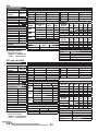
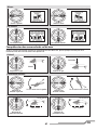
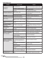
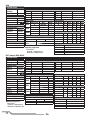
1
Instruction Manual
Bedienungsanleitung
Manuel d’utilisation
Manuale di istruzioni
RTF
NOTICE
All instructions, warranties and other collateral documents are subject to change at the sole discretion of Horizon
Hobby, LLC. For up-to-date product literature, visit horizonhobby.com and click on the support tab for this product.
Meaning of Special Language
The following terms are used throughout the product literature to indicate various levels of potential harm when
operating this product:
NOTICE: Procedures, which if not properly followed, create a possibility of physical property damage AND a little or no
possibility of injury.
CAUTION: Procedures, which if not properly followed, create the probability of physical property damage AND a possibility of serious injury.
WARNING: Procedures, which if not properly followed, create the probability of property damage, collateral damage,
and serious injury OR create a high probability of superficial injury.
WARNING: Read the ENTIRE instruction manual to become familiar with the features of the product before
operating. Failure to operate the product correctly can result in damage to the product, personal property and
cause serious injury.
This is a sophisticated hobby product. It must be operated with caution and common sense and requires some basic
mechanical ability. Failure to operate this Product in a safe and responsible manner could result in injury or damage
to the product or other property. This product is not intended for use by children without direct adult supervision. Do
not use with incompatible components or alter this product in any way outside of the instructions provided by Horizon
Hobby, LLC. This manual contains instructions for safety, operation and maintenance. It is essential to read and follow
all the instructions and warnings in the manual, prior to assembly, setup or use, in order to operate correctly and avoid
damage or serious injury.
Age Recommendation: Not for children under 14 years. This is not a toy.
Safety Precautions and Warnings
• Always keep a safe distance in all directions around
your model to avoid collisions or injury. This model is
controlled by a radio signal subject to interference from
many sources outside your control. Interference can
cause momentary loss of control.
• Always operate your model in open spaces away from
full-size vehicles, traffic and people.
• Always carefully follow the directions and warnings
for this and any optional support equipment (chargers,
rechargeable battery packs, etc.).
• Always keep all chemicals, small parts and anything
electrical out of the reach of children.
• Always avoid water exposure to all equipment not
specifically designed and protected for this purpose.
Moisture causes damage to electronics.
• Never place any portion of the model in your mouth as it
could cause serious injury or even death.
• Never operate your model with low transmitter batteries.
• Always keep aircraft in sight and under control.
• Always move the throttle fully down at rotor strike.
• Always use fully charged batteries.
• Always keep transmitter powered on while aircraft is
powered.
• Always remove batteries before disassembly.
• Always keep moving parts clean.
• Always keep parts dry.
• Always let parts cool after use before touching.
• Always remove batteries after use.
• Never operate aircraft with damaged wiring.
• Never touch moving parts.
EN
2
Table of Contents
Box Contents .................................................................... 3
Charging Warnings............................................................ 4
Battery Charging............................................................... 4
Transmitter Setup Table (BNF) ........................................... 5
Transmitter Control (RTF) .................................................. 7
Installing the Flight Battery ............................................... 7
Transmitter and Receiver Binding...................................... 8
Control Tests ..................................................................... 8
Understanding the Primary Flight Controls ........................ 9
SAFE Technology ............................................................ 10
Flight Modes ................................................................... 10
Panic Recovery ............................................................... 11
Length
200mm
Height
79mm
Airframe
Motors
Flybarless Unit
Battery
Charger
Transmitter
Transmitter Batteries
Specifications
Main Rotor Diameter
205mm
40mm
Tail Rotor Diameter
Visit www.bladehelis.com to register your helicopter
32g
Flying Weight
First Flight Preparation .................................................... 11
Flying Checklist .............................................................. 11
Flying the Nano CPS ....................................................... 11
Exploded View and Parts Listings .................................... 12
Optional Parts ................................................................. 13
Troubleshooting Guide .................................................... 14
Limited Warranty ............................................................ 15
Warranty and Service Contact Information ...................... 16
FCC Information .............................................................. 16
IC Information ................................................................. 16
Compliance Information for the European Union .............. 16
Components
Blade Nano CPS
Brushed
3-in-1 Control Unit with SAFE® technology
150mAh 1S 3.7V 45C Li-Po Battery
1S USB Li-Po Charger, 300mA
DSM2®/DSMX® Compatible Transmitter
4 AA
RTF
Included
Installed
Installed
Included
Included
MLP6DSM Included
Included
BNF
Included
Installed
Installed
Included
Included
Required
Required
Box Contents
• Blade Nano CPS
• 150mAh 1S 3.7V 45C Li-Po Battery
• 1S USB Li-Po Charger, 300mA
• DXe Transmitter (RTF Only)
• 4 AA Batteries (RTF Only)
3
EN
Charging Warnings
CAUTION: All instructions and warnings must be
followed exactly. Mishandling of Li-Po batteries can
result in a fire, personal injury and/or property damage.
• NEVER LEAVE CHARGING BATTERIES UNATTENDED.
• NEVER CHARGE BATTERIES OVERNIGHT.
• By handling, charging or using the included Li-Po battery,
you assume all risks associated with lithium batteries.
• If at any time the battery begins to balloon or swell,
discontinue use immediately. If charging or discharging,
discontinue and disconnect. Continuing to use, charge or
discharge a battery that is ballooning or swelling can result
in fire.
• Always store the battery at room temperature in a dry area
for best results.
• Always transport or temporarily store the battery in a
temperature range of 40–120º F (5–49° C).
• Do not store battery or model in a car or direct sunlight. If
stored in a hot car, the battery can be damaged or even
catch fire.
• Always charge batteries away from flammable materials.
• Always inspect the battery before charging
• Always disconnect the battery after charging, and let the
charger cool between charges
• Always constantly monitor the temperature of the battery
pack while charging.
• ONLY USE A CHARGER SPECIFICALLY DESIGNED TO
CHARGE LI-PO BATTERIES. Failure to charge the battery
with a compatible charger may cause a fire resulting in
personal injury and/or property damage.
• Never discharge Li-Po cells to below 3V under load.
• Never cover warning labels with hook and loop strips.
• Never charge batteries outside recommended levels.
• Never charge damaged batteries.
• Never attempt to dismantle or alter the charger.
• Never allow minors to charge battery packs.
• Never charge batteries in extremely hot or cold places
(recommended between 40–120° F or (5–49° C) or place
in direct sunlight.
Battery Charging
Your aircraft comes with a 1S 3.7V DC Li-Po
battery charger and 1S 3.7V 150mAh 45C Li-Po
battery. Refer to the charging warnings.
It is recommended to charge the battery pack
while you are inspecting the aircraft. The flight
battery will be required to confirm proper aircraft
operation in future steps.
NOTICE: Charge only batteries that are cool to the touch
and are not damaged. Look at the battery to make
sure it is not damaged e.g., swollen, bent, broken or
punctured.
1. Insert the charger into a USB port. The charger only
uses power from the USB port, it will not connect to
your computer. USB power supplies, such as those
used to charge cellular phones, can also be used.
2. Slide the battery into the slot on the charger and press
it into the charge jack/connector located at the bottom
of the slot. The end cap of the battery is specifically designed to allow the battery to fit into the slot one way
(usually with the label on the battery facing outward) to
prevent reverse polarity connection, however, check for
proper alignment and polarity.
3. Always disconnect the flight battery from the charger
immediately upon completion of charging.
EN
SOLID RED LED
–Charging
LED OFF
–Charge
Complete
DC Input:5.0V 350mA
EFLC1008
DC Output:4.2V 300mA
USB Li-Po
Charger
CAUTION: Only use chargers specifically
designed to charge the included Li-Po battery.
Failure to do so could result in fire, causing injury or
property damage.
CAUTION: Never exceed the recommended
charge rate.
LED Indications
When you make the connection successfully, the LED on
the charger turns solid red, indicating charging has begun.
Charging a fully discharged (not over-discharged) 150mAh
battery takes approximately 30–40 minutes. The light goes
out when the charge is complete.
Solid Red: Charging
OFF: Max Charge
CAUTION: Once charging is complete,
immediately remove the battery. Never leave
a battery connected to the charger.
4
Transmitter Setup Table (BNF)
DX6i
SETUP LIST
ADJUST LIST
Model Type
HELI
Swash Type 1 servo 90
TRAVEL ADJ
Channel
THRO
AILE
ELEV
RUDD
GYRO
PITC
REVERSE
Channel
THRO
AILE
ELEV
RUDD
GYRO
PITC
Direction
N
N
N
N
N
R
Modulation Type
AUTO DSMX-ENABLE
D/R COMBI
D/R SW
Timer
Down Timer
Switch
AILE
4:00
THR CUT
D/R & Expo
Chan
Sw Pos
0
AILE
1
0
ELEV
1
0
RUDD
1
Travel
100/100
100/100
100/100
100/100
100/100
100/100
Throttle Curve
Switch Pos Pos Pos Pos Pos Pos
(F Mode)
1
2
3
4
5
NORM
0
25 50 75 100
STUNT
100 100 100 100 100
HOLD
0
Mixing
GYRO->GYRO
ACT
Rate
D –80%
U +0%
SW
GYRO
TRIM – INH
Panic Mode Operation
Gyro Switch: Pos 0 = Panic Mode Off
Pos 1 = Panic Mode On
D/R
100
75
100
75
100
75
Pitch Curve
Switch Pos Pos
(F Mode)
1
NORM
30
STUNT
0
HOLD
0
Expo
+25
+25
+25
+25
+25
+25
Pos
2
40
25
25
GYRO
RATE SW-F.MODE
0
90%
1
15%
Pos Pos Pos
3
4
5
50 75 100
50 75 100
50 75 100
NORM
STUNT
0
1
DX7s, DX8
FUNCTION LIST
SYSTEM SETUP
Model Type
Swash Type
HELI
1 servo
Normal
F-Mode Setup
Flight Mode
F Mode
Hold
Hold
SW Select
Trainer
F Mode
Gyro
Mix
Hold
Knob
Aux 2
Gear
INH
INH
INH
INH
Frame Rate
11ms
DSMX
Servo Setup
Chan
Travel
THR
100/100
AIL
100/100
ELE
100/100
RUD
100/100
D/R & Expo
Switch Pos
(Ail D/R)
Chan DX7s
DX8
0
AILE
0
1
1
2
0
ELEV
0
1
1
2
0
RUDD
0
1
1
2
Reverse
Normal
Normal
Normal
Normal
D/R
100/100
100/100
75/75
100/100
100/100
75/75
100/100
100/100
75/75
Expo
+25
+25
+25
+25
+25
+25
+25
+25
+25
Gyro
INH
Panic Mode Operation
Trainer/Bind Button
Pressed = Panic Mode On
Released = Panic Mode Off
Mixing
Channels
Rate
Offset
Trim
Position
AUX2 > GER
100%
20%
100%
INH
N
I
H
M
5
Chan
GER
PIT
AX2
Travel
100/100
100/100
100/100
Throttle Curve
Switch Pos
(F Mode)
DX7s DX8
N
N
1
1
2
Pt 1
0
100
100
Reverse
Normal
Normal
Normal
Pt 2
25
80
100
Throttle Cut
Throttle
Pt 3
50
75
100
Pt 4
75
80
100
Pt 5
100
100
100
0%
Pitch Curve
Switch Pos
(F Mode)
DX7s DX8 Pt 1
N
N
30
1
1
0
2
0
HOLD HOLD 25
Pt 2
40
25
25
37
Timer
Mode
Time
Start
Over
Count Down
4:00 Tone
Throttle Out
25%
Pt 3
50
50
50
50
Pt 4
75
75
75
75
Pt 5
100
100
100
100
EN
DX6
FUNCTION LIST
SYSTEM SETUP
Model Type
Swash Type
HELI
Normal
F-Mode Setup
Switch 1
Switch B
Hold Switch Switch H
1
0
Channel Assign
Channel Input
1 Throttle
Throttle
2 Aileron
Aileron
3 Elevator
Elevator
4 Rudder
Rudder
5 Gear
Gear
6 AUX 1
Pitch
Servo Setup
Chan
Travel
THR
100/100
AIL
100/100
ELE
100/100
D/R & Expo
Chan Sw (F) Pos
0
AILE
1
0
ELEV
1
0
RUDD
1
D/R
100/100
75/75
100/100
75/75
100/100
75/75
Expo
+25
+25
+25
+25
+25
+25
Mixing
Rate
Offset
Switch
Frame Rate
11ms
DSMX
Reverse
Normal
Normal
Normal
GER -> GER
100%
100%
20%
Switch I
Panic Mode Operation
Bind / I Button
Pressed = Panic Mode On
Released = Panic Mode Off
Chan
RUD
GER
PIT
Travel
100/100
100/100
100/100
Reverse
Normal
Normal
Normal
Throttle Curve
Sw (B) Pos Pt 1 Pt 2 Pt 3 Pt 4 Pt 5
N
0
25 50 75 100
1
100 80 75 80 100
2
100 100 100 100 100
HOLD
0
0
0
0
0
Pitch Curve
Sw (B) Pos Pt 1 Pt 2 Pt 3 Pt 4 Pt 5
N
30
40 50 75 100
1
0
25 50 75 100
2
0
25 50 75 100
HOLD
0
25 50 75 100
Timer
Mode
Time
Start
Over
One Time
Count Down
4:00
Throttle Out
25%
Inhibit
DX7 (new), DX9, DX18
FUNCTION LIST
SYSTEM SETUP
Model Type
Swash Type
HELI
Normal
F-Mode Setup
Switch 1
Switch B
Switch 2
Inhibit
Hold Switch Switch H
0
1
Channel Assign
Channel Input
1 Throttle
Throttle
2 Aileron
Aileron
3 Elevator
Elevator
4 Rudder
Rudder
5 Gear
Switch B
6 AUX 1
INH
7 AUX 2
Frame Rate
11ms
DSMX
Panic Mode Operation
Bind / I Button
Pressed = Panic Mode On
Released = Panic Mode Off
EN
Servo Setup
Chan
Travel
THR
100/100
AIL
100/100
ELE
100/100
RUD
100/100
GER
100/100
D/R & Expo
Chan Sw (F) Pos
0
AILE
1
2
0
ELEV
1
2
0
RUDD
1
2
Reverse
Normal
Normal
Normal
Normal
Normal
D/R
100/100
100/100
75/75
100/100
100/100
75/75
100/100
100/100
75/75
Expo
+25
+25
+25
+25
+25
+25
+25
+25
+25
Mixing
Rate
Offset
Switch
GER -> GER
100%
100%
20%
Switch I
6
Chan
PIT
AX2
AX3
AX4
Travel
100/100
100/100
100/100
100/100
Reverse
Normal
Normal
Normal
Normal
Throttle Curve
Sw (B) Pos Pt 1 Pt 2 Pt 3 Pt 4
N
0
25 50 75
1
100 80 75 80
2
100 100 100 100
HOLD
0
0
0
0
Pitch Curve
Sw (B) Pos Pt 1 Pt 2 Pt 3 Pt 4
N
30
40 50 75
1
0
25 50 75
2
0
25 50 75
HOLD
0
25 50 75
Timer
Mode
Count Down
Time
4:00
Start
Throttle Out
Over
25%
One Time
Inhibit
Pt 5
100
100
100
0
Pt 5
100
100
100
100
Transmitter Control (RTF)
Flight mode
switch
Pa
Panic
R
Recovery
A
Bind switch
Dual rate switch
H
G
B
C
F
D
E
When pressed down, trim buttons make a sound that increases or decreases in pitch at each pressing. The middle or
neutral trim position is heard as a middle tone in the pitch range of the sounds. The end of the control range is sounded
by a series of beeps.
Mode 1
Mode 2
A
Power LED/
flight mode
indicator
Power LED/
flight mode
indicator
B
C
D
E
F
G
H
Aileron (Left/Right)
Throttle (Up/Down)
Throttle
Trim
Aileron
Trim
ON/OFF
Switch
Rudder
Trim
Elevator
Trim
Rudder (Left/Right)
Elevator (Up/Down)
Aileron (Left/Right)
Elevator (Up/Down)
Elevator
Trim
Aileron
Trim
ON/OFF
Switch
Rudder
Trim
Throttle
Trim
Rudder (Left/Right)
Throttle (Up/Down)
Dual Rate Selection
The control sensitivity can be changed by pressing and releasing the right control stick. The LED on the transmitter will show
solid for high sensitivity (default) and flashing for low sensitivity.
Installing the Flight Battery
1. Lower the throttle and throttle trim to the lowest settings.
2. Power on the transmitter.
3. Install the flight battery in the battery holder. Connect
the battery cable to the 3-in-1 control unit.
NOTICE: Do not allow the helicopter to move until the
blue LED on the 3-in-1 control unit is solid.
NOTICE: Always disconnect the Li-Po battery from the
3-in-1 control unit of the aircraft when not flying. Failure
to do so may result in over discharge.
7
EN
Transmitter and Receiver Binding
Binding is the process of programming the receiver of the control unit to recognize the GUID (Globally Unique Identifier)
code of a single specific transmitter. You need to ‘bind’ your chosen Spektrum™ DSM2 ®/ DSMX ® technology equipped
aircraft transmitter to the receiver for proper operation.
If you purchased an RTF model, the transmitter is bound to the model at the factory.
If for any reason you need to re-bind your Nano CPS to the MLP6DSM, follow the directions below:
Binding Procedure for the MLP6DSM (RTF)
1. Disconnect the flight battery from the helicopter.
2. Power off the transmitter and move all switches to the 0 position.
3. Connect the flight battery to the helicopter. The 3-in-1 Control unit LED flashes after 5 seconds.
4. Push and hold the “panic” trigger/button and hold the rudder control stick to full left while powering on the transmitter.
5. Release the trainer switch/button. Continue to hold the rudder control stick to full left until the blue LED on the
3-in-1 control unit is solid.
6. Release the rudder control stick.
7. Push the trainer switch/button. The blue LED on the 3-in-1 control unit flashes to confirm the helicopter
is in non-computer mode.
8. Disconnect the flight battery and power the transmitter off.
NOTICE: If the swashplate moves up and down when the trainer switch is moved, the helicopter is in computer
transmitter mode. Repeat the binding procedure.
To bind your Nano CPS to your chosen transmitter, follow the directions below:
Binding Procedure for Computer Radios (BNF)
1. Disconnect the flight battery from the helicopter.
2. Power off the transmitter and move all switches to the 0 position.
3. Connect the flight battery to the helicopter. The 3-in-1 Control unit LED flashes after 5 seconds.
4. Push the bind switch/button while powering on the transmitter.
5. After 2–3 seconds, release the bind switch/button.
6. Move the rudder control stick to full right. Continue to hold the rudder control stick to full right
until the blue LED on the 3-in-1 control unit is solid.
7. Release the rudder control stick.
8. Disconnect the flight battery and power the transmitter off.
NOTICE: The throttle will not arm if the transmitter’s throttle control is not put at the lowest position and the stunt
mode switch is not in the 0 position.
If you encounter problems, refer to the troubleshooting guide for other instructions. If needed, contact the appropriate
Horizon Hobby Product Support office.
Control Tests
Ensure the throttle hold is ON when doing the direction
control tests. Test the controls prior to the first flight to
ensure the servos, linkages and parts operate correctly.
If the controls do not react as shown in the illustrations
below, confirm the transmitter is programmed correctly.
Elevator
Left Side View
FP
O
Left Side View
Elevator down
EN
Elevator up
8
Aileron
Rear View
Aileron left
Rear View
Aileron right
Collective Pitch
Left Side View
Collective pitch up
Left Side View
Collective pitch down
Understanding the Primary Flight Controls
If you are not familiar with the controls of your Nano CPS, take a few minutes to familiarize yourself with them before
attempting your first flight.
Throttle
Left Side View
Left Side View
Descend
Climb
Throttle up
Throttle down
Rudder
Top View
Top View
Nose Yaws Left
Nose Yaws Right
Rudder left
Rudder right
Elevator
Left Side View
Left Side View
Forward
Backward
Elevator forward
Elevator back
9
EN
Aileron
Rear View
Rear View
Left
Right
Aileron left
Aileron right
Technology
Revolutionary SAFE® (Sensor Assisted Flight Envelope)
technology uses an innovative combination of multi-axis
sensors and software that allows model aircraft to know
its position relative to the horizon. This spatial awareness
is utilized to create a controlled flight envelope the aircraft
can use to maintain a safe region of bank and pitch angles
so you can fly more safely. Far beyond stability, this level of
protection offers multiple modes so the pilot can choose to
develop his or her skills with a greater degree of security and
flight control that always feels crisp and responsive.
SAFE technology delivers:
• Flight envelope protection you can enable at the flip of a
switch.
• Multiple modes let you adapt SAFE technology to your skill
level instantly.
Best of all, sophisticated SAFE technology doesn’t require
any work to enjoy. Every aircraft with SAFE installed is
ready to use and optimized to offer the best possible flight
experience.
FlySAFERC.com
Flight Modes
The Nano CPS RTF comes with the Blade MLP6DSM
transmitter. This transmitter has a flight mode switch that
lets the pilot change among the following flight modes.
Throttle Hold (switch position 0)
Throttle hold is used to turn off the helicopter motors if
the helicopter is out of control, in danger of crashing or
both. Activate throttle hold anytime the helicopter is in
danger to reduce the chance of damaging the helicopter
in a crash.
Stability Mode (switch position 1)
• Stability Mode is typically preferred by pilots with less
experience flying collective pitch helicopters.
• The helicopter will limit the bank angle, even with full
control input, and return the aircraft to a level flight attitude
when the controls are released.
• The yaw rate is slowed for ease of control.
• The Panic Recovery button returns the helicopter to upright,
level attitude.
• The throttle mode is normal.
Low throttle stick position = 0% throttle.
3D Mode (switch position 2 )
• 3D Mode is intended for pilots with experience with collective pitch helicopters.
• The model will NOT return to a level attitude position when
you release the controls.
• The helicopter has no bank angle limit.
• Both the cyclic and yaw controls are at fast, aerobatic rate.
• The Panic Recovery button returns the helicopter to a level
attitude, either upright or inverted, whichever is closer.
• The throttle mode is “Idle up.” The motor remains at a
constant speed, regardless of the throttle stick position. The
throttle stick controls the pitch of the main rotor blades.
EN
If you choose to use a computer radio, programmed as
shown in the Transmitter Setup Table section, the flight
mode switch gives the pilot the choice between the following flight modes:
Stability Mode (switch position 0) as previously described.
Agility Mode (switch position 1)
• Agility Mode shares the same characteristics as 3D Mode
with a slightly lower head speed. This results in a softer,
less responsive feel.
3D Mode (switch position 2) as previously described.
Activate Throttle Hold with the Hold switch.
10
Panic Recovery
If you get into distress while flying in any mode, push and
hold the Bind/Panic Switch and move the control sticks to
their neutral position. SAFE technology will immediately
return the aircraft to an upright level attitude, if the aircraft
is at a sufficient height with no obstacles in its path.
Return the collective stick to 50% and release the Panic
Switch to turn off Panic Recovery and return to the current
flight mode.
First Flight Preparation
NOTICE: Before releasing the panic switch, make
sure the collective stick has been returned to the 50%
position. Once the panic switch has been released, full
negative collective becomes available, which could
cause the Nano CPS to descend rapidly.
• This mode is intended to provide the pilot with the
confidence to continue to improve their flight skills.
• Move the collective stick to 50% and return all other
transmitter controls to neutral for the quickest recovery.
• Once the model has reached a level upright attitude the
negative collective is reduced preventing the user from
pushing the model into the ground.
Flying Checklist
❏
❏
❏
❏
❏
❏
❏
•
•
•
•
Remove and inspect contents
Begin charging the flight battery
Program your computer transmitter (BNF)
Install the flight battery in the helicopter
(once it has been fully charged)
• Bind your transmitter (BNF)
• Familiarize yourself with the controls
• Find a suitable area for flying
Always turn the transmitter on first
Plug the flight battery into the lead from the ESC
Allow the receiver and ESC to initialize and arm properly
Fly the model
Land the model
Unplug the flight battery from the ESC
Always turn the transmitter off last
Flying the Nano CPS
Consult your local laws and ordinances before choosing a
location to fly your aircraft.
We recommend flying your aircraft outside in calm winds
or inside a large gymnasium. Always avoid flying near
houses, trees, wires and buildings. You should also be
careful to avoid flying in areas where there are many
people, such as busy parks, schoolyards or soccer fields.
It is best to fly from a smooth flat surface as this will allow
the model to slide without tipping over. Keep the helicopter
approximately 2 ft (600mm) above the ground. Keep the
tail pointed toward you during initial flights to keep the
control orientation consistent. Releasing the stick in Beginner Mode will allow the helicopter to level itself and activating the Panic Recovery button will level the helicopter
quickly. If you become disoriented while in Beginner Mode,
slowly lower the throttle stick to land softly.
During initial flights, only attempt takeoff, landing and
hovering in one spot.
Takeoff
Place the model onto a flat, level surface free of
obstacles and walk back 30 feet (10 meters). Slowly
increase the throttle until the model is approximately 2 ft.
(600mm) off the ground and check the trim so the model
flies as desired. Once the trim is adjusted, begin flying
the model.
Hovering
Making small corrections on the transmitter, try to hold
the helicopter in one spot. If flying in calm winds, the
model should require almost no corrective inputs. After
moving the cyclic stick and returning it to center the
11
model should level itself. The model may continue to
move due to inertia. Move the cycle stick in the opposite
direction to stop the movement.
After you become comfortable hovering, you can progress into flying the model to different locations, keeping
the tail pointed towards you at all times. You can also
ascend and descend using the throttle stick. Once you’re
comfortable with these maneuvers, you can attempt
flying with the tail in different orientations. It is important
to keep in mind that the flight control inputs will rotate
with the helicopter, so always try to picture the control
inputs relative to the nose of the helicopter. For example,
forward will always drop the nose of the helicopter.
Low Voltage Cutoff (LVC)
LVC decreases the power to the motors when the battery
voltage gets low. When the motor power decreases and
the red LED on the ESC flashes, land the aircraft immediately and recharge the flight battery.
LVC does not prevent the battery from over-discharge
during storage.
NOTICE: Repeated flying to LVC will damage the battery.
Landing
To land, slowly decrease the throttle while in a low-level
hover. After landing, disconnect and remove the battery
from the aircraft after use to prevent trickle discharge.
Fully charge your battery before storing it. During storage, make sure the battery charge does not fall below
3V per cell.
EN
Exploded View and Parts Listings
17
20
24
19
19
18
19
19
20
14
22
17
15
16
14
2
21
3
1
6
5
9
21
5
10
13
23
7
12
EN
12
Description
nCP S Main board
nCP S Main motor
nCP S Main plastic frame
nCP S Tail Fin
DSV40LBC-35 Servo *1
DSV40LBC-50 Servo *1
nCP S Canopy
nCP S Tail Boom
nCP S Damping upper plastic plate
nCP S Damping ball
Tail Rotor
Landing Skid & Battery mount
Main Gear
Carbon Fiber Main Shaft with Collar &
14 BLH3307
Hardware
15 BLH3308
Servo Pushrod set with Ball Links
16 BLH3309
Complete Precision Swashplate
17 BLH3310
Main Rotor Blade Set with Hardware
18 BLH3312
Main Rotor Hub with Hardware
Feathering Spindle with O-rings and
19 BLH3313
Hardware
20 BLH3314
Main Blade Grips with Bearings
21 BLH3315
2 x 5 x 2 Bearings (2)
22 BLH3322
Rotor Head Linkage Set (4)
23 EFLB1501S45 1-Cell 3.7v 45C LiPo Battery
24 BLH3324
Spindle Tool Set
BLH3323
Hardware Set
EFLC1008
1s USB LiPo charger, 300mAh
SPM6836
Replacement Servo Mechanics
EFLRMLP6H MLP6DSM Heli SAFE transmitter
Fast Flight Main Rotor Blade Set with
BLH3311
Hardware
BLH3021
Canopy Mounting Grommets (8)
1
2
3
4
5
6
7
8
9
10
11
12
13
11
8
4
Part #
BLH2401
BLH2402
BLH2403
BLH2404
SPMSH2027L
SPMSH2028L
BLH2405
BLH2406
BLH2507
BLH2508
BLH3603
EFLH3004
BLH3306
Optional Parts
Part #
BLH3318A
BLH3320A
13
Description
Blue Canopy Set: Nano CP X
Blue Vertical Fin: Nano CP X
DX6i DSMX 6-Channel Transmitter Only
DX7s DSMX 7-Channel Transmitter Only
DX6 DSMX 6-Channel Transmitter Only
DX7 DSMX 7-Channel Transmitter Only
DX8 DSMX 8-Channel Transmitter Only
DX9 DSMX 9-Channel Transmitter Only
DX18 DSMX 18-Channel Transmitter Only
EN
Troubleshooting Guide
Problem
Possible Cause
Throttle at high position
Helicopter will not
initialize
Helicopter will not spool up
Motor power decreases
during flight
Cannot turn off throttle hold
Switches not in normal position
Pitch or throttle servo reversing
improperly configured
Throttle hold on
Low battery voltage
Receiver uses default soft Low
Voltage Cutoff (LVC)
Stunt Mode switch still on
Throttle not at low position
Solution
Reset controls with throttle stick and throttle
trim at center or lowest setting
Set flight mode to OFF/0 and exit throttle hold
Reset servo reversing
Refer to “Programming your Transmitter”
Turn off HOLD with throttle low and trim
centered or low. Refer to “Throttle Hold”
Completely recharge flight battery
Recharge the flight battery or replace if the
battery performance is poor
Set flight mode to OFF/ 0 and exit throttle hold
Reset controls with throttle stick and throttle
trim at center or lowest setting
Switch the flight mode switch to Intermediate
or Experienced Mode before flying inverted
Release bind button/ switch after applying left
rudder. Do not hold the bind button/ switch
after applying left rudder
Replace tail boom
Twist rotor blade back into position or replace
Powers off when flying
upside down (inverted)
Flight mode is set to Beginner Mode
Will not bind properly to
non-computer radio
Helicopter binds differently to
non-computer radios
Poor tail authority
Tail boom is cracked
The tail rotor blade is warped or bent
Climb out rate is greatly
reduced
Main gear has slipped on the main shaft Push main gear back into position
LED on receiver flashes
rapidly and aircraft will not
bind to transmitter
(during binding)
LED on receiver flashes
rapidly and aircraft will not
respond to transmitter (after
binding)
Transmitter is too near aircraft during
binding process
Bind switch or button was not held
while transmitter was powered on
Aircraft or transmitter is too close to
large metal object, wireless source or
another transmitter
Less than a 5-second wait between
first powering on transmitter and
connecting flight battery to aircraft
Aircraft is bound to a different model
memory (ModelMatchTM radios only)
Flight battery/transmitter battery
charge is too low
Transmitter may have been bound to
a different model (or with a different
DSM® Protocol)
Aircraft or transmitter is too close to
large metal object, wireless source or
another transmitter
Power off transmitter, move transmitter a
larger distance from aircraft, disconnect and
reconnect flight battery to aircraft and follow
binding instructions
Power off transmitter and repeat bind process
Move aircraft and transmitter to another
location and attempt binding again
Leaving transmitter on, disconnect and
reconnect flight battery to aircraft
Select correct model memory on transmitter
and disconnect and reconnect flight battery to
aircraft
Replace/recharge batteries
Select the right transmitter or bind to the new
one
Move aircraft and transmitter to another
location and attempt connecting again
Check main rotor blades and blade grips for
Helicopter vibrates or shakes Damaged rotor blades, spindle or blade
cracks or chips. Replace damaged parts.
in flight
grips
Replace bent spindle
EN
14
Limited Warranty
What this Warranty Covers
Horizon Hobby, LLC, (Horizon) warrants to the original purchaser that the product purchased (the “Product”) will be free from
defects in materials and workmanship at the date of purchase.
What is Not Covered
This warranty is not transferable and does not cover (i) cosmetic damage, (ii) damage due to acts of God, accident, misuse,
abuse, negligence, commercial use, or due to improper use,
installation, operation or maintenance, (iii) modification of or to
any part of the Product, (iv) attempted service by anyone other
than a Horizon Hobby authorized service center, (v) Product not
purchased from an authorized Horizon dealer, (vi) Product not
compliant with applicable technical regulations, or (vii) use that
violates any applicable laws, rules, or regulations.
OTHER THAN THE EXPRESS WARRANTY ABOVE, HORIZON
MAKES NO OTHER WARRANTY OR REPRESENTATION, AND
HEREBY DISCLAIMS ANY AND ALL IMPLIED WARRANTIES,
INCLUDING, WITHOUT LIMITATION, THE IMPLIED WARRANTIES
OF NON-INFRINGEMENT, MERCHANTABILITY AND
FITNESS FOR A PARTICULAR PURPOSE. THE PURCHASER
ACKNOWLEDGES THAT THEY ALONE HAVE DETERMINED THAT
THE PRODUCT WILL SUITABLY MEET THE REQUIREMENTS OF
THE PURCHASER’S INTENDED USE.
Purchaser’s Remedy
Horizon’s sole obligation and purchaser’s sole and exclusive
remedy shall be that Horizon will, at its option, either (i) service,
or (ii) replace, any Product determined by Horizon to be defective. Horizon reserves the right to inspect any and all Product(s)
involved in a warranty claim. Service or replacement decisions
are at the sole discretion of Horizon. Proof of purchase is
required for all warranty claims. SERVICE OR REPLACEMENT
AS PROVIDED UNDER THIS WARRANTY IS THE PURCHASER’S
SOLE AND EXCLUSIVE REMEDY.
Limitation of Liability
HORIZON SHALL NOT BE LIABLE FOR SPECIAL, INDIRECT,
INCIDENTAL OR CONSEQUENTIAL DAMAGES, LOSS OF
PROFITS OR PRODUCTION OR COMMERCIAL LOSS IN ANY
WAY, REGARDLESS OF WHETHER SUCH CLAIM IS BASED IN
CONTRACT, WARRANTY, TORT, NEGLIGENCE, STRICT LIABILITY
OR ANY OTHER THEORY OF LIABILITY, EVEN IF HORIZON HAS
BEEN ADVISED OF THE POSSIBILITY OF SUCH DAMAGES.
Further, in no event shall the liability of Horizon exceed the
individual price of the Product on which liability is asserted. As
Horizon has no control over use, setup, final assembly, modification or misuse, no liability shall be assumed nor accepted
for any resulting damage or injury. By the act of use, setup
or assembly, the user accepts all resulting liability. If you as
the purchaser or user are not prepared to accept the liability
associated with the use of the Product, purchaser is advised to
return the Product immediately in new and unused condition to
the place of purchase.
Law
These terms are governed by Illinois law (without regard to
conflict of law principals). This warranty gives you specific
legal rights, and you may also have other rights which vary
from state to state. Horizon reserves the right to change or
modify this warranty at any time without notice.
WARRANTY SERVICES
Questions, Assistance, and Services
Your local hobby store and/or place of purchase cannot provide
warranty support or service. Once assembly, setup or use of
the Product has been started, you must contact your local
distributor or Horizon directly. This will enable Horizon to better
answer your questions and service you in the event that you
may need any assistance. For questions or assistance, please
visit our website at www.horizonhobby.com, submit a Product
Support Inquiry, or call the toll free telephone number referenced in the Warranty and Service Contact Information section
to speak with a Product Support representative.
Inspection or Services
If this Product needs to be inspected or serviced and is compliant in the country you live and use the Product in, please use
the Horizon Online Service Request submission process found
on our website or call Horizon to obtain a Return Merchandise
Authorization (RMA) number. Pack the Product securely
using a shipping carton. Please note that original boxes may
be included, but are not designed to withstand the rigors of
shipping without additional protection. Ship via a carrier that
provides tracking and insurance for lost or damaged parcels,
as Horizon is not responsible for merchandise until it arrives
and is accepted at our facility. An Online Service Request is
available at http://www.horizonhobby.com/content/_servicecenter_render-service-center. If you do not have internet
access, please contact Horizon Product Support to obtain
a RMA number along with instructions for submitting your
product for service. When calling Horizon, you will be asked
to provide your complete name, street address, email address
and phone number where you can be reached during business
hours. When sending product into Horizon, please include your
RMA number, a list of the included items, and a brief summary
of the problem. A copy of your original sales receipt must
be included for warranty consideration. Be sure your name,
address, and RMA number are clearly written on the outside of
the shipping carton.
NOTICE: Do not ship Li-Po batteries to Horizon. If you have
any issue with a Li-Po battery, please contact the appropriate
Horizon Product Support office.
Warranty Requirements
For Warranty consideration, you must include your original sales receipt verifying the proof-of-purchase date.
Provided warranty conditions have been met, your Product will
be serviced or replaced free of charge. Service or replacement
decisions are at the sole discretion of Horizon.
Non-Warranty Service
Should your service not be covered by warranty, service will be completed and payment will be required
without notification or estimate of the expense unless
the expense exceeds 50% of the retail purchase cost.
By submitting the item for service you are agreeing to payment of the service without notification. Service estimates are
available upon request. You must include this request with your
item submitted for service. Non-warranty service estimates
will be billed a minimum of ½ hour of labor. In addition you
will be billed for return freight. Horizon accepts money orders
and cashier’s checks, as well as Visa, MasterCard, American
Express, and Discover cards. By submitting any item to Horizon
for service, you are agreeing to Horizon’s Terms and Conditions
found on our website http://www.horizonhobby.com/content/_
service-center_render-service-center.
ATTENTION: Horizon service is limited to Product compliant in the country of use and ownership. If received,
a non-compliant Product will not be serviced. Further,
the sender will be responsible for arranging return
shipment of the un-serviced Product, through a carrier
of the sender’s choice and at the sender’s expense.
Horizon will hold non-compliant Product for a period
of 60 days from notification, after which it will be discarded.
15
EN
Warranty and Service Contact Information
Country of
Purchase
Horizon Hobby
Contact Information
Address
Horizon Service Center
servicecenter.horizonhobby.com/
(Repairs and Repair Requests) RequestForm/
[email protected]
Horizon Product Support
(Product Technical Assistance) 888-959-2304
[email protected]
Sales
888-959-2304
[email protected]
Service/Parts/Sales:
Horizon Hobby Limited
+44 (0) 1279 641 097
Units 1–4 , Ployters Rd, Staple Tye
Harlow, Essex, CM18 7NS, United
Kingdom
Germany
Horizon Technischer Service
Sales: Horizon Hobby GmbH
Christian-Junge-Straße 1
25337 Elmshorn, Germany
France
Service/Parts/Sales:
Horizon Hobby SAS
China
Service/Parts/Sales:
Horizon Hobby – China
United States of
America
United Kingdom
[email protected]
+49 (0) 4121 2655 100
[email protected]
+33 (0) 1 60 18 34 90
[email protected]
+86 (021) 5180 9868
4105 Fieldstone Rd
Champaign, Illinois, 61822 USA
11 Rue Georges Charpak
77127 Lieusaint, France
Room 506, No. 97 Changshou Rd.
Shanghai, China 200060
Compliance Information for the European Union
EU Compliance Statement:
Horizon Hobby, LLC hereby declares that this
product is in compliance with the essential
requirements and other relevant provisions of the R&TTE,
EMC, and LVD Directives.
A copy of the EU Declaration of Conformity is available
online at: http://www.horizonhobby.com/content/supportrender-compliance.
Instructions for disposal of WEEE by users in the European Union
This product must not be disposed of
with other waste. Instead, it is the user’s
responsibility to dispose of their waste
equipment by handing it over to a designated collections point for the recycling of
waste electrical and electronic equipment.
The separate collection and recycling of
EN
your waste equipment at the time of disposal will help to
conserve natural resources and ensure that it is recycled in
a manner that protects human health and the environment.
For more information about where you can drop off your
waste equipment for recycling, please contact your local
city office, your household waste disposal service or where
you purchased the product.
16
17
EN
HINWEIS
Alle Anweisungen, Garantien und anderen zugehörigen Dokumente können im eigenen Ermessen von Horizon Hobby,
LLC jederzeit geändert werden. Die aktuelle Produktliteratur finden Sie auf horizonhobby.com unter der Registerkarte
„Support“ für das betreffende Produkt.
Spezielle Bedeutungen
Die folgenden Begriffe werden in der gesamten Produktliteratur verwendet, um auf unterschiedlich hohe Gefahrenrisiken beim Betrieb dieses Produkts hinzuweisen:
HINWEIS: Wenn diese Verfahren nicht korrekt befolgt werden, können sich möglicherweise Sachschäden UND geringe oder keine Gefahr von Verletzungen ergeben.
ACHTUNG: Wenn diese Verfahren nicht korrekt befolgt werden, ergeben sich wahrscheinlich Sachschäden UND die
Gefahr von schweren Verletzungen.
WARNUNG: Wenn diese Verfahren nicht korrekt befolgt werden, ergeben sich wahrscheinlich Sachschäden,
Kollateralschäden und schwere Verletzungen ODER mit hoher Wahrscheinlichkeit oberflächliche Verletzungen.
WARNUNG: Lesen Sie die GESAMTE Bedienungsanleitung, um sich vor dem Betrieb mit den Produktfunktionen
vertraut zu machen. Wird das Produkt nicht korrekt betrieben, kann dies zu Schäden am Produkt oder persönlichem Eigentum führen oder schwere Verletzungen verursachen.
Dies ist ein hochentwickeltes Hobby-Produkt. Es muss mit Vorsicht und gesundem Menschenverstand betrieben werden
und benötigt gewisse mechanische Grundfähigkeiten. Wird dieses Produkt nicht auf eine sichere und verantwortungsvolle Weise betrieben, kann dies zu Verletzungen oder Schäden am Produkt oder anderen Sachwerten führen. Dieses
Produkt eignet sich nicht für die Verwendung durch Kinder ohne direkte Überwachung eines Erwachsenen. Versuchen
Sie nicht ohne Genehmigung durch Horizon Hobby, LLC das Produkt zu zerlegen, es mit inkompatiblen Komponenten
zu verwenden oder auf jegliche Weise zu erweitern. Diese Bedienungsanleitung enthält Anweisungen für Sicherheit,
Betrieb und Wartung. Es ist unbedingt notwendig, vor Zusammenbau, Einrichtung oder Verwendung alle Anweisungen
und Warnhinweise im Handbuch zu lesen und zu befolgen, damit es bestimmungsgemäß betrieben werden kann und
Schäden oder schwere Verletzungen vermieden werden.
Nicht geeignet für Kinder unter 14 Jahren. Dies ist kein Spielzeug.
Sicherheitsvorkehrungen und Warnhinweise
• Halten Sie stets in allen Richtungen einen Sicherheitsabstand um Ihr Modell, um Zusammenstöße oder Verletzungen zu vermeiden. Dieses Modell wird von einem
Funksignal gesteuert, das Interferenzen von
vielen Quellen außerhalb Ihres Einflussbereiches unterliegt. Diese Interferenzen können einen augenblicklichen
Steuerungsverlust verursachen.
• Betreiben Sie Ihr Modell immer auf einer Freifläche ohne
Fahrzeuge in voller Größe, Verkehr oder Menschen.
• Befolgen Sie stets sorgfältig die Anweisungen und
Warnhinweise für das Modell und jegliche optionalen
Hilfsgeräte (Ladegeräte, Akkupacks usw.).
• Bewahren Sie alle Chemikalien, Klein- und Elektroteile
stets außerhalb der Reichweite von Kindern auf.
• Setzen Sie Geräte, die für diesen Zweck nicht speziell
ausgelegt und geschützt sind, niemals Wasser aus.
Feuchtigkeit kann die Elektronik beschädigen.
• Stecken Sie keinen Teil des Modells in den Mund, da dies
zu schweren Verletzungen oder sogar zum Tod führen
kann.
• Betreiben Sie Ihr Modell nie mit fast leeren Senderakkus.
• Halten Sie das Fluggerät immer in Sicht und unter
Kontrolle.
• Gehen Sie sofort auf Motor Aus bei Rotorberührung.
• Verwenden Sie immer vollständig geladene Akkus.
• Lassen Sie immer den Sender eingeschaltet wenn das
Fluggerät eingeschaltet ist.
• Nehmen Sie vor der Demontage des Fluggerätes die
Akkus heraus.
• Halten Sie bewegliche Teile immer sauber.
• Halten Sie die Teile immer trocken.
• Lassen Sie Teile immer erst abkühlen bevor Sie sie
anfassen.
• Nehmen Sie die Akkus/Batterien nach Gebrauch heraus.
• Betreiben Sie Ihr Fluggerät niemals mit beschädigter
Verkabelung.
• Fassen Sie niemals bewegte Teile an.
DE
18
Inhaltsangabe
Lieferumfang .................................................................. 19
Akku-Warnhinweise ........................................................ 20
Laden des Flugakkus ...................................................... 20
Sendereinstellungen (BNF) .............................................. 21
Senderfunktionen (RTF)................................................... 23
Einsetzen des Flugakkus................................................. 23
Binden von Sender und Empfänger ................................. 24
Kontrolltests.................................................................... 24
Einführung in die Hauptsteuerfunktionen......................... 25
SAFE Technologie ........................................................... 26
Flugmodes...................................................................... 26
Spezifikationen
200mm
Hauptrotordurchmesser
79mm
Heckrotordurchmesser
Länge
Höhe
205mm
40mm
Sie können Ihr Produkt online unter
www.bladehelis.com registrieren.
32g
Fluggewicht
Rumpf
Motor
Flybarless Kontrollboard
Akku
Ladegerät
Sender
Sender Akku
Panikrettung ................................................................... 27
Vorbereitung für den Erstflug .......................................... 27
Checkliste zum Fliegen ................................................... 27
Fliegen des Nano CPS ..................................................... 27
Explosionszeichnung und Teileliste.................................. 28
Optionale Teile ................................................................ 29
Leitfaden zur Problemlösung........................................... 30
Garantie und Service Informationen ................................ 31
Garantie und Service Kontaktinformationen..................... 32
Rechtliche Informationen für die Europäische Union ........ 32
Ausstattung
RTF
BNF
Blade Nano CPS
Inklusive
Inklusive
Brushed
Eingebaut
Eingebaut
3-in-1 Kontrollboard mit SAFE Technologie
Eingebaut
Eingebaut
150mAh 1S 3.7V 45C Li-Po Akku
Inklusive
Inklusive
1S USB Li-Po Ladegerät, 300mA
Inklusive
Inklusive
DSM2 / DSMX Kompatibler Sender
MLP6DSM Inklusive Erforderlich
4 AA
Inklusive
Erforderlich
Lieferumfang
• Blade Nano CPS
• 150mAh 1S 3.7V 45C Li-Po Akku
• 1S USB Li-Po Ladegerät, 300mA
• DXe Sender (nur RTF)
• 4 AA Batterien (nur RTF)
19
DE
Akku-Warnhinweise
ACHTUNG: Alle Anweisungen und Warnhinweise
müssen genau befolgt werden. Falsche Handhabung von Li-Po-Akkus kann zu Brand, Personen- und/oder
Sachwertschäden führen.
• LASSEN SIE LADEN VON AKKUS UNBEAUFSICHTIGT.
• LADEN SIE NIEMALS AKKUS ÜBER NACHT.
• Durch Handhabung, Aufladung oder Verwendung des
mitgelieferten Li-Po-Akkus übernehmen Sie alle mit
Lithiumakkus verbundenen Risiken.
• Sollte der Akku zu einem beliebigen Zeitpunkt beginnen,
sich aufzublähen oder anzuschwellen, stoppen Sie die
Verwendung unverzüglich. Falls dies beim Laden oder Entladen auftritt, stoppen Sie den Lade-/Entladevorgang, und
entnehmen Sie den Akku. Wird ein Akku, der sich aufbläht
oder anschwillt, weiter verwendet, geladen oder entladen,
besteht Brandgefahr.
• Lagern Sie den Akku stets bei Zimmertemperatur an einem
trockenen Ort.
• Bei Transport oder vorübergehender Lagerung des Akkus
muss der Temperaturbereich zwischen 40°F und 120°F
(ca. 5 – 49°C) liegen.
• Akku oder Modell dürfen nicht im Auto oder unter direkter
Sonneneinstrahlung gelagert werden. Bei Lagerung in
einem heißen Auto kann der Akku beschädigt werden oder
sogar Feuer fangen.
• Laden Sie die Akkus immer weit entfernt von brennbaren
Materialien.
• Überprüfen Sie immer den Akku vor dem Laden und laden
Sie niemals defekte oder beschädigte Akkus.
• Verwenden Sie ausschließlich ein Ladegerät das speziell
für das Laden von LiPo Akku geeignet ist. Das Laden mit
einem nicht geeignetem Ladegerät kann Feuer und / oder
Sachbeschädigung zur Folge haben.
• Überwachen Sie ständig die Temperatur des Akkupacks
während des Ladens.
• Trennen Sie immer den Akku nach dem Laden und lassen
das Ladegerät abkühlen.
• Entladen Sie niemals ein LiPo Akku unter 3V pro Zelle unter
Last.
• Verdecken Sie niemals Warnhinweise mit Klettband.
• Lassen Sie niemals Akkus während des Ladens unbeaufsichtigt.
• Laden Sie niemals Akkus ausserhalb ihrer sicheren Grenzen.
• Versuchen Sie nicht das Ladegerät zu demontieren oder
zu verändern.
• Lassen Sie niemals Minderjährige Akkus laden.
• Laden Sie niemals Akkus an extrem kalten oder heißen
Plätzen (empfohlener Temperaturbereich 5 – 49°) oder im
direkten Sonnenlicht.
Laden des Flugakkus
Der Helikopter wird mit einem 1S 3.7V Lipo
Ladegerät und einem 1S 3.7V 150mAh 45C Lipo
Akku geliefert. Bitte lesen Sie sich die Warnhinweise zum Thema Akkuladen durch. Es wird
empfohlen, den Akku während der Zeit zu laden,
in der Sie das Fluggerät inspizieren. Der Akku
wird gebraucht, um bestimmte Funktionen später
nach Anleitung durchzuführen.
HINWEIS: Laden Sie Akkus nur, wenn sie auf Umgebungstemperatur abgekühlt sind. Schauen Sie sich
den Akku an und stellen Sie sicher, dass dieser nicht
beschädigt oder aufgequollen ist.
1. Stecken Sie den Lader in den USB Port. Der Lader
verwendet nur die Stromversorgung des USB Ports,
verbindet sich aber nicht mit Ihrem Computer. USB
Ladestationen für das Laden von Mobiltelefonen sind
ebenfalls geeignet.
2. Stecken Sie den Akku in den Akkuschacht des Laders
und drücken sie ihn fest gegen den Stecker am Boden
des Schachts. Die Schutzkappe des Akkus ist so geformt, dass der Akku nur in der richtigen Ausrichtung in
den Schacht gesteckt werden kann. In der Regel zeigt
das Label des Akkus nach oben. Somit kann der Akku
nur mit der richtigen Polarität in den Lader gesteckt
werden. Prüfen Sie die richtige Polarität.
3. Entnehmen Sie den Akku immer aus dem Lader, sobald
der Ladevorgang beendet ist.
DE
SOLID RED LED
–Charging
LED OFF
–Charge
Complete
DC Input:5.0V 350mA
DC Output:4.2V 300mA EFLC1008
USB Li-Po
Charger
ACHTUNG: Verwenden Sie nur Ladegeräte, die
für LIPO Akkus vorgesehen sind. Nichtbeachtung kann zu Feuer, Beschädigungen oder Verletzungen
führen.
ACHTUNG: Überschreiten Sie niemals die
vorgesehene Ladezeit.
LED Anzeigen
Bei erfolgreicher Verbindung von Akku und Lader leuchtet
die LED rot und zeigt an, dass der Ladevorgang begonnen
hat. Das Laden eines vollständig entladenen Akkus von
150mAh dauert ca. 30 bis 40 Minuten. Die LED erlischt,
wenn der Akku vollständig geladen ist.
Laden: LED rot
Fertig geladen: LED aus
ACHTUNG: Entnehmen Sie den Akku aus dem
Lader, sobald dieser fertig geladen ist. Belassen
Sie den Akku niemals im Lader.
20
Sendereinstellungen (BNF)
DX6i
Setup Liste
Einstellungen
Model Type
HELI
Swash Type 1 servo 90
TRAVEL ADJ
Channel
THRO
AILE
ELEV
RUDD
GYRO
PITC
REVERSE
Channel
THRO
AILE
ELEV
RUDD
GYRO
PITC
Direction
N
N
N
N
N
R
Modulation Type
AUTO DSMX-ENABLE
D/R COMBI
D/R SW
Uhr
Down Timer
Switch
AILE
4:00
THR CUT
Travel
100/100
100/100
100/100
100/100
100/100
100/100
D/R & Expo
Chan
Sw Pos
0
AILE
1
0
ELEV
1
0
RUDD
1
Gaskurve
Switch Pos Pos Pos Pos Pos Pos
(F Mode)
1
2
3
4
5
NORM
0
25 50 75 100
STUNT
100 100 100 100 100
HOLD
0
D/R
100
75
100
75
100
75
Pitchkurve
Switch Pos Pos
(F Mode)
1
NORM
30
STUNT
0
HOLD
0
Mixing
GYRO
GYRO->GYRO
ACT
RATE SW-F.MODE
Rate
D –80%
U +0%
0
90%
SW
GYRO
TRIM – INH
1
15%
Panik Modeschalter
Gyro Switch: Schalter Pos 0 = Panikmode Aus
Pos 1 = Panikmode Ein
Pos
2
40
25
25
Expo
+25
+25
+25
+25
+25
+25
Pos Pos Pos
3
4
5
50 75 100
50 75 100
50 75 100
NORM
STUNT
0
1
DX7s, DX8
Systemeinstellung
Modelltyp
Taumelscheibentyp
HELI
1 servo
Normal
Flugzustand Setup
Flugzustand
F Mode
Halt
Hold
Schalterauswahl
1 Trainer
Aux 2 (K7)
2 F Mode
FW
3 Gyro
AUS
4 Mix
AUS
5 Hold
AUS
6 Knob
AUS
Pulsrate
11ms
DSMX
Funktionsliste
Servo Setup
Kanal
Servoweg
Gas
100/100
AIL
100/100
ELE
100/100
RUD
100/100
D/R & Expo
Schalter Position
(Ail D/R)
Kanal DX7s
DX8
0
AILE
0
1
1
2
0
ELEV
0
1
1
2
0
RUDD
0
1
1
2
Laufrichtung
Normal
Normal
Normal
Normal
D/R
100/100
100/100
75/75
100/100
100/100
75/75
100/100
100/100
75/75
Expo
+25
+25
+25
+25
+25
+25
+25
+25
+25
Gyro/Kreisel
AUS
Panikmode Funktion
Trainer Binde Button
Gedrückt = Panikmode Ein
Gelöst = Panikmode Aus
Mischer
Kanäle
Rate
Offset
Trim
Position
AUX2 > GER
100%
20%
100%
AUS
N
I
H
M
21
Kanal
GER
PIT
AX2
Servoweg
100/100
100/100
100/100
Gaskurve
Schalter Position
(F Mode)
DX7s
DX8
N
N
1
1
2
Laufrichtung
Normal
Normal
Normal
Pt 1 Pt 2
0 25
100 80
100 100
Pt 3
50
75
100
Pt 4
75
80
100
Pt 5
100
100
100
Gas aus
Gas
Pitchkurve
Schalter Position
(F Mode)
DX7s
DX8
N
N
1
1
2
HOLD HOLD
Uhr
Mode
Time
Start
Über
0%
Pt 1
30
0
0
25
Pt 2
40
25
25
37
Pt 3
50
50
50
50
Pt 4
75
75
75
75
Pt 5
100
100
100
100
Count Down
4:00 Tone
Gas über
25%
DE
DX6
Systemeinstellung
Funktionsliste
Modelltyp
Taumelscheibe
Servoeinstellung
Kanäle
Weg
Gas
100/100
Quer
100/100
Höhe
100/100
HELI
Normal
F-Mode Setup
Schalter 1
Schalter B
Halt Schalter Schalter H
1
0
Channel Assign
Channel Input
THRO
AILE
ELEV
RUDD
GEAR
AUX 1
Gas
Quer
Höhe
Seite
Fahrw
PIT
Pulsrate
11ms
DSMX
Panikmode Funktion
Trainer Binde Button
Gedrückt = Panikmode Ein
Gelöst = Panikmode Aus
Mischer
Rate
Offset
Schalter
Gaskurve
Schalter
D/R
Expo
(B) Pos
N
100/100 +25
1
75/75
+25
2
100/100 +25
HOLD
75/75
+25
100/100 +25 Pitchkurve
Schalter
75/75
+25
(B) Pos
N
GER -> GER
1
100%
100%
2
20%
HOLD
Schalter I
Uhr
Mode
Time
Start
Over
Einmal
Systemeinstellung
Funktionsliste
Modelltyp
Taumelscheibe
Servoeinstellung
Kanal
Weg
Gas
100/100
Quer
100/100
Höhe
100/100
Seite
100/100
FW
100/100
Normal
Flugzustand Setup
Schalter 1
Switch B
Schalter 2
Inhibit
Halt Schalter Switch H
0
1
Kanalzuweisung
Kanalquelle
THRO
Gas
AILE
Quer
ELEV
Höhe
RUDD
Seite
GEAR
Fahrw
AUX 1
PIT
AUX 2
11ms
DSMX
Panikmode Funktion
Trainer Binde Button
Gedrückt = Panikmode Ein
Gelöst = Panikmode Aus
DE
D/R & Expo
Chan Sw (F) Pos
0
Quer
1
2
0
Höhe
1
2
0
Seite
1
2
Umkehr
Normal
Normal
Normal
Normal
Normal
D/R
100/100
100/100
75/75
100/100
100/100
75/75
100/100
100/100
75/75
Expo
+25
+25
+25
+25
+25
+25
+25
+25
+25
Mischer
Pulsrate
Kanäle
Seite
FW
PIT K6
D/R & Expo
Schalter (F)
Kanäle
Pos
0
Quer
1
0
Höhe
1
0
Seite
1
DX7 (neu), DX9, DX18
HELI
Umkehr
Normal
Normal
Normal
Rate
Offset
Schalter
GER -> GER
100%
100%
20%
Schalter I
22
Kanal
PIT K6
AX2
AX3
AX4
Gaskurve
Schalter
(B) Pos
N
1
2
HOLD
Weg
100/100
100/100
100/100
Umkehr
Normal
Normal
Normal
Pt 1 Pt 2 Pt 3 Pt 4
0
25 50 75
100 80 75 80
100 100 100 100
0
0
0
0
Pt 5
100
100
100
0
Pt 1 Pt 2 Pt 3 Pt 4
30
40 50 75
0
25 50 75
0
25 50 75
0
25 50 75
Pt 5
100
100
100
100
Count Down
4:00
Gas über
25%
Aus
Weg
100/100
100/100
100/100
100/100
Umkehr
Normal
Normal
Normal
Normal
Pt 1 Pt 2 Pt 3 Pt 4
0
25 50 75
100 80 75 80
100 100 100 100
0
0
0
0
Pt 5
100
100
100
0
Pitchkurve
Schalter
(B) Pos
Pt 1 Pt 2 Pt 3 Pt 4
N
30
40 50 75
1
0
25 50 75
2
0
25 50 75
HOLD
0
25 50 75
Pt 5
100
100
100
100
Uhr
Mode
Time
Start
Over
Einmal
Count Down
4:00
Gas über
25%
Aus
Senderfunktionen (RTF)
Auswahl
Flugmodus
Pa
Panik
Sc
Schalter
A
Auswahl
Dual Rate
Binden
H
G
B
C
F
D
E
Wenn die Trimmtasten gedrückt werden, geben sie einen Signalton von sich, der bei jedem erneuten Drücken höher
oder tiefer wird. Die mittlere oder neutrale Trimmstellung erklingt in der mittleren Tonhöhe. An den äußeren Enden des
Steuerbereichs erklingt eine Tonfolge.
A
B
C
Ein/Aus-LED, Querruder
Modus
Flugmodus (links/rechts) Gastrimm
1
Anzeige
Gas (auf/ab)
D
E
F
G
H
Seitenruder
Querruder- EIN/AUS- Seitenruder- Höhenruder- (links/rechts)
trimm
Schalter trimm
trimm
Höhenruder
(auf/ab)
Querruder
Ein/Aus-LED,
Modus
(links/rechts) Höhenruder- Querruder- EIN/AUS- SeitenruderFlugmodus
Gastrimm
2
Höhenruder trimm
trimm
Schalter trimm
Anzeige
(auf/ab)
Seitenruder
(links/rechts)
Gas (auf/ab)
Sensivität der Kontrollen
Die Sensivität der Kontrollen kann durch drücken und lösen des rechten Steuerknüppels geändert werden. Die LED auf dem
Sender leuchtet für hohe Sensivität (Standard) und blinkt für niedrige Sensivität.
Einsetzen des Flugakkus
1. Bringen Sie den Gasstick und die Trimmung ganz nach
unten (niedrigste Leerlaufposition).
2. Schalten Sie den Sender ein.
3. Setzen Sie den Flugakku in den Akkuhalter ein. Verbinden Sie das Akkuanschlußkabel mit dem Kabel des 3
-1 Kontrollboards.
HINWEIS: Der Hubschrauber darf sich nicht bewegen,
bis die LED auf dem 3- in 1 Kontrollboard konstant
leuchtet.
HINWEIS: Trennen Sie nach dem Fliegen immer den
LiPo Akku vom 3 – in 1 Kontrollboard. Tun Sie dieses
nicht wird der Akku unbrauchbar.
23
DE
Binden von Sender und Empfänger
Binden ist der Prozess der Übermittlung des Senderspezifischen Signals (GUID) (Globally Unique Identifier) an den Empfänger. Für den Betrieb muß ein Empfänger an den gewählten Spektrum DSM2/DSMX Sender/ Modul gebunden werden.
Wenn Sie ein RTF Modell gekauft haben ist der Sender ab Werk mit dem Empfänger gebunden.
Um den Helikopter an Ihren Sender neu oder erneut zu binden, folgen Sie bitte diesen Anweisungen:
Bindevorgang für den MLP6DSM Sender (RTF)
1. Trennen Sie den Flugakku vom Helikopter.
2. Schalten Sie den Sender aus und bringen alle Schalter in die 0 Position.
3. Schließen Sie den Akku an das 3 – 1 Kontrollboard an. Das 3 – in 1 Kontrollboard blinkt nach 5 Sekunden.
4. Bewegen Sie den Seitenruderknüppel ganz nach links. Drücken und halten Sie den Panikschalter bei dem Einschalten des Senders gedrückt.
5. Lassen Sie den Trainer Schalter los. Halten Sie weiterhin den Seitenruderknüppel ganz nach links gedrückt, bis die
blaue LED dauerhaft leuchtet.
6. Lassen Sie den Seitenruderknüppel los.
7. Drücken Sie den Trainerschalter ein. Die blaue LED auf dem 3 in 1 Kontrollboard blinkt um zu bestätigen der Hubschrauber ist im Nicht Computer Mode.
8. Trennen Sie den Flugakku und schalten den Sender aus.
HINWEIS: Sollte sich die Taumelscheibe bei dem Schalten des Trainerschalters rauf und runter bewegen ist der
Hubschrauber im Computer Sender Mode. Wiederholen Sie dann den Bindevorgang.
Um den Nano CPS an ihren Sender zu binden folgen Sie bitte untenstehenden Anweisungen:
Beschreibung des Bindeprozess für Computer Sender (BNF)
1. Trennen Sie den Flugakku vom Helikopter.
2. Schalten Sie den Sender aus und bringen alle Schalter in die 0 Position.
3. Schließen Sie den Akku an das 3 – 1 Kontrollboard an. Das 3 – in 1 Kontrollboard blinkt nach 5 Sekunden.
4. Drücken Sie den Bind Schalter oder Knopf während Sie den Sender einschalten.
5. Lassen Sie den Trainer Schalter los nach 2–3 Sekunden.
6. Bewegen Sie den Seitenruderknüppel ganz nach rechts. Halten Sie weiterhin den Seitenruderknüppel ganz nach
rechts gedrückt, bis die blaue LED dauerhaft leuchtet.
7. Lassen Sie den Seitenruderknüppel los.
8. Trennen Sie den Flugakku und schalten den Sender aus.
HINWEIS: Der Regler wird sich nicht armieren, wenn der Gaskanal nicht in die unterste Stellung gebracht wird und der
Stunt Mode Schalter nicht in die Position 0 geschaltet ist.
Sollten Probleme auftreten lesen Sie bitte im Leitfaden zur Problemlösung nach. Kontaktieren Sie falls notwendig den
technischen Service von Horizon Hobby.
Kontrolltests
Versichern Sie sich, dass die Gas aus Funktion
aktiviert wurde wenn Sie den Kontrolltest durchführen. Führen Sie diesen Test vor dem ersten Flug durch
um sicher zu stellen, dass die Servos, Anlenkungen und
andere Komponenten korrekt arbeiten.
Sollten die Kontrollen nicht wie den Abbildungen arbeiten
überprüfen Sie bitte, dass der Sender korrekt programmiert wurde bevor Sie den Motortest durchführen.
Höhenruder
Links Seitenansicht
FP
O
Links Seitenansicht
Höhenruder nach unten
DE
Höhenruder nach oben
24
Querruder
Rückansicht
Querruder nach links
Rückansicht
Querruder nach rechts
Kollektive Pitch
Links Seitenansicht
Kollektive Pitch oben
Links Seitenansicht
Kollektive Pitch unten
Einführung in die Hauptsteuerfunktionen
Wenn Ihnen die Steuerung Ihres Nano CPS noch nicht geläufig ist, nehmen Sie sich bitte ein paar Minuten Zeit, um sich
mit ihr vertraut zu machen, bevor Sie Ihren ersten Flug versuchen.
Gas
Links Seitenansicht
Links Seitenansicht
Sinken
Aufsteigen
Kollektive Pitch oben
Kollektive Pitch unten
Seitenruder
Aufsicht
Aufsicht
Nase dreht nach links
Seitenruder nach links
Nase dreht nach rechts
Seitenruder nach rechts
Höhenruder
Links Seitenansicht
Links Seitenansicht
Vorwärts
Rückwärts
Höhenruder nach unten
Höhenruder nach oben
25
DE
Querruder
Rückansicht
Rückansicht
Links
Querruder nach links
Rechts
Querruder nach rechts
Technologie
Die revolutionäre SAFE Technologie von Horizon Hobby
(Sensor Assited Flight Envelope) verwendet eine innovative
Kombination aus Multi-Achs Sensoren und Software, die es
erlauben, die relative Position des Fluggerätes im Raum jederzeit zu bestimmen. Diese dreidimensionale Wahrnehmung
schafft eine schräglagenbegrenzte Fluglage die Sie sicherer
Fliegen läßt. Dabei werden Roll- und Nickwinkel beeinflusst
und geregelt, um die Flugsicherheit zu erhöhen. Und das
System kann weit mehr, als die Stabilisierung des Fluggerätes.
Die verschiedenen Flugmodi können vom Piloten gemäß
seiner Fähigkeiten individuell eingestellt werden.
SAFE Technologie im Überblick:
• Flugstabilisierung über einen Schalter zuschaltbar.
• Mehrere Modi zur Anpassung von SAFE and die Fähigkeiten
des Piloten.
Und das Beste an allem ist, dass SAFE keine weiteren Einstellungen und Vorbereitungen erfordert. Jedes Modell, welches
mit SAFE ausgestattet wurde, verfügt über eine angepasste
und optimierte Programmierung der Elektronik, um für maximale Sicherheit und maximalen Flugspaß zu sorgen.
FLYSAFERC.com
Flugmodes
Der Nano CPS RTF wird mit dem Blade MLP6DSM Sender
geliefert. Der Sender ist mit einem Flugzustandsschalter
ausgerüstet, der dem Piloten die Wahl zwischen den
folgenden Flugzuständen (Flight Modes ) läßt:
Gas aus (Schalter Position 0)
Die Gas aus Funktion wird genutzt wenn der
Hubschrauber außer Kontrolle gerät und /oder die Gefahr
eines Absturzes droht. Aktivieren Sie die diese Funktion
immer bei Gefahr um mögliche Beschädigungen bei
einem Crash am Hubschrauber zu minimieren.
Stabilitäts Mode (Schalter Position 1)
• Der Stabilitäts Mode eignet sich sehr gut für Piloten die
wenig Flugerfahrungen mit kollektiv Pitch gesteuerten
Hubschraubern haben.
• Der Hubschrauber ist in der Schräglage selbst bei vollem
Knüppelausschlag limitert und kehrt bei dem Lösen der
Kontrollen in eine aufrechte Fluglage zurück.
• Für eine leichtere Kontrolle ist die Drehrate bei dem Gieren
reduziert.
• Der Panikbutton bringt den Hubschrauber zurück in eine
aufrechte Fluglage.
• Der Gasmode ist normal
Die unterste Knüppelposition ist = 0% Gas.
• Der Gas Mode ist Idle up. Der Hauptrotor hält eine konstante
Drehzahl unabhängig von der Stellung des Gas/ Pitchhebels. Der Gast /Pitchhebel kontrolliert nur den Pitchwinkel
der Rotorblätter.
Bei Verwendung einer Computerfernsteuerung die nach
der Sendertabelle programmiert wurde haben Sie mit
dem Flugzustandsschalter die Auswahl zwischen diesen
Flugzuständen:
Stabilitätsmode (Schalterposition 0) wie bereits
beschrieben.
Agilitätsmode (Schalterposition 1)
• Die Agilitätsmode ist dem 3D Mode sehr ähnlich mit dem
Unterschied der etwas geringeren Rotorkopfdrehzahl. Das
Ergebnis ist eine weichere Kontrolle die weniger direkt ist.
3D Mode (Schalterpostion 2 ) wie bereits beschrieben.
Aktivieren Sie Gas Aus Funktion mit dem Throttle Hold
(Gas Aus ) Schalter.
3D Mode (Schalterposition 2 )
• Der 3D-Mode ist für erfahrene Piloten geeignet.
• Das Modell richtet sich NICHT auf wenn die Steuerknüppel
losgelassen werden.
• Die Schräglage ist nicht limitiert.
• Die zyklischen und Heckrotorkontrollen reagieren sehr
schnell.
• Der Panikbutton bringt den Hubschrauber in eine stabile
Fluglage. Dieses kann die Normal- oder auch Rückenfluglage sein. Je nach dem welche näher ist.
DE
26
Panikrettung
Sollten Sie in einem beliebigen Mode Gefahr laufen die
Kontrolle zu verlieren, drücken und halten Sie den Binde /
Panikschalter und bringen die Steuerhebel in die neutrale
Position. Die SAFE Technologie bringt dann unverzüglich
das Modell in eine aufrechte Fluglage, vorausgesetzt es
befindet sich in ausreichender Höhe ohne Hindernisse im
Flugweg. Bringen Sie den Pitch / Gashebel wieder zurück
auf 50% lassen den Panikschalter los um zum gewählten
Flugmode zurück zu kehren.
HINWEIS: Stellen Sie bitte sicher bevor Sie den
Panikschalter loslassen, dass der Pitch / Gashebel
wieder auf 50% steht. Ein negativer Pitchwert führt zum
schnellen Sinkflug des Nano CPS.
• Dieser Mode ist eignet sich dafür dass der Pilot seine
fliegerischen Fähigkeiten weiter verbessern kann.
• Bewegen Sie für die schnellste Rettung den Pitchhebel
auf 50 % und alle Senderkontrollen auf Neutral.
• Hat sich das Modell aufgerichtet ist der negative
Pitchausschlag reduziert und soll verhindern, dass der
Pilot das Modell in den Boden fliegt.
Vorbereitung für den Erstflug
Checkliste zum Fliegen
• Entnehmen und überprüfen Sie die Komponenten
• Laden Sie den Flugakku
• Programmieren Sie Ihren Sender (nur BNF Version)
• Setzen Sie den Akku ein wenn er vollständig geladen ist
• Binden von Sender (nur BNF Version)
• Machen Sie sich mit den Kontrollen vertraut
• Finden Sie eine geeignete Fläche zum fliegen
❏ Schalten Sie immer den Sender zuerst ein
❏ Stecken Sie den Flugakku an den Anschluß der ESC
❏ Lassen Sie der ESC Kontrolleinheit Zeit zum initialisieren
und armieren
❏ Fliegen Sie das Modell
❏ Landen Sie das Modell
❏ Stecken Sie den Flugakku von der ESC
❏ Schalten Sie immer den Sender als letztes aus
Fliegen des Nano CPS
Bitte beachten Sie lokale Bestimmungen bevor Sie sich
einen Platz zum fliegen aussuchen.
Wir empfehlen den Hubschrauber draußen nur bei
leichtem Wind oder in einer großen Halle zu fliegen.
Vermeiden Sie es grundsätzlich in der Nähe von Häusern,
Bäumen oder Leitungen zu fliegen. Meiden Sie bitte auch
gut besuchte Plätze wie belebte Parks, Schulhöfe oder
Fußballfelder.
Das beste ist es von einer glatten Oberfläche zu starten
auf der das Modell etwas rutschen kann ohne umzukippen. Lassen Sie den Hubschrauber einen halben Meter
über dem Boden schweben. Das Heck sollte dabei zu
ihnen zeigen. Das erleichtert bei den ersten Flügen die
Kontrolle. Lassen Sie die Steuerknüppel im Anfänger- oder
Fortgeschrittenen-Mode los, richtet sich der Hubschrauber
selbständig auf. Betätigen Sie den Panikschalter geschieht
das sofort. Sollten Sie die Orientierung verlieren nehmen
Sie langsam das Gas weg um sanft zu landen. Versuchen
Sie während der ersten Flüge das Modell auf einer Fläche
starten und landen zu lassen.
Starten
Stellen Sie das Modell auf eine flache ebene Oberfläche
die frei von Hindernissen ist und treten Sie 10 Meter
zurück. Erhöhen Sie langsam das Gas bis das Modell ca.
einen halben Meter über Grund schwebt und überprüfen
die Trimmungen, so dass das Modell wie gewünscht
fliegt.
Schwebeflug
Versuchen Sie den Hubschrauber mit kleinen Steuerkorrekturen auf der Stelle schweben zu lassen. Bei wenig
Wind sollte das Modell so gut wie keine Steuerkorrekturen benötigen. Wird der Steuerknüppel nach der Eingabe wieder in die Mitte gestellt, sollte sich das Modell
selbständig ausleveln. Der Hubschrauber könnte sich
durch seine Masseträgheit dabei etwas in die entgegeng-
27
esetzte Richtung bewegen. Sie können diese Bewegung
durch eine Steuerbewegung in die entgegengesetzte
Richtung beenden.
Haben Sie sich mit dem Schwebeflug vertraut gemacht,
fliegen Sie den Hubschrauber zu verschiedene Positionen. Das Heck sollte dabei immer ihnen zugewand
sein. Lassen Sie den Hubschrauber dabei etwas steigen
und sinken und machen sich so mit der Gas /Pitch Funktion weiter vertraut. Haben Sie das gemeistert können
Sie beginnen das Heck zu drehen und so den Hubschrauber in verschiedene Richtungen zu fliegen. Sie sollten
dabei immer berücksichtigen, dass sich die notwendige
Steuereingaben mit dem Hubschrauber bewegen. So
bringt der der Steuerbefehl Nicken /Vorwärts unabhängig
von der Position des Hubschraubers immer die Nase des
Hubschraubers zum nicken.
Niederspannungsabschaltung (LVC)
Die Niederspannungsabschaltung reduziert die Motorleistung wenn die Akkuspannung nachlässt. Wird die
Motorleistung weniger und es blinkt die LED auf dem
Regler (ESC), landen Sie bitte unverzüglich und laden den
Flugakku wieder auf.
Bitte beachten Sie, dass die Niederspannungsabschaltung den Akku nicht vor Tiefentladung während der
Lagerung schützt.
HINWEIS: Wiederholtes fliegen in die Niederspannungsabschaltung beschädigt den Akku.
Landen
Reduzieren Sie im niedrigen Schwebeflug das Gas um zu
landen. Trennen Sie nach der Landung den Akku und nehmen ihn aus dem Hubschrauber um eine Tiefentladung
zu vermeiden. Laden Sie den Akku vor dem Einlagern
und achten während der Lagerung darauf, dass die Akkuspannung nicht unter 3Volt per Zelle fällt.
DE
Explosionszeichnung und Teileliste
17
20
24
19
19
18
19
19
20
14
22
17
15
16
14
2
21
3
1
6
5
9
21
5
10
13
23
7
12
DE
28
1
2
3
4
5
6
7
8
9
10
11
12
13
14
15
16
17
18
19
20
21
22
23
24
11
8
4
Teil #
BLH2401
BLH2402
BLH2403
BLH2404
SPMSH2027L
SPMSH2028L
BLH2405
BLH2406
BLH2507
BLH2508
BLH3603
EFLH3004
BLH3306
BLH3307
BLH3308
BLH3309
BLH3310
BLH3312
BLH3313
BLH3314
BLH3315
BLH3322
EFLB1501S45
BLH3324
BLH3323
EFLC1008
SPM6836
EFLRMLP6H
BLH3311
BLH3021
Beschreibung
nCP S Hauptplatine
nCP S Hauptmotor
nCP S Kunststoffrahmen
nCP S Heckfinne
DSV40LBC-35 Servo *1
DSV40LBC-50 Servo *1
nCP S Kabinenhaube
nCP S Heckausleger
nCP S obere Dämpferplatte
nCP S Dämpferball
nCP S Heckrotor
nCP S Kufengestell mit Akkuhalter
nCP S Hauptzahnrad
Carbon Hauptrotorwelle mit Stellring
Servogestänge mit Kugelköpfe
Taumelscheibe
Hauptrotorblätter mit Zubehör
Rotorkopfzentralstück
Federspindel mit O-Ring und Zubehör
Hauptrotor Blatthalter mit Lagern
Kugelllager 2 x 5 x 2 (2)
Rotorkopfanlenkungen (4)
1-S 3.7v 45C LiPo Akku
Spindel Werkzeugset
Kleinteileset
1S USB LiPo Ladegerät
Ausstausch Servomechanik
MLPD6DSM Heli SAFE Sender
Schnellflugrotorblätter mit Zubehör
Gummitüllen für Kabinenhaube (8)
Optionale Teile
Teil #
BLH3318A
BLH3320A
29
Beschreibung
Kabinenhaubenset: Blau Nano CP X
Vetikale Blaue Finne: Blau Nano CP X
DX6i DSMX 6 Kanal Sender
DX7s DSMX 7 Kanal Sender
DX6 DSMX 6 Kanal Sender
DX7 DSMX 7 Kanal Sender
DX8 DSMX 8 Kanal Sender
DX9 DSMX 9 Kanal Sender
DX18 DSMX 18 Kanal Sender
DE
Leitfaden zur Problemlösung
Problem
Mögliche Ursache
Lösung
Gas steht auf Voll
Der Hubschrauber initialisiert
sich nicht
Schalter nicht in Normal Position
Pitch oder Gasservo Umkehr ist falsch
konfiguriert
Throttle Hold/Motor Aus Funktion ist
Hubschrauberrotor läuft nicht an aktiviert
Akkuspannung zu niedrig
Motor verliert während des
Niederspannungsabschaltung des
Fluges an Leistung
Empfängers ist aktiv
Throttle Hold Funktion kann
nicht ausgeschaltet warden
Schaltet bei Rückenflug ab
Bindet nicht richtig an einen
Nicht-Computer-Sender
Schlechte Heckrotorwirkung
Steigrate ist erheblich reduziert
LED auf dem Empfänger blinkt
schnell, Luftfahrzeug will sich
während des Bindevorganges
nicht an an den Sender binden
LED blinkt schnell, Luftfahrzeug
reagiert nicht auf Sender (nach
dem Binden)
Hubschrauber vibriert oder
schüttelt während Fluges
DE
Bringen Sie den Gasstick und Trimmung auf
Neutral oder niedrigste Position
Schalten Sie den Flight Mode auf OFF/0 und
beenden die Throttle Hold Funktion
Beenden Sie Servoumkehr und lesen unter
Programmieren des Sender nach
Schalten HOLD aus mit Gas und Gastrimmung
auf die niedgrigste Stellung
Laden Sie den Akku komplett auf
Laden oder Ersetzen Sie den Flugakku
Stellen Sie den Flight Mode Schalter auf OFF/0
und beenden die Throttle Hold Funktion
Bringen Sie den Gasstick auf Neutral oder
Gasstick ist nicht in niedriger Postion
niedrigste Position
Schalten Sie den Flugmode auf den
Beginnermode ist als Flugmode
Fortgeschrittenen oder Experten Mode bevor
gewählt
Sie den Rückenflug ausführen
Lassen Sie den Binde Knopf nach Eingabe von
Hubschrauber bindet sich anders an ein
Ruder links los. Halten Sie nach Rudereingabe
Nicht-Computer-Sender
links den Bindebuttom nicht gedrückt
Heckausleger ist gebrochen
Heckausleger ersetzen
Heckrotorblätter sind verbogen oder
Biegen Sie die Rotorblätter zurück oder
gekrümmt
ersetzen Sie
Hauptzahnrad ist aus der Führung
Schieben Sie es zurück in Position.
gerutscht
Schalten Sie den Sender aus und bringen in weiSender ist während des Bindevorganges ter weg vom Luftfahrzeug, trennen und verbinden
zu nah am Luftfahrzeug
den Flugakku erneut und folgen den Bindeanweisungen.
Bindeschalter oder Knopf wurde während Schalten Sie den Sender aus und wiederholen
des Einschaltens nicht gedrückt
den Bindevorgang
Luftfahrzeug oder Sender ist zu nah an
Bringen Sie das Luftfahrzeug und Sender an einen
großen metallischen Objekten, Funkquelle
anderen Ort und versuchen erneut zu binden
oder anderem Sender
Sie haben weniger als 5 Minuten zwischen dem ersten Einschalten des Sen- Lassen Sie den Sender eingeschaltet, trennen und
ders und dem Anschluss des Flugakkus schließen den Fugakku erneut an
gewartet
Luftfahrzeug ist an einen anderen MoWählen Sie den richtigen Modellspeicher auf dem
dellspeicher gebunden (nur ModelMatch Sender, trennen und verbinden den Flugakku am
Sender)
Luftfahrzeug
Flugakku / Senderakku ist nicht ausreiErsetzen / laden Sie die Akkus
chend geladen
Sender war an einem anderen Modell
Wählen Sie den richtigen Sender oder binden den
gebunden (oder mit anderem DSM
neuen
Protokoll)
Luftfahrzeug oder Sender ist zu nah an
Bringen Sie die Luftfahrzeug und Sender an einen
großem Metallobjekt, Funkquelle oder
anderen Ort und versuchen dort eine Verbindung
anderem Sender
Überprüfen Sie die Blätter und Blatthalter auf
Beschädigte Rotorblätter, Welle oder
Brüche oder Risse. Ersetzen Sie beschädigte
Blatthalter
Teile oder verbogene Wellen
Stunt Mode ist aktiv
30
Garantie und Service Informationen
Warnung
Ein ferngesteuertes Modell ist kein Spielzeug. Es kann, wenn es
falsch eingesetzt wird, zu erheblichen Verletzungen bei Lebewesen
und Beschädigungen an Sachgütern führen. Betreiben Sie Ihr
RC-Modell nur auf freien Plätzen und beachten Sie alle Hinweise
der Bedienungsanleitung des Modells wie auch der Fernsteuerung.
Garantiezeitraum
Exklusive Garantie Horizon Hobby LLC (Horizon) garantiert, dass
dasgekaufte Produkt frei von Material- und Montagefehlern ist.
Der Garantiezeitraum entspricht den gesetzlichen Bestimmung
des Landes, in dem das Produkt erworben wurde. In
Deutschland beträgt der Garantiezeitraum 6 Monate und der
Gewährleistungszeitraum 18 Monate nach dem Garantiezeitraum.
Einschränkungen der Garantie
(a) Die Garantie wird nur dem Erstkäufer (Käufer) gewährt und
kann nicht übertragen werden. Der Anspruch des Käufers
besteht in der Reparatur oder dem Tausch im Rahmen dieser Garantie. Die Garantie erstreckt sich ausschließlich auf
Produkte, die bei einem autorisierten Horizon Händler erworben
wurden. Verkäufe an dritte werden von dieser Garantie nicht
gedeckt. Garantieansprüche werden nur angenommen, wenn
ein gültiger Kaufnachweis erbracht wird. Horizon behält sich
das Recht vor, diese Garantiebestimmungen ohne Ankündigung
zu ändern oder modifizieren und widerruft dann bestehende
Garantiebestimmungen.
(b) Horizon übernimmt keine Garantie für die Verkaufbarkeit des
Produktes, die Fähigkeiten und die Fitness des Verbrauchers
für einen bestimmten Einsatzzweck des Produktes. Der Käufer
allein ist dafür verantwortlich, zu prüfen, ob das Produkt seinen
Fähigkeiten und dem vorgesehenen Einsatzzweck entspricht.
(c) Ansprüche des Käufers ¬ Es liegt ausschließlich im Ermessen
von Horizon, ob das Produkt, bei dem ein Garantiefall festgestellt wurde, repariert oder ausgetauscht wird. Dies sind die
exklusiven Ansprüche des Käufers, wenn ein Defekt festgestellt
wird.
Horizon behält sich vor, alle eingesetzten Komponenten zu
prüfen, die in den Garantiefall einbezogen werden können. Die
Entscheidung zur Reparatur oder zum Austausch liegt nur bei
Horizon. Die Garantie schließt kosmetische Defekte oder Defekte,
hervorgerufen durch höhere Gewalt, falsche Behandlung des
Produktes, falscher Einsatz des Produktes, kommerziellen Einsatz
oder Modifikationen irgendwelcher Art aus. Die Garantie schließt
Schäden, die durch falschen Einbau, falsche Handhabung, Unfälle,
Betrieb, Service oder Reparaturversuche, die nicht von Horizon
ausgeführt wurden aus. Ausgeschlossen sind auch Fälle die
bedingt durch (vii) eine Nutzung sind, die gegen geltendes Recht,
Gesetze oder Regularien verstoßen haben.
Rücksendungen durch den Käufer direkt an Horizon oder eine
seiner Landesvertretung bedürfen der Schriftform.
Schadensbeschränkung
Horizon ist nicht für direkte oder indirekte Folgeschäden,
Einkommensausfälle oder kommerzielle Verluste, die in irgendeinem Zusammenhang mit dem Produkt stehen verantwortlich,
unabhängig ab ein Anspruch im Zusammenhang mit einem
Vertrag, der Garantie oder der Gewährleistung erhoben werden.
Horizon wird darüber hinaus keine Ansprüche aus einem
Garantiefall akzeptieren, die über den individuellen Wert des
Produktes hinaus gehen. Horizon hat keinen Einfluss auf den
Einbau, die Verwendung oder die Wartung des Produktes oder
etwaiger Produktkombinationen, die vom Käufer gewählt werden.
Horizon übernimmt keine Garantie und akzeptiert keine Ansprüche
für in der folge auftretende Verletzungen oder Beschädigungen.
Mit der Verwendung und dem Einbau des Produktes akzeptiert der Käufer alle aufgeführten Garantiebestimmungen ohne
Einschränkungen und Vorbehalte. Wenn Sie als Käufer nicht bereit
sind, diese Bestimmungen im Zusammenhang mit der Benutzung
des Produktes zu akzeptieren, werden Sie gebeten, dass Produkt
in unbenutztem Zustand in der Originalverpackung vollständig bei
dem Verkäufer zurückzugeben.
Sicherheitshinweise
Dieses ist ein hochwertiges Hobby Produkt und kein Spielzeug.
Es muss mit Vorsicht und Umsicht eingesetzt werden und
erfordert einige mechanische wie auch mentale Fähigkeiten. Ein
Versagen, das Produkt sicher und umsichtig zu betreiben kann zu
Verletzungen von Lebewesen und Sachbeschädigungen erheblichen Ausmaßes führen. Dieses Produkt ist nicht für den Gebrauch
durch Kinder ohne die Aufsicht eines Erziehungsberechtigten
vorgesehen. Die Anleitung enthält Sicherheitshinweise und
Vorschriften sowie Hinweise für die Wartung und den Betrieb
des Produktes. Es ist unabdingbar, diese Hinweise vor der ersten
Inbetriebnahme zu lesen und zu verstehen. Nur so kann der
falsche Umgang verhindert und Unfälle mit Verletzungen und
Beschädigungen vermieden werden.
Fragen, Hilfe und Reparaturen
Ihr lokaler Fachhändler und die Verkaufstelle können eine
Garantiebeurteilung ohne Rücksprache mit Horizon nicht durchführen. Dies gilt auch für Garantiereparaturen. Deshalb kontaktieren
Sie in einem solchen Fall den Händler, der sich mit Horizon kurz
schließen wird, um eine sachgerechte Entscheidung zu fällen, die
Ihnen schnellst möglich hilft.
Wartung und Reparatur
Muss Ihr Produkt gewartet oder repariert werden, wenden Sie
sich entweder an Ihren Fachhändler oder direkt an Horizon.
Rücksendungen / Reparaturen werden nur mit einer von Horizon
vergebenen RMA Nummer bearbeitet. Diese Nummer erhalten Sie
oder ihr Fachhändler vom technischen Service. Mehr Informationen
dazu erhalten Sie im Serviceportal unter www. Horizonhobby.
de oder telefonisch bei dem technischen Service von Horizon.
Packen Sie das Produkt sorgfältig ein. Beachten Sie, dass der
Originalkarton in der Regel nicht ausreicht, um beim Versand nicht
beschädigt zu werden. Verwenden Sie einen Paketdienstleister
mit einer Tracking Funktion und Versicherung, da Horizon bis zur
Annahme keine Verantwortung für den Versand des Produktes
übernimmt. Bitte legen Sie dem Produkt einen Kaufbeleg bei,
sowie eine ausführliche Fehlerbeschreibung und eine Liste aller
eingesendeten Einzelkomponenten. Weiterhin benötigen wir die
vollständige Adresse, eine Telefonnummer für Rückfragen, sowie
eine Email Adresse.
Garantie und Reparaturen
Garantieanfragen werden nur bearbeitet, wenn ein
Originalkaufbeleg von einem autorisierten Fachhändler beiliegt,
aus dem der Käufer und das Kaufdatum hervorgeht. Sollte sich
ein Garantiefall bestätigen wird das Produkt repariert oder ersetzt.
Diese Entscheidung obliegt einzig Horizon Hobby.
Kostenpflichtige Reparaturen
Liegt eine kostenpflichtige Reparatur vor, erstellen wir einen
Kostenvoranschlag, den wir Ihrem Händler übermitteln. Die
Reparatur wird erst vorgenommen, wenn wir die Freigabe des
Händlers erhalten. Der Preis für die Reparatur ist bei Ihrem
Händler zu entrichten. Bei kostenpflichtigen Reparaturen werden
mindestens 30 Minuten Werkstattzeit und die Rückversandkosten
in Rechnung gestellt. Sollten wir nach 90 Tagen keine
Einverständniserklärung zur Reparatur vorliegen haben, behalten
wir uns vor, das Produkt zu vernichten oder anderweitig zu verwerten.
ACHTUNG: Kostenpflichtige Reparaturen nehmen wir nur
für Elektronik und Motoren vor. Mechanische Reparaturen,
besonders bei Hubschraubern und RC-Cars sind extrem
aufwendig und müssen deshalb vom Käufer selbst
vorgenommen werden.
31
DE
Garantie und Service Kontaktinformationen
Land des Kauf
Deutschland
Horizon Hobby
Telefon/E-mail Adresse
Horizon Technischer Service
[email protected]
Sales: Horizon Hobby GmbH
+49 (0) 4121 2655 100
Adresse
Christian-Junge-Straße 1
25337 Elmshorn, Deutschland
Rechtliche Informationen für die Europäische Union
EU Konformitätserklärung
Eine Kopie der Konformitätserklärung ist online unter folgender Adresse verfügbar : http://www.horizonhobby.com/
Horizon LLC erklärt hiermit, dass dieses
Produkt konform zu den essentiellen Anforde- content/support-render-compliance.
rungen der R&TTE, EMC Direktive, und LVD ist.
Anweisungen zur Entsorgung von Elektro-und Elektronik-Altgeräten für Benutzer in der Europäischen Union
Dieses Produkt darf nicht zusammen mit ander Entsorgung hilft, natürliche Ressourcen zu bewahren und
derem Abfall entsorgt werden. Stattdessen ist
sicherzustellen, dass Geräte auf eine Weise wiederverwertet
der Benutzer dafür verantwortlich, unbrauchwerden, bei der die menschliche Gesundheit und die Umwelt
bare Geräte durch Abgabe bei einer speziellen geschützt werden. Weitere Informationen dazu, wo Sie unbrSammelstelle für das Recycling von unbrauchbare Geräte zum Recycling abgeben können, erhalten Sie
auchbaren elektrischen und elektronischen
bei lokalen Ämtern, bei der Müllabfuhr für Haushaltsmüll sowie
Geräten zu entsorgen. Die separate Sammlung dort, wo Sie das Produkt gekauft haben.
und das Recycling von unbrauchbaren Geräten zum Zeitpunkt
DE
32
33
DE
REMARQUE
La totalité des instructions, garanties et autres documents est sujette à modification à la seule discrétion d’Horizon
Hobby, LLC. Pour obtenir la documentation à jour, rendez-vous sur le site horizonhobby.com et cliquez sur l’onglet de
support de ce produit.
Signification de certains termes spécifiques
Les termes suivants sont utilisés dans l’ensemble du manuel pour indiquer différents niveaux de danger lors de
l’utilisation de ce produit :
REMARQUE : procédures qui, si elles ne sont pas suivies correctement, peuvent entraîner des dégâts matériels ET
éventuellement un faible risque de blessures.
ATTENTION : procédures qui, si elles ne sont pas suivies correctement, peuvent entraîner des dégâts matériels ET
des blessures graves.
AVERTISSEMENT : procédures qui, si elles ne sont pas suivies correctement, peuvent entraîner des dégâts matériels et des blessures graves OU engendrer une probabilité élevée de blessure superficielle.
AVERTISSEMENT : lisez la TOTALITÉ du manuel d’utilisation afin de vous familiariser avec les caractéristiques
du produit avant de le faire fonctionner. Une utilisation incorrecte du produit peut entraîner sa détérioration,
ainsi que des risques de dégâts matériels, voire de blessures graves.
Ceci est un produit de loisirs sophistiqué. Il doit être manipulé avec prudence et bon sens et requiert des aptitudes
de base en mécanique. Toute utilisation irresponsable de ce produit ne respectant pas les principes de sécurité peut
provoquer des blessures, entraîner des dégâts matériels et endommager le produit. Ce produit n’est pas destiné à être
utilisé par des enfants sans la surveillance directe d’un adulte. N’essayez pas de démonter le produit, de l’utiliser avec
des composants incompatibles ou d’en améliorer les performances sans l’accord d’Horizon Hobby, LLC. Ce manuel
comporte des instructions relatives à la sécurité, au fonctionnement et à l’entretien. Il est capital de lire et de respecter
la totalité des instructions et avertissements du manuel avant l’assemblage, le réglage et l’utilisation, ceci afin de
manipuler correctement l’appareil et d’éviter tout dégât matériel ou toute blessure grave.
14 ans et plus. Ceci n’est pas un jouet.
Précautions et directives liées à la sécurité
• Maintenez toujours une distance de sécurité adéquate
dans toutes les directions autour de l’appareil pour éviter
tout risque de collision ou de blessure. Cet appareil est
contrôlé par un signal radio et peut être soumis à des
interférences provenant de nombreuses sources hors de
votre contrôle. Les interférences peuvent entraîner une
perte de contrôle momentanée.
• Utilisez toujours l’appareil dans des espaces dégagés, à
l’écart des véhicules, de la circulation et des personnes.
• Respectez toujours scrupuleusement les instructions et
avertissements relatifs à l’appareil et à tous les équipements complémentaires optionnels utilisés (chargeurs,
packs de batteries rechargeables, etc.).
• Tenez les produits chimiques, les petites pièces et les
composants électriques hors de portée des enfants.
• Évitez d’exposer à l’eau tout équipement non conçu et
protégé à cet effet. L’humidité endommage les composants électroniques.
• Ne mettez jamais aucune pièce de l’appareil dans votre
bouche. Vous vous exposeriez à un risque de blessure
grave, voire mortelle.
• N’utilisez jamais l’appareil lorsque les batteries de
l’émetteur sont presque vides.
• Gardez toujours l’aéronef en vue et sous contrôle.
• Toujours baisser le manche des gaz lorsque les pales
touchent un objet ou le sol.
• Utilisez toujours des batteries complètement chargées.
• N’éteignez jamais l’émetteur lorsque l’aéronef est
sous tension.
• Retirez toujours les batteries avant le démontage.
• Nettoyez systématiquement les pièces mobiles.
• Séchez systématiquement les pièces de l’appareil.
• Laissez toujours les pièces refroidir avant de les toucher.
• Retirez systématiquement les batteries après utilisation.
• N’utilisez jamais l’aéronef lorsque les câbles sont endommagés.
• Ne touchez jamais les pièces mobiles.
FR
34
Table des matières
Contenu de la boîte ......................................................... 35
Avertissements relatifs à la charge ................................. 36
Charge de la batterie ...................................................... 36
Tableau de programmation de l’émetteur (BNF) .............. 37
Commandes de l’émetteur (RTF) ..................................... 39
Installation de la batterie................................................. 39
Affectation de l’émetteur et du récepteur ........................ 40
Test des commandes ...................................................... 40
Compréhension des commandes de vol de base ............. 41
SAFE Technologie ........................................................... 42
Modes de vols ................................................................ 42
Spécifications
200mm
Diamètre du rotor principal
79mm
Diamètre du rotor de queue
Pour enregistrer votre produit en ligne,
32g
veuillez visiter www.bladehelis.com
Longueur
Hauteur
Poids de vol
Modèle
Moteurs
Module Flybarless
Batterie
Chargeur
Emetteur
Piles de l’émetteur
Le mode Panique ............................................................ 43
Préparation au premier vol .............................................. 43
Procédure de vol ............................................................. 43
Pilotage du Nano CPS ..................................................... 43
Vue éclatée et liste des pièces détachées ....................... 44
Pièces optionnelles ......................................................... 45
Guide dépannage............................................................ 46
Garantie et réparations ................................................... 47
Coordonnées de Garantie et réparations ......................... 48
Information IC ................................................................. 48
Informations de conformité pour l’Union européenne ...... 48
Eléments
Blade Nano CPS
Brushed
Module 3-en-1 avec technologie SAFE
Batterie Li-Po 1S 3,7V 150mA 45C
Chargeur USB Li-Po 1S, 300mA
Émetteur compatible DSM2/DSMX
4 piles AA
RTF
Inclus
Installé
Installé
Incluse
Inclus
MLP6DSM Inclus
Incluses
205mm
40mm
BNF
Inclus
Installé
Installé
Incluse
Inclus
Requis
Requises
Contenu de la boîte
• Blade Nano CPS
• Batterie Li-Po 1S 3,7V 150mA 45C
• Chargeur USB Li-Po 1S, 300mA
• Émetteur DXe (RTF uniquement)
• 4 piles AA (RTF uniquement)
35
FR
Avertissements relatifs à la charge
ATTENTION: les instructions et avertissements
doivent être scrupuleusement suivis. Une
manipulation non appropriée des batteries Li-Po peut
provoquer un incendie, des blessures corporelles et/ou
des dégâts matériels.
• NE LAISSEZ JAMAIS LA BATTERIE ET LE CHARGEUR
SANS SURVEILLANCE DURANT L’UTILISATION.
• NE JAMAIS CHARGER LES BATTERIES DURANT LA
NUIT.
• En manipulant, en chargeant ou en utilisant la batterie LiPo incluse, vous assumez tous les risques associés aux
batteries au lithium.
• Si la batterie commence à gonfler ou à se dilater, cessez
immédiatement de l’utiliser. Si vous étiez en train de la
charger ou de la décharger, interrompez la procédure
et déconnectez-la. Continuer à utiliser, charger ou
décharger une batterie qui gonfle ou se dilate peut
provoquer un incendie.
• Pour obtenir les meilleurs résultats, entreposez toujours
la batterie à température ambiante, dans un endroit sec.
• Lorsque vous transportez la batterie ou que vous la
stockez temporairement, la température doit toujours
être comprise entre 5 et 49 ºC.
• Ne stockez en aucun cas la batterie ou l’avion dans une
voiture ou à un endroit directement exposé à la lumière
du soleil. Laissée dans une voiture chaude, la batterie
peut se détériorer ou même prendre feu.
• Chargez toujours les batteries à distance de tout
matériau inflammable.
• Faites toujours l’inspection de la batterie avant la charge,
et ne chargez jamais des batteries hors d’usage ou
endommagées.
• Déconnectez toujours la batterie après la charge, et
laissez le chargeur se refroidir entre les charges.
• Surveillez toujours en continu la température du pack de
batteries au cours de la charge.
• UTILISEZ EXCLUSIVEMENT UN CHARGEUR CONÇU
SPÉCIFIQUEMENT POUR CHARGER DES BATTERIES
LI-PO. Le fait de charger la batterie avec un chargeur
noncompatible peut être à l’origine d’un incendie
provoquant des blessures corporelles et/ou des dégâts
matériels.
• Ne déchargez jamais les cellules Li-Po en dessous de 3 V.
• Ne couvrez jamais les étiquettes d’avertissement avec
des bandes auto-agrippantes.
• Ne chargez jamais les batteries sans respecter les
niveaux recommandés.
• Ne chargez pas une batterie dont sont endommagés.
• N’essayez jamais de démonter ou de modifier le
chargeur.
• Ne laissez jamais des mineurs charger des packs de
batteries.
• Ne chargez jamais les batteries dans des endroits
extrêmement chauds ou froids (la plage de températures
recommandées se situe entre 5 et 49 °C) et ne les
exposez jamais à la lumière directe du soleil.
Charge de la batterie
Le chargeur de batterie fourni avec votre quadcoptère à été conçu pour assurer la charge en
toute sécurité de la batterie Li-Po 1S 3.7V 150mA
45C. Consultez les avertissements relatifs à la
charge des batteries. Nous vous recommandons
d’effectuer la charge durant l’inspection du
modèle. La batterie chargée sera nécessaire pour
effectuer les tests du modèle dans les étapes à
venir.
REMARQUE: Chargez uniquement des batteries froides
au toucher et non endommagées. Contrôlez l’état de la
batterie pour être sûrt qu’elle n’est pas endommagée,
gonflée, pliée ou percée.
1. Insérez le chargeur dans un port USB. Le chargeur
utilise uniquement le courant fourni par le port USB,
il ne s’agit pas d’une liaison avec votre ordinateur.
Les alimentations USB, comme celles utilisées pour la
charge des téléphones portables peuvent être utilisées.
2. Glissez la batterie dans le port du chargeur et emboîtez-la dans la prise de charge située au fond du port
de charge. Le capuchon de la batterie fait office de
détrompeur et permet d’éviter l’inversion de polarité
(généralement l’étiquette de la batterie est dirigée vers
le dessus). Cependant, veuillez toujours contrôler les
polarités.
3. Toujours déconnecter la batterie du chargeur immédiatement après la fin de charge.
FR
SOLID RED LED
–Charging
LED OFF
–Charge
Complete
DC Input:5.0V 350mA
EFLC1008
DC Output:4.2V 300mA
USB Li-Po
Charger
ATTENTION: Utilisez uniquement des chargeurs
spécifiquement conçus pour charger la batterie
Li-Po incluse.
ATTENTION: Ne jamais dépasser l’intensité de
charge recommandée.
Indications de la DEL
Quand la connexion est réussie, la DEL rouge du chargeur
s’éclaire fixement, indiquant que la charge a débuté. Il faudra 30-40 minutes pour charger entièrement une batterie
150mA déchargée. La DEL s’éteint quand la charge est
terminée.
CHARGE: (Rouge fixe)
CHARGE MAX: (OFF)
ATTENTION: Débranchez immédiatement la
batterie une fois que la charge est terminée. Ne
jamais laisser une batterie connectée au chargeur.
36
Tableau de programmation de l’émetteur (BNF)
DX6i
LISTE DES PARAMETRES
Hélicoptère
Type de plateau 1 servo
cyclique
90°
Type de modèle
INVERSION
Voie
Gaz
Ailerons
Profondeur
Dérive
Gyro
Pas
Direction
N
N
N
N
N
R
Type de modulation
AUTO DSMX-ENABLE
D/R COMBI
D/R SW
AILE
Chronomètre
Rebours
4:00
Interrupteur THR CUT
DX7s, DX8
PARAMETRES SYSTEME
Type de
modèle
Type de
plateau
cyclique
Mode de vol
Mode de vol
Autorotation
Hélicoptère
1 servo
normal
F Mode
Hold
Assignation inter.
Écolage
Aux 2
Mode de vol
Gear
Gyro
INH
Mix
INH
Mode autoINH
rotation
PotenINH
tiomètre
Taux de
rafraîchissement
11ms
DSMX
VALEURS
COURSE DES SERVOS
Voie
Travel
Gaz
100/100
Ailerons
100/100
Profondeur
100/100
Dérive
100/100
Gyro
100/100
Pas
100/100
Double-débattements et Expo
Voie
Pos. Inter.
D/R
0
100
Ailerons
1
75
0
100
Profondeur
1
75
0
100
Dérive
1
75
Courbe des gaz
Inter. pos. Pos Pos Pos Pos Pos
(F mode)
1
2
3
4
5
NORM
0
25 50 75 100
STUNT
100 100 100 100 100
HOLD
0
Courbe de pas
Inter. pos. Pos
(F mode)
1
NORM
30
STUNT
0
HOLD
0
Pos
2
40
25
25
Mixage
GYRO
GYRO->GYRO
ACT
RATE SW-F.MODE
Rate
D –80%
U +0%
0
90%
SW
GYRO
TRIM – INH
1
15%
Activation du mode Panique
Interrupteur Gyro: Pos. 0 = Mode Panique Désactivé
Pos. 1 = Mode Panique Actif
Expo
+25
+25
+25
+25
+25
+25
Pos Pos Pos
3
4
5
50 75 100
50 75 100
50 75 100
NORM
STUNT
0
1
LISTE DES FONCTIONS
Course des servos
Voie
Course
Inversion
Gaz
100/100
Normal
Ailerons
100/100
Normal
Profondeur
100/100
Normal
Dérive
100/100
Normal
Double-débattements et Expo
Inter. pos.
(Aileron D/R)
Voie
DX7s DX8
D/R Expo
0 100/100 +25
Ailerons
0
1 100/100 +25
1
2
75/75 +25
0 100/100 +25
Profondeur 0
1 100/100 +25
1
2
75/75 +25
0 100/100 +25
Dérive
0
1 100/100 +25
1
2
75/75 +25
Gyro
INH
Mixage
Voies
AUX2 > GER
Taux
100%
20%
Décalage
100%
Trim
INH
Activation du
N
I
H
M
Position
mode Panique
Interrupteur Ecolage/Affectation: Appuyé = Mode Panique actif
Lâché = Mode Panique désactivé
37
Voie
Train
Pas
AX2
Course
100/100
100/100
100/100
Courbe des gaz
Inter. pos.
(F mode)
DX7s DX8 Pt 1
N
N
0
1
1
100
2
100
Pt 2
25
80
100
Coupure des gaz
Throttle
Courbe de pas
Inter. pos.
(F mode)
DX7s DX8 Pt 1
N
N
30
1
1
0
2
0
HOLD HOLD 25
Chronomètre
Mode
Durée
Démarrage
Seuil
Inversion
Normal
Normal
Normal
Pt 3
50
75
100
Pt 4
75
80
100
Pt 5
100
100
100
0%
Pt 2
40
25
25
37
Pt 3
50
50
50
50
Pt 4
75
75
75
75
Pt 5
100
100
100
100
à rebours
4:00 Tone
Manche des gaz
25%
FR
DX6
PARAMETRES SYSTEME
Type de modèle
LISTE DES FONCTIONS
Course des servos
Voie
Course
Gaz
100/100
Ailerons
100/100
Profondeur
100/100
Hélicoptère
Type de plateau
Normal
cyclique
Mode de vol
Inter. 1
Auto-rotation
Inter. B
Inter. H
0
1
Assignation des voies
Entrées
1 Gaz
Gaz
2 Ailerons
Ailerons
3 Profondeur Profondeur
4 Dérive
Dérive
5 Train
Train
6 AUX 1
Pas
Taux de rafraîchissement
11ms
DSMX
Inversion
Normal
Normal
Normal
Double-débattements et Expo
Voie
Inter. (F) pos. D/R
0
100/100
Ailerons
1
75/75
0
100/100
Profondeur
1
75/75
0
100/100
Dérive
1
75/75
Expo
+25
+25
+25
+25
+25
+25
Mixage
Taux
Décalage
Interrupteur
GER -> GER
100%
100%
20%
Interrupteur I
Activation du mode Panique
Bouton Affectation / I
Appuyé = Mode Panique Actif
Lâché = Mode Panique Désactivé
Voie
Dérive
Train
Pas
Course
100/100
100/100
100/100
Inversion
Normal
Normal
Normal
Courbe des gaz
Inter. (B) pos Pt 1 Pt 2 Pt 3
N
0
25 50
1
100 80 75
2
100 100 100
HOLD
0
0
0
Courbe de pas
Inter. (B) pos Pt 1 Pt 2 Pt 3
N
30 40 50
1
0 25 50
2
0 25 50
HOLD
0 25 50
Chronomètre
Mode
Durée
Démarrage
Seuil
Unique
Pt 4
75
80
100
0
Pt 5
100
100
100
0
Pt 4
75
75
75
75
Pt 5
100
100
100
100
à rebours
4:00
Manche des gaz
25%
Désactivé
DX7 (nouveau), DX9, DX18
PARAMETRES SYSTEME
LISTE DES FONCTIONS
Type de modèle Hélicoptère
Type de plateau Normal
cyclique
Course de servos
Voie
Course
Gaz
100/100
Ailerons
100/100
Profondeur
100/100
Dérive
100/100
Train
100/100
Mode de vol
Inter. 1
Inter. B
Inter. 2
Désactivé
Auto-rotation Inter. H
1
0
Assignation des voies
Entrées
1 Gaz
Gaz
2 Ailerons
Ailerons
3 Profondeur Profondeur
4 Dérive
Dérive
5 Train
Train
6 AUX 1
Pas
7 AUX
Taux de rafraîchissement
11ms
DSMX
Inversion
Normal
Normal
Normal
Normal
Normal
Double-débattements et Expo
Voie
Inter. (F) pos. D/R
0
100/100
Ailerons
1
100/100
2
75/75
0
100/100
Profond1
100/100
eur
2
75/75
0
100/100
Dérive
1
100/100
2
75/75
Mixage
Taux
Décalage
Interrupteur
GER -> GER
100%
100%
20%
Interrupteur I
Activation du mode Panique
Bouton Affectation / I
Appuyé = Mode Panique Actif
Lâché = Mode Panique Désactivé
FR
Expo
+25
+25
+25
+25
+25
+25
+25
+25
+25
38
Voie
Pas
AX2
AX3
AX4
Courbe des gaz
Inter. (B) pos.
N
1
2
HOLD
Pitch Curve
Inter. (B) pos.
N
1
2
HOLD
Chronomètre
Mode
Durée
Démarrage
Seuil
Unique
Course
100/100
100/100
100/100
100/100
Inversion
Normal
Normal
Normal
Normal
Pt 1
0
100
100
0
Pt 2
25
80
100
0
Pt 3
50
75
100
0
Pt 4
75
80
100
0
Pt 5
100
100
100
0
Pt 1
30
0
0
0
Pt 2
40
25
25
25
Pt 3
50
50
50
50
Pt 4
75
75
75
75
Pt 5
100
100
100
100
à rebours
4:00
Manche des gaz
25%
Désactivé
Commandes de l’émetteur (RTF)
Interrupteur
de sélection
du mode de vol
In
Interrupteur
Pa
Panique
A
Affectation
Sélection des
débattements
H
G
B
C
F
D
E
Lorsqu’ils sont enfoncés, les boutons de trim font un bruit qui augmente ou diminue en intensité à chaque pression. La
position intermédiaire ou neutre du trim utilise une tonalité de milieu de gamme. Une série de bips sonores indique la
fin de la plage de contrôle.
A
Mode DEL d’ali1 mentation
Mode DEL d’ali2 mentation
B
Aileron
(Gauche/Droit)
Gaz (Haut/Bas)
Aileron
(Gauche/Droit)
Gouverne de
direction
(Haut/Bas)
C
D
E
F
G
H
Gouverne de direction
Trim de
Trim des Trim
Commutateur Trim de
(Gauche/Droit)
profongaz
d’aileron ON/OFF
dérive
deur
Profondeur (Haut/Bas)
Trim de Trim
Commutateur Trim de Trim des Gouverne de direction
profon- d’aileron ON/OFF
dérive gaz
(Gauche/Droit)
deur
Gaz (Haut/Bas)
Sensibilité des commandes
La sensibilité des commandes peut être changée en effectuant une pression sur le manche droit. Le DEL de l’émetteur
s’allume fixement quand la sensibilité est élevée (par défaut) ou clignote quand la sensibilité est plus faible.
Installation de la batterie
1. Baissez le manche des gaz et le trim au plus bas.
2. Allumez l’émetteur.
3. Installez l’accu dans son support. Connectez l’accu au
module 3 en 1.
REMARQUE: Ne deplacez pas l’hélicoptère tant que la
diode bleue du module 3 en 1 ne s’éclaire pas fixement.
REMARQUE: Ne jamais laisser l’accu Li-Po branché
quand l’appareil n’est pas utilisé. Cela pourrait rendre
l’accu inutilisable.
39
FR
Affectation de l’émetteur et du récepteur
L’affectation est le processus qui programme le récepteur pour qu’il reconnaisse le code (appelé GUID - Globally
Unique Identifier) d’un émetteur spécifique. Vous devez affecter l’émetteur Spektrum pour avions à technologie
DSM2/DSMX de votre choix au récepteur afin d’assurer un fonctionnement correct.
Si vous avez acheté la version RTF, vous n’avez pas à effectuer cette étape.
Pour affecter ou ré-affecter votre Nano CPS à votre émetteur, suivez les instructions suivantes.
Procédure d’affectation de l’émetteur MLP6DSM (RTF)
1. Débranchez l'accu de l'hélicoptère.
2. Eteingnez l'émetteur et placez tous les interrupteurs sur la position 0.
3. Branchez l'accu à l'hélicoptère. La diode du contrôleur 3-en-1 va flasher après 5 secondes.
4. Appuyez et maintenez le bouton/gâchette “Panique” lors de la mise sous tension de l’émetteur.
5. Relâchez le bouton trainer (écolage) et maintenez le manche de dérive jusqu’à ce que la diode du contrôleur 3 en 1
s’éclaire bleue fixe.
6. Relâchez le manche de dérive.
7. Pressez le bouton trainer (écolage). La diode bleue du contrôleur va flasher pour confirmer que l’hélicoptère est bien
dans le mode radio non programmable.
8. Débranchez l’accu de l’hélicoptère et éteignez votre émetteur.
REMARQUE: Si le plateau cyclique de déplace de haut en bas quand vous basculez l’interrupteur trainer, l’hélicoptère
est en mode émetteur programmable; refaites la précédure d’affectation.
Pour affecter votre Nano à votre émetteur, veuillez suivre les instructions suivantes:
Procédure d’affectation avec une radio programmable (BNF)
1. Débranchez l'accu de l'hélicoptère.
2. Eteingnez l'émetteur et placez tous les interrupteurs sur la position 0.
3. Branchez l'accu à l'hélicoptère. La diode du contrôleur 3-en-1 va flasher après 5 secondes.
4. Pressez le bouton bind quand vous allumez l’émetteur.
5. Relâchez le bouton bind après 2–3 secondes.
6. Poussez totalement à droite le manche de la dérive. Maintenez le manche de dérive jusqu’à ce que la diode du
contrôleur 3 en 1 s’éclaire bleue fixe.
7. Relâchez le manche de dérive.
8. Débranchez l’accu de l’hélicoptère et éteignez votre émetteur.
REMARQUE: La commande de Gaz ne s’activera pas si le manche de Gaz n’est pas à la position la plus basse et
l’interrupteur Mode Stunt doit être sur la position 0.
Si vous rencontrez des problèmes, veuillez vous référer au guide de dépannage pour d’autres instructions. En cas de
besoin, contactez le service d’assistance technique approprié.
Test des commandes
Assurez-vous que l’interrupteur Coupure des gaz
(Throttle Hold) est en position ON lors des tests. Testez
les commandes avant votre premier vol pour être sur que
les servos, tringleries et pièces fonctionnent bien.
Si les commandes ne réagissent pas comme sur
l’illustration ci-dessous, assurez-vous que l’émetteur est
bien programmé.
Gouverne de profondeur
Vue de gauche
FP
O
Vue de gauche
Gouverne de
profondeur levée
Gouverne de
profondeur baissée
FR
40
Aileron
Vue arrière
Vue arrière
Aileron à gauche
Aileron à droite
Pas collectif
Vue de gauche
Pas collectif levée
Vue de gauche
Pas collectif baissée
Compréhension des commandes de vol de base
Si vous n’avez pas encore bien assimilé les commandes de votre Nano CPS, prenez quelques minutes pour vous
familiariser avec elles avant de tenter votre premier vol.
Collectif
Vue de gauche
Vue de gauche
Descendre
Monter
Augmenter les gaz
Réduire les gaz
Gouverne de direction
Vue du haut
Gouverne de
direction à gauche
Le nez tourne vers la gauche
Vue du haut
Gouverne de
direction à droite
Le nez tourne vers la droite
Gouverne de profondeur
Vue de gauche
Vue de gauche
Vers l’avant
Vers l’arrière
Gouverne de
profondeur baissée
Gouverne de
profondeur levée
41
FR
Aileron
Vue arrière
Vue arrière
Gauche
Droite
Aileron à gauche
Aileron à droite
Technologie
La technologie révolutionnaire SAFE (Système d’entraînement assisté par capteurs) utilise la combinaison de
capteurs sur différents axes et un logiciel permettant au
modèle de connaître sa position par rapport à l’horizon.
Cette reconnaissance de l’espace est utilisée pour générer
un domaine de vol sécurisé en limitant les angles afin de
piloter en sécurité. Au-delà de la stabilité, cette protection
offre de multiples modes au choix du pilote pour développer son niveau de pilotage avec un degré élevé de sécurité
tout en conservant toujours les sensations et la réponse.
La technologie SAFE apporte:
• Une protection du domaine de vol qui s’active avec un
simple basculement d’un interrupteur.
• Des modes différents pour adapter instantanément la
technologie SAFE à votre niveau de pilotage.
Par dessus tout, la technologie SAFE bien que très sophistiquée, ne nécessite aucune opération pour en profiter.
Chaque appareil équipé de la technologie SAFE est livré
prêt à l’emploi et est optimisé pour offrir la meilleure
expérience de vol possible. FlySAFERC.com
Modes de vols
Le Nano CPS RTF est livré avec un émetteur Blade
MLP6DSM. L’émetteur dispose d’un interrupteur mode de
vol qui permet au pilote de passer d’un mode de vol à un
autre.
Coupure des gaz (Position interrupteur 0)
La coupure des gaz coupe les moteurs de l’hélicoptère
si vous perdez le contrôle de votre hélicoptère, s’il y a
un risque de crash ou les deux. Activez le mode Coupure
des gaz dés que le danger se présente afin de réduire les
risques d’endommager votre hélicoptère lors d’un crash.
Mode Stabilité (Position interrupteur 1)
• Le mode Stabilité est généralement utilisé par les pilotes
qui n’ont pas l’habitude de piloter un hélicoptère à pas
collectif.
• L’hélicoptère limitera l’angle d’inclinaison, même si
l’utilisateur pousse les commandes au maximum et remet
l’hélicoptère à plat.
• Le taux de lacet est ralenti pour faciliter le contrôle.
• Le bouton Panique stabilise votre hélicoptère.
• Le mode gaz est normal.
Position basse des gaz = 0%
Mode 3D (Position interrupteur 2)
• Le mode 3D est destiné aux pilotes expérimentés en vol
hélicoptère à pas collectif.
• Le modèle ne stabilisera PAS lorsque vous lâchez les
commandes.
• L’hélicoptère n’a pas de limite d’angle d’inclinaison.
• Les commandes de lacet et de cyclique sont à un taux
rapide acrobatique.
• Le bouton Panique stabilise votre hélicoptère soit en normal
ou inversé, selon ce qui est le plus proche.
• Le mode gaz est “Idle Up”. Le moteur reste à une vitesse
constante peut importe la position du manche des gaz. Le
manche des gaz contrôle le pas du rotor principal.
Si vous choisissez d’utiliser une radio programmable,
programmée comme décrit dans le Tableau de programmation de l’émetteur, l’interrupteur de mode de vol permet
au pilote de choisir parmi les modes de vol suivants:
Mode Stabilité (Position interrupteur 0) comme décrit
avant.
Mode Agilité (Position interrupteur 1)
• Le mode Agilité présente les mêmes caractéristiques que
le mode 3D avec une vitesse de tête légèrement plus lente,
procurant ainsi une sensation plus douce avec moins de
réponse.
FR
42
Mode 3D (Position interrupteur 2) comme décrit avant.
Activez la Coupure des gaz avec l’interrupteur autorotation.
Le mode Panique
Si vous vous retrouvez en difficulté en vol, appuyez sur
l’interrupteur Affectation/Panique (Bind/Panic), maintenezle appuyé et mettez les commandes au neutre. La technologie SAFE permettra à votre hélicoptère de se stabiliser,
si votre aéronef est à une altitude suffisante sans aucun
obstacle sur son chemin. Remettez le manche du collectif
à 50% et relâchez l’interrupteur Panique pour désactiver le
mode Panique et revenir au mode de vol original.
REMARQUE: Avant de relâcher l’interrupteur Panique,
assurez vous bien que le manche du collectif est bien
sur la position 50%. Une fois que le bouton Panique
a été relâché, le collectif négatif est disponible ce qui
pourrait causer le Nano CPS de chuter.
• Ce mode permet aux pilotes qui le désirent d’améliorer
leurs performances de vol.
• Mettez le collectif sur 50% et remettez toutes les autres
commandes de l’émetteur au neutre pour l’assistance
la plus rapide.
• Une fois que le modèle s’est stabilisé, le collectif négatif
est réduit empêchant ainsi l’utilisateur de précipiter le
modèle vers le sol.
Préparation au premier vol
Procédure de vol
• Sortez tous les éléments de la boîte et inspectez-les
• Mettez la batterie en charge
• Programmez votre émetteur (Version BNF)
• Installez la batterie totalement chargée dans le quadcoptère
• Affectez votre émetteur (Version BNF)
• Familiarisez-vous avec les commandes
• Choisissez un endroit approprié pour le vol
❏ Toujours mettre l’émetteur sous tension en premier
❏ Branchez la batterie à la prise du contrôleur
❏ Patientez durant l’initialisation du contrôleur
❏ Effectuez votre vol
❏ Faites atterrir le modèle
❏ Débranchez la batterie du contrôleur
❏ Toujours mettre l’émetteur hors tension en dernier
Pilotage du Nano CPS
Consultez les réglementations locales avant de choisir
votre zone de vol.
Nous vous recommandons de faire voler votre appareil en
extérieur par vent calme ( 5KM/H ou moins) ou à l’intérieur
d’un grand gymnase. Toujours voler à l’écart des maisons,
des arbres, des lignes électriques et autres constructions.
Vous devrez également éviter de voler au dessus des
zones fréquentées comme les parcs publiques, les cours
d’écoles et les terrains de sport.
Nous vous conseillons de décoller depuis une surface
lisse afin de permettre la glisse du modèle sans risque de
basculement. Maintenez l’hélicoptère à environ 60cm au
dessus du sol. Gardez la queue de l’hélicoptère pointée
vers vous durant les premiers vol afin de vous familiariser avec les commandes. L’hélicoptère se stabilise
automatiquement quand vous relâchez les manches en
Mode Débutant et en Mode Intermédiaire, l’activation du
Mode panique permet une remise à plat rapide. Si vous
êtes désorienté, baissez lentement le manche des gaz
pour atterrir doucement. Effectuez uniquement du vol stationnaire et entraînez-vous aux décollage et atterrissages
durant les premiers vols.
Décollage
Placez le modèle sur une surface plane et lisse libre de
tout obstacle et éloignez vous d’une distance de 10m.
Augmentez progressivement les gaz jusqu’à décoller à
une hauteur de 60cm au dessus du sol, ajustez les trims
pour obtenir le vol désiré. Une fois le réglage des trims
effectué, vous pouvez piloter le modèle.
Stationnaire
Effectuez de petites corrections aux manches pour
essayer de maintenir l’hélicoptère dans une position
précise. Si vous volez par vent très faible, le modèle ne
nécessitera pas de correction aux manches. Après avoir
43
actionné le manche du cyclique, puis l’avoir relâché, le
modèle doit se stabiliser seul. Le modèle peut continuer
sa glissade à cause de l’inertie. Déplacez le manche
du cyclique dans la direction opposée pour arrêter le
mouvement.
Une fois que vous maîtriserez le vol stationnaire, vous
pourrez essayer les translations en gardant toujours la
queue de l’hélicoptère pointée vers vous. Vous pouvez
également augmenter ou diminuer l’altitude en agissant
sur le manche des gaz. Une fois que vous maîtriserez
ces déplacements, vous pourrez essayer de voler avec
la queue de l’hélicoptère dans différentes orientations.
Il est important de garder à l’esprit que les commandes
pivotent en suivant l’orientation de l’hélicoptère et de
toujours vous baser en suivant l’orientation du nez de
l’hélicoptère. Par exemple, le manche du cyclique vers
l’avant fera toujours descendre le nez de l’hélicoptère.
Coupure basse tension (LVC)
Le système LVC diminue la puissance aux moteurs
quand la tension de la batterie chute. Quand la puissance
diminue, la DEL rouge du contrôleur se met à clignoter,
atterrissez immédiatement et rechargez la batterie.
Le LVC n’empêche pas la décharge de la batterie durant
son stockage.
REMARQUE: une utilisation répétée jusqu’à l’enclenchement du LVC peut endommager la batterie.
Atterrissage
Pour atterrir, baissez lentement le manche des gaz
depuis un vol stationnaire à faible altitude. Débranchez
la batterie immédiatement après le vol afin d’éviter une
décharge trop importante de la batterie. Chargez complètement la batterie avant de procéder à son stockage.
Contrôlez que la tension de la batterie ne descends pas
sous 3V par élément durant son stockage.
FR
Vue éclatée et liste des pièces détachées
17
20
24
19
19
18
19
19
20
14
22
17
15
16
14
2
21
3
1
6
5
9
21
5
10
13
23
7
12
FR
44
Description
Nano CP S - Platine principale
Nano CP S - Moteur principal
Nano CP S - Châssis
Nano CP S - Dérive verticale
DSV40LBC-35 Servo *1
DSV40LBC-50 Servo *1
Nano CP S - Bulle
Nano CP S - Poutre de queue
Nano CP S - Platine amortie
Nano CP S - Amortisseurs
Rotor d’anticouple
Train d’atterrissage avec support de
12 EFLH3004
batterie
13 BLH3306
Couronne principale
Axe principal en carbone avec bague
14 BLH3307
et visserie
15 BLH3308
Tringleries de servos avec rotules
16 BLH3309
Plateau cyclique complet
17 BLH3310
Paire de pales principales avec visserie
18 BLH3312
Moyeu de tête avec visserie
Axe de pieds de pales avec joints
19 BLH3313
toriques
20 BLH3314
Pieds de pales avec roulements
21 BLH3315
Roulements 2x5x2 (2)
22 BLH3322
Set de tringlerie de tête rotor (4)
23 EFLB1501S45 Batterie Li-Po 1S 3,7V 150mA 45C
Outil de démontage d’axe de pieds
24 BLH3324
de pales
BLH3323
Set de visserie
Chargeur de batterie Li-Po 1S 300mA,
EFLC1008
prise USB
SPM6836
Mécanique de servo remplacement
Émetteur Hélicoptère MLP6DSM avec
EFLRMLP6H
technologie SAFE
Paire de pales principales vol rapide
BLH3311
avec visserie
BLH3021
Caoutchoucs de fixation de bulle (8)
1
2
3
4
5
6
7
8
9
10
11
11
8
4
Réf. pièce
BLH2401
BLH2402
BLH2403
BLH2404
SPMSH2027L
SPMSH2028L
BLH2405
BLH2406
BLH2507
BLH2508
BLH3603
Pièces optionnelles
Réf. pièce Description
BLH3318A Nano CP X - Bulle bleue
BLH3320A Nano CP X - Dérive bleue
Emetteur seul DX6i DSMX
Emetteur seul DX7s DSMX
Emetteur seul DX6 DSMX
Emetteur seul DX7 DSMX
Emetteur seul DX8 DSMX
Emetteur seul DX9 DSMX
Emetteur seul DX18 DSMX
45
FR
Guide dépannage
Problème
Cause possible
Gaz en position haute
L’hélicoptère ne
s’initialise pas
Interrupteurs en position incorrecte
Inversion de servo de gaz ou pas mal
configurée
L’hélicoptère ne décolle pas
Baisse de puissance moteur
durant le vol
Coupure moteur activée
Tension d’accu faible
Le récepteur coupe en douceur lorsque
la tension basse est atteinte
Solution
Mettez les commandes à zéro en mettant le
manche et le trim de gaz au centre ou au plus
bas
Choisissez le mode de vol en OFF/0 et quittez le
mode coupure moteur
Réinitialisez les invertions de servo, référez vous
à “Programmez votre Emetteur”
Désactivez la coupure avec le manche des gaz
en bas et le trim centré ou bas. Référez vous
“Coupure moteur”
Rechargez Complètement l’accu
Rechargez l’accu pour faire un autre vol
Désactivez le mode de vol OFF/ 0 et quittez la
coupure moteur
Désactivation impossible de la
les commandes en plaçant le
coupure moteur
Le manche des gaz n’est pas en position Réinitialisez
manche et le trim de gaz au centre ou en position
basse
basse
Mettez l’interrupteur de mode de vol sur InterCoupure de puissance en vol Le mode de vol est réglé sur le mode
médiaire ou expérimenté avant de passer en
inversé
débutant
vol inversé
Relâcher le bouton bind après avoir mis le
Ne se bind pas de façon
L’Hélicoptère se bind différement binds manche de dérive à gauche. Ne maintenez pas
appropriée à une radio non
aux radios non programmables
le bouton Bind après avoir déplacé le manche
programmable
de dérive
La poutre de queue est félée
Remplacez la poutre
Mauvais contrôle à
Les pales d’anti-couple sont déformées Redressez ou changez les pales
l’anti-couple
ou cassées
La taux de montée est très
La couronne a glissé sur l’arbre principal Replacer la couronne dans son emplacement
diminué
La DEL du récepteur clignote L’émetteur est trop près de l’appareil
Mettez l’émetteur hors tension. Eloignez-le de
rapidement et l’appareil ne
durant l’affectation
l’appareil. Débranchez puis rebranchez la batrépond pas aux commandes.
terie. Suivez les instructions d’affectation
(Durant l’affectation)
L’interrupteur ou le bouton d’affectation Mettez l’émetteur hors tension et recommencez
n’a pas été maintenu durant la mise sous le processus d’affectation
tension de l’émetteur
Le modèle ou l’émetteur est placé trop Déplacez le modèle et l’émetteur à un autre lieu
près d’un grand objet métallique, d’un
et recommencez l’affectation
réseau sans fil ou d’un autre émetteur
La DEL du récepteur clignote Moins de 5 secondes se sont écoulées
Laissez l’émetteur sous tension, débranchez puis
rapidement et l’appareil ne
entre l’allumage de l’émetteur et la
rebranchez la batterie du modèle
répond pas aux commandes. connexion de la batterie de vol sur le
(après l’affectation)
modèle
Le modèle est affecté à une mémoire de Sélectionnez la mémoire modèle correcte sur
modèle différente (radios ModelMatch
l’émetteur et débranchez puis rebranchez la
uniquement)
batterie du modèle
Charge des batteries de l’émetteur ou du Remplacez ou chargez les batteries
modèle est trop faible
L’émetteur a peut être été affecté à un
Sélectionnez le bon émetteur ou affectez le nouautre modèle (ou avec un protocole DSM vel émetteur
différent)
Le modèle ou l’émetteur est placé trop Déplacez le modèle et l’émetteur à un autre lieu
près d’un grand objet métallique, d’un
et recommencez l’affectation
réseau sans fil ou d’un autre émetteur
L’hélicoptère vibre ou se
Pales, axes ou pieds de pales endomContrôlez ces pièces. Remplacez les pièces
secoue durant le vol
magés
endommagées. Remplacez les axes tordus
Le mode 3D est encore activé
FR
46
Garantie et réparations
Durée de la garantie
La garantie exclusive - Horizon Hobby, LLC (Horizon) garantit
que le Produit acheté (le « Produit ») sera exempt de défauts
matériels et de fabrication à sa date d’achat par l’Acheteur. La
durée de garantie correspond aux dispositions légales du pays
dans lequel le produit a été acquis. La durée de garantie est
de 6 mois et la durée d’obligation de garantie de 18 mois à
l’expiration de la période de garantie.
Limitations de la garantie
(a) La garantie est donnée à l’acheteur initial (« Acheteur ») et
n’est pas transférable. Le recours de l’acheteur consiste
en la réparation ou en l‘échange dans le cadre de cette
garantie. La garantie s’applique uniquement aux produits
achetés chez un revendeur Horizon agréé. Les ventes faites
à des tiers ne sont pas couvertes par cette garantie. Les
revendications en garantie seront acceptées sur fourniture
d’une preuve d’achat valide uniquement. Horizon se réserve
le droit de modifier les dispositions de la présente garantie
sans avis préalable et révoque alors les dispositions de
garantie existantes.
(b) Horizon n’endosse aucune garantie quant à la vendabilité
du produit ou aux capacités et à la forme physique de
l’utilisateur pour une utilisation donnée du produit. Il est de
la seule responsabilité de l’acheteur de vérifier si le produit
correspond à ses capacités et à l’utilisation prévue.
(c) Recours de l’acheteur – Il est de la seule discrétion
d‘Horizon de déterminer si un produit présentant un cas
de garantie sera réparé ou échangé. Ce sont là les recours
exclusifs de l’acheteur lorsqu’un défaut est constaté.
Horizon se réserve la possibilité de vérifier tous les éléments
utilisés et susceptibles d’être intégrés dans le cas de garantie.
La décision de réparer ou de remplacer le produit est du seul
ressort d’Horizon. La garantie exclut les défauts esthétiques
ou les défauts provoqués par des cas de force majeure, une
manipulation incorrecte du produit, une utilisation incorrecte
ou commerciale de ce dernier ou encore des modifications de
quelque nature qu’elles soient.
La garantie ne couvre pas les dégâts résultant d’un montage
ou d’une manipulation erronés, d’accidents ou encore du
fonctionnement ainsi que des tentatives d’entretien ou de réparation non effectuées par Horizon. Les retours effectués par
le fait de l’acheteur directement à Horizon ou à l’une de ses
représentations nationales requièrent une confirmation écrite.
Limitation des dommages
Horizon ne saurait être tenu pour responsable de dommages
conséquents directs ou indirects, de pertes de revenus ou
de pertes commerciales, liés de quelque manière que ce
soit au produit et ce, indépendamment du fait qu’un recours
puisse être formulé en relation avec un contrat, la garantie ou
l’obligation de garantie. Par ailleurs, Horizon n’acceptera pas
de recours issus d’un cas de garantie lorsque ces recours
dépassent la valeur unitaire du produit. Horizon n’exerce
aucune influence sur le montage, l’utilisation ou la maintenance du produit ou sur d’éventuelles combinaisons de
produits choisies par l’acheteur. Horizon ne prend en compte
aucune garantie et n‘accepte aucun recours pour les blessures
ou les dommages pouvant en résulter. Horizon Hobby ne saurait être tenu responsable d’une utilisation ne respectant pas
les lois , les règles ou règlementations en vigueur.
En utilisant et en montant le produit, l’acheteur accepte sans
restriction ni réserve toutes les dispositions relatives à la
garantie figurant dans le présent document. Si vous n’êtes
pas prêt, en tant qu’acheteur, à accepter ces dispositions en
relation avec l’utilisation du produit, nous vous demandons de
restituer au vendeur le produit complet, non utilisé et dans son
emballage d’origine.
Indications relatives à la sécurité
Ceci est un produit de loisirs perfectionné et non un jouet.
Il doit être utilisé avec précaution et bon sens et nécessite quelques aptitudes mécaniques ainsi que mentales.
L’incapacité à utiliser le produit de manière sûre et raisonnable peut provoquer des blessures et des dégâts matériels
conséquents. Ce produit n’est pas destiné à être utilisé par des
enfants sans la surveillance par un tuteur. La notice d’utilisation
contient des indications relatives à la sécurité ainsi que des
indications concernant la maintenance et le fonctionnement du
produit. Il est absolument indispensable de lire et de comprendre ces indications avant la première mise en service. C’est
uniquement ainsi qu’il sera possible d’éviter une manipulation
erronée et des accidents entraînant des blessures et des
dégâts. Horizon Hobby ne saurait être tenu responsable d’une
utilisation ne respectant pas les lois , les règles ou règlementations en vigueur.
Questions, assistance et réparations
Votre revendeur spécialisé local et le point de vente ne peuvent effectuer une estimation d’éligibilité à l’application de la
garantie sans avoir consulté Horizon. Cela vaut également pour
les réparations sous garantie. Vous voudrez bien, dans un tel
cas, contacter le revendeur qui conviendra avec Horizon d’une
décision appropriée, destinée à vous aider le plus rapidement
possible.
Maintenance et réparation
Si votre produit doit faire l’objet d’une maintenance ou d‘une
réparation, adressez-vous soit à votre revendeur spécialisé,
soit directement à Horizon. Emballez le produit soigneusement. Veuillez noter que le carton d‘emballage d’origine ne
suffit pas, en règle générale, à protéger le produit des dégâts
pouvant survenir pendant le transport. Faites appel à un
service de messagerie proposant une fonction de suivi et une
assurance, puisque Horizon ne prend aucune responsabilité
pour l’expédition du produit jusqu’à sa réception acceptée.
Veuillez joindre une preuve d’achat, une description détaillée
des défauts ainsi qu’une liste de tous les éléments distincts
envoyés. Nous avons de plus besoin d’une adresse complète,
d’un numéro de téléphone (pour demander des renseignements) et d’une adresse de courriel.
Garantie et réparations
Les demandes en garantie seront uniquement traitées en
présence d’une preuve d’achat originale émanant d’un
revendeur spécialisé agréé, sur laquelle figurent le nom de
l’acheteur ainsi que la date d’achat. Si le cas de garantie est
confirmé, le produit sera réparé. Cette décision relève uniquement de Horizon Hobby.
Réparations payantes
En cas de réparation payante, nous établissons un devis que
nous transmettons à votre revendeur. La réparation sera seulement effectuée après que nous ayons reçu la confirmation
du revendeur. Le prix de la réparation devra être acquitté au
revendeur. Pour les réparations payantes, nous facturons au
minimum 30 minutes de travail en atelier ainsi que les frais de
réexpédition. En l’absence d’un accord pour la réparation dans
un délai de 90 jours, nous nous réservons la possibilité de
détruire le produit ou de l’utiliser autrement.
ATTENTION: nous n’effectuons de réparations payantes
que pour les composants électroniques et les moteurs.
Les réparations touchant à la mécanique, en particulier
celles des hélicoptères et des voitures radiocommandées, sont extrêmement coûteuses et doivent par conséquent être effectuées par l’acheteur lui-même.
47
FR
Coordonnées de Garantie et réparations
Pays d’achat
France
Horizon Hobby
Horizon Hobby SAS
Numéro de téléphone/E-mail
[email protected]
+33 (0) 1 60 18 34 90
Adresse
11 Rue Georges Charpak
77127 Lieusaint, France
Informations de conformité pour l’Union européenne
Déclaration de conformité de l’union européenne :
Horizon Hobby, LLC déclare par la présente
Une copie de la déclaration de conformité Européenne est
que ce produit est en conformité avec les
disponible à :
exigences essentielles et les autres dispositions de la RTTE http://www.horizonhobby.com/content/support-render-compliance.
Directive CEM, et Directive DBT.
Instructions relatives à l’élimination des D3E pour les utilisateurs résidant dans l’Union européenne
Ce produit ne doit pas être éliminé avec
server les ressources naturelles et à garantir que les déchets
d’autres déchets. Il relève de la responsabilité
seront recyclés de manière à protéger la santé humaine et
de l’utilisateur d’éliminer les équipements mis l’environnement. Pour plus d’informations quant aux lieux de
au rebut en les remettant à un point de coldépôt de vos équipements mis au rebut en vue du recyclage,
lecte désigné en vue du recyclage des déchets veuillez contacter votre mairie, votre service de traitement
d’équipements électriques et électroniques.
des ordures ménagères ou le magasin dans lequel vous avez
La collecte et le recyclage séparés de vos
acheté le produit.
équipements au moment de leur élimination aideront à pré-
FR
48
49
FR
AVVISO
Tutte le istruzioni, le garanzie e gli altri documenti pertinenti sono soggetti a cambiamenti a totale discrezione di Horizon
Hobby, LLC. Per una documentazione aggiornata sul prodotto, visitare il sito horizonhobby.com e fare clic sulla sezione
Support del prodotto.
Convenzioni terminologiche
Nella documentazione relativa al prodotto vengono utilizzati i seguenti termini per indicare i vari livelli di pericolo potenziale durante l’uso del prodotto:
AVVISO: indica procedure che, se non debitamente seguite, possono determinare il rischio di danni alle cose E il rischio
minimo o nullo di lesioni alle persone.
ATTENZIONE: indica procedure che, se non debitamente seguite, determinano il rischio di danni alle cose E di gravi
lesioni alle persone.
AVVERTENZA: indica procedure che, se non debitamente seguite, determinano il rischio di danni alle cose, danni collaterali e gravi lesioni alle persone O il rischio elevato di lesioni superficiali alle persone.
AVVERTENZA: leggere TUTTO il manuale di istruzioni e familiarizzare con le caratteristiche del prodotto prima
di farlo funzionare. Un uso improprio del prodotto può causare danni al prodotto stesso e alle altre cose e gravi
lesioni alle persone.
Questo aeromodello è un prodotto sofisticato per appassionati di modellismo. Deve essere azionato in maniera attenta
e responsabile e richiede alcune conoscenze basilari di meccanica. L’uso improprio o irresponsabile di questo prodotto
può causare lesioni alle persone e danni al prodotto stesso o alle altre cose. Questo prodotto non deve essere utilizzato
dai bambini senza la diretta supervisione di un adulto. Non tentare in nessun caso di smontare il prodotto, di utilizzarlo
con componenti non compatibili o di potenziarlo senza previa approvazione di Horizon Hobby, LLC. Questo manuale
contiene le istruzioni per la sicurezza, l’uso e la manutenzione del prodotto. È fondamentale leggere e seguire tutte le
istruzioni e le avvertenze del manuale prima di montare, impostare o utilizzare il prodotto, al fine di utilizzarlo correttamente e di evitare di causare danni alle cose o gravi lesioni alle persone.
Almeno 14 anni. Non è un giocattolo.
Ulteriori precauzioni per la sicurezza e avvertenze
• Mantenere sempre un perimetro di sicurezza intorno al
modello per evitare collisioni o ferite. Questo modello
funziona con comandi radio soggetti alle interferenze di
altri dispositivi non controllabili dall’utente. Le interferenze
possono provocare una momentanea perdita di controllo.
• Utilizzare sempre l’aeromodello in spazi aperti liberi
da veicoli, traffico o persone.
• Seguire sempre scrupolosamente le istruzioni e le
avvertenze relative all’aeromodello e a tutti gli accessori
(caricabatterie, pacchi batterie ricaricabili ecc.).
• Tenere sempre le sostanze chimiche, i componenti di piccole dimensioni e i componenti elettrici fuori dalla portata
dei bambini.
• Evitare sempre il contatto con l’acqua di tutti i dispositivi
che non sono stati specificatamente progettati per funzionare in acqua. L’umidità danneggia le parti elettroniche.
• Non mettere in bocca alcun componente dell’aeromodello
poiché potrebbe causare lesioni gravi o persino la morte.
• Non far volare l’aeromodello se le batterie del trasmettitore sono poco cariche.
• Tenere sempre l’aeromodello a vista e sotto controllo.
• Agire sempre sull’interruttore di spegnimento del motore
se l’elicottero perde il controllo o rischia di cadere.
• Utilizzare sempre batterie completamente cariche.
• Tenere sempre acceso il trasmettitore mentre l’aeromodello è alimentato.
• Rimuovere sempre le batterie prima dello smontaggio.
• Tenere sempre pulite le parti mobili.
• Tenere sempre asciutte le parti.
• Lasciare sempre raffreddare le parti dopo l’uso prima
di toccarle.
• Rimuovere sempre le batterie dopo l’uso.
• Non far volare mai l’aeromodello con il cablaggio danneggiato.
• Non toccare mai le parti mobili.
IT
50
Indice
Contenuto del Kit ............................................................ 51
Avvertenze e istruzioni per le batterie ............................. 52
Carica della batteria ........................................................ 52
Tabella impostazioni trasmittente (BNF) .......................... 53
Controllo trasmettitore (RTF) ........................................... 55
Installazione della batteria di volo ................................... 55
Connessione (binding) fra trasmettitore e ricevitore......... 56
Prove di verifica .............................................................. 56
Informazioni sui comandi di volo principali ...................... 57
SAFE Tecnologia ............................................................. 58
Modalità di volo .............................................................. 58
Lunghezza
200mm
Altezza
79mm
Telaio
Motori
Unità di controllo
Batteria
Caricatore
Trasmettitore
Batterie trasmettitore
Specifiche
Diametro del rotore principale
Diametro del rotore di coda
Per registrare il prodotto online,
visitare il sito www.bladehelis.com
32g
Peso in volo
Funzione Antipanico ........................................................ 59
Preparazione al primo volo ............................................. 59
Lista dei controlli prevolo ................................................ 59
In volo con il Nano CPS ................................................... 59
Vista esplosa ed elenco dei ricambi ................................ 60
Pezzi opzionali ................................................................ 61
Guida alla risoluzione dei problemi .................................. 62
Garanzia ......................................................................... 63
Garanzia e Assistenza - Informazioni per i contatti .......... 64
Informazioni sulla conformità per l’Unione Europea ......... 64
Caratteristiche
Blade Nano CPS
Con spazzole
Unità di controllo 3 in 1 con tecnologia SAFE
Batteria LiPo 150mAh 1S 3.7V 45C
Caricatore LiPo 1S USB, 300mA
Trasmettitore compatibile DSM2/DSMX
4 AA
RTF
Incluso
Installato
Installato
Incluso
Incluso
MLP6DSM Incluso
Incluso
205mm
40mm
BNF
Incluso
Installato
Installato
Incluso
Incluso
Necessario
Necessario
Contenuto del Kit
• Blade Nano CPS
• Batteria LiPo 150mAh 1S 3.7V 45C
• Caricatore LiPo 1S USB, 300mA
• Trasmettitore DXe (solo RTF)
• 4 pile AA (solo RTF)
51
IT
Avvertenze e istruzioni per le batterie
ATTENZIONE: seguire attentamente le istruzioni e
le avvertenze allegate. L’uso improprio delle batterie
Li-Po può provocare incendi, causare lesioni alle persone e/o
danni alle cose.
• NON LASCIARE MAI L’ALIMENTATORE, IL CARICABATTERIE E LA BATTERIA INCUSTODITI DURANTE L’USO.
• NON CARICARE MAI LE BATTERIE DURANTE LA NOTTE
SENZA SUPERVISIONE.
• L’installazione, la carica e l’uso della batteria Li-Po inclusa
comportano l’assunzione da parte dell’utente di tutti i rischi
associati alle batterie al litio.
• Se durante la carica si forma un rigonfiamento della batteria,
interrompere immediatamente l’uso. Se si sta caricando o
scaricando la batteria, scollegarla e ricollegarla. Il tentativo di
utilizzare, caricare o scaricare una batteria che ha iniziato a
gonfiarsi può dare origine a incendi.
• Per una conservazione ottimale, collocare sempre la batteria
in un luogo asciutto a temperatura ambiente.
• Durante il trasporto o la conservazione temporanea, la
temperatura della batteria deve essere sempre compresa
tra 5 e 49 °C. Non conservare la batteria o l’aeromodello in
auto o sotto la luce diretta del sole. Se conservata all’interno
di un’auto surriscaldata, la batteria potrebbe danneggiarsi o
addirittura incendiarsi.
• Caricare sempre le batterie lontano da materiali infiammabili.
• Controllare sempre la batteria prima di caricarla.
• Utilizzare solo caricabatterie specificatamente progettati per
caricare batterie Li-Po. La carica effettuata con caricabatterie
non compatibili può provocare incendi, causare lesioni alle
persone e/o danni materiali.
• Controllare costantemente la temperatura del pacco batterie
durante la carica.
• Scollegare sempre la batteria dopo la carica e lasciare raffreddare il caricabatterie tra una carica e l’altra.
• Le celle Li-Po non devono essere mai scaricate sotto i 3 V in
condizioni di carico.
• Non coprire mai le etichette di avvertenza con ganci o
bandelle.
• Non caricare mai le batterie a livelli al di fuori di quelli raccomandati.
• Non caricare mai batterie danneggiate.
• Non tentare mai di smontare o alterare il caricabatterie.
• Non lasciare mai caricare i pacchi batterie a minori.
• Non caricare mai le batterie in ambienti estremamente caldi
o freddi (la temperatura consigliata è compresa tra 5 e 49 °C)
né collocarle sotto la luce diretta del sole.
Carica della batteria
Carica della batteria Questo velivolo viene fornito
con una batteria LiPo 1S 3.7V 150mAh 45C e un
caricatore adatto. Fare riferimento alle avvertenze
per la carica. Si raccomanda di caricare la batteria mentre si ispeziona il modello perché di
seguito verrà chiesto di verificare alcune funzioni
in cui serve la batteria carica.
AVVISO: caricare solo batterie che siano fredde al tatto
e che non siano danneggiate. Controllare la batteria per
verificare che non sia gonfia, piegata, rotta o bucata.
1. Inserire il caricatore in una porta USB. Esso userà solo
l’alimentazione ma non si collegherà al computer. Si
possono usare anche alimentatori USB come quelli
usati per caricare i telefoni.
2. Inserire la batteria nella sua fessura sul caricatore e
premere per inserire il connettore nella parte inferiore.
Il terminale della batteria è fatto in modo da inserirsi
solo in un verso (normalmente con l’etichetta rivolta
all’esterno) per impedire le inversioni di polarità.
Comunque verificare sempre il corretto allineamento e
la polarità.
3. Scollegare sempre la batteria dal caricatore immediatamente dopo il termine della carica.
IT
SOLID RED LED
–Charging
LED OFF
–Charge
Complete
DC Input:5.0V 350mA
DC Output:4.2V 300mA EFLC1008
USB Li-Po
Charger
ATTENZIONE: Usare solo caricatori progettati
specificamente per queste batterie LiPo. In caso
contrario si potrebbero incendiare procurando danni.
ATTENZIONE: non superare le correnti di carica
raccomandate.
Indicazioni dei LED
Se si fanno correttamente tutti i collegamenti, il LED sul
caricatore si accende in rosso, indicando che la carica
è iniziata. Per caricare una batteria scarica (non sovra
scaricata) da 150mAh ci vogliono circa 30-40 minuti. Il LED
si spegne quando la carica è terminata.
Acceso rosso: Carica in corso
Spento: Carica massima
ATTENZIONE: quando la carica è terminata,
scollegare subito la batteria dal caricatore.
52
Tabella impostazioni trasmittente (BNF)
DX6i
SETUP LIST
ADJUST LIST
Tipo di Modello
HELI
Tipo di piatto 1 servo 90
REVERSE
Canale
THRO
AILE
ELEV
RUDD
GYRO
PITC
Direzione
N
N
N
N
N
R
Tipo di modulazione
AUTO DSMX-ENABLE
D/R COMBI
D/R SW
Timer
Conteggio
alla rovescia
Interruttore
AILE
4:00
THR CUT
Regolazione corse
Canale
Corsa
THRO
100/100
AILE
100/100
ELEV
100/100
RUDD
100/100
GYRO
100/100
PITC
100/100
D/R & Expo
Canale Pos. Int.
0
AILE
1
0
ELEV
1
0
RUDD
1
Curva motore
Pos. Interr. Pos Pos Pos Pos Pos
(F Mode)
1
2
3
4
5
NORM
0
25 50 75 100
STUNT
100 100 100 100 100
HOLD
0
Miscelazioni
GYRO->GYRO
ACT
Corsa
D –80%
U +0%
SW
GYRO
TRIM – INH
Modalità Antipanico
Interruttore Gyro: Pos 0 = Antipanico Off
Pos 1 = Antipanico On
D/R
100
75
100
75
100
75
Curva passo
Pos. Interr. Pos
(F Mode)
1
NORM
30
STUNT
0
HOLD
0
Expo
+25
+25
+25
+25
+25
+25
Pos
2
40
25
25
GYRO
CORSA SW-F.MODE
0
90%
1
15%
Pos Pos Pos
3
4
5
50 75 100
50 75 100
50 75 100
NORM
STUNT
0
1
DX7s, DX8
FUNCTION LIST
SYSTEM SETUP
Tipo di modello
Tipo di piatto
F-Mode Setup
Flight Mode
Hold
SW Select
Trainer
F Mode
Gyro
Mix
Hold
Knob
HELI
1 servo
Normal
F Mode
Hold
Aux 2
Gear
INH
INH
INH
INH
Frame Rate
11ms
DSMX
Regolazione servi
Can.
Corsa
THR
100/100
AIL
100/100
ELE
100/100
RUD
100/100
D/R & Expo
Pos. Interr.
(Ail D/R)
Can. DX7s
DX8
0
AILE
0
1
1
2
0
ELEV
0
1
1
2
0
RUDD
0
1
1
2
Reverse
Normal
Normal
Normal
Normal
D/R
100/100
100/100
75/75
100/100
100/100
75/75
100/100
100/100
75/75
Expo
+25
+25
+25
+25
+25
+25
+25
+25
+25
Gyro
INH
Modalità antipanico
Tasto Trainer/Bind
Premuto = Antipanico On
Rilasciato = Antipanico Off
Miscelazioni
Canali
Corsa
Offset
Trim
Posizione
AUX2 > GER
100%
20%
100%
INH
N
I
H
M
53
Can.
GER
PIT
AX2
Corsa
100/100
100/100
100/100
Curva motore
Pos. Interr.
(F Mode)
DX7s DX8 Pt 1
N
N
0
1
1
100
2
100
Reverse
Normal
Normal
Normal
Pt 2
25
80
100
Spegnimento motore
Throttle
Pt 3
50
75
100
Pt 4
75
80
100
Pt 5
100
100
100
0%
Curva passo
Pos. Interr.
(F Mode)
DX7s DX8 Pt 1
N
N
30
1
1
0
2
0
HOLD HOLD 25
Pt 2
40
25
25
37
Timer
Mode
Time
Start
Over
Count Down
4:00 Tone
Throttle Out
25%
Pt 3
50
50
50
50
Pt 4
75
75
75
75
Pt 5
100
100
100
100
IT
DX6
FUNCTION LIST
SYSTEM SETUP
Tipo di
modello
Tipo di piatto
HELI
Normal
F-Mode Setup
Interr. 1
Switch B
Interr. Hold
Switch H
1
0
Assegnaz. canale
Channel Input
1 Throttle
Motore
2 Aileron
Alettoni
3 Elevator
Elevatore
4 Rudder
Timone
5 Gear
Carrello
6 AUX 1
Passo
Frame Rate
11ms
DSMX
Servo Setup
Can.
Corsa
THR
100/100
AIL
100/100
ELE
100/100
D/R & Expo
Can. Sw (F) Pos
0
AILE
1
0
ELEV
1
0
RUDD
1
Reverse
Normal
Normal
Normal
D/R
100/100
75/75
100/100
75/75
100/100
75/75
Expo
+25
+25
+25
+25
+25
+25
Miscelazioni
Corsa
Offset
Interr.
GER -> GER
100%
100%
20%
Interr. I
Modalità Antipanico
Tasto Bind/I
Premuto = Antipanico On
Rilasciato = Antipanico Off
Can.
RUD
GER
PIT
Corsa
100/100
100/100
100/100
Reverse
Normal
Normal
Normal
Curva motore
Sw (B) Pos Pt 1 Pt 2 Pt 3 Pt 4 Pt 5
N
0
25 50 75 100
1
100 80 75 80 100
2
100 100 100 100 100
HOLD
0
0
0
0
0
Curva passo
Sw (B) Pos Pt 1 Pt 2 Pt 3 Pt 4 Pt 5
N
30
40 50 75 100
1
0
25 50 75 100
2
0
25 50 75 100
HOLD
0
25 50 75 100
Timer
Mode
Time
Start
Over
One Time
Count Down
4:00
Throttle Out
25%
Inhibit
DX7 (nuovo), DX9, DX18
FUNCTION LIST
SYSTEM SETUP
Tipo di Modello
Tipo di piatto
HELI
Normal
F-Mode Setup
Interr. 1
Switch B
Interr. 2
Inhibit
Interr. Hold
Switch H
0
1
Assegnaz. canali
Channel Input
1 Throttle
Motore
2 Aileron
Alettoni
3 Elevator
Elevatore
4 Rudder
Timone
5 Gear
Carrello
6 AUX 1
Passo
7 AUX 2
Frame Rate
11ms
DSMX
Modalità Antipanico
Tasto Bind/I
Premuto = Antipanico On
Rilasciato = Antipanico Off
IT
Regolazione servi
Can.
Corsa
THR
100/100
AIL
100/100
ELE
100/100
RUD
100/100
GER
100/100
D/R & Expo
Can. Pos. int. (F)
0
AILE
1
2
0
ELEV
1
2
0
RUDD
1
2
Reverse
Normal
Normal
Normal
Normal
Normal
D/R
100/100
100/100
75/75
100/100
100/100
75/75
100/100
100/100
75/75
Expo
+25
+25
+25
+25
+25
+25
+25
+25
+25
Miscelazioni
Corsa
Offset
Interruttore
GER -> GER
100%
100%
20%
Interruttore I
54
Can.
PIT
AX2
AX3
AX4
Corsa
100/100
100/100
100/100
100/100
Curva motore
Pos. int. (B) Pt 1
N
0
1
100
2
100
HOLD
0
Curva passo
Pos. int. (B) Pt 1
N
30
1
0
2
0
HOLD
0
Timer
Mode
Time
Start
Over
One Time
Reverse
Normal
Normal
Normal
Normal
Pt 2 Pt 3 Pt 4
25 50 75
80 75 80
100 100 100
0
0
0
Pt 5
100
100
100
0
Pt 2 Pt 3 Pt 4
40 50 75
25 50 75
25 50 75
25 50 75
Pt 5
100
100
100
100
Count Down
4:00
Throttle Out
25%
Inhibit
Controllo trasmettitore (RTF)
Interruttore
modalità di volo
Interr. Panic
Interruttore
per la
connessione
(bind)
A
Riduttore
di corsa
H
G
B
C
F
D
E
Se premuti, i pulsanti dei trim emettono un suono che aumenta o diminuisce di intensità a ogni pressione.
La posizione del trim intermedia o neutra è associata a un tono medio nell’intervallo di passo dei suoni.
La fine del campo di controllo è segnalata da una serie di beep.
A
B
C
D
E
F
G
H
Alettone
Trim
InterrutTrim
Timone
Modalità LED di
Trim del
Trim del
(Sinistra/Destra)
dell’a- tore ON/
dell’eleva- (Sinistra/Destra)
1
alimentazione
throttle
timone
Throttle (Su/Giù)
lettone OFF
tore
Elevatore (Su/Giù)
Alettone
Trim
Trim
InterrutTimone
Modalità LED di
Trim del Trim del
(Sinistra/Destra) dell’eleva- dell’a- tore ON/
(Sinistra/Destra)
2
alimentazione
timone
throttle
Elevatore (Su/Giù) tore
lettone OFF
Throttle (Su/Giù)
Sensitività dei comandi
La sensitività dei comandi può essere cambiata premendo e rilasciando lo stick di comando destro. Il LED della trasmittente
è acceso fisso nel caso di alta sensitività (impostazione di fabbrica) e lampeggia nel caso di bassa sensitività.
Installazione della batteria di volo
1. Abbassa il throttle e il trim del throttle fino a metterli
nelle posizioni più basse possibili.
2. Accendi il trasmettitore.
3. Installa la batteria di volo nel portabatteria. Collega il
cavo della batteria all’unità di controllo 3-in-1.
AVVISO: Non permettere che l’elicottero si muova fino
a quando il LED blu sull’unità di controllo 3-in-1 non è
acceso fisso.
AVVISO: Disconnetti sempre la batteria Li-Po dal ricevitore del velivolo quando questo non è in volo. In caso
contrario la batteria potrebbe diventare inutilizzabile.
55
IT
Connessione (binding) fra trasmettitore e ricevitore
Il binding è il processo di programmazione del ricevitore dell’unità di controllo per il riconoscimento del codice GUID
(Globally Unique Identifier) di una particolare trasmittente. Per ottenere un funzionamento corretto è necessario effettuare
il “binding” al ricevitore utilizzando un trasmettitore per velivoli dotato di tecnologia Spektrum DSM2/DSMX.
Se hai acquistato un modello RTF, il binding del trasmettitore è stato effettuato in fabbrica.
Per collegare o ricollegare l’Nano CPS al trasmettitore MLP6DSM segui le istruzioni elencate di seguito:
Procedura del Binding per radio MLP6DSM (RTF)
1. Scollega la batteria di volo dall’elicottero.
2. Spegni il trasmettitore e sposta tutti gli interruttori in posizione 0.
3. Collega la batteria di volo nell’elicottero. Il LED dell’unità di controllo 3-in-1 lampeggia dopo 5 secondi.
4. Tenere premuto il tasto “panic” mentre si accende il trasmettitore.
5. Rilasciare il bottone del trainer. Continuare a tenere la leva verso la sinistra fino a quando il LED blu sull’unità di
controllo 3-in-1 e’ acceso.
6. Rilasciare la leva del timone.
7. Spingere il bottone del trainer. Il Led blu dell’unità di controllo 3-in-1 lampeggerà confermando che l’elicottero è nel
modo senza computer.
8. Scollega la batteria di volo e spegni il trasmettitore.
AVVISO: se il piatto ciclico si muove su e giù quando si sposta l’interruttore trainer, l’elicottero si trova in modalità
trasmettitore computer; ripeti la procedura di binding.
Per connettere (bind) il proprio Nano CPS al trasmettitore scelto, osservare le seguenti indicazioni:
Procedura del Binding per radio computer (BNF)
1. Scollega la batteria di volo dall’elicottero.
2. Spegni il trasmettitore e sposta tutti gli interruttori in posizione 0.
3. Collega la batteria di volo nell’elicottero. Il LED dell’unità di controllo 3-in-1 lampeggia dopo 5 secondi.
4. Spingere il bottone del trainer mentre si accende la radio.
5. Rilasciare il bottone del bind dopo 2–3 secondi.
6. Muovere la leva del timone verso destra. Continuare a tenere la leva verso la destra fino a quando il LED blu
sull’unità di controllo 3-in-1 è acceso.
7. Rilasciare la leva del timone.
8. Scollega la batteria di volo e spegni il trasmettitore.
AVVISO: L’accellerazione non partirà se la leva dell’accellerazione non è impostata nella posizione minima ed il pulsante Stunt non è impostato sulla posizione 0.
Se si incontrano problemi, fare riferimento alla Guida per la risoluzione dei problemi per ulteriori istruzioni. Se necessario
contattare il servizio assistenza Horizon Hobby.
Prove di verifica
Quando si fa la verifica della direzione dei comandi,
bisogna accertarsi che l’interruttore Throttle Hold sia
su ON. Eseguire questa verifica prima di andare in volo
per accertarsi che servi, comandi e tutte le altre parti
funzionino correttamente. Se i comandi non rispondono
nel modo indicato dalle figure seguenti, verificare che il
trasmettitore sia programmato correttamente.
Elevatore
Vista laterale sinistra
FP
O
Vista laterale sinistra
Elevatore abbassato
IT
Elevatore alzato
56
Alettone
Vista posteriore
Alettone a sinistra
Vista posteriore
Alettone a destra
Pitch collettivo
Vista laterale sinistra
Pitch collettivo alzato
Vista laterale sinistra
Pitch collettivo abbassato
Informazioni sui comandi di volo principali
Se non si ha familiarità con i comandi dell’Nano CPS, è necessario dedicare alcuni minuti per familiarizzarsi con essi
prima di tentare il primo volo.
Collettivo
Vista laterale sinistra
Vista laterale sinistra
Discesa
Salita
Throttle alzato
Throttle abbassato
Timone
Vista superiore
Vista superiore
La fusoliera vira a sinistra
Timone a sinistra
La fusoliera vira a destra
Timone a destra
Elevatore
Vista laterale sinistra
Vista laterale sinistra
Avanti
Indietro
Elevatore abbassato
Elevatore alzato
57
IT
Alettone
Vista posteriore
Vista posteriore
Sinistra
Destra
Alettone a sinistra
Alettone a destra
Tecnologia
La rivoluzionaria tecnologia SAFE usa una combinazione
innovativa di sensori ad assi multipli e un software che
permette al modello di conoscere la sua posizione relativa
all’orizzonte. Questa percezione spaziale viene utilizzata
per controllare l’inviluppo di volo del velivolo e mantenere
l’inclinazione di rollio o beccheggio entro campi ridotti per
volare con maggiore sicurezza. Oltre alla stabilità questo tipo
di protezione permette varie modalità di comportamento in
modo che il pilota possa scegliere in base al suo livello di
preparazione per sentirsi sempre sicuro nel controllo.
La tecnologia SAFE fornisce:
• Protezione dell’inviluppo di volo attivabile con un interruttore.
• Varie modalità permettono di adeguare la tecnologia
SAFE al proprio livello di preparazione.
La cosa migliore è che la sofisticata tecnologia SAFE non
richiede alcun intervento di messa a punto per poterla
usare. Ogni velivolo con il SAFE installato è pronto all’uso
per offrire la miglior esperienza di volo possibile.
FlySAFERC.com
Modalità di volo
Il Nano CPS RTF viene fornito con la trasmittente MLP6DSM. Questa trasmittente ha un interruttore che permette
al pilota di scegliere tra le seguenti modalità di volo.
Throttle Hold (interruttore in posizione 0 )
Questa funzione viene usata per spegnere il motore
dell’elicottero qualora vada fuori controllo oppure ci sia
il pericolo di un impatto imminente o entrambi. Attivare
questo interruttore per ridurre la possibilità che l’elicottero
si danneggi per un impatto.
Modalità Stability (interruttore in posizione 1)
• Questa modalità viene preferita principalmente dai piloti
principianti con poca esperienza nel pilotaggio di elicotteri
con il passo collettivo.
• L’elicottero avrà un angolo di rollio limitato anche con il
comando al massimo. Il velivolo ritorna in volo livellato
quando si rilasciano i comandi.
• Il rateo di imbardata viene ridotto per facilitare il controllo.
• Il tasto Antipanico riporta l’elicottero in assetto diritto e
livellato.
• Il comando motore è in modalità Normale.
Posizione dello stick motore in basso = 0% di motore.
Modalità 3D (interruttore in posizione 2 )
• Questa modalità è adatta ai piloti con una certa esperienza
su elicotteri con passo collettivo.
• Quando si rilasciano i comandi, l’elicottero NON ritorna in
volo livellato.
• L’angolo di rollio NON è limitato.
• Entrambi i comandi del ciclico e dell’imbardata hanno la
corsa al massimo, adatta al volo acrobatico.
• Il tasto Antipanico riporta l’elicottero in volo livellato sia
diritto che rovescio, dipende quale è più facilmente raggiungibile.
• Il comando motore è in modalità Idle-Up. Il motore resta a
velocità costante, senza tenere conto della posizione dello
stick motore. Questo controlla solo il passo delle pale del
rotore principale.
Se si sceglie di usare una radio computerizzata, programmata come indicato nella tabella specifica su questo
manuale, l’interruttore per le modalità di volo permette al
pilota di scegliere fra quelle seguenti:
IT
58
Modalità Stability (interruttore in posizione 0 ) come
descritto precedentemente.
Modalità Agility (interruttore in posizione 1)
• Questa modalità condivide le sue caratteristiche con la
modalità 3D con una velocità della testa leggermente
inferiore. Si ottiene il risultato di avere una risposta leggermente più morbida.
Modalità 3D (interruttore in posizione 2) come descritto
precedentemente.
La funzione Throttle Hold si attiva con il suo interruttore
Hold.
Funzione Antipanico
Se si entra in confusione mentre si pilota in qualsiasi modalità, tenere premuto l’interruttore Bind/Panic e portare
gli stick al centro. La tecnologia SAFE riporterà immediatamente il velivolo in assetto livellato, sempre che si trovi
ad una quota sufficiente e senza ostacoli sul suo percorso.
Riportare lo stick del collettivo al 50% e rilasciare l’interruttore Bind/Panic per uscire dalla modalità Antipanico e
ritornare nella modalità di volo corrente.
AVVISO: Prima di rilasciare l’interruttore Bind/Panic,
bisogna accertarsi che lo stick del collettivo sia posizionato al 50%. Dopo aver rilasciato l’interruttore Bind/
Panic anche la corsa negativa del passo viene riattivata
e quindi si avrebbe una discesa rapida del Nano CPS.
• Questa modalità serve per dare confidenza al pilota e
permettergli di migliorare la sua abilità senza rischiare.
• Per un recupero rapido portare lo stick del collettivo al
50% e gli altri comandi al centro.
• Quando il modello ha raggiunto un assetto livellato, la
corsa negativa del collettivo viene ridotta per evitare
che l’utente sbatta il modello a terra.
Preparazione al primo volo
Lista dei controlli prevolo
• Togliere il contenuto dalla scatola e controllarlo
• Iniziare a caricare la batteria di volo
• Programmare il trasmettitore computerizzato (solo BNF)
• Montare la batteria sul Quad-Copter (dopo averla ben
caricata)
• Connettere (bind) il vostro tramettitore (solo BNF)
• Familiarizzare con i comandi
• Trovare un’area adatta al volo
❏ Accendere sempre prima il trasmettitore
❏ Collegare la batteria di volo al cavo proveniente
dall’unità di ESC
❏ Attendere che l’unità di ESC si inizializzi e si armi
❏ Far volare il modello
❏ Far atterrare il modello
❏ Scollegare la batteria di bordo dall’unità ESC
❏ Spegnere sempre il trasmettitore per ultimo
In volo con il Nano CPS
Prima di scegliere un posto dove far volare il modello,
conviene informarsi sulle leggi e le ordinanze locali.
Noi consigliamo di far volare il modello all’esterno con
vento calmo (5-6 km/h o meno) o all’interno di una grande
palestra. Evitare sempre di volare vicino a case, alberi, fili
o altri edifici. Bisogna anche evitare di volare in aree affollate, come parchi o campi di gioco.
È meglio decollare da superfici lisce per evitare intoppi
per il modello. Per facilitare il controllo, nei primi voli
mantenere l’elicottero a circa 60cm dal suolo con la coda
diretta verso il pilota. Nella modalità di volo Principiante o
Intermedio, rilasciando gli stick, il modello si livella da solo.
Attivando l’interruttore Antipanico, l’elicottero si livella velocemente. Se ci si trova disorientati, abbassare lentamente
lo stick motore per atterrare dolcemente. Durante i primi
voli bisogna solo mantenere il modello in volo stazionario
facendo decolli e atterraggi.
Decollo
Mettere il modello su di una superficie piana e liscia,
libera da ostacoli e arretrare di circa 10 metri. Accelerare
lentamente finché il modello si trova a circa 60cm da
terra, quindi verificare i trim in modo che il modello voli
correttamente. Una volta regolati i trim, iniziare a far
volare il modello.
Hovering (volo stazionario)
Con piccole correzioni sui comandi del trasmettitore, provare a tenere l’elicottero su di un punto fisso. Se il vento
è calmo, non saranno necessarie tante correzioni. Dopo
aver mosso lo stick del ciclico e averlo riportato al centro,
il modello dovrebbe livellarsi da solo. Il modello continua
a muoversi per inerzia. Allora muovere il comando del
ciclico dalla parte opposta per fermare il movimento.
59
Una volta ottenuto un hovering accettabile, si può
proseguire facendo spostare il modello ma tenendo la
coda sempre puntata verso di se. Si può salire e scendere
usando il comando motore. Una volta impratichiti con
queste manovre, si può provare a volare con la coda in
posizioni diverse. È importante tenere sempre presente
che i comandi ruotano insieme all’elicottero, quindi
bisogna sempre cercare di immaginare i controlli relativi
al naso dell’elicottero. Per esempio, il comando in avanti
farà sempre abbassare il naso dell’elicottero.
Spegnimento per bassa tensione (LVC)
Questa funzione diminuisce la potenza dei motori man
mano che la tensione della batteria diminuisce. Quando la
potenza del motore diminuisce e si accende il LED rosso
sull’ESC, bisogna far atterrare immediatamente il modello
e ricaricare la batteria di bordo. Il sistema LVC non interviene per impedire che la batteria vada in sovra-scarica
durante l’immagazzinamento.
AVVISO: se si fa intervenire ripetutamente l’LVC,
le batterie si danneggeranno.
Atterraggio
Per atterrare, abbassare lentamente il comando motore
partendo dal volo stazionario a bassa quota. Dopo
l’atterraggio scollegare e togliere la batteria dal modello
per evitare che si scarichi lentamente. Prima di immagazzinare la batteria, caricarla completamente e controllare
di tanto in tanto che la sua tensione non scenda sotto i
3V per cella.
IT
Vista esplosa ed elenco dei ricambi
17
20
24
19
19
18
19
19
20
14
22
17
15
16
14
2
21
3
1
6
5
9
21
5
10
13
23
7
12
IT
60
Descrizione
nCP S Scheda principale
nCP S Motore principale
nCP S Telaio principale in plastica
nCP S Impennaggio coda
DSV40LBC-35 Servo *1
DSV40LBC-50 Servo *1
nCP S Capottina
nCP S Tubo di cod
nCP S Piastra ammortizzante superiore
9 BLH2507
plastica
10 BLH2508
nCP S Sfere ammortizzanti
11 BLH3603
Rotore di coda
12 EFLH3004
Pattino atterraggio e supporto batteria
13 BLH3306
Ingranaggio principale
Albero principale in carbonio con col14 BLH3307
lare e accessori
15 BLH3308
Set rinvii servi con attacchi a sfera
16 BLH3309
Piatto ciclico di precisione completo
17 BLH3310
Set pale rotore principale con accessori
18 BLH3312
Mozzo rotore principale con accessori
Alberino portapale con O-ring
19 BLH3313
e accessori
20 BLH3314
Portapale principali con cuscinetti
21 BLH3315
2 x 5 x 2 Cuscinetti (2)
22 BLH3322
Set rinvii testa rotore (4)
23 EFLB1501S45 Batteria LiPo 1-Cell 3.7v 45C
24 BLH3324
Set attrezzo per alberino
BLH3323
Set viteria
EFLC1008
Caricatore LiPo 1s USB, 300mAh
SPM6836
Meccaniche ricambio servi
EFLRMLP6H MLP6DSM trasmittente Heli SAFE
Set pale principali per volo veloce con
BLH3311
viteria
BLH3021
Gommini supporto capottina (8)
1
2
3
4
5
6
7
8
11
8
4
Codice
BLH2401
BLH2402
BLH2403
BLH2404
SPMSH2027L
SPMSH2028L
BLH2405
BLH2406
Pezzi opzionali
Codice
BLH3318A
BLH3320A
61
Descrizione
Set capottina blu: Nano CP X
Impennaggio verticale blu: Nano CP X
DX6i DSMX solo trasmettitore 6 canali
DX7s DSMX solo trasmettitore 7 canali
DX6 DSMX solo trasmettitore 6 canali
DX7 DSMX solo trasmettitore 7 canali
DX8 DSMX solo trasmettitore 8 canali
DX9 DSMX solo trasmettitore 9 canali
DX18 DSMX solo trasmettitore 18 canali
IT
Guida alla risoluzione dei problemi
Problema
Soluzione
Riposiziona i comandi con lo stick del throttle
Throttle in posizione alto
e il trim del throttle al centro o nella impostazione più in basso
L’elicottero non si inizializza
Imposta la modalità di volo su OFF/0 e disatInterruttori non in posizione normale
tiva il throttle hold
Inversione del servo del pitch o del
Ripristina inversione del servo. Fa riferimento a
throttle non correttamente configurato “Programmazione del trasmettitore”
Spegni HOLD con throttle basso e trim al cenThrottle hold attivo
tro o in basso. Fa riferimento a “Throttle Hold”
L’elicottero non prende giri
Tensione della batteria bassa
Ricarica completamente la batteria di volo
Il ricevitore utilizza per impostazione
La potenza del motore
Ricarica la batteria di volo o sostituisci la batpredefinita il taglio di bassa tensione
diminuisce durante il volo
teria se non funziona più
(LVC) software
Interruttore di modalità acrobatica
Imposta la modalità di volo su OFF/ 0 e chiudi
ancora acceso
throttle hold
Impossibile spegnere il
Riposiziona i comandi con lo stick del
throttle hold
Throttle non in posizione basso
throttle e il trim del throttle al centro o nella
impostazione più in basso
È stata impostata la modalità di volo
Prima di volare in volo rovescio, passare ad una
Si spegne quando vola a
per principianti
modalità di volo per esperti
testa in giù (rovesciato)
Rilascia il pulsante/interruttore di binding dopo
Non effettua correttamente
L’elicottero effettua il binding in modo l’applicazione di timone a sinistra. Non tenere
il binding a una radio nondifferente alle radio non-computer
premuto il pulsante/interruttore di binding
computer
dopo l’applicazione di timone a sinistra
Il braccio di coda è incrinato
Sostituisci il braccio di coda
Scarsa facoltà di controllo
La pala del rotore di coda è deformata
della coda
Forza il rotore in posizione o sostituiscilo
o piegata
La velocità di salita è molto L’ingranaggio principale è scivolato
Spingi l’ingranaggio principale in posizione
ridotta
sull’albero principale
Il trasmettitore è troppo vicino all’aereo Spegnere il trasmettitore e allontanarlo
durante la procedura di connessione
dall’aereo prima di rifare la procedura di con(binding)
nessione (binding)
Il LED sul ricevitore lampegL’interruttore o il pulsante di “bind” non
gia velocemente e l’aereo
Spegnere il trasmettitore e rifare la procedura
è stato premuto durante l’accensione
non si connette al trasmetdi connessione (binding)
del trasmettitore
titore (durante il “binding”)
L’aereo o il trasmettitore sono troppo
Spostare aereo e trasmettitore in un’altra
vicini a grossi oggetti metallici, sorgenti posizione e rifare la procedura di connessione
WiFi o altri trasmettitori
(binding)
Non si è aspettato per almeno 5 seconLasciando il trasmettitore acceso, scollegare e
di tra l’accensione del trasmettitore e
ricollegare la batteria di bordo
quella del ricevitore
L’aereo è connesso con un’altra meScegliere la memoria corretta sul trasmettitore
moria del trasmettitore (solo radio con
e rifare la connessione
Il LED sul ricevitore lampeg- Modelmatch )
gia velocemente e l’aereo
Le batterie di trasmettitore e/o riceviSostituire o ricaricare le batterie scariche
non risponde al trasmettitore tore sono quasi scariche
(dopo il “binding”)
Il trasmettitore è stato connesso con
Scegliere il trasmettitore giusto o fare la conun modello diverso (o con un protocollo
nessione (binding) con un’altro
DSM differente)
L’aereo o il trasmettitore sono troppo
Spostare aereo e trasmettitore in un’altra
vicini a grossi oggetti metallici, sorgenti posizione e rifare la procedura di connessione
WiFi o altri trasmettitori
(binding)
Verifica che non ci siano incrinature o
L’elicottero vibra o trema
Danni alle pale del rotore, ai mandrini o scheggiature nelle pale del rotore e nei porta
in volo
ai porta pale
pale. Sostituisci i componenti danneggiati.
Sostituisci il mandrino piegato
IT
Possible causa
62
Garanzia
Periodo di garanzia
La garanzia esclusiva - Horizon Hobby, LLC, (Horizon) garantisce
che i prodotti acquistati (il “Prodotto”) sono privi di difetti relativi
ai materiali e di eventuali errori di montaggio. Il periodo di
garanzia è conforme alle disposizioni legali del paese nel quale il
prodotto è stato acquistato. Tale periodo di garanzia ammonta a
6 mesi e si estende ad altri 18 mesi dopo tale termine.
Limiti della garanzia
(a) La garanzia è limitata all’acquirente originale (Acquirente) e
non è cedibile a terzi. L’acquirente ha il diritto a far riparare o
a far sostituire la merce durante il periodo di questa garanzia.
La garanzia copre solo quei prodotti acquistati presso un
rivenditore autorizzato Horizon. Altre transazioni di terze parti
non sono coperte da questa garanzia. La prova di acquisto è
necessaria per far valere il diritto di garanzia. Inoltre, Horizon
si riserva il diritto di cambiare o modificare i termini di questa
garanzia senza alcun preavviso e di escludere tutte le altre
garanzie già esistenti.
(b) Horizon non si assume alcuna garanzia per la disponibilità del
prodotto, per l’adeguatezza o l’idoneità del prodotto a particolari previsti dall’utente. È sola responsabilità dell’acquirente
il fatto di verificare se il prodotto è adatto agli scopi da lui
previsti.
(c) Richiesta dell’acquirente – spetta soltanto a Horizon, a propria
discrezione riparare o sostituire qualsiasi prodotto considerato
difettoso e che rientra nei termini di garanzia. Queste sono
le uniche rivalse a cui l’acquirente si può appellare, se un
prodotto è difettoso.
Horizon si riserva il diritto di controllare qualsiasi componente
utilizzato che viene coinvolto nella rivalsa di garanzia. Le decisioni
relative alla sostituzione o alla riparazione sono a discrezione
di Horizon. Questa garanzia non copre dei danni superficiali o
danni per cause di forza maggiore, uso errato del prodotto, un
utilizzo che viola qualsiasi legge, regolamentazione o disposizione
applicabile, negligenza, uso ai fini commerciali, o una qualsiasi
modifica a qualsiasi parte del prodotto.
Questa garanzia non copre danni dovuti ad una installazione
errata, ad un funzionamento errato, ad una manutenzione o un
tentativo di riparazione non idonei a cura di soggetti diversi da
Horizon. La restituzione del prodotto a cura dell’acquirente, o da
un suo rappresentante, deve essere approvata per iscritto dalla
Horizon.
Limiti di danno
Horizon non si riterrà responsabile per danni speciali, diretti, indiretti o consequenziali; perdita di profitto o di produzione; perdita
commerciale connessa al prodotto, indipendentemente dal fatto
che la richiesta si basa su un contratto o sulla garanzia. Inoltre la
responsabilità di Horizon non supera mai in nessun caso il prezzo
di acquisto del prodotto per il quale si chiede la responsabilità.
Horizon non ha alcun controllo sul montaggio, sull’utilizzo o sulla
manutenzione del prodotto o di combinazioni di vari prodotti.
Quindi Horizon non accetta nessuna responsabilità per danni o
lesioni derivanti da tali circostanze. Con l’utilizzo e il montaggio
del prodotto l’utente acconsente a tutte le condizioni, limitazioni
e riserve di garanzia citate in questa sede. Qualora l’utente non
fosse pronto ad assumersi tale responsabilità associata all’uso
del prodotto, si suggerisce di restituire il prodotto intatto, mai
usato e immediatamente presso il venditore.
Indicazioni di sicurezza
Questo è un prodotto sofisticato di hobbistica e non è un giocattolo. Esso deve essere manipolato con cautela, con giudizio e
richiede delle conoscenze basilari di meccanica e delle facoltà
mentali di base. Se il prodotto non verrà manipolato in maniera
sicura e responsabile potrebbero risultare delle lesioni, dei
gravi danni a persone, al prodotto o all’ambiente circostante.
Questo prodotto non è concepito per essere usato dai bambini
senza una diretta supervisione di un adulto. Il manuale del
prodotto contiene le istruzioni di sicurezza, di funzionamento e
di manutenzione del prodotto stesso. È fondamentale leggere
e seguire tutte le istruzioni e le avvertenze nel manuale prima
di mettere in funzione il prodotto. Solo così si eviterà un utilizzo
errato e di preverranno incidenti, lesioni o danni.
Domande, assistenza e riparazioni
Il vostro negozio locale e/o luogo di acquisto non possono fornire
garanzie di assistenza o riparazione senza previo colloquio con
Horizon. Questo vale anche per le riparazioni in garanzia. Quindi
in tale casi bisogna interpellare un rivenditore, che si metterà in
contatto subito con Horizon per prendere una decisione che vi
possa aiutare nel più breve tempo possibile.
Manutenzione e riparazione
Se il prodotto deve essere ispezionato o riparato, si prega di
rivolgersi ad un rivenditore specializzato o direttamente ad
Horizon. Il prodotto deve essere Imballato con cura. Bisogna far
notare che i box originali solitamente non sono adatti per effettuare una spedizione senza subire alcun danno. Bisogna effettuare una spedizione via corriere che fornisce una tracciabilità
e un’assicurazione, in quanto Horizon non si assume alcuna
responsabilità in relazione alla spedizione del prodotto. Inserire il
prodotto in una busta assieme ad una descrizione dettagliata dei
problemi e ad una lista di tutti i singoli componenti spediti. Inoltre
abbiamo bisogno di un indirizzo completo, di un numero di telefono per rivolgere ulteriori domande e di un indirizzo e-mail.
Garanzia a riparazione
Le richieste in garanzia verranno elaborate solo se è presente
una prova d’acquisto in originale proveniente da un rivenditore
specializzato autorizzato, nella quale è ben visibile la data di
acquisto. Se la garanzia viene confermata, allora il prodotto verrà
riparato o sostituito. Questa decisione spetta esclusivamente a
Horizon Hobby.
Riparazioni a pagamento
Se bisogna effettuare una riparazione a pagamento, effettueremo
un preventivo che verrà inoltrato al vostro rivenditore. La riparazione verrà effettuata dopo l’autorizzazione da parte del vostro
rivenditore. La somma per la riparazione dovrà essere pagata al
vostro rivenditore. Le riparazioni a pagamento avranno un costo
minimo di 30 minuti di lavoro e in fattura includeranno le spese
di restituzione. Qualsiasi riparazione non pagata e non richiesta
entro 90 giorni verrà considerata abbandonata e verrà gestita di
conseguenza.
ATTENZIONE : Le riparazioni a pagamento sono disponibili
solo sull’elettronica e sui motori. Le riparazioni a livello
meccanico, soprattutto per gli elicotteri e le vetture RC
sono molto costose e devono essere effettuate autonomamente dall’acquirente.
63
IT
Garanzia e Assistenza - Informazioni per i contatti
Stato
di acquisto
Germania
Horizon Hobby
Horizon Technischer Service
Sales: Horizon Hobby GmbH
Telefono/Indirizzo e-mail
[email protected]
+49 (0) 4121 2655 100
Indirizzo
Christian-Junge-Straße 1
25337 Elmshorn, Germania
Informazioni sulla conformità per l’Unione Europea
Dichiarazione di Conformità EU:
Horizon Hobby, LLC con la presente dichiara che
il prodotto è conforme ai requisiti essenziali e ad
altre disposizioni rilevanti del R&TTE, direttiva EMC, e LVD.
Una copia della dichiarazione di conformità per l’Unione
Europea è disponibile a:
http://www.horizonhobby.com/content/support-rendercompliance.
Istruzioni del RAEE per lo smaltimento da parte di utenti dell’Unione Europea
Questo prodotto non deve essere smaltito
assieme ai rifiuti domestici. Al contrario,
l’utente è responsabile dello smaltimento di tali
rifiuti che devono essere portati in un centro
di raccolta designato per il riciclaggio di rifiuti
elettrici e apparecchiature elettroniche. La
raccolta differenziata e il riciclaggio di tali rifiuti
IT
provenienti da apparecchiature nel momento dello smaltimento aiuteranno a preservare le risorse naturali e garantiranno
un riciclaggio adatto a proteggere il benessere dell’uomo e
dell’ambiente. Per maggiori informazioni sui centri di raccolta,
contattare il proprio ufficio locale, il servizio di smaltimento
rifiuti o il negozio presso il quale è stato acquistato il prodotto.
64
65
IT
IT
66
67
IT
©2015 Horizon Hobby, LLC
Blade, E-flite, the BNF logo, DSM, DSM2, DSMX, SAFE, the SAFE logo and ModelMatch
are trademarks or registered trademarks of Horizon Hobby, LLC.
The Spektrum trademark is used with permission of Bachmann Industries, Inc.
All other trademarks, service marks and logos are property of their respective owners. Patents pending.
Created 7/15 48330 BLH2400/BLH2480