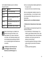
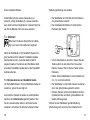
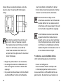
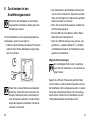
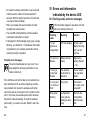
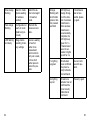
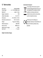
1
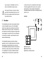
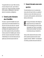
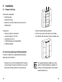
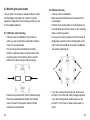
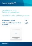
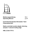
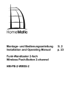
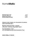
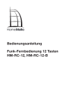
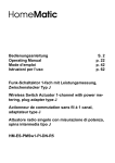
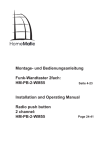
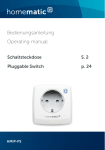
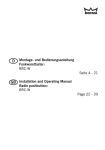
Montage- und Bedienungsanleitung (S. 2)
Installation and operating manual
(p. 35)
Funk-Wandtaster 6-fach
Wireless Push Button 6 channel
HM-PB-6-WM55
Inhaltsverzeichnis
1. Ausgabe Deutsch, 02/2013
Dokumentation © 2013 eQ-3 AG, Deutschland
Alle Rechte vorbehalten. Ohne schriftliche
Zustimmung des Herausgebers darf dieses
Handbuch auch nicht auszugsweise in irgendeiner
Form reproduziert werden oder unter Verwendung
elektronischer, mechanischer oder chemischer
Verfahren vervielfältigt oder verarbeitet werden.
Es ist möglich, dass das vorliegende Handbuch noch
drucktechnische Mängel oder Druckfehler aufweist.
Die Angaben in diesem Handbuch werden jedoch
regelmäßig überprüft und Korrekturen in der nächsten
Ausgabe vorgenommen. Für Fehler technischer oder
drucktechnischer Art und ihre Folgen übernehmen wir
keine Haftung.
Alle Warenzeichen und Schutzrechte werden anerkannt.
Printed in Hong Kong
Änderungen im Sinne des technischen Fortschritts
können ohne Vorankündigung vorgenommen werden.
130104/V 1.4
2
1
Hinweise zu dieser Anleitung . . . . . . . . . . . . . . 4
2Gefahrenhinweise . . . . . . . . . . . . . . . . . . . . . . . 4
3Funktion . . . . . . . . . . . . . . . . . . . . . . . . . . . . . . 5
4
Allgemeine Systeminformation zu HomeMatic . 7
5
Allgemeine Hinweise zum
Funkbetrieb . . . . . . . . . . . . . . . . . . . . . . . . . . . . 8
6Montage . . . . . . . . . . . . . . . . . . . . . . . . . . . . . . 9
6.1Lieferumfang . . . . . . . . . . . . . . . . . . . . . . . . . . . 9
6.2 Beschriftungsvorlage einlegen/wechseln . . . . . 9
6.3 Wandtaster montieren . . . . . . . . . . . . . . . . . . . 11
6.4 Montage in Mehrfachkombinationen . . . . . . . . 13
7Inbetriebnahme . . . . . . . . . . . . . . . . . . . . . . . . 16
7.1 Batterien einlegen (wechseln) . . . . . . . . . . . . . 16
7.2 Verhalten nach Batteriewechsel . . . . . . . . . . . 17
7.3Anlernen . . . . . . . . . . . . . . . . . . . . . . . . . . . . . 18
8Bedienung . . . . . . . . . . . . . . . . . . . . . . . . . . . . 25
9
Zurücksetzen in den Auslieferungszustand . . . 26
10 Fehler- und Rückmeldungen durch die GeräteLED . . . . . . . . . . . . . . . . . . . . . . . . . . . . . . . . . 28
10.1 Blinkcodes und Fehlermeldungen . . . . . . . . . . 28
10.2 Befehl nicht bestätigt . . . . . . . . . . . . . . . . . . . . 31
10.3 Duty Cycle überschritten . . . . . . . . . . . . . . . . . 31
11
Wartung und Reinigung . . . . . . . . . . . . . . . . . . 32
12 Technische Eigenschaften . . . . . . . . . . . . . . . 33
3
1 Hinweise zu dieser Anleitung
Lesen Sie diese Anleitung sorgfältig, bevor Sie Ihre
HomeMatic Komponenten in Betrieb nehmen.
Bewahren Sie die Anleitung zum späteren Nachschlagen auf! Wenn Sie das Gerät anderen Personen
zur Nutzung überlassen, übergeben Sie auch diese
Bedienungsanleitung.
Benutzte Symbole:
Achtung! Hier wird auf eine Gefahr hingewiesen.
Hinweis! Dieser Abschnitt enthält zusätzliche
wichtige Informationen!
2Gefahrenhinweise
Betreiben Sie das Gerät nur in Innenräumen
und vermeiden Sie den Einfluss von
Feuchtigkeit, Staub sowie Sonnen- oder
andere Wärmebestrahlung. Jeder andere
Einsatz als der in dieser Bedienungsanleitung
beschriebene ist nicht bestimmungsgemäß
und führt zu Garantie- und Haftungsausschluss. Dies gilt auch für Umbauten und
4
Veränderungen. Die Geräte sind ausschließlich für den privaten Gebrauch gedacht.
Öffnen Sie das Gerät nicht, es enthält keine
durch den Anwender zu wartenden Teile. Im
Fehlerfall schicken Sie das Gerät an den
Service.
3Funktion
Der HomeMatic Wandtaster kann direkt an andere
HomeMatic Geräte oder die HomeMatic Zentrale
angelernt werden, um z. B. Beleuchtung ein- bzw.
auszuschalten und Rollladen rauf bzw. runter zu
fahren. Die Funktionen der 6 Tasten können frei
gewählt werden. An eine Taste können dabei mehrere
Geräte angelernt werden. Dadurch können über einen
einzigen Tastendruck gleichzeitig mehrere Funktionen
ausgeführt werden.
Der HomeMatic Wandtaster ist batteriebetrieben
und bietet deshalb eine hohe Flexibilität bei der
Montage und Wahl des Montageortes. Installation
und Demontage gestalten sich durch Schrauben
oder Kleben auf unterschiedlichen Untergründen wie
Mauerwerk, Möbeln, Fliesen oder Glas sehr einfach.
5
Ein Stemmen oder Schlitzen von Mauerwerk ist nicht
erforderlich. Die Wandmontage kann im mitgelieferten
Rahmen erfolgen. Zusätzlich ist es auch möglich, den
HomeMatic Wandtaster in bestehende Schalterserien
zu integrieren (siehe Abschnitt 6.4).
Die nebeneinander liegenden Tasten bilden jeweils ein
Tastenpaar, das beim direkten Verknüpfen mit einem
Aktor gemeinsam angelernt wird. Die jeweils linke
Taste hat dabei die Funktion „Aus/Dunkler/Runter“ und
die rechte Taste „An/Heller/Hoch“.
Bedienelemente:
4 Allgemeine Systeminformation
zu HomeMatic
A
B
C
Dieses Gerät ist Teil des HomeMatic Haussteuersystems und arbeitet mit dem bidirektionalen BidCoS®
Funkprotokoll.
Alle Geräte werden mit einer Standardkonfiguration
ausgeliefert. Darüber hinaus ist die Funktion des
Gerätes über ein Programmiergerät und Software
konfigurierbar. Welcher weitergehende Funktionsumfang sich damit ergibt, und welche Zusatzfunktionen
sich im HomeMatic System im Zusammenspiel mit
weiteren Komponenten ergeben, entnehmen Sie bitte
dem HomeMatic WebUI Handbuch.
Alle technischen Dokumente und Updates finden Sie
stets aktuell unter www.homematic.com.
(A) Montageplatte
(B) Wechselrahmen
(C) Elektronikeinheit/Taster
6
7
5 Allgemeine Hinweise zum
Funkbetrieb
6Montage
Die Funk-Übertragung wird auf einem nicht exklusiven
Übertragungsweg realisiert, weshalb Störungen nicht
ausgeschlossen werden können. Weitere Störeinflüsse
können u.a. durch Schaltvorgänge, Elektromotoren
oder auch defekte Elektrogeräte hervorgerufen
werden.
Wandtaster zusammengebaut:
• Montageplatte
• Wechselrahmen
• Elektronikeinheit mit 6 Tasten und Abdeckung für
das Schriftfeld
Die Reichweite in Gebäuden kann stark von
der im Freifeld abweichen. Außer der
Sendeleistung und den Empfangseigenschaften der Empfänger spielen Umwelteinflüsse
wie Luftfeuchtigkeit neben baulichen
Gegebenheiten vor Ort eine wichtige Rolle.
Hiermit erklärt die eQ-3 AG, dass sich dieses Gerät in
Übereinstimmung mit den grundlegenden Anforderungen und den anderen relevanten Vorschriften der
Richtlinie 1999/5/EG befindet.
Die vollständige Konformitätserklärung finden Sie
unter www.homematic.com.
8
6.1Lieferumfang
Zubehör
• Klebestreifen zur Wandmontage
• 2 Stück Holzschrauben 3,0 x 30 mm
• 2 Stück Dübel 5 mm
• 2 LR03-Batterien (Micro/AAA/LR03)
• Beschriftungsvorlagen
6.2 Beschriftungsvorlage einlegen/
wechseln
Um die beiliegende Beschriftungsvorlage einzulegen
bzw. zu wechseln, gehen Sie wie folgt vor:
• Entfernen Sie die Abdeckung für das Schriftfeld,
indem Sie von oben mit zwei Fingern hinter die
Abdeckung greifen und diese nach vorne von der
Elektronikeinheit abziehen (siehe Pfeile).
9
6.3 Wandtaster montieren
ON
ON
ON
• Legen Sie die gewünschte Beschriftungsvorlage ein.
• Setzen Sie die Abdeckung wieder auf die Elektronikeinheit auf. Achten Sie darauf, dass die Rastnasen in die dafür vorgesehenen Löcher einrasten.
ON
ON
ON
OFF
OFF
OFF
Sie können den HomeMatic Wandtaster entweder an
eine Wand schrauben oder kleben. Der Wandtaster
lässt sich bequem in den mitgelieferten Rahmen
oder in eine bestehende Schalterserie (Auflistung
der kompatiblen Schalterserien siehe Abschnitt 6.4)
integrieren.
6.3.1Klebestreifen-Montage
• Wählen Sie einen beliebigen Ort zur Befestigung
aus. Der Untergrund muss sauber, trocken und
fettfrei sein.
• Bringen Sie den Wandtaster im zusammengebauten Zustand an. Hierzu befestigen Sie die
Klebestreifen auf der Rückseite der Montageplatte. Achten Sie darauf, dass die Schrift auf der
Rückseite für Sie lesbar ist.
OFF
OFF
Die beigefügte Beschriftungsvorlage sowie
eine Vorlage für individuelle Beschriftungen
zum finden Sie zum Ausdrucken im DownloadBereich der Webseite www.homematic.com.
10
OFF
<PA66>
11
• Entfernen Sie die Folie von den Klebestreifen.
• Drücken Sie jetzt den zusammengebauten
Wandtaster mit der Rückseite an die gewünschte
Position an die Wand.
6.3.2Schraub-Montage
• Wählen Sie einen geeigneten Montageort aus.
• Stellen Sie sicher, dass in der Wand keine Leitungen verlaufen.
• Halten Sie die Montageplatte an die gewünschte
Montageposition. Achten Sie darauf, dass der Pfeil
auf der Vorderseite der Montageplatte nach oben
zeigt.
• Zeichnen Sie zwei der Bohrlöcher A anhand der
Montageplatte (diagonal gegenüberliegend) mit
einem Stift an der Wand an. Die Bohrlöcher B
können für die Montage auf einer Unterputzdose
verwendet werden.
B
A
12
B
B
B
A
• Bohren Sie die vorgezeichneten Löcher. Bei
Steinwänden verwenden Sie einen 5 mm Bohrer
für die Dübel. (Bei Holzwänden können Sie einen
1,5 mm Bohrer verwenden, um das Eindrehen der
Schrauben zu erleichtern.)
• Montieren Sie die Montageplatte durch Eindrehen
der mitgelieferten Schrauben und Dübel.
• Positionieren Sie nun den Wechselrahmen auf der
Montageplatte und setzen Sie den Taster ein.
• Achten Sie darauf, dass die Pfeile auf der Rückseite der Elektronikeinheit nach oben zeigen und
die Klammern der Montageplatte in die Öffnungen
der Elektronikeinheit rasten.
6.4 Montage in Mehrfachkombinationen
Sie können den Wandtaster sowohl mit dem mitgelieferten Rahmen, als auch mit Rahmen anderer
Hersteller verwenden oder die Elektronikeinheit in
einen Mehrfachrahmen integrieren. In beiden Fällen ist
sowohl eine Klebestreifen-, als auch eine SchraubMontage möglich. Bei der Montage in Mehrfachkombinationen ist darauf zu achten, dass die Montageplatte
des Wandtasters bündig neben bereits befestigte
Montageplatten/Tragringe angebracht und daran
ausgerichtet wird.
13
Der HomeMatic Wandtaster passt in die Rahmen
folgender Hersteller:
Hersteller
Rahmen
Berker
S.1, B.1, B.3, B.7 Glas
ELSO
Joy
GIRA
System 55, Standard 55, E2, E22,
Event, Esprit
merten
1-M, Atelier-M, M-Smart, M-Arc, MStar, M-Plan
JUNG
A 500, AS 500, A plus, A creation
Sollten für die Montage bzw. Installation des
Gerätes Änderungen oder Arbeiten an der
Hausinstallation (z.B. Ausbau, Überbrücken
von Schalter- oder Steckdoseneinsätzen) oder
an der Niederspannungsverteilung erforderlich
sein, ist unbedingt folgender Sicherheitshinweis
zu beachten:
Installation nur durch Personen mit
einschlägigen elektrotechnischen
Kenntnissen und Erfahrungen! (*1)
14
Durch eine unsachgemäße Installation gefährden Sie
• Ihr eigenes Leben;
• das Leben der Nutzer der elektrischen Anlage.
Mit einer unsachgemäßen Installation riskieren Sie
schwere Sachschäden, z. B. durch Brand. Es droht
für Sie die persönliche Haftung bei Personen- und
Sachschäden.
Wenden Sie sich an einen Elektroinstallateur!
(*1) Erforderliche Fachkenntnisse für die Installation
Für die Installation sind insbesondere folgende Fachkenntnisse erforderlich:
• die anzuwendenden ‚5 Sicherheitsregeln‘: Freischalten; gegen Wiedereinschalten sichern; Spannungsfreiheit feststellen; Erden und Kurzschließen;
benachbarte, unter Spannung stehende Teile
abdecken oder abschranken;
• Auswahl des geeigneten Werkzeuges, der Messgeräte und ggf. der persönlichen Schutzausrüstung;
• Auswertung der Messergebnisse;
15
• Auswahl des Elektro-Installationsmaterials zur Sicherstellung der Abschaltbedingungen;
• IP-Schutzarten;
• Einbau des Elektroinstallationsmaterials;
• Art des Versorgungsnetzes (TN-System, ITSystem, TT-System) und die daraus folgenden Anschlussbedingungen (klassische Nullung, Schutzerdung, erforderliche Zusatzmaßnahmen etc.).
7Inbetriebnahme
7.1 Batterien einlegen (wechseln)
• In montiertem Zustand lässt sich der Taster einfach aus dem Rahmen und von der Montageplatte
ziehen. Fassen Sie den Taster seitlich an und ziehen sie ihn aus dem Rahmen heraus. Ein weiteres
Öffnen des Gerätes ist nicht erforderlich.
• Drehen Sie den Taster auf die Rückseite, um die
Batterien einzulegen bzw. sie zu entnehmen.
• Nach Entnahme der Batterien sollten ca. 10
Sekunden gewartet werden.
• Legen Sie zwei LR03 Batterien (Micro/AAA)
polungsrichtig gemäß Markierung in die Batteriefächer ein.
• Setzen Sie den Taster wieder in den Rahmen.
16
Normale Batterien dürfen niemals aufgeladen
werden. Batterien nicht ins Feuer werfen!
Batterien nicht kurzschließen! Es besteht
Explosionsgefahr!
Verbrauchte Batterien gehören nicht in
den Hausmüll! Entsorgen Sie diese in
Ihrer örtlichen Batteriesammelstelle!
7.2 Verhalten nach Batteriewechsel
Nach dem Einlegen der Batterie führt der Wandtaster
zunächst einen Selbsttest/Neustart (ca. 2 Sekunden)
durch. Die LED blinkt kurz rot, grün, orange auf (LEDTest-Anzeige). Danach erfolgt die Initialisierung.
Bei niedriger Batteriespannung wird, sofern es
der Spannungswert noch zulässt, trotzdem die
Tastenabfrage aktiviert und der Wandtaster ist
betriebsbereit. Je nach Beanspruchung kann
evtl. nach kurzer Ruhezeit der Batterie wieder
mehrfach gesendet werden.
Wenn Sie schwache Batterien verwenden, kann
das Gerät beim Betätigen einer Taste automatisch einen Neustart durchführen. Dann blinkt
die Geräte-LED kurz rot, grün, orange,
gefolgt von 5 x kurzem roten Blinken
17
für die schwache Batterie.
Ist die Batterie für die weitere Verwendung zu
schwach, erfolgt die Meldung (5 x kurzes rotes Blinken) direkt nach dem Tastendruck. In diesem Fall müssen Sie die Batterie durch eine neue ersetzen.
Bedienungsanleitung des Gerätes.
• Der Wandtaster wird mit Hilfe der Anlerntaste in
den Anlernmodus versetzt.
• Die Anlerntaste A befindet sich direkt auf der
Rückseite des Tasters.
7.3Anlernen
Bitte lesen Sie diesen Abschnitt erst vollständig, bevor sie mit dem Anlernen beginnen!
Damit der Wandtaster in Ihr HomeMatic System integriert werden und mit anderen HomeMatic-Geräten
kommunizieren kann, muss das Gerät zunächst
angelernt werden. Sie können den Wandtaster direkt
an andere HomeMatic-Geräte oder an die HomeMatic
Zentrale anlernen.
7.3.1Direktes Anlernen an HomeMatic Geräte
Um HomeMatic Aktoren mit dem Wandtaster bedienen
zu können, gehen Sie wie folgt vor:
Zum Anlernen müssen die beiden zu verknüpfenden
Geräte in den Anlernmodus gebracht werden. Wie
Sie den anzulernenden Aktor in den Anlernmodus
versetzen, entnehmen Sie bitte der entsprechenden
18
A
• Um die Anlerntaste zu erreichen, fassen Sie den
Taster seitlich an und ziehen Sie ihn aus dem
Rahmen heraus. Drehen Sie den Taster auf die
Rückseite.
• Halten Sie den Wandtaster in einem Abstand von
min. 1 m vom Aktor entfernt.
• Der Wandtaster und der Aktor müssen nacheinander in den Anlernmodus gebracht werden:
• Drücken Sie kurz auf die Anlerntaste A. Der Konfigurationsmodus wird durch grünes Blinken der
Geräte-LED angezeigt.
Drehen Sie den Wandtaster gemäß Abbildung
(Pfeilrichtung nach oben) auf die Vorderseite und
19
drücken Sie kurz eine der Bedientasten, an die Sie
anlernen wollen. Die Geräte-LED blinkt langsam
orange.
sten für den Befehl „An/Heller/Hoch“ definiert.
• Sofern Sie den Anlernmodus abbrechen möchten,
drücken Sie nochmals kurz die Anlerntaste.
Wenn kein Anlernen erfolgt, wird der
Anlernmodus automatisch nach 20 Sekunden
beendet. Befindet sich ein anderes Gerät im
Anlernmodus, wird dieses angelernt. Dies wird
durch schnelles oranges Blinken angezeigt.
Beim Anlernen werden immer eine linke und
eine rechte Taste als Tastenpaar angelernt.
Dies bedeutet, dass beim Drücken einer linken
Taste z. B. die Funktion „Aus“ und für die
rechte Taste automatisch die Funktion „Ein“
angelernt wird. Dies gilt ebenso für die anderen
beiden Tastenpaare.
• Bringen Sie jetzt den Aktor in den Anlernmodus.
• Das erfolgreiche Anlernen der Bedientaste wird
durch kurzes grünes Leuchten der Geräte-LED
angezeigt.
• Die jeweils linken Bedientasten sind für den Befehl
„Aus/Dunkler/Runter“ und die rechten Bedienta20
Ist der Wandtaster bereits an eine Zentrale
angelernt und damit für direktes Anlernen
gesperrt, kann er zwar wie oben beschrieben
in den Konfigurationsmodus gebracht werden,
nach Drücken einer Bedientaste leuchtet die
Geräte-LED jedoch für 2 Sekunden rot auf. Es
ist kein direktes Anlernen möglich.
7.3.2Anlernen an eine HomeMatic Zentrale
Um Ihr Gerät softwarebasiert und komfortabel
• steuern und konfigurieren,
• direkt mit anderen Geräten verknüpfen oder
• in Zentralenprogrammen nutzen zu können,
muss es zunächst an die HomeMatic Zentrale angelernt werden. Das Anlernen neuer Geräte an die
21
Zentrale erfolgt über die HomeMatic Bedienoberfläche
„WebUI“.
Sobald eine Komponente an eine Zentrale angelernt ist, kann sie nur noch über diese mit
anderen Komponenten verknüpft werden.
Jede Komponente kann immer nur an eine
Zentrale angelernt werden.
Beim Anlernen beachten Sie bitte, dass Sie
einen Abstand der Geräte zur Zentrale von
mindestens 50 cm einhalten.
Zum Anlernen Ihres Gerätes an die Zentrale gehen Sie
wie folgt vor:
• Öffnen Sie die WebUI-Bedienoberfläche in Ihrem
Browser. Klicken Sie auf den Button „Geräte anlernen“ im rechten Bildschirmbereich. Der Anlernmodus wird automatisch gestartet.
• Der Anlernmodus ist für 60 Sekunden aktiv. Das Infofeld zeigt die aktuell noch verbleibende Anlernzeit.
• Versetzen Sie innerhalb dieser Anlernzeit auch den
HomeMatic Wandtaster in den Konfigurationsmodus.
• Drücken Sie kurz auf die Anlerntaste des Wandtasters. Der Wandtaster befindet sich nun im Konfi22
gurationsmodus. Dies wird durch grünes Blinken
der Geräte-LED angezeigt.
• Nach kurzer Zeit erscheint das neu angelernte Gerät
im Posteingang Ihrer Softwareoberfläche. Der Button „Posteingang (x neue Geräte)“ zeigt dabei an,
wie viele neue Geräte erfolgreich angelernt wurden.
• Lernen Sie ggf. weitere Geräte an, indem Sie die
vorher beschriebenen Schritte für jedes Gerät
wiederholen.
• Konfigurieren Sie nun die neu angelernten Geräte
im Posteingang wie im folgenden Abschnitt („Neu
angelernte Geräte konfigurieren“) beschrieben.
Neu angelernte Geräte konfigurieren:
Nachdem Sie Ihr Gerät an die HomeMatic Zentrale
angelernt haben, wird es in den „Posteingang“ verschoben. Hier muss Ihr Gerät und die dazugehörigen
Kanäle zunächst konfiguriert werden, damit es für Bedien- und Konfigurationsaufgaben zur Verfügung steht.
Vergeben Sie einen Namen und ordnen Sie das Gerät
einem Raum zu. Sie haben zusätzlich die Möglichkeit,
einzelne Parametereinstellungen vorzunehmen.
Anschließend können Sie Ihr Gerät über die Bedienoberfläche „WebUI“ steuern und konfigurieren, direkt
mit anderen Geräten verknüpfen oder in Zentralenprogrammen nutzen. Einzelheiten hierzu entnehmen Sie
23
bitte der WebUI Bedienungsanleitung (zu finden im
Download-Bereich der Website www.HomeMatic.com).
Übersicht Blinkcodes während des Anlernvorgangs:
LED Blinkcodes
Bedeutung
1 s grüne LED
Anlernen erfolgreich.
2 s rote LED
Anlernen fehlgeschlagen.
Versuchen Sie es erneut.
Langsames orangenes
Blinken
Es befindet sich nur der
Wandtaster im Anlernmodus. Bringen Sie das
anzulernende Gerät ebenfalls in den Anlernmodus.
Schnelles oranges
Blinken gefolgt von 1 s
grünes oder 2 s rotes
Leuchten (je nach
Erfolg)
Beide Geräte befinden
sich im Anlernmodus, Anlernvorgang läuft.
Wandtaster im Konfigurationsmodus
(langsames grünes
Blinken) und bei Tastenbetätigung rotes
Aufleuchten
Wandtaster bereits an
Zentrale angelernt und
damit gegen direktes Anlernen gesperrt (siehe Abschnitt „Direktes Anlernen
an HomeMatic Geräte“).
24
8Bedienung
Die 6 Tasten sind im Auslieferungszustand als drei
separate Tastenpaare (TP 1, TP 2 und TP 3) definiert.
Dabei hat die jeweils rechte Taste die Funktion „An/
Heller/Hoch“ und die linke Taste „Aus/Dunkler/Runter“.
Mit dem HomeMatic Wandtaster können Sie
• Licht an- bzw. ausschalten (TP 1)
• Licht heller bzw. dunkler dimmen (TP 2) und
• Rollladen hoch- bzw. runterfahren (TP 3).
TP 1
Aus
Licht
An
TP 2
Dunkler
Dimmer
Heller
TP 3
Runter
Rollladen
Hoch
25
9 Zurücksetzen in den
Auslieferungszustand
Sie können den Wandtaster in den Auslieferungszustand zurücksetzen. Dabei gehen alle
Einstellungen verloren.
Um den Wandtaster in den Auslieferungszustand zurückzusetzen, gehen Sie wie folgt vor:
• Halten Sie die Anlerntaste mindestens 5 Sekunden
gedrückt. Die LED des Wandtasters beginnt langsam rot zu blinken.
5s
A
Wollen Sie an dieser Stelle das Zurücksetzen
abbrechen, können Sie das mit einem kurzen
erneuten Tastendruck auf die Anlerntaste tun
oder 20 Sekunden abwarten. In beiden Fällen
stoppt das langsame rote Blinken und das Zurücksetzen ist beendet.
26
• Zum Zurücksetzen des Wandtasters drücken Sie
nun erneut für mindestens 5 Sekunden die Anlerntaste. Die LED beginnt nun während des gedrückt
Haltens schneller rot zu blinken.
• Wenn Sie die Anlerntaste loslassen, schließt dies
den Rücksetzvorgang ab.
• Die rote LED hört auf zu Blinken und der Wandtaster führt einen Neustart durch.
• Nach der LED-Test-Anzeige (rotes, grünes, oranges Blinken - vergleiche Kapitel 6.1.3 „Verhalten
nach Batteriewechsel) ist der Wandtaster zurückgesetzt und einsatzbereit.
Mögliche Fehlermeldungen:
Der nachfolgende Fehler kann nur auftreten,
wenn Sie den Wandtaster an eine Zentrale angelernt haben.
Beginnt die LED nach 5 Sekunden gedrückt Halten
nicht zu blinken, sondern leuchtet dauerhaft auf, kann
der Wandtaster nicht zurückgesetzt werden. In diesem
Fall ist das manuelle Zurücksetzen für das Gerät gesperrt worden. Setzen Sie den Wandtaster über die
Konfigurationssoftware der Zentrale zurück.
27
10 Fehler- und Rückmeldungen
durch die Geräte-LED
10.1Blinkcodes und Fehlermeldungen
Die Rückmeldungen gelten sowohl für den Betrieb mit als auch ohne Zentrale.
Blinkcode
Bedeutung
Lösung
1 x rotes,
grünes und
oranges
Blinken
LED-TestAnzeige
Nachdem die
Test-Anzeige
erloschen ist,
können Sie fortfahren.
5 x kurzes
rotes Blinken
Batterie fast leer
Tauschen Sie
die Batterie aus
(Kapitel 7.1.2).
1 x langes,
2 x kurzes
rotes Blinken
Der Wandtaster
ist defekt.
Bitte wenden
Sie sich an Ihren
Fachhändler.
1 x langes
und 1 x
kurzes rotes
Blinken
Duty Cycle
Siehe Kapitel
10.3 „Duty Cycle
überschritten“.
28
Langsames
grünes
Blinkes
Konfigurationsmodus (Gerät
wartet auf Funk)
Warten bis Konfigurationsdaten
gesendet wurde.
Langsames
oranges
Blinken
Anlernmodus
(Gerät wartet
auf Funkpartner)
Bringen Sie das
anzulernende
Gerät in den Anlernmodus.
Schnelles
oranges
Blinken
Konfigurations- oder
Anlernmodus
(Daten werden
empfangen)
Warten Sie, bis
der Vorgang beendet ist.
LED blinkt
langsam rot
Vorstufe zum
Zurücksetzen auf die
Werkseinstellungen
Gerät wartet
auf langen Tastendruck der
Anlerntaste zum
Zurücksetzen
oder kurzen Tastendruck zum
Beenden.
29
Oranges
Blinken bei
kurzem bzw.
langem
Tastendruck
1 s grünes
Leuchten
2 s rotes
Leuchten
30
Die LED leuchtet solange
orange, wie
die Funkübertragung
andauert. Nach
erfolgreicher
Funkübertragung leuchtet
die LED für
1 s grün, bei
fehlerhafter
Übertragung für
2 s rot auf.
Bei fehlerhafter
Übertragung
versuchen es
Sie bitte erneut.
Alle Aktoren
haben den
(letzten) bidirektionalen Befehl
bestätigt.
Sie können mit
der weiteren
Bedienung fortfahren.
Mindestens ein
Aktor hat den
(letzten) bidirektionalen Befehl
nicht bestätigt.
Bitte versuchen
Sie es erneut.
10.2Befehl nicht bestätigt
Bestätigt ein Empfänger (bei mehreren angelernten
Geräten, mindestens einer) einen Befehl nicht, leuchtet zum Abschluss der Übertragung die Geräte-LED rot
auf. Dieses Verhalten kann folgende Ursachen haben:
• Der Empfänger ist nicht erreichbar.
• Der Empfänger kann den Befehl nicht ausführen
(Lastausfall, mechanische Blockade etc.).
• Der Empfänger ist defekt.
10.3Duty Cycle überschritten
Der Duty Cycle beschreibt eine gesetzlich geregelte
Begrenzung der Sendezeit von Geräten im 868 MHz
Bereich. Das Ziel dieser Regelung ist es, die Funktion
aller im 868 MHz Bereich arbeitenden Geräte zu gewährleisten.
In dem von uns genutzten Frequenzbereich 868 MHz
beträgt die maximale Sendezeit eines jeden Gerätes
1 % einer Stunde (also 36 Sekunden in einer Stunde).
Die Geräte dürfen bei Erreichen des 1 %- Limits nicht
mehr senden, bis diese zeitliche Begrenzung vorüber
ist. Gemäß dieser Richtlinie, werden HomeMatic- Geräte zu 100 % normenkonform entwickelt und produziert.
31
Im normalen Betrieb wird der Duty Cycle in der Regel
nicht erreicht. Dies kann jedoch in Einzelfällen bei der
Inbetriebnahme oder Erstinstallation eines Systems
durch vermehrte und funkintensive Anlernprozesse der
Fall sein. Eine Überschreitung des Duty Cylcle Limits
wird durch einmal langes und einmal kurzes rotes Blinken der Geräte LED angezeigt und kann sich durch
temporär fehlende Funktion des Gerätes äußern. Nach
kurzer Zeit (max. 1 Stunde) ist die Funktion des Gerätes wiederhergestellt.
11 Wartung und Reinigung
Das Produkt ist für Sie bis auf einen eventuell erforderlichen Batteriewechsel wartungsfrei. Überlassen
Sie eine Wartung oder Reparatur einer Fachkraft. Reinigen Sie das Produkt mit einem weichen, sauberen,
trockenen und fusselfreien Tuch. Für die Entfernung
von stärkeren Verschmutzungen kann das Tuch leicht
mit lauwarmem Wasser angefeuchtet werden. Verwenden Sie keine lösemittelhaltigen Reinigungsmittel,
das Kunststoffgehäuse und die Beschriftung können
dadurch angegriffen werden.
32
12 Technische Eigenschaften
Kurzbezeichnung: . . . . . . . . . . . . . . . . HM-PB-6-WM55
Versorgungsspannung: . . . .2 x 1,5 V LR03/Micro AAA
Batterielebensdauer: . . . . . . . . . . . . . . . . . ca. 5 Jahre
Schutzart: . . . . . . . . . . . . . . . . . . . . . . . . . . . . . . . IP20
Umgebungstemperatur . . . . . . . . . . . . . -10 bis +55 °C
Abmessungen: . . . . . . . . . . . . . 85,5 x 85,5 x 21,5 mm
Abmessungen Tastereinheit: . . . . . . . 55 x 55 x 20 mm
Gewicht: . . . . . . . . . . . . . . . . . . . 70 g (ohne Batterien)
Funkfrequenz: . . . . . . . . . . . . . . . . . . . . . . . 868,3 MHz
Empfängerklasse . . . . . . . . . . . . . . . . . . . SRD Class 2
Typ. Funk-Freifeldreichweite: . . . . . . . . . . . . . > 100 m
Duty Cycle: . . . . . . . . . . . . . . . . . . . . . . . . < 1 % pro h
Technische Änderungen sind vorbehalten.
33
Entsorgungshinweis
Gerät nicht im Hausmüll entsorgen!
Elektronische Geräte sind entsprechend
der Richtlinie über Elektro- und ElektronikAltgeräte über die örtlichen Sammelstellen
für Elektronik-Altgeräte zu entsorgen.
Das CE-Zeichen ist ein Freiverkehrszeichen, das sich ausschließlich an die
Behörden wendet und keine Zusicherung
von Eigenschaften beinhaltet
1. English edition 02/2013
Documentation © 2013 eQ-3 AG, Germany
All rights reserved. No parts of this manual may be
reproduced or processed in any form using electronic,
mechanical or chemical processes in part or in full
without the prior explicit written permission of the
publisher.
It is quite possible that this manual has printing
errors or defects. The details provided in this manual
are checked regularly and corrections are done in the
next edition. We do not assume any liability for technical or printing errors.
All registered trade marks and copyrights are
acknowledged.
Printed in Hong Kong
We reserve the right to make changes due to technical
advancements without prior notice.
130104/V 1.4
34
35
Table of Contents
1 Information about this manual
1
Information about this manual . . . . . . . . . . . . 37
2
Hazard information . . . . . . . . . . . . . . . . . . . . . 37
3Function . . . . . . . . . . . . . . . . . . . . . . . . . . . . . 38
4
General system information
about HomeMatic . . . . . . . . . . . . . . . . . . . . . . 40
5
General information about radio operation . . . 41
6Installation . . . . . . . . . . . . . . . . . . . . . . . . . . . . 42
6.1 Scope of delivery . . . . . . . . . . . . . . . . . . . . . . . 42
6.2 Beschriftungsvorlage einlegen/wechseln . . . . 42
6.3 Mounting the push button . . . . . . . . . . . . . . . . 44
6.4 Installation in multiple combinations . . . . . . . . 46
7
Start up . . . . . . . . . . . . . . . . . . . . . . . . . . . . . . 49
7.1 Inserting (changing) batteries . . . . . . . . . . . . . 49
7.2 Behaviour after replacing batteries . . . . . . . . 50
7.3 Teaching in . . . . . . . . . . . . . . . . . . . . . . . . . . . 51
8Operation . . . . . . . . . . . . . . . . . . . . . . . . . . . . 58
9
Resetting to the as-delivered condition . . . . . . 59
10 Errors and information indicated by the device
LED . . . . . . . . . . . . . . . . . . . . . . . . . . . . . . . . . 61
10.1 Flashing codes and error messages . . . . . . . . 61
10.2 Command not confirmed . . . . . . . . . . . . . . . . . 64
10.3 Duty cycle exceeded . . . . . . . . . . . . . . . . . . . . 64
11
Maintenance and cleaning . . . . . . . . . . . . . . . 65
12 Technical data . . . . . . . . . . . . . . . . . . . . . . . . . 66
Read this manual carefully before beginning operation
with your HomeMatic components. Keep the manual
handy for later consultation! Please hand-over the
operating manual as well when you hand-over the device to other persons for use.
36
Symbols used:
Attention! This indicates a hazard.
Note. This section contains additional important
information!
2 Hazard information
This device is to be operated indoors only and
keep away from the influences of humidity,
dust and sunshine or other radiating heat
sources. Using the push button for any
purpose other than that described in this
operating manual does not fall within the
scope of intended use and shall invalidate
any warranty or liability. This also applies to
37
any conversion or modification work. This
device is intended for private use only.
Do not open the device. It does not contain
any parts to be maintained by the user. If an
error occurs, please send back the device to
the customer service.
or slits do not have to be chiselled out of brick walls.
The frame supplied with the device can be used for
wall mounting. It is also possible to integrate the
HomeMatic wireless push button into existing switches
(see sec. 6.4).
Controls:
A
3Function
The HomeMatic push button can be taught-in directly
to other HomeMatic devices or to the HomeMatic
central. Thus, lights can be switched on and off and
shutters can be moved up or down. The functions of
the 6 buttons can be freely configured. A single button
can be taught-in to work with one or more components. At the push of a button, several functions can be
executed simultaneously.
The HomeMatic wireless push button is batteryoperated. As such it is highly flexible where mounting
and selecting a mounting location are concerned.
The HomeMatic wireless push button is mounted and
removed very easily using screws or adhesive strips.
It is compatible with a number of different surfaces
including furniture, brick walls, tiles or glass. Holes
38
B
C
(A) Mounting plate
(B) Attachment frame
(C) Electronic unit/rocker button
39
The opposite buttons serve as pair. When connecting
the device directly with an actor, a pair of buttons is
taught-in at once. Thereby, the left buttons are defined
for the instructions „Off/Darker/Down“ and the right
buttons for the instructions „On/Brighter/Up“.
4 General system information
about HomeMatic
This device is a part of the HomeMatic home control
system and works with the bidirectional BidCoS wireless protocol. All devices are delivered in a standard
configuration. The functionality of the device can also
be configured with a programming device and software. Further resulting functionality and the additional
functions provided in the HomeMatic system combined
with other components are described in the HomeMatic WebUI Manual. All current technical documents and
updates are provided under www.homematic.com.
®
40
5 General information about radio
operation
The radio transmission is on a non-exclusive transmission path which means that there is a possibility of
interference occurring. Other interfering sources can
be caused by switching operations, electrical motors or
defective electrical devices.
The range of transmission within buildings can
greatly deviate from open air distances. Besides the transmitting power and the reception
characteristics of the receiver, environmental
influences such as humidity in the vicinity and
local structures also play an important role.
Hereby eQ-3 AG, declares that this device conforms
with the essential requirements and other relevant
regulations of Directive 1999/5/EC. The full declaration
of conformity is provided under www.homematic.com.
41
6Installation
6.1 Scope of delivery
Push button assembled:
• Mounting plate
• Attachment frame
• Electronic unit with 6 buttons and cover for the
labelling field
Accessories:
• Adhesive strips for wall mount
• 2 wood screws 3.0 x 30 mm
• 2 wall anchors 5 mm
• 2 LR03 batteries (micro/AAA/LR03)
• Labelling template
ON
ON
ON
• Insert the desired labelling template.
• Put the cover back to the electronic unit. Make
sure that the latch will snap into the provided holes.
ON
ON
6.2 Inserting (replacing) labelling template
To insert or replace the supplied labelling template,
please proceed as follows:
• Remove the cover for the labelling field. Therefore,
put two fingers from above behind the cover, pull it
forward and off the electronic unit (see arrows).
42
ON
OFF
OFF
OFF
The supplied labelling template and a template for individual labelling is available for
printing in the download area of the website
www.homematic.com.
43
OFF
OFF
OFF
6.3 Mounting the push button
You can either use screws or adhesive strips to mount
the HomeMatic push button to a wall in the frame
supplied or integrate it into an existing switch (see sec.
6.4 for suitable switches).
6.3.1Adhesive strip mounting
• Choose a site for installation. The surface on
which you are mounting the push button must be
clean, dry and greaseless.
• For mounting of the assembled push button,
attach the adhesive strips to the back side of the
mounting plate. You should be able to read the
letters on the back side (according to figure).
6.3.2Screw mounting
• Choose a site for installation.
• Make sure that electrical lines in the wall will not
be damaged.
• Position the mounting plate on the desired site on
the wall. Make sure that the arrow on the mounting
plate is pointing upwards.
• Use a pen to mark the positions of 2 bore holes A
(diagonally opposite) in the mounting plate on the
wall. The bore holes B can be used for installation
with a flush-mounting box..
B
A
<PA66>
• Remove the protective film from the adhesive strip.
• Press the assembled push button with the back
side to the wall in the position where it should
subsequently be attached.
44
B
B
A
B
• If you are working with a stone wall, drill the marked two 5 mm holes and insert the plugs supplied.
If you are working with a wooden wall, you can
pre-drill 1.5 mm holes to make screws easier to
insert.
45
• Use the screws and plugs supplied to fasten the
mounting plate to the wall.
• Next, attach the frame to the mounting plate.
• Attach the push button. Make sure that the arrows
on the back side point upwards and that the clips
on the mounting plate latch into the openings on
the electronic unit.
6.4 Installation in multiple combinations
You can mount the push button with the attachment
frame provided or use it with frames of other manufacturers as well as integrate the electronic unit into a
multi-gang frame. In both cases, mounting with adhesive strips and screws is possible. For mounting with
multiple combinations, make sure that the mounting
plate of the push button is seamlessly aligned to the
already fixed mounting plate/retaining ring.
The HomeMatic push button is designed to fit into
frames supplied by the following manufacturers:
Manufacturer
Frame
Berker
S.1, B.1, B.3, B.7 Glas
ELSO
Joy
GIRA
System 55, Standard 55, E2, E22,
Event, Esprit
merten
1-M, Atelier-M, M-Smart, M-Arc,
M-Star, M-Plan
JUNG
A 500, AS 500, A plus, A creation
If changes or works have to be made on the
house installation (e.g. extension, bypass of
switch- or socket inserts) or the low-voltage
distribution for mounting or installing the
device, the following safety instruction must be
considered:
Only to be installed by persons with the
relevant electro-technical knowledge and
experience! (*1)
Incorrect installation can put
• your own life at risk;
• and the lives of other users of the electrical system.
46
47
Incorrect installation also means that you are running
the risk of serious damage to property, e.g. because
of a fire. You may be personally liable in the event of
injuries or damage to property.
Contact an electrical installer!
(*1) Specialist knowledge required for installation:
The following specialist knowledge is particularly
important during installation:
• The ‚5 safety rules‘ to be used: Disconnect from
mains; Safeguard from switching on again; Check
that system is deenergised; Earth and short circuit;
Cover or cordon off neighbouring live parts;
• Select suitable tool, measuring equipment and, if
necessary, personal safety equipment;
• Evaluation of measuring results;
• Selection of electrical installation material for safeguarding shut-off conditions;
• IP protection types;
• Installation of electrical installation material;
• Type of supply network (TN system, IT system, TT
system) and the resulting connecting conditions
(classical zero balancing, protective earthing, required additional measures etc.).
48
7 Start up
7.1 Inserting (changing) batteries
• Once mounted, the electronic unit can easily be
pulled out of the frame. To remove the electronic
unit from the frame, take hold of the sides of the
electronic unit and pull it out. You do not need to
remove the rocker button or open the device.
• Turn the electronic unit over to remove or insert
the batteries according to the illustration.
• After removing the old batteries, please wait approx. 10 seconds before inserting the new ones..
• Insert 2 LR03 (micro/AAA) batteries in the battery
compartments (making sure that you insert them
the right way round).
• Put the electronic unit back into the frame.
Never recharge standard batteries. Doing so
will present a risk of explosion. Do not throw
the batteries into a fire. Do not short-circuit
batteries.
Used batteries should not be disposed
of with regular domestic waste. Instead,
take them to your local battery disposal
point.
49
7.2 Behaviour after replacing batteries
Once the battery has been inserted, the wireless push
button will first perform a self-test/restart (approx. 2
seconds). The LED will flash red, orange and green
briefly (LED test display). Initialisation will then be
carried out.
If the battery voltage is low, the button query
will still be activated and the wireless push button made ready for operation, provided that the
voltage value permits it. Depending on the particular load, it may be possible to send transmissions again repeatedly, once the battery
has been allowed a brief recovery period.
If you are using weak batteries, the device may
perform a restart automatically when you press
a button. The device LED will then briefly flash
red, green and orange, and follow this with 5
brief red flashes to indicate that the battery is
weak.
7.3 Teaching in
Please read this entire section before starting
the teach-in procedure!
To integrate wireless push button into your HomeMatic
system and enable it to communicate with other HomeMatic devices, you must teach it in first. You can teach
the wireless push button directly in to other HomeMatic
devices or to the HomeMatic central control unit
7.3.1Teaching directly in to HomeMatic devices
If you would like to teach the wireless push button in
to one or more HomeMatic devices, you must put the
devices to be linked into teach-in mode and select the
required teach-in channel.
To do this, proceed as follows:
• The push button is put into teach mode with the
teach button A.
• The teach button A can be found on the back side
of the electronic unit.
If the battery is too weak for the device to continue
being used, the 5 brief red flashes take place directly
after the button is pressed. In this case, you will have
to replace the battery with a new one.
50
51
A
• To
reach
the teach button, you have to hold both sides of
the electronic unit and pull it out of the frame
• Keep a distance of approx. 1 m between the push
button and the actuator.
• The push button and the actuator have to be put
into teach-in mode one after the other.
• Press the teach button A shortly. The configuration
mode is indicated with a flashing green device
LED.
Turn the electronic unit to the front side (see
illustration). The arrow on the mounting plate should
point upwards. Please shortly press one of the buttons
that has to be taught-in. The device LED slowly flashes
orange.
52
During teach-in mode, always one left and one
right button are taught-in as button pair.
However, when pressing a left button to teachin the function „Off“, the function „On“ will be
taught-in for the right button automatically. This
also applies to the other two pairs of buttons.
• Now, the actuator has to be put into teach mode.
• If teaching of rocker buttons is successful, it is
indicated with an illuminated green LED.
• The left buttons are defined for the functions „Off/
Darker/Down“, the right buttons for the functions
„On/Brighter/Up“.
• If you want to exit configuration mode, press the
teach button again.
53
If no teach-in operations are carried out,
teach-in mode will be exited automatically
after 20 seconds.If there is another device in
teach-in mode, this device will be taught-in.
The LED quickly flashes orange.
If the wireless puh button has already been
taught in to a central control unit and is thus
blocked for direct teach-in, it can still be put
into configuration mode as described above,
but the device LED will light up red for 2
seconds when a control button is pressed.
Direct teach-in is no longer possible for other
devices.
7.3.2Teaching in to a HomeMatic central control unit
Your device can be conveniently
• controlled, configured,
• linked directly to other devices or
• used in central control unit programs using a
software-based method.
For this purpose, it needs to be taught in to the HomeMatic central control unit first. New devices are taught
in to the central control unit using the HomeMatic „WebUI“ user interface.
54
As soon as a component has been taught in to
a central control unit, it can only be connected
to other components via this unit.
Each component can only be taught in to one
central control unit.
During teach-in, please make sure you maintain a distance of at least 50 cm between the
devices and the central control unit.
To teach your device in to the central control unit, proceed as follows:
• Open the „WebUI“ user interface in your browser.
Click the „Teach in devices“ button on the righthand side of the screen. The teach-in mode will be
started automatically.
• To activate teach-in mode, click „BidCoS-RF teachin mode“.
• Teach-in mode remains activated for 60 seconds.
An information box shows how much teach-in time
remains.
• Within this teach-in time, you can also switch the
HomeMatic wireless push button to configuration
mode by pressing its teach-in button.
• The wireless push button will now be in configu55
ration mode. The device LED will flash green to
indicate this.
• After a short time, the newly taught-in device will
appear in the inbox of your software interface. The
button „Inbox (x new devices)“ indicates how many
new devices have been taught in successfully.
• If required, you can teach in additional devices by repeating the steps described above for each device.
• Now configure the newly taught-in devices in the
inbox as described in the next section („Configuring newly taught-in devices“).
Configuring newly taught-in devices:
Once you have taught your device in to the HomeMatic central control unit, it will be moved to the inbox.
Here, you must configure the device and its associated
channels in order to make them available for operating
and configuration tasks. Give the device a name and
assign it to a room. You can also make individual parameter settings.
Now you can use the „WebUI“ user interface to control
your device, configure it, link it directly to other devices, or use it in central control unit programs. Please
refer to the „WebUI“ operating manual for more details
(you can find this in the „Downloads“ area of the website www.HomeMatic.com).
56
Overview of flashing codes during the teach-in
process:
LED flashing codes
Meaning
1 s green LED
Teach-in successful.
2 s red LED
Teach-in failed. Try
again.
Slow orange flashing
Only the wireless push
button is in teach-in
mode. Switch the device
to be taught in to teachin mode as well.
Fast orange flashing
followed by 1 s green or
2 s red light (depending
on whether process was
successful)
Both devices are in
teach-in mode; teach-in
process taking place.
Wireless push button
in configuration mode
(slow green flashing)
and red light if button is
pressed
Wireless push button already taught in to central
control unit and therefore blocked for direct
teach-in (see „Teaching
directly in to HomeMatic
devices“ section).
57
8Operation
In the factory settings, the 6 buttons are defined as
three separate button pairs (BP 1, BP 2 and BP 3).
The right buttons are defined for the functions „On/
Brighter/Up“, the left buttons for the functions „Off/
Darker/Down“.
With the HomeMatic push button you can
• switch lights on and off (BP 1)
• dim lights brighter or darker (BP 2)
• move shutters up or down (BP 3).
BP 1
Off
Light
On
BP 2
Darker
Dimmer
Brighter
BP 3
Down
Shutter
Up
9 Resetting to the as-delivered
condition
You can reset the wireless push button to its
as-delivered condition. If you do this, you will
lose all your settings.
To reset the wireless push button to its as-delivered
condition, proceed as follows:
• Press and hold the teach-in button for at least 5
seconds. The wireless push button‘s LED will start
to flash red slowly.
5s
A
To cancel the reset process, press the teach-in
button again briefly or wait for 20 seconds. In
both cases, the slow red flashing and the reset
process will stop.
58
59
• To reset the wireless push button, now press and
hold the teach-in button for at least another 5
seconds. With the button held down, the LED will
now start to flash red faster.
• When you release the teach-in button, this will
complete the reset process.
• The red LED will stop flashing and the wireless
push button will perform a restart.
• Following the LED test display (red, green, orange
flashing - see Section 6.1.3 „Behaviour after replacing batteries“), the wireless push button will be
reset and ready for operation.
Possible error messages:
The errors listed below can only occur if you
have taught the wireless push button in to a
central control unit.
If the LED does not start to flash once the button has
been held down for 5 seconds but lights up continuously instead, this means the wireless push button
cannot be reset as it is taught in to the central control
unit. In this case, the wireless push button has been
blocked for manual resetting. To reset the wireless
push button, you need to use the „WebUI“ user interface.
60
10 Errors and information
indicated by the device LED
10.1Flashing codes and error messages
This information applies to operation with and
without a central control unit.
Flashing
code
Meaning
Solution
1 x red,
green and
orange flash
LED test display
Once the test
display has stopped, you can
continue.
5 x short red
flashes
Battery almost
empty
Replace the
battery (Section
6.1.2).
1 x long, 2
x short red
flashes
The wireless
push button is
defective
Please contact
your specialist
dealer.
1 x long and
1 x short red
flash
Duty Cycle
See Section
10.3 „Duty cycle
exceeded“.
Slow green
flashing
Configuration
mode (device
waiting for wireless)
Wait until the
configuration
data has been
sent.
61
Slow orange
flashing
Teach-in mode
(device waiting
for wireless
partner)
Switch the device to be taught
in to teach-in
mode.
Fast orange
flashing
Configuration or
teach-in mode
(data being received)
Wait until the
process is complete..
LED flashing
red slowly
Stage before
resetting to factory settings
Device is waiting
for teach-in
button to be
pressed and
held in order to
carry out a reset,
or for a short
button press to
cancel the process.
62
Orange
flashing with
short button
press or button pressed
and held
LED lights up
orange throughout the duration of wireless
transmission.
Once wireless
transmission
is successfully
complete, the
LED lights up
green for 1 s.
If transmission
was not successful, it lights
up red for 2 s.
If transmission
was not successful, please
try again.
1 s lighting
up green
All actuators
have confirmed
the (most recent) bidirectional command..
You can continue with operation.
2 s lighting
up red
At least one
actuator has not
confirmed the
(most recent)
bidirectional
command.
Please try again.
63
10.2Command not confirmed
If a receiver (at least one in cases where multiple
devices have been taught in) does not confirm a command, the device LED lights up red at the end of the
transmission process. This behaviour may be caused
by the following:
• The receiver cannot be accessed.
• The receiver is unable to execute the command
(load failure, mechanical blockade, etc.).
• The receiver is defective.
10.3Duty cycle exceeded
The duty cycle is a legally regulated limit of the transmission time of devices in the 868 MHz range. The
aim of this regulation is to safeguard the operation of
all devices working in the 868 MHz range.
In the 868 MHz frequency range we use, the maximum
transmission time of any device is 1% of an hour (i.e.
36 seconds in an hour). Devices must cease transmission when they reach the 1% limit until this time
restriction comes to an end. HomeMatic devices are
designed and produced with 100% conformity to this
regulation.
64
During normal operation, the duty cycle is not usually
reached. However, repeated and wireless-intensive
teach-in processes mean that it may be reached in isolated instances during start-up or initial installation of a
system. If the duty cycle is exceeded, this is indicated
by one long and one short red flash of the device LED,
and may manifest itself in the device temporarily working incorrectly. The device will start working correctly
again after a short period (max. 1 hour).
11 Maintenance and cleaning
The product is maintenance-free besides possibly requiring a battery change.
Maintenance or repairs are only to be done by trained
professionals. Clean the product using a soft, clean,
dry and lint-free cloth.
To remote heavier contamination, make the cloth
damp with lukewarm water. Cleaning agents that contain solvents are not to be used because it can harm
the plastic housing and the labels.
65
12 Technical data
Short name: . . . . . . . . . . . . . . . . . . . . . HM-PB-6-WM55
Power supply: . . . . . . . . . . . 2 x 1,5 V LR03/Micro AAA
Battery life: . . . . . . . . . . . . . . . . . . . . . . approx. 5 years
Degree of protection: . . . . . . . . . . . . . . . . . . . . . . . IP20
Ambient temperature: . . . . . . . . . . . . . . . -10 to +55 °C
Dimensions: . . . . . . . . . . . . . . . . 85,5 x 85,5 x 21,5 mm
Dimensions electronic unit: . . . . . . . . 55 x 55 x 20 mm
Weight: . . . . . . . . . . . . . . . . . . . 70 g (not incl. battery)
Wireless frequency: . . . . . . . . . . . . . . . . . . . 868,3 MHz
Receiver class: . . . . . . . . . . . . . . . . . . . . SRD Class 2
Wireless open air range: . . . . . . . . . . . . . . . . .> 100 m
Duty Cycle: . . . . . . . . . . . . . . . . . . . . . . . . < 1 % pro h
Instructions for disposal:
Do not dispose off the device as part of
household garbage! Electronic devices are
to be disposed off in accordance with the
guidelines concerning electrical and
electronic devices via the local collecting
point for old electronic devices.
The CE sign is a free trading sign
addressed exclusively to the authorities and
does not include any warranty of any
properties.
Subject to technical changes.
66
67
Bevollmächtigter des Herstellers:
Manufacturer’s authorised representative:
eQ-3 AG
Maiburger Straße 29
26789 Leer / GERMANY
www.eQ-3.de
68