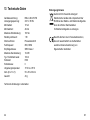
1
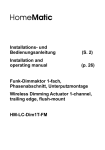
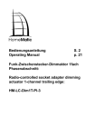
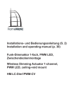
Installations- und
Bedienungsanleitung (S. 2)
Installation and
operating manual (p. 26)
Funk-Dimmaktor 1fach Phasenabschnitt
Unterputzmontage:
Radio-controlled dimming actuator
1-channel trailing edge flush-mount:
HM-LC-Dim1T-FM
Inhaltsverzeichnis
1. Ausgabe Deutsch 02/2012
Dokumentation © 2012 eQ-3 AG, Deutschland
Alle Rechte vorbehalten. Ohne schriftliche
Zustimmung des Herausgebers darf dieses
Handbuch auch nicht auszugsweise in irgendeiner
Form reproduziert werden oder unter Verwendung
elektronischer, mechanischer oder chemischer
Verfahren vervielfältigt oder verarbeitet werden.
Es ist möglich, dass das vorliegende Handbuch noch
drucktechnische Mängel oder Druckfehler aufweist.
Die Angaben in diesem Handbuch werden jedoch
regelmäßig überprüft und Korrekturen in der nächsten
Ausgabe vorgenommen. Für Fehler technischer oder
drucktechnischer Art und ihre Folgen übernehmen wir
keine Haftung.
Alle Warenzeichen und Schutzrechte werden
anerkannt.
Printed in Hong Kong
Änderungen im Sinne des technischen Fortschritts
können ohne Vorankündigung vorgenommen werden.
1
Hinweise zu dieser Anleitung . . . . . . . . . . . . . . 4
2Gefahrenhinweise . . . . . . . . . . . . . . . . . . . . . . . 4
3Funktion . . . . . . . . . . . . . . . . . . . . . . . . . . . . . . 7
4
Allgemeine Systeminformation zu HomeMatic . 9
5
Allgemeine Hinweise zum Funkbetrieb . . . . . . . 9
6Installation . . . . . . . . . . . . . . . . . . . . . . . . . . . . 11
7Inbetriebnahme . . . . . . . . . . . . . . . . . . . . . . . . 15
7.1 Einfache Bedienfunktionen mit
angeschlossenem Taster . . . . . . . . . . . . . . . . . 15
7.2Anlernen . . . . . . . . . . . . . . . . . . . . . . . . . . . . . 16
7.3 Bedienfunktionen nach Anlernen . . . . . . . . . . 18
8
Zurücksetzen in den Auslieferungszustand . . . 19
9
Rückmeldungen der Geräte-LED . . . . . . . . . . 20
9.1Blinkcodes . . . . . . . . . . . . . . . . . . . . . . . . . . . . 20
9.2 Anzeige des Betriebszustandes . . . . . . . . . . . 20
10 Verhalten nach Spannungswiederkehr . . . . . . 21
11
Wartung und Reinigung . . . . . . . . . . . . . . . . . . 22
12 Weitere Betriebshinweise . . . . . . . . . . . . . . . . 22
13 Technische Daten . . . . . . . . . . . . . . . . . . . . . . 24
91900 / V 2.1
2
3
1 Hinweise zu dieser Anleitung
Lesen Sie diese Anleitung sorgfältig, bevor Sie Ihre
HomeMatic Komponenten in Betrieb nehmen.
Bewahren Sie die Anleitung zum späteren
Nachschlagen auf!
Wenn Sie das Gerät anderen Personen zur
Nutzung überlassen, übergeben Sie auch diese
Bedienungsanleitung.
Benutzte Symbole:
Achtung! Hier wird auf eine Gefahr
hingewiesen.
Hinweis. Dieser Abschnitt enthält zusätzliche
wichtige Informationen!
2Gefahrenhinweise
Der beschriebene Aktor ist Teil einer
Gebäudeinstallation. Bei der Planung und
Errichtung von elektrischen Anlagen sind die
einschlägigen Normen und Richtlinien des
Landes zu beachten, in dem die Anlage
installiert wird.
4
Der Betrieb des Gerätes ist ausschließlich am
230V/50Hz-Wechselspannungsnetz zulässig.
Arbeiten am 230V-Netz dürfen nur durch
eine Elektro-Fachkraft (nach VDE 0100)
erfolgen. Dabei sind die geltenden
Unfallverhütungsvorschriften zu beachten.
Bitte öffnen Sie den Aktor nicht. Er enthält keine
durch den Anwender zu wartenden Teile. Im
Fehlerfall nehmen Sie bitte Kontakt mit unserem
Service auf.
Betreiben Sie das Gerät nur in Innenräumen.
Vermeiden Sie den Einfluss von Feuchtigkeit,
Staub sowie Sonnen- oder anderer Wärmebestrahlung.
Beachten Sie beim Anschluss an die
Geräteklemmen die hierfür zulässigen
Leitungen und Leitungsquerschnitte.
Beachten Sie vor Anschluss eines Verbrauchers
die technischen Daten, insbesondere die
maximal zulässige Anschlussleistung des
Dimmers und Art des anzuschließenden
Verbrauchers! Alle Lastangaben beziehen sich
5
auf ohmsche Lasten! Bitte belasten Sie den
Aktor nur bis zur angegebenen Leistungsgrenze.
Der Dimmer ist ausschließlich für Glühlampen
sowie für Hochvolt-Halogenlampen und
Niedervolt-Halogenlampen mit elektronischen
Trafos geeignet! Bitte schließen Sie am
Dimmer nur Lampenlasten und keine
Fernseher, Computer, Motoren etc. an.
Eine Überlastung kann zur Zerstörung des
Gerätes, zu einem Brand oder zu einem
elektrischen Schlag führen.
Vor dem Anschließen des Aktors muss die
Sicherung im Sicherungskasten
herausgenommen werden.
Der Dimmer enthält einen thermischen Schutz.
Bitte beachten Sie, dass bei leichter Erwärmung
die Lampen und Leuchten heruntergedimmt
und bei Überhitzung die Verbraucher ganz
abgeschaltet werden.
Das Gerät ist nicht zum Freischalten geeignet.
Die Last ist nicht galvanisch vom Netz getrennt.
Bei Betrieb mit elektronischen Trafos nur
6
Transformatoren einsetzen, die den
Anforderungen nach DIN EN 61347-1 (VDE
0712-30, Teil 1) sowie DIN EN 61047 (VDE
0712-25, Teil 2) entsprechen.
Schalten Sie zur Vermeidung eines
elektrischen Schlags vor Arbeiten am Gerät die
Netzspannung frei (Sicherungsautomat
abschalten).
Bei Nichtbeachtung der Installationshinweise
können Brand oder andere Gefahren entstehen
(siehe auch Kapitel 6 Installation auf Seite 11).
3Funktion
Das Gerät ist ein Abschnittdimmer für die Montage
in Unterputzdosen. Ein Phasenabschnittdimmer
ermöglicht das Dimmen von normalen Glühlampen,
dimmbaren Energiesparlampen, HochvoltHalogenlampen und Niedervolt-Halogenlampen
mit elektronischem Trafo. Der Aktor steuert
angeschlossene Verbraucher aufgrund von
empfangenen Funkbefehlen. Befehle werden
ausgesandt durch Betätigung von Tastern,
7
Fernbedienungen oder über eine Softwareoberfläche.
Zusätzlich ist es möglich, Aktoren über angelernte
Sensoren anzusteuern. Die Sensoren senden (wie ein
Taster) beim Eintreten eines Ereignisses einen Befehl.
Genaueres dazu ist der Anleitung des entsprechenden
Sensors zu entnehmen.
A
4 Allgemeine Systeminformation
zu HomeMatic
Dieses Gerät ist Teil des HomeMatic-HaussteuerungsSystems und arbeitet mit dem bidirektionalen
BidCoS®-Funkprotokoll.
Alle Geräte werden mit einer Standardkonfiguration
ausgeliefert. Darüber hinaus ist die Funktion
des Gerätes über ein Programmiergerät und
Software konfigurierbar. Welcher weitergehende
Funktionsumfang sich damit ergibt, und welche
Zusatzfunktionen sich im HomeMatic-System
im Zusammenspiel mit weiteren Komponenten
ergeben, entnehmen Sie bitte dem HomeMaticSystemhandbuch.
Alle technischen Dokumente und Updates finden Sie
stets aktuell unter www.HomeMatic.com.
B
AGeräte-LED
BAnschlussklemmen
5 Allgemeine Hinweise zum
Funkbetrieb
Die Funk-Übertragung wird auf einem nicht exklusiven
Übertragungsweg realisiert weshalb Störungen nicht
8
9
ausgeschlossen werden können.
Weitere Störeinflüsse können hervorgerufen werden
durch Schaltvorgänge, Elektromotoren oder defekte
Elektrogeräte.
Die Reichweite in Gebäuden kann
stark von der im Freifeld abweichen.
Außer der Sendeleistung und den
Empfangseigenschaften der Empfänger spielen
Umwelteinflüsse wie Luftfeuchtigkeit neben
baulichen Gegebenheiten vor Ort eine wichtige
Rolle.
Hiermit erklärt die eQ-3 AG, dass sich dieses
Gerät in Übereinstimmung mit den grundlegenden
Anforderungen und den anderen relevanten
Vorschriften der Richtlinie 1999/5/EG befindet.
Die vollständige Konformitätserklärung finden Sie
unter www.HomeMatic.com.
10
6Installation
Hinweis! Installation nur durch Personen
mit einschlägigen elektrotechnischen
Kenntnissen und Erfahrungen!
Durch eine unsachgemäße Installation gefährden Sie
•
Ihr eigenes Leben;
•
das Leben der Nutzer der elektrischen Anlage.
Mit einer unsachgemäßen Installation riskieren Sie
schwere Sachschäden, z.B. durch Brand. Es droht
für Sie die persönliche Haftung bei Personen- und
Sachschäden.
Wenden Sie sich an einen Elektroinstallateur!
Erforderliche Fachkenntnisse für die Installation:
Für die Installation sind insbesondere folgende
Fachkenntnisse erforderlich:
•
Die anzuwendenden ‚5 Sicherheitsregeln‘:
Freischalten; gegen Wiedereinschalten sichern;
Spannungsfreiheit feststellen; Erden und
Kurzschließen; benachbarte, unter Spannung
stehende Teile abdecken oder abschranken;
•
Auswahl des geeigneten Werkzeuges,
der Messgeräte und ggf. der persönlichen
Schutzausrüstung;
11
•
•
•
•
•
Auswertung der Messergebnisse;
Auswahl des Elektro-Installationsmaterials zur
Sicherstellung der Abschaltbedingungen;
IP-Schutzarten;
Einbau des Elektroinstallationsmaterials;
Art des Versorgungsnetzes (TN-System, ITSystem, TT-System) und die daraus folgenden
Anschlussbedingungen (klassische Nullung,
Schutzerdung, erforderliche Zusatzmaßnahmen
etc.).
Die Installation darf nur in handelsüblichen Schalterdosen (Gerätedosen) gemäß DIN 49073-1 erfolgen.
Bei Einbau von mehreren Unterputzaktoren in
nebeneinander oder übereinander liegenden
Installationsdosen (verbunden oder
unverbunden) darf ein Gesamtschaltstrom von
16A nicht überschritten werden!
gegeben. Führen Sie die geschaltete Phase zum
Verbraucher.
Am Gerät selbst sind keine Bedienelemente
vorhanden. Zum direkten Anlernen ohne HomeMatic
Zentrale müssen Sie (wenn auch nur temporär) einen
Taster anschließen!
Der Steuereingang wird mit Netzspannung
beschaltet. Verwenden Sie ausschließlich
netzspannungsfeste Taster und Leitungen!
Schließen Sie an den Eingang nur Taster
und keine Schalter an! Dieses würde zur
Fehlfunktion des Gerätes führen!
Bitte notieren Sie sich vor der Installation die
auf dem Gerät angebrachte Seriennummer
(10-stellig unter dem Barcode) und den
genauen Installationsort, damit Sie das Gerät
später einfacher über die Bedienoberfläche der
HomeMatic-Zentrale einrichten können.
Die Installation des beschriebenen Aktors ist im
nachfolgenden Anschlussbild dargestellt.
Zur Versorgung schließen Sie den Aktor an L und N
an.
Auf den Tastereingang wird zum Tasten Phase
12
13
HM-LC-Dim1T-FM
L
N
PE
1
1
Starre Leitung Flexible
[mm2]
Leitung ohne
Aderendhülse
[mm2]
Flexible
Leitung mit
Aderendhülse
[mm2]
0,75 – 1,50
0,75
0,75 - 1,50
7Inbetriebnahme
7.1 Einfache Bedienfunktionen mit
angeschlossenem Taster
1
Gedimmte Phase
N
Anschluss Neutralleiter (Last)
L
Anschluss Außenleiter
S1
Eingang für Taster (Phase)
Zugelassene Leitungsquerschnitte zum Anschluss an
den Unterputz-Aktor:
14
Über einen externen Taster können Sie den Aktor
sofort bedienen (Anlernen nicht erforderlich) und die
korrekte elektrische Installation überprüfen. Bereits
vorhandene Taster können Sie weiter verwenden.
Der kurze Tastendruck schaltet die Last ein und aus.
Der lange Tastendruck hat zwei Funktionen:
•
Innerhalb der ersten 5 Minuten nach dem
Zuschalten der Netzspannung wird hierüber der
Anlernmodus aktiviert.
•
Nach Ablauf der 5 Minuten erfolgt durch einen
langen Tastendruck das Dimmen. Bei jedem
Tastendruck wechselt die Dimmrichtung.
15
7.2Anlernen
Bitte lesen Sie diesen Abschnitt erst
vollständig, bevor Sie mit dem Anlernen
beginnen!
Damit HomeMatic Komponenten miteinander
kommunizieren können, müssen diese aneinander
angelernt werden.
Zum Anlernen müssen die beiden zu verknüpfenden
Geräte in den Anlernmodus gebracht werden.
Der Aktor besitzt keine spezielle Anlerntaste.
Schließen Sie zum Anlernen einen geeigneten
spannungsfesten Taster an den Tastereingang an
(siehe Abschnitt Installation). Zum Anlernen halten
Sie innerhalb der ersten 5 Minuten nach Zuschalten
der Netzspannung den Taster für etwa 4 Sekunden
gedrückt.
Dauerhaftes Blinken der Geräte-LED signalisiert den
Anlernmodus.
Wenn kein Anlernen erfolgt, wird der Anlernmodus
automatisch nach 20 Sekunden beendet. Befinden
sich andere Geräte im Anlernmodus, werden diese
angelernt.
16
7.2.1 Anlernen an eine Zentrale oder einen
Konfigurations-Adapter
Um den Aktor komfortabel über eine Bedienoberfläche
verknüpfen oder in Zentralenprogrammen nutzen
zu können, muss der Aktor an die entsprechende
Zentrale angelernt werden. Hierzu ist zunächst der
Anlernmodus der Zentrale zu starten. Während der
60-sekündigen Suche ist der Anlernmodus des Aktors
zu starten. Die LED des Aktors blinkt und leuchtet,
bis der Anlernvorgang abgeschlossen ist. Wenn die
Zentrale den Anlernvorgang nicht bestätigt, blinkt die
LED 20 Sekunden, bis sie erlischt.
Alternativ zur Suche kann die Seriennummer
des Aktors auch direkt in das vorgesehene Feld
eingegeben und der Aktor angelernt werden. Sobald
eine Komponente an eine Zentrale angelernt ist, kann
sie nur noch über diese mit anderen Komponenten
verknüpft werden. Jede Komponente kann immer nur
an eine Zentrale angelernt werden.
7.2.2 Direktes Anlernen an Sender
Wenn der Aktor noch an keine Zentrale angelernt ist,
kann er direkt an passende HomeMatic Sender wie
z.B. Fernbedienungen angelernt werden.
17
•
•
•
•
•
Aktivieren Sie den 20-sekündigen Anlernmodus
des Aktors (innerhalb der ersten 5 Minuten nach
Zuschalten der Netzspannung).
Ein Blinken der LED zeigt den aktiven
Anlernvorgang an.
Aktivieren Sie nun den Anlernmodus des
anzulernenden Senders und wählen ggf. die
gewünschte Kanaltaste.
Sobald beide Komponenten den Anlernvorgang
abgeschlossen haben, erlöschen die LEDs
und der Aktor kann über den Sender in einer
Standardkonfiguration bedient werden.
Durch nachträgliches Anlernen der
Komponenten an eine Zentrale oder einen
Konfigurationsadapter stehen erweiterte
Konfigurationsmöglichkeiten für diese direkte
Verknüpfung zwischen Sender und Aktor zur
Verfügung.
7.3 Bedienfunktionen nach Anlernen
Nach dem Anlernen stehen einfache Bedienfunktionen
über die angelernten Sender zur Verfügung. Kurzer
Tastendruck: AN/AUS, langer Tastendruck: Dimmen.
Dabei ergibt sich folgendes Verhalten:
18
Taste
Verhalten
Kurzer Tastendruck
„EIN“-Taste
AN
Kurzer Tastendruck
„AUS“-Taste
AUS
Langer Tastendruck
„EIN“-Taste
Hoch dimmen
Langer Tastendruck
„AUS“-Taste
Runter dimmen
Je nach angelerntem Bedienelement lässt sich das
Schalten im Toggle-Betrieb und das Dimmen über den
Eintasten-Betrieb realisieren.
Über den externen Taster ist das Gerät auch direkt
bedienbar.
8 Zurücksetzen in den
Auslieferungszustand
Um den Aktor in den Auslieferungszustand
zurückzusetzen, versetzen Sie das Gerät nach Abund Wiederzuschalten der Netzspannung über den
externen Taster in den Anlernmodus (mindestens
19
4 Sekunden Taste gedrückt halten). Befindet sich
das Gerät im Anlernmodus, halten Sie erneut die
Kanaltaste für mindestens 4 Sekunden gedrückt.
Schnelles Blinken der Geräte-LED zeigt das
Rücksetzen des Aktors an.
9 Rückmeldungen der Geräte-LED
9.1Blinkcodes
Verschiedene Zustände des Aktors werden durch
Blinken der Kanal-LED angezeigt:
Langsames Blinken
Anlernmodus
Schnelles Blinken
Reset
Einmal lang, n-mal kurz
(je nach Fehlerart)
Fehler
9.2 Anzeige des Betriebszustandes
Sobald der Dimmer eingeschaltet ist, leuchtet die
Geräte-LED dauerhaft.
Nach Konfiguration des Aktors über die Zentrale oder
über ein Programmiertool zeigt die Geräte-LED neben
20
den beschriebenen noch zusätzliche Zustände des
Geräts an.
10 Verhalten nach
Spannungswiederkehr
Nach dem Einschalten der Betriebsspannung
(Wiederkehr der Netzspannung) überprüft der
Aktor seine Komponenten. Sollte dabei ein Fehler
festgestellt werden, so wird dieses durch Blinken der
LED dargestellt. Dieses wiederholt sich kontinuierlich
und das Gerät nimmt seine eigentliche Funktion nicht
auf.
Sollte der Test ohne Fehler durchlaufen, sendet
der Aktor ein Funktelegramm mit seiner
Statusinformation aus.
Damit bei Spannungswiederkehr (etwa nach
Netzspannungsausfall oder Abschaltung) nicht alle
Aktoren gleichzeitig senden, wartet der Aktor eine
zufällige Verzögerungszeit vor dem Senden. In dieser
Zeit blinkt die Geräte-LED (wie im Anlernmodus). Ist
die Verzögerungszeit sehr kurz, kann es sein, dass
das Blinken kaum wahrnehmbar ist.
21
11 Wartung und Reinigung
Das Produkt ist wartungsfrei. Überlassen Sie
eine Reparatur einer Fachkraft.
Bei Betrieb des Aktors über die Zentrale des
HomeMatic-Systems (CCU) ist zu beachten,
dass die Zentrale keine Information bei einem
Lastausfall erhält.
Das Gerät enthält eine interne Gerätesicherung zum Schutz der Elektronik vor zu
großer Strombelastung. Sollte das Gerät
überlastet werden und die Sicherung auslösen,
darf sie nur von unserem Service ersetzt
werden!
Vor Ausbau des Gerätes unbedingt
Netzspannung freischalten (Sicherungsautomat
abschalten)! Arbeiten am 230V-Netz dürfen nur
von einer Elektro-Fachkraft (nach VDE 0100)
erfolgen.
12 Weitere Betriebshinweise
Erwärmt sich das Gerät im Betrieb zu stark, z. B. durch
ungenügende Luftzirkulation, erfolgt zunächst eine
Lastreduzierung in Form einer Helligkeitsabsenkung,
bei anhaltender Übertemperatur erfolgt ein Abschalten
der Last.
22
23
13 Technische Daten
Gerätebezeichnung:HM-LC-Dim1T-FM
Versorgungsspannung:
230 V / 50 Hz
Minimallast:
10 VA
Minimalstrom:
40 mA
Maximale Schaltleistung:
180 VA
Standby-Verbrauch:
1W
Dimmverfahren:Phasenabschnitt
Funkfrequenz: 868,3 MHz
Empfängerklasse:
SRD Class 2
Maximale Sendeleistung:
10 mW
Typ. Freifeldreichweite:
100 m
Schutzart:IP20
Schutzklasse:II
Umgebungstemperatur:
+5°C bis +35°C
Abm. (B x H x T):
53 x 53 x 30 mm
Gewicht:
43 g
Entsorgungshinweis
Gerät nicht im Hausmüll entsorgen!
Elektronische Geräte sind entsprechend der
Richtlinie über Elektro- und Elektronik-Altgeräte
über die örtlichen Sammelstellen
für Elektronik-Altgeräte zu entsorgen.
Das CE-Zeichen ist ein Freiverkehrszeichen,
das sich ausschließlich an die Behörden
wendet und keine Zusicherung von
Eigenschaften beinhaltet.
Technische Änderungen vorbehalten.
24
25
Table of contents
1st English edition 02/2012
Documentation © 2012 eQ-3 AG, Germany
All rights reserved. This manual may not be
reproduced in any format, either in whole or in part,
nor may it be duplicated or edited by electronic,
mechanical or chemical means, without the written
consent of the publisher.
Typographical and printing errors cannot be excluded.
However, the information contained in this manual
is reviewed on a regular basis and any necessary
corrections will be implemented in the next edition. We
accept no liability for technical or typographical errors
or the consequences thereof.
All trademarks and industrial property rights are
acknowledged.
Printed in Hong Kong
Changes may be made without prior notice as a result
of technical advances.
1
Information about this manual . . . . . . . . . . . . . 28
2
Hazard information . . . . . . . . . . . . . . . . . . . . . 28
3Function . . . . . . . . . . . . . . . . . . . . . . . . . . . . . 31
4
General system information
about HomeMatic . . . . . . . . . . . . . . . . . . . . . . . 33
5
General information
about radio operation . . . . . . . . . . . . . . . . . . . 33
6Installation . . . . . . . . . . . . . . . . . . . . . . . . . . . . 34
7Start-up . . . . . . . . . . . . . . . . . . . . . . . . . . . . . . 38
7.1 Simple operator functions using
connected buttons . . . . . . . . . . . . . . . . . . . . . . 38
7.2Teaching-in . . . . . . . . . . . . . . . . . . . . . . . . . . . 39
7.3 Operating functions after teach-in . . . . . . . . . . 42
8
Resetting to the initial state . . . . . . . . . . . . . . . 43
9
Device LED feedback . . . . . . . . . . . . . . . . . . . 43
9.1 Flashing codes . . . . . . . . . . . . . . . . . . . . . . . . 43
9.2 Operating status display . . . . . . . . . . . . . . . . . 44
10 Response to power recovery . . . . . . . . . . . . . 44
11
Maintenance and cleaning . . . . . . . . . . . . . . . 45
12 Other notes on operation . . . . . . . . . . . . . . . . 46
13 Technical data . . . . . . . . . . . . . . . . . . . . . . . . . 47
91900 / V 2.1
26
27
1 Information about this manual
Read this manual carefully before starting to use your
HomeMatic components.
Keep the manual so you can refer to it at a later date
if you need to!
If you hand over the device to other persons for use,
please hand over the operating manual as well.
Symbols used:
Attention!
This indicates a hazard.
Note. This section contains additional important
information.
2 Hazard information
The actuator that is described is part of a
building installation. When planning and setting
up electrical installations, the standards and
guidelines that are applicable in the country in
which the equipment is installed must be
complied with.
28
The device has been designed solely for
operation on a 230 V/50 Hz AC supply. Only
qualified electricians (to VDE 0100) are
permitted to carry out work on the 230 V mains.
Applicable accident prevention regulations
must be complied with whilst such work is
being carried out.
Please do not open the actuator. It does not
contain any parts that can be maintained by the
user. In the event of a fault, please call our
service department.
The device must only be operated indoors.
Protect the device from the effects of damp and
dust, as well as solar or other methods of heat
radiation.
When connecting to the device terminals, take
the permissible cables and cable cross
sections into account.
Please take the technical data (in particular the
maximum permissible switching capacity of the
relay and the type of load to be connected) into
account before connecting a load! All load data
29
relates to resistive loads! Please do not exceed
the capacity specified for the actuator.
The dimmer is only suitable for light bulbs and
high-voltage and low-voltage halogen lamps
with electronic transformers! Please only
connect lamp loads to the dimmer, and not
televisions, computers, motors etc.
To avoid electric shock, disconnect the mains
voltage prior to starting work on the device (trip
the miniature circuit-breaker).
Exceeding this capacity could lead to the
destruction of the device, fires or electric
shocks.
Noncompliance with the installation instructions
can cause fire or introduce other hazards (see
also chapter 6 Installation on page 34).
Before connecting the actuator is connected,
remove the fuse from the fuse box.
The dimmer contains a thermal cut-off. Please
note that if a small amount of heating occurs
the lamps and luminaires will be dimmed, and
in the event of overheating the loads will be
switched off altogether.
The device has not been designed to support
safety disconnection. The load is not isolated
from the mains.
If the dimmer is being operated with electronic
30
transformers, only those which meet the
requirements of DIN EN 61347-1 (VDE 071230, Part 1) along with DIN EN 61047 (VDE
0712-25, Part 2) may be used.
3Function
The device is a reverse phase control dimmer for
installing in flush-mounted boxes. A reverse phase
control dimmer makes it possible to dim normal
incandescent lamps, dimmable energy-saving lamps,
high-voltage halogen lamps and low-voltage halogen
lamps with an electronic transformer. The actuator
controls connected loads in accordance with the
wireless commands it receives. Commands are
transmitted by actuating buttons or remote controls,
31
or via a software interface. It is also possible to
control actuators via taught-in sensors. When an
event occurs, the sensors transmit a command (in the
same way as a button). Refer to the manual for the
corresponding sensor for more detailed information.
A
4 General system information
about HomeMatic
This device is a constituent of the HomeMatic home
control system, and operates using the bi‑directional
BidCoS® wireless protocol.
All devices are delivered in a standard configuration.
The functionality of the device can also be configured
with a programming device and software. The
additional functions that can be made available in this
way and the supplementary functions provided by the
HomeMatic system when it is combined with other
components are described in the HomeMatic System
Manual.
All current technical documents and updates are
provided at www.HomeMatic.com.
B
A
B
Device LED
Connecting terminals
5 General information about radio
operation
Radio transmission is performed on a non-exclusive
transmission path, which means that there is a
possibility of interference occurring.
32
33
Interference can also be caused by switching
operations, electrical motors or defective electrical
devices.
The range of transmission within buildings can
deviate greatly from open air distances.
Besides the transmitting power and the
reception characteristics of the receiver,
environmental factors such as humidity in the
vicinity have an important role to play, as do
on-site structural/screening conditions.
eQ-3 AG hereby declares that this device conforms
with the essential requirements and other relevant
regulations of Directive 1999/5/EC.
The full declaration of conformity is provided at www.
HomeMatic.com.
6Installation
Note. Only to be installed by persons with
the relevant electro-technical knowledge
and experience!
34
Incorrect installation can put
•
your own life at risk;
•
and the lives of other users of the electrical
system.
Incorrect installation also means that you are running
the risk of serious damage to property, e.g. because
of a fire. You may be personally liable in the event of
injuries or damage to property.
Contact an electrical installer!
Specialist knowledge required for installation:
The following specialist knowledge is particularly
important during installation:
•
The ‚5 safety rules‘ to be used:
Disconnect from mains; Safeguard from
switching on again; Check that system is
deenergised; Earth and short circuit; Cover or
cordon off neighbouring live parts;
•
Select suitable tool, measuring equipment and, if
necessary, personal safety equipment;
•
Evaluation of measuring results;
•
Selection of electrical installation material for
safeguarding shut-off conditions;
•
IP protection types;
35
•
•
Installation of electrical installation material;
Type of supply network (TN system, IT system,
TT system) and the resulting connecting
conditions (classical zero balancing, protective
earthing, required additional measures etc.).
The control input is switched with mains
voltage. Only pushbuttons and cables that are
rated for mains voltage may be used! Only
connect pushbuttons at the input, not switches!
This would make the device malfunction!
Installation may only take place in normal commercial
switch boxes (device boxes) in accordance with DIN
49073-1.
When installing many flush-mount actuators in
installation boxes that are one above the other
or adjacent to one another (connected or not),
the total switching current of 16 A is not to be
exceeded!
The installation of the actuator that is described is
shown in the following connection diagram.
Connect the actuator to L and N to obtain a power
supply.
Phase for pushbuttons is provided at the pushbutton
input. Route the switched phase to the consumer.
There are no controls on the device itself. A
pushbutton must be connected (even if it is only
temporary) for direct teach-ins without the HomeMatic
central control unit.
36
Before installation, please note the serial
number on the device (10 digits, beneath
barcode) and the exact installation location so
that you can set up the device later via the user
interface of the HomeMatic central control unit.
HM-LC-Dim1T-FM
L
N
PE
1
1
37
1
Dimmed phase
N
Neutral conductor connection (load)
L
Phase conductor connection
S1
Input for pushbutton (phase)
Permitted cable cross sections for connecting to the
flush-mounted actuator:
Rigid cable
[mm2]
0.75 – 1.50
Flexible cable
without
ferrule
[mm2]
Flexible cable
with
ferrule
[mm2]
0.75 - 1.50
0.75
7Start-up
7.1 Simple operator functions using
connected pushbutton
The actuator can be operated immediately using an
external pushbutton (no teach-in required) for checking
that the electrical installation is correct. Existing
pushbuttons can continue to be used.
38
A short press of the pushbutton switches the load
on and off. A long press of the pushbutton has two
functions:
•
If this occurs within the first 5 minutes of
switching on the mains voltage, teach-in mode
is activated.
•
If a long pushbutton press occurs after these
5 minutes, dimming takes place. The dimming
direction changes with each pushbutton press.
7.2Teaching-in
Please read this entire section before starting
the teach-in procedure.
HomeMatic components have to be taught in to each
other in order to communicate.
To execute the teach-in procedure, both of the devices
to be linked must be in teach‑in mode.
The actuator does not have a special teach-in button.
To teach in the actuator, connect a suitable voltagestable pushbutton to the pushbutton input (see
Installation section). To teach in the actuator, press
and hold down the pushbutton for about 4 seconds
within the first 5 minutes of switching on the mains
voltage.
39
The device LED will flash continuously to indicate that
teach-in mode is active.
If no teach-in operations are carried out, teach-in
mode will be exited automatically after 20 seconds. If
other devices are also in teach-in mode, they will be
taught-in.
7.2.1 Teaching in at a central control unit or
configuration adapter
In order to connect the actuator conveniently via a
user interface or use it in central control unit programs,
the actuator must be taught in at the relevant central
control unit. In order to do this, teach-in mode must
first be started. During the 60-second search, the
Config button (B) of the actuator must be briefly
pressed with a pointed object (e.g. ballpoint pen).
The LED of the Config button flashes and illuminates
until the teach-in procedure is complete. If the central
control unit does not confirm the teach-in procedure,
the LED flashes for 20 seconds and goes off.
As well as searching, the serial number of the actuator
can also be entered directly into the field provided
and the actuator taught in. As soon as a component
has been taught in at a central control unit, it can only
be connected to other components via this unit. Each
40
component can only be taught in at one central control
unit.
7.2.2 Teaching in directly at transmitter
If the actuator has not yet been taught in at a central
control unit, it can be taught in directly at suitable
HomeMatic transmitters such as remote controls.
•
Briefly press the Config button of the actuator
with a pointed object (e.g. ballpoint pen) to start
the 20-second teach-in mode again.
•
Flashing of the LED in the Config button
indicates that teach-in mode is active.
•
Now activate teach-in mode of the transmitter
to be taught in and select the required channel
button if necessary.
•
A soon as both components have completed
the teach-in procedure, the LED’s go off and the
actuator can be operated via the transmitter in a
standard configuration.
•
Subsequent teaching in of the components at
a central control unit or a configuration adapter
provides additional configuration options for this
direct connection between the transmitter and
the actuator.
41
7.3 Operating functions after teach-in
8 Resetting to the as-delivered state
After the teach-in has been performed, simple operator
functions are available via the taught-in transmitter.
Press and release the button: ON/OFF, press and hold
down the button: Dim. Press the button as follows to
trigger the corresponding response:
To reset the actuator to the as-delivered state, put the
device into teach-in mode using the external button
(hold down for at least 4 seconds) after switching the
mains voltage off and back on again. When the device
is in teach-in mode, hold the channel button down for
at least 4 seconds again. If the device LED flashes
quickly, this indicates that the actuator is being reset.
Button
Response
Press and release "ON"
button
ON
Press and release
"OFF" button
OFF
Press and hold down
"ON" button
Dim up
Press and hold down
"OFF" button
Dim down
Depending on the taught-in control element, switching
can be carried out in toggle mode and dimming carried
out using single button mode.
The device can also be operated directly using the
external pushbutton.
42
9 Device LED feedback
9.1 Flashing codes
Various actuator states are indicated by the channel
LED flashing:
Slow flashing
Teach-in mode
Fast flashing
Reset
One long flash, n brief
flashes (depending on
the type of error)
Error
43
9.2 Operating status display
The device LED lights up permanently as soon as the
dimmer is switched on.
Once the actuator has been configured via the central
control unit or a programming tool, the device LED
will indicate other device states in addition to those
already described.
10 Response to power recovery
When the operating voltage is switched on (recovery
of mains voltage), the actuator checks its components.
The LED will flash if an error is detected during this
check. This is repeated continuously and the device
does not perform its function.
If the test is completed without errors, the actuator
transmits a wireless telegram containing its status
information.
To prevent all actuators from transmitting at the same
time when power is recovered (after a mains power
failure or a disconnection, for example), there is a
random delay before the actuator transmits.
During this time, the device LED flashes (as in teach-in
44
mode). If the delay is very short, this flashing may be
almost imperceptible.
11 Maintenance and cleaning
The product does not require any maintenance.
Enlist the help of an expert to carry out any
repairs.
The device features an internal miniature fuse
to protect the electronics against current
overload. If the device is overloaded and the
fuse blows, it can only be replaced by our
service department!
The mains voltage must be disconnected
before the device is removed (trip the miniature
circuit-breaker)! Only qualified electricians (to
VDE 0100) are permitted to carry out work on
the 230 V mains.
45
12 Other notes on operation
13 Technical data
If the device reaches too high a temperature during
operation (due to insufficient air circulation, for
example), the load will first of all be reduced by
lowering the brightness. If the overtemperature
persists, the load will be disconnected.
Device designation:
HM-LC-Dim1T-FM
Power supply:
230 V / 50 Hz
Minimum load:
10 VA
Maximum current:
40 mA
Effective installed load:
180 VA
Standby consumption:
1W
Dimming procedure:
Reverse phase control
Radio frequency: 868,3 MHz
Receiver class:
SRD Class 2
Maximum transmit power:
10 mW
Typ. open air range: 100 m
Degree of protection:
IP20
Protection class: II
Ambient temperature:
+5°C to +35°C
Dimensions (W x H x D): 53 x 53 x 30 mm
Weight:43 g
If the actuator is operating via the HomeMatic
central control unit (CCU), please note that the
central control unit will not be informed in the
event of a load failure.
46
47
Instructions for disposal
Do not dispose of the device with regular domestic
waste! Electronic equipment must be disposed of at
local collection points for waste electronic equipment in compliance with the Waste Electrical and
Electronic Equipment Directive.
The CE sign is a free trade sign addressed
exclusively to the authorities and does not
warrant any properties.
48
49
50
51
Bevollmächtigter des Herstellers:
Manufacturer’s authorised representative:
eQ-3 AG
Maiburger Straße 29
26789 Leer / GERMANY
www.eQ-3.de
52