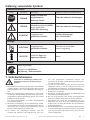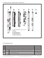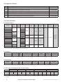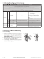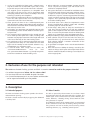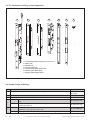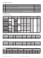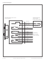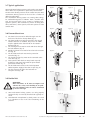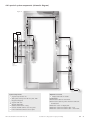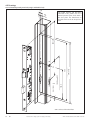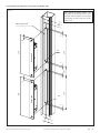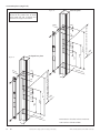
1
Steuerung Netzteil Mechatronisches Schließsystem zum Öffnen von Türen in Paniksituationen, mit elektromotorischer Öffnungsfunktion für Einfachverriegelung Montageanleitung Mechatronic Locking System for door opening in emergency situations, with electro-motorised opener function for single-point locking Assembly Instruction Original Montageanleitung..........................Seite 3 Original Assembly Instruction .....................Page23 Inhalt Seite Erklärung verwendeter Symbole....................................3 1.Sicherheitshinweise.................................................3 2.Ausschluss nicht bestimmungsgemäßer Verwendung..............................................4 3.Beschreibung...........................................................4 3.1Zweckbestimmung............................................4 3.2Arbeitsweise.....................................................4 3.3 Komponenten des mech. Schließsystems...........5 3.4Standardlieferumfang.......................................5 3.5 Optionales Zubehör..........................................6 3.6 Technische Daten 3.6.1 Motorschlösser........................................6 3.6.2 Netzteil...................................................6 3.6.3 Steuerung...............................................6 3.6.4Belegung der WAGO© Klemme der Steuerleitung.....................................7 3.6.5 Anschlussplan.........................................7 3.7 Typische Anwendungen....................................8 3.8 Vorhersehbarer Fehlgebrauch...........................8 3.9Restrisiken........................................................8 4. Bearbeitung der Profile 4.1 Allgemeines......................................................9 4.2 Hinweise zur Bearbeitung der Profile................9 Seite 4.3 Hinweise zu den Zeichnungen...........................9 4.3.1Allgemeine Hinweise zu den Zeichnungen................................9 4.2.2 Hinweise zu Abbildung 3........................9 4.3.3 Hinweise zu Abbildung 4........................9 4.3.4 Hinweise zu Abbildung 5 & 6..................9 4.3.5 Hinweise zu Abbildung 7........................9 4.4 Anordnung der Systemkomponenten..............10 4.5Zeichnungen 4.5.1 Sv-Panik-Motorschloss..........................11 4.5.2 Steuerung und Netzteil.........................12 4.5.3 Schließbleche........................................13 4.5.4Standflügel mit Sv-Panik-Gegenkasten.................... 14-15 4.5.5 Berechnung der Stangenlänge für Sv-Panik-Gegenkasten.....................16 4.5.6 Kabelübergang lang..............................17 4.5.7 Kabelübergang kurz..............................18 5. Montage .............................................................19 5.1Allgemeines....................................................19 5.2 Benötigte Ausrüstung.....................................19 5.3 Montage der Komponenten............................19 5.4 Entsorgung / Recycling...................................19 6.Inbetriebnahme 6.1 Einstellen der Steuerfalle..................................20 6.2 mechanische Funktionskontrolle......................20 6.3 elektronische Funktionskontrolle.....................20 7. Störungsbeseitigung......................................... 21-22 8. Wartung und Instandhaltung..................................22. Diese Montageanleitung muss dem Monteur / Bediener jederzeit zugänglich sein. Sie ist nach der Montage dem Betreiber zu übergeben. Weitere Exemplare können angefordert werden. 2 DE Die Zertifikate DIN EN 1125 und DIN EN 179 können unter www.wss.de angefordert werden. Mechatronisches Schließsystem für Einfachverriegelung Wilh. Schlechtendahl & Söhne GmbH & Co. KG Erklärung verwendeter Symbole Sicherheitshinweise Symbol STOP Signalwort Bedeutung Mögliche Schäden bei Nichtbeachtung GEFAHR UNMITTELBAR oder möglicherweise drohende Gefahr Tod oder schwerste Verletzungen GEFAHR UNMITTELBAR oder möglicherweise drohende Gefahr durch gefährliche elektrische Spannung Tod oder schwerste Verletzungen VORSICHT möglicherweise gefährliche Situation Leichte Verletzungen oder Sachschäden ACHTUNG möglicherweise gefährliche Situation Schäden am Gerät oder seiner Umgebung WICHTIG nützliche Tipps zum optimalen Arbeiten Keine Sonstige Gebote (ohne Signalwort) Hinweis zur schriftlichen Ausführung / Dokumentation 1. Sicherheitshinweise Vermeiden Sie Verletzungen, Schäden und Fehlfunktion indem Sie alle Anweisungen befolgen. a)Mechatronische Schließsysteme der Wilh. Schlechtendahl & Söhne GmbH & Co.KG (im folgenden WSS genannt) sind zum Einbau in ein- und zweiflügelige Türen vorgesehen. b)Bevor das mechatronische Schließsystem in einer Feuerschutz- bzw. Rauchschutztür installiert wird, sind die Länderspezifischen Zulassungsbedingungen für das einzelne Profilsystem zu überprüfen. Die „Dauer-AUF-Funktion“ ist im FH- und RD-Bereich generell nicht zulässig! c)Mit Einbau und Wartung des mechatronischen Schließsystems dürfen nur Personen beauftragt werden, die hiermit vertraut sind. Sie müssen vom Unternehmer mit dem Einbau und der Wartung beauftragt sein. d) Sie müssen die einschlägigen Normen und Vorschriften (z.B. DIN EN 1125, DIN EN 179, etc..) kenWilh. Schlechtendahl & Söhne GmbH & Co. KG nen und entsprechend unterwiesen worden sein. Sie müssen die von WSS erstellte Montageanleitung gelesen und verstanden haben. e)Ist mehr als eine Person mit einer der oben genannten Tätigkeiten betraut, so hat der Unternehmer einen Aufsichtführenden zu bestimmen, der weisungsbefugt ist. f)Nur einwandfreie Komponenten, Schlösser, Beschlagteile, Netzteile etc. verwenden. g)Vor Beginn der Montage alle Teile auf Vollzähligkeit und fehlerfreie Beschaffenheit prüfen. h)Die Tür ist auf korrekte, bzw. leichte und ungehinderte Öffnung zu prüfen und darf keinen Verzug aufweisen. i) Beim Einsatz von Profil und Türdichtungen muss gewährleistet sein, dass diese den bestimmungsgemäßen Gebrauch der Tür bzw. die Funktion des Türverschlusses nicht beeinträchtigen. j)Bei zweiflügeligen Türen mit überfälztem Mittelanschlag, an denen beide Flügel mit Panikverschlüssen ausgerüstet sind, muss sich jeder Flügel öffnen lassen, wenn sein Verschluss betätigt wird. Mechatronisches Schließsystem für Einfachverriegelung DE 3 k) Alle Systemkomponenten wurden aufeinander abgestimmt und dürfen nicht mit Fremdprodukten kombiniert werden. Im Falle von Schäden bei Zuwiderhandlung übernimmt WSS keinerlei Haftung. m)Das Entfernen oder Verlängern der vorkonfektionierten Steckverbindungen des Kabelsystems oder die Verwendung eines fremden Kabelsystems führen zum Verlust der Garantieansprüche. n)Die Steuerung sowie das Sv-Panik-Motorschloss dürfen niemals direkt mit einer 230 V Versorgungsspannung betrieben werden! Zuwiderhandlung führt zur Zerstörung des Sv-Panik-Motorschlosses und kann zum Brand führen. o)Verwenden Sie ausschließlich das mitgelieferte 12V DC Netzteil von WSS, um Schäden an Steuerung und SvPanik-Motorschloss zu vermeiden. p) Die maximale Leitungslänge zwischen Steuerung und Sv-Panik-Motorschloss beträgt 20m, inklusive des Kabelübergangs. Wird diese unsachgemäß verlängert, erlischt die Garantie auf das gesamte Schließsystem. q) Die Steuerung des Sv-Panik-Motorschlosses ist vor Feuchtigkeit zu schützen. Sie ist nicht geeignet für Bereiche mit hoher Luftfeuchtigkeit und chemischen Substanzen (z.B. Galvanik, Schwimmbäder, etc.). r) Beim Einsatz in stark frequentierten Türen ist es erforderlich die DAUER-AUF-Funktion zu nutzen. Die „Dauer-AUF-Funktion“ ist im FH- und RD-Bereich generell nicht zulässig! s)Beim Beenden der „DAUER-AUF“-Funktion muss das Schloss bei geschlossenen Flügeln einen Öffnungszyklus ausführen um vollständig verriegelt zu sein. t)Falls die zu befestigenden Paniktürverschlüsse an zweiflügeliegen Türen mit überfälzten Mittelanschlag und Türschließern vorgesehen sind, muss ein Schließfolgeregler nach DIN 1158 mit Mitnehmerklappe installiert werden, oder eine in die Schließanlage integrierte Schließfolgeregelung, um die richtige Schließfolge der Tür zu gewährleisten. Dies ist für Feuerschutz- und Rauchschutztüren besonders wichtig. u)Falls ein Türschließer installiert wird, muss darauf geachtet werden, dass hierdurch die Betätigung der Tür durch Kinder, Behinderte und ältere Personen nicht erschwert wird. v) Vorgesehene Bodenschließmulden, Schließbleche bzw. Schließmulden müssen gemäß der Anleitung installiert werden, sodass die Übereinstimmung mit dem geprüften Normelement sichergestellt ist. Abweichungen aufgrund unterschiedlicher Türprofile sind nur in Absprache mit WSS zulässig. w)Die Funktion ist nur bei abgezogenem Schlüssel gewährleistet. x)Der Einsatz von Knaufzylindern ist möglich, wenn die Schlösser hierfür vorbereitet sind (z.B. Sonderausführung 124). Es dürfen nur elektronische Knaufzylinder ohne Rückstellmechanismus für die Mitnehmernase zum Einsatz kommen. y)Auf dem Gehflügel muss ein Schild mit der Aufschrift „Drücken“ angebracht werden. z)Für Schäden aufgrund von nicht durch WSS autorisierte Umbauten und Änderungen an den von WSS gelieferten Bauteilen und Komponenten, sowie aufgrund der Verwendung von Nicht-Originalteilen, übernimmt WSS keinerlei Haftung. 2. Ausschluss nicht bestimmungsgemäßer Verwendungen Der Einsatz von serienmäßigen mechatronischen Schließsystemen und deren Zubehör ist nicht bestimmungsgemäß • bei Umgebungstemperaturen unter -10 °C bzw. über +50 °C • bei Konstruktionen, die nicht für eine Panikfunktion geeignet sind. • für den Einsatz in feuchter Umgebung bzw. dort, wo mit Kondenswasser in den Profilen zu rechnen ist. 3. Beschreibung 3.1 Zweckbestimmung 3.2 Arbeitsweise Das mechatronische Schließsystem von WSS dient dazu, Türen elektromotorisch öffnen zu können. Das Schließen der Tür erfolgt mechanisch durch Auslösen der Zusatzfalle / Steuerfalle. Über einen im Schloss eingebauten Elektromotor, der an ein Getriebe gekoppelt ist, wird das Schloss elektromotorisch geöffnet. Der Schaltimpuls zum Öffnen kann dabei von beliebigen Schaltelementen aus abgegeben werden. Vorraussetzung ist ein potentialfreier Schließkontakt seitens der Schaltelemente. Die einzelnen Zustände des Motorschlosses werden an der Steuerleitung in Form von potentialfreien Schließ- und Wechselschaltkontakten ausgegeben und können mit verschiedenen Schaltelementen wie z.B. einer Gebäudeleittechnik weiterverarbeitet werden. 4 DE Mechatronisches Schließsystem für Einfachverriegelung Wilh. Schlechtendahl & Söhne GmbH & Co. KG 3.3. Komponenten des mechatronischen Schließsystems 2 3 Netzteil Steuerung Abb. 1 1 4 5 6 7 1 Sv-Panik-Motorschloss (Ausführung ab 2011) 2Netzteil 3Steuerung 4 Sv-Panik Gegenkasten 5U-Stulp-Schließblech 6Flachstulp-Schließblech 7 Magnet mit Magnethalter 3.4 Standardlieferumfang Stück Bezeichnung Art.-Nr. 1 Sv-Panik-Motorschloss mit Trafo-Wechsel-Funktion „E“ je nach Ausführung 1 Steuerung mit Edelstahlstulp 01.195.0000.000 1 Netzteil mit Edelstahlstulp 01.198.0100.000 entweder Flachstulp Schließblech mit Magnet zum Reedkontakt des Motorschlosses 01.730.2413.426 1 1 oder U-Stulp Schließblech mit Magnet zum Reedkontakt des Motorschlosses 01.730.2416.426 entweder Kabelübergang lang, trennbar, Kabellänge im Flügel 5m, Blendrahmen 750mm 05.803.0000.026 für max. Öffnungswinkel >90° oder Kabelübergang kurz, Kabellänge 5m, für max. Öffnungswinkel 90° Wilh. Schlechtendahl & Söhne GmbH & Co. KG Mechatronisches Schließsystem für Einfachverriegelung 05.800.1000.026 DE 5 3.5 Optionales Zubehör Stück Bezeichnung Art.-Nr. 1 Anzeigeeinheit (Zustandsanzeige) innen oder außen 01.196.0100.000 1 Kabel-Verlängerung für Anzeigeeinheit 1,5m lang 01.193.0200.000 1 Kabel-Verlängerung für Anzeigeeinheit 3m lang 01.193.0300.000 1 Anschlussleitung für Steuerung, 12-polig, 10m lang 01.192.0200.000 1 Verlängerung vom Kabelübergang zum Schloss 5m lang 01.192.0100.000 1 Verlängerung vom Kabelübergang zur Steuerung10m lang 01.193.0100.000 3.6 technische Daten 3.6.1 Motorschlösser: DIN Richtung Art.-Nr. 01.154.35--.426 01.154.40--.426 01.154.45--.426 01.155.35--.426 01.155.40--.426 01.155.45--.426 01.154.34--.426 01.155.34--.426 01.156.35--.426 01.156.40--.426 01.156.45--.426 01.157.35--.426 01.157.40--.426 01.157.45--.426 01.156.34--.426 01.157.34--.426 rechts links rechts links rechts links rechts links für Dornmaß Anzahl mm Flügel 35 40 45 1 35 oder 40 2 45 34 34 35 40 45 35 2 40 45 34 34 Stulp Vorstand Vorstand Vorstand Falle Riegel Steuerfalle mm mm mm Flachstulp 2 bündig 4,5+2 U-Stulp 3 1 5,5+2 Entfernung mm 92 Flachstulp 2 bündig 4,5+2 U-Stulp 3 1 5,5+2 Material/ BetriebsOberfläche spannung Stulp 12 V DC* Edelstahl V2A, matt gebürstet *) Spannungsversorgung erfolgt direkt über die Steuerung von WSS 3.6.2 Netzteil: Abmessungen Schutz- UmgebungstemperaEingangs(B x H x T) mm art IP tur °C bei Dauerlast spannung V 20 -10 bis +50 230 AC 01.198.0100.000 20 x 198 x 34 Hinweis: Außenleiter und Neutralleiter des Netzteils immer richtig anschließen! Art.-Nr. Leistungsaufnahme ca. 30 W Ausgangsspannung V 12 DC Ausgangsstrom A b. Dauerlast max 2,5 3.6.3 Steuerung: Abmessungen Schutz- Umgebungstempera(B x H x T) mm art IP tur °C bei Dauerlast 20 -10 bis +50 01.195.0000.000 20 x 198 x 34 Hinweis: Einschaltstrom beachten! Art.-Nr. Eingangsspannung V 12 - 36 DC Stromaufnah- Einschaltme mA strom A ca. 850 2,5 / 30 ms Kontaktbelastbarkeit max. 30V / 1A 3.6.4 Belegung der WAGO© Klemme der Steuerleitung: Funktion Klemme Nr. Farbe Ansteuerung motorisch öffnen 1 2 weiß / weiß / schwarz braun (NO) Abfrage entriegelt** 3 4 schwarz weiß (NO) -> (NC) Abfrage verriegelt 5 braun 6 grün (NC) -> (NO) Abfrage Nussbetätigung*** 7 8 9 orange rot gelb (NO) (C) (NC) Abfrage Magnetkontakt 10 11 12 violett blau grau (NO) (C) (NC) **) für die Ansteuerung von Drehtürantrieben zeitlich auf 3 Sek. begrenzt. ***) optional 6 DE Mechatronisches Schließsystem für Einfachverriegelung Wilh. Schlechtendahl & Söhne GmbH & Co. KG 3.6.5 Anschlussplan Kontaktzustände des Schlosses in Stellung "verriegelt" an der 12-poligen Steuerleitung. motorisch öffnen GND bauseitiges Steuerelement z.B. Relais, Biometrie, Schalter, Taster etc. Klemme Farbcode 1 weiß / braun 2 weiß / schwarz potentialfreier Schließkontakt 3 weiß 4 schwarz 5 braun 6 grün Schlossüberwachung (NO) 7 orange (NC) 8 maximal Belastbarkeit der Relais 1A, 30V DC 9 rot gelb (NO) 10 violett (NC) 11 blau 12 grau (NO) entriegelt *Signal fällt nach 3 sek. ab (NO) verriegelt (C) Nussbetätigung *Optional (C) Magnetkontakt Wilh. Schlechtendahl & Söhne GmbH & Co. KG Mechatronisches Schließsystem für Einfachverriegelung DE 7 3.7 Typische Anwendungen Abb. 2 Die mechatronischen Schließsysteme von WSS kommen überall dort zum Einsatz, wo Türen elektromotorisch geöffnet werden sollen. Durch die potentialfreien Kontakte der Steuerung kann das mechatronische Schließsystem von WSS beliebig eingesetzt werden. Das mechatronische Schließsystem kann u.A. wie folgt kombiniert / integriert werden: mit einer ZahlencodeBedienstelle, für biomechanische Zugangskontrollen, in Gebäudemanagement-Systemen, mit Ansteuerung durch Drehtürantriebe, mit Zeitschaltuhren, mit Alarmanlagen, mit Gegensprechanlagen oder mit Funksteuerungen. 3.8 Vorhersehbarer Fehlgebrauch a) Das Türblatt darf im Schlossbereich bei eingebautem Schloss nicht durchbohrt werden (Abb. 2). b) Der Drücker darf nur im normalen Drehsinn belastet werden. In Betätigungsrichtung darf auf den Drücker maximal eine Kraft von 150N aufgebracht werden (Abb. 3). c) Der Drückerstift darf nicht mit Gewalt durch die Schlossnuss geschlagen werden (Abb. 4). d) Zweiflüglige Türen dürfen nicht über den Standflügel aufgezwungen werden (Abb. 5). e) Schlossriegel und -falle dürfen nicht überstrichen oder überlackiert werden (Abb. 6). f) Drücker und Schlüssel dürfen nicht gleichzeitig betätigt werden (Abb. 7). g) Schließzylinder mit Knauf oder Drehknopf dürfen nur mit schriftlicher Genehmigung von WSS in Anti-PanikSchlösser eingebaut werden (Abb. 8). h) Der Schlossriegel darf bei offener Tür nicht vorgeschlossen sein (ohne Spannungsversorgung)(Abb. 9). i) Bei Anti-Panik-Schlössern darf kein Schlüssel stecken bleiben (Abb. 10). Abb. 3 X max. 150 N X X X Abb. 4 Abb. 5 X Abb. 6 Abb. 7 X X Abb. 8 Abb. 9 3.9 Restrisiken VORSICHT! WSS ist ständig bemüht die Produkte zu verbessern und die Sicherheit und Funktionalität zu erhöhen. Folgende Risiken können konstruktiv nicht abgedeckt werden: a) Die mechatronischen Schließsysteme von WSS erfüllen nur dann ihre Funktion, wenn sie einwandfrei montiert und regelmäßig gewartet werden. b) Unerlaubte Manipulation durch Dritte kann eine Einschränkung oder den Verlust der Sicherheitsfunktion nach sich ziehen. X Abb. 10 X 8 DE Mechatronisches Schließsystem für Einfachverriegelung Wilh. Schlechtendahl & Söhne GmbH & Co. KG 4. Bearbeitung der Profile 4.1 Allgemeines 4.3 Hinweise zu den Zeichnungen Der Türenhersteller bzw. das beauftragte Montageunternehmen ist dafür verantwortlich, dass das Profil und die Tür den geltenden Normen entsprechen und die Bearbeitung des Profils fachmännisch ausgeführt wird. Die dargestellten Montageschritte sind Prinzipdarstellungen. Aufgrund der unterschiedlichen Profilsysteme kann es zu Abweichungen kommen. 4.3.1 Allgemeine Hinweise zu den Zeichnungen 4.3.2 Hinweise zur Abbildung 12 4.2 Hinweise zur Bearbeitung der Profile a) Die Bohrungen und Ausfräsungen gemäß den Zeichnungen auf den Seiten 11-18 und Abbildungen 12 bis 20 anfertigen. Dabei ist die Positionierung der Komponenten des Schließsystems Profilabhängig und kann je nach Anzahl der verwendeten Bänder variieren. b) Die Bohrungen und Ausfräsungen sorgfältig entgraten. Im Falle der Kabeldurchführungen empfiehlt WSS Kabelschutzbuchsen einzusetzen. b) Die Senkungen in den Edelstahlstulpen sind für M5 Senkkopfschrauben ausgelegt. d) Die Befestigung der Schlösser, Schließbleche, Panikgegenkästen, Steuerung und des Netzteils erfolgt abhängig vom bauseitigen Profilsystem mit Blechschrauben, Gewindeschneidschrauben oder mit Blindeinnietmuttern für M5. e) Die Bearbeitung der Bohrungen und Ausfräsungen in der Tür für der evtl. nachträglich einzubauende Türdrücker darf erst nach der Demontage des Sv-PanikMotorschlosses vorgenommen werden. Die dargestellten Ausfräsungen und Bohrungen im Profil beziehen sich auf Sv-Panik-Motorschlösser mit Flachstulp. Die Klammermaße gelten für die U-Stulp Ausführung. 4.3.3 Hinweise zur Abbildung 13 Die dargestellten Ausfräsungen und Bohrungen im Profil für die Steuerung sowie das Netzteil müssen im Blendrahmenprofil des Gehflügels vorgenommen werden. 4.3.4 Hinweise zur Abbildung 14 & 15 Die dargestellten Ausfräsungen und Bohrungen im Profil beziehen sich auf Schließbleche mit Flachstulp und U-Stulp bei einflügeliger Ausführung. 4.3.5 Hinweise zur Abbildung 16 Die dargestellten Ausfräsungen und Bohrungen im Profil beziehen sich auf den Standflügel (Sv-Panik-Gegenkästen). Wilh. Schlechtendahl & Söhne GmbH & Co. KG Mechatronisches Schließsystem für Einfachverriegelung DE 9 4.4 Anordnung der Systemkomponenten (Prinzipdarstellung) Abb. 11 8 oder 4 2 1 5 3 6 Einfachverriegelung, 2-flügelig Einfachverriegelung Einfachverriegelung 7 230 V / 50 Hz Systemkomponenten: 1 Sv-Panik-Schloss, Funktion „E“ 2 Schließblech, U- oder Flachstulp, mit integriertem Magneten 3 Sv-Panik-Gegenkasten 4 Magnet mit Halter 5 Kabelübergang kurz oder lang 6 Steuerung mit Edelstahlstulp 7 Netzteil mit Edelstahlstulp 10 DE Optionales Zubehör: 8 Anzeigeeinheit innen oder außen Ohne Abbildung: Mechatronisches Schließsystem für Einfachverriegelung Anschlusskabel für Steuerung Anschlusskabel für Fremdnetzteil Verlängerungskabel für Anzeigeeinheit Verlängerungskabel Kabelübergang - Schloss Verlängerungskabel Kabelübergang - Steuerung Wilh. Schlechtendahl & Söhne GmbH & Co. KG 4.5 Zeichnungen 4.5.1 Sv-Panik-Motorschloss (1- und 2-flügelig) Abb. 12 20 Die dargestellten Ausfräsungen und Bohrungen im Profil beziehen sich auf Sv-Panik-Motorschlösser mit Flachstulp. Die Klammermaße gelten für die U-Stulp Ausführung. 374 (376) 156,5 9,5 (10,5) 1050 von OFF 355 92 208 (209) M5 OFF = Oberfläche des fertigen Fussbodens Wilh. Schlechtendahl & Söhne GmbH & Co. KG Mechatronisches Schließsystem für Einfachverriegelung DE 11 4.5.2 Steuerung und Netzteil (1- und 2-flügelig) Abb. 13 Die dargestellten Ausfräsungen und Bohrungen im Profil für die Steuerung sowie das Netzteil müssen im Blendrahmenprofil des Gehflügels vorgenommen werden. 21 +1 Frästiefe 35+2 13 7 M5 230 230 Netzteil R4 7 270 13 7 50+50 7 Steuerung 270 R4 M5 21 +1 12 DE Mechatronisches Schließsystem für Einfachverriegelung Wilh. Schlechtendahl & Söhne GmbH & Co. KG 4.5.3 Schließbleche (1-flügelig) 2 Ø3 ,9 (7 FF O 148 235 47 376±0,2 43 44 18 ,1) Drückerhöhe (1050 OFF) 2 19 Ø1 147 U-Stulp Abb. 15 FF O 234 47 374±0,2 43 44 18 Drückerhöhe (1050 OFF) Ø1 18 Flachstulp Abb. 14 Die dargestellten Ausfräsungen und Bohrungen im Profil beziehen sich auf Schließbleche mit Flachstulp und U-Stulp bei einflügeliger Ausführung. Ø3 ,9 (7 ,1) Klammerwerte für Blindeinnietmuttern OFF = Oberfläche des fertigen Fussbodens Wilh. Schlechtendahl & Söhne GmbH & Co. KG Mechatronisches Schließsystem für Einfachverriegelung DE 13 4.5.4 Standflügel mit Sv-Panik-Gegenkasten (2-flügelig) Abb. 16 Bohrung für Magnetkontakt mit Halter (Nr. K0066846) Verriegelungsstück oben (Nr. 01.832.0000.010) auf Treibstange aufschlagen Ø2 1 270 ,1 20 Drückerhöhe (1050 OFF) Ø7 Drückermass 24 Gegenkasten Nr. 01.182.----.426 224 244 (246) Treibstange Nr. 01.825.----.010 92,5 10 (11) 87,5 Die dargestellten Ausfräsungen und Bohrungen im Profil beziehen sich auf den Standflügel (Sv-Panik-Gegenkästen). FF O s as m rn Do Verriegelungsstück unten (Nr. 01.833.0000.00) auf Treibstange aufschlagen (...) = Masse für 24x6 mm U-Stulp OFF = Oberfläche des fertigen Fussbodens TL = Türluft 14 DE Mechatronisches Schließsystem für Einfachverriegelung Wilh. Schlechtendahl & Söhne GmbH & Co. KG Abb. 17 N ME H RA Ø25 20 Schaltschloss 01.141.0000.010 20 zur sicheren Befestigung werden Blindeinnietmuttern fuer M5 vorgeschrieben ul ph oe Ø22 40 m rn X 19 = Do 19 as s- St Schliessmulde 01.830.0000.426 mit Rastplatten he 60 24 Loecher fuer Blindeinnietmuttern = Ø7,1 obere Treibstange des Gegenkastens mit Verriegelungsstueck 29 29 [35] [35] Ø13 78 [95] STANDFLUEGEL 20 Senkschraube M5x15 Stangenfuehrung 01.824.----.--optional Fuehrungsbuechse wahlweise Nr.10.761.0000.325 (Ø14) Ø14 oder Ø15 untere Treibstange des Gegenkastens mit Verriegelungsstueck optional ... oder 01.834.0000.405 (Ø15) fuer Senkschraubenkoepfe M5 Befestigung nach baulichen Gegebenheiten Verstellung ±2,5mm Wilh. Schlechtendahl & Söhne GmbH & Co. KG Mechatronisches Schließsystem für Einfachverriegelung DE 15 4.5.5 Berechnung der Stangenlänge für Sv-Panik-Gegenkasten 5,5 Abb. 18 X1 = L1+11±1 X2 = L2+2,5±1 Einschraubtiefe 10 mm L2 200 Einschraubtiefe 10 mm Hub ca. 12 mm L1 Oberkante Schaltschloss ca. 10 4 OFF 16 DE Mechatronisches Schließsystem für Einfachverriegelung OFF = Oberfläche des fertigen Fussbodens Wilh. Schlechtendahl & Söhne GmbH & Co. KG 4.5.6 Kabelübergang lang (1- und 2-flügelig) Abb. 19 Türflügel 24 M4 Ø 9 2. 10 20 10 37 9 R2 Blendrahmen 480 498 11 Wilh. Schlechtendahl & Söhne GmbH & Co. KG Mechatronisches Schließsystem für Einfachverriegelung DE 17 4.5.7 Kabelübergang kurz (1- und 2-flügelig) Abb. 20 Türflügel M4 M4 16 8 20 9 24 Blendrahmen 259 277 4 Ø1 R2 18 DE Mechatronisches Schließsystem für Einfachverriegelung Wilh. Schlechtendahl & Söhne GmbH & Co. KG 5. Montage 5.1 Allgemeines 5.4 Entsorgung / Recycling Der Türenhersteller bzw. das beauftragte Montageunternehmen ist dafür verantwortlich, dass die Profile den geltenden Normen entsprechen und für den Einbau geeignet sind. Handeln Sie im Interesse der Umwelt! 5.2 Benötigte Ausrüstung a) Den Normen und Vorschriften entsprechende Profile mit den erforderlichen Maßen. b) Montage- und Einbauwerkzeug ist werkseitig den Gegebenheiten entsprechend bereitzustellen. 5.3 Montage der Komponenten a) Montage und Inbetriebnahme nur durch entsprechend unterwiesenes Fachpersonal. ACHTUNG! Das mechatronische Schließsystem ist konstruktiv auf die Verwendung der mitgelieferten Steuerung sowie dem Netzteil ausgelegt worden. Die Veränderung von Bauteilen oder die Verwendung von nicht zugelassenen Fremdprodukten oder anderem durch WSS nicht zugelassenen Zubehörs ist nicht gestattet. Zuwiderhandlung kann zu Beschädigungen der Komponenten führen und zum Verlust der Gewährleistung. Alle Elektro- und Elektronikgeräte sind getrennt vom allgemeinen Hausmüll über die dafür staatlich vorgesehenen Stellen zu entsorgen. Wenn das Symbol eines durchgestrichenen Abfalleimers auf einem Produkt angebracht ist, unterliegt dieses Produkt der europäischen Richtlinie 2002/96/EC. Die sachgemäße Entsorgung und getrennte Sammlung von Altgeräten dienen der Vorbeugung von potentiellen Umwelt- und Gesundheitsschäden. Sie sind eine Voraussetzung für die Wiederverwendung und das Recycling gebrauchter Elektro- und Elektronikgeräte. Ausführliche Informationen zur Entsorgung Ihrer Altgeräte erhalten Sie bei Ihrer Kommune, ihrem Müllentsorgungsdienst oder dem Fachhändler, bei dem Sie das Produkt erworben haben. b) Alle Komponenten gemäß den Zeichnungen der Abbildungen 12 - 20 in die vorgefertigten Ausfräsungen und Bohrungen einbauen. Das Befestigungsmaterial ist nicht im Lieferumfang enthalten und muss werkseitig gestellt werden. ACHTUNG! Die maximale Leitungslänge zwischen Steuerung und SvPanik-Motorschloss beträgt 20m inkl. des Kabelübergangs. Wird die Leitung verlängert ohne Zustimmung von WSS erlischt die Gewährleistung des gesamten Schließsystems. GEFAHR! Die Verbindungskabel der Steuerung sowie des Netzteils beim Einsetzen nicht knicken oder quetschen. Zugbelastung an den Kabeln vermeiden. Die Kabel nicht über scharfe Kanten ziehen. Beschädigungen der Kabel können zu Fehlfunktionen oder Beschädigungen der Komponenten des Systems führen! c) Die Kabel so verlegen, dass sie beim Betätigen der Tür nicht beschädigt werden. d) Eine Eckung der Fassade sowie des Türflügels ist empfehlenswert. e) Nicht mehr verwendete oder beschädigte Komponenten gemäß Abschnitt 5.4 „Entsorgung / Recycling“ entsorgen. Wilh. Schlechtendahl & Söhne GmbH & Co. KG Mechatronisches Schließsystem für Einfachverriegelung DE 19 6. Inbetriebnahme 6.1 Einstellen der Steuerfalle von vorne (bei asymetrischer, gelochter Steuerfalle, neuer Typ) a) Den Innensechskantschlüssel SW2,5 im Uhrzeigersinn drehen, bis die Steuerfalle die richtige Position erreicht hat (Abb. 23) c) Die Steuerfalle nicht komplett aus dem Stulp entfernen. d) Spalt zwischen Schließblech und Stulp evtl. bauseits anpassen (Abb. 24). 8±2 (9±2) Abb. 23 SW 2,5 8±2 (9±2) SW 2,5 (...) = U-Stulp Abb. 24 min. 4 (5) max. 8 (9) (...) = U-Stulp 6.2 Mechanische Funktionskontrolle 6.3 Elektronische Funktionskontrolle a) Die Ausnehmung im Bereich des Schließbleches muss so tief sein, dass der Riegel nicht auf Block fahren kann. Hierbei sind auch eventuelle Längenausdehnungen der Tür zu berücksichtigen. b) Die Inbetriebnahme des Sv-Panik-Motorschlosses kann mit einem handelsüblichen Profilzylinder erfolgen. c) Bei Betätigung der Steuerfalle müssen Falle und Riegel ausschliessen. Bei Betätigung des Drückers müssen Falle und Riegel einschliessen. d) Die Steuerfalle darf nur durch die Funktionsfläche am Schließblech ausgelöst werden, nicht etwa an der Profilaußenkante. Hinweis: Eventuell ist eine Nacharbeit erforderlich. a) Beim Verbinden des Netzteils mit der Stromversorgung muss eine deutlich hörbare Kalibrierung des Motorschlosses erfolgen. b) Zum Testen der Öffnungsfunktion kann an den Klemmen 1 & 2 der WAGO© Klemme mit einem Draht der Kontakt kurzzeitig geschlossen werden. Nach Funktionsprüfung Draht entfernen. c) Bei geöffneter Tür durch Betätigung der Steuerfalle das korrekte Ausschließen von Falle und Riegel testen. Hinweis: Falle und Riegel müssen vollständig ausgeschlossen sein und werden bei geöffneter Tür nach ca. einer Sekunde wieder eingezogen (Manipulationsschutz) Bei Fehlfunktion bitte mit Schritt 6 der Störungsbeseitigung fortfahren. d) Bei geöffneter Tür werden Falle und Riegel direkt nach der Kalibrierung eingezogen, denn der Magnetkontakt in der Stulp des Motorschlosses hat keinen Kontakt mit seinem Gegenstück im Standflügel oder im Schließblech. e) Die Abfrage der Zustände des Motorschlosses an der Steuerleitung sind abhängig von der realen Türbewegung. f) Beachten Sie bei den Steuerungsabfragen die Klemmen-Belegung auf Seite 6 Abschnitt 3.6.4. g) Die Anzeige der Schlosszustände erfolgt nach vollständiger Auslösung. 20 DE Mechatronisches Schließsystem für Einfachverriegelung Wilh. Schlechtendahl & Söhne GmbH & Co. KG 7. Störungsbeseitigung STOP GEFAHR! Vermeiden Sie ernsthafte Verletzungen: Komponente Schritt Fehler a)Prüfungen und Reparaturen an der Elektrik nur durch qualifizierte Elektriker! b)Reparaturen an den Beschlägen, Schlössern, Schließblechen und anderen mechanischen Bauteilen nur durch qualifizierte Monteure! mögliche Fehlerursache a) defektes Netzteil 1 Netzteil Motorschloss ohne elektrische Funktion. b) schadhafte oder lockere Adern 2 Motorschloss bleibt beim Kalibriervorgang hängen. a) Netzteil zu schwach Hinweis: Einschaltstrom 2,5 A beachten! Fehlerbehebung a) Spannung prüfen: Eingangsspannung 230 V Ausgangsspannung: 12 V DC ± 10% b) Netzteil austauschen a) neuen Stecker crimpen ggf. abkneifen und Adern direkt verbinden. Polung beachten, schwarz(-), braun(+) b) Netzteil einsenden a) Netzteil austauschen (min. 12 - 24 V - DC, 2,5 A DC) Anschluss an die Zuleitung der Hausverteilung Hinweis: Außenleiter (braun) und der Neutralleiter (blau) müssen in der Unterverteilung auf die passenden Klemmen aufgelegt werden. Das Vertauschen (Außenleiter auf Neutralleiter) kann unter Umständen zu Problemen führen. 3 a) Netzteil, siehe Schritt 1b und 2a Bei der Kalibrierung fährt der Motor mehrmals höhr- b) beschädigte bzw. lockere bar die Getriebeeinheit. Steckverbindung 4 Nach abgeschlossener Kalibrierung fährt der Motor bei offener Tür die Getriebeeinheit immer wieder hoch und runter. 5 Beim Verschließen der Tür kalibriert sich das Motorschloss neu. Der Motor fährt dabei mehrmals hörbar die Getriebeeinheit. 6 7 8 9 10 b) Getriebeeinheit findet die Endposition nicht. a) Steckverbindungen am Schloss, Kabelübergang etc. auf einen Wackelkontakt prüfen b) Phasen der Zuleitung für das Netzteil nicht richtig angeschlossen a) Getriebeeinheit des Schlosses befindet sich nicht in der Ausgangsposition und das Schloss ist ohne VersorgungsspanFalle und Riegel schliessen nung. bei geöffneter Tür nicht bzw. nicht vollständig aus. b) „Dauer-Auf-Funktion“ ist durch einen permanenten Schließkontakt (NC) aktiviert a) Magnet über dem Gegenkasten fehlt. Falle und Riegel werden (2-flg. Version) bei geschlossener und geöffneter Tür eingezogen. b) Magnet im Schließblech fehlt o. falsches Schließblech (1-flg. Version) a) Spaltmaße bei geschlossener Tür außerhalb des Toleranzbereichs, siehe Falle und Riegel schliessen Seite 19. bei geschlossener Tür Hinweis: Bei der Steuerfalleneinstellung nicht bzw. nicht vollständig von vorne muss bei DIN Richtungswechaus. sel die Steuerfalle mitgedreht werden. Die lange Seite der Steuerfalle muss immer zur schrägen der Falle ausgerichtet sein. Falle und Riegel werden nicht komplett eingezogen a) Vorlast an Falle und Riegel sind größer und nach kurzer Zeit (ca. als 70 N. 3 Sekunden) kalibriert sich das Motorschloss neu. a) Motorgetriebeeinheit beschädigt durch zu hohe Vorlast an Falle und Riegel Öffnungszeit überschreitet Maximalwert von b) Umgebungstemperatur liegt außerhalb 4 Sekunden. des Einsatzbereiches des Schließsystems (-10°C bis +50°C) Wilh. Schlechtendahl & Söhne GmbH & Co. KG a) Steckverbindung prüfen. Ggf. nach Rücksprache reparieren. b) Motorschloss einschicken. a) Eine externe Ansteuerung aktiviert die Öffnungsfunktion an den Klemmen a) Anschlüsse an der Steuerleitung entfernen 1&2 und lässt den Signalpegel nach der b) externe Ansteuerung prüfen. eingestellten Zeit abfallen. c) Türflügel nicht geerdet Motorschloss a) siehe Schritt 1b und 2a a) Motorschloss einschicken. a) Wackelkontakt lokalisieren, Steckverbindung erneuern bzw. Komponente einschicken. Das entfernen von Steckverbindungen ist nur nach Rücksprache zulässig. a) Außenleiter (braun) und der Neutralleiter (blau) müssen in der Unterverteilung auf die passenden Klemmen aufgelegt werden. a) Türflügel leitend mit Türrahmen verbinden a) siehe Schritte 1 & 2 a) Anschluss an den Steuerungsklemmen 1 + 2 prüfen ggf. entfernen. a) Magnet K0066846 über dem Gegenkasten installieren, siehe Seite 13. a) Schließblech 01.730.24xx.426 bestellen. Ggf. Magnet K0066846 bestellen. a) Steuerfalle gemäß Seite 19 der Montage- und Bedienungsanleitung einstellen. ACHTUNG! Die Steuerfalleneinstellung gibt es von vorne oder von hinten. Montageanleitung beachten! a) Vorlast verringern bzw. Türflügel einstellen / richten, siehe auch Schritt 8. a)Motorschloss einsenden b) Einsatzbereich prüfen Mechatronisches Schließsystem für Einfachverriegelung DE 21 7. Störungsbeseitigung (Fortsetzung) Komponente Schritt Fehler mögliche Fehlerursache Fehlerbehebung Allgemeiner Hinweis: Zur Feststellung, ob eine defekte Steuerleitung die mögliche Ursache für eine Fehlfunktion des mechatronischen Schließsystems ist, können auch folgende Maßnahmen durchgeführt werden: a) Motorschloss ohne Kabelübergang im ausgebauten Zustand direkt an die Steuerung anschließen. b) Steckverbindungen bewegen während das Motorschloss aktiv ist. Erfolgt eine erneute Kalibrierung ist ein Wackelkontakt vorhanden. 11 Steuerung 12 Zustandsanzeige LED (optional) 13 Achtung! Bei der Montage des Schlosses darf die Steuerleitung nicht geknickt werden. Das Nachmessen der Steuerleitung ist nur mit speziellen Messmitteln möglich (werkseitig). a) Klemmenbelegung prüfen: 1 & 2: „Dauer-Auf“- und Öffnungsfunktion 3 & 4: „Rückmeldung für 3 Sek. Wenn Falle und Riegel eingezogen“ 5 & 6: „Rückmeldung Falle und Riegel Motorschloss ohne elektriausgeschlossen“ a) Klemmenbelegung fehlerhaft sche Funktion. 7 & 8 & 9: Wechselkontakt Nussbetätigung (optional) 10 & 11 & 12: Wechselkontakt für Türzustand Hinweis: max. Belastbarkeit der potentialfreien Relaiskontakte: 30 V DC, max. 1 A a) Die mittleren beiden Adern (orange,braun) a) Die Busleitungen zwischen Steuerung sind die Kommunikation Leitung. Kabelweg Elektronische Öffnungsund Motorschloss ist unterbrochen. kontrollieren Steckverbindungen erneuern nach funktion und RückmeldeRücksprache ggf. reklamieren. kontakte der Steuerung sind ohne Funktion b) Steuerung defekt b) Steuerung ersetzen LED signalisiert bestimmten Zustand a) Rot leuchtend b) Grün leuchtend a) Tür geschlossen a) Tür offen a) Schloss hat keine Verbindung zur Steuerung oder befindet sich noch Kalibriervorgang c) Rot - Grün blinkend 8. Wartung und Instandhaltung 8.1 Instandhaltung 22 DE Abb. 25 Mechatronisches Schließsystem für Einfachverriegelung Abb. 26 1 mal im Jahr Oil a) Schlösser sind mindestens 1x jährlich zu schmieren (nicht harzendes Öl) (Abb. 25). Nur auf Fallenfläche! Niemals Sprühöl in das Schloss sprühen, dies kann die Oberfläche der Platine angreifen und das Schloss funktionsunfähig machen! b) Sobald Spuren von Gewaltanwendung sichtbar sind, muss das Schloss ersetzt werden (Abb. 26.). c) In regelmässigen Abständen die Funktion des Systems testen und ggf. defekte oder verstellte Komponenten einstellen / ersetzen / reparieren. X Wilh. Schlechtendahl & Söhne GmbH & Co. KG Contents Page Explanation of symbols used......................................24 1. Safety instructions..................................................24 2. Exclusion of use for the purpose not intended........25 3. Description.............................................................25 3.1 Intended purpose.............................................25 3.2 How it works...................................................25 3.3 The mechatronic locking system components...26 3.4 Standard scope of delivery..............................26 3.5 Optional accessories.......................................27 3.6 Technical data..................................................27 3.6.1 Motor-operated locks.............................27 3.6.2 Power unit..............................................27 3.6.3 Control unit............................................27 3.6.4 A ssignment of WAGO© terminal of control line.........................................27 3.6.5 Connection Diagram..............................28 3.7 Typical applications.........................................29 3.8 Foreseeable misuse.........................................29 3.9 Residul risk .....................................................29 4. Processing the profiles............................................30 4.1 General............................................................30 4.2 Notes for processing the profiles.....................30 Page 4.3 Notes on the drawings....................................30 4.3.1 General information on the drawings...........30 4.3.2 Notes on figure 12.................................30 4.3.3 Notes on figure 13.................................30 4.3.4 Notes on figures 14 & 15........................30 4.3.5 Notes on figure 16.................................30 4.4 Layout of system components.........................31 4.5 Drawings.........................................................32 4.5.1 Sl motor-operated panic lock..................32 4.5.2 Control unit and power unit...................33 4.5.3 Strike plates............................................34 4.5.4 Inactive leaf with sl panic strike box.......35 4.5.5 Calculating the rod length for sl panic strike box...............................................37 4.5.6 Cable transition long..............................38 4.5.7 Cable transition short.............................39 5. Assembly................................................................40 5.1 General............................................................40 5.2 Equipment required.........................................40 5.3 Assembling the components...........................40 5.4 Disposal/Recycling..........................................40 6. Initial operation......................................................41 6.1 Adjusting the auxiliary latch from the front (for asymmetric, perforated auxiliary latch, new version)..................................................................41 6.2 Mechanical performance check.......................41 6.3 Electronic performance check..........................41 7. Troubleshooting......................................................42 8. Maintenance and servicing.....................................43 This installation guide must be accessible at all times to the person installing / operating the device. It must be given to the operator after installation. Further copies are available on request. Wilh. Schlechtendahl & Söhne GmbH & Co. KG The certificates DIN EN 1125 and DIN EN 179 can be requested through our website at www.wss.de Mechatronic Locking System for single-point locking GB 23 Explanation of symbols used Safety instructions Symbol Signal word Meaning Possible damage if not heeded STOP DANGER IMMEDIATE or potentiallyimminent danger Death or serious injury DANGER IMMEDIATE or potentiallyimminent danger due to hazardous electric voltage Death or serious injury CAUTION potentially hazardous situation Minor injuries or material damage potentially hazardous situation Damage to the equipment or its surroundings Other symbols ATTENTION IMPORTANT useful tips for quality work None Orders (no signal word) Reference to written version / documentation 1. Safety instructions Please follow these safety instructions in order to avoid injury, material damage or malfunctioning equipment. a)Mechatronic locking systems by Wilh. Schlechtendahl & Söhne GmbH & Co. KG (hereinafter referred to as WSS) are intended for installation in single and double-leaf doors. b)The conditions of approval for the individual profile system in the specific country are to be checked prior to installing the mechatronic locking system in a fire door or a smoke-shielding door. The “permanent-OPEN-function” is generally not permitted for fire-retardant or smoke-shielding areas. c) Only suitably qualified persons may be commissioned with the installation and maintenance of the mechatronic locking system. They must be commissioned by the contractor with the installation and maintenance. 24 GB d)Such persons must be familiar with the relevant standards and rules and regulations (e.g. DIN EN 1125, DIN EN 179, etc.) and must have received instruction regarding their application. They must have read and understood the installation guide drawn up by WSS. e)In the event that more than one person is to carry out the above-mentioned tasks, the contractor must appoint one of the persons to a supervisory role who is then entitled to issue instructions. f)Always use flawless components, locks, fittings, power units etc. g)Prior to installation, check that all parts are included and are free of defects. h)Check that the door can be opened correctly, easily and unimpeded and that it is not warped. i)When using a profile and door seal, it is important to ensure that they do not interfere with the intended use of the door or the proper functioning of the door lock. Mechatronic Locking System for single-point locking Wilh. Schlechtendahl & Söhne GmbH & Co. KG j)In the case of double-leaf doors with a rebated centrestop where both leafs are fitted with a panic lock, it must be possible to open each leaf when the lock is activated. k) The supplied system components are compatible with each other and must not be used in conjunction with third-party products. WSS assumes no liability in the event of damage caused by non-compliance. m)The removal or lengthening of the pre-assembled connectors in the cable system or the use of a third-party cable system will result in the loss of warranty. n)Never operate the drive or the sl motor-operated panic lock directly with a 230 V supply voltage! Non-compliance will result in the destruction of the sl motor-operated panic lock and may result in a fire. o)Use only the 12 V DC power unit supplied by WSS in order to avoid damage to the control unitor the sl motor-operated panic lock. p)The maximum cable length between the control unit and the sl motor-operated panic lock is 20 m, including cable transition. Any improper extension of this length will result in the loss of warranty on the entire locking system. q)The control unit in the sl motor-operated panic lock must be protected from damp. It is not suitable for areas with high levels of humidity or with chemical substances (e.g. electroplating area, swimming pools) r) If used for doors with a high level of traffic, the “Permanent-OPEN-Function” must be used. The “permanent-OPEN-function” is generally not permitted for fire-retardant or smoke-shielding areas. s)When ending the “Permanent-OPEN” function, the lock has to carry out one opening cycle with closed leafs in order to be completely locked. t)If the panic door locks are intended for installation in double-leaf doors with rebated centre-stop and door closers, a sequence selector as per DIN 1158 with a carry bar must be fitted or a sequence selector integrated into the locking system, in order to ensure that the leafs close in the correct sequence. This is particularly important with fire retardant and smoke-shielding doors. u)If one door closer is to be fitted, it is important to ensure that it is not difficult for children, people with a disability and older people to activate the door. v)If floor keeps, strike plates or keeps are intended to be used, they must be installed in line with the installation guide so that compliance with the certified standard element is ensured. Any deviations based on differing door profiles are permitted only after consultation with WSS. w)Proper functioning is only guaranteed with the key removed. x)Knob cylinders may be used if the locks have been prepared for them (e.g. special model 124). Only electronic knob cylinders without a retraction mechanism for the drive lug may be used. y)A sign with the inscription “Push” must be attached to the active leaf. z)WSS shall assume no liability for damage caused by alterations or changes to the parts and components that have not been authorised by WSS or damage caused by the use of non-original parts. 2. Exclusion of use for the purpose not intended The series mechatronic locking systems and their accessories cannot be used for the purpose intended • in ambient temperatures below -10°C or above +50°C • in structures that are not suitable for panic functions • in a humid environment or in an area where condensation can be expected to build up in the profiles 3. Description 3.1 Intended purpose 3.2 How it works The WSS mechatronic locking system provides for electromotorised door opening. The door is closed mechanically by triggering the additional / auxiliary latch. The lock is opened by electro-motor via an electric motor integrated into the lock and connected to the gearbox. The switch signal can be emitted from any of the switching elements. However, a floating closing contact with the switching elements is required. The individual statuses of the motorised lock are transmitted to the control line in the form of floating closing and switching contacts and can be further processed using various switching elements, e.g. a building control system. Wilh. Schlechtendahl & Söhne GmbH & Co. KG Mechatronic Locking System for single-point locking GB 25 3.3 The mechatronic locking systemcomponents 2 3 Control unit Steuerung 1 Power unit Netzteil Figure 1 4 5 6 7 1. Sl motor-operated panic lock (model from 2011) 2. Power unit 3. Control unit 4. Sl panic strike box 5. U-shaped face plate strike plate 6. Flat face plate strike plate 7. Magnet with magnet holder 3.4 Standard scope of delivery Unit Description Article no. 1 Sl motor-operated panic lock with transformer toggle function “E“ Depending on model 1 Control unit with stainless steel face plate 01.195.0000.000 1 Power unit with stainless steel face plate 01.198.0100.000 Flat face plate strike plate with magnet for reed contact of motor-operated lock 01.730.2413.426 U-shaped face plate strike plate with magnet for reed contact of motor-operated lock 01.730.2416.426 either Cable transition long, separable, cable length in leaf 5m, frame trim 750mm for max. opening angle >90° 05.803.0000.026 or Cable transition short, cable length 5m, for max. opening angle 90° 05.800.1000.026 either 1 or 1 26 GB Mechatronic Locking System for single-point locking Wilh. Schlechtendahl & Söhne GmbH & Co. KG 3.5 Optional accessories Unit Description Article no. 1 Display unit (status display) inside or outside 01.196.0100.000 1 Cable extension for display unit 1.5m long 01.193.0200.000 1 Cable extension for display unit 3m long 01.193.0300.000 1 Connection cable for control unit, 12-pole, 10m long 01.192.0200.000 1 Extension from cable transition to lock 5m long 01.192.0100.000 1 Extension from cable transition to control unit 10m long 01.193.0100.000 3.6 Technical data 3.6.1 Motor-operated locks: Article no. 01.154.35--.426 01.154.40--.426 01.154.45--.426 01.155.35--.426 01.155.40--.426 01.155.45--.426 01.154.34--.426 01.155.34--.426 01.156.35--.426 01.156.40--.426 01.156.45--.426 01.157.35--.426 01.157.40--.426 01.157.45--.426 01.156.34--.426 01.157.34--.426 for DIN number direction leafs Backset mm 35 40 45 35 40 45 34 34 35 40 45 35 40 45 34 34 right left 1 or 2 right left right left 2 right left Place Protrud. latch mm Protrud. bolt mm Vorstand Distance Steuerfalle mm mm Flat face plate 2 flush 4.5+2 U-shaped face plate 3 1 5.5+2 Flat face plate 2 flush 4.5+2 U-shaped face plate 3 1 5.5+2 92 Operating voltage Material/ Finish plate 12 V DC* Stainless steel V2A, matt brushed *) Power supply is directly through the WSS control unit 3.6.2 Power unit: Article no. 01.198.0100.000 Dimensions (W x H x D) mm 20 x 198 x 34 Prot. Ambient temp. °C at Input voltage class IP continuous load V 20 -10 bis +50 230 AC Power input Output voltage V ca. 30 W 12 DC Output current A at continuous load max 2.5 Note: outer conductor 3.6.3 Control unit: Article no. 01.195.0000.000 Dimensions Prot. (W x H x D) class IP mm 20 x 198 x 34 20 Ambient temp °C at continuous load -10 to +50 Input voltage Power conV sumption mA 12 - 36 DC approx. 850 Starting current A Contact rating 2.5 / 30 ms approx. 30V / 1A Note: Please note starting current! 3.6.4 Assignment of WAGO© terminal of control line: Function Terminal no. Colour Activation Motor-operated opening 1 2 white / white / black brown (NO) Query unlocked** 3 black 4 white Query locked 5 brown (NO) -> (NC) 6 green (NC) -> (NO) Query Follower actuation*** Query Magnet contact 7 orange 8 red 9 yellow 10 purple 11 blue 12 grey (NO) (C) (NC) (NO) (C) (NC) **) for the activation of revolving door drives limited to 3 secs. ***) optional Wilh. Schlechtendahl & Söhne GmbH & Co. KG Mechatronic Locking System for single-point locking GB 27 3.6.5 Connection Diagram Contact status of lock in position “locked“ at 12-pole control line Motor-operated opening Control element provided on site, e.g. relays, biometrics, switches, buttons GND Connector Colour code 1 white / brown 2 white / black floating closing contact 3 white 4 black 5 brown 6 green (NO) 7 orange (NC) 8 9 red yellow (NO) 10 purple (NC) 11 blue 12 grey (NO) Unlocked * signal drops after 3 secs. (NO) Locked (C) Spindle activation *Optional (C) Magnetic contact 28 GB Mechatronic Locking System for single-point locking Lock monitoring Max. load capacity of relays 1A, 30 V DC. Wilh. Schlechtendahl & Söhne GmbH & Co. KG 3.7 Typical applications Figure 2 WSS mechatronic locking systems can be used in any situation where doors are required to be opened by electro-motor. Thanks to the floating contacts in the control unit, the WSS mechatronic locking system can be used for a number of different applications. The mechatronic locking system can, among other things, be combined/integrated as follows: with a number code pad, for bio-mechanical access control, in building management systems, with activation by means of swing door drive, with timers, alarm systems, intercom systems or radio control units. Figure 3 X max. 150 N X X X Figure 4 3.8 Foreseeable misuse a) The door leaf must not be drilled through near the lock area if the lock is already fitted (fig. 2). b) The door handle must only be pressed in the normal rotation direction. In addition, only a force of 150N may be applied to the door handle in the rotation direction (fig. 3). c) The handle pin must not be struck with force through the lock follower (fig. 4). d) Double-leaf doors must not be forced over the inactive leaf (fig. 5). e) The lock bolt and latch must not be painted or varnished (fig. 6). f) The handle and the key must not be activated at the same time (fig. 7). g) Lock cylinders with knob or rotary knob may only be fitted in anti-panic locks with the prior written permission of WSS (fig. 8). h) The lock bolt must not be in the locked position (without power supply) if the door is open (fig. 9). i) The key must not be left in the lock with an anti-panic lock (fig. 10). Figure 5 X Figure 6 Figure 7 X X Figure 8 Figure 9 3.9 Residul risk WARNING! WSS endeavours at all times to improve and enhance the safety and reliability of its products. The following risks can not be eliminated by means of design: a) WSS mechatronic locking systems can only properly function if they are correctly installed and regularly serviced. b) Unauthorised manipulation by third parties can result in a reduction or loss in the safe functioning of the product. X Figure 10 X Wilh. Schlechtendahl & Söhne GmbH & Co. KG Mechatronic Locking System for single-point locking GB 29 4. Processing the profiles 4.1 General 4.3 Notes on the drawings The door manufacturer or the commissioned installation contractor is responsible for ensuring that profile and door comply with the relevant standards and that the profile processing is carried out professionally. 4.3.1 General information on the drawings The assembly steps represent a schematic diagram. There may be deviations due to varying profile systems 4.3.2 Notes on figure 12 4.2 Notes for processing the profiles a) Prepare the drill holes and the milled grooves as per the drawings on pages 32 to 39 and the figures 12 to 20. In doing this, the position of the various components will depend on the individual profile and can vary depending on the number of hinges. b) Carefully deburr the drill holes and milled grooves. In the case of cable conduits, WSS recommends using cable protectors. c) The counter bores in the stainless steel face plates are designed to take M5 countersunk screws. d) Locks, strike plates, panic strike boxes, control unit and power unit are secured, depending on the client profile system, using tapping screws, thread-forming screws or rivet nuts for M5. e) The drill holes and the milled grooves in the door for the handle that may have to be fitted afterwards, must only be worked on after the sl motor-operated panic lock has been dismantled. The indicated milled grooves and drill holes in the profile refer to sl motor-operated panic locks with flat plate. The dimensions in brackets refer to the U-shaped version. 4.3.3 Notes on figure 13 The indicated milled grooves and drill holes for the control unit and the power unit must be carried out in the frame trim profile of the active leaf. 4.3.4 Notes on figures 14 & 15 The indicated milled grooves and drill holes in the profile refer to the strike plate with flat or U-shaped face plate in the case of a single-leaf version. 4.3.5 Notes on figure 16 The indicated milled grooves and drill holes in the profile refer to the inactive leaf (sl panic strike boxes). 30 GB Mechatronic Locking System for single-point locking Wilh. Schlechtendahl & Söhne GmbH & Co. KG 4.4 Layout of system components (schematic diagram) Figure 11 8 or 4 2 1 5 3 6 Single-lock doubleleaf or single-lock Single-lock Single-lock 7 230 V / 50 Hz System components: 1 Sl panic lock, function “E” 2 Strike plate, U-shaped or flat face plate, with integrated magnets 3 Sl panic strike box 4 Magnet with holder 5 Cable transition short or long 6 Control unit with stainless steel face plate 7 Power unit with stainless steel face plate Wilh. Schlechtendahl & Söhne GmbH & Co. KG Optional accessories 8 Display unit inside or outside Not displayed: Connection cable for control unit Connection cable for power unit from a different manufacturer Extension cable for display unit Extension cable for transition cable – lock Extension cable for transition cable – control unit Mechatronic Locking System for single-point locking GB 31 4.5 Drawings 4.5.1 Sl motor-operated panic lock (single and double-leaf) Figure 12 20 The milled grooves and drill holes indicated in the profile refer to sl motor-operated panic locks with a flat face plate. The dimensions in brackets refer to the U-shaped version. 374 (376) 156.5 9.5 (10.5) 1050 from OFF 355 92 208 (209) M5 OFF: Surface of finished floor 32 GB Mechatronic Locking System for single-point locking Wilh. Schlechtendahl & Söhne GmbH & Co. KG 4.5.2 Control unit and power unit (single and double-leaf) Figure 13 The indicated milled grooves and drill holes in the profile for the control unit and the power unit must be carried out on the frame trim of the active leaf. 21 +1 Milling depth 35+2 13 7 M5 230 230 Power unit Netzteil R4 7 270 13 7 50+50 7 Control unit Steuerung 270 R4 M5 21 +1 Wilh. Schlechtendahl & Söhne GmbH & Co. KG Mechatronic Locking System for single-point locking GB 33 4.5.3 Strike plates (single leaf) Flat face plate Figure 14 2 Ø3 .9 (7 ,1) FF O 148 235 47 376±0,2 43 44 18 Dimensions in brackets refer to rivet nuts. 2 19 Ø1 147 U-shaped face plate Figure 15 FF O 234 47 374±0,2 43 44 18 Dimensions in brackets refer to rivet nuts. Ø1 18 The milled grooves and drill holes indicated in the profile refer to strike plates with flat and u-shaped face plate for the single-leaf version. Ø3 .9 (7 ,1) Dimensions in brackets refer to rivet nuts. OFF: Surface of finished floor 34 GB Mechatronic Locking System for single-point locking Wilh. Schlechtendahl & Söhne GmbH & Co. KG 4.5.4 Inactive leaf with sl panic strike box (double leaf) Figure 16 Drill hole for magnet contact with holder (Nr. K0066846) Locking piece upper (Nr. 01.832.0000.010) impacts on operating rod Ø2 1 Ø7 270 .1 20 Height of door handle 24 Strike plate Nr. 01.182.----.426 Height of door handle (1050 from surface of finished floor) 224 244 (246) Operating rod Nr. 01.825.----.010 92.5 10 (11) 87.5 The indicated milled grooves and drill holes in the profile refer to the inactive leaf (sl panic strike plate). FF O t se k ac B Locking piece lower (Nr. 01.833.0000.00) impacts on operating rod (…) = measures for 24X6 U-shaped face plate OFF = surface of finished floor TL = door clearance Wilh. Schlechtendahl & Söhne GmbH & Co. KG Mechatronic Locking System for single-point locking GB 35 Figure 17 me Fra Ø25 20 Switch lock 01.141.0000.010 20 Rivet nuts for M5 are prescribed for secure mounting ig h he ce pl at e Ø22 40 et X 19 = Ba ck s 19 – fa Locking keep 01.830.0000.426 with catching plates t 60 24 Holes for rivet nuts = Ø7.1 Upper operating rod of strike box with locking piece 29 29 [35] [35] Ø13 78 [95] Inactive leaf 20 Countersunk screws M5x15 Rod guide 01.824.----.--optional Guide socket no. 10.761.0000.325 (Ø14) Ø14 or Ø15 Lower operating rod of strike box with locking piece optional ... or 01.834.0000.405 (Ø15) For flat heads M5 Mounting as per structural conditions Adjustment ±2.5mm 36 GB Mechatronic Locking System for single-point locking Wilh. Schlechtendahl & Söhne GmbH & Co. KG 4.5.5 Calculating the rod length for sl panic strike box 5,5 Figure 18 X1 = L1+11±1 X2 = L2+2.5±1 Screwing depth 10 mm L2 200 Screwing depth 10 mm Stroke approx. 12 mm L1 Upper edge switch lock Wilh. Schlechtendahl & Söhne GmbH & Co. KG approx. 10 4 OFF OFF = surface of finished floor Mechatronic Locking System for single-point locking GB 37 4.5.6 Cable transition long (single and double-leaf) Figure 19 Door leaf Türflügel 24 M4 Ø 9 2. 10 20 10 37 9 R2 Frame trim Blendrahmen 38 GB 480 498 11 Mechatronic Locking System for single-point locking Wilh. Schlechtendahl & Söhne GmbH & Co. KG 4.5.7 Cable transition short (single and double-leaf) Figure 20 Türflügel Door leaf M4 M4 16 8 20 9 24 Blendrahmen Frame trim 259 277 4 Ø1 R2 Wilh. Schlechtendahl & Söhne GmbH & Co. KG Mechatronic Locking System for single-point locking GB 39 5. Assembly 5.1 General 5.4 Disposal/Recycling The door manufacturer or the commissioned installation contractor is responsible for ensuring that the profiles comply with the relevant standards and are suitable for installation. Please act in the best interests of the environment 5.2 Equipment required a) Profiles with the required dimensions that comply with the relevant standards and rules and regulations. b) Assembly and installation tools are to be supplied by the client in line with the given conditions. 5.3 Assembling the components a) Assembly and commissioning should only be carried out by suitably qualified personnel. All electrical and electronic devices are to be disposed of separately from the general household waste and at the waste disposal points in the given country. A product is subject to EU Directive 2002/96/EU if it has a symbol of a crossed-out wheelie bin. The professional disposal and separate collection of old devices is intended to prevent potential damage to health and the environment. They are a requirement for the reuse and recycling of used electrical and electronic devices. For detailed information on the disposal of your old devices, please contact your local authority, your local waste disposal service provider or the outlet where you purchased the product. ATTENTION! The mechatronic locking system is designed for use with the control unit and the power unit supplied. The alteration of components or the use of non-authorised third party products or of other accessories not authorised by WSS is not permitted. Non-compliance may lead to damage to the components and to the loss of warranty. b) Install all components as per the drawings for figures 12 to 20 using the prepared grooves and drill holes. The fixing material is not included in the delivery scope and must be provided by the client. ATTENTION! The maximum line length between the control unit and the sl motor-operated panic lock is 20 m including cable transition. In the event that the cable is extended without the consent of WSS, the warranty for the entire locking system shall become void. DANGER! Do not bend or crush the control unit or power unit connection cable when installing. Avoid tensile loads on the cable. Do not draw the cables across sharp edges. Damage to the cables may result in malfunction of or damage to the system components. c) Install the cables in such a way that they are not damaged when the door is activated. d) We recommend using corner elements for the façade and the door leafs. e) Please dispose of components that are damaged or no longer in use as per section 5.4 Disposal/Recycling. 40 GB Mechatronic Locking System for single-point locking Wilh. Schlechtendahl & Söhne GmbH & Co. KG 6. Initial operation 6.1 Adjusting the auxiliary latch from the front (for asymmetric, perforated auxiliary latch, new version) a) Turn Allen key SW2.5 clockwise until the auxiliary latch reaches the correct position (fig. 23) c) Do not remove the auxiliary latch fully from the face plate d) If necessary, adjust gap between strike plate and face plate on site (fig. 24) 8±2 (9±2) Figure 23 SW SW 2,5 8±2 (9±2) SW 2,5 (...) = U-shaped face plate Figure 24 min. 4 (5) max. 8 (9) (...) = U-shaped face plate 6.2 Mechanical performance check 6.3 Electronic performance check a) The recess around the strike plate must be deep enough to prevent the bolt moving to block. Possible linear extensions in the door must also be taken into account here. b) Initial operation of the Sv panic motor-operated lock can be carried out using a standard cylinder lock. c) When operating the control latch, latch and bolt must extend. When operating the handle, latch and bolt must retract. d) The control latch must only be activated using the function area on the strike plate and not the outer edges. a) The motor-operated lock requires a considerably higher calibration when connecting the power adapter to the power supply. b) To test the opening function, the contact can be closed for a brief period using a wire at connectors 1 and 2 of the WAGO connector. Remove the wire once the performance check is finished. c) With the door open, check that the latch and bolt are extending correctly by activating the control latch. Note: Rework might be necessary. Note: Latch and bolt must be fully extended. After about one second with the door open they are retracted again (anti-tamper protection). In the event of a malfunction, please proceed with step 6 in the troubleshooting table below. d) With the door open, the latch and bolt are retracted straight after calibration as the magnetic contact in the face plate of the motor-operated lock has no contact with its opposite number in the passive leaf or in the strike plate. e) Any query regarding the status of the motor-operated lock on the control line will depend on the actual movement of the door. f) Please observe the connector assignment on page 27, section 3.6.4 when carrying out control queries. g) The lock status is displayed on total release. Wilh. Schlechtendahl & Söhne GmbH & Co. KG Mechatronic Locking System for single-point locking GB 41 7. Troubleshooting STOP Component a) Checks or repairs to the electrics must only be carried out by suitably-qualified electricians b)Repairs to fittings, locks, strike plates and other mechanical components must only be carried out by suitably-qualified fitters. DANGER! Avoid serious injury: Step Defect Possible cause a) Power adapter faulty Power adapter 1 Motor-operated lock without electric function b) Faulty or loose wires 2 Motor-operated lock jams during calibration a)Power adapter too weak Note: Observe start-up current of 2.5A! Correction a)Check voltage: Input voltage 230 V Output voltage: 12 V DC ± 10% b) Replace power adapter a)Crimp, or if necessary clip, new adapter and directly connect wires. Observe polarity (black(-), brown(+) b)Return power adapter a)Replace power adapter (min. 12 – 24 V – DC, 2.5 A DC) Connection to the supply line for building distribution cabinet. Please note: Outside conductor (brown) and neutral conductor (blue) must be connected to the correct connectors in the sub-distribution board. Confusing the connections (outside conductor to neutral conductor) may cause problems. 3 4 During calibration, the motor is frequently heard driving the gearbox After calibration, the motor starts up and shuts down the gearbox with door open a)Power adapter, see steps 1b and 2a above a) See steps 1b and 2a above b)Damaged or loose connector a) Check connector. If necessary repair after consultation b) Return motor-operated lock a) External activation activates the opening a) Remove connections at the control line function at connectors 1 & 2 and lets the b) Check external activation signal level drop after the set time b)Gearbox cannot find end position a) Send in motor-operated lock a) Identify loose connection, replace connector and return component. Connector may only be When the door closes, removed after consultation. the motor-operated lock a) Outside conductor (brown) and the neutral re-calibrates and can b) Phases in the supply connection for the conductor (blue) must be connected to the frequently be heard driving power adapter not correctly connected appropriate connectors in the sub-distribution the gearbox. board a) C heck connectors at lock, cable transition etc. for loose connection 5 c) Door leaf not earthed Motoroperated lock 6 7 Latch and bolt are retracted when door is closed and open 8 Latch and bolt do not extend / do not fully extend when door is closed. 9 10 42 GB Latch and bolt do not extend / do not fully extend when door is open. a) The lock gearbox is not in the start position and the lock has no supply voltage. b) Permanent OPEN function is activated by permanent CLOSE contact (NC) a) Magnet is missing over strike box (double-leaf version) b) Magnet is missing from strike plate (single-leaf version) a) Gap with closed door exceeds tolerance range, see page 40. Note: If installing the control latch from the front, the control latch must also be turned if there is a DIN direction change. The longitudinal side of the control latch must face inclined side of the lock. Latch and bolt are not fully retracted and after a brief a) Preload on latch and bolt are greater period (about 3 secs.) the than 70N. motor-operated lock recalibrates itself a) Motor gearbox damaged from excessive preload on latch and bolt Opening time exceeds b) Ambient temperature exceeds max value of 4 seconds operating range of locking system (-10°C to +50°C). Mechatronic Locking System for single-point locking a) Connect the door leaf to the door frame a) See steps 1 and 2 above a) Check, and if necessary remove, connection to the control connectors 1 + 2 a) Install magnet K0066846 over strike box, see page 34 a) Order strike plate 01.730.24xx.4426. If necessary, order magnet K0066846 a) Adjust control latch as specified on page 40 of the installation and operating manual. CAUTION! The control latch can be installed from the front or the rear. Please observe installation manual! a) Reduce preload and/or adjust/correct door leaf. See also step 8. a)Return motor-operated lock b) Check operating range Wilh. Schlechtendahl & Söhne GmbH & Co. KG 7. Troubleshooting (continued) Component Step Defect Possible cause Correction General Note: The following measures can be carried out in order to establish if a faulty control line is the cause of the malfunctioning mechatronic locking system: a) Connect the motor-operated lock without cable transition, uninstalled, to the control unit b) Move the connectors while the motor-operated lock is activated. If the motor re-calibrates, there is a loose connection. 11 CAUTION! The control line must not be bent while the lock is being installed. The control line can only be measured again using special measuring equipment (factory-made). a) Check connector assignment 1 & 2: “Permanent OPEN” and opening function 3 & 4: “Response for 3 secs. If latch and bolt retracted” 5 & 6: “Response latch and bolt extended” Motor-operated lock 7 & 8 & 9: Changeover contact spindle actuation a) Faulty connector assignment without electrical function (optional) 10 & 11 & 12: Response for door status Control 12 Status indicator LED (optional) 13 Electronic opening function and control monitoring contacts are not functioning LED displays a specific status a) Bus line between control unit and motor-operated lock is interrupted Note: Max. load capacity of floating relay contacts is: 30 V DC, max. 1A a) The two central wires (orange, brown) are the communications line. Check cable length, replace connections after consultation. If necessary lodge a complaint. b) Faulty control b) Replace control a) Red light b) Green light a) Door closed a) Door open a) Lock has no connection to control unit or is still in calibration status c) Flashing red-green 8. Maintenance and servicing 8.1 Servicing Wilh. Schlechtendahl & Söhne GmbH & Co. KG Figure 25 Figure 26 1Once mal aimyear Jahr Oil a) Locks are to be lubricated at least once a year (using resin-free oil) (fig. 25). Lubricate only the latch surfaces! Oil should never be sprayed into the lock as it could corrode the surface of the circuit board and cause the lock to stop working. b) The lock must be replaced (fig. 26) if there is evidence that force has been used. c) Carry out regular checks to ensure that the system is working properly and if necessary, adjust/replace/repair faulty or misaligned components. Mechatronic Locking System for single-point locking X GB 43 & SÖHNE GMBH & CO. KG Hauptstraße 18-32 42579 Heiligenhaus Postfach 10 05 52 /62 42570 Heiligenhaus Tel.: Fax: +49 (0) 20 56 / 17-0 +49 (0) 20 56 / 51 42 Web:www.wss.de E-Mail:[email protected] ma_h0001206_mechatrSchliesssystem_1fach_DE_GB • © 05/2015 • Wilh. Schlechtendahl & Söhne GmbH & Co. KG WILH. SCHLECHTENDAHL