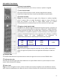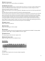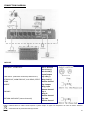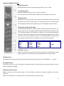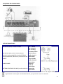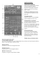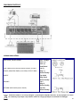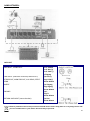
1
USB MIXER MX401 (15-2391) 4-CHANNEL MIXER MX801 (15-2392) 8-CHANNEL MIXER INSTRUCTION MANUAL MANUEL D’UTILISATION BEDIENUNGSANLEITUNG MANUAL DE INSTRUÇÕES GHID DE UTILIZARE INSTRUKCJA OBSŁUGI MANUAL DE INSTRUCCIONES NAVODILA ZA UPORABO 1 IMPORTANT SAFETY INSTRUCTIONS 1) Read the manual prior to using this unit and keep it for future reference. 2) Adhere to all warnings and instructions marked on the unit and contained in the manual. 3) Don’t place the unit close to water, e.g. in a bathroom, near a wash tub, a swimming pool, etc. 4) The unit must match carriage and rack recommended by the manufacturer. Sudden stops, great power and rough surface may cause combination turns over. 5) Keep away from heat sources such as radiator, stove and amplifier etc. 6) Operate the unit only with the rated power supply. Please ask your dealer or local power supply company if you are not sure about your type of power supply .If the unit is operated with batteries or 2 other power supplies, please refer to this booklet. 7) Connection to ground or polarization: If the unit is fitted with a polarized AC plug, there is only one method to insert the plug. This is a safety characteristic. 8) Do not walk on or squeeze the power cord. 9) Clean this unit with a soft cloth. Prevent water and/or other liquids to enter into the housing. 10) Unplug the power cord if the unit is not used for a long time or during a thunderstorm to prevent voltage surges to damage the inner circuitry. 11) Prevent objects and liquids to enter into unit. 12) If one of the following happens, refer to qualified service personnel: A) Power cord or plug a damaged; or B) An object or liquid has entered into the unit; or C) The unit has been exposed to rain ; or D) The unit doesn’t work; or E) The unit has fallen or doesn’t work normally. 13) Repair ---Do not attempt to repair the unit yourself. All repairs must be carried out by a qualified technician. The user is only allowed to perform manipulations, settings and controls specified in this manual. 14) Ventilation --- Do not cover the ventilation openings to prevent overheating of the unit. Do not place the unit on bed, blanket, sofa or similar soft surface. Do not place unit inside a bookcase, a closed cupboard, etc. 15) Accessories---Not use parts that hare not recommended by the manufacturer in order to avoid damage. 16) Auxiliary equipment ---Do not place this unit on unstable vehicle, shelf, tripod or table. It will cause serious harm to child or adult if the unit falls down. Please use the vehicle, shelf, tripod or table recommended by the manufacturer. 17) Spare parts---If the unit requires spare parts, use only spares recommended by the manufacturer and that are in all aspects identical to the original parts. . 18) Safety check---After repairing, repairer must test the unit for security. 3 CHANNEL CONTROL SECTION: ① MIC input jack Balanced XLR microphone input jacks (1: ground; 2: hot; 3: cold) ② LINE input jacks Balanced TRS phone jacks (T: hot; R: cold; S: Ground) You can connect either balanced or unbalanced Jack plugs to this socket. ③ GAIN control Adjustment of the input signal level. To get the best balance between the S/N ratio and the dynamic range, adjust the input signal level so that the PEAK indicator lights occasionally and briefly only on the highest input transients. ④ Equalizer (HIGH, MID & LOW) This 3-band EQ adjusts the channel’s high, mid and low frequency bands. The stereo channel has a 2-frequency band: HIGH & LOW. Setting the knob to the “▼” position produces a flat frequency response in the corresponding band. Turning the knob to the right boosts the corresponding frequency band, while turning to the left attenuates the band. The following table shows the EQ type, frequency and maximum cut/boost for each of the three bands. Band Type Frequency Max. Cut/Boost HIGH MID LOW Shelving Peaking Shelving 12kHz 2.5kHz 80Hz ± 15dB ⑤ EFFECT Control Adjusts the level of the signal sent from the channel to the EFFECT bus. Note that the signal level sent to the bus is also affected by the channel fader. ⑥ PAN control The PAN control determines the stereo positioning of the channel signal on the STEREO L & R buses. ⑦ PEAK indicator The peak level of the post –EQ signal is detected and the PEAK indicator light yellow when the level reaches 3dB below clipping. ⑧ Channel Fader Control Adjusts the level of the channel signal. Use these faders to adjust the balance between the various channels. NOTE: Set the faders for unused channels all the way down to minimize noise. 4 MASTER CONTROL SECTION: ① REC (output) / 2TR (input) (L, R) Jacks You can connect these RCA pin jacks to an external recorder such as an MD recorder to record the signal output from the MAIN OUT jacks. Connect 2TR to send the signal to MAIN. ② LINE input jacks (stereo channel) These are unbalanced phone jack type stereo line inputs. ③ PHONES Jacks Connect a pair of headphones to this stereo phone jack. There are 2x Jacks: A & B. ④ MAIN OUT (L, R) jacks These jacks send the mixer’s stereo output. E.g. you can connect these jacks to a power amplifier driving the main speaker. When you record the mixer’s stereo output using the MAIN OUT Master fader to control the level, you can also connect these jacks to the recording device. ⑤ Music Player This is a high sound quality music player. Insert the USB device containing the MP3, WMA music files into the USB port and play the music via the stereo channel (USB select switch). ⑥ (▮) ¾ (7/8) (▬) USB Select switch Stereo channel signal selector switch. ⑦ MAIN GRAPHIC EQUALIZER This 5-band EQ adjusts the sound signal from the MAIN OUT jack. The EQ cuts or boosts all frequency bands (100Hz / 400Hz / 1kHz / 3kHz / 8kHz) within the range of ±12dB. ⑧ Delay Control Adjusts the delay time of the internal effect unit. ⑨ REPEAT Control Adjusts the depth of the internal digital effects. 5 ⑩ EFFECT Fader Control Adjusts the signal level of internal effects to the MAIN bus. ⑪ PHANTOM +48V switch This switch toggles phantom power on and off. When the switch is on, the mixer supplies +48V phantom power to all channels that have XLR mic input jacks. Turn this switch to on when using one or more phantom-powered condenser microphones NOTE: When this switch is on, the mixer supplies DC +48V power to pin 2 and 3 of all XLR type MIC INPUT jacks. CAUTION: Be sure to leave this switch OFF if you don’t need phantom power. When turning the switch to ON, be sure that only condenser microphones are connected to the XLR input jacks. Devices other than condenser mics may be damaged if connected to the phantom power supply. Please note however that the switch may be left on when connecting to balanced dynamic microphones. To prevent damage to speakers, be sure to turn off power amplifiers (or powered speakers) before turning this switch on or off. We also recommend that you turn all output controls (stereo out, Master fader, GROUP 1-2 fader, GROUP 3-4 fader, etc) to their minimum settings before operating the switch to avoid the risk of loud noises that could cause hearing loss or device damage. ⑫ PHONES Control Adjusts output level of jacks (4). ⑬ 2TR IN (TAPE) Adjusts the input signal of TAPE to MAIN. ⑭ Level Meter This LED meter displays the level of the signal output from the MAIN and the PHONES. ⑮ POWER indicator This indicator lights when the mixer’s power is ON. ⑯ MAIN OUT Master Fader Adjusts the signal level sent to the MAIN OUT jack. REAR PANEL: ① POWER AC power input: Properly insert the power adaptor (supplied). ② Power switch 6 CONNECTION DIAGRAM: JACK LIST In & output jacks MIC INPUT, STEREO OUT Polarities Pin 1 : Ground Pin 2: Hot (+) Pin 3: Cold (-) input/output LINE INPUT (monaural channels) GROUP OUT, STEREO OUT, MONITOR OUT, AUX SEND, EFFECT SEND Tip: Hot (+) Ring: Cold (-) Sleeve: Ground INSERT Tip: Output Ring: Input Sleeve: Ground Tip: L Ring: R Sleeve: Ground Tip: Hot Sleeve: Ground PHONES RETURN LINE INPUT (stereo channels) Configuration Electric products must not be put into household waste. Please bring them to a recycling centre. Ask your local authorities or your dealer about the way to proceed. 7 . F Consignes de Sécurité Lire le mode d’emploi avant la première mise en service du produit. Conserver le mode d’emploi pour référence ultérieure. Suivez toutes les instructions imprimées sur l’appareil afin de garantir une utilisation correcte. NE PAS OUVRIR LE BOITIER. IL NE CONTIENT AUCUNE PIECE REMPLACABLE PAR L’UTILISATEUR. TOUTES LES REPARATIONS DOIVENT ETRE EFFECTUEES PAR UN TECHNICIEN QUALIFIE. L’éclair dans le triangle attire l’utilisateur sur la présence de tensions dangereuses non isolées à l’intérieur du boîtier qui sont d’une magnitude suffisante pour constituer un risque d’électrisation. Le point d’exclamation dans le triangle équilatéral attire l’attention de l’utilisateur sur des instructions et consignes importantes continues dans ce manuel. Afin d’éviter tout risque d’électrocution ou d’incendie, ne pas exposer l’appareil à la pluie et à l’humidité. Notes : Assurez-vous que les prises secteur sont conformes à la tension d’alimentation requise pour cet appareil. La tension secteur doit correspondre à celle indiquée au dos de l’appareil. Ne pas utiliser l’appareil si le cordon secteur est endommagé. Protéger l’appareil contre des éclaboussures. Ne pas placer un objet rempli de liquide sur l’appareil. Brancher l’appareil sur une prise secteur mise à la terre. Avertissements : Toute utilisation, manipulation ou modification autre que celles spécifiées dans ce manuel risque de vous exposer à des tensions dangereuses. Toute réparation doit être effectuée par un technicien qualifié Utilisez uniquement des pièces détachées qui sont en tous points conformes aux pièces d’origine. Note : Sélectionnez la tension qui correspond à votre tension secteur à l’aide du commutateur au dos de l’appareil. Assurez-vous que l’appareil est éteint et débranché du secteur avant de commuter le sélecteur de tension sur la tension requise. Nous déclinons toute responsabilité pour des dommages provenant d’une mauvaise installation, câblage ou utilisation due à la négligence ou à l’erreur de l’utilisateur. Notes Importantes: 1) Lire le mode d’emploi avant la première mise en service du produit. 2) Conservez ce mode d’emploi pour référence ultérieure. 3) Lisez les consignes de sécurité avant d’effectuer des branchements et mettre l’appareil en service. 4) Respectez toutes les consignes de sécurité et d’utilisation contenues dans le manuel. 5) Respectez toutes les consignes de sécurité pour éviter un incendie et/ou des chocs électriques. 8 6) Eau et humidité : Ne pas utiliser l’appareil à proximité d’eau, p.ex. près d’une baignoire, d’un lavabo. 7) Ne pas placer l’appareil sur un chariot, un support, un tabouret ou une table instable. L’appareil peut tomber et provoquer des blessures et des dommages. Utilisez l’appareil uniquement avec un chariot, support, tabouret ou table recommandé par le fabricant et vendu avec l’appareil. 8) Lorsque l’appareil est installé sur un support, déplacez-le avec précaution. Des arrêts soudains, une force excessive et des surfaces irrégulières peuvent provoquer une chute. 9) Si vous montez l’appareil sur un mur ou au plafond, suivez les instructions du fabricant et utilisez le matériel de montage recommandé par le fabricant. 10) Placer l’appareil loin des sources de chaleur telles que radiateurs, poêles et autres appareils 11) Placez l’appareil de façon à ne pas compromettre sa ventilation. Ne pas placer sur une surface molle qui risque de bloquer ses fentes de ventilation. 12) Passez le cordon secteur de telle façon qu’il ne peut pas être pincé ou écrasé, notamment à proximité de la sortie du cordon de l’appareil ou près de la prise secteur. 13) Débranchez l’appareil du secteur avant de le nettoyer. 14) Utilisez uniquement un chiffon doux et humide. Ne pas laisser de l’eau pénétrer dans l’appareil. 15) En cas de non-utilisation prolongée, débranchez l’appareil du secteur. 16) Faites vérifier l’appareil par un technicien qualifié si - le cordon ou la fiche secteur ont été endommagés, - des objets ou des liquides ont pénétrés dans l’appareil, - l’appareil a été exposé à la pluie ou tout autre liquide, - l’appareil ne fonctionne pas normalement ou présente un changement significatif dans son fonctionnement, - l’appareil est tombé et le boîtier a été endommagé. 17) Pour les réparations, assurez-vous qu’uniquement des pièces détachés homologuées par le fabricant ont été utilisés qui présentent exactement les mêmes caractéristiques techniques que les pièces d’origine. 18) Après chaque réparation, demandez au réparateur d’effectuer tous les tests de routine afin de s’assurer du bon fonctionnement de l’appareil. 9 REGLAGES D’UN CANAL: ① Fiche d’entrée MICRO Fiches XLR symétriques pour micro (1: masse; 2: positif; 3: négatif) ② Jack d’entrée LIGNE Jack stéréo 6,35mm (Pointe: Positif, Anneau: Négatif Gaine: Masse) Cette fiche accepte aussi bien les jacks symétriques qu’asymétriques. ③ Contrôle de GAIN Réglage du niveau d’entrée du signal. Afin d’obtenir le meilleur équilibre entre le rapport S/B et la plage dynamique, réglez le niveau d’entrée du signal de manière à ce que le voyant PEAK (crête) ne s’allume occasionnellement et brièvement que lors des transitoires les plus aigus. ④ Egaliseur (HIGH, MID & LOW) Cet égaliseur à 3 bandes règle les bandes de fréquences graves, moyennes et aigues. Le canal stéréo possède une bande à 2 fréquences : GRAVES & AIGUS. Lorsque le bouton est réglé sur la positon “▼”, la réponse en fréquence n’est pas modifiée sur la bande en question. Tournez le bouton vers la droite pour renforcer la bande de fréquence ou vers la gauche pour l’atténuer. Le tableau ci-dessous monte le type d’égalisation, la fréquence et l’amplification/atténuation maximale pour chacune des 3 bandes. Bande Type Fréquence Max. Cut/Boost HIGH MID LOW Atténuation Peaking Atténuation 12kHz 2.5kHz 80Hz ± 15dB ⑤ Contrôle d’EFFET Règle le niveau du signal envoyé du canal dans le bus d’effets. Notez que le niveau du signal envoyé dans le bus est également affecté par le fader du canal. ⑥ Contrôle PAN Le contrôle PAN détermine le positionnement stéréo du signal du canal sur les bus STEREO G & D. ⑦ Indicateur de crête Le niveau de crête du signal post-EQ est détecté et le voyant PEAK s’allume en jaune lorsque le niveau atteint 3dB en dessous du clipping. ⑧ Fader Canal Règle le niveau du signal du canal. Utilisez ces faders pour ajuster l’équilibre entre les différents canaux. NOTE: Baissez complètement les faders de tous les canaux inutilisés afin de minimiser les bruits parasites. 10 SECTION MASTER: ① Fiches REC & 2TR (G/D) Vous pouvez connecter les prises REC sur un enregistreur externe tel qu’un enregistreur MD pour enregistrer le signal qui sort des fiches MAIN OUT. Le signal qui est branché sur les fiches 2TR (entrée) est envoyé vers la sortie MAIN. ② Fiches d’entrée LIGNE (canal stéréo) Il s’agit d’entrées stéréo de ligne de type Jack asymétrique. ③ Fiches PHONES Vous pouvez brancher 2 casques stéréo sur les fiches A & B. ④ Sortie principale (G/D) MAIN OUT Le signal stéréo de la table de mixage sort par ces fiches. Vous pouvez les connecter sur un amplificateur de puissance qui est relié aux enceintes. Si vous enregistrez la sortie stéréo en utilisant le fader général MAIN OUT pour régler le niveau, vous pouvez brancher ces fiches également sur un enregistreur. ⑤ Lecteur USB Branchez une clé USB contenant les fichiers MP3 ou WMA sur ce port USB et écoutez la musique dans un des canaux stéréo (Sélecteur USB). ⑥ (▮) ¾ (7/8) (▬) Sélecteur USB Sélectionne le canal stéréo pour la musique sur la clé USB. ⑦ EGALISEUR GRAPHIQUE PRINCIPAL Cet égaliseur à 5 bandes règle le signal en provenance de la fiche MAIN OUT. L’égaliseur atténue ou amplifie toutes les bandes de fréquences (100Hz / 400Hz / 1kHz / 3kHz / 8kHz) sur une plage de ±12dB. ⑧ Temporisation (Delay) Règle la temporisation du processeur d’effet interne. ⑨ REPETITION Règle la profondeur des effets numériques internes. ⑩ Contrôle Fader des Effets Règle le niveau de signal des effets internes vers le bus principal. ⑪ Commutateur d’alimentation fantôme +48V Ce commutateur active et désactive l’alimentation fantôme. Lorsque le commutateur est sur ON, la table de mixage envoie +48V à tous les canaux équipés de fiches micro XLR. Mettez ce commutateur sur ON si vous utilisez un ou plusieurs microphones à condensateur qui nécessitent une alimentation fantôme. 11 NOTE: Lorsque ce commutateur est sur ON, les broches 2 et 3 de toutes les entrées micro de type XLR sont alimentées en +48Vdc. ATTENTION: Laissez ce commutateur en position OFF (éteint) si vous n’avez pas besoin d’une alimentation fantôme. Lorsque vous mettez le commutateur sur ON, assurez-vous que seuls des microphones à condensateur sont connectés sur les entrées XLR. Un microphone normal risque d’être endommagé lorsqu’il est branché sur une alimentation fantôme. Notez toutefois que le commutateur peut être place sur ON lorsque des microphones dynamiques symétriques sont branchés. Afin d’éviter d’endommager les haut-parleurs, éteignez les amplificateurs de puissance (ou les enceintes actives) avant de mettre ce commutateur sur ON ou OFF. Il est également recommandé de baisser complètement tous les contrôles de sortie (sortie stéréo, fader général, faders du groupe 1-2, faders du groupe 3-4, etc.) avant d’actionner ce commutateur pour éviter le risqué de bruits puissants qui peuvent endommager l’ouïe ou l’équipement. ⑫ Réglage PHONES Règle le niveau de sortie des fiches (4). ⑬ 2TR IN (TAPE) Règle le signal d’entrée de TAPE vers MAIN. ⑭ Echelle à LED Ce vumètre à LED affiche le niveau du signal des sorties MAIN et PHONES. ⑮ Voyant POWER Ce voyant s’allume lorsque la table de mixage est sous tension. ⑯ Fader general MAIN OUT Règle le niveau du signal qui est envoyé à la fiche MAIN OUT. ARRIERE: ① Alimentation Fiche d’alimentation AC: Branchez l’adaptateur secteur fourni. ② Interrupteur Marche/Arrêt 12 SCHEMA DE BRANCHEMENT: LISTE DES CONNECTEURS Entrées & Sorties ENTRÉE MICRO, SORTIE STEREO Polarités Pin 1 : Masse Pin 2: Hot (+) Pin 3: Cold (-) entrées/sortie ENTREE LIGNE (canaux mono) SORTIE GROUPE, SORTIE MONITOR, STEREO OUT, MONITOR OUT, AUX SEND, EFFECT SEND Pointe: Hot (+) Bague: Cold (-) Gaine: Masse INSERT Pointe: Sortie Bague: Entrée Gaine: Masse Pointe: G Bague: D Gaine: Masse Pointe: Hot Gaine: Masse PHONES RETURN LINE INPUT (stereo channels) Configuration NOTE IMPORTANTE : Les produits électriques ne doivent pas être mis au rebut avec les ordures ménagères. Veuillez les faire recycler là où il existe des centres pour cela. Consultez les autorités locales ou votre revendeur sur la façon de les recycler. 13 D Sicherheitshinweise Bitte lesen Sie diese Anleitung sorgfältig vor der Inbetriebnahme durch. Anleitung für spätere Bezugnahme aufbewahren. Alle Warnhinweise auf dem Gerät und in der Anleitung genau befolgen. NICHT DAS GEHÄUSE ÖFFNEN. ES BESTEHT STROMSCHLAG- UND FEUERGEFAHR. DAS GEHÄUSE ENTHÄLT KEINE VOM BENUTZER AUSWECHELBAREN TEILE. REPARATUREN NUR VON EINEM FACHMANN AUSFÜHREN LASSEN Der Blitz im Dreieck lenkt die Aufmerksamkeit des Benutzers auf unisolierte gefährliche Spannungen im Gehäuseinneren hin, die einen Stromschlag verursachen können. Das Ausrufezeichen im Dreieck lenkt die Aufmerksamkeit des Benutzers auf wichtige Hinweise und Anweisungen in der Anleitung hin. Um Stromschlag und Feuer zu vermeiden, das Gerät vor Regen und Feuchtigkeit schützen. Hinweise: Die Netzsteckdosen müssen der benötigten Versorgungsspannung entsprechen. Die Netzspannung muss der auf der Rückseite des Geräts angegebenen Spannung entsprechen. Das Gerät nicht benutzen, wenn das Netzkabel beschädigt ist. Das Gerät vor Spritzwasser schützen. Keine mit Wasser gefüllten Gegenstände wie Vasen, Flaschen usw. aufs Gerät stellen. Nur an eine geerdete Netzsteckdose anschließen. Warnhinweise: Einstellungen, Bedienvorgänge oder Veränderungen, die nicht ausdrücklich in der Anleitung beschrieben worden sind, können gefährliche Strahlungen verursachen. Reparaturen dürfen nur von einem Fachmann vorgenommen werden Nur Ersatzteile benutzen, die in jeder Hinsicht mit dem Originalteil identisch sind. Hinweis: Wählen Sie die Spannung, die Ihrer Netzspannung entspricht mittels des Spannungswahlschalters auf der Rückseite des Geräts. Das Gerät muss ausgeschaltet und vom Netz getrennt sein, bevor Sie den Spannungswahlschalter auf die benötigte Spannung einstellen. Wir übernehmen keine Haftung für Schäden, die durch falsche Installation, falsche Anschlüsse oder 14 unsachgemäßen Gebrauch, durch die Nachlässigkeit oder Irrtum des Benutzers entstanden sind. Wichtige Hinweise: 1) Bitte lesen Sie diese Anleitung sorgfältig vor der Inbetriebnahme durch. Anleitung für spätere Bezugnahme aufbewahren. 2) Alle Warnhinweise auf dem Gerät und in der Anleitung genau befolgen. 3) Behandeln Sie die Netzschnur mit Sorgfalt und beschädigen oder verformen Sie sie nicht. Eine beschädigte oder verformte Netzschnur kann Stromschlag und Defekte verursachen. Beim Abziehen des Steckers aus der Steckdose immer am Stecker anfassen, nie an der Schnur ziehen. 4) Keine Metallgegenstände oder Flüssigkeiten ins Gehäuse dringen lassen. Sie können zu Stromschlag und Störungen führen. 5) Das Gerät niemals auf einen unsicheren Wagen, Ständer oder Tisch stellen. Das Gerät kann herunterfallen und Menschen verletzen. Nur mit einem vom Hersteller zugelassenen oder mit dem Gerät zusammen verkauften Wagen, Stativ oder Tisch benutzen 6) Beim Anbringen des Geräts an der Decke oder Wand die Anweisungen des Herstellers befolgen und die vom Hersteller empfohlenen Montagematerialien benutzen. 7) Wenn das Gerät auf einem Gestell steht, das Ganze vorsichtig bewegen. Plötzliches Bremsen, große Kraftanwendung und unebene Flächen können zum Umkippen führen. 8) Das Gerät nicht in der Nähe von Wasser benutzen z.B. neben einer Badewanne, Spüle, Waschmaschine. 9) Nicht die Belüftung behindern. Nicht auf ein Sofa, Bett, Sessel oder ähnliche weiche Unterlagen stellen. Nicht in ein geschlossenes Gehäuse wie einen Schrank einbauen, wo die Hitze nicht abgeleitet werden kann. 10) Das Gerät nicht in der Nähe von Wärmequellen wie Heizkörpern, Öfen und ähnlichen Geräten aufstellen. 11) Nicht das Netzkabel betreten oder quetschen. 12) Vor dem Reinigen den Netzstecker abziehen. 13) Das Gerät nur mit einem feuchten Tuch abwischen. Kein Wasser ins Gehäuse dringen lassen. 14) Bei längerem Nichtgebrauch den Netzstecker abziehen. 15) Das Gerät muss von einem Techniker überprüft werden, wenn: das Netzkabel oder die –schnur beschädigt sind; das Gerät Regen oder anderen Flüssigkeiten ausgesetzt war; das Gerät nicht richtig funktioniert oder eine beachtliche Leistungsänderung aufweist; das Gerät gefallen oder das Gehäuse beschädigt ist. REPARATUREN DÜRFEN NUR VON QUALIFIZIERTEM FACHPERSONAL AUSGEFÜHRT WERDEN. Nach Abschluss der Wartungs- und Reparaturarbeiten lassen Sie alle Routineüberprüfungen durchführen, um die Sicherheit des Geräts zu gewährleisten. 15 KANALREGLER: ① Mikrofoneingangsbuchse Symmetrischer XLR Mikrofoneingang (1: Masse; 2: positiv; 3: negativ) ② LINE Eingang Symmetrische Stereo-Klinkenbuchse (Spitze: positiv; R: negativ; Mantel: Masse) Die Buchse eignet sich für symmetrische und asymmetrische Klinkenstecker. ③ GAIN Regler Einstellung des Eingangssignalpegels. Um das beste Verhältnis zwischen dem Signal/Rauschfaktor und dem dynamischen Bereich zu erreichen, muss der Eingangssignalpegel so eingestellt werden, dass der PEAK Anzeiger nur ab und zu kurz während der höchsten Transienten aufleuchtet. ④ Equalizer (HIGH, MID & LOW) Der 3-Band EQ regelt den hohen, mittleren und tiefen Frequenzbereich. Der Stereokanal besitzt einen 2-Band EQ: HIGH & LOW. Wenn der Regler auf “▼” steht, bleibt die Frequenz unverändert. Regler nach rechts drehen, um das entsprechende Frequenzband zu verstärken, bzw. nach links, um das Frequenzband abzuschwächen. Die folgende Tabelle zeigt den EQ Typ, die Frequenz und den Regelbereich für jedes Band an. Band Typ Frequenz Max. Cut/Boost HIGH MID LOW Shelving Peaking Shelving 12kHz 2.5kHz 80Hz ± 15dB ⑤ EFFECT Regler Stellt den Pegel des Signals ein, das vom Kanal in den EFFECT Bus geschleift wird. Bitte beachten, dass der Signalpegel zum Bus ebenfalls vom Kanalfader beeinflusst wird. ⑥ PAN Regler Der PAN Regler bestimmt die Stereostellung des Kanalsignals in den L & R STEREO Bussen. ⑦ PEAK Anzeiger Wenn der Spitzenpegel des Post-EQ Signals 3dB unter Clipping erreicht, leuchtet die PEAK Anzeige gelb auf. ⑧ Kanalfaderregler Stellt den Pegel des Kanalsignals ein. Mit diesen Fadern wird das Gleichgewicht unter den verschiedenen Kanälen eingestellt. HINWEIS: Die Fader aller unbenutzten Kanäle ganz herunterfahren, um Störgeräusche zu vermeiden. 16 MASTER BEDIENFELD: ① REC & 2TR (L, R) Buchsen Die REC Cinch-Buchsen dienen zum Anschluss an einen externen Recorder wie z.B. ein MD Recorder, um das Ausgangssignal von den MAIN OUT Buchsen aufzunehmen. Das Signal, das an den 2TR Eingang angeschlossen wird, wird in den MAIN Ausgang geschleift. ② LINE Eingangsbuchsen (Stereokanal) Line-Eingänge über asymmetrische StereoKlinkenbuchsen. ③ Kopfhörerbuchsen 2 Buchsen für Stereo-Kopfhörer: A & B. ④ MAIN OUT (L, R) Buchsen Hier liegt die Stereo-Ausgangssumme des Mischpults an. Die Buchsen können an einen Leistungsverstärker oder Aktivboxen angeschlossen werden. Diese Buchsen können auch an ein Aufnahmegerät angeschlossen werden, wenn der Pegel des Stereoausgangs mit dem MAIN OUT Masterfader eingestellt wird. ⑤ USB Player Schließen Sie Ihr USB Gerät, das die MP3 bzw. WMA Musikdateien enthält, an diesen Port an und spielen Sie die Titel über einen der Stereokanäle ab (USB Wahlschalter). ⑥ (▮) ¾ (7/8) (▬) USB Wahlschalter Wahl des Eingangssignals: USB oder Kanal 3/4. ⑦ HAUPT-GRAPHIC EQUALIZER Dieser 5-Band EQ regelt das Audiosignal von den MAIN OUT Buchsen. Der EQ verstärkt/dämpft alle Frequenzbänder (100Hz / 400Hz / 1kHz / 3kHz / 8kHz) innerhalb eines Bereichs von ±12dB. ⑧ Delay Regler Regelt die Verzögerungsdauer des internen Effektgeräts. ⑨ REPEAT Regler Stellt die Tiefe der internen Digitaleffekte ein. 17 ⑩ EFFECT Fader Regler Stellt den Signalpegel der internen Effekte zum MAIN Bus ein. ⑪ PHANTOM +48V Schaltung Mit diesem Schalter wird die Phantomspeisung ein- und ausgeschaltet. Wenn die Phantomspeisung eingeschaltet ist, liegen an allen Kanälen mit XLR Mikrofonbuchsen +48V an. Stellen Sie diesen Schalter auf ON, wenn Sie ein oder mehrere Kondensatormikrofone mit Phantomspeisung angeschlossen haben. HINWEIS: Wenn der Schalter auf ON steht, liegen +48Vdc an Pin 2 & 3 aller XLR Mikrofonbuchsen an. ACHTUNG: Stellen Sie den Schalter auf OFF, wenn Sie keine Phantomspeisung benötigen. Bevor Sie den Schalter auf ON stellen, vergewissern Sie sich, dass nur Kondensatormikrofone an die XLR Eingangsbuchsen angeschlossen sind. Andere Mikrofone können Schaden nehmen, wenn sie an eine Phantomschaltung angeschlossen werden. Nur symmetrische, dynamische Mikrofone können Phantomspeisung vertragen. Zum Schutz der Lautsprecher ist es ratsam, alle Leistungsverstärker (oder Aktivboxen) auszuschalten, bevor Sie diesen Schalter benutzen. Es ist ebenfalls empfehlenswert, alle Ausgangsregler (Stereo Ausgänge, Masterfader, Fader der Gruppe 1-2, 3-4 usw.) ganz herunterzufahren, bevor Sie den Schalter betätigen, um plötzliche laute Geräusche zu verhindern, die Gehör- und Materialschäden verursachen können. ⑫ PHONES Regler Stellt den Ausgangspegel der Buchsen (4) ein. ⑬ 2TR IN (TAPE) Stellt das Eingangssignal von TAPE nach MAIN ein. ⑭ LED Leiter Diese LED Leiter zeigt den Signalpegel vom MAIN und vom PHONES Ausgang an. ⑮ Betriebsanzeige Sie leuchtet, wenn das Mischpult in Betrieb ist. ⑯ MAIN OUT Master Fader Stellt den Signalpegel ein, der in die MAIN OUT Buchse geschleift wird. RÜCKSEITE: ① POWER AC Netzanschluss: Zum Anschluss des mitgelieferten Netzteils. ② Betriebsschalter 18 ANSCHLUSSSCHEMA: VERBINDER Ein- & Ausgangsverbinder MIKROFONEINGANG, STEREO AUSGANG Polarität Pin 1 : Masse Pin 2: Positiv (+) Pin 3: Negativ (-) Ein-/Ausgang LINE EINGANG (monaurale Kanäle) GROUP OUT, STEREO OUT, MONITOR OUT, AUX SEND, EFFECT SEND Spitze: Positiv (+) Ring: Negativ (-) Hülse: Masse INSERT Spitze: Ausgang Ring: Eingang Hülse: Masse Spitze: L Ring: R Hülse: Masse Spitze: Positiv Hülse: Masse PHONES RETURN LINE INPUT (stereo channels) Konfiguration WICHTIGER HINWEIS: Elektrogeräte gehören nicht in den Hausmüll. Sie müssen in speziellen Betrieben recycelt werden. Bringen Sie sie zu einer speziellen Entsorgungsstelle für Elektrokleingeräte (Wertstoffhof)! 19 PT Instruções de Segurança Consulte as instruções antes de usar o equipamento. Guarde este manual para referência futura. Siga todas as instruções para um funcionamento adequado. De modo a evitar o risco de choque eléctrico ou fogo, não abra o equipamento. Não existem peças suplentes na embalagem. Apenas profissionais qualificados devem proceder a operações de reparação. Este símbolo é usado para alertar para a presença de instruções importantes sobre o funcionamento da unidade. Este símbolo é usado para alertar sobre o perigo de voltagens perigosas presentes nos produtos, pois existe o perigo de electrocussão. Aviso: De modo a evitar o risco de choque eléctrico, não exponha o equipamento a chuva ou humidade. Notas: • Certifique-se de que as tomadas existentes estão em conformidade com as voltagens requeridas no painel traseiro do equipamento. • • Não use o equipamento se o cabo de alimentação estiver danificado. Não pode expor a unidade a chuva ou humidade ou pousar objectos com líquidos em cima do equipamento. • A unidade devera estar ligada a uma tomada com ligação terra. Aviso: • Ajustar ou usar o programa de controlo para além do descrito nestas especificações pode causar radiações perigosas. • • A unidade só deve ser reparada por profissionais qualificados. Se a unidade estiver em reparação, só devem ser usadas partes com as mesmas especificações. Notas: • Certifique-se de que a unidade está desligada da corrente antes de efectuar reparações. Não nos responsabilizamos por danos causados resultantes de negligência na instalação, ligação ou operação do equipamento. • Seleccione a voltagem correcta no interruptor de voltagem no painel traseiro. 20 INSTRUÇÕES DE SEGURANÇA 1) Leia o manual antes de usar este aparelho e guarde-o para futura referência. 2) Respeite todos os avisos e instruções contidos na unidade e no manual. 3) Não coloque o aparelho perto da água 4) A unidade deve respeitar o transporte e rack recomendados pelo fabricante. Paragens bruscas, grandes velocidades e superfícies rígidas podem causar danos. 5) Manter longe de fontes de calor 6) O aparelho só funciona com a fonte de alimentação recomendada. Consulte o seu revendedor ou a companhia de abastecimento local de energia, se não tiver a certeza sobre o tipo de voltagem na sua residência. Se a unidade for operada com baterias ou outras fontes de alimentação, consulte este folheto. 7) Ligação terra ou polarização: Se a unidade está equipada com uma ficha AC polarizada existe apenas um método para inserir a ficha. Esta é uma característica de segurança. 8) Não pise ou apertar o cabo de alimentação. 9) Limpe o aparelho com um pano macio. Evitar que a água e outros líquidos entrem na unidade. 10) Desligue o cabo de alimentação se o aparelho não for utilizado por um longo período de tempo ou durante uma tempestade de modo evitar picos de energia que podem danificar o circuito interno. 11) Evitar que objectos e líquidos entrem na unidade. 12) Se uma das seguintes opções acontecer, consulte profissionais qualificados: A) O cabo de alimentação ou a ficha estão danificados; B) Um objecto ou líquido entrou para a unidade, ou C) A unidade tem sido exposto à chuva, ou D) A unidade não funciona, ou E) O aparelho tenha caído ou não funciona normalmente. 13) Reparação --- Não tente reparar o aparelho. Todas as reparações devem ser realizadas por um técnico qualificado. O utilizador só tem permissão para executar operações, configurações e controlos especificados neste manual. 14) Ventilação --- Não cubra as aberturas de ventilação de modo a evitar o sobreaquecimento do aparelho. Não coloque a unidade numa cama, cobertor, sofá ou superfície macia similar. Não coloque a unidade dentro de uma estante, um armário fechado, etc 15) Acessórios --- Não use peças que não sejam recomendado pelo fabricante, de modo a evitar danos. 16) O equipamento auxiliar --- Não coloque esta unidade sobre veículos instáveis, tais como, prateleira, tripé ou mesa. Poderá perigoso para uma criança ou adulto, se a unidade cair. Por favor use o veículo, prateleira, tripé ou mesa recomendados pelo fabricante. 17) Peças --- Se a unidade precisar de peças de substituição, utilize somente peças recomendadas pelo fabricante e que são em todos os aspectos idênticas as peças originais. 18) Teste de segurança --- Após a reparação, o técnico deve testar a unidade por questões de segurança. 21 CHANNEL CONTROL SECTION: ① MIC input jack Balanced XLR microphone input jacks (1: ground; 2: hot; 3: cold) ② LINE input jacks Balanced TRS phone jacks (T: hot; R: cold; S: Ground) You can connect either balanced or unbalanced Jack plugs to this socket. ③ GAIN control Adjustment of the input signal level. To get the best balance between the S/N ratio and the dynamic range, adjust the input signal level so that the PEAK indicator lights occasionally and briefly only on the highest input transients. ④ Equalizer (HIGH, MID & LOW) This 3-band EQ adjusts the channel’s high, mid and low frequency bands. The stereo channel has a 2-frequency band: HIGH & LOW. Setting the knob to the “▼” position produces a flat frequency response in the corresponding band. Turning the knob to the right boosts the corresponding frequency band, while turning to the left attenuates the band. The following table shows the EQ type, frequency and maximum cut/boost for each of the three bands. Band Type Frequency Max. Cut/Boost HIGH MID LOW Shelving Peaking Shelving 12kHz 2.5kHz 80Hz ± 15dB ⑤ EFFECT Control Adjusts the level of the signal sent from the channel to the EFFECT bus. Note that the signal level sent to the bus is also affected by the channel fader. ⑥ PAN control The PAN control determines the stereo positioning of the channel signal on the STEREO L & R buses. ⑦ PEAK indicator The peak level of the post –EQ signal is detected and the PEAK indicator light yellow when the level reaches 3dB below clipping. ⑧ Channel Fader Control Adjusts the level of the channel signal. Use these faders to adjust the balance between the various channels. NOTE: Set the faders for unused channels all the way down to minimize noise. 22 MASTER CONTROL SECTION: ① TAPE OUT IN (L, R) Jacks You can connect these RCA pin jacks to an external recorder such as an MD recorder to record the signal output from the MAIN OUT jacks. Connect IN to send the signal to MAIN. ② LINE input jacks (stereo channel) These are unbalanced phone jack type stereo line inputs. ③ PHONES Jacks Connect a pair of headphones to this stereo phone jack. There are 2x Jacks: A & B. ④ MAIN OUT (L, R) jacks These jacks send the mixer’s stereo output. E.g. you can connect these jacks to a power amplifier driving the main speaker. When you record the mixer’s stereo output using the MAIN OUT Master fader to control the level, you can also connect these jacks to the recording device. ⑤ Music Player This is a high sound quality music player. Insert the USB device containing the MP3, WMA music files into the USB port and play the music via the stereo channel (USB select switch). ⑥ (▮) ¾ (7/8) (▬) USB Select switch Stereo channel signal selector switch. ⑦ MAIN GRAPHIC EQUALIZER This 5-band EQ adjusts the sound signal from the MAIN OUT jack. The EQ cuts or boosts all frequency bands (100Hz / 400Hz / 1kHz / 3kHz / 8kHz) within the range of ±12dB. ⑧ Delay Control Adjusts the delay time of the internal effect unit. ⑨ REPEAT Control Adjusts the depth of the internal digital effects. 23 ⑩ EFFECT Fader Control Adjusts the signal level of internal effects to the MAIN bus. ⑪ PHANTOM +48V switch This switch toggles phantom power on and off. When the switch is on, the mixer supplies +48V phantom power to all channels that have XLR mic input jacks. Turn this switch to on when using one or more phantom-powered condenser microphones NOTE: When this switch is on, the mixer supplies DC +48V power to pin 2 and 3 of all XLR type MIC INPUT jacks. CAUTION: Be sure to leave this switch OFF if you don’t need phantom power. When turning the switch to ON, be sure that only condenser microphones are connected to the XLR input jacks. Devices other than condenser mics may be damaged if connected to the phantom power supply. Please note however that the switch may be left on when connecting to balanced dynamic microphones. To prevent damage to speakers, be sure to turn off power amplifiers (or powered speakers) before turning this switch on or off. We also recommend that you turn all output controls (stereo out, Master fader, GROUP 1-2 fader, GROUP 3-4 fader, etc) to their minimum settings before operating the switch to avoid the risk of loud noises that could cause hearing loss or device damage. ⑫ PHONES Control Adjusts output level of jacks (4). ⑬ 2TR IN (TAPE) Adjusts the input signal of TAPE to MAIN. ⑭ Level Meter This LED meter displays the level of the signal output from the MAIN and the PHONES. It displays MAIN level when it doesn’t light. It displays PHONES level when it lights. ⑮ POWER indicator This indicator lights when the mixer’s power is ON. ⑯ MAIN OUT Master Fader Adjusts the signal level sent to the MAIN OUT jack. REAR PANEL: ① POWER AC power input: Properly insert the power adaptor (supplied). ② Power switch 24 CONNECTION DIAGRAM: JACK LIST In & output jacks MIC INPUT, STEREO OUT Polarities Pin 1 : Ground Pin 2: Hot (+) Pin 3: Cold (-) input/output LINE INPUT (monaural channels) GROUP OUT, STEREO OUT, MONITOR OUT, AUX SEND, EFFECT SEND Tip: Hot (+) Ring: Cold (-) Sleeve: Ground INSERT Tip: Output Ring: Input Sleeve: Ground Tip: L Ring: R Sleeve: Ground Tip: Hot Sleeve: Ground PHONES RETURN LINE INPUT (stereo channels) Configuration Produtos eléctricos não deverão ser postos em contentores de lixo caseiros. Por favor, deposite-os em contentores para reciclagem. Questione as autoridades locais ou onde adquiriu o produto sobre como deverá proceder 25 RO PRECAUTII Cititi cu atentie manualul inainte de punerea in functiune a dispozitivului. Pastrati manualul pentru referinte ulterioare. Urmati toate instructiunile pentru a asigura o functionare corespunzatoare. • ATENTIE: Pentru a reduce riscul unui soc electric, nu indepartati capacul (sau partea din spate). Nu veti gasi componente utile in interior. Consultati doar personal calificat pentru service. Semnul exclamarii in interiorul unui triunghi indica prezenta unor instructiuni si avertismente de functionare prezentate in detaliu in manual. Triunghiul continand simbolul fulgerului si sageata va indica cazurile in care sanatatea dumneavoastra este in pericol (datorita electrocutarii, de exemplu). Avertisment: Pentru a reduce riscul unui incendiu sau al unui soc electric, feriti dispozitivul de umezeala. NOTE: • Asigurati-va ca tensiunea de la prizele de alimentare corespunde cerintelor inscrise pe partea din spate a aparatului. • • • Tensiunea retelei trebuie sa fie corecta si identica cu cea inscrisa pe partea din spate a aparatului. Nu utilizati aparatul in cazul in care cablul electric este uzat sau rupt. Aparatul trebuie ferit de picaturi sau stropiri cu apa iar obiecte umplute cu lichide, cum ar fi vazele, nu trebuie asezate pe aparat. • • Aparatul va fi conectat la o priza de retea avand conexiune cu pamantare. Cablul de alimentare trebuie sa fie usor de actionat (sa se poata scoate usor din priza in caz de urgenta). AVERTISMENT: • Folosirea, reglarea sau schimbarea controlului asupra programului in afara acestor specificatii poate duce la radiatii periculoase. • • Aparatul trebuie intretinut de personalul calificat. In caz de reparatii, folositi doar componente cu aceleasi specificatii. NOTE: • Selectati cerintele referitoare la tensiune cu ajutorul comutatorului de selectare a tensiunii de pe panoul din spate. • Asigurati-va ca echipamentul este oprit si deconectati de la retea inainte de pozitionarea selectorului de tensiune pe setarea solicitata. Nu suntem responsabili pentru pagubele rezultate din instalarea necorespunzatoare, legarea incorecta a cablurilor sau functionarea defectuoasa din cauza sau neglijenta utilizatorului. 26 INSTRUCTIUNI IMPORTANTE PRIVIND FUNCTIONAREA IN SIGURANTA 1) Cititi manualul inainte de a folosi aparatul si pastrati-l pentru referinte ulterioare. 2) Trebuie sa respectati toate avertismentele si instructiunile inscrise pe aparat si cele continute in manual. 3) Nu asezati aparatul in apropierea unei surse de apa, ex: intr-o baie, in apropierea unei cazi de baie, unei piscine, etc. 4) In caz de transport, aparatul trebuie sa se potriveasca caruciorului pentru transport si suportului recomandat de producator. Opririle bruste şi suprafaţele dure pot cauza rasturnari ale aparatului. 5) Pastrati departe de surse de caldura cum ar fi radiatoare, cuptor, amplificator etc. 6) Actionati aparatul doar cu sursa de alimentare recomandata. Va rugam sa consultati furnizorul sau compania de energie electrica locala in cazul in care aveti indoieli cu privire la tipul parametrii retelei de curent. In cazul in care aparatul functioneaza cu baterii sau alte surse de alimentare, va rugam sa consultati acest manual. 7) Conexiunea la masa sau polarizarea: in cazul in care aparatul este echipat cu o mufa AC polarizata, exista o singura modalitate de a introduce mufa. Aceasta este o caracteristica de siguranta 8) Nu calcati si nu strangeti cablul de alimentare. 9) Curatati aparatul cu un material moale. Nu lasati apa si/sau alte lichide sa patrunda in interiorul carcasei. 10) Deconectati cablul de alimentare in cazul in care aparatul nu este folosit o perioada indelungata de timp sau in timpul unei furtuni pentru a preveni ca supratensiunile sa deterioreze circuitele interne. 11) Preveniti patrunderea obiectelor si substantelor lichide in interiorul aparatului. 12) In cazul in care unul dintre cazurile de mai jos pot sa apara, consultati personalul calificat: a. Cablul de alimentare sau mufa sunt deteriorate sau b. Un obiect sau o substanta lichida au intrat in aparat sau c. Aparatul a fost expus umezelii sau d. Aparatul nu functioneaza sau e. Aparatul a cazut sau nu functioneaza corespunzator. 13) Reparatii ---Nu incercati sa reparati aparatul. Orice fel de reparatii trebuie sa fie efectuate de catre un tehnician calificat. Utilizatorului ii este permis sa efectueze doar setarile, manipularea si comenzile specificate in acest manual. 14) Ventilatia --- Nu acoperiti orificiile de ventilatie pentru a preveni astfel supraincalzirea aparatului. Nu asezati aparatul pe pat, patura, canapea sau suprafete similare. Nu asezati aparatul in interiorul unei biblioteci, unui dulap inchis, etc. 15) Accesorii---Nu folositi componente care nu sunt recomandate de producator pentru a evita in acest fel deteriorarea aparatului. 16) Echipament auxiliar --- Nu amplasati aparatul intr-un mijloc de transport instabil, pe un raft, trepied sau pe o masa. Caderea aparatului poate cauza leziuni grave copiilor sau adultilor. Va rugam sa folositi vehiculul, raftul, trepiedul sau masa recomandate de catre producator. 17) Piese de schimb---In cazul in care aparatul necesita piese de schimb, folositi doar acele piese care au fost recomandate de catre producator si care sa fie identice pieselor originale din toate punctele de vedere. 18) Verificare de siguranta---Dupa efectuarea reparatiei, aparatul trebuie testat. 27 CHANNEL CONTROL SECTION: ① MIC input jack Balanced XLR microphone input jacks (1: ground; 2: hot; 3: cold) ② LINE input jacks Balanced TRS phone jacks (T: hot; R: cold; S: Ground) You can connect either balanced or unbalanced Jack plugs to this socket. ③ GAIN control Adjustment of the input signal level. To get the best balance between the S/N ratio and the dynamic range, adjust the input signal level so that the PEAK indicator lights occasionally and briefly only on the highest input transients. ④ Equalizer (HIGH, MID & LOW) This 3-band EQ adjusts the channel’s high, mid and low frequency bands. The stereo channel has a 2-frequency band: HIGH & LOW. Setting the knob to the “▼” position produces a flat frequency response in the corresponding band. Turning the knob to the right boosts the corresponding frequency band, while turning to the left attenuates the band. The following table shows the EQ type, frequency and maximum cut/boost for each of the three bands. Band Type Frequency Max. Cut/Boost HIGH MID LOW Shelving Peaking Shelving 12kHz 2.5kHz 80Hz ± 15dB ⑤ EFFECT Control Adjusts the level of the signal sent from the channel to the EFFECT bus. Note that the signal level sent to the bus is also affected by the channel fader. ⑥ PAN control The PAN control determines the stereo positioning of the channel signal on the STEREO L & R buses. ⑦ PEAK indicator The peak level of the post –EQ signal is detected and the PEAK indicator light yellow when the level reaches 3dB below clipping. ⑧ Channel Fader Control Adjusts the level of the channel signal. Use these faders to adjust the balance between the various channels. NOTE: Set the faders for unused channels all the way down to minimize noise. 28 MASTER CONTROL SECTION: ① TAPE OUT IN (L, R) Jacks You can connect these RCA pin jacks to an external recorder such as an MD recorder to record the signal output from the MAIN OUT jacks. Connect IN to send the signal to MAIN. ② LINE input jacks (stereo channel) These are unbalanced phone jack type stereo line inputs. ③ PHONES Jacks Connect a pair of headphones to this stereo phone jack. There are 2x Jacks: A & B. ④ MAIN OUT (L, R) jacks These jacks send the mixer’s stereo output. E.g. you can connect these jacks to a power amplifier driving the main speaker. When you record the mixer’s stereo output using the MAIN OUT Master fader to control the level, you can also connect these jacks to the recording device. ⑤ Music Player This is a high sound quality music player. Insert the USB device containing the MP3, WMA music files into the USB port and play the music via the stereo channel (USB select switch). ⑥ (▮) ¾ (7/8) (▬) USB Select switch Stereo channel signal selector switch. ⑦ MAIN GRAPHIC EQUALIZER This 5-band EQ adjusts the sound signal from the MAIN OUT jack. The EQ cuts or boosts all frequency bands (100Hz / 400Hz / 1kHz / 3kHz / 8kHz) within the range of ±12dB. ⑧ Delay Control Adjusts the delay time of the internal effect unit. ⑨ REPEAT Control Adjusts the depth of the internal digital effects. 29 ⑩ EFFECT Fader Control Adjusts the signal level of internal effects to the MAIN bus. ⑪ PHANTOM +48V switch This switch toggles phantom power on and off. When the switch is on, the mixer supplies +48V phantom power to all channels that have XLR mic input jacks. Turn this switch to on when using one or more phantom-powered condenser microphones NOTE: When this switch is on, the mixer supplies DC +48V power to pin 2 and 3 of all XLR type MIC INPUT jacks. CAUTION: Be sure to leave this switch OFF if you don’t need phantom power. When turning the switch to ON, be sure that only condenser microphones are connected to the XLR input jacks. Devices other than condenser mics may be damaged if connected to the phantom power supply. Please note however that the switch may be left on when connecting to balanced dynamic microphones. To prevent damage to speakers, be sure to turn off power amplifiers (or powered speakers) before turning this switch on or off. We also recommend that you turn all output controls (stereo out, Master fader, GROUP 1-2 fader, GROUP 3-4 fader, etc) to their minimum settings before operating the switch to avoid the risk of loud noises that could cause hearing loss or device damage. ⑫ PHONES Control Adjusts output level of jacks (4). ⑬ 2TR IN (TAPE) Adjusts the input signal of TAPE to MAIN. ⑭ Level Meter This LED meter displays the level of the signal output from the MAIN and the PHONES. It displays MAIN level when it doesn’t light. It displays PHONES level when it lights. ⑮ POWER indicator This indicator lights when the mixer’s power is ON. ⑯ MAIN OUT Master Fader Adjusts the signal level sent to the MAIN OUT jack. REAR PANEL: ① POWER AC power input: Properly insert the power adaptor (supplied). ② Power switch 30 CONNECTION DIAGRAM: JACK LIST In & output jacks MIC INPUT, STEREO OUT Polarities Pin 1 : Ground Pin 2: Hot (+) Pin 3: Cold (-) input/output LINE INPUT (monaural channels) GROUP OUT, STEREO OUT, MONITOR OUT, AUX SEND, EFFECT SEND Tip: Hot (+) Ring: Cold (-) Sleeve: Ground INSERT Tip: Output Ring: Input Sleeve: Ground Tip: L Ring: R Sleeve: Ground Tip: Hot Sleeve: Ground PHONES RETURN LINE INPUT (stereo channels) Configuration Produsele electrice nu trebuie reciclate impreuna cu gunoiul menajer. Va rugam sa le transportati la un centru de reciclare. Adresati-va autoritatilor locale sau furnizorului local despre procedura. 31 PL Zasady bezpieczeństwa: Należy przestrzegać wszystkich warunków użytkowania i konserwacji urządzenia zawartych w niniejszym dokumencie Przeczytaj poniższą instrukcje obsługi przed pierwszym uruchomieniem urządzenia i zachowaj ją na by w przyszłości móc do niej wrócić gdy zaistnieje taka potrzeba Tylko wykwalifikowany personel może dokonywać napraw i konserwancji urządzenia. Pierwsze uruchomienie: 1)upewnij się, że kabel zasilający jest prawidłowo zamocowany w gnieździe urządzeniach 2)napięcie w gnieździe zasilania musi być takie samo jak w specyfikacji urządzenia 3)nie włączaj urządzenia jeśli zauważysz uszkodzenie kabla zasilającego 4)urządzenie nie może być narażone na bezpośrednie działanie warunków atmosferycznych, należy je chronić przed zalaniem oraz wilgocią 5)urządzenie powinno być podłączone do gniazda zasilania z uziemieniem Uwaga: Użycie urządzenia w sposób inny niż opisany w instrukcji obsługi może skutkować jego uszkodzeniem lub zniszczeniem Serwis urządzenia może przeprowadzić tylko wykwalifikowany personel. Zadbaj, by podczas napraw i konserwacji były używane części pochodzące z autoryzowanego serwisu marki 32 CHANNEL CONTROL SECTION: ① MIC input jack Balanced XLR microphone input jacks (1: ground; 2: hot; 3: cold) ② LINE input jacks Balanced TRS phone jacks (T: hot; R: cold; S: Ground) You can connect either balanced or unbalanced Jack plugs to this socket. ③ GAIN control Adjustment of the input signal level. To get the best balance between the S/N ratio and the dynamic range, adjust the input signal level so that the PEAK indicator lights occasionally and briefly only on the highest input transients. ④ Equalizer (HIGH, MID & LOW) This 3-band EQ adjusts the channel’s high, mid and low frequency bands. The stereo channel has a 2-frequency band: HIGH & LOW. Setting the knob to the “▼” position produces a flat frequency response in the corresponding band. Turning the knob to the right boosts the corresponding frequency band, while turning to the left attenuates the band. The following table shows the EQ type, frequency and maximum cut/boost for each of the three bands. Band HIGH MID LOW Type Shelving Peaking Shelving Frequency 12kHz 2.5kHz 80Hz Max. Cut/Boost ± 15dB ⑤ EFFECT Control Adjusts the level of the signal sent from the channel to the EFFECT bus. Note that the signal level sent to the bus is also affected by the channel fader. ⑥ PAN control The PAN control determines the stereo positioning of the channel signal on the STEREO L & R buses. ⑦ PEAK indicator The peak level of the post –EQ signal is detected and the PEAK indicator light yellow when the level reaches 3dB below clipping. ⑧ Channel Fader Control Adjusts the level of the channel signal. Use these faders to adjust the balance between the various channels. NOTE: Set the faders for unused channels all the way down to minimize noise. 33 MASTER CONTROL SECTION: ① TAPE OUT IN (L, R) Jacks You can connect these RCA pin jacks to an external recorder such as an MD recorder to record the signal output from the MAIN OUT jacks. Connect IN to send the signal to MAIN. ② LINE input jacks (stereo channel) These are unbalanced phone jack type stereo line inputs. ③ PHONES Jacks Connect a pair of headphones to this stereo phone jack. There are 2x Jacks: A & B. ④ MAIN OUT (L, R) jacks These jacks send the mixer’s stereo output. E.g. you can connect these jacks to a power amplifier driving the main speaker. When you record the mixer’s stereo output using the MAIN OUT Master fader to control the level, you can also connect these jacks to the recording device. ⑤ Music Player This is a high sound quality music player. Insert the USB device containing the MP3, WMA music files into the USB port and play the music via the stereo channel (USB select switch). ⑥ (▮) ¾ (7/8) (▬) USB Select switch Stereo channel signal selector switch. ⑦ MAIN GRAPHIC EQUALIZER This 5-band EQ adjusts the sound signal from the MAIN OUT jack. The EQ cuts or boosts all frequency bands (100Hz / 400Hz / 1kHz / 3kHz / 8kHz) within the range of ±12dB. ⑧ Delay Control Adjusts the delay time of the internal effect unit. ⑨ REPEAT Control Adjusts the depth of the internal digital effects. ⑩ EFFECT Fader Control Adjusts the signal level of internal effects to the MAIN bus. ⑪ PHANTOM +48V switch 34 This switch toggles phantom power on and off. When the switch is on, the mixer supplies +48V phantom power to all channels that have XLR mic input jacks. Turn this switch to on when using one or more phantom-powered condenser microphones NOTE: When this switch is on, the mixer supplies DC +48V power to pin 2 and 3 of all XLR type MIC INPUT jacks. CAUTION: Be sure to leave this switch OFF if you don’t need phantom power. When turning the switch to ON, be sure that only condenser microphones are connected to the XLR input jacks. Devices other than condenser mics may be damaged if connected to the phantom power supply. Please note however that the switch may be left on when connecting to balanced dynamic microphones. To prevent damage to speakers, be sure to turn off power amplifiers (or powered speakers) before turning this switch on or off. We also recommend that you turn all output controls (stereo out, Master fader, GROUP 1-2 fader, GROUP 3-4 fader, etc) to their minimum settings before operating the switch to avoid the risk of loud noises that could cause hearing loss or device damage. ⑫ PHONES Control Adjusts output level of jacks (4). ⑬ 2TR IN (TAPE) Adjusts the input signal of TAPE to main. ⑭ Level Meter This LED meter displays the level of the signal output from the MAIN and the PHONES. It displays MAIN level when it doesn’t light. It displays PHONES level when it lights. ⑮ POWER indicator This indicator lights when the mixer’s power is ON. ⑯ MAIN OUT Master Fader Adjusts the signal level sent to the MAIN OUT jack. REAR PANEL: ① POWER AC power input: Properly insert the power adaptor (supplied). ② Power switch 35 CONNECTION DIAGRAM: JACK LIST In & output jacks MIC INPUT, STEREO OUT Polarities Configuration Pin 1 : Ground Pin 2: Hot (+) Pin 3: Cold (-) input/output Line input (monaural channels) GROUP OUT, Tip: Hot (+) STEREO OUT, MONITOR OUT, AUX SEND, EFFECT Ring: Cold (-) SEND Sleeve: Ground INSERT PHONES RETURN LINE INPUT (stereo channels) Tip: Output Ring: Input Sleeve: Ground Tip: L Ring: R Sleeve: Ground Tip: Hot Sleeve: Ground Produkty elektryczne nie mogą być utylizowane wraz z odpadami domowymi, proszę skierować je do po wyeksploatowaniu urządzenia recyklingu. 36 . ES Instrucciones de seguridad Lea atentamente este manual antes de la primera puesta en marcha del equipo. Conserve el manual de instrucciones para consultas posteriores. Siga el manual de instrucciones para garantizar una utilización correcta. NO HABRA EL EQUIPO. NO CONTIENE NINGUNA PIEZA REEMPLAZABLE POR EL USUSARIO, TODAS LAS REPARACIONES, HAN DE SER EFECTUADAS POR UN TECNICO CUALIFICADO. El rayo dentro del triángulo, le advierte de la presencia de tensiones peligrosas no aisladas en el interior del equipo, que son de una magnitud suficiente para constituir un riesgo de electrocución. El punto de exclamación dentro del triángulo llama la atención del usuario de instrucciones y advertencias de seguridad en este manual. Con el fin de evitar cualquier riesgo de electrocución o incendio, no exponga el equipo a la lluvia o humedad. Notas: Asegúrese de que el enchufe de corriente es conforme a las necesidades de corriente necesitadas por el equipo. La tensión de la corriente del enchufe, se debe corresponder con las necesidades indicadas en el equipo. No utilice el equipo si el cable de corriente, está dañado. Proteja el equipo de las salpicaduras, No coloque ningún objeto con agua en las proximidades del equipo. Conecte el equipo en un enchufe con toma de tierra. Advertencias: Toda utilización, manipulación o modificación, que no sean las especificadas en este manual le ponen en riesgo de recibir tensiones peligrosas. Cualquier reparación, ha de ser efectuada por un técnico cualificado. Utilice únicamente recambios que sean conformes en todos los puntos con los originales. Nota: Seleccione la tensión que corresponda con su enchufe, con la ayuda del conmutador en la parte trasera del equipo. Asegúrese de que el equipo está apagado y desenchufado de la corriente antes de colocar el conmutador en la posición correcta. Declinamos cualquier responsabilidad por los daños ocasionados por un mal uso, mala instalación, mal cableado o uso negligente del equipo, así como por negligencia del usuario. Notas Importantes: 1) Lea el manual de empleo antes de la primera puesta en marcha del equipo. 2) Conserve este manual para futuras consultas. 3) Lea las instrucciones de seguridad antes de conectar el equipo y de encenderlo. 4) Respete todas las instrucciones de seguridad y de uso contenidas en este manual. 5) Respete todas las instrucciones de seguridad para evitar un incendio y/o descargas eléctricas. 37 6) Agua y humedad: No utilice el equipo cerca del agua, por ejemplo cerca de una bañera o lavabo. 7) No coloque el equipo en un carro, soporte, taburete o mesa inestable. El equipo se puede caer y provocar daños. Utilice el equipo únicamente con un carro, soporte, taburete o mesa recomendados por el fabricante. 8) Cuando el equipo está instalado en un soporte, muévalo con precaución. Las paradas bruscas y los balanceos, pueden provocar daños al equipo. 9) Si monta el equipo en una pared o techo, sigua las instrucciones del fabricante y utilice solo materiales de montaje recomendados por el fabricante. 10) Coloque el equipo lejos de salidas de calor tales como radiadores, chimeneas y otros equipos similares. 11) Coloque el equipo de tal manera que este perfectamente ventilado. No colocar en una superficie blanda que pueda tapar las rejillas de ventilación. 12) Coloque el cable de corriente de tal manera que no pueda ser pisado o dañado especialmente cerca del equipo o del enchufe. 13) Desenchufe el equipo de la corriente antes de cualquier mantenimiento o limpieza. 14) Utilice únicamente un paño húmedo. No deje que penetre ningún líquido dentro del equipo. 15) En caso de no ser usado prolongadamente, desenchúfelo de la corriente. 16) Haga verificar el equipo por un técnico cualificado, si : - El cable o la clavija de corriente están dañados. - Cualquier objeto líquido ha penetrado en el equipo. - El equipo ha estado expuesto a la lluvia o cualquier otro líquido. - El equipo no funciona normalmente o presenta cambios significativos en su funcionamiento. - El equipo se ha caído y/o presenta daños en la carcasa. 17) Para las reparaciones, asegúrese de que únicamente usan recambios homologados por el fabricante y que estas presten exactamente las mismas características que las originales. 18) Después de cada reparación, pida al técnico que haga todos los test de rutina, con el fin de asegurar un buen funcionamiento del equipo. 38 AJUSTES DE CANAL: ① Clavija de entrada de MICRO Clavija XLR simétrica para micro (1: masa; 2: positivo; 3: negativo) ② Jack de entrada LINEA Jack estéreo 6,35mm (Punta: Positivo, Anilla: Negativo Funda: Masa) Esta clavija, admite tanto Jack simétrico como asimétrico. ③ Control de GAIN Ajuste del nivel de entrada de señal. Con el fin de obtener el mejor equilibrio entre la relación S/R y la dinámica, ajuste el nivel de entrada de manera que el indicador PEAK (cresta) nada más que se ilumine ocasionalmente y brevemente con los transitorios de más en agudos. ④ Ecualizador (HIGH, MID & LOW) Este ecualizador de tres bandas ajusta las bandas de frecuencias graves, medias y agudas. El canal estéreo posee uno de dos bandas: GRAVES & AGUDOS. Cuando el botón está ajustado a la posición“▼”, la respuesta de esa frecuencia, no está modificada. Gire el botón hacia la derecha para aumentar y hacia la izquierda para disminuir. La tabla siguiente muestra el tipo de ecualización, la frecuencia y la amplificación/Atenuación para cada una de las tres bandas. Banda Tipo Frecuencia AGUDOS MEDIOS GRAVES Atenuación Pico Atenuación 12kHz 2.5kHz 80Hz Max. Corte/Boost ± 15dB ⑤ Control de EFECTOS Ajuste del nivel de señal del canal enviado al Bus de efectos. Note que el nivel de señal enviado al Bus, es afectado por el fader del canal. ⑥ Control PAN El control PAN determina el posicionamiento estéreo de la señal en los Buses STEREO G & D. ⑦ Indicador de pico El nivel de pico de señal post-EQ es detectado por el indicador PEAK se ilumina en amarillo cuando el nivel está por debajo de 3dB por debajo de clipping. ⑧ Fader de Canal Ajusta el nivel de señal del canal. Utilice estos faders para ajustar el equilibrio entre los diferentes canales. NOTA: Baje completamente los faders de todos los canales para minimizar los ruidos parásitos. 39 SECCION MASTER: ① Clavijas REC & 2TR (G/D) Puede conectar las tomas REC en su grabador externo, tal como un Mini Disc, Pletina…. La señal conectada en las clavijas 2TR, son enviadas a MAIN. ② Clavijas de entrada LINEA (canal estéreo) Son entradas de línea estéreo tipo Jack asimétrico. ③ Clavijas PHONES Puede conectar 2 cascos estéreo en las clavijas A & B. ④ Salida principal (G/D) MAIN OUT La señal estéreo de una mesa de mezclas sale por estas clavijas. Las puede conectar a un amplificador o a unos bafles amplificados. Si usted graba la salida estéreo, utilice el Fader general MAIN OUT para ajustar el nivel. Puede conectar también esta salida a un grabador. ⑤ Lector USB Conecte un Pen USB que contenga ficheros MP3 o WMA en este puerto USB y escuche la música en un canal estéreo (Selector USB). ⑥ (▮) ¾ (7/8) (▬) Selector USB Seleccione el canal estéreo para la música de su Pen USB. ⑦ ECUALIZADOR GRAFICO PRINCIPAL Este ecualizador de bandas, ajusta la señal proveniente de MAIN OUT. El ecualizador atenúa o amplifica todas las bandas de frecuencias (100Hz / 400Hz / 1kHz / 3kHz / 8kHz) en un rango de ±12dB. ⑧ Retardo (Delay) Ajusta el retardo del procesador de sonido interno. ⑨ REPETICIÓN Ajusta la profundidad de los efectos digitales internos. ⑩ Control Fader de los Efectos Ajuste el nivel de señal de los efectos internos al Bus principal. ⑪ Conmutador de alimentación fantôme +48V Este conmutador activa/desactiva la alimentación fantôme. Cuando el conmutador está en ON, el mezclador, envía +48V a todos los canales equipados con clavijas micro XLR. Ponga este conmutador en ON si usted utiliza micrófonos de condensador que necesiten alimentación fantôme. 40 NOTA: Cuando el conmutador está en ON, los pins 2 y 3 de todas las entradas micro de tipo XLR están alimentadas en +48Vdc. ATENCIÓN: Deje el conmutador en posición OFF (apagado) si no necesita usar la alimentación fantôme. Cuando usted ponga el conmutador en ON, asegúrese que solo micrófonos de condensador están conectados en las entradas XLR. Un microfono normal corre el riesgo de dañarse cuando está conectado a una alimentación fantôme. Tenga en cuenta, sin embargo, que el conmutador puede estar en ON cuando los micrófono dinámicos simétricos, están conectados. Con el fin de evitar dañar los altavoces, apague el amplificador o los bafles amplificados antes de apagar o encender el mezclador. Esta recomendado bajar todos los controles de salida (Salida estéreo, fader general, faders del grupo 1-2, faders del grupo 3-4, etc…), antes de accionar el conmutador de encendido, para evitar riesgos de ruidos potentes que pueden dañar el oído o el equipo. ⑫ Ajuste de AURICULARES Ajuste el nivel de salida de la clavija (4). ⑬ 2TR IN (TAPE) Ajuste la señal de entrada de TAPE a MAIN. ⑭ Escala de LED Este vúmetro de LED, indica el nivel de señal de las salidas MAIN y PHONES. ⑮ Indicador de ENCENDIDO Se ilumina cuando la mesa de mezclas está encendida. ⑯ Fader general MAIN OUT Ajusta el nivel de señal que es enviado a la clavija MAIN OUT. TRASERA: ① Alimentación Clavija de alimentación AC: Conecte el adaptador de corriente incluido. ② Interruptor Encendido/Apagado 41 ESQUEMA DE CONEXIONES: LISTA DE CONECTORES Entradas y salidas ENTRADA MICRO, SALIDA ESTEREO ENTRADA LÍNEA (canales mono) SALIDA GRUPO, SALIDA MONITOR, SALIDA ESTEREO, SALIDA MONITOR, ENVIO AUX, ENVIO EFECTOS Polaridades Pin 1 : Masa Pin 2: Hot (+) Pin 3: Cold (-) entradas/salidas Configuración Punta: Hot (+) Anilla: Cold (-) Base: Masa Punta: Salida Anilla: Entrada Base: Masa AURICULARES Punta: G Anilla: D Base: Masa RETORNO ENTRADA DE LINEA (canales estéreo) Punta: Hot Base: Masa INSERT NOTA IMPORTANTE: Los productos eléctricos, no deben ser tirados a la basura convencional. Hágalos reciclar en un lugar destinado a ello. Pregunte a las autoridades locales, por el punto más cercano a su domicilio. 42 SLO Varnostne smernice Pred prvim zagonom izdelka preberite navodila. Hranite navodila za nadaljnjo uporabo. Upoštevajte vsa navodila pri uporabi naprave, da se zagotovi pravilna uporaba. NE ODPIRAJ POKROVA. VSA POPRAVILA MORA OPRAVITI USPOSOBLJENA OSEBA. Strela v trikotniku se uporablja za opozarjanje uporabnika na nevarnost električnega udara. Klicaj v trikotniku se uporablja za opozarjanje uporabnika na pomembna navodila za uporabo in vzdrževanje. Da bi se izognili tveganju električnega udara ali požara, ne izpostavljajte napravo dežju in vlagi. Opombe: Poskrbite, da so električne vtičnice ustreznega napajanja, potrebnega za to enoto. Omrežna napetost mora ustrezati, navedeni na hrbtni strani enote. Ne uporabljajte, če je napajalni kabel poškodovan. Napravo zaščitite pred brizganjem. Ne postavljajte posode napolnjene z tekočino na napravo. Napravo priključite v ozemljeno vtičnico. Opozorila: Vsaka uporaba, sprememba ali manipulacija, razen tistih katere so navedene v tem priročniku lahko izpostavi nevarnosti udara električnega toka. Vsa popravila mora opraviti kvalificiran serviser Uporabljajte samo nadomestne dele, ki so popolnoma v skladu z originalnimi deli. Opomba : Izberite napetost, ki ustreza napetostjo navedeni na hrbtni strani enote. Prepričajte se, da je naprava izklopljena in izključena pred vklopom na zahtevano napetost. Mi ne prevzemamo nobene odgovornosti za škodo zaradi nepravilne namestitve, napeljave ali uporabe zaradi malomarnosti ali napake uporabnika. POMEMBNA VARNOSTNA NAVODILA 1) Preberite navodila pred uporabo te naprave in ga shranite za poznejšo uporabo. 2) Upoštevajte vsa opozorila in navodila o napravi vsebovanih v priročniku. 3) Ne postavljajte naprave blizu vode, npr v kopalnici, v bližini kad, bazenov, itd. Pri prevozu enote uporabljajte transportni kovček, ki ga priporoča proizvajalec. Nenadne zaustavitve, velika moč in hrapava površina lahko povzroči obračanje enote. 4) Hranite ločeno od virov toplote, kot je radiator, štedilnik in ojačevalec itd. 43 5) Uporabljajte napravo samo z nazivno električnim napajanjem. Če niste prepričani o svoji vrsti napajanja. Če enote deluje z baterijami ali drugimi napajanji se obrnite na svojega prodajalca ali lokalnega dobavitelja električne energije, in preverite v tem priročniku. 6) Povezava z zemljo ali polarizacija: Če je naprava opremljena s polariziranim AC vtikačem, obstaja samo en način, da vstavite vtikač. To je varnostna lastnost. 7) Ne hodite ali stiskajte napajalni kabel. 8) Enoto očistite z mehko krpo. Preprečite vstop vode ali drugih tekočin v ohišje. 9) Izključite napajalni kabel, če se naprava ne uporablja za dolgo časa ali med nevihto, da preprečite poškodovanje notranjega vezja. 10) Preprečite vstop predmete in tekočine v enoto. 11) Če se kaj naslednjega zgodi, se obrnite na usposobljeno osebje: A) Napajalni kabel ali vtikač poškodovana; ali B) Predmet ali tekočina je vstopila v enoto; ali C) Enota je bila izpostavljena dežju; ali D) Enota ne deluje; ali E) Enota je padla ali ne deluje normalno. 12) Popravila --- Ne poskušajte popravljati sami. Vsa popravila mora opraviti strokovnjak.Uporabniku je dovoljeno samo za opravljanje manipulacije, nastavitve in kontrole, navedene v tem priročniku. 13) Prezračevanje --- Ne prekrivajte prezračevalnih odprtin, da se prepreči pregrevanje naprave. Ne postavljajte naprave na posteljo, odejo, kavč ali podobno mehko površino. Ne postavljajte enote znotraj knjižnih polic, zaprtih omar, itd. 14) Dodatna oprema --- Ne uporabljajte delov, ki jih proizvajalec ne priporoča, da se prepreči škoda. 15) Pomožna oprema --- Ne postavljajte enote na nestabilno vozilo, police, stojalo ali mizo. To lahko povzroči resno poškodbo otroka ali odrasle osebe, če enota pade dol. Prosimo, uporabite vozilo, police, stojalo ali mizo, ki jih priporoča proizvajalec. 16) Rezervni deli --- Če naprava zahteva nadomestne dele uporabljajte samo deli, ki jih priporoča proizvajalec, in da so v vseh pogledih enaki kot originalni deli. . 17) Preverjanje Varnost --- Po popravilu, serviser mora preizkusiti napravo za varnost. 44 KONTROLA KANALOV: ① MIC vhod Balansiran XLR mikrofonski vhod ② LINE vhod Balansirani Jack vhod Lahko priključite bodisi simetrično ali asimetrično Jack vtikače na to vtičnico. ③ GAIN kontrola Prilagoditev ravni vhodnega signala. Da bi dobili najboljše ravnovesje med razmerjem S / N in dinamičnim razponom, nastavite vhodni nivo signala, tako da sveti lučka PEAK občasno in na kratko samo na najvišjim vhodnim signalom. ④ Equalizer (VISOKI, SREDNJI in NIZKI) Ta 3-pasovni EQ nastavi visoke, srednje in nizke frekvenčne pasove kanala. Stereo kanal ima 2-frekvenčni pas: visoki in nizki. Nastavitev gumba na položaj "▼" proizvaja ravno frekvenčni odziv v ustreznem pasu. Zavrtite gumb v desno da povečate ustrezen frekvenčni pas, pri zavijanju v levo stanjšate pas. Spodnja tabela prikazuje vrsto EQ, frekvenco in največjo cut / boost za vsakega od treh pasov. Pas Vrsta Frekvenca Max. Cut/Boost HIGH MID LOW Shelving Peaking Shelving 12kHz 2.5kHz 80Hz ± 15dB ⑤ EFFECT kontrola Nastavi nivo signala, poslanega iz kanala EFFECT bus. Upoštevajte, da na nivo signala poslanega iz kanala vpliva tudi drsnik kanala. ⑥ PAN kontrola PAN kontrola določa stereo pozicioniranje kanal signala na STEREO L & R. ⑦ PEAK indikator Največji nivo -EQ signala zazna in lučka PEAK sveti rumeno, ko nivo doseže 3 dB pod kliping. ⑧ Drsnik kontrole kanala Prilagodi nivo signala kanala. Uporabite te drsnike za prilagoditev ravnotežja med različnimi programi. OPOMBA: Nastavite drsnikov za neizkoriščene kanale na najnižjo točko za zmanjšanje hrupa. 45 MASTER KONTROLE: ① REC & 2TR (L, D) priključki Preko teh REC priključkov lahko povežete zunanji snemalnik kot je MD da posnamete izhodni signal iz priključkov MAIN OUT. Povežite 2TR za pošiljanje signal na MAIN. ② LINE vhod priključki (stereo kanal) To so nebalansirani PHONO Jack stereo LINE vhodi. ③ PHONES priključki Priključite slušalke na to stereo PHONES vtičnico. Obstajata 2 x Jacks: A in B. ④ MAIN IZHOD (L, D) priključki Ti priključki pošljejo mixerju stereo izhod. Npr lahko povežete te priključke z ojačevalcem, ki poganja glavni zvočnik. Ko snemate stereo izhod s Master MAIN OUT drsnikom za kontrolo nivoja, lahko povežete tudi te priključke na snemalno napravo. ⑤ Predvajalnik glasbe To je kakovostni predvajalnik glasbe. Vstavite napravo USB, ki vsebuje MP3, WMA glasbene datoteke v USB port in predvajate glasbo preko stereo kanala (USB izbirno stikalo) ⑥ (▮) ¾ (7/8) (▬) USB izbirno stikalo Stereo kanal signala izbirno stikalo. ⑦ MAIN GRAPHIC EQUALIZER Ta 5-pasovni EQ prilagodi zvočni signal iz MAIN IZHODA. EQ cut ali boost vse frekvenčne pasove (100 Hz / 400 Hz / 1 kHz / 3kHz / 8kHz) v območju ± 12dB. ⑧ Delay Kontrola Prilagodite čas zakasnitve notranjega efekta enote. ⑨ REPEAT Kontrola Prilagodite globino notranjih digitalnih efektov. ⑩ EFFECT Fader Kontrola Prilagodite nivo signala notranjih efektov za MAIN. 46 ⑪ PHANTOM +48V stikalo To stikalo vklopi in izklopi fantomsko napajanje. Ko je stikalo vklopljeno oskrbuje mixer + 48V fantomsko napajanje na vseh kanalih, ki imajo MIC XLR vhodne priključke. Zavrtite to stikalo, če uporabljate enega ali več-phantomskih napajanj kondenzatorskih mikrofonov OPOMBA: Ko je to stikalo vklopljeno oskrbuje mixer DC + 48V napajanje na pin 2 in 3 za vse vrste MIC XLR vhodov. POZOR: Bodite prepričani, da pustite to stikalo na OFF, če ne potrebujete fantomsko napajanje. Ko zavrtite stikalo na ON, se prepričajte, da so le kondenzatorski mikrofoni povezana z vhodnimi XLR priključki. Razen kondenzatorskih mikrofonov naprava se lahko poškoduje, če je povezana s fantomskim napajanjem. Upoštevajte pa, da se stikalo lahko levo pri povezovanju z balansiranimi dinamičnim mikrofonima. Da bi preprečili poškodbe zvočnikov, se prepričajte, da je izklopljen ojačevalec moči pred vklopom ali izklopom tega stikala. Prav tako priporočamo, da zavrtite vse izhodne kontrole (stereo izhod, Master drsnik, GROUP 1-2 Drsnik, GROUP 3-4 Drsnik, etc) na njihove minimalne nastavitve pred uporabo stikala, da bi preprečili tveganje za premočen zvok, ki bi lahko povzročil izgubo sluha ali poškodbe naprave.. ⑫ PHONES Kontrola Prilagodi nivo izhodnega priključkov (4). ⑬ 2TR VHOD (TAPE) Prilagodi vhodni signal TAPE za MAIN. ⑭ Level Meter Ta LED meter prikazuje raven izhoda signala za MAIN in PHONES. ⑮ POWER indikator Ta indikator zasveti, ko je mixer vklopljen. ⑯ MAIN IZHOD Master Drsnik Prilagodi nivo signala poslana MAIN OUT. ZADNJA PLOŠČA: ① NAPAJANJE AC vhod napajanja: Pravilno vstavite napajalni adapter (priložen). ② Stikalo napajanja 47 DIAGRAM POVEZAVE: SEZNAM PRIKLJUČKOV Vhod in izhod priključki MIC VHOD, STEREO IZHOD Polariteta Pin 1 : Zemlja Pin 2: (+) Pin 3: (-) vhod/izhod LINE VHOD (mono kanali) GROUP IZHOD, STEREO IZHOD, MONITOR IZHOD, AUX SEND, EFFECT SEND Tip: (+) Ring: (-) Sleeve: Zemlja INSERT Tip: Izhod Ring: Vhod Sleeve: Zemlja Tip: L Ring: D Sleeve: Zemlja Tip: Hot Sleeve: Zemlja PHONES RETURN LINE VHOD (stereo kanali) Konfiguracija Električni izdelki se ne smejo odlagati v gospodinjske odpadke.Prosimo, da jih pripeljete do centra za recikliranje. Vprašajte svoje lokalne oblasti ali svojega prodajalca o tem kako se nadaljuje. 48 NL Belangrijke veiligheids en risico waarschuwingen • Aandachtig de handleiding lezen en bewaren. • Alle veiligheidsinstructies en waarschuwingen moeten worden nageleefd. Ze maken deel uit van de handleiding en moet worden bewaard met de handleiding. De bliksem in de driehoek vestigt de aandacht van de gebruiker op een elektrische schokrisico. De driehoek met het uitroepteken vestigt de aandacht van de gebruiker op belangrijke gebruik- of onderhoudsinstructies.. De hand-symbool verwijst naar nuttige tips en aanvullende informatie over het gebruik van het apparaat. • Waarschuwing: Alleen op een stopcontact met randaarde aansluiten! • Het apparaat is goedgekeurd voor gebruik in droge, gesloten ruimtes alleen. Niet het apparaat in de buurt van water, zoals in de badkamer of zwembaden gebruiken. • Het apparaat mag niet worden blootgesteld aan sterke trillingen of zware mechanische belasting. • Plaats geen ontvangers gevuld met vloeistoffen, zoals glazen of vazen, op of direct naast het apparaat. Plaats geen kleine voorwerpen, zoals munten of paperclips, op het toestel. Als er vloeistof of voorwerpen in het apparaat dringen, trek dan onmiddellijk de stekker uit het stopcontact en raadpleeg een deskundige. • Altijd de stekker uit het stopcontact trekken - Alvorens u het toestel schoonmaakt - in geval van onweer - als u het toestel over een langere tijd niet gebruikt (>1 week) • Elektrische apparaten buiten het bereik van kinderen houden. • Onder spanning staande delen kunnen worden blootgesteld door het openen van deksels of het verwijderen van onderdelen (tenzij dit kan worden gedaan zonder gereedschap). Contactpunten kunnen ook onder spanning staan. Als het apparaat moet worden geopend om te kalibreren, repareren of vervangen van onderdelen of componenten, moet eerst al haar polen worden losgekoppeld van alle spanningsbronnen. Als het apparaat moet worden gehouden open en onder spanning tijdens onderhoud of reparaties, kan dit werk alleen worden uitgevoerd door een vakman die vertrouwd is met de risico's en de relevante regelgeving. • Sluit nooit het apparaat direct na de overdracht van een koude naar een warme kamer. Het condenswater dat hierbij gevormd wordt kan een elektrische schok veroorzaken. Laat het apparaat eerst op kamertemperatuur komen voordat u het aansluit. Wacht tot het condenswater verdampt is. Dit kan enkele uren duren. • Gebruik het apparaat alleen in een gematigd klimaat, niet in een tropische omgeving. • Defecte stroomkabels mogen enkel vervangen worden door specialisten. Gevaar van elektrische schok! • Als u niet zeker bent over de correcte aansluiting of als er vragen zijn die niet worden beantwoord door de gebruiksaanwijzing, contacteer een specialist. Raadpleeg een specialist indien u twijfel heeft aan het werkingsprincipe of de veiligheid van het product 49 KANAAL CONTROLE SECTIE: ① MIC ingang Gebalanceerde XLR microfoon ingang (1: massa; 2: hot; 3: cold) ② LINE ingangen Gebalanceerde 6,35mm stereo jack ingang (T: hot; R: cold; S: massa) U kunt gebalanceerde en ongebalanceerde jack pluggen aansluiten. ③ GAIN controle Stelt het ingangssignaalniveau in. Om het beste evenwicht tussen de signaal/ruis verhouding en het dynamische bereik te bereiken, stel het ingangssignaalniveau zo in dat de PIEAK indicatie alleen af en toe en korttijdig oplicht tijdens de hoogste ingangstransienten. ④ Equalizer (HIGH, MID & LOW) Deze 3-band EQ stelt de hoge, midden en lage frequentiebanden in. Het stereo kanaal heft een 2-frequentie band: HIGH & LOW. In de “▼” positie is er geen verandering in de frequentie band. Draai de knop naar rechts om de frequenties in de band te versterken en naar links om ze te verminderen. Het volgende tabel toont de EQ type, de frequentie en de maximale cut/boost voor elke band: Band Type Frequentie Max. Cut/Boost HIGH MID LOW Shelving Peaking Shelving 12kHz 2.5kHz 80Hz ± 15dB ⑤ EFFECT Controle Stelt het niveau van het signaal in dat van het kanaal in de EFFECT bus wordt gestuurd. Het signaal niveau dat in de bus wordt gestuurd, wordt ook van de kanaalfader beïnvloedt. ⑥ PAN controle De PAN controle bepaald de stereo positie van het kanaalsignaal in de STEREO L & R bussen. ⑦ PEAK indicatie Als het piekniveau van de post EQ signaal 3dB beneden clipping bereikt, licht de gele PEAK indicatie op. ⑧ Kanaal Fader Controle Stelt het niveau van het kanaalsignaal in en de balance tussen de verschillende kanalen. LET OP: Stel de faders van de niet gebruikte kanalen op het minimum om ruis te vermijden. 50 MASTER CONTROLE SECTIE: ① REC / 2TR (L, R) Jacks Sluit de REC tulp connectoren op een externe recorder aan om het signaal van de MAIN OUT jack op te nemen. Sluit een bron op de 2TR connectoren aan om het signaal naar de MAIN OUT te sturen. ② LIJN ingangen (stereo kanaal) Ongebalanceerde stereo lijn ingangen via jack pluggen. ③ PHONES ingangen U kunt twee paar hoofdtelefoons op deze stereo ingangen aansluiten: A & B. ④ MAIN OUT (L, R) connectoren Stereo uitgang van het mengpaneel. Bijv. kunt U deze connectoren op een vermogensversterker aansluiten. Indien U het niveau d.m.v. de MAIN OUT master fader instelt om de stereo uitgang op te nemen, kunt U deze connectoren ook op een recorder aansluiten. ⑤ Music Player Sluit een USB device met MP3 of WMA bestanden op deze port aan en luister naar uw muziek via een van de stereo kanalen (selectie via schakelaar 6). ⑥ (▮) ¾ (7/8) (▬) USB Selectie schakelaar Kies het stereo kanaal voor uw USB device. ⑦ MAIN GRAPHIC EQUALIZER Deze 5-band EQ stelt het signaal van de MAIN OUT connectoren is. De EQ cut of boost alle frequentie banden (100Hz / 400Hz / 1kHz / 3kHz / 8kHz) binnen een bereik van ±12dB. ⑧ Delay Controle Stelt de vertraging van de interne effect unit in. ⑨ REPEAT Controle Stelt de diepte van de interne effecten in. ⑩ EFFECT Fader Controle Stelt het signal niveau van de interne effecten naar de MAIN bus in. 51 ⑪ PHANTOM +48V schakelaar Schakelt de fantoomvoeding aan en uit. Als deze schakelaar op ON staat, levert het mengpaneel +48V fantoom spanning in alle kanalen met XLR microfoon ingangen. Zet deze schakelaar op ON wanneer U een of meerdere condensator microfoons met fantoom voeding gebruikt. LET OP: In de ON positie levert het mengpaneel +48Vdc spanning naar de pin 2 & 3 van alle XLR microfoon ingangen. Wees zeker dat deze schakelaar op OFF staat wanneer U geen fantoom voeding gebruikt. On de ON positie wees zeker dat alleen condensator microfoons op de XLR ingangen aangesloten zijn! Om de luidsprekers niet te beschadigen, schakel altijd de versterkers (of actieve boxen) uit alvorens U deze schakelaar op ON of OFF zet. Het is aanbevolen alle uitgangscontroles (stereo out, Master fader, GROUP 1-2 fader, GROUP 3-4 fader, enz) op het minimum te stellen alvorens U de schakelaar bedient om het gevaar van lawaaierige ruis te vermijden die gehoorverlies of beschadiging van het toestel kunnen veroorzaken. ⑫ PHONES Controle Stelt het uitgangsniveau van de connectoren (4) in. ⑬ 2TR IN (TAPE) Stelt het ingangssignaal van REC naar MAIN in. ⑭ Vumeter Deze LED vumeter toont het niveau van de signaaluitgang van de MAIN en de PHONES. ⑮ POWER indicatie Licht op wanneer het mengpaneel aangeschakeld is. ⑯ MAIN OUT Master Fader Stelt het signaalniveau in dat naar de MAIN OUT connectoren gestuurd wordt. ACHTERPANEEL: ① POWER AC ingang: Sluit de meegeleverde lichtnetadapter aan. ② Aan/uit schakelaar 52 AANSLUITINGEN: JACK LIJST In & uitgangen MIC INPUT, STEREO OUT Polariteiten Pin 1 : Massa Pin 2: Hot (+) Pin 3: Cold (-) in/uitgang LINE INPUT (monaural channels) GROUP OUT, STEREO OUT, MONITOR OUT, AUX SEND, EFFECT SEND Tip: Hot (+) Ring: Cold (-) Sleeve: Massa INSERT Tip: Uitgang Ring: Ingang Sleeve: Massa Tip: L Ring: R Sleeve: Massa Tip: Hot Sleeve: Massa PHONES RETURN LINE INPUT (stereo kanalen) Configuratie Electric products must not be put into household waste. Please bring them to a recycling centre. Ask your local authorities or your dealer about the way to proceed. 53