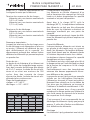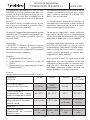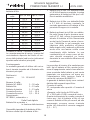
1
Bedienungsanleitung
Operating instructions
Notice d’utilisation
Manuale d’istruzione
POWER PEAK MAXAMP
No. 8121
Bedienungsanleitung
Bestell Nr.
POWER PEAK MAXAMP
8121
Allgemeines
Mit dem MAXAMP können NICD- oder NIMH-Akkus von 1 bis 30 Zellen geladen bzw. entladen werden. Der maximale Ladestrom beträgt 12 A, der maximale Entladestrom 22 A.
Es stehen die Funktionen LADEN, ENTLADEN , mehrfaches ENTLADEN-VOR-LADEN
und mehrfaches LADEN -VOR-ENTLADEN zur Verfügung.
Sicherheitshinweise
- Bei längerem Nichtgebrauch das Ladegerät von der Spannungsquelle trennen und
eventuell angeschlossene Akkus abnehmen.
- Auf freie Kühlöffnungen zur Luftzirkulation achten. – Nicht auf Teppich oder Filz stellen.
- Gerätefüße am Unterboden aufklappen.
- Ladegerät und Akkus nicht auf brennbaren Unterlagen betreiben und nicht unbeaufsichtigt lassen.
- Vor Feuchtigkeit schützen.
- Auf richtige Polung aller Anschlüsse und Ausgänge achten.
- Kurzschlüsse vermeiden.
- Nicht direkter Sonneneinstrahlung aussetzen, Gerät nicht abdecken.
- Keine Akkus laden, die stark erwärmt sind. Akkus auf Umgebungstemperatur abkühlen
lassen.
- Nur schnelladefähige und formierte Akkus verwenden.
- Es dürfen nur Zellen gleicher Kapazität und gleichen Fabrikats im Verbund geladen werden.
- Nicht zwei Akkus zum Laden parallel schalten.
- Nur zum Laden von wiederaufladbaren Akkus geeignet.
- Ladeströme der Höchstbelastung den am Akku befindlichen Kabeln und
Steckverbindungen anpassen.
- Ausgang und Eingang des Geräts nicht miteinander verbinden.
Technische Daten
Betriebsspannung:
Stromaufnahme:
Akkunennspannung:
Ladestrom:
Spannung: 0V ... 18V
max. Strom:
12A
Abschaltautomatik:
Erhaltungsladung:
Entladestrom:
ca. 10 V ... 15 V
leistungsfähige 12V Bleibatterie oder ein leistungsfähiges,
gut stabilisiertes Netzteil (kein Ladegerät für
Autobatterien verwenden!)
max. ca. 40 A!
1,2 V ... 36,0 V (1 ... 30 NICD- / NIMH-Zellen)
0,1 A ... 12 A
18V ... 27V
8A
27V ... 36V
6A
36V ... 45V
5A
über 45V
4A
Delta-Peak-Verfahren und/oder Temperaturabschaltung
keine
0,1 A ... 22 A
Spannung: 0,1V ... 9V 9V ... 13V
max. Strom:
22A
15A
13V ... 18V 18V ... 28V 28V ... 40V 40V ... 50V
11A
7A
5A
4A
3
Bedienungsanleitung
Bestell Nr.
POWER PEAK MAXAMP
8121
Schutzfunktionen:
Ein- und ausgangsseitiger Verpolschutz, ausgangssei tiger Kurzschlußschutz, Übertemperaturschutz,
Unterspannungsschutz
2 Stück, temperaturgeregelt
1 ... 8 NICD- / NIMH-Zellen, Ladestrom ca. 250 mA
ca. 180 x 180 x 70 mm
ca. 950 g
Lüfter:
TX / RX-Ausgang:
Abmessungen:
Gewicht:
Bedienelemente
RX/TX:
Bananenbuchsen
für RX-TX-Akku
MODE-Taste
START/STOP-Taste
CURSOR-Tasten
Eingang:
Krokodilklemmen
zum Anschluß an
Spannungsquelle
Ausgang:
Krokodilklemmen zum Anschluß
des zu ladenden Akkus
UP/DOWN-Tasten
Temperatursensor
Inbetriebnahme
- Die eingangsseitigen Krokodilklemmen an eine 12 V Bleibatterie oder ein entsprechendes Netzteil anschließen; unbedingt auf richtige Polung achten (rot = plus / schwarz =
minus).
- Im Display erscheint „robbe“, das Gerät ist einsatzbereit.
- Den zu ladenden Akku polrichtig mit den ausgangsseitigen Krokoklemmen verbinden
(rot = plus / schwarz = minus). Sollte ein direktes Verbinden des Akkus mit den
Krokoklemmen nicht möglich sein, die Krokoklemmen unbedingt kurzschlußsicher
über ein Ladekabel mit dem Akku verbinden. Falls höherwertige Stecksysteme
anstelle der Krokoklemmen angebracht werden, müssen unbedingt auch die beiden dünnen Meßleitungen angeschlossen werden.
- Im Display erscheint READY (betriebsbereit).
- Wird als Abschaltkriterium die Temperaturabschaltung gewählt, muß der
Temperatursensor thermisch gut leitend mit einem Klebeband am Akku fixiert werden.
4
Bedienungsanleitung
Bestell Nr.
POWER PEAK MAXAMP
8121
Bevor der eigentliche Lade- bzw. Entladevorgang gestartet werden kann, müssen die unten
beschriebenen Parameter eingegeben werden.
Das dazu erforderliche Einstellmenü erscheint nach Anschluß des Akkus.
Im Folgenden wird angenommen, daß das Display im „LONG-DISPLAY“ Modus arbeitet.
Der Modus kann durch die Doppeltastenfunktion (UP- und DN-Taste gleichzeitig kurz
drücken) zwischen LONG und SHORT umgeschaltet werden. Darstellung des „SHORTDISPLAY“ siehe Anhang.
Durch Blättern mit den UP- und DN-Tasten werden die einzustellenden Parameter ausgewählt und mit den CURSOR-Tasten eingestellt. Die linke und rechte Taste dient zur
Auswahl der zu ändernden Ziffern, die obere und untere zur Änderung des ausgewählten
Werts.
-
-
-
-
Einstellung des Ladestroms: Auswahl von SET CH., Einstellen des Ladestroms mit
den CURSOR-Tasten.
Einstellung des Entladestroms: Auswahl von SET DC., Einstellen des Entladestroms
mit den CURSOR-Tasten.
Einstellung der Abschalttemperatur: Auswahl von S.CH.C.TEMP., Einstellen der
Abschalttemperatur mit den CURSOR-Tasten.
Einstellung der Delta-Peak-Empfindlichkeit: Auswahl von S.CH.DELTA, Einstellung
der Delta-Peak-Empfindlichkeit mit den Cursor-Tasten. Einstellbare Werte für NICD
Akkus liegen zwischen 3mV/Zelle und 20mV/Zelle. Zum Laden von NIMH Akkus muß
der Wert 0DV eingestellt werden.
Einstellung der Ladeschlußspannung: Auswahl von S.CH.CUT, generell auf den
Maximalwert von 53 V einstellen.
Einstellung der Entladeschlußspannung: Auswahl von S.DC.CUT, Einstellen der
gewünschten Entladeschlußspannung mit den CURSOR-Tasten. Empfehlung: ca. 0,8 V
pro Zelle.
Die Eingabe der Parameter ist jetzt abgeschlossen.
Mit der MODE-Taste kann zwischen LADEN (CHARGING), ENTLADEN (DISCHARGING), ENTLADEN-VOR-LADEN (DISC-CHAR 01TIME) und LADEN-VOR-ENTLADEN (CHAR-DISC 01TIME) gewählt werden. Die Anzahl der Zyklen (xxTIME) beim
ENTLADEN-VOR-LADEN bzw. beim LADEN-VOR-ENTLADEN kann mit den CURSOR-Tasten zwischen 1 und 99 eingestellt werden.
Gestartet wird die gewählte Betriebsart durch Betätigen der START/STOP-Taste.
Beendet wird der Lade- bzw. Entladevorgang entweder durch die Abschaltautomatik
(Delta-Peak- und/oder Temperaturabschaltung) oder durch Betätigung der
START/STOP-Taste.
Menü / Displays
Die Menüstruktur: Die folgenden Displays können mit den UP- / DN-Tasten ausgewählt
werden. Die oben beschriebenen Parameter werden mit den CURSOR-Tasten eingestellt.
robbe
OUTPUT 11.720 V
Einschaltdisplay
C
Anzeige der momentanen Akkuspannung
5
OUTPUT +0.500 A
C
Bedienungsanleitung
Bestell Nr.
POWER PEAK MAXAMP
8121
Anzeige des momentanen
Entladestroms (-)
Ladestroms
(+)
bzw.
M1 CH. 02120 mAh C
Die letzten 5 eingeladenen Kapazitätswerte, auswählbar mit
CURSOR Tasten
M1 DC. 00000 mAh C
Die letzten 5 entladenen Kapazitätswerte, auswählbar mit
CURSOR Tasten
PEAK 11.835 V
C
AVERAGE 10.719 V C
Anzeige der Maximalspannung
Anzeige der Durchschnittsspannung
CH. TIME 01534S
C
Anzeige der Ladezeit
DC.TIME 00000S
C
Anzeige der Entladezeit
ENERGY 022.60Wh C
Anzeige der eingeladenen / entladenen Energie
TEMPERA. 31.0°C C
Anzeige der Akkutemperatur
SET CH. +05.00 A C
Einstellung des Ladestroms
SET DC. -08.00 A C
Einstellung des Entladestroms
S.CH.C.TEMP 38°C C
Einstellung der Abschalttemperatur
S. CH.DELTA10mVc C
Einstellung der Delta-Peak Empfindlichkeit
S. CH.CUT53.000V C
Einstellung der Ladeschlußspannung
S. DC.CUT05.600V C
Einstellung der Entladeschlußspannung
INPUT 12.33 V
Anzeige der Eingangsspannung
C
6
TX&RX 10.90V
C
Bedienungsanleitung
Bestell Nr.
POWER PEAK MAXAMP
8121
Anzeige der Akkuspannung am TX / RX Ausgang
„C“ bedeutet CHARGING und kann je nach Zustand des Ladegerätes auch durch
R = READY, D = DISCHARGING, D/C = DISC-CHAR (aktiver Zustand blinkt), C/D =
CHAR-DISC (aktiver Zustand blinkt) oder N = NO BATTERY ersetzt sein.
Alle angezeigten Parameter werden beim Anschließen eines Akkus oder beim Umschalten
von Entladen auf Laden bzw. umgekehrt gelöscht, die Kapazitätswerte nach hinten (von M1
nach M2 ...) verschoben.
Die Betriebsarten
Die folgenden Betriebsarten werden mit der MODE-Taste ausgewählt und durch Betätigung
der START / STOP-Taste aktiviert.
CHARGING
Einmaliges LADEN
DISCHARGING
Einmaliges ENTLADEN
CHAR - DISC 01 TIME
Mehrmaliges LADEN-VOR-ENTLADEN, Anzahl mit CURSOR
Tasten einstellbar
DISC - CHAR 03 TIME
Mehrmaliges ENTLADEN-VOR-LADEN, Anzahl mit CURSOR
Tasten einstellbar
Weitere Displays
NO BATTERY
READY
SHORT / REVERSE
Kein Akku angeschlossen
Betriebsbereit
Akku verpolt bzw. Kurzschluß am Ausgang
Ergänzende Hinweise
-
Die Auswahl des Abschaltkriteriums, Delta-Peak-Methode oder Temperaturabschaltung, erfolgt indirekt durch die Einstellungen von Abschalttemperatur und Delta-PeakEmpfindlichkeit. Wird als Abschaltverfahren die Delta-Peak-Methode gewählt, muß die
Abschalttemperatur auf den Maximalwert von 60°C eingestellt werden. Soll nach dem
Temperaturverfahren abgeschaltet werden, muß die Delta-Peak-Empfindlichkeit auf
7
-
Bedienungsanleitung
Bestell Nr.
POWER PEAK MAXAMP
8121
den Maximalwert von 20 mV / Zelle und die Abschalttemperatur auf den gewünschten
Wert eingestellt werden. Natürlich ist es auch denkbar, beide Verfahren quasi parallel
zu verwenden, wobei das Temperaturverfahren gerade beim Laden mit hohen
Laderaten zusätzliche Sicherheit gibt. Man wählt die gewünschte Delta-PeakEmpfindlichkeit und stellt eine Abschalttemperatur von z.B. 45°C ein.
Beim Laden von NIMH-Akkus muß für die Delta-Peak-Empfindlichkeit der Wert 0DV
eingestellt werden.
Der Wert der Ladeschlußspannung hat beim Laden von NICD- und NIMH-Akkus keine
Bedeutung und sollte auf den Maximalwert von 53 V eingestellt werden! Ansonsten
erfolgt die Abschaltung der Ladung, sobald der eingestellte Wert erreicht ist.
Allgemeines über das Laden und Entladen von Akkus
Grundsätzlich sind die Hinweise der Akkuhersteller zu beachten, insbesondere die
Hinweise über maximale Ladeströme.
Um sicherzustellen, daß die Delta-Peak-Automatik optimal arbeiten kann, dürfen nur formierte Akkus schnellgeladen werden, d.h. neue oder längere Zeit nicht benutzte Akkus
müssen in regelmäßigen Zeitabständen entladen und mit kleinen Laderaten, typischerweise C/10 formiert werden.
Ein gelegentliches, vollständiges Entladen wirkt auch dem MEMORY-EFFEKT entgegen.
Während das Laden von Senderakkus, die im Fernsteuersender eingebaut sind, möglich
ist, stehen die Entladefunktionen nur dann zur Verfügung, wenn entweder die
Verpolschutzdiode im Ladezweig des Senders überbrückt wird oder der Akku vom Sender
getrennt und über ein Direktladekabel an das Ladegerät angeschlossen wird.
Der Umbau des Senders sollte durch einen Fachmann, am Besten vom robbe-Service,
durchgeführt werden.
Empfohlene Direktladekabel
No. 8262
F–Serien Sender
No. 8263
Internationale Serie
Anmerkungen
- Beim Laden und Entladen von Akkus mit hohen Lade- bzw. Entladeraten kann - je nach
Akkutyp - evtl. eine Kühlung des Akkus erforderlich sein.
- Der maximale Lade- und Entladestrom hängt von der Zellenzahl des Akkus ab. Siehe
„Technische Daten“.
- Das Beenden des Ladens bzw. Entladens soll nicht durch Abziehen des Akkus erfolgen.
Immer mit der START-STOP-Taste beenden.
Laden von Sender- und Empfängerakkus am RX / TX-Ausgang
Der RX / TX-Ausgang verfügt über keine Abschaltautomatik und dient zum Laden von
Sender- und Empfängerakkus.
Der Ladestrom beträgt ca. 250 mA und kann beim Laden von 8-zelligen Akkus unter
Umständen je nach Spannungslage gegen Ende der Ladung leicht zurückgehen.
Kurzschlüsse und Verpolungen über einen längeren Zeitraum sind zu vermeiden.
Auf keinen Fall dürfen hier Akkus mit mehr als 8 Zellen angeschlossen werden.
8
Bedienungsanleitung
Bestell Nr.
POWER PEAK MAXAMP
8121
Anhang
Short Display
Anstelle des beschriebenen Anzeigeformats „LONG DISPLAY“, besteht auch die
Möglichkeit, den „SHORT DISPLAY“ Modus zu wählen.
Die Umschaltung zwischen beiden Anzeigemodi erfolgt mit der Doppeltastenfunktion der
UP/DN-Tasten (Beide Tasten gleichzeitig kurz betätigen).
Im Short-Display werden zuerst die Einheiten der Werte als Überschrift angezeigt, dann
springt die Anzeige auf die entsprechenden Zahlenwerte. Durch kurzes Drücken der UPTaste können die Einheiten erneut angezeigt werden.
0.V. 0.A. C1mAh C
11.72V 5.00A 2120 C
AVE. PEAK CH.T
Einheiten
Anzeige von Akkuspannung, Lade-/Entladestrom, eingeladener / entladener Kapazität
Zahlenwerte
C
Anzeige von Durchschnittsspannung, Maximalspannung,
Lade-/ Entladezeit
10.7V11.8V1534S C
ENERGY
TEMP. C
Anzeige von eingeladener / entladener Energie und
Akkutemperatur
0.22.60Wh 31.0°C C
SCA SDA SDCV
C
0.5.0A08.0A05.6V C
Einstellung
von
Ladestrom,
Entladeschlußspannung
Entladestrom
und
SCCV SCCT SCDV C
53.00V38°C10mVc C
I.V. TX&RX.V.
C
12.33V 10.90V
C
Einstellung von Ladeschlußspannung, Abschalttemperatur
und Delta-Peak-Empfindlichkeit
Anzeige von Eingangsspannung und Akkuspannung am
TX&RX-Ausgang
Technische Änderungen vorbehalten
9
Operating instructions
Order No.
POWER PEAK MAXAMP
8121
Introduction
The MAXAMP is designed for charging and discharging NiCD and NiMH batteries consisting of 1 to 30 cells. The maximum charge current is 12 A, the maximum discharge current
22 A.
The following functions are available: CHARGE, DISCHARGE, multiple DISCHARGEBEFORE-CHARGE and multiple CHARGE-BEFORE-DISCHARGE.
Safety notes
· If the charger is not to be used for a protracted period, disconnect it from the power
source and remove any battery packs connected to it.
· Be sure to keep the cooling slots unobstructed to provide good air circulation - don’t
stand the charger on a carpet or felt surface.
· Unfold the feet fitted to the underside of the charger.
· Do not set up the charger and batteries on a flammable surface, and never leave the
unit operating unsupervised.
· Protect the unit from damp.
· Take care to maintain correct polarity at all connections and outputs.
· Avoid short-circuits.
· Don’t subject the charger to direct sunshine, and do not cover it.
· Do not charge batteries which are already hot; allow them to cool down to ambient temperature before recharging.
· Use only packs of fast-charge cells which have been properly balanced (equal state of
charge).
· Packs must consist of cells of the same make, type and capacity.
· Do not wire two packs together in parallel for charging.
· The unit is only suitable for use with rechargeable batteries.
· Set charge currents within the maximum rated capacity of the cables and connectors
attached to the battery pack.
· Never connect any charger output to the input.
Specification
Operating voltage:
Current drain:
Nominal battery voltage:
Charge current:
Voltage:
0V … 18V
Max. current:
12A
approx. 10 V ... 15 V DC
high-performance 12 V lead-acid battery or a powerful well
stabilised mains PSU (do not use a car battery charger!)
max. approx. 40 A!
1.2 V ... 36.0 V (1 ... 30 NiCD / NiMH cells)
0.1 A … 12 A
18V … 27V 27V … 36V 36V … 45V
Over 45V
8A
6A
5A
4A
Automatic charge termination: Delta Peak process and/or temperature monitoring
Trickle charge:
none
Discharge current:
0.1 A … 22 A
Voltage:
0.1V … 9V
Max. current:
22A
9V … 13V 13V … 18V 18V … 28V 28V … 40V 40V … 50V
15A
11A
7A
5A
4A
10
Protective functions:
Fans:
TX / RX output:
Dimensions:
Weight:
Operating instructions
Order No.
POWER PEAK MAXAMP
8121
Polarity protection at input and output, short-circuit protec
tion at output, overheating protection,
low voltage protection
2, temperature-controlled
1 … 8 NiCD / NiMH cells, charge current approx. 250 mA
approx. 180 x 180 x 70 mm
approx. 950 g
Charger controls
MODE button
RX/TX
Banana sockets
for RX-TX battery
START/STOP button
CURSOR buttons
Input:
Crocodile clips
for connection
to power source
Output:
Crocodile clips for connection to
battery to be charged
UP/DOWN buttons
Temperature
sensor
Using the charger
· Connect the crocodile clips to a 12 V lead-acid battery or a suitable mains PSU; take
great care over correct polarity (red = positive / black = negative).
· The LCD screen will show „robbe“; the unit is ready to be set up.
· Connect the battery pack to be charged to the output crocodile clips (red = positive /
black = negative). If it is not possible to connect the battery directly to the crocodile clips,
connect the crocodile clips to the battery using a charge lead, taking great care to avoid
short-circuits. If you wish to fit high-quality connectors to the output leads instead
of the crocodile clips, it is essential to connect the two thin measuring wires at
the same time.
· The screen now displays READY (ready for use).
· If you select temperature monitoring as the termination criterion, the temperature sensor must be fixed to the battery with adhesive tape at a point which is an efficient thermal conductor.
11
Operating instructions
Order No.
POWER PEAK MAXAMP
8121
The parameters listed below must now be entered correctly before the actual charge or
discharge process can be started.
The setup menu required for this appears on the screen automatically when you connect
the battery to be charged.
In the following section we assume that the screen is set to „LONG DISPLAY“ mode. The
display mode can be toggled between LONG and SHORT using the double button function
(press the UP and DN buttons briefly together). See appendix for a screen short of the
„SHORT DISPLAY“.
The parameters to be set are selected initially by leafing through the menu using the UP
and DN buttons; the value is set using the CURSOR buttons. The left and right buttons are
used to select the numbers to be changed, the top and bottom buttons to change the selected value.
-
-
-
Setting the charge current: select SET CH, set the charge current using the CURSOR
buttons.
Setting the discharge current: select SET DC, adjust the discharge current using the
CURSOR buttons.
Setting the termination temperature: select S.CH.C.TEMP., adjust the termination
temperature using the CURSOR buttons.
Setting the Delta Peak sensitivity: select S.CH.DELTA, adjust the Delta Peak sensitivity using the cursor buttons. Values for NiCD packs are between 3mV/cell and
20mV/cell. For charging NiMH batteries the 0DV value must be set.
Setting the final charge voltage: select S.CH.CUT, this should normally be set to the
maximum value of 53 V.
Setting the final discharge voltage: select S.DC.CUT, set the desired final discharge
voltage using the CURSOR buttons. Recommendation: approx. 0.8 V per cell.
This concludes the parameter setting process.
By pressing the MODE button you can switch between CHARGING, DISCHARGING,
DISCHARGE-BEFORE-CHARGE (DISC-CHAR 01TIME) and CHARGE-BEFOREDISCHARGE (CHAR-DISC 01TIME). The number of cycles (xxTIME) in the DISCHARGE-BEFORE-CHARGE and CHARGE-BEFORE-DISCHARGE processes can be set to
any number in the range 1 - 99 using the CURSOR buttons.
Press the START/STOP button to start the selected process.
The charge or discharge process is ended by the automatic termination circuit (Delta
Peak and/or temperature monitoring) or by the operator pressing the START/STOP button.
Menus / screen displays
The menu structure: the screen displays shown below can be selected using the UP / DN
buttons. The parameters described above are set using the CURSOR buttons.
robbe
OUTPUT 11.720 V
Power-on display
C
Display momentary battery voltage
12
OUTPUT +0.500 A
C
Operating instructions
Order No.
POWER PEAK MAXAMP
8121
Display momentary charge current (+) or
discharge current (-)
M1 CH. 02120 mAh C
The last 5 charged-in capacity values can be selected using
the CURSOR buttons
M1 DC. 00000 mAh C
The last 5 discharged capacity values can be selected using
the CURSOR buttons
PEAK 11.835 V
C
AVERAGE 10.719 V C
Display maximum voltage
Display average voltage
CH. TIME 01534S
C
Display charge time
DC.TIME 00000S
C
Display discharge time
ENERGY 022.60Wh C
Display charged-in / discharged energy
TEMPERA. 31.0°C C
Display battery temperature
SET CH. +05.00 A C
Set charge current
SET DC. -08.00 A C
S.CH.C.TEMP 38°C C
Set discharge current
Set termination temperature
S. CH.DELTA10mVc C
Set Delta Peak sensitivity
S. CH.CUT53.000V C
Set final charge voltage
S. DC.CUT05.600V C
Set final discharge voltage
INPUT 12.33 V
Display input voltage
C
13
TX&RX 10.90V
Operating instructions
Order No.
POWER PEAK MAXAMP
8121
C
Display battery voltage at TX / RX output
The letter „C“ means CHARGING, and may be replaced by R = READY, D = DISCHARGING, D/C = DISC-CHAR (active state flashes), C/D - CHAR-DISC (active state flashes)
or N = NO BATTERY.
All displayed parameters are erased when you connect a new battery, or switch from
discharge to charge or vice versa, and the capacity values are shifted back by one place
(from M1 to M2, etc.).
Modes of operation
The following modes of operation can be selected using the MODE button, and activated
by pressing the START / STOP button.
CHARGING
Single CHARGE process
DISCHARGING
Single DISCHARGE process
CHAR - DISC 01 TIME
Multiple CHARGE-BEFORE-DISCHARGE process, number
of cycles variable using CURSOR buttons
DISC - CHAR 03 TIME
Multiple DISCHARGE-BEFORE-CHARGE process, number
of cycles variable using CURSOR buttons
Additional screen displays
NO BATTERY
READY
SHORT / REVERSE
No battery connected
Ready for use
Battery connected with reverse polarity / short-circuit at output
Additional information
-
The termination criterion (Delta Peak method or temperature monitoring) is selected
indirectly by the settings you make relating to termination temperature and Delta Peak
sensitivity. If you select the Delta Peak method of charge termination, the termination
temperature must be set to the maximum value of 60ºC. If you wish the unit to terminate the charge process using temperature monitoring, Delta Peak sensitivity must be set
to the maximum value of 20 mV/cell, and the termination temperature set to the desired
14
-
Operating instructions
Order No.
POWER PEAK MAXAMP
8121
value. Of course, it is perfectly feasible to use both processes in parallel, in which case
the temperature monitoring process provides an additional safety margin when charging
at high currents. In this case you should select the desired Delta Peak sensitivity, and
set a termination temperature of, say, 45ºC.
When charging NiMH batteries the value for Delta Peak sensitivity must be set to 0DV.
The value for final charge voltage is not relevant when charging NiCD and NiMH
packs, and should be set to the maximum value of 53 V. If you set a different temperature, the charge process will terminate as soon as the pack reaches the set value.
General information regarding charging and discharging batteries
As a basic rule please be sure to observe the battery manufacturer’s recommendations,
especially the information regarding maximum charge currents.
To ensure that the automatic Delta Peak circuit is able to work as efficiently as possible,
only properly balanced packs should be fast-charged. This means that new batteries, and
packs which have not been used for a long time, should be discharged at regular intervals
and re-balanced by slow-charging at a low rate, typically C/10.
An occasional complete discharge process also helps to avoid and/or eliminate the
MEMORY EFFECT.
It is possible to charge a transmitter battery which is installed in the RC system transmitter,
but the charger’s discharge functions are only available if you either by-pass the protective
diode in the transmitter’s charge circuit, or remove the battery from the transmitter and
connect it to the charger using a direct charge lead.
Conversion work on the transmitter should only be carried out by an expert, ideally by your
nearest robbe Service Centre.
Recommended direct charge leads
No. 8262
F-series transmitter
No. 8263
International series
Notes
- When charging and discharging packs using high charge or discharge currents it may
be necessary to allow the battery to cool down. This varies according to battery type.
- The maximum charge and discharge currents vary according to the number of cells in
the pack; see „Specification“.
- Don’t end the charge or discharge process simply by disconnecting the battery pack;
always stop the process by pressing the START/STOP button.
Charging transmitter and receiver batteries at the RX / TX output
The RX / TX output does not feature any form of automatic termination, and is designed
for charging transmitter and receiver batteries.
The charge current is approximately 250 mA, and this value may fall off slightly towards the
end of the process when charging an 8-cell battery, depending on the pack’s voltage curve.
Short-circuits and long-term reversed polarity must be avoided.
Never connect a pack consisting of more than 8 cells to this output.
15
Operating instructions
Order No.
POWER PEAK MAXAMP
8121
Appendix
Short Display
The „SHORT DISPLAY“ mode can be selected instead of the „LONG DISPLAY“ mode,
which has been described up to this point in these instructions.
Press the UP and DN buttons simultaneously to toggle between these two display modes.
In Short Display mode the screen initially displays the value units, then switches to the corresponding numeric values. The units can be displayed again by pressing the UP button
briefly.
0.V. 0.A. C1mAh C
11.72V 5.00A 2120 C
AVE. PEAK CH.T
C
Units
Display battery voltage, charge / discharge current, chargedin / discharged capacity
Numeric values
Display average voltage, maximum voltage, charge / discharge time
10.7V11.8V1534S C
ENERGY
TEMP. C
Display charged-in / discharged energy and battery temperature
0.22.60Wh 31.0°C C
SCA SDA SDCV
C
Set charge current, discharge current and final discharge voltage
0.5.0A08.0A05.6V C
SCCV SCCT SCDV C
53.00V38°C10mVc C
I.V. TX&RX.V.
C
12.33V 10.90V
C
Set final charge voltage, termination temperature and Delta
Peak sensitivity
Display input voltage and battery voltage at TX/RX output
We reserve the right to alter technical specifications.
16
Notice d’utilisation
Réf.
POWER PEAK MAXAMP
8121
Généralités
Avec le chargeur POWER PEAK MAXAMP est conçu pour la charge rapide et la décharge d’accus de 1 à 30 éléments Cd-Ni ou NiMH. Le courant de charge maximal est de 12 ampères et le
courant de décharge maximal de 22 ampères. L’appareil propose les fonctions suivantes : CHARGE, DÉCHARGE, plusieurs DÉCHARGES-AVANT CHARGES, et plusieurs CHARGES-AVANT
DÉCHARGES.
Consignes de sécurité :
- Lorsqu’il est prévu de ne pas utiliser l’appareil pendant un certain temps, le désolidariser du
secteur et en retirer les accus encore en place.
- Veiller à laisser dégagées les fentes de refroidissement afin de permettre à l’air de circuler.
Ne pas l’installer sur un tapis ou du feutre pour une procédure d charge.
- Rabattre les pieds du fond de l’appareil vers l’extérieur.
- Ne pas disposer les accus et l’appareil sur un support inflammable et ne jamais les laisser
sans surveillance.
- Protéger le chargeur de l’humidité.
- Observer les polarités de tous les branchements et les sorties. Éviter les courts-circuits.
- Ne jamais exposer l’appareil au rayonnement direct du Soleil. Ne pas couvrir l’appareil lorsqu’il est en service.
- Ne pas mettre en charge des accus particulièrement chauds. Avant de les charger, laisser
refroidir les accus à température ambiante.
- N’utiliser que des accus propres à une charge rapide et parfaitement homogènes.
- N’utiliser que des éléments de capacité égale et de même fabrication assemblés en accus.
- Ne pas raccorder deux accus en parallèle pour les charger.
- Le chargeur n’est conçu que pour la charge d’accu effectivement rechargeables.
- Ajuster les courants de charge les plus élevés aux connecteur et cordon solidaires des accus.
- Ne pas raccorder entre elles les entrées et les sorties.
Caractéristiques techniques
Tension de service :
Consommation :
Tension nominale de l’accu :
Courant de charge :
Tension:
Cour. max.
0V ... 18V
12A
approx. 10 à 15 volts CC
accu 12 volts de voiture à capacité appropriées ou bloc
d’alimentation secteur puissant et parfaitement stabilisé (ne
pas utiliser de chargeur pour batterie de voiture).
maximale approx. 40 A
1,2 volt à 36,0 volts (1 à 30 éléments Cd-No / NiMH
0,1 A à 12
18V ... 27V
8A
27V ... 36V
6A
36V ... 45V
5A
plus de 45V
4A
Commutation en fin de charge: Système Delta-Peak ou par commutation thermique
Courant de charge de maintien:néant
Courant de décharge:
0,1 à 22 A
Tension:
Cour. max.:
0,1V ... 9V 9V ... 13V
22A
15A
13V ... 18V 18V ... 28V 28V ... 40V 40V ... 50V
11A
7A
5A
4A
17
Notice d’utilisation
Réf.
POWER PEAK MAXAMP
8121
Fonctions de protection : protection contre les inversions de polarité des entrées et des sor
ties, protection contre les courts-circuits côté sortie., protection con
tre les températures excessives et contre les tensions insuffisantes.
Ventilateur :
2 unités avec thermorégulation
Sortie TX/RX :
1 à 8 éléments Cd-Ni / NiMH, courant de charge de 250 mA environ
Encombrement :
approx. 180 x 180 x 70 mm
Poids :
approx. 950 g
Éléments de commande
Touche de MODE
RX/TX :
Touche MARCHE/ARRET
connecteurs douilles
banane pour accus
Rx/Tx
Touches CURSEUR
Entrée: pinces
crocodile pour
connexion à
la source d’alimentation
Sortie :
pinces crocodile pour connexion
à l’accu à charger
Touches UP/DOWN
Thermocapteur
Mise en service
- Raccorder les pinces crocodile à une batterie au plomb de 12 volts ou à bloc d’alimentation secteur approprié ; veiller absolument à respecter les polarités (rouge = plus / noir
= moins) - cf. également le paragraphe « Bloc d’alimentation secteur ».
- Sur l’écran apparaît la mention « robbe », l’appareil est en ordre de marche.
- Raccorder l’accu à charger en respectant les polarités avec les pinces crocodile côté sortie (rouge = plus / noir = moins). S’il s’avérait impossible de raccorder les pinces crocodile, les protéger contre les courts circuits.Si vous utilisez un système de connexion de
qualité supérieure aux pinces crocodile, il faut également raccorder absolument les deux
brins métalliques des conduites de mesure.
- Sur l’écran apparaît la mention READY (en ordre de marche).
- Lorsque la température est choisie comme critère de commutation en fin de charge, il
faut fixer le capteur de température avec un morceau de ruban adhésif à l’accu afin que
la chaleur soit parfaitement conduite.
18
Notice d’utilisation
Réf.
POWER PEAK MAXAMP
8121
Avant de lancer une procédure de charge ou de décharge proprement dite, il faut saisir les
paramètres présentés ci-dessous.
Le menu de mise au point indispensable apparaît après connexion de l’accu d’alimentation.
Dans les paragraphes qui suivent, ont part du principe que l’écran travaille en mode «
LONG-DISPLAY ». Il est possible de choisir entre les menu LONG et SHORT pour la représentation sur l’écran en actionnant brièvement simultanément les touches UP et DN. Pour la
représentation courte « SHORT » sur l’écran, cf. en annexe.
L’écran permet avec les touches UP et DN de sélectionner à l’aide des touches du CURSEUR les paramètres à mettre au point. La touche gauche et la touche droite permettent de
sélectionner les chiffres à modifier et les flèches du haut et du bas à changer les valeurs
sélectionnées.
-
-
-
-
Réglage du courant de charge : sélectionner SET CH. Régler le courant de charge
avec les touches du CURSEUR.
Réglage du courant de décharge : sélectionner SET DC. Régler le courant de décharge avec les touches du CURSEUR.
Réglage de la température de coupure : sélectionner S.CH.C.TEMP., régler la
température de coupure à l’aide des touches du CURSEUR.
Réglage de la sensibilité Delta-Peak : sélectionner S.CH.DELTA., régler la sensibilité
du système Delta-Peak à l’aide des touches du CURSEUR. Les valeurs réglables pour
les accus Cd-Ni varient entre 3mV/élément et 20mV/élément. Pour charger les accus
NiMH, il faut régler la valeur 0DV.
Réglage de la tension en fin de charge : sélectionner S.CH.CUT, généralement c’est
la valeur maximale de 53 V qui est établie.
Réglage de la tension en fin de décharge : sélectionner S.DC.CUT, sélectionner la
tension de fin de décharge souhaitée à l’aide des touches du CURSEUR. Nous recommandons une valeur de 0,8 volt environ par élément.
La saisie des paramètres est ainsi achevée.
À l’aide de la touche MODE vous avez maintenant la possibilité de choisir entre CHARGE (CHARGING), DÉCHARGE (DISCHARGING), DÉCHARGE-AVANT CHARGE
(DISC-CHAR 01TIME) et CHARGE-AVANT DÉCHARGE (CHAR-DISC 01TIME). Le
nombre de cycles (xxTIME) pour DÉCHARGE-AVANT CHARGE et CHARGE-AVANT
DÉCHARGE peut être sélectionné à l’aide des touches de cusrseur entre 1 et 99.
Le mode choisi est lancé en actionnant la touche MARCHE/ARRET (START/STOP).
La procédure de charge ou de décharge s’arrête soit en mode automatique (Delta-Peak
ou/et coupure en fonction de la température) ou en actionnant la touche
MARCHE/ARRET (START/STOP).
Écrans à menu
La structure du menu : les écrans suivants peuvent être sélectionnés à l’aide des touches
UP / DN. Les paramètres décrits ci-dessous sont mis au point à l’aide des touches de CURSEUR.
robbe
OUTPUT 11.720 V
Écran de mise en marche
C
Affichage de la tension momentanée de l’accu
19
Notice d’utilisation
Réf.
POWER PEAK MAXAMP
8121
C
Affichage du courant de charge (+) ou de décharge (-)
momentané
M1 CH. 02120 mAh C
Les 5 dernières valeurs de capacité chargées, sélectionnables à l’aide des touches du CURSEUR.
M1 DC. 00000 mAh C
Les 5 dernières valeurs de capacité déchargées, sélectionnables à l’aide des touches du CURSEUR.
OUTPUT +0.500 A
C
Affichage de la tension maximale
AVERAGE 10.719 V C
Affichage de la tension moyenne
PEAK 11.835 V
CH. TIME 01534S
C
Affichage de la durée de la charge
DC.TIME 00000S
C
Affichage de la durée de la décharge
ENERGY 022.60Wh C
TEMPERA. 31.0°C C
Affichage de l’énergie chargée / déchargée
Affichage de la température de l’accu
SET CH. +05.00 A C
Réglage du courant de charge
SET DC. -08.00 A C
Réglage du courant de décharge
S.CH.C.TEMP 38°C C
Réglage de la température de coupure
S. CH.DELTA10mVc C
Réglage de la sensibilité Delta-Peak
S. CH.CUT53.000V C
Réglage de la tension en fin de charge
S. DC.CUT05.600V C
Réglage de la tension en fin de décharge
INPUT 12.33 V
Affichage de la tension d’alimentation du chargeur
C
20
TX&RX 10.90V
C
Notice d’utilisation
Réf.
POWER PEAK MAXAMP
8121
Affichage de la tension de l’accu à la sortie TX/RX.
« C » signifie CHARGING et peut, en fonction de l’état du chargeur, être remplacé par R =
READY, D = DISCHARGING, D/C = DISC-CHAR (l’état activé clignote), C/D = CHARDISC (l’état activé clignote) ou N = NO BATTERY.
Tous les paramètres affichés sont effacés lorsqu’on raccorde un accu ou lorsqu’on commute de décharge sur charge et inversement, les valeurs de capacité sont décalées vers
l’arrière (de M1 vers M2 ....).
Les modes
Les modes suivants peuvent être sélectionnés à l’aide de la touche MODE et activés en
actionnant la touche START/STOP.
CHARGING
CHARGE unique
DISCHARGING
DÉCHARGE unique
CHAR - DISC 01 TIME
Plusieurs CHARGES-AVANT DÉCHARGES, sélectionner le
nombre de cycles à l’aide des touches du CURSEUR.
DISC - CHAR 03 TIME
Plusieurs DÉCHARGES-AVANT CHARGES, sélectionner le
nombre de cycles à l’aide des touches du CURSEUR.
Autres écrans
NO BATTERY
Pas d’accu raccordé
READY
En ordre de marche
SHORT / REVERSE
Polarités inversées de l’accu ou court-circuit à la sortie
Informations complémentaires :
- La sélection du critère de coupure en fin de charge, c’est-à-dire la méthode DeltaPeak ou la coupure en fonction de la température, intervient indirectement par la mise
au point des valeurs de la température de coupure et de la sensibilité Delta-Peak. Si
l’on opte pour la méthode Delta-Peak de coupure automatique en fin de charge, il faut
disposer la température de coupure sur la valeur maximale de 60° C. Si l’on opte pour
la méthode de coupure automatique en fin de charge en fonction de la température, il
faut régler la sensibilité Delta-Peak sur la valeur maximale de 20 mV par élément et la
21
-
Notice d’utilisation
Réf.
POWER PEAK MAXAMP
8121
valeur de commutation de la température au choix. Il est bien sûr également possible
d’utiliser les deux méthodes à la fois, pratiquement en parallèle, la procédure de
température offrant toutefois plus de sécurité pour les charges à taux de charge élevés.
On sélectionne alors la sensibilité Delta-Peak souhaitée et on règle la température de
coupure sur, par exemple, 45° C.
Pour charger les accus NiMH il faut régler la sensibilité Delta-Peak sur la valeur 0DV.
La valeur de tension de fin de charge pour la charge des accus Cd-Ni et des accus
NiMH n’a pas de signification et doit être réglée sur la valeur maximale de 53 V. Sinon
la charge est interrompue dès que la valeur réglée est atteinte.
Généralités concernant la charge et la décharge d’accus
Il faut en règle générale observer formellement les recommandations du fabricant de l’accu, particulièrement en ce qui concerne les courants de charge maximaux.
Pour s’assurer que le dispositif de commutation automatique Delta-Peak en fin de charge
fonctionne correctement, il ne faut mettre en charge rapide des accus dont les éléments
sont parfaitement homogènes, c’est-à-dire que les accus neufs ou qui n’ont pas été utilisés
depuis un certain temps doivent être déchargés à intervalles réguliers ou être formés avec
de petits chargeurs assurant une charge de type C/10.
Une décharge complète de temps en temps a aussi un effet contre l’effet de mémoire des
accus. Pendant la charge d’accus d’émetteur installés dans l’émetteur, ce qui est possible,
les fonctions de décharge ne sont cependant disponibles que lorsque la diode de protection contre les inversions de polarité est shuntée au niveau du branchement de charge de
l’émetteur ou lorsque l’accu est désolidarisé de l’émetteur et raccordé directement au chargeur par un cordon de charge directe.
La transformation nécessaire au niveau de l’émetteur doit être confiée à un spécialiste et
de préférence au service après-vente robbe.
Cordons de charge directe recommandés
réf. 8262 émetteurs de la série F
réf. 8263 série internationale
Remarques
- Pour la charge ou la décharge d’accus à hauts taux de charge ou de décharge il peut
s’avérer indispensable - selon le type d’accu - d’assurer un refroidissement des accus.
- Le courant de charge ou de décharge maximal dépend du nombre des éléments de l’accu, cf. « Caractéristiques techniques ».
- La fin de la charge ou de la décharge ne doit jamais intervenir en retirant l’accu du chargeur. La stopper à l’aide de la touche START-STOP.
Charge d’accus d’émetteur et de récepteur à la sortie RX/TX
La sortie RX/TX ne dispose pas d’automatisme de coupure en fin de charge, elle est
conçue pour la charge d’accus d’émission et de réception.
Le courant de charge est de 250 mA environ, il est susceptible de diminuer légèrement en
fin de charge avec des accus de 8 éléments dans certaines circonstances et en fonction du
niveau de charge.
Les courts-circuits et les inversions de polarité sont à éviter à long terme. En aucun cas ne
raccorder des accus de plus de 8 éléments à cette sortie.
22
Notice d’utilisation
Réf.
POWER PEAK MAXAMP
8121
Annexe
Écran abrégé
En remplacement du format d’affichage „LONG DISPLAY“ décrit antérieurement, il est possible de choisir un mode d’affichage abrégé („SHORT DISPLAY“).
La commutation entre les deux types d’affichages intervient à l’aide des touches UP/DN
actionnées brièvement et simultanément.
L’écran abrégé présente d’abord la dénomination des valeurs mémorisées en titre puis il
saute sur les valeurs elles-mêmes. Une action brève sur la touche UP permet de revenir
aux unités.
0.V. 0.A. C1mAh C
11.72V 5.00A 2120 C
AVE. PEAK CH.T
C
Unités
Affichage de la tension de l’accu, du courant de
charge/décharge, de la capacité chargée/déchargée.
Valeurs chiffrées
Affichage de la tension moyenne, de la tension maximale et
de la durée de la charge/décharge.
10.7V11.8V1534S C
ENERGY
TEMP. C
Affichage de l’énergie chargée/déchargée et de la température de l’accu.
0.22.60Wh 31.0°C C
SCA SDA SDCV
C
Réglage du courant de charge, du courant de décharge et de
la tension en fin de décharge.
0.5.0A08.0A05.6V C
SCCV SCCT SCDV C
53.00V38°C10mVc C
I.V. TX&RX.V.
C
12.33V 10.90V
C
Réglage de la tension en fin de charge, de la température de
commutation en fin de charge et de la sensibilité Delta-Peak.
Affichage de la tension d’admission et de la tension de l’accu
à la sortie Tx/Rx.
Sous réserve de modification technique.
23
Manuale d’istruzione
Codice
POWER PEAK MAXAMP
8121
Introduzione
Il MAXAMP è un caricabatteria automatico progettato per la carica , scarica e manutenzione di pacchi batterie sia NICD che NIMH da 1 a 30 celle con fine carica gestito dal sistema a lettura di picco “Delta Peak“.
La corrente massima di carica è di 12 A, mentre la corrente massima si scarica è di 22 A.
Norme di Sicurezza
- Se il caricabatteria rimane inutilizzato per un periodo prolungato è consigliabile scollegare sia l’alimentazione di ingresso e sia ogni batteria in uscita.
- Assicurarsi di mantenere le feritoie di aerazione pulite e senza impedimento alcuno al
fine di assicurare una corretta circolazione d’aria per il raffreddamento.
- Aprire i supporti al involucro posteriore.
- Non utilizzare il caricabatteria appoggiato ad una superficie infiammabile e non lasciare
mai l’apparecchio incustodito durante il processo di carica-scarica.
- Proteggere l’apparecchio da eventuali urti
- Prestare attenzione a non invertire le polarità di alimentazione in ingresso ed uscita.
- Evitare corti circuiti
- Non lasciare il caricabatteria al sole ed evitare di coprirlo durante l’uso
- Non caricare batterie già calde: lasciarle raffreddare fino alla temperatura ambiente
prima della ricarica.
- Utilizzare solo pacchi a carica rapida precedentemente “bilanciati” con una carica-scarica lenta.
- I pacchi devono essere formati da celle uguali tra loro: non mescolare celle di capacità
e marche diverse.
- Non collegare due pacchi in parallelo per la ricarica
- Il POWER PEAK MAXAMP è progettato solamente per essere impiegato per la carica
di batterie ricaricabili. Selezionare correnti di carica comprese nei valori massimi suggeriti dal costruttore e proporzionati al cavo e/o connettore della batteria utilizzata.
- Mai collegare un altro caricabatteria all’uscita.
Specifiche
Tensione di alimentazione :
Corrente assorbita:
Tensione nominale batteria uscita
Corrente di carica :
Voltaggio:
0V ... 18V
Corr. mass.:
12A
Interruzione carica:
Carica di mantenimento:
Corrente di scarica :
10 V ... 15 V DC circa
Batteria al piombo o alimentatore stabilizzato e ben fil
trato alimentato a rete. (NON UTILIZZARE MAI UN
CARICABATTERIE 12V D’AUTO)
40 A circa massimo
1,2V….36.0V (1….30 elementi per NICD/NIMH)
0,1 A ... 12 A
18V ... 27V
8A
27V ... 36V
6A
36V ... 45V
5A
45V......
4A
a lettura di picco “ Delta Peak “ e/o a temperatura
niente carica di mantenimento
0,5 A ... 22,0 A programmabile
Voltaggio:
0,1V ... 9V 9V ... 13V
Corr. mass.:
22A
15A
13V ... 18V 18V ... 28V 28V ... 40V 40V ... 50V
11A
7A
5A
4A
24
Protezioni:
Ventole:
Uscita TX/RX
Dimensioni:
Peso
Manuale d’istruzione
Codice
POWER PEAK MAXAMP
8121
Inversione di polarità ingresso uscita, corto circuito in uscita, prote
zione contro il surriscaldamento, protezione in caso di alimentazione
d’ingresso bassa, protezione alta tensione
2 controllate da termostato
1…8 Celle sia NiCd che NiMh con corrente di carica di circa 250mA
180 x 180 x 70 mm
950 g.
Funzioni
Tasto scelta modalità d’uso Tasto di START/STOP
RX/TX
Boccole uscita per
Tasti CURSORE
batterie RX-TX.
Entrata:
Coccodrilli di
ingresso per
entrata 12 Vcc
USCITA:
coccodrilli per il collegamento della
batteria da caricare
Tasti SALITA/DISCESA
Sensore di
temperatura
Uso del caricabatteria
- Connettere I coccodrilli d’ingresso alla batteria 12 V oppure ad un appropriato alimentatore stabilizzato prestando particolare attenzione alle polarità.
- Lo schermo a cristalli liquidi LCD mostrerà la scritta “robbe“ indicando che il caricabatteria è pronto per l’uso.
- Collegare il pacco batterie da caricare ai coccodrilli d’uscita avendo cura di rispettare
le polarità. (Rosso = positivo. Nero = negativo). Nel caso non sia possibile collegare i
coccodrilli direttamente alla batteria da caricare collegateli ad un cavo di ricarica evitando accuratamente inversioni di polarità e cortocircuiti. Se si desidera sostituire i coccodrilli in uscita con connettori di alta qualità è essenziale collegare i due
cavi contemporaneamente.
- Sullo schermo apparirà ora la scritta READY (pronto all’uso)
- Se viene scelto il monitoraggio della temperatura per la gestione del fine carica il sensore di temperatura deve essere fissato saldamente alla batteria da caricare con del
nastro adesivo in un punto dove il calore si propaga facilmente.
25
Manuale d’istruzione
Codice
POWER PEAK MAXAMP
8121
I parametri descritti di seguito devono essere ora inseriti correttamente prima di iniziare il
processo di carica o scarica.
Nella sezione seguente si suppone che lo schermo LCD visualizzi la schermata “LONG
DISPLAY” (letteralmente “LUNGA SCHERMATA” che visualizza informazioni più dettagliate).
La scelta tra “LONG DISPLAY” o “SHORT DISPLAY” può essere effettuata premendo contemporaneamente per alcuni istanti i tasti “UP” e “DOWN”. Consultare l’appendice per una
breve descrizione della funzione SHORT DISPLAY.
I parametri da programmare sono selezionabili scorrendo il menù utilizzando i tasti UP e
DOWN ; il valore desiderato può essere impostato premendo i tasti CURSORE (CURSOR).
Premere i tasti destro (right) o sinistro (left) per selezionare il valore che si desidera modificare, i tasti sopra (UP e sotto (DOWN) cambieranno il valore selezionato.
-
-
-
-
Come fissare la corrente di carica: selezionare la videata SET CH ed impostare il
valore di corrente desiderato utilizzando i tasti CURSORE (CURSOR).
Come fissare la corrente di scarica: selezionare la videata SET DC ed impostare il
valore di corrente desiderato utilizzando i tasti CURSORE (CURSOR).
Come fissare la temperatura di fine carica: selezionare la videata S.CH.C.TEMP., ed
impostare la temperatura desiderata utilizzando i tasti CURSORE (CURSOR).
Come fissare la sensibilità del Delta Peak: selezionare la videata S.CH. DELTA, ed
impostare il valore desiderato utilizzando i tasti CURSORE (CURSOR). Scegliere per
pacchi al NiCd un valore compreso tra 3 mV/cella e 20 mV/cella. Per la ricarica di batterie NiMh è necessario invece impostare il valore ODV.
Come fissare il valore di tensione di fine carica: selezionare la videata S.CH.CUT,
normalmente viene impostato il valore massimo di 53V.
Come fissare il valore di tensione di fine scarica: selezionare la videata S.DC.CUT,
ed impostare il valore desiderato utilizzando i tasti CURSORE (CURSOR).
Raccomandiamo un valore di 0,8 V per elemento.
Sin qui l’impostazione dei vari parametri di carica/scarica.
Premendo il tasto MODE è possibile scegliere la modalità di CHARGING (CARICA),
DISCHARGING (SCARICA), DISC-CHAR 01 TIME (SCARICA-CARICA 1 VOLTA),
CHAR-DISC 01 TIME (CARICA-SCARICA 1 VOLTA). Il numero di cicli di carica nell’opzione SCARICA-CARICA e CARICA-SCARICA può essere scelto tra un numero compreso tra 1 e 99 utilizzando sempre i tasti CURSORE.
Premere il tasto START/STOP per iniziare il processo di carica e/o scarica selezionato.
Il ciclo di carica o scarica può concludersi a lettura di picco, lettura di temperatura oppure premendo nuovamente il tasto START/STOP.
La carica o scarica può essere interrotta automaticamente oppure manualmente dall’utente premendo il tasto START/STOP.
Videate/Displays
La struttura delle videate: Le seguenti videate possono essere scelte premendo i tasti UPDN. I parametri sopra descritti vengono impostate con i tasti CURSOR(E).
robbe
Caricabatteria acceso
Tensione batteria in carica
OUTPUT 11.720 V
C
26
OUTPUT +0.500 A
C
Manuale d’istruzione
Codice
POWER PEAK MAXAMP
8121
Corrente di carica (+) o scarica (-) batteria
M1 CH. 02120 mAh C
Gli ultimi 5 valori di capacità di carica possono essere visualizzati utilizzando i tasti CURSOR(E)
M1 DC. 00000 mAh C
Gli ultimi 5 valori di capacità di scarica possono essere visualizzati utilizzando i tasti CURSOR(E)
PEAK 11.835 V
C
AVERAGE 10.719 V C
Visualizzazione picco massimo di tensione
Visualizzazione voltaggio medio batteria in uscita
CH. TIME 01534S
C
Visualizzazione tempo di carica
DC.TIME 00000S
C
Visualizzazione tempo di scarica
ENERGY 022.60Wh C
Visualizzazione dell’energia di carica o scarica
TEMPERA. 31.0°C C
Visualizzazione della temperatura di batteria
SET CH. +05.00 A C
Scelta del valore della corrente di carica.
SET DC. -08.00 A C
S.CH.C.TEMP 38°C C
Scelta del valore della corrente di scarica.
Scelta del valore della temperatura di interruzione carica.
S. CH.DELTA10mVc C
Scelta del valore della sensibilità del DELTA PEAK.
S. CH.CUT53.000V C
Scelta del valore del valore finale di tensione di fine carica.
S. DC.CUT05.600V C
Scelta del valore del valore finale di tensione di fine scarica.
INPUT 12.33 V
Visualizzazione della tensione in ingresso.
C
27
TX&RX 10.90V
C
Manuale d’istruzione
Codice
POWER PEAK MAXAMP
8121
Visualizzazione della tensione della batteria collegata sull’uscita TX RX
La lettera C indica la carica in corso. Al suo posto possono anche apparire le seguenti lettere: R=READY (PRONTO), D=DISCHARGE(SCARICA IN CORSO), D/C = DISC-CHAR
(SCARICA-CARICA), C/D = CHAR-DISC (CARICA-SCARICA) dove lo stato di carica o
scarica è evidenziato dalla lettera relativa lampeggiante ed infine N che indica l’assenza
di batteria da caricare collegata all’uscita. (NO BATTERY)
Tutti i parametri visualizzati vengono cancellati collegando una nuova batteria oppure commutando da scarica in carica e viceversa. I valori di capacità vengono slittati di un posto (da
M1 a M2, ecc).
Modalità d’uso
Possono essere selezionate le seguenti modalità d’uso premendo il tasto MODE e successivamente attivate premendo il tasto START/STOP.
CHARGING
Processo di carica singolo
DISCHARGING
Processo di scarica singolo
CHAR - DISC 01 TIME
Ciclo di carica-scarica: il numero dei cicli può essere variato
dai tasti CURSOR(E)
DISC - CHAR 03 TIME
Ciclo di scarica-carica: il numero dei cicli può essere variato
dai tasti CURSOR(E)
Informazioni aggiuntive visualizzate sullo schermo LCD
NO BATTERY
READY
SHORT / REVERSE
Nessuna batteria collegata in uscita.
Pronto all’uso
Batteria in uscita collegata con polarità invertita oppure in
corto circuito
Informazioni supplementari
- Il criterio di fine carica (sistema Delta Peak o lettura della temperatura) è indirettamente selezionata dalla scelta effettuata: delta peak oppure a temperatura. Se viene
selezionato il sistema a lettura di picco “Delta Peak” il limite di temperatura deve essere portato al valore massimo di 60° C mentre se si sceglie d’interrompere la carica
“monitorando” la temperatura è necessario fissare il valore di sensibilità a 20mV/cella e
il valore massimo di temperatura al quale si vuole far interrompere la carica. I due sistemi di gestione del fine carica possono essere anche utilizzati in “parallelo” . In questo
modo il monitoraggio della temperatura fornirà una sicurezza ulteriore specialmente
nella carica di batterie con correnti molto elevate. Si consiglia di scegliere la sensibilità
28
-
Manuale d’istruzione
Codice
POWER PEAK MAXAMP
8121
desiderata del Delta Peak e di fissare una temperatura massima di 45° C
Durante la carica di batterie NiMh il valore del Delta Peak deve essere impostato a 0DV
Il valore della tensione finale è un dato irrilevante sia per le NiCd che per NiMh ed è
opportuno impostare il valore massimo consentito dal caricabatteria: 53 V. Nel caso si
selezionasse una temperatura differente la carica sarà interrotta al raggiungimento della
temperatura impostata.
Informazioni generali sulla carica e scarica delle batterie
Come regola generale assicuratevi di osservare sempre le raccomandazioni del costruttore delle batterie in vostro possesso e che vi accingete a ricaricare con particolare attenzione alla corrente massima di carica e scarica.
Per essere sicuri che il sistema a lettura di picco funzioni il più correttamente possibile si
raccomanda di caricare con carica rapida solo pacchi bilanciati. Questo significa che ogni
nuovo pacco o pacchi rimasti inattivi per un lungo periodo dovrebbero essere scaricati ad
intervalli regolari e ricaricati con carica lenta con corrente pari a 1/10 della capacità nominale.
Una scarica completa da ripetersi di tanto in tanto aiuta anche a prevenire ed eliminare il
tipico EFFETTO MEMORIA delle batterie NICD.
Alcuni vecchi pacchi o batterie di bassa qualità possono impedire il corretto funzionamento del caricabatteria. In questi casi si raccomanda di tenere il caricabatteria costantemente sotto controllo durante la fase di carica e scarica.
È possibile caricare pacchi TX che normalmente sono installati all’interno del trasmettitore.
In questo caso la funzione di scarica non può essere utilizzata senza prima rimuovere il
pacco dal trasmettitore oppure senza aver ponticellato il diodo di protezione all’interno del
radiocomando. Si raccomanda di far eseguire quest’ultima operazione dal centro assistenza ROBBE più vicino.
Cavo di ricarica raccomandato per collegamento diretto
No. 8262
per radio serie F
No. 8263
tutte le radio FUTABA
Alcune Note
- Nella carica/scarica di pacchi batterie con elevate correnti è necessario, prima del loro
utilizzo, lasciarle raffreddare
- La corrente di carica e scarica massima varia in ragione del numero di celle collegate:
vedere le specifiche per ulteriori dettagli.
- Non interrompere la carica o scarica semplicemente scollegando la batteria collegata:
interrompete il processo in corso premendo il tasto MODE (START-STOP).
Ricarica delle batterie trasmittente e ricevente collegate all’uscita RX/TX.
L’uscita RX/TX non è gestita da alcun tipo di automatismo ed è progettata per la ricarica del pacco TX o RX.
La corrente di carica è di circa 250 MA fissa. Il suo valore può essere leggermente inferiore in presenza di un pacco da 8 celle verso la fine della carica. É consigliabile evitare corto
circuiti e periodi lunghi con batteria collegata a polarità invertita. Non collegare mai un
pacco superiore alle 8 celle su quest’uscita.
29
Manuale d’istruzione
Codice
POWER PEAK MAXAMP
8121
Appendice.
SHORT DISPLAY
Al posto della modalità LONG DISPLAY è possibile selezionare l’opzione SHORT DISPLAY.
Premer i tasti UP e DN simultaneamente per passare da una modalità all’altra. Nell’opzione
SHORT DISPLAY lo schermo visualizza inizialmente i valori unitari. I corrispondenti valori
numerici appariranno subito dopo. E’ possibile passare ai valori unitari nuovamente premendo brevemente il tasto UP.
0.V. 0.A. C1mAh C
11.72V 5.00A 2120 C
AVE. PEAK CH.T
Dati Visualizzati
Tensione di batteria, corrente di carica/scarica, quantità di
carica e scarica
Valori numerici
C
Visualizzazione voltaggio medio, picco massimo, tempo di
carica e scarica
10.7V11.8V1534S C
ENERGY
TEMP. C
Visualizzazione energia di carica/scarica e temperatura di
batteria
0.22.60Wh 31.0°C C
SCA SDA SDCV
C
0.5.0A08.0A05.6V C
Programmazione della corrente di carica, corrente di scarica
e voltaggio minimo di scarica.
SCCV SCCT SCDV C
53.00V38°C10mVc C
I.V. TX&RX.V.
C
12.33V 10.90V
C
Programmazione del voltaggio finale di carica, temperatura
massima di fine carica e sensibilità del “Delta peak”
Visualizzazione tensione di ingresso e della batteria collegata
all’uscita TX&RX
Ci riserviamo il diritto di apportare ogni eventuale variazione tecnica senza che questo
costituisca obbligo alcuno nei confronti dell’acquirente. Ogni diritto riservato
30
robbe Modellsport GmbH & Co. KG
Metzloserstr. 36
Telefon: 06644 / 87-0
36355 Grebenhain
FAC
Ergänzungsanleitung
Supplementary Instructions
Notice Complémentaire
Istruzioni Aggiuntive
Instrucciones Adicionales
POWER PEAK MAXAMP LI
No. 8121
Ergänzungsanleitung
POWER PEAK MAXAMP LI
No. 8121
Die Software des Ladegerätes POWER
PEAK MAXAMP LI wurde um die Möglichkeit des Ladens- und Entladens von bis zu
12 Lithium- und Lithium-Ionen-Polymer
Zellen erweitert, und trägt nun die ZusatzBezeichnung Li.
Ebenfalls können nun Bleiakkus mit bis zu
42 Volt Nennspannung ge- und entladen
werden.
Durch unterschiedliche Einstellung der
Abschaltkriterien können die 4 verschiedenen Akkutypen NC, NiMH, Lithium und
Blei geladen und entladen werden.
Bitte lesen Sie diese Anleitung unbedingt
vor dem Laden, um Schäden zu vermeiden.
Werden die in der Tabelle empfohlenen
Richtwerte eingestellt, so erfolgt die Abschaltung meist gemäß dem HauptAbschaltkriterium (dunkles Feld in der
Tabelle)
Die automatische Abschaltung erfolgt, je
nach dem welche Einstellwerte vorgegeben werden und welcher Wert zuerst
erreicht wird.
Allgemeines:
Der MAXAMP LI Lader besitzt verschiedene, frei konfigurier- und einstellbare Abschaltkriterien:
Achten Sie insbesondere bei Lithium und Bleiakkus auf eine exakte Einstellung
der Abschaltspannung. Falsche Einstellung führt zu Akkudefekten.
Laden:
1. Delta Peak Abschaltung
2. Ladeschluss-Spannungs-Abschaltung
3. Temperaturabschaltung
Lithium-Akkus sind nach Ende der
Ladung möglichst bald vom Lader zu
trennen, ein technisch bedingter Reststrom (10 mA) könnte sonst Akkus kleiner
Kapazität langfristig überladen.
Entladen:
Entladeschluss-Spannungs-Abschaltung.
Parameter
LADEN
Nicad
NiMH
Blei
Lithium
(3,7V Zelle)
S.CH.DELTA XXmV)
Delta Peak Abschaltung
0...10 mV
0 DVEinstellung
20 mV
20 mV
S.CH.C.TEMP XX°C
Temperaturabschaltung
40...45° C
40...45° C
40° C
40...45° C
ca. 1,8 V /
Zelle
ca. 1,8 V /
Zelle
2,35 Volt x
Zellenzahl
4,2 Volt x
Zellenzahl
ca. 0,85 V /
Zelle
ca. 0,9...1 V /
Zelle
1,75 Volt x
Zellenzahl
3 Volt x
Zellenzahl
S.CH.CUT XX,xxxV
Ladeschluss-SpannungsAbschaltung
ENTLADEN
S.DC.CUT XX,xxxV
Entladeschluss-SpannungsAbschaltung
2
Ergänzungsanleitung
POWER PEAK MAXAMP LI
Allgemeines zu Lithium Akkus
Es gibt verschiedene Lithium Akkutypen:
Ladeschluss-Spannungs-Tabelle
für Lithium Akkus:
Zellenzahl
1
2
3
4
5
6
7
8
9
10
11
12
3,6 Volt Typ
4,1 V
8,2 V
12,3 V
16,4 V
20,5 V
24,6 V
28,7 V
32,8 V
36,9 V
41,0 V
45,1 V
49,2 V
3,7 Volt Typ
4,2 V
8,4 V
12,6 V
16,8 V
21,0 V
25,2 V
29,4 V
33,6 V
37,8 V
42,0 V
46,2 V
50,4 V
1. Lithium-Ionen Akkus mit flüssigem
Elektrolyt und 3,6 Volt Nennspannung,
die erste Generation der Lithium
Akkus, im Modellbau kaum verbreitet.
2. Lithium-Ionen Akkus mit flüssigem
Elektrolyt und 3,7 Volt Nennspannung,
die zweite Generation von Lithium
Akkus, mit Metallbecher.
3. Lithium-Ionen-Polymer Akkus mit gelförmigem Elektrolyt und 3,7 Volt Nennspannung, die derzeit aktuelle Generation von Lithium Akkus, auch Lipoly
genannt. Durch den gelartigen Elektrolyt entsteht beim Laden bzw. Entladen
weniger Druck in der Zelle, weshalb
eine Folienummantelung ausreicht.
Wegen des geringen Gewichtes und
der hohen Energiedichte hat sie sich
schnell im Modellbau verbreitet.
Ladestrom / Entladestrom:
Der maximale Ladestrom / Entladestrom
des Laders ist abhängig von der Spannungslage des Akkus (siehe auch Angaben
in der Hauptanleitung).
Das Ladeverfahren ist für alle Lithium
Akkutypen gleich, jedoch ist die Abschaltspannung je nach Nennspannung
unterschiedlich und muss im Ladeschluss-Spannungs-Menü des MAXAMP
LI genau eingestellt werden.
Im Allgemeinen besitzen Lipoly Akkus
folgende Spezifikationen:
Ladestrom:
1C, heißt Kapazitätswert = Ladestrom.
•Beispiel: Lipoly Zelle mit 1500 mAh;
1C = 1500 mA (=1,5A) Ladestrom
Für die gängigsten Lithium-Akkutypen ist
dies der richtige Ladestrom. Moderne
Hochstrom-Lithium-Akkus können mit
einer höheren Laderate (1,5...2 C ) geladen
werden.
Entladestrom:
3-5 C, kurzzeitig auch bis zu 10 C, Hochstromzellen 7-12 C, kurzzeitig auch bis 20 C.
Beachten Sie die Angaben des Akkuherstellers.
Bedienung
Die generelle Bedienung des Gerätes
wurde beibehalten und ist in der Hauptanleitung beschrieben.
Technische Daten:
Eingang:
No. 8121
11-15 Volt-DC
Zellenzahl:
NC-NiMH-Akku
1...30 Zellen
Lithium-Akku
1...12 Zellen
Blei-Akku
1...21 Zellen
Ladestrom:
0,1...12 A
Entladestrom:
0,1...22 A
Abschaltung:
automatisch NC-NiMH =
digitales-Delta-Peak
Lithium- und Blei-Akkus =
Spannungsabhängig
3
Ergänzungsanleitung
POWER PEAK MAXAMP LI
No. 8121
Nominalkapazität nicht zur Verfügung
steht.
Ladeschlussspannung:
Zellen mit Nennspannung 3,6 V = 4,1 Volt
Zellen mit Nennspannung 3,7 V = 4,2 Volt
Sowohl beim Laden (45°C) als auch Entladen (60°C) sollte die max. Zellen- Außentemperatur nicht überschritten werden, da
sonst die Zelle dauerhaften Schaden in
Form von Kapazitätsverlust nimmt.
Bei längerer Überschreitung wird sie zerstört, kann explodieren und zu brennen
beginnen.
Entladeschlussspannung:
Zellen mit Nennspannung 3,6 V = 2,4 Volt
Zellen mit Nennspannung 3,7 V = 2,5 Volt
Wichtiger Hinweis:
Werden Ladeschluss - oder Entladeschlussspannung über bzw. unterschritten
nimmt die Zelle Schaden, in Form von
dauerhaften Kapazitätsverlust. Bei länger
anhaltender Überschreitung der Grenzwerte wird die Zelle zerstört, kann explodieren und zu brennen beginnen.
Unterschiedliche Kapazität
Werden mehrere Zellen zu einem Akkupack verarbeitet und mit höherem Strom
entladen, so erwärmen sich die Zellen
unterschiedlich, da die innere Zelle die
Wärme schlecht abgeben kann.
Dadurch ändert sich der Innenwiderstand
und die Abgabekapazität ist geringer.
Diese Zelle ist dann früher entladen und
es besteht die Gefahr, dass diese Zelle
unter die Ladeschlussspannung von 2,5
Volt entladen wird.
Besonders bei sehr niedrigen Außentemperatur entstehen starke Kapazitätsunterschiede.
Werden Lipoly Akkus beispielsweise in
einem Elektroheli geflogen, so wird die
vordere Zelle vom Fahrtwind stark
gekühlt, die innenliegenden Zellen sind
deutlich wärmer. Die kalte Zelle hat
dadurch eine geringere Kapazität und es
besteht die Gefahr, dass die kältere Zelle
unter die Ladeschlussspannung entladen
wird.
Lebensdauer:
Die theoretische Lebensdauer einer Zelle
bei geringen Entladeströmen, liegt bei ca.
500 Lade/Entladezyklen. Bei höheren Entladeströmen von ca. 3-5 C, ist die Lebensdauer geringer und liegt nur noch bei ca.
300 Zyklen. Bei noch höheren Entladeströmen geht die Zyklenzahl noch deutlicher
zurück.
Temperaturbereich:
Laden -> 0°...+45°C
Entladen -> -20°...+60°C
Temperaturverhalten
Lithium Zellen besitzen einen ausgeprägten Temperaturindex wodurch bei sehr
niedrigen und hohen Temperaturen die
Kapazität in %
Es wird deshalb empfohlen die Lipoly
Zellen nur bis ca. 3 Volt Entladeschlussspannung zu entladen um eine dauerhafte Schädigung der Zellen zu vermeiden.
Lagerung
Lipoly Zellen besitzen eine extrem geringe
Selbstentladungsrate (ca. 0,2% pro Tag)
und können deshalb problemlos über
lange Zeit gelagert werden.
Temperatur °C
4
Ergänzungsanleitung
POWER PEAK MAXAMP LI
No. 8121
mit höherer Spannungslage überladen
werden können.
Um dies zu verhindern, müssen die einzelnen Zellen auf die Ladeschlussspannung von 4,2 (bzw. 4,1) Volt
gebracht werden.
Für 1...5 Zellen empfehlen wir dazu den
Einsatz des robbe Equalizers No. 8446.
Vor längerer Lagerung sollten sie jedoch
auf ca. 50-80 % aufgeladen werden.
Nach ca. 4-6 Monaten sollte erneut nachgeladen werden.
Memory Effekt, Zellenkapazität
Da Lipoly Zellen keinen Memory oder lazybattery-effect besitzen, ist das bei NC- und
NiMH - Akkus erforderliche EntladenLaden (Zyklen, Matchen) nicht erforderlich.
Auch ein Entladen vor dem Laden ist zu
vermeiden, da sich mit jeder Ladung die
Kapazität des Lipoly-Akkus geringfügig
verringert, würde dies der Zelle unnötigen
Kapazitätsverlust zufügen.
Das Laden von parallel geschalteten Einzelzellen ist unproblematisch, hier verteilt
sich der Gesamtstrom je nach Spannungslage auf die einzelnen Zellen.
Wir weisen ausdrücklich darauf hin, dass
Lipoly-Akkus aus Sicherheitsgründen
mit dem MAXAMP Li - Lader nur dann
geladen werden sollten, wenn die einzelnen Zellen mit einem Spannungs-Kontrollbaustein versehen sind.
Zusammenstellen von Akkupacks
Das Zusammenschalten von Lipoly Zellen
in Reihe oder Parallel, zur Spannungsoder Kapazitätserhöhung ist wegen der
Ladespannungs - und Kapazitätsunterschiede problematisch.
Es können nur selektierte Zellen zu einem
Akkupack zusammengeschaltet werden.
Für Schäden durch unsachgemäße
Handhabung der Zellen können wir keinerlei Haftung übernehmen.
Beachten Sie auch die Sicherheitshinweise im Umgang mit Lipoly-Zellen am
Ende der Anleitung.
Laden von Akkupacks
Integrierter Ladeschutz
Zum Schutz der Lipoly Zellen vor Überladung, Tiefentladung oder zu hohem Strom
besitzt jede Zelle üblicherweise einen
Spannungs-Kontrollbaustein.
Ladeverfahren
Lithium-Ionen Akkus werden mit dem
Konstant-Spannungs-Verfahren geladen.
Am Ladegerät wird deshalb die Ladeschluss-Spannung entsprechend der Zellenzahl vorgewählt.
Da im Modellbaubereich meist hohe Lastströme entnommen werden, würde dieser
Kontrollbaustein, zum Schutz der Zellen,
sehr häufig abschalten. Weshalb er in den
meisten Akkupacks nicht integriert ist.
Während der ersten Ladephase steigt die
Akkuspannung langsam auf den Maximalwert von 4,1 bzw. 4,2 V / Zelle an. In dieser
Phase stellt der MAXAMP LI Lader sicher,
dass der Ladestrom konstant auf dem eingestellten Wert bleibt.
Bei einem Ladestrom von 1C und einem
entladenem Akku, dauert diese erste
Phase ca. 50 - 60 Minuten. Dabei wir eine
Akkukapazität von ca. 80 % eingeladen.
Diese Tatsache erzeugt beim Laden von in
Reihe geschalteten Lipoly Zellen Probleme. Wie vorstehend erwähnt, erhalten
die einzelnen Zellen leicht unterschiedliche
Ladungszustände und Spannungslagen.
Die angelegte Gesamt-Ladeschlussspannung verteilt sich dann nicht gleichmäßig
auf die einzelnen Zellen, wodurch Zellen
5
Ergänzungsanleitung
POWER PEAK MAXAMP LI
Kurz vor Erreichen der LadeschlussSpannung wird der konstante Ladestrom
abgeschaltet.
•
•
•
•
•
•
•
•
Dadurch sinkt in der zweiten Phase der
Ladestrom ab, da der Spannungsunterschied zwischen dem eingestellten Wert
am Lader und Akku immer kleiner wird.
Für das Einladen der restlichen Kapazität
werden weitere 35 - 40 Minuten benötigt.
Bei Erreichen der unteren Stromgrenze
(ca. 10% des eingestellten Ladestromes),
schaltet das Ladegerät den Ladevorgang
ab.
Bei einer Laderate von 1C bedeutet dies,
dass der gesamte Ladevorgang bei entladenem Akku mindestens 90 Minuten dauert.
•
•
•
•
•
•
Sicherheitshinweise
für Lithium-Ionen- Polymerakkus
Diese Bedienungsanleitung des Ladegerätes kann nur einen globalen Überblick über
das Laden und den Umgang mit wiederaufladbaren Lipoly-Akkus geben und eine
individuelle Anleitung des jeweiligen Akkuherstellers nicht ersetzen.
•
Beachten Sie deshalb unbedingt auch
die Hinweise des Akkuherstellers.
•
•
Den Akku beim Laden bzw. Entladen
unbedingt auf eine feuerfeste Unterlage legen und nicht unbeaufsichtigt
lassen.
•
6
No. 8121
Den Akku nicht in Wasser oder andere
Flüssigkeiten tauchen, dadurch kann
der Kontrollbaustein Schaden nehmen
und die Batterie wird mit abnormalen
Strömen oder Spannung geladen.
Akku nicht erhitzen, ins Feuer werfen
oder in die Mikrowelle legen.
Nicht kurzschließen oder verpolt Laden
Akku keinem Druck aussetzten, deformieren oder werfen
Nicht direkt am Akku löten
Akku nicht verändern oder öffnen
Akkus nicht über 4,2 (4,1) Volt pro Zelle
laden
Akkus nicht unter 2,5V (2,4) Volt pro
Zelle entladen
Akkus nur mit dafür geeigneten Ladegeräten laden, niemals direkt an ein
Netzteil anschließen
Akku niemals in praller Sonne oder der
Nähe von Heizungen oder Feuer laden
bzw. entladen, dadurch kann der Kontrollbaustein Schaden nehmen
Akku nicht an Orten benutzen, welche
hoher statischer Entladung ausgesetzt
sind.
All dies kann dazu führen, dass der
Akku Schaden nimmt, explodiert oder
Feuer fängt.
Halten Sie den Akku von Kindern fern
Ausgelaufenes Elektrolyt nicht in Verbindung mit Feuer bringen, dieses ist
leicht brennbar und kann sich entzünden.
Die Elektrolytflüssigkeit sollte nicht in
die Augen kommen, wenn doch, sofort
mit viel klarem Wasser auswaschen.
und anschließend einen Arzt aufsuchen.
Auch von Kleidern und anderen
Gegenständen kann die Elektrolytflüssigkeit mit viel Wasser aus- bzw. abgewaschen werden.
Beachten Sie auch die generellen
Sicherheitshinweise zum Laden von
Akkus in der Hauptbedienungsanleitung.
Supplementary Instructions
POWER PEAK MAXAMP LI
Order No.
8121
The software of the POWER PEAK
MAXAMP LI battery charger has been revised, and is now capable of charging and
discharging up to 12 Lithium and LithiumIon-Polymer cells. The new version bears
the suffix LI.
The unit is now also capable of charging
and discharging lead-acid batteries with a
nominal voltage of up to 42 Volts.
The four different battery types NC, NiMH,
Lithium and Lead-acid can be charged and
discharged by setting the appropriate cutoff criteria.
To avoid potential damage, please read
right through the operating instructions
before you attempt to use the unit for the
first time.
If you set the basic values as recommended in the table, the charge process usually terminates according to the primary
cut-off criterion (dark boxes in the table).
Introduction:
The MAXAMP LI charger features a number
of variable, freely configurable cut-off criteria:
When dealing with lithium and lead-acid
batteries, it is particularly important to set
the correct values for cut-off voltage, as
incorrect settings will result in battery
damage.
The charge process terminates automatically in accordance with the values which
have been set, and which limit value is reached first.
Charging:
1. Delta Peak cut-off
2. Final charge voltage cut-off
3. Temperature-controlled cut-off
Lithium batteries must be disconnected
from the charger as soon as possible after
the charge process has finished, as a
small residual current (10 mA) continues
to flow which could eventually overcharge
batteries of low capacity.
Discharging:
Final discharge voltage cut-off
Parameter
CHARGE
Nicad
NiMH
S.CH.DELTA XXmV)
Delta Peak cut-off
0...10 mV
0 DV-setting
20 mV
20 mV
S.CH.C.TEMP XX°C
Temperature cut-off
40...45° C
40...45° C
40° C
40...45° C
approx.
1,8 V / cell
approx.
1,8 V / cell
2,35 Volt x
cell count
4,2 Volt x
cell count
approx.
1,8 V / cell
approx.0,9...1
V / Zelle
1,75 Volt x
cell count
3 Volt x cell
count
S.CH.CUT XX,xxxV
Final charge voltage
cut-off
Lead-acid Lithium
(3.7 V /cell)
DISCHARGE
S.DC.CUT XX,xxxV
Final discharge
voltage cut-off
7
Supplementary Instructions
POWER PEAK MAXAMP LI
Final charge voltage table for Lithium batteries:
Cell count
1
2
3
4
5
6
7
8
9
10
11
12
General information on Lithium batteries
There are various basic types of Lithium
battery:
3.6 Volt type 3.7 Volt type
4,1 V
4,2 V
8,2 V
8,4 V
12,3 V
12,6 V
16,4 V
16,8 V
20,5 V
21,0 V
24,6 V
25,2 V
28,7 V
29,4 V
32,8 V
33,6 V
36,9 V
37,8 V
41,0 V
42,0 V
45,1 V
46,2 V
49,2 V
50,4 V
1. Lithium-Ion batteries containing fluid
electrolyte, featuring a nominal voltage
of 3.6 Volts. This is the first generation
of lithium cells, and is not often used for
modelling applications.
2. Lithium-Ion batteries containing fluid
electrolyte, featuring a nominal voltage
of 3.7 Volts. This is the second generation of lithium cell, and is housed in a
metal can.
3. Lithium-Ion-Polymer batteries containing gel-form electrolyte, featuring a
nominal voltage of 3.7 Volts. This is the
current generation of lithium cell, which
has also become known as Li-po or Lipoly batteries. The gel electrolyte
results in a reduced pressure build-up in
the cell during charging and discharging, for which reason a foil housing is
adequate. This cell has rapidly become
very popular for model purposes due to
its low weight and high energy density.
Charge current / discharge current:
The battery charger’s maximum charge current / discharge current varies according to
the actual voltage of the battery (see the
main instructions for more information).
The basic charging process is the same for
all lithium cell types, but the charge termination voltage varies according to the
nominal cell voltage; this parameter must
be selected in the MAXAMP LI’s Final
Charge Voltage menu.
In general terms the following specification applies to all Li-poly batteries:
Charge current:
1C, i.e. capacity value = charge current
• Example: Li-poly cell of 1500 mAh
capacity: 1C = 1500 mA (= 1.5 A)
charge current
For the most commonly used types of
lithium battery this is the correct charge
current, although modern high-current
lithium cells can be charged at higher rates
(1.5C … 2C).
Operating the charger
The general method of operating the unit is
unchanged, and is as described in the main
instructions.
Specification:
Input:
Order No.
8121
11 - 15 Volts DC
Cell counts:
NC / NiMH battery
1 … 30 cells
Lithium battery
1 … 12 cells
Lead-acid battery
1...21 cells
Charge current:
0.1 … 12 A
Discharge current:
0.1 … 22 A
Termination:
Automatic, NC / NiMH =
digital Delta Peak
Lithium / lead-acid =
voltage dependent
Discharge current:
3C - 5C, peak 10C; high-current cells 7C 12C, peak 20C.
Be sure to read the cell manufacturer’s
instructions.
8
Supplementary Instructions
POWER PEAK MAXAMP LI
Final charge voltage:
Cells of 3.6 V nominal voltage = 4.1 Volt
Cells of 3.7 V nominal voltage = 4.2 Volt
Order No.
8121
The external cell temperature should not
exceed certain limits during charging (45°C)
and discharging (60°C), otherwise the cell
will be damaged, with a permanent loss of
capacity.
If the limit values are exceeded for a protracted period, the cell will be ruined, and
may explode and start a fire.
Final discharge voltage:
Cells of 3.6 V nominal voltage = 2.4 Volt
Cells of 3.7 V nominal voltage = 2.5 Volt
Important note:
If the stated limits for final charge or discharge voltage are exceeded, the cell will be
damaged; the damage takes the form of
permanent capacity loss. If the limit values
are exceeded for a protracted period, the
cell will be ruined, and may explode and
start a fire.
Variations in capacity
If several cells are assembled to form a battery which is then discharged at a fairly high
current, the cells will heat up to different
extents as the cell or cells on the inside are
unable to dissipate heat effectively.
This results in changes to the cells’ internal
resistance, which in turn reduces their
discharge capacity. The cell concerned will
then be discharged more quickly, with the
danger that it will eventually be discharged
below the permissible final charge voltage
of 2.5 Volts.
Considerable differences in capacity can
occur when external temperatures are very
low.
For example, if a Li-poly pack is flown in an
electric helicopter, the front cell will be cooled very effectively by the normal airflow,
while the inner cells become significantly
warmer. The colder cell will lose effective
capacity, with the danger that it will be
discharged below the permissible final
discharge voltage.
Effective cell life:
The theoretical useful life of a cell when
discharged at a low discharge current is
around 500 charge / discharge cycles.
However, if the discharge current is relatively high - around 3C - 5C - the cell’s useful
life is reduced to around 300 cycles. If even
higher discharge currents are used, the
cycle life suffers a further significant
reduction.
Temperature range:
Charging: ->0° … +45°C
Discharging:-> -20° … +60°C
Temperature behaviour
Lithium cells feature a pronounced temperature index which means that the full nominal capacity is not available at very low and
very high temperatures.
Capacity in %
To avoid the danger of permanent cell
damage we recommend that Li-poly cells
should only be discharged down to a final
discharge voltage of about 3 Volts.
Storage
Li-poly cells feature an extremely low rate
of self-discharge (approx. 0.2% per day),
and can therefore be stored for long
periods without problems.
Temperature °C
9
Supplementary Instructions
POWER PEAK MAXAMP LI
However, before a protracted period of storage they should be charged up to about
50 - 80% capacity
They should be topped up again after
about 4 - 6 months.
Order No.
8121
In this case the overall final charge voltage
is not distributed evenly amongst the individual cells, with the result that cells featuring
higher voltage can easily be overcharged.
To avoid this, the individual cells must be
brought up to the final charge voltage of
4.2 (or 4.1) Volts.
For packs containing 1 … 5 cells this can
be achieved by using the robbe Equalizer,
No. 8446.
Memory effect, cell capacity
Li-poly cells do not suffer from the memory
(lazy battery) effect, so the standard procedure with NC and NiMH batteries of discharging before recharging (cycle charging,
cell balancing) is not necessary.
Indeed, it is actually better to avoid discharging the cells before recharging. Each
charge process reduces the capacity of the
Li-poly pack slightly, so this would lead to
an unnecessary loss of capacity.
Charging parallel-wired cells does not present problems, as the total charge current
is distributed to the individual cells according to their voltage.
We wish to point out expressly at this
point that, in the interests of safety, Lipoly batteries may only be charged using
the MAXAMP Li charger if each individual
cell is fitted with a voltage monitor
module.
Assembling battery packs
Li-poly cells can be wired together in series
or parallel in order to increase pack voltage
or capacity, but this does present problems
due to variations in charge voltage and
capacity.
For this reason it is important to use
selected cells exclusively if they are to be
wired together to form a battery.
We accept absolutely no liability for
damage caused by incorrect or incompetent handling of the cells.
Please be sure to read and observe the
safety notes regarding the handling of Lipoly cells; you will find them at the end of
these instructions.
Charging battery packs
Integrated charge protection circuit
Each Li-poly cell usually contains a voltage
monitor module to protect it from overcharging, deep-discharging or excessive currents.
The charge process
Lithium-Ion batteries are charged using the
constant voltage method.
For this reason the final charge voltage is
pre-set on the charger according to the
number of cells in the pack.
However, for modelling applications it is
usual to draw high load currents, which
means that the monitor module would very
often be tripped to protect the cells. For
this very reason most battery packs do not
include this feature.
During the initial charge phase the battery
voltage rises slowly to the maximum value
of 4.1 or 4.2 V / cell. In this phase the
MAXAMP Li charger ensures that the
charge current remains constantly at the
pre-set value. At a charge current of 1C and
with a discharged battery this initial phase
lasts about 50 to 60 minutes, during which
time about 80% of full battery capacity is
charged in.
The lack of the protective circuit can generate problems in the charging of serieswired Li-poly cells. As mentioned earlier,
individual cells in the pack may well have
slightly different charge states and voltages.
10
Supplementary Instructions
POWER PEAK MAXAMP LI
The constant charge current is switched
off shortly before the battery reaches its
final charge voltage.
•
•
•
•
•
•
•
•
During the second phase the charge current falls off, since the difference in voltage
between charger and battery is steadily
declining.
A further 35 - 40 minutes are required in
order to charge in the remaining capacity.
The unit switches off the charge process
when the charge current falls to the bottom limit (approx. 10% of the set charge
current).
At a charge rate of 1C, this means that the
total charge process takes at least 90 minutes if the battery is initially discharged.
•
•
•
•
Safety Notes
relating to Lithium-Ion-Polymer batteries
These operating instructions for the battery
charger can only provide a global overview
of the methods of charging and handling
rechargeable Li-poly batteries, and should
not be considered as a substitute for the
instructions provided by the battery manufacturer.
•
•
•
Please be sure to read the instructions
and information supplied by the battery
manufacturer.
•
•
It is essential to place the battery on a
fireproof surface for charging and discharging, and the process must be supervised constantly.
•
11
Order No.
8121
Do not submerge the battery in water or
any other fluid; this could damage the
control module, which would cause the
battery to be charged at abnormal currents or voltages.
Do not heat or incinerate the battery, or
place it in a microwave oven.
Do not short-circuit the pack or charge
it with reversed polarity.
Do not subject the battery to physical
pressure; do not deform or throw it.
Do not solder directly to the battery.
Do not modify or open the battery.
Do not charge the battery to a voltage
higher than 4.2 Volts per cell.
Do not discharge the battery to a voltage lower than 2.5 Volts per cell.
Li-poly batteries may only be charged
using a charger designed expressly for
this purpose. Never connect the battery
directly to a mains PSU.
Never charge or discharge the battery in
direct sunshine, or close to a heater or
fire, as this could damage the control
module.
Do not use the battery in any location
which is subject to severe static discharges.
Any of these errors may cause the battery to be damaged, explode or catch
fire.
Keep the battery well out of the reach of
children.
If electrolyte should escape, keep it well
away from fire. The substance is highly
inflammable and may burst into flames.
Avoid the fluid electrolyte contacting
your eyes. If this should occur, rinse the
affected part immediately with plenty of
clean water before seeking medical
attention.
If the fluid electrolyte should contact
your clothes or any other object, immediately wash it off using plenty of water.
Please observe the general safety notes
relating to battery charging as well as
these specific safety notes; you will find
them in the main operating instruction
Notice complémentaire
POWER PEAK MAXAMP LI
Le logiciel du chargeur POWER PEAK
MAXAMP LI a été étendu pour permettre la
charge et la décharge d’accus pouvant
regrouper jusqu’à 12 éléments Lithium et
Lithium-Ions polymère, la désignation du
chargeur a été complétée par la mention Li.
Il permet également de charger et décharger des accus au plomb jusqu’à une tension nominale de 42 volts.
Pour éviter tout dommage, avant d’engager une procédure de charge, lire impérativement cette notice.
Généralités :
Le chargeur MAXAMP LI dispose de plusieurs critères de commutation différents
qu’il est possible de configurer et de régler
librement :
charge :
1. commutation Delta Peak en fin de charge
2. commutation par la tension en fin de
charge
3. commutation par la température
décharge :
commutation par la tension en fin de
décharge
réf. 8121
de commutation permettent de charger et
de décharger quatre types d’accus différents : Cd-Ni, NiMH, Lithium et plomb.
La commutation automatique en fin de
charge intervient en fonction de la valeur
prédictive établie et de la valeur atteinte en
premier lieu.
Si on établit les valeurs indicatrices
recommandées dans le tableau, la commutation en fin de charge intervient généralement en fonction du critère de commutation essentiel (rubrique sombre dans
le tableau)
Particulière en ce qui concerne les accus
au Lithium et les accus au plomb, veiller à
établir un réglage exact de la tension de
commutation en fin de charge. Des réglages incorrects sont susceptibles d’endommager les accus en charge.
Les accus au Lithium doivent être désolidarisés le plus rapidement possible du
chargeur en fin de charge, ils risquent
sinon de subir une surcharge due à un
courant résiduel (10 mA).
Les différentes mises au point des critères
Paramètre
Cd-Ni
NiMH
plomb
Lithium
(élment 3,7V)
CHARGER
S.CH.DELTA XXmV)
Commutation Delta Peak
0...10 mV
0 réglage DV
20 mV
20 mV
S.CH.C.TEMP XX°C
Commutation thermique
40...45° C
40...45° C
40° C
40...45° C
2,35 volts x
nbre
éléments
4,2 volts x
nbre
éléments
1,75 volt x
nbre
éléments
3 volts x nbre
éléments
S.CH.CUT XX,xxxV
approx. 1,8 V approx. 1,8 V
Commutation par la tension
/ élément
/ élément
en fin de charge
DÉCHARGE
S.DC.CUT XX,xxxV
approx.
approx. 0,85
Commutation par la tension
0,9...1 V / éléV / élément
en fin de décharge
ment
12
Notice complémentaire
POWER PEAK MAXAMP LI
Tableau des tensions en fin de charge des
Nombre
d'éléments
3,6 volts
type
3,7 volts
type
1
2
3
4
5
6
7
8
9
10
11
12
4,1 V
8,2 V
12,3 V
16,4 V
20,5 V
24,6 V
28,7 V
32,8 V
36,9 V
41,0 V
45,1 V
49,2 V
4,2 V
8,4 V
12,6 V
16,8 V
21,0 V
25,2 V
29,4 V
33,6 V
37,8 V
42,0 V
46,2 V
50,4 V
réf. 8121
Généralités concernant les accus au
Lithium
Il existe différents types d'accus au lithium :
1. les accus au lithium ions avec électrolyte liquide et 3,6 volts de tension nominale, la première génération des accus
au lithium, peu utilisés dans le modélisme.
2. les accus au lithium ions avec électrolyte liquide et 3,7 volts de tension nominale, la seconde génération des accus
au lithium, avec enveloppe en métal.
3. Les accus lithium ions polymères à gel
électrolytique et 3,7 volts de tension
nominale, la génération actuelle des
accus au lithium, également appelés
Lipoly. La présence du gel électrolytique
réduit la pression dans l'élément à la
charge et à la décharge voilà pourquoi
un film suffit pour l'enveloppe. Grâce à
leur faible poids et à leur forte densité
énergétique ces accus se sont rapidement répandus dans les diverses disciplines du modélisme.
accus au Lithium
Courant de charge/courant de décharge :
Le courant de charge / de décharge maximal du chargeur dépend du niveau de tension de l’accu (cf. également les indications
fournies par la notice principale).
La procédure de charge de tous les accus
au Lithium est identique, toutefois la tension de commutation en fin de charge varie
en fonction de la tension nominale et doit
être réglée avec précision dans le menu de
tension en fin de charge.
En règle générale, les accus Lipoly disposent des spécifications suivantes :
Conduite
La conduite générale de l’appareil a été
conservée et est décrite dans la notice principale.
Caractéristiques techniques :
entrée : 11 -15 volts CC
Courant de charge :
1C, soit valeur capacitive = courant de
charge.
• Exemple : élément lipoly de 1500 mAh
1C = 1500 mA (=1,5A) courant de
charge
Pour les types d'accus au Lithium les plus
courants, il s'agit du courant de charge correct. Les accus au lithium les plus récents à
courant élevé peuvent être chargés avec un
taux de charge supérieur de 1,5 ou 2 C.
Courant de décharge :
3-5 C, brièvement aussi jusqu’à 10 C, éléments à courant élevé 7-12 C, brièvement
nombre d'éléments :
accu Cd-Ni-NiMH
1..30 éléments
accu Lithium
1..12 éléments
accu au plomb
1..21 éléments
Courant de charge :
0,1..12 A
courant de décharge :
0,1...22 A
commutation en fin de charge :
automatique Cd-Ni-NiMH =
numérique Delta-Peak
accus au Lithium et au plomb =
dépend de la tension
13
Notice complémentaire
POWER PEAK MAXAMP LI
jusqu’à 20 C. Observer impérativement les
consignes fournies par le fabricant.
réf. 8121
Comportement thermique
Les éléments au lithium disposent d'un
indice thermique très marqué qui fait qu'à
haute ou à basse température la capacité
nominale n'est pas à disposition.
Tension de coupure en fin de charge :
éléments avec une tension nominale de
3,6 V = 4,1 volts
éléments avec une tension nominale de
3,7 V = 4,2 volts
Aussi bien à la charge (45°C) qu'à la
décharge (60°C), la température extérieure
des éléments ne doit pas être dépassée
faute de quoi les éléments subissent un
dommage manifesté par une perte de
capacité.
Un dépassement prolongé, risque de détériorer les éléments qui peuvent exploser ou
prendre feu.
Tension en fin de décharge :
éléments avec une tension nominale de
3,6 V = 2,4 volts
éléments avec une tension nominale de
3,7 V = 2,5 volts
Remarque importante :
Lorsque les tensions en fin de charge ou en
fin de décharge sont dépassées en plus ou
en moins, l'élément est détérioré en perdant définitivement de la capacité. Un
dépassement prolongé des valeurs limites
détériore les éléments qui peuvent exploser
ou prendre feu.
Capacité différente
Lorsque plusieurs éléments sont réunis en
un groupe et déchargés avec un courant
élevé, les éléments s'échauffent différemment étant donné que les éléments placés
à l'intérieur dispersent moins leur chaleur.
La résistance interne change et la capacité
énergétique est donc réduite.
Cet élément est donc déchargé plus tôt et
le danger existe qu'il soit déchargé en deçà
de la tension de coupure en fin de charge
de 2,5 volts.
Particulièrement avec des températures
externes très basses apparaissent d'énormes différences de capacité.
Lorsque des accus Lipoly sont par exemple
utilisés sur les hélicoptères électriques,
l'élément se trouvant à l'avant est particulièrement bien refroidi par la circulation de
l'air alors que les éléments se trouvant à
l'intérieur s'échauffent sensiblement. L'élément froid dispose donc d'une capacité
moindre et le danger existe que l'élément le
plus froid passe en dessous de la tension
de coupure en fin de charge.
Capacité en %
Durée de vie :
La durée de vie théorique d'un élément est
de 500 cycles de charge/décharge environ.
Avec des courants de décharge plus élevés
de 3 à 5 C environ, la durée de vie est inférieure et se situe aux environs de 300
cycles. Avec des courants de charge
encore plus élevés, la durée de vie est sensiblement plus courte encore.
Plage de températures :
charger -> 0°...+45°C
décharger -> -20°...+60°C
C'est pourquoi il est recommandé de ne
décharger les éléments Lipoly que jusqu'à
approx. 3 volts afin d'éviter une détérioration définitive des éléments.
Stockage
Les éléments Lipoly présentent une très fai-
Température en °C
14
Notice complémentaire
POWER PEAK MAXAMP LI
ble autodécharge (approx. 0,2% par jour) et
peuvent donc être stockés longtemps sans
problème.
réf. 8121
élément obtient alors divers états de charge
et niveaux de tension.
La tension totale définitive ne se répartit
pas de manière homogène sur chacun des
éléments ce qui risque de provoquer une
surcharge des éléments disposant d'un
niveau de charge plus élevé.
Pour éviter cela, il faut que les éléments
autonomes soient portés à une tension de
coupure de charge de 4,2 (ou 4,1) volts.
Pour 1 à 5 éléments, nous recommandons
l’utilisation de l’égaliseur (Equalizer) robbe
réf. 8446.
La charge d'éléments autonomes raccordés en parallèle ne pose de pas de problème étant donné que dans ce cas le courant global se reporte sur chacun des éléments en fonction du niveau de tension.
Pour un stockage prolongé, les charger à
50-80 % environ.
Après 4 à 6 mois environ, les recharger.
Effet de mémoire, capacité des éléments
Étant donné que les éléments Lipoly ne disposent pas d'effet de mémoire ou de
paresse, il n'est pas nécessaire de leur faire
subir les cycles de décharge/charge des
accus Cd-Ni ou NiMH.
Éviter également de décharger l’accu avant
de le charger, étant donné qu'à chaque
charge la capacité des accus Lipoly change
légèrement, la décharge risquerait de provoquer une perte de capacité inutile des
éléments.
Nous signalons que, pour des raisons de
sécurité, les accus Lipoly ne peuvent être
chargés avec le chargeur MAXAMP Li que
lorsque chacun des éléments est muni
d'un module de contrôle de la tension.
Regroupement des éléments en accus
Le regroupement d'éléments Lipoly en
série ou en parallèle pour accroître la tension et la capacité est problématique à
cause des différences de tension de charge
et de capacité.
Il n'est possible de rassembler que des
éléments particulièrement bien choisis
pour constituer des accus.
Nous ne portons aucune responsabilité
pour les dommages causés par une manipulation non conforme des éléments.
Respectez également les consignes de
sécurité fournies en fin de notice pour la
manipulation des éléments Lipoly.
Charge de groupes d'éléments
Protection de charge intégrée
Pour protéger les éléments Lipoly contre
les surcharges, les décharges excessives
ou les courants top élevés, chaque élément
est généralement doté d'un module de
contrôle de la tension.
Étant donné que dans le modélisme ce
sont généralement de plus hauts courants
de charge qui sont prélevés, ce module de
contrôle pour la protection des éléments a
souvent été mis hors service. C'est pourquoi, il n'est pas intégré dans la plupart des
groupes d'éléments.
Procédure de charge
Les accus lithium ions sont chargés avec
une procédure à tension constante. Pour ce
faire, sélectionner la tension de fin de
charge sur le chargeur en fonction du nombre d’éléments.
Pendant la première phase de charge, la
tension de charge augmente lentement sur
la valeur maximale de 4,1 ou 4,2 V / élément. Pendant cette phase le chargeur
MAXAMP LI garantit que le courant de
charge reste constant sur la valeur établie.
Avec un courant de charge de 1C et un
accu déchargé, cette phase dure environ
de 50 à 60 minutes. Elle charge une capacité
d'accu de 80 % environ.
Cet état de fait crée des problèmes lors de
la charge en série d'éléments Lipoly.
Comme évoqué précédemment, chaque
15
Notice complémentaire
POWER PEAK MAXAMP LI
Le courant de charge constant est coupé
juste avant d’atteindre la tension de fin de
charge.
•
De cette manière, le courant de charge choit
dans la seconde phase car la différence de
•
•
•
•
•
•
•
•
tension entre la valeur établie sur le chargeur
et l’accu diminue systématiquement.
Pour la charge de la capacité résiduelle, il
faut de 35 à 40 minutes.
•
Lorsque la limite inférieure du courant
(approx. 10% du courant de charge établi)
environ est atteinte, le chargeur interrompt
la procédure de charge.
•
•
Avec un taux de charge de 1C, cela signifie
que la charge complète d'un accu déchargé
dure minimale de 90 minutes.
•
Consignes de sécurité
concernant les accus lithium ions polymères
Cette notice du chargeur ne représente
qu'une vue d'ensemble des procédures de
charge et de décharge et de la manipulation
des accus Lipoly rechargeables et ne remplace en aucun cas la notice fournie par le
fabricant des accus.
•
•
•
•
Respectez donc impérativement les consignes fournies par le fabricant des accus.
• Pour charger les accus, ne les disposer
sur un support non inflammable et ne
pas les laisser sans surveillance.
16
réf. 8121
Ne pas plonger l'accu dans un liquide
quelconque qui risque de détruire le
module de contrôle qui ne le protégera
plus des courants et tensions anormaux
en charge.
Ne pas chauffer les accus, les jeter au
feu ou les installer dans un four à microondes.
Ne pas charger les accus en court-circuit
ou lorsque leur polarité est inversée.
N'exposer les accus à aucune pression,
ne pas les déformer ni les jeter.
Ne pas souder directement sur l'accu.
Ne pas modifier ni ouvrir un accu.
Ne pas charger l'accu à plus de 4,2 (4,1)
volts par élément
Ne pas décharger l'accu à moins de 2,5
volts (2,4) par élément
Ne charger les accus qu'avec un appareil approprié, ne jamais les raccorder
directement au secteur
Ne jamais exposer les accus au rayonnement solaire ou les charger/décharger au
voisinage d'un chauffage ou d'un feu,
risque de détérioration du module de
contrôle.
Ne pas utiliser les accus à des endroits
exposés à une électricité statique élevée.
Tout cela risque de détériorer les accus
et de provoquer une explosion ou un
incendie.
Stocker les accus hors de portée des
enfants
Ne pas mettre l'électrolyte en contact
avec le feu, il s'enflamme rapidement.
Le liquide électrolytique ne doit pas
entrer en contact avec les yeux, si c'est
le cas, rincer abondamment à l'eau et
consulter un médecin.
Rincer également abondamment les
vêtements et les objets entrés en contact
avec l'électrolyte.
Consultez également les consignes de
sécurité concernant la charge des accus
dans la notice d’utilisation principale.
Istruzioni Aggiuntive
POWER PEAK MAXAMP LI
Art.N. 8121
Il software del caricabatterie POWER PEAK
MAXAMP LI è stato perfezionato per consentire ora la possibilità di ricaricare e scaricare fino a 12 celle litio o polimeri-ioni di
litio; di conseguenza riporta ora la designazione Li.
Allo stesso modo consente anche la ricarica e la scarica di batterie al piombo fino a
42 Volt di tensione nominale.
Le differenti impostazioni dei criteri di spegnimento permettono di ricaricare e scaricare 4 diverse tipologie di batterie: NC,
NiMH, Litio e al piombo.
Si prega di leggere tassativamente queste
istruzioni per l’uso prima di utilizzare l’apparecchio per evitare possibili danni o
inconvenienti.
Se vengono impostati i valori indicativi
riportati in tabella, allora lo spegnimento
viene governato normalmente dal criterio
principale (campo più scuro in tabella).
Generalità:
Il MAXAMP LI dispone di diverse opzioni
per poterne regolare lo spegnimento;
queste ultime sono configurabili e regolabili
secondo le proprie esigenze.
Prestare particolare attenzione con batterie al litio ed al piombo ; in questo caso è
estremamente importante l’esatta impostazione della tensione finale di spegnimento, poiché, altrimenti ,si causa il danneggiamento della batteria.
Ricarica:
1. Spegnimento Delta Peak
2. Spegnimento per tensione finale di
carica
3. Spegnimento per superamento di temperatura limite
Lo spegnimento automatico avviene, a
seconda delle circostanze, in base al tipo di
parametro immesso ed in base a quale
valore viene raggiunto per primo.
Non appena la carica è terminata risulta
opportuno staccare le batterie al litio dal
caricatore quanto prima; la corrente residua (10 mA) - dovuta a motivi tecnici potrebbe altrimenti sovraccaricare nel
tempo batterie con bassa capacità.
Scarica:
Spegnimento per tensione finale di scarica
Parametro
Nicad
NiMH
Piombo
RICARICA
S.CH.DELTA XXmV)
Spegnimento Delta Peak
S.CH.C.TEMP XX°C
Spegnimento per superamento di temperatura limite
S.CH.CUT XX,xxxV
Spegnimento per tensione
finale di carica
Litio
(3,7V / cella)
0...10 mV
0 DVRegolazione
20 mV
20 mV
40...45° C
40...45° C
40° C
40...45° C
1,8 V / cella
1,8 V / cella
2,35 Volt x
nr. di celle
4,2 Volt x nr.
di celle
SCARICA
S.DC.CUT XX,xxxV
0,85 V / cella 0,91V / cella 1,75 V x nr. di
Spegnimento per tensione
ca.
ca.
celle
finale di scarica
17
3 V x nr. di
celle
Istruzioni Aggiuntive
POWER PEAK MAXAMP LI
Tabella delle tensioni finali di carica per
batterie al litio
Numero di
celle
1
2
3
4
5
6
7
8
9
10
11
12
1. Batterie ioni di litio con elettrolita fluido
e 3,6 Volt di tensione nominale, la prima
generazione di batterie al litio poco diffusa in ambito modellistico.
Tipo 3,6 Volt Tipo 3,7 Volt
4,1 V
8,2 V
12,3 V
16,4 V
20,5 V
24,6 V
28,7 V
32,8 V
36,9 V
41,0 V
45,1 V
49,2 V
4,2 V
8,4 V
12,6 V
16,8 V
21,0 V
25,2 V
29,4 V
33,6 V
37,8 V
42,0 V
46,2 V
50,4 V
2. Batterie ioni di litio con elettrolita fluido
e 3,7 Volt di tensione nominale, la
seconda generazione di batterie al litio
provvista di cappuccio in metallo.
3. Batterie polimeri-ioni di litio con elettrolita sotto forma di gel e tensione nominale di 3,7 Volt, ovvero la generazione
attuale di batterie al litio denominata
anche Lipoly. Durante la carica o la scarica, l’elettrolita in gel permette una
riduzione della pressione all’interno
della singola cella, rendendo sufficiente
anche solo una lamina sottile come
rivestimento della batteria. Le sue
caratteristiche di scarso peso ed elevata densità energetica ne hanno
decretato la sua notevole diffusione nel
modellismo.
Corrente di carica / corrente di scarica
La corrente massima di carica / scarica del
caricabatterie dipende dal livello di tensione della batteria (vedi anche indicazioni
riportate nelle istruzioni principali).
Funzionamento
La modalità generale di utilizzo del caricatore è rimasta invariata ed è illustrata nelle
istruzioni principali.
Dati tecnici:
Ingresso
Art.N. 8121
La procedura di ricarica è la medesima per
tutti i tipi di batterie al litio, mentre la tensione di spegnimento varia in base alla tensione nominale della batteria e può venire
impostata con precisione nel menu per
l’impostazione della tensione finale di
carica del caricatore MAXAMP LI.
In generale le batterie Lipoly sono contraddistinte dalle seguenti specifiche:
Corrente di carica:
1C corrisponde alla capacità = Corrente di
carica
•Esempio: cella Lipoly da 1500 mAh;
1C = 1500 mAh (=1,5A) corrente di carica
Questa risulta essere la corretta corrente di
carica per i tipi di batterie al litio di uso
comune. Batterie al litio più recenti, ad alto
amperaggio, possono essere ricaricate
anche con intensità di corrente maggiori
(1,5 … 2 C)
11 – 15 Volt-DC
Numero di celle:
Batterie NC-NiMH
1…30 celle
Batterie litio
1…12 celle
Batterie al piombo
1…21 celle
Corrente di carica:
0,1 … 12 A
Corrente di scarica:
0,1 … 22 A
Spegnimento:
NC-NiMH , automatico =
Delta Peak digitale
Batterie litio e piombo =
in funzione della tensione
Generalità riguardanti le batterie al litio:
Esistono diversi tipi di batterie al litio:
18
Istruzioni Aggiuntive
POWER PEAK MAXAMP LI
Corrente di scarica:
3-5 C, per brevissimi periodi fino a 10 C .
Celle ad alto amperaggio 7- 12 C, per brevissimi periodi anche fino a 20 C.
Rispettare le indicazioni fornite dal produttore delle batterie.
Art.N.8121
Comportamento al variare della temperatura:
Le celle al litio presentano una dipendenza
dalla temperatura molto rilevante; in corrispondenza di temperature molto basse o
elevate non sono in grado di fornire tutta la
loro capacità nominale.
Tensione finale di carica:
Celle con tensione nominale pari a
3,6 V = 4,1 Volt
Celle con tensione nominale pari a
3,7 V = 4,2 Volt
Durante la ricarica (45 °C) e la scarica
(60°C) non dovrebbe mai essere oltrepassata la temperatura massima all’esterno
della cella, per scongiurare danni permanenti medesima sotto forma di perdita di
capacità.
Qualora questa temperatura venga oltrepassata per periodi di tempo maggiori, i
danni possono rivelarsi di maggiore entità
(esplosione, bruciatura).
Tensione finale di scarica:
Celle con tensione nominale pari a
3,6 V = 2,4 Volt
Celle con tensione nominale pari a
3,7 V = 2,5 Volt
Avvertenza importante:
La cella può danneggiarsi (perdita permanente di capacità) qualora le tensioni finali
di carica o scarica vengano oltrepassate
rispettivamente al di sopra o al di sotto dei
valori riportati. Nel caso di superamento
prolungato dei valori limite prolungato nel
tempo, c’è il rischio di danneggiare la cella
causandone l’esplosione o la bruciatura.
Variazioni di capacità
Qualora vengano unite più celle per formare
un pacco batteria e la carica sia eseguita
con una intensità di corrente maggiore,
ciascuna cella si riscalderà in maniera differente dall’altra poiché quelle più interne
smaltiscono il calore in modo molto meno
efficiente. In questo modo varia la resistenza interna e la capacità distribuita risulta
essere minore. Questa cella si scarica prematuramente e di conseguenza sussiste il
rischio che essa venga ulteriormente scaricata al di sotto del valore di 2,5 Volt.
Specialmente in occasione di temperature
esterne molto basse si creano rilevanti differenze di capacità. Per fare un esempio,
nelle batterie Lipoly installate su elicotteri
può succedere che le celle più avanti,
ovvero quelle a diretto contatto con il vento
frontale, siano raffreddate maggiormente
rispetto a quelle più interne che risulteranno più calde. Le celle più fredde possiedono dunque una capacità minore e sussiste quindi il rischio che si scarichino al di
sotto della tensione finale.
Vita utile:
La durata teorica di una cella con correnti di
scarica minime è di ca. 500 cicli di carica /
scarica. Nel caso di correnti di carica di
maggiore entità , ca. 3-5 C, la durata diminuisce e si attesta intorno a ca. 300 cicli.
Con correnti di scarica ancora più intense,
la diminuzione del numero di cicli è ancora
più marcata.
Capacità in %
Intervallo di temperatura:
Ricarica -> 0° … + 45 °C
Scarica-> -20 °… + 60°C
Si raccomanda pertanto di scaricare le
celle Lipoly fino ad un valore minimo di 3
Volt di tensione finale per scongiurare alle
medesime eventuali danni permanenti.
Temperatura °C
19
Istruzioni Aggiuntive
POWER PEAK MAXAMP LI
Art.N. 8121
Mantenimento delle celle
Le celle Lipoly sono caratterizzate da un
valore di autoscarica estremamente ridotto
(ca. 0,2 % al giorno) e possono pertanto
non venire utilizzate per lunghi periodi di
tempo senza presentare problemi. Per periodi di inattività ancora più lunghi dovrebbero essere caricate fino a circa il 50-80 %.
Successivamente, passati ca. 4-6 mesi
devono essere ricaricate nuovamente.
La tensione complessiva finale di carica –
alla fine del processo- non si distribuisce in
eguale misura in tutte le singole celle; di
conseguenza celle a tensione maggiore
possono venire sovraccaricate.
Per scongiurare questo pericolo, le singole celle devono essere portate alla tensione finale di 4,2 (o 4,1 )Volt .
Raccomandiamo pertanto l’uso del Equalizer robbe Art.N. 8446 per 1…5 celle.
Effetto memoria, capacità delle celle
Poiché le celle Lipoly non presentano il
fenomeno dell’effetto memoria , esse non
necessitano dei cicli di carica-scarica altrimenti indispensabili nelle batterie NC o
NiMH.
Non va effettuata neanche la scarica prima
della ricarica.
Questo causerebbe un ’ inutile perdita di
capacità della cella, dal momento che dopo
ogni ricarica le batterie Lipoly perdono una
piccolissima percentuale di capacità.
La ricarica di celle saldate in parallelo non
presenta problemi, dal momento che in
questo modo la corrente totale si distribuisce uniformemente nelle singole celle a
seconda del loro livello di tensione.
Per motivi di sicurezza raccomandiamo
espressamente di caricare con il caricatore MAXAMP LI solamente batterie
Lipoly dotate di resistenza interna di sicurezza per il controllo della tensione .
Non siamo responsabili per danni derivanti da un uso non appropriato delle
celle. Rispettare anche le norme di sicurezza relative alle celle Lipoly riportate alla
fine delle istruzioni.
Assemblaggio di pacchi batteria
La saldatura in serie o parallelo di alcune
celle Lipoly per incrementarne la tensione o
la capacità risulta problematica per le differenze nel livello di tensione di carica e di
capacità.
Solamente celle selezionate di buon livello
possono essere saldate per creare pacchi
batterie.
Procedura di ricarica
Le batterie ioni di litio vengono caricate con
la procedura a tensione costante.
Sul caricatore si seleziona dunque la tensione finale di carica corrispondente al
numero di celle.
Ricarica di pacchi batterie
Protezione integrata dalla carica
Di norma ogni cella è dotata di una protezione contro sovraccarichi, correnti elevate
o scariche troppo basse.
Durante la prima fase di carica, la tensione
della batteria sale lentamente fino ad un
valore di 4,1 – 4,2 V / cella. Durante questa
fase il caricatore MAXAMP LI controlla che
la corrente di carica rimanga costantemente sul valore prestabilito.
Questa fase dura circa 50-60 minuti nel
caso di una batteria scarica e con una corrente di carica di 1C.Contemporaneamente
la capacità della batteria viene ricaricata al
80%.
Dal momento che nel modellismo si opera
normalmente con correnti di elevata intensità, questa protezione viene spesso disattivata. Per questo motivo essa non è integrata in molti pacchi batteria.
Questo fatto causa tuttavia dei problemi
durante la carica di celle Lipoly saldate in
serie. Come accennato in precedenza,
ciascuna cella ha un suo proprio livello di
carica e tensione differente dalle altre.
Poco prima del raggiungimento della tensione finale di carica viene interrotta la
20
Istruzioni Aggiuntive
POWER PEAK MAXAMP LI
corrente di carica costante.
Durante la seconda fase la corrente di
carica diminuisce, dal momento che la dif-
•
•
•
•
•
•
•
ferenza di tensione tra batteria e caricatore
diviene sempre minore. Sono necessari altri
35-40 minuti per caricare il resto della
capacità.
Al raggiungimento del livello inferiore di
corrente (10% ca. della corrente di carica
impostata), il caricatore interrompe la procedura di ricarica.
Per il valore di carica di 1C, questo implica
una durata complessiva del processo di
almeno 90 min. per batterie scariche.
•
•
•
•
Norme di sicurezza per batterie polimeriioni di litio
Queste istruzioni relative al caricabatteria
forniscono solamente delle indicazioni
generali sulla ricarica e la gestione di batterie Lipoly ricaricabili, ma non sostituiscono
le istruzioni proprie della batteria allegate
dal produttore.
•
•
•
Si prega pertanto di osservare attentamente anche i suggerimenti riportati dal
produttore della batteria.
•
•
•
Riporre la batteria durante la ricarica o
la scarica su una superficie resistente al
fuoco e non lasciarla incustodita
Non immergere la batteria in acqua o in
altri liquidi; così facendo si rischia di
danneggiare la resistenza interna di
sicurezza e di conseguenza la batteria
•
21
Art.N. 8121
viene caricata con correnti e tensioni
non idonee
Non riscaldare la batteria, non gettarla
nel fuoco, non riporla a contatto con
microonde
Non invertire la polarità durante la ricarica e non cortocircuitare
Non comprimere , deformare o gettare
la batteria
Non saldare direttamente sulla batteria
Non manomettere o aprire la batteria
Non ricaricare le batterie oltre un valore
di 4,2 (4,1) Volt per cella
Non scaricare le batterie oltre un valore
di 2,5 (2,4) Volt per cella
Ricaricare le batterie soltanto con caricabatterie adatti, non collegarle mai
direttamente alla presa di corrente
Non caricare / scaricare mai la batteria
direttamente sotto i raggi solari o in vicinanza di fonti di calore (caloriferi) e
fuoco; la resistenza interna di sicurezza
potrebbe danneggiarsi
Non utilizzare la batteria in luoghi con
alte energie statiche
Simili azioni possono causare danni
alla batteria con rischio di esplosioni o
incendi
Tenere la batteria al di fuori dalla portata
dei bambini
n caso di fuoriuscita dell’elttrolita, tenerlo alla larga dal fuoco, dal momento
che esso è facilmente infiammabile
Tenere l’elettrolita lontano dagli occhi;
qualora esso venisse a contatto coi
medesimi, lavare subito la parte interessata con abbondante acqua limpida e
rivolgersi successivamente ad un
medico
L’elettrolita può venire rimosso anche
da abiti o altri oggetti mediante abbondante acqua
Consultare anche i consigli generali di
sicurezza sulla ricarica di batterie presenti nelle istruzioni principali
Instrucciones Adicionales
POWER PEAK MAXAMP LI
Hemos ampliado la software del cargador
POWER PEAK MAXAMP LI, por la posibilidad de cargar y descargar hasta 12 elementos de litio y de polímero de litio,
teniendo ahora la denominación adicional
Li.
También se pueden cargar y descargar
baterías de plomo hasta una tensión nominal de 42 voltios.
No. 8121
A causa de los diferentes ajustes de los criterios de desconexión, se pueden cargar y
descargar los 4 diferentes tipos de batería
NiCad, NiMH, litio y de plomo.
La desconexión automática se realiza
según los valores ajustados y según que
valor se alcanza primero.
Al ajustar los valores indicados en la
tabla, la desconexión se hace normalmente según los criterios principales de
desconexión (casilla oscura en la tabla).
Recomendamos leer estas instrucciones
antes de cargar para evitar daños.
General:
El cargador MAXAMP LI dispone de diferentes criterios de desconexión que se
pueden configurar y ajustar libremente:
Vigilar el ajuste exacto de la tensión de
desconexión, sobre todo con las baterías
de litio y de plomo. Ajustes erróneos pueden dañar la batería.
Cargar:
1. Desconexión Delta Peak
2. Desconexión por tensión de final de
carga
3. Desconexión por temperatura
Es conveniente desconectar las baterías
de litio enseguida después de finalizar la
carga. De lo contrario, una corriente restante (10 mA) podría sobrecargar las baterías con poca capacidad.
Descargar:
Desconexión por tensión de final de descarga.
Parámetros
NiCad
NiMH
Plomo
CARGAR
S.CH.DELTA XXmV)
Desconexión Delta Peak
Litio
(elemento de
3,7 V)
0...10 mV
S.CH.C.TEMP XX°C
Desconexión por temperatura 40...45° C
ajuste 0 DV
20 mV
20 mV
40...45° C
40° C
40...45° C
S.CH.CUT XX,xxxV
aprox. 1,8 V aprox. 1,8 V
Desconexión tensión final de
elemento
elemento
Carga
2,35 Voltios x 4,2 voltios x
cantidad de cantidad de
elementos
elementos
DESCARGAR
S.DC.CUT XX,xxxV
Desconexión de tensión
de final de carga
ca. 0,85 V / ca. 0,9...1 V
Zelle
/ Zelle
22
1,75 Volt x
Zellenzahl
3 Volt x
Zellenzahl
Instrucciones Adicionales
POWER PEAK MAXAMP LI
Tabla de tensión de final de carga para
baterías de litio:
Información general para las baterías de
litio.
Existen diferentes tipos de baterías de litio:
Cantidad de Tipo de 3,6 Tipo de 3,7
elementos
voltios
voltios
1
2
3
4
5
6
7
8
9
10
11
12
4,1 V
8,2 V
12,3 V
16,4 V
20,5 V
24,6 V
28,7 V
32,8 V
36,9 V
41,0 V
45,1 V
49,2 V
No. 8121
1. Baterías de iones de litio con electrólito
líquido y con tensión nominal de 3,6
voltios, la primera generación de baterías de litio, prácticamente no usadas
en el modelismo.
2. Baterías de iones de litio con electrólito
líquido y tensión nominal de 3,7 voltios,
la segunda generación de baterías de
litio, con copa metálica.
3. Baterías de iones de litio con electrólito
en forma de gel y tensión nominal de
3,7 voltios, la generación actual de
baterías de litio, también denominada
Lipoly. A causa del electrólito en forma
de gel, durante la carga y la descarga
hay menos presión dentro del elemento.
Por tanto es suficiente un recubrimiento
con film. Esta batería se ha expandido
rápidamente en el ámbito del modelismo a causa de su peso reducido y su
alta densidad energética.
4,2 V
8,4 V
12,6 V
16,8 V
21,0 V
25,2 V
29,4 V
33,6 V
37,8 V
42,0 V
46,2 V
50,4 V
Corriente de carga / corriente de descarga:
La corriente de carga / corriente de descarga máxima del cargador depende de la
tensión de la batería (vea también las indicaciones en las instrucciones principales).
Uso
El uso general del aparato es el mismo descrito en las instrucciones principales.
El proceso de carga es el mismo para
todos los tipos de baterías de litio. No obstante, la tensión de desconexión es diferente según tensión nominal y tiene que ser
ajustada de forma precisa en el menú de
tensión de final de carga del MAXAMP LI.
En general las baterías Lipoly tienen las
siguientes especificaciones:
Corriente de carga:
1C, significa valor de capacidad = corriente
de carga
•Ejemplo: Elemento Lipoly con 1500
mA;
1C = 1500 mA (=1,5 A) corriente de
carga
Para los tipos de batería de litio más habituales es esta la correcta corriente de
carga. Las modernas baterías de litio con
pico de corriente, pueden ser cargadas con
una tasa de carga superior (1,5...2C).
Características técnicas:
Entrada: 11-15 voltios DC
Cantidad de elementos:
Batería NiCad-NiMH 1…30 elementos
Batería de litio
1…12 elementos
Batería de plomo
1…21 elementos
Corriente de carga
0,1…12 A
Corriente de descarga 0,1…22 A
Desconexión:
Automática NiCad-NiMH =
Delta Peak digital
Baterías de litio y de plomo =
Según la tensión
23
Instrucciones Adicionales
POWER PEAK MAXAMP LI
Corriente de descarga:
3-5 C, tiempo corto también hasta 10 C,
elementos con pico de corriente 7-12 C,
tiempo corto también hasta 20 C.
Tenga en cuenta las indicaciones del fabricante de las baterías.
No. 8121
Comportamiento de temperatura
Los elementos de litio disponen de un
índice marcado de temperaturas. Durante
las temperaturas más bajas y más altas, la
capacidad nominal no está disponible.
No se debería sobrepasar nunca la temperatura exterior máxima del elemento
durante la carga (45ºC) y durante la descarga (60ºC). El elemento puede dañarse
de forma permanente perdiendo capacidad.
Al sobrepasar esta temperatura exterior
máxima del elemento durante más tiempo,
se destruye, puede explotar e incendiarse.
Tensión de final de carga:
Elementos con tensión nominal de
3,6 voltios = 4,1 voltios
Elementos con tensión nominal de
3,7 voltios = 4,2 voltios
Tensión de final de descarga:
Elementos con tensión nominal de
3,6 voltios = 2,4 voltios
Elementos con tensión nominal de
3,7 voltios = 2,5 voltios
Diferentes capacidades
Cuando se unen varios elementos en un
pack de baterías y se descarga con una
corriente superior, los elementos de calientan de forma diferente, ya que para el elemento interior resulta difícil librar calor.
Por este motivo cambia la resistencia interior y se reduce la capacidad de libración.
El elemento queda descargada antes y
existe el peligro que este elemento quede
descargado por debajo de la tensión de
final de carga de 2,5 voltios.
Especialmente con temperaturas exteriores
muy bajas, se producen diferencias de
capacidad muy fuertes.
Cuando se usan baterías Lipoly para volar
un helicóptero eléctrico, el elemento delantero se refrigera mucho a causa del viento,
mientras los elementos interiores se mantienen considerablemente más calientes. El
elemento frío tiene por tanto una capacidad
inferior y existe el peligro de quede descargada por debajo de la tensión de final de
carga.
Nota importante:
Si se sobrepasa o se pasa por debajo de la
tensión de final de carga o de descarga, el
elemento se daña, perdiendo permanentemente capacidad. Si se sobrepasan los
valores límites durante más tiempo, el elemento queda destruido, puede explotar e
incendiarse.
Vida:
La vida teórica de un elemento con reducidas corrientes de descarga, es de aproximadamente 500 ciclos de carga/descarga.
Con corrientes de descarga más altas de
aproximadamente 3-5 C, duran menos,
aproximadamente 300 ciclos. Cuando las
corrientes de descarga aún son más altas,
el número de ciclos se reduce aún más.
Rango de temperaturas:
Cargar -> 0º...+45ºC
Descargar -> 20º...+60ºC
Capacidad %
Para evitar daños permanentes de los elementos, recomendamos descargar los
elementos Lipoly solamente hasta aproximadamente 3 voltios de tensión de final
de descarga.
Temperatura °C
24
Instrucciones Adicionales
POWER PEAK MAXAMP LI
Almacenamiento
Los elementos Lipoly tienen una tasa de
autodescarga
extremadamente
baja
(aprox.0,2% al día). Por tanto se pueden
guardar durante mucho tiempo.
No. 8121
A consecuencia, la tensión de carga total
seleccionada, no se distribuye de forma
igual en los diferentes elementos. Por tanto
elementos con la tensión más alta pueden
quedar sobrecargadas.
Para evitarlo, es necesario llevar los elementos individuales a la tensión de final
de carga de 4,2 (o 4,1) voltios.
Para 1...5 elementos, recomendamos el
Equalizer de robbe no. 8446.
Antes de guardarlas durante mucho
tiempo, conviene no obstante cargarlas
hasta aprox. 50-80%.
Al cabo de 4-6 meses, conviene recargar.
Efecto memoria, capacidad del elemento
Los elementos Lipoly no tienen ningún
efecto memoria o lazy-battery-effect. Por
tanto no resulta necesario los ciclos necesarios de carga-descarga, como con los
baterías NiCad y NiMH. También conviene
evitar una descarga antes de la carga. Con
cada carga se reduce un poco la capacidad
de la batería Lipoly y esto llevaría a una
innecesaria pérdida de capacidad del elemento.
Cargar elementos individuales conectados
en paralelo, no tiene problema. La corriente
total se distribuye en los elementos individuales según la situación de tensión.
Por razones de seguridad, queremos
insistir en cargar las baterías Lipoly con
el cargador MAXAMP LI solamente,
cuando los elementos individuales dispongan de un elemento de control de tensión.
Composición de un pack de baterías
A causa de las diferencias de tensión y de
capacidad, resulta problemática conectar
elementos Lipoly en serie o en paralelo
para aumentar la tensión o la capacidad.
Solo
elementos
selectos
pueden
conectarse en un pack de baterías.
No nos podemos responsabilizar de
daños a causa de un mal uso de los elementos.
Tenga en cuenta también los consejos de
seguridad para el uso de elementos
Lipoly al final de las instrucciones.
Proceso de carga
Las baterías de iones de litio se cargan con
el proceso de tensión constante. Por tanto,
seleccionar en el cargador la tensión de
final de carga según la cantidad de elementos.
Carga de packs de baterías
Protección a la carga integrada
Para proteger el elemento Lipoly de sobrecargas o descargas totales o de corriente
demasiado alta, normalmente cada elemento dispone de un elemento de control
de la tensión.
Durante la primera fase de carga, la tensión
de la batería aumenta lentamente al valor
máximo de 4,1 o 4,2 V / elemento. En esta
fase, el cargador MAXAMP LI asegura que
la corriente de carga se mantenga constante en el valor seleccionado.
Con una corriente de carga de 1C y una
batería descargada, esta fase dura entre 50
– 60 minutos aprox. En esta primera fase se
carga un 80% de la capacidad de la batería.
Como en el ámbito del modelismo, mayoritariamente se trata de altas corrientes de
carga, estos elementos de control desconectarían muy frecuentemente para proteger el elemento. Por este motivo no está
integrado en la mayoría de packs de batería.
Este hecho causa problemas al cargar elementos Lipoly conectados en serie. Como
mencionado anteriormente, estos elementos tienen estados de carga y de tensión
ligeramente diferentes.
25
Instrucciones Adicionales
POWER PEAK MAXAMP LI
Justo antes de alcanzar la tensión de final
de carga, se desconecta la corriente de
carga constante.
•
•
•
•
•
•
•
•
En la segunda fase, la corriente de carga
disminuye, ya que la diferencia de tensión
entre el valor seleccionado en el cargador y
la batería resulta cada vez más pequeño.
Para cargar la capacidad restante, hacen
falta 35 – 40 minutos más.
Al alcanzar el límite de corriente inferior
(aprox. 10% de la corriente de carga
seleccionada), el cargador desconecta el
proceso de carga.
Esto significa que con una tasa de carga de
1C, el proceso de carga completo de una
batería descargada dura 90 minutos como
mínimo.
•
•
•
•
•
Consejos de Seguridad
para baterías de polímero de iones de litio.
El manual de uso des cargador, solamente
es una resumen global acerca de la carga y
del uso con baterías Lipoly recargables. No
pueden sustituir las instrucciones individuales del fabricante de la batería.
•
•
•
Por tanto, es necesario tener siempre en
cuenta los consejos del fabricante de la
batería.
•
•
Situar la batería durante la carga o descarga siempre en una superficie ignífuga y no dejar sin vigilancia.
26
No. 8121
No sumergir la batería en agua u otros
líquidos. El elemento de control podría
dañarse y la batería se cargaría con corrientes o tensiones anormales.
No calentar la batería, no tirarla al fuego
y no ponerla en el microondas.
No causar corto circuitos y no cargar
con la polaridad inversa.
No exponer la batería a presión, deformar o tirarla.
No soldar directamente en la batería.
No modificar ni abrir la batería.
No cargar las baterías por encima de
4,2 (4,1) voltios.
No descargar las baterías por debajo de
2,5 (2,4) voltios por elemento.
Cargar las baterías solamente con cargadores aptos para ello. No conectarlas
directamente a una fuente de alimentación.
No cargar ni descargar nunca las baterías a pleno sol, cerca de la calefacción
o cerca del fuego. El elemento de control puede dañarse.
No utilizar las baterías en lugares expuestos a descargas estáticas altas.
Todo esto podría causar que la batería
se dañe, explote o incluso se incendie.
Mantener la batería fuera del alcance de
los niños.
No poner electrolito derramado en contacto con el fuego. Es fácilmente inflamable y puede incendiarse.
Evitar el contacto de líquido del electrolito con los ojos. Si esto ocurriera, lavar
con abundante agua fría y consultar
enseguida un médico.
El líquido del electrolito puede lavarse
con agua abundante de la ropa u otros
objetos.
Tener en cuenta los consejos generales
de seguridad para cargar baterías en el
manual de uso general.
27
Irrtum und technische Änderungen vorbehalten
Copyright robbe-Modellsport 2005
Kopie und Nachdruck, auch auszugsweise, nur mit schriftlicher Genehmigung der
robbe-Modellsport GmbH & Co.KG
Errors and omissions excepted. Modifications reserved.
Copyright robbe-Modellsport 2005
Copying and re-printing, in whole or in part, only with prior written approval of robbeModellsport GmbH & Co. KG
Sous réserve de d’erreur et de modification technique.
Copyright robbe-Modellsport 2005
Copie et reproduction, même d’extraits, interdites sans autorisation écrite expresse
de la Société robbe-Modellsport GmbH & Co. KG
Alcune parti possono subire variazioni senza preavviso. Con riserva di modifiche tecniche o eventuali errori. Copyright robbe-Modellsport 2005.
La copia e la ristampa , anche parziali, sono consentite
solamente sotto autorizzazione della robbe-Modellsport GmbH & Co.KG
La información facilitada no responsabiliza al fabricante respecto a modificaciones
técnicas y/o errores. Copyright robbe-Modellsport 2005
Queda prohibida la reproducción total o parcial de este documento, excepto con
autorización por escrito de robbe-Modellsport GmbH & Co. KG.
robbe Modellsport GmbH & Co. KG
Metzloser Strasse 36
D-36355 Grebenhain
Telefon 06644-87-0
Fax
06644-7412
robbe Form 40-5120 HAF