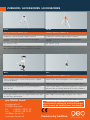
1
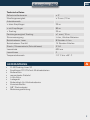
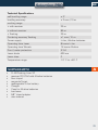
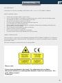
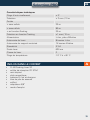
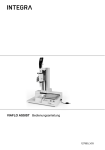
DE | EN | FR
FL 80 Tracking Liner SP
BEDIENUNGSANLEITUNG
USER MANUAL
MODE D‘EMPLOI
www.geo-fennel.com
DE
Sehr geehrter Kunde,
vielen Dank für das Vertrauen, welches Sie uns beim Erwerb Ihres neuen
geo-FENNEL-Gerätes der „Selection Pro“-Reihe entgegengebracht haben. Dieses
hochwertige Qualitätsprodukt wurde mit größter Sorgfalt produziert und qualitätsgeprüft. Im Vergleich zur bisher anerkannten guten Qualität unserer Produkte
zeichnet sich die „Selection Pro“-Reihe u.a. nun auch durch eine noch bessere
Sichtbarkeit der Laserlinien aus.
Die beigefügte Anleitung wird Ihnen helfen, das Gerät sachgemäß zu bedienen.
Bitte lesen Sie insbesondere auch die Sicherheitshinweise vor der Inbetriebnahme aufmerksam durch. Nur ein sachgerechter Gebrauch gewährleistet einen
langen und zuverlässigen Betrieb.
geo-FENNEL
Presicion by tradition.
2
Inhaltsverzeichnis
1. Lieferumfang
A
2. Bedienelemente
B
3. Bedienfeld
C
4. Empfänger FR 57-M
D
5. Stromversorgung
E
6. Gerät aufstellen
F
7. Gerät einschalten
G
8. Automatische Trackingfunktion
H
9. LED Anzeige und Tonsignale
I
10. Empfängerfunktion ohne Tracking
J
11. Hinweise / Anhang
K
DE
Technische Daten
Selbstnivellierbereich
± 3°
Nivelliergenauigkeit
± 2 mm / 10 m
Arbeitsbereich
•ohne Empfänger
30 m
•mit Empfänger
80 m
•Tracking
30 m
Zentriergenauigkeit Tracking
±1 mm / 10 m
Stromversorgung
Li-Ion, Alkaline-Batterien
Betriebsdauer Laser
8 Stunden Li-Ion
Betriebsdauer Dreifuß
15 Stunden Alkaline
Staub- / Wasserschutz (Schutzklasse)
IP 54
Laserdiode
635 nm
Laserklasse
2
Temperaturbereich
-10° C bis +45° C
LIEFERUMFANG
•
•
•
•
•
•
•
•
•
•
A
FL 80 Tracking Liner SP
Empfänger FR 57-M mit Alkalinebatterien
Bodenstativ
magnetische Zieltafel
Li-Ion-Akku
Ladegerät
Batteriefach für Alkalinebatterien
Kunststoffkoffer
5/8“-Stativadapter
Bedienungsanleitung
3
DE
B
BEDIENELEMENTE
1.
2.
3.
4.
5.
6.
7.
8.
9.
Dosenlibelle
Bedienfeld Gerät
Bedienfeld Gerätefuß
AN-/AUS-Schalter und Transportsicherung
Laseraustrittsfenster
Feinbetrieb
Batteriefach
5/8“-Adapter für Stativ
justierbare Füße
5
4
7
1
2
3
9
6
8
4
DE
C
BEDIENFELD
1.
2.
3.
4.
5.
6.
7.
AN/AUS-LED Gerät
AN/AUS vertikale Laserlinie V1
AN/AUS vertikale Laserlinie V2
AN/AUS horizontale Laserlinie H
Manuell-LED
AN/AUS Empfängerfunktion / Manuell-Funktion
LED Empfängerfunktion
1
3
2
4
7
5
6
TASTATUR GERÄTEFUSS
1. AN/AUS LED
2. AN/AUS-Taste Dreifuß
Beachte:
Wenn die AN/AUS-LED blinkt, müssen die Batterien ersetzt werden.
1
2
5
DE
D
EMPFÄNGER FR-57M
1. Dosenlibelle
2. Empfangsfenster
3. Röhrenlibelle
4. Bedienfeld
5. Anzeige Empfangsstatus
6. Seitliches Bedienfeld
7. Batteriefach (Rückseite)
8. 1/4“-Gewinde (Rückseite)
6
5
1
2
4
3
TASTATUR
1. AN/AUS Ton / Entfernung NAH/WEIT
2. LED Entfernung NAH/WEIT
3. LED AN/AUS
4. AN/AUS Empfänger
5. LED Automatikfunktion
6. Automatikfunktion
7. RECHTS
8. LINKS
6
5
7
8
1
2
3
4
BATTERIEN EINLEGEN
3 x AA Alkalinebatterien in das Batteriefach auf der Rückseite des Empfängers
einlelgen (Polarität beachten); Batteriefach verschließen.
BEDIENUNG
Zunächst die Kanalwahlschalter im Batteriefach des Empfängers und im Batteriefach des Gerätefußes auf den gleichen Kanal (1, 2 oder 3) einstellen.
Es stehen drei Kanäle zur Verfügung. Somit kann gleichzeitig mit mehreren Geräten auf einer Baustelle gearbeitet werden, ohne dass es zu Störungen kommt.
6
DE
STROMVERSORGUNG
E
Der Laser kann mit Li-Ion-Akku und alternativ mit handelsüblichen 4 x AA Alkalinebatterien betrieben werden.
Li-Ion-Akku
Der Laser ist mit einem wiederaufladbaren Li-Ion-Akkupack ausgestattet. Akkupack in das Gerät einsetzen und mit Schraube des Batteriefachs verschließen.
4 X AA ALKALINE-BATTERIEN
Der Laser kann alternativ mit Alkaline-Batterien betrieben werden.
Alkaline-Batterien in das dafür vorgesehene Fach einlegen (Polarität beachten),
das Fach in das Gerät einsetzen und Batteriefach verschließen.
7
DE
BATTERIEN IM GERÄTEFUSS
4 x AA Alkaline-Batterien in die zwei Batteriefächer am Boden des Gerätefußes
einlegen (Polarität beachten) und beide Fächer wieder verschließen.
LI-ION-AKKU LADEN
Ladegerät mit Netz und Ladebuchse am Gerät verbinden.
Der Ladezustand wird an der kleinen Lampe am Ladegerät angezeigt:
Rotes Licht zeigt an, dass der Akku geladen wird.
Grünes Licht zeigt an, dass der Akku voll geladen ist.
Der Akkupack kann auch außerhalb des Gerätes
geladen werden.
Beachte:
Wenn die AN/AUS-LED am Gerät blinkt, muss der Akku geladen werden.
F
GERÄT AUFSTELLEN
1. Auf Stativ: Gerät mit der 5/8“-Stativanzugsschraube eines handelsüblichen
Baustativs verbinden.
2. Auf dem Fußboden: Mit Bodenstativ (fest mit dem Gerät verbunden) aufstellen.
Gerät mit Hilfe der Dosenlibelle im Bedienfeld immer möglichst waagerecht aufstellen, damit die Selbstnivellierung des Gerätes einwandfrei arbeitet.
Feinjustierung durch justierbare Stativbeine vornehmen.
8
DE
FEINTRIEB
Das Gerät kann grob per Hand oder fein mit dem Feintrieb gedreht werden.
HÖHENVERSTELLBARE FÜSSE
Gegebenenfalls Dosenlibelle des Bedienfeldes mit Hilfe der 3 höhenverstellbaren
Füße des Gerätefußes einspielen, damit die maximale Genauigkeit erreicht wird.
9
DE
G
GERÄT EINSCHALTEN
AN-/AUS-Schalter in Position „ON“ bringen. Das Gerät ist nun betriebsbereit (AN/
AUS-LED leuchtet). Steht das Gerät zu schräg (außerhalb des Selbstnivellierbereiches), ertönt ein akustisches Warnsignal. Eingeschaltete Laserlinien blinken als
zusätzliche Warnung.
Zum Ausschalten AN-/AUS-Schalter wieder in Position „OFF“ stellen. Das Gerät
ist nun ausgeschaltet, und der Kompensator wird blockiert, um Beschädigungen
während des Transportes zu vermeiden.
Bevor das Gerät in den Koffer gepackt wird, AN-/AUS-Schalter immer in Position
„OFF“ stellen! Ein akustisches Warnsignal ertönt, wenn dies einmal übersehen
wurde.
EMPFÄNGER- / MANUELLFUNKTION
Das Gerät ist ausgeschaltet (OFF-Zustand).
Taste EMPFÄNGERFUNKTION / MANUELL-FUNKTION einmal drücken, um die
MANUELL-Funktion einzuschalten. Die MANUELL-LED leuchtet. Nun können die
gewünschten Laserlinien geschaltet und das Gerät in Schrägposition eingesetzt
werden.
Taste erneut drücken, um die Empfängerfunktion einzuschalten; die EmpfangsLED leuchtet. Nun kann der Empfänger FR 57-M die von Gerät ausgesendeten
Laserlinien empfangen.
Taste nochmals drücken, um das Gerät wieder auszuschalten.
10
DE
FOLGENDE LASERLINIEN KÖNNEN GESCHALTET WERDEN
H
V1
V2
H
V1
V2
AUTOMATISCHE TRACKINGFUNKTION
H
(nur möglich bei Vertikallinien)
Die automatische Trackingfunktion kann nur in Verbindung mit dem Empfänger
FR 57-M genutzt werden.
Zur Ausrichtung der Achse:
Laser über dem Bodenpunkt aufbauen
Nullposition des Empfängers FR 57-M auf den Zielpunkt ausrichten
Empfänger FR 57-M aktivieren
Die nächstgelegene vertikale Linie fährt exakt auf die Nullposition des Empfängers.
Der Empfänger FR 57-M ist gleichzeitig auch:
Normaler Empfänger zum Detektieren der horizontalen/vertikalen Laserlinien;
Fernbedienung - die Drehbewegung kann auch manuell gesteuert werden
Der FR 57-M empfängt die vom Gerät ausgesandte Laserlinie und sendet ein
Infrarotsignal an den Gerätefuß; dieser dreht sich, bis die Laserlinie exakt auf die
Nullposition des Empfängers ausgerichtet ist. (Reichweite: 30 m)
Empfänger mit Taste 2 einschalten. Ein langer Signalton ertönt, und die LEDs
links neben dem Empfangsfenster leuchten nacheinander von oben nach unten
kurz auf (oben = rot, Mitte = grün, unten = gelb). Der Empfänger ist nun im Empfangsmodus, und der Ton ist auf „leise“ gestellt. Taste 2 erneut drücken, um den
Empfänger wieder auszuschalten. Es ertönen drei kurze Signaltöne.
11
DE
Taste 1 lang gedrückt halten, um den Ton ein- und auszuschalten.
1 x lang drücken = Ton AN
(Bestätigung durch einen Piepton )
2 x lang drücken = Ton AUS
(Bestätigung durch zwei Pieptöne)
Taste 1 kurz drücken, um den Empfangsmodus zwischen NAH oder WEIT zu
wählen:
1 x kurz drücken = WEIT
(Bestätigung durch grüne LED-Anzeige)
2 x kurz drücken = NAH
(Bestätigung: LED aus)
ENTFERNUNG NAH/WEIT
Mit der Funktion ENTFERNUNG NAH/WEIT wird der Trackingradius bestimmt; z.
B. werden durch die Auswahl des Trackingradius Störungen von Geräten untereinander auf der gleichen Baustelle vermieden.
Trackingdistanz NAH = 8 - 10 m
Trackingdistanz WEIT = 30 m
Wenn die Trackingdistanz WEIT gewählt wurde, läuft der Trackingvorgang in einem
feineren Modus ab, bei Trackingdistanz NAH in einem gröberen Modus.
Wenn der FR 57-M ohne Trackingfunktion eingesetzt wird, beträgt der Arbeitsbereich 80 m. In diesem Fall ist dann die Auswahl zwischen Genauigkeit grob oder
fein nicht verfügbar.
12
DE
I
LED-ANZEIGE UND TONSIGNALE
Position Laserlinie
LED-Anzeige
Tonsignal
Sensor vorn
rot
einmal kurz
Zielpunkt
grün
lang
Sensor
gelb
zweimal kurz
Am Gerätefuß die Power-Taste drücken (LED leuchtet rot) und am Gerät den AN-/
AUS-Schalter (Transportsicherung) auf ON stellen (AN/AUS-LED leuchtet).
Nun die gewünschten Vertikallinien schalten (V1, V2) und den Laser auf Empfängsmodus AN stellen.
Empfänger FR 57-M einschalten (siehe dazu vorige Seite); das Gerät ist nun im
Empfangsmodus.
Nullposition des Empfängers auf den Zielpunkt ausrichten und am seitlichen Display AUTO einschalten; das Gerät bereitet das Tracking vor.
Automatische Trackingfunktion
Empfänger
FR 57-M
Danach mit den Pfeiltasten LINKS oder RECHTS die Trackingrichtung wählen. Der
Trackingprozess beginnt. Wenn die Laserlinie die Nullposition erreicht, ertönt ein
Dauerton, und die Anzeige des Empfangsstatus am Display leuchtet grün. Sollte
der Laser die Nullposition nicht finden, ist der Vorgang fehlgeschlagen, und der
Empfänger piept dreimal. Vorgang mit AUTO nochmals starten. Wenn der Laser die Nullmarke gefunden hat, schaltet sich die Trackingfunktion automatisch
aus, d. h. für eine neue Nullposition muss der Vorgang mit AUTO neu gestartet
werden. Während des Trackingvorgangs ertönt ein unterbrochener Piepton; bei
Erreichen der Nullposition ertönt ein Dauerton.
13
DE
Wenn während des Trackingvorgangs eine Pfeiltaste gedrückt wird (rechts oder
links), startet der Vorgang von vorn.
Beachte:
Wenn die Laserlinie bereits das Empfangsfenster des Empfängers erreicht hat
und eine Pfeiltaste gedrückt wird, ändert sich die Rotationsrichtung des Gerätefußes.
Zum Energiesparen kann der Gerätefuß nach vollendetem Trackingprozess ausgeschaltet werden.
Beachte:
Wenn 10 Minuten lang keine Anwendung durchgeführt wird, schaltet sich der
Gerätefuß automatisch aus (Energiesparfunktion).
MANUELLER EINSATZ
Die Drehbewergung kann auch manuell gesteuert werden. Der Empfänger dient
als Fernbedienung. Dazu die AUTO-Taste drücken, um die Automatikfuntion auszuschalten. Nun mit den Pfeiltasten den Gerätefuß nach rechts oder links drehen.
Durch längeres Gedrückthalten der Pfeiltasten erhöht sich die Rotationsgeschwindigtkeit des Dreifußes.
14
DE
EMPFÄNGERFUNKTION OHNE TRACKING
J
Der Empfänger FR 57-M kann horizontal nur manuell verwendet werden, d. h.
es erfolgt nur die Höhenanzeige (grüne LED und Dauerton). Horizontal ist keine
Trackingfunktion möglich.
•
•
•
•
•
Höhenanzeige durch 3-fach LED vorn, hinten und seitlich
Abschaltbarer Ton
2 Entfernungs- / Genauigkeitsstufen
Abschaltautomatik
3 x AA Alkalinebatterie
BEDIENUNG
Empfänger einschalten (siehe BEDIENUNG mit Trackingfunktion) und am Gerät
die Empfängerfunktion aktivieren.
Zum Empfangen des Laserstrahls den Empfänger langsam
auf und ab bewegen.
Empfang des Laserstrahls und entsprechende Anzeige durch die LEDs (Vorder-, Rückseite, Seite):
A
Empfänger nach unten bewegen
Akustisches Signal: schneller Piepton
BEmpfänger nach oben bewegen
Akustisches Signal: langsamer Piepton
CKorrekte Bezugshöhe
Akustisches Signal: Dauerton
15
DE
K
HINWEISE / ANHANG
PRÜFUNG DER NIVELLIERGENAUIGKEIT
Gerät in der Mitte zwischen zwei Wänden aufstellen, die ungefähr 5 m voneinander entfernt sind.
Laserkreuz auf Wand markieren. Gerät um 180° drehen und Laserkreuz markieren.
Gerät etwa 0,6 m von Wand A aufstellen und Markierungen, wie vorstehend beschrieben, wiederholen. Wenn die Differenz zwischen den ersten beiden Messungen (mit gleichen Zielweiten) und den
letzten beiden Messungen (mit unterschiedlichen Zielweiten) 3 mm nicht überschreitet, liegt Ihr Gerät
innerhalb der Toleranz.
Prüfung der Genauigkeit der horizontalen Linie (Ende zu Ende)
Gerät ca. 5 m von Wand aufstellen und Laserkreuz an Wand markieren. Gerät drehen und Laserkreuz
ca. 2,5 m nach links schwenken und überprüfen, ob waagerechte Linie ± 2 mm auf der gleichen Höhe
mit dem markierten Kreuz liegt. Vorgang durch Schwenken des Gerätes nach rechts wiederholen.
Prüfung der Genauigkeit der vertikalen Linie (Ende zu Ende)
Gerät ca. 5 m von Wand aufstellen. An dieser Wand ein Lot mit Schnur von ca. 2,5 m Länge befestigen. Die vertikale Linie auf die Lotschnur richten. Die Genauigkeit liegt innerhalb der Toleranz, wenn
die Abweichung der vertikalen Linie (von oben bis unten) nicht größer als ± 1,5 mm ist.
UMSTÄNDE, DIE DAS MESSERGEBNIS VERFÄLSCHEN KÖNNEN
Messungen durch Glas- oder Plastikscheiben; verschmutzte Laseraustrittsfenster; Sturz oder starker
Stoß. Bitte Genauigkeit überprüfen.
Große Temperaturveränderungen: Wenn das Gerät aus warmer Umgebung in eine kalte oder umgekehrt gebracht wird, vor Benutzung einige Minuten warten.
UMGANG UND PFLEGE
Messinstrumente generell sorgsam behandeln. Nach Benutzung mit weichem Tuch reinigen (ggfs.
Tuch in etwas Wasser tränken). Wenn das Gerät feucht war, sorgsam trocknen. Erst in den Koffer oder
die Tasche packen, wenn es absolut trocken ist. Transport nur in Originalbehälter oder -tasche.
ELEKTROMAGNETISCHE VERTRÄGLICHKEIT
Es kann nicht generell ausgeschlossen werden, dass das Gerät andere Geräte stört (z.B. Navigationseinrichtungen); durch andere Geräte gestört wird (z.B. elektromagnetische Strahlung bei erhöhter
Feldstärke z.B. in der unmittelbaren Nähe von Industrieanlagen oder Rundfunksendern).
16
DE
CE-KONFORMITÄT
Das Gerät hat das CE-Zeichen gemäß den Normen EN 61010-1:2001 + corr- 1+2, IEC 60825-1:2008-05
WARN- UND SICHERHEITSHINWEISE
•
•
•
•
•
•
•
•
•
•
Richten Sie sich nach den Anweisungen der Bedienungsanleitung.
Anleitung vor Benutzung des Gerätes lesen.
Blicken Sie niemals in den Laserstrahl, auch nicht mit optischen Instrumenten. Es besteht die
Gefahr von Augenschäden.
Laserstrahl nicht auf Personen richten.
Die Laserebene soll sich über der Augenhöhe von Personen befinden.
Niemals das Gehäuse öffnen. Reparaturen nur vom autorisierten Fachhändler durchführen lassen.
Keine Warn- oder Sicherheitshinweise entfernen.
Lasergerät nicht in Kinderhände gelangen lassen.
Gerät nicht in explosionsgefährdeter Umgebung betreiben.
Diese Gebrauchsanleitung ist aufzubewahren und bei Weitergabe der Lasereinrichtung mitzugeben.
LASERKLASSIFIZIERUNG
Das Gerät entspricht der Lasersicherheitsklasse 2 gemäß der Norm DIN IEC 60825-1:2008-05. Das
Gerät darf ohne weitere Sicherheitsmaßnahmen eingesetzt werden. Das Auge ist bei zufälligem,
kurzzeitigem Hineinsehen in den Laserstrahl durch den Lidschlussreflex geschützt.
Laserwarnschilder der Klasse 2 sind gut sichtbar am Gerät angebracht.
Bitte unbedingt beachten:
Wenn Sie Geräte zur Reparatur / zur Justage an uns zurücksenden,
entnehmen Sie bitte unbedingt aus Sicherheitsgründen Akkus oder
Batterien aus dem Gerät!
Danke.
17
DE
GARANTIE
Die Garantiezeit beträgt zwei (2) Jahre, beginnend mit dem Verkaufsdatum. Die Garantie erstreckt
sich nur auf Mängel wie Material-oder Herstelungsfehler, sowie die Nichterfüllung zugesicherter
Eigenschaften. Ein Garantieanspruch besteht nur bei bestimmungsgemäßer Verwendung. Mechanischer Verschleiß und äußerliche Zerstörung durch Gewaltanwendung und Sturz unterliegen nicht der
Garantie. Der Garantieanspruch erlischt, wenn das Gehäuse geöffnet wurde. Der Hersteller behält
sich vor, im Garantiefall die schadhaften Teile instand zusetzen bzw. das Gerät gegen ein gleiches oder
ähnliches (mit gleichen technischen Daten) auszutauschen. Ebenso gilt das Auslaufen der Batterie
nicht als Garantiefall.
HAFTUNGSAUSSCHLUSS
1.
2.
3.
4.
5.
6.
18
Der Benutzer dieses Produktes ist angehalten, sich exakt an die Anweisungen der Bedienungsanleitung zu halten. Alle Geräte sind vor der Auslieferung genauestens überprüft worden. Der Anwender sollte sich trotzdem vor jeder Anwendung von der Genauigkeit des Gerätes überzeugen.
Der Hersteller und sein Vertreter haften nicht für fehlerhafte oder absichtlich falsche Verwendung
sowie daraus eventuell resultierende Folgeschäden und entgangenen Gewinn.
Der Hersteller und sein Vertreter haften nicht für Folgeschäden und entgangenen Gewinn durch
Naturkatastrophen wie z.B. Erdbeben, Sturm, Flut, usw. sowie Feuer, Unfall, Eingriffe durch Dritte
oder einer Verwendung außerhalb der üblichen Einsatzbereiche.
Der Hersteller und sein Vertreter haften nicht für Schäden und entgangenen Gewinn durch geänderte oder verlorene Daten, Unterbrechung des Geschäftsbetriebes usw., die durch das Produkt
oder die nicht mögliche Verwendung des Produktes verursacht wurden.
Der Hersteller und sein Vertreter haften nicht für Schäden und entgangenen Gewinn resultierend
aus einer nicht anleitungsgemäßen Bedienung.
Der Hersteller und sein Vertreter haften nicht für Schäden, die durch unsachgemäße Verwendung
oder in Verbindung mit Produkten anderer Hersteller verursacht wurden.
DE
NOTIZEN
19
EN
Dear customer,
Thank you for your confidence having purchased a geo-FENNEL instrument of
„Selection Pro“ series. This high-quality product was produced and tested with
due prudence.
Among others „Selection Pro“ is defined by even clearer visible lines which you
are originally used to from our standard range of instruments.
This manual will help you to operate the instrument appropriately. Please read
carefully - particularly the safety instructions. A proper use guarantees a longtime
and reliable operation.
geo-FENNEL
Precision by tradition.
20
Inhaltsverzeichnis
1. Supplied with
A
2. Operational elements
B
3. Keypad
C
4. Receiver FR 57-M
D
5. Power supply
E
6. Set up
F
7. Switch on
G
8. Automatic Tracking function
H
9. LED and sound indication
I
10. Use of receiver without Tracking function
J
11. Information / annex
K
EN
Technical Specifications
self-levelling range
± 3°
levelling accuracy
± 2 mm / 10 m
working range
•with receiver
30 m
•without receiver
80 m
•Tracking
30 m
Centering accuracy Tracking
±1 mm / 10 m
Power supply
Li-Ion, Alkaline batteries
Operating time Laser
8 hours Li-Ion
Operating time Tribrach
15 hours Alkaline
Dust / water protection
IP 54
Laser diode
635 nm
Laser class
2
Temperature range
-10° C to +45° C
SUPPLIED WITH
•
•
•
•
•
•
•
•
•
•
A
FL 80 Tracking Liner SP
receiver FR 57-M with Alkaline batteries
floor tripod
magnetic Target
rechargeable Li-Ion battery
Charger
Case for Alkaline batteries
hard case
5/8“ tripod adapter
user manual
21
EN
B
OPERATIONAL ELEMENTS
1.
2.
3.
4.
5.
6.
7.
8.
9.
Circular bubble
Keypad of instrument
Keypad of base
ON/OFF knob / transport lock
Laser emitting windows
Fine adjustment screw
Battery compartment
5/8“ thread for tripod
Adjustable support leg
5
4
7
1
2
3
9
6
8
22
EN
C
KEYPAD
1.
2.
3.
4.
5.
6.
7.
ON/OFF vertical laser line V1
ON/OFF LED instrument
ON/OFF vertical laser line V2
ON/OFF horizontal laser line H
MANUAL LED
ON/OFF receiver mode / MANUAL function
LED receiver mode
1
3
2
4
7
5
6
KEYPAD BASE
1. ON/OFF LED
2. ON/OFF button tribrach
Note:
If the ON/OFF LED flashes the batteries must be replaced.
1
2
23
EN
D
RECEIVER FR-57M
1.
2.
3.
4.
5.
6.
7.
8.
Circular bubble
Receiving window
Tube vial
Keypad
Receiving status indication
Side keypad
Battery case (back)
1/4“-thread (back)
6
5
1
2
4
3
KEYPAD
1. ON/OFF sound / SHORT/LONG
distance
2. LED SHORT/LONG distance
3. LED ON/OFF
4. ON/OFF receiver
5. LED Automatic function
6. Automatic function
7. RIGHT
8. LEFT
6
5
7
8
1
2
3
4
INSERT BATTERIES
Put in 3 x AA Alkaline batteries into the battery case (take care to polarity) on the
back; close battery case.
OPERATION
First adjust the channel switch of the laser and the receiver to the same channel
(you will find them in the battery case of the receiver and of the base). Three
channels (1, 2 and 3) are available. By using different channels several instruments can be operated on one construction site without any disturbances.
24
EN
POWER SUPPLY
E
Both the standard Li-Ion battery or 4 x AA Alkaline batteries can be used.
Li-Ion battery pack
FL 80 SP comes with Li-Ion rechargeable battery pack. Mount the rechargeable
battery box and close the battery compartment with the battery box screw.
4 X AA AKALINE BATTERIES
FL 80 SP can be used with Alkaline batteries alternatively.
Put in Alkaline batteries into Alkaline battery case (take care to polarity), put case
into the laser and lock the battery compartment.
25
EN
BATTERIES OF THE BASE
Put in 4 x AA Alkaline batteries into the two Alkaline battery cases on the bottom
of the base (take care to polarity) and lock both battery compartments.
CHARGE LI-ION BATTERY PACK
Connect the charger with the socket.
Red light at the charger indicates that batteries are being charged.
Green light at the charger indicates that batteries are fully charged.
The Li-Ion battery pack can be charged outside of the laser.
Note:
If the ON/OFF LED of the instrument flashes the battery must be charged.
F
SET UP THE INSTRUMENT
1. On a tripod: Connect the laser the to 5/8“ retaining bolt of builder‘s tripod.
2. On the floor: Set up the laser on the floor tripod.
Set up the instrument as upright as possible by means of the circular vial of the
keypad to allow the self-levelling system to function within the range.
Fine adjustment with adjustable tripod legs.
26
EN
FINE ADJUSTMENT SCREW
The laser can be rotated by hand or carefully by use of the tangent screw.
HEIGHT ADJUSTABLE SUPPORT LEGS
If necessary centre the circular bubble of the keypad by means of height
adjustable support legs in order to reach maximum accuracy.
27
EN
G
POWER ON THE INSTRUMENT
Set ON/OFF knob to position „ON“. The instrument is now ready for use (ON/OFF
LED is illuminated). An audible and optical (blinking lines) alarm indicates when
the instrument was set up outside of the compensator range. Set up the instrument on a more even surface.
To switch off the instrument bring ON/OFF knob in position „OFF“. The instrument
is now switched off and the compensator is blocked to avoid damages during
transport.
NOTE: During transport ON/OFF knob (compensator clamp) must be set to „OFF“.
Disregard may lead to damages of the compensator.
RECEIVER / MANUAL FUNCTION
The instrument is switched off (OFF position).
Press button RECEIVER MODE / MANUAL FUNCTION once to enter into the
MANUAL function. The MANUAL LED is illuminated. Now the required laser lines
can be switched and the instrument can be used in slope position.
Press this button again to switch on the receiver function. The receiving LED is
illuminated. Now the receiver FR 57-M can detect the laser lines projected from
the instrument.
Press the button once more in order to switch off the instrument.
28
EN
FOLLOWING LASER LINES CAN BE PROJECTED:
H
V1
V2
H
V1
V2
AUTOMATIC TRACKING FUNCTION
H
(Available for vertical laser lines only)
The automatic tracking function is ony effective together with receiver FR 57-M.
For the axis-alignment:
Position the laser over the ground point
Postion on-grade-mark of receiver FR 57-M at the target point
Activate receiver FR 57-M
The closest vertical laser line moves to the on-grade-position of the receiver automatically
The receiver FR 57-M can also be used as:
Normal receiver detecting the horizontal/vertical laser lines
Remote control to operate the horizontal movement manually
The FR 57-M receives the laser line signal from the instrument and sends out an
infrared remote command to the instrument base. The base rotates until the laser
line is exactly centered to the on-grade position of the receiver. (Range: 30 m).
Switch on the receiver by pressing button 2. A long beep will sound and the LEDs
on the left side of the receiving window will flash one after the other (top = red,
middle = green, bottom = yellow). Now the receiver is in receiving mode and
the sound is in low volume. Press button 2 again to switch off the receiver. Three
short beeps will sound.
29
EN
Press button 1 long to switch on or off the signal tone.
Press 1 x long for sound ON
Confirmation: one beep)
Press 2 x long for sound OFF
(Confirmation: two beeps)
Press button 1 short to select SHORT distance or LONG distance receiving mode
Press 1 x short for LONG
(Confirmation: green LED indication)
Press 2 x short for SHORT
(Confirmation: LED off)
DISTANCE SHORT/LONG
With the function DISTANCE SHORT/LONG the radius of the tracking function
will be determined;
i. e. by selecting the tracking radius of the instrument interactions of several
instruments on the same contruction sites will be avoided.
Tracking distance SHORT = 8 - 10 m
Tracking distance LONG = 30 m
In case the tracking distance LONG was selected the tracking procedure will run
in a fine mode; in case of selecting tracking distance SHORT the tracking mode
will be coarse.
30
EN
I
LED AND SOUND INDICATION
Position laser line
LED indication
Sound
Sensor front
red
single short
Central position
green
long
Sensor
yellow
twice short
Switch on the base by pressing the power button (LED will light red) and the
instrument by turning the ON/OFF knob (transport lock) to ON (ON/OFF LED
will light red). Now select the required vertical lines (V1, V2) and switch on the
receiving mode at the laser. Switch on receiver FR 57-M (see previous page); now
the instrument is in receiving mode. Position on-grade-mark of the receiver at the
target point and press the AUTO button for automatic tracking; the instrument will
now prepare the tracking.
Automatic tracking function
Receiver
FR 57-M
Select the tracking direction (RIGHT or LEFT) with the arrow buttons. Now the
tracking procedure will start. When the laser line is in on-grade position a permanent beep will sound and the centre LED will light green. In case the laser line
does detect the on-grade mark the procedure has failed and the receiver beeps
three times. Re-start the procedure by pressing AUTO again. When the laser line
is in on-grade position the tracking function automatically stops, i. e. for a new
on-grade position the procedure has to be started again by pressing AUTO. During
the tracking procedure a discontinued beep will sound; when the laser line is in
on-grade position a permanent beep will sound.
31
EN
In case one of the arrow buttons (left or right) is used during the tracking procedure same will re-start from the beginning.
Note:
When the laser line is already in the receiving window of the receiver and an
arrow button is used the tracking direction of the base will change.
In order to save battery power the base can be switched off when the tracking
procedure is finished.
Note:
If the instrument is not operated for more than 10 minutes the base will automatically switch off (in order to save battery power).
MANUAL OPERATION
The rotation can also be controlled manually. The receiver is then used as remote
control.
Press the AUTO button to switch off the automatic tracking function. Now the
base can be rotated with the right or left arrow button. If the buttons are pressed
longer the rotation speed of the base will increase.
32
EN
USE OF RECEIVER WITHOUT TRACKING FUNCTION
J
In horizontal direction the receiver FR 57-M can be used manually, i. e. there is
only a height indication (green LED and permanent beep). In horizontal direction
the automatic tracking function is not available.
Height indication by 3 LEDs which are on the front, side and back
Shut-off tone
2-step distance / accuracy mode
Automatic shut-off
3 x AA Alkaline batteries
OPERATION
Switch the receiver on (see OPERATION with tracking function). Activate receiver
funtction of the laser
Move the receiver up and down carefully to detect the
laser beam.
Detection of laser signal:
A Move the receiver down
Acoustic signal: ultra-short frequent beep
BMove the receiver up
Acoustic signal: short frequent beep
C On level
Acoustic signal: continuous beep
33
EN
K
USE RECEIVER WITHOUT TRACKING
ACCURACY CHECK
Set up instrument in the middle of two walls which are about 5 m apart. Mark visible laser cross on
one wall. Turn unit to opposite wall and mark laser cross.
Repeat measurements with distance of about 0,6 m to one wall and about 4,4 m to second wall.
Deviation between two measurements taken from the centre and two measurements taken at 0,6 m
and 4,4 m must not exceed 3 mm.
Testing accuracy of horizontal line (end to end)
Set up instrument about 5 m from a wall. Mark laser cross on wall. Turn instrument until the laser
cross has moved about 2,5 m to the left side and check if horizontal line is within ± 2 mm of laser
cross marked on wall. Repeat measurement by turning instrument to the right side
Testing accuracy of vertical line (end to end)
Set up instrument about 5 m from a wall. Fix a plumb line of 2,5 m length to the wall, using a plumb
bob. Bring laser line into coincidence with the plumb line. Deviation between laser line and plummet
cord from top to bottom must not exceed ± 1,5 mm.
SPECIFIC REASONS FOR ERRONEOUS MEASURING RESULTS
Measurements through glass or plastic windows; dirty laser emitting windows; after instrument has
been dropped or hit. Please check accuracy.
Large fluctuation of temperature: If instrument will be used in cold areas after it has been stored in
warm areas (or the other way round) please wait some minutes before carrying out measurements.
CARE AND CLEANING
Handle measuring instruments with care. Clean with soft cloth only after any use. If necessary damp
cloth with some water. If instrument is wet clean and dry it carefully. Pack it up only if it is perfectly
dry. Transport in original container / case only.
ELECTROMAGNETIC ACCEPTABILITY (EMC)
It cannot be completely excluded that this instrument will disturb other instruments (e.g. navigation
systems); will be disturbed by other instruments (e.g. intensive electromagnetic radiation nearby
industrial facilities or radio transmitters).
34
EN
CE-CONFORMITY
Instrument has CE-mark according to EN 61010-1:2001 + corr. 1+2, IEC 60825-1:2008:05.
SAFETY INSTRUCTIONS
•
•
•
•
•
•
•
•
•
•
Follow up instructions given in user manual.
Do not stare into beam. Laser beam can lead to eye injury. A direct look into the beam (even
from greater distance) can cause damage to your eyes.
Do not aim laser beam at persons or animals.
The laser plane should be set up above eye level of persons.
Use instrument for measuring jobs only.
Do not open instrument housing. Repairs should be carried out by authorized workshops only.
Please contact your local dealer.
Do not remove warning labels or safety instructions.
Keep instrument away from children.
Do not use instrument in explosive environment.
The user manual must always be kept with the instrument.
LASER CLASSIFICATION
The instrument is a laser class 2 laser product according to DIN IEC 60825-1:2008-05. It is allowed to
use unit without further safety precautions. Eye protection is normally secured by aversion responses
and the blink reflex.
The laser instrument is marked with class 2 warning labels.
Please note:
If you return instruments for repair / for adjustment to us please
disconnect batteries or rechargeable batteries from the instrument - this
is for safety reasons!
Thank you.
35
EN
WARRANTY
This product is warranted by the manufacturer to the original purchaser to be free from defects in
material and workmanship under normal use for a period of two (2) years from the date of purchase.
During the warranty period, and upon proof of purchase, the product will be repaired or replaced (with
the same or similar model at manufacturers option), without charge for either parts or labour. In case
of a defect please contact the dealer where you originally purchased this product. The warranty will
not apply to this product if it has been misused, abused or altered. Without limiting the foregoing,
leakage of the battery, bending or dropping the unit are presumed to be defects resulting from misuse
or abuse.
EXCEPTIONS FROM RESPONSIBILITY
1.
2.
3.
4.
5.
6.
36
The user of this product is expected to follow the instructions given in operators’ manual.
Although all instruments left our warehouse in perfect condition and adjustment the user is
expected to carry out periodic checks of the product’s accuracy and general performance.
The manufacturer, or its representatives, assumes no responsibility of results of a faulty or
intentional usage or misuse including any direct, indirect, consequential damage, and loss of
profits.
The manufacturer, or its representatives, assumes no responsibility for consequential damage,
and loss of profits by any disaster (earthquake, storm, flood etc.), fire, accident, or an act of a
third party and/or a usage in other than usual conditions.
The manufacturer, or its representatives, assumes no responsibility for any damage, and loss of
profits due to a change of data, loss of data and interruption of business etc., caused by using
the product or an unusable product.
The manufacturer, or its representatives, assumes no responsibility for any damage, and loss of
profits caused by usage other than explained in the users‘ manual.
The manufacturer, or its representatives, assumes no responsibility for damage caused by wrong
movement or action due to connecting with other products.
EN
NOTES
37
FR
Cher client,
Nous tenons à vous remercier pour la confiance que vous nous avez témoignée,
par l‘acquisition de votre nouvel instrument geo-FENNEL de la série
„Selection Pro“. Ce produit de qualité de haut de gamme a été fabriqué avec le
plus grand soin et vérifié quant à sa qualification. Outre la bonne qualité qui faisait
jusqu‘ici la renommée de nos produits, la série „Selection Pro“ est également
caractérisée par une amélioration notable de la visibilité des lignes laser.
Les instructions de service ci-jointes vous aideront à vous servir de votre instrument de manière adéquante. Nous vous recommandons de lire avec soin tout
partiqulièrement les consignes de sécurité de ladite notice avant la mise en
service de votre appareil. Un emploi approprié est l‘unique moyen de garantir un
fonctionnement efficace et de longue durée.
geo-FENNEL
Precision by tradition.
38
Inhaltsverzeichnis
1. Inclus dans le coffret
A
2. Description
B
3. Clavier du laser
C
4. Cellule de réception FR 57-M
D
5. Battérie et chargeur
E
6. Installation du laser
F
7. Allumer l‘appareil
G
8. Fonction Tracking automatique
H
9. Indication LED et son
I
10. Utilisation de la cellule sans Tracking
J
11. Notices / annexes
K
FR
Caractéristiques techniques
Plage d‘auto nivellement
± 3°
Précision
± 2 mm / 10 m
Portée
•sans cellule
30 m
•avec cellule
80 m
•en fonction Tracking
30 m
Précision en fonction Tracking
±1 mm / 10 m
Alimentation
Li-Ion, piles d‘Alkaline
Autonomie du laser
8 heures Li-Ion
Autonomie du support motorisé
15 heures Alkaline
Étanchéité
IP 54
Diode laser
635 nm
Classe du laser
2
Plage de température
-10° C à +45° C
INCLUS DANS LE COFFRET
•
•
•
•
•
•
•
•
•
A
FL 80 Tracking Liner SP
cellule de réception FR 57-M
mini-trépied
cible magnétique
batteries Li Ion et chargeur
bloc de pile de secours
coffret
adaptateur 5/8‘‘
mode d‘emploi.
39
FR
B
DESCRIPTION
1.
2.
3.
4.
5.
6.
7.
8.
9.
Nivelle circulaire
Clavier d‘instrument
Clavier du support
Bouton ON/OFF / verouillage pour transport
Vitre protection du laser
Molette de reglage fin
Compartiment piles
Filetage 5/8“
Pieds adjustables
5
4
7
1
2
3
9
6
8
40
FR
C
CLAVIER DU LASER
1.
2.
3.
4.
5.
6.
7.
Bouton ON/OFF de la verticale V1
Diode ON/OFF du laser
Bouton ON/OFF de la verticale V2
Bouton ON/OFF de l‘horizontale H
Diode du mode MANUEL
Bouton fonction cellule / mode MANUEL
Diode fonction cellule
1
3
2
4
7
5
6
CLAVIER DU SUPPORT
1. Diode ON/OFF
2. Bouton ON/OFF
Attention:
Si le bouton ON/OFF clignotte, les piles doivent etre remplacees.
1
2
41
FR
D
CELLULE DE RECEPTION FR 57-M
1.
2.
3.
4.
5.
6.
7.
8.
Nivelle circulaire
Fenêtre de reception
Nivelle
Clavier
Indicateur de positionnement
Clavier fonction Tracking
Compartiment piles (derriere)
Filetage 1/4“
6
5
1
2
4
3
CLAVIER
1. Bouton reglage du son et reglage
courte / longue distance reception
2. Diode indication courte / longue
3. Diode ON/OFF
4. Bouton ON/OFF
5. Diode mode Tracking
6. Bouton fonction Tracking
7. DROITE
8. GAUCHE
6
5
7
8
1
2
3
4
PILES
Mettre 3 x AA piles alcalines dans le compartiment piles (attention à la polarité) et
refermer le compartiment.
SYNCHRONISATION
Tout d‘abord, mettre le laser et la cellule sur le même canal (vous trouverez le
bouton dans le compartiment piles de la cellule et de l‘embase). 3 canaux (1, 2
est 3) sont disponibles. De ce fait plusieurs instruments peuvent travailler simultanément sur le même site sans être perturbes.
42
FR
BATTERIE ET CHARGEUR
E
Le laser fonctionne aussi bien sur batterie que sur piles.
Pack accus Li Ion
Le FL 80 SP est livré avec des battéries rechargeables Li Ion. Placez le pack accu
au dos du laser, puis verrouillez le à l‘aide la vis.
4 X AA PILES ALCALINE
Le FL 80 SP fonctionne également avec des piles alcalines.
Mettre les piles dans le compartiment bloc de piles de secours (attention à la
polarité), placez au dos du laser et verreouillez à l‘aide de la vis.
43
FR
PILES DU SUPPORT
Mettre 4x AA piles alcalines dans les compartiments piles prevus à cet effet (attention à la polarité) er refermez bien les 2 compartiments.
CHARGE DU PACK BATTERIE LI-ION
Connectez le chargeur sur la battérie grâce à la fiche.
Quand la lumière rouge est allumée, cela signifie que la battérie est en charge.
Quand la lumière verte est allumée, cela signifie que la battérie est chargée.
Le pack accu Li-Ion peut être chargé independament du laser.
Si la diode ON/OFF du laser clignotte, alors la battérie doit être chargée.
F
INSTALLATION DU LASER
1. Sur un trépied: Vissez le laser sur la pompe de filetage 5/8“ du trépied.
2. Sur le sol: Installez le laser sur le mini trépied fourni de serie.
Installez le laser le plus droit possible en centrant la vielle dans son cercle pour
permettre au laser de fonctionner en etant dans sa plage de compensation.
Il est possible d‘adjuster le laser grâce à ses pieds reglables.
44
FR
MOLETTE DE REGLAGE FIN
Le laser pivote sur son socle manuellement avec la main ou vous pouvez utiliser
la molette sur le côte pour un réglage fin.
PIEDS REGLABLES
Pour centrer la nivelle dans son cercle, vous pouvez utiliser les pieds réglables
pour bénéficier d‘une grande précision de réglage.
45
FR
G
ALLUMER L‘APPAREIL
Mettre le bouton en position ON. L‘instrument est maintenant prêt à être utilisé
(la diode ON/OFF doit être allumée). Un signal sonore et lumineux (les lignes
clignotent) indique si l‘instrument est en dehors de sa plage de compensation. Si
c‘est le cas, placez l‘instrument sur une surface plus plane.
Pour arrêter l‘instrument, mettre le bouton ON/OFF sur la position OFF.
L‘instrument est maintenant éteint et le compensateur est bloqué afin de le protéger pendant le transport.
Attention:
Pendant le transport le bouton ON/OFF doit être mis en position OFF. Ceci afin
d‘éviter d‘endommager le compensateur pendant le transport.
FONCTION CELLULE / MODE MANUEL
L‘instrument es en position OFF.
Presser le bouton de MODE CELLULE / FONCTION MANUEL pour enclencher la
fonction manuelle. La diode à côté du picto manuel doit être maintenant allumée.
Les lignes peuvent être allumées et le laser peut travaillver dans toutes les positions.
Appuyer encore une fois sur le bouton pour enclencher le mode cellule. La diode
à côté du picto (P) doit être allumée. Maintenant la cellule peut détecter les lignes
du laser.
Appuyer sur le bouton une fois de plus pour éteindre l‘appareil.
46
FR
TOUTES LES LIGNES CI DESSOUS PEUVENT ÊTRE PROJETER
H
V1
V2
H
V1
V2
FONCTION TRACKING AUTOMATIQUE
H
(Disponible pour les lignes verticales seulement)
La fonction Tracking ne peut fonctionner qu‘avec la cellule FR 57-M.
Pour alignement des axes:
Positionner le laser sur le pint de référence au sol que vous aveu determiné.
Allumer la cellule FR 57-M.
La ligne verticale la plus proche va s‘aligner directement sur la cellule.
La cellule FR 57-M peut aussi être utiliesée comme:
Cellule normale pour détecter les lignes verticales et horizontales. Télécommande
pour bouger le laser horizontalement.
La cellule FR 57-M capte le signal du laser et envoie une commande par infrarouge à l‘embase. L‘embase va pivoter jusqu‘à ce que la ligne verticale du laser soit
parfaitement centrée sur la cellule (jusqu‘à une portée de 30 m maxi).
Allumer la cellule en appuyant sur le bouton 2. Un long bip va sonner et la diode
sure le côté gauche de la fenêtre de la cellule va clignoter de toutes les couleurs
(rouge, vert et jaune). Maintenant la cellule est en mode détection et le son est
réeglé en niveau bas. Presser le bouton 2 une deuxième fois pour éteindre la
cellule. 3. Petits bip vont sonner.
47
FR
Presser le bouton 1 longuement pour allumer le son (1 bip va retentir).
Appuyer longuement 2 fois sur le bouton pour éteindre le son (2 bip vont retentir)
Presser le bouton 1 brievement pour sélectionner le mode COURTE / LONGUE
distance.
Presser le bouton 1 fois brievement pour le mode longue distances (la diode vert
s‘allumer)
Presser brievement 2 fois le bouton pour le mode COURTE DISTANCE. La diode
doit s‘éteindre.
MODE COURTE / LONGUE DISTANCE
Avec la fonction COURTE / LONGUE DISTANCE le rayon d‘action va être determiné. Cela permet d‘adapter le rayon d‘action et de ne pas être pollué par d‘autres
instruments qui travailleraient sur le même site.
Fonction Tracking COURTE DISTANCE = 8 à 10 m
Fonction Tracking LONGUE DISTANCE = jusqu‘à 30 m
Dans le cas où le mode distance longue est sélectionne, le mode tracking va fonctionner en mode fins; si le mode DISTANCE COURTE est selectionnée le mode
Tracking va fonctionner en mode plus rapide.
48
FR
I
INDICATION LED ET SON
Position ligne laser
Indication LED
Son
Senseur devant
rouge
bip court
Position centrale
vert
long
Senseur
jaune
2 bip court
Allumez la base en pressant le bouton ON sur l‘embase (la diode rouge doit
s‘allumer) et deverouiller le compensateur en le mettant sur la position ON (la
diode ON/OFF doit s‘allumer aussi en rouge).
Maintenant sélectionnez la ou les lignes verticales que vous voulez utiliser (V1,
V2) et allumez le mode pulse sur le laser. Allumer la cellule de reception FR 57-M
(voir page précédente).
L‘instrument est désormais en mode détection. Positionnez le répère de la cellule
sur le point de répère au mur et appuyet sur le bouton AUTO pour activer le tracking automatique. L‘instrument va détecter et s‘aligner automatiquement sur la
cellule.
Fonction automatique Tracking
cellule
FR 57-M
Sélectionnez la direction dans laquelle vous voulez que le laser tourne pour
détecter la cellule avec les boutons flèche correspondants. Le tracking est alors
activé. Quand la ligne du laser est parfaitement alignnée sur la cellule, un bip continu retentit et la diode de couleur verte s‘allume. Dans le cas où la ligne n‘est pas
parfaitement alignée, la cellule bip 3 fois. Il faut alors recommencer en pressant le
bouton AUTO une nouvelle fois. Quand le laser est mis en MANUEL, la fonction
Tracking s‘arrête automatiquement. Pour la réactiver il faut recommencer la procédure en appuyant de noveau sur auto. Pendant la procédure de tracking, un bip
discontenu va sonner. Quand le laser s‘est aligné, le bip devient continu.
49
FR
Si on touche aux boutons flèche pendandt la procédure de tracking, alors il faut
recommencer la procédure au début.
Attention:
Quand la ligne laser est déjà alignée sur la fenêtre de réception de la cellule et
que l‘on touche aux boutons flèche, le laser va tourner et se décaler d‘une ligne.
Attention:
Si l‘instrument n‘a pas été manipulé pendant 10 minutes, l‘embase s‘éteint automatiquement pour sauvegarder les piles.
MODE MANUEL
Le laser peut également tourner manuellement sur son embase. La cellule est
alors utilisée comme télécomande. Appuyez sur le bouton AUTO pour stopper
la fonction Tracking automatique. Maintenant l‘embase peut être tournée vers la
gauche ou la droite grâce aux boutons flèche. Si on arrête appuyer sur les boutons flèches. La rotation s‘effectuera rapidement.
50
FR
UTILITSATION DE LA CELLULE SANS TRACKING
J
En mode horizontal, la cellule FR 57-M ne peut être utilisée qu‘en fonctionnement
normale. La fonction tracking ne fonctionnant qu‘en mode vertical.
3 diodes d‘indication de hauteur qui sont devant, sur le côté et derrière la cellule
mode silencieux
2 niveaux de réglage de distance et de précision
arret automatique
3 x piles AA alcalines
FONCTIONNEMENT
Allumer la cellule (voir chapitre FONCTION TRACKING). Activez le mode réception
(pulse) sur le laser.
Bouger lentement la cellule de haut en bas pour détecter
le faicseau laser.
Detection du signal du laser:
A Baisser la cellule
Bip sonore très court
B Lever la cellule
bip sonore court
C Parfaitement de niveau
signal sonore continu
51
FR
K
NOTICES / ANNEXES
CONTROLLER LA PRÉCISION
Poser l‘appareil au milieu de deux murs d‘une distance d‘à peu près 5m. Faire une marque visible sur
le mur à l‘endroit où la croix laser est projetée. Tournez l‘appareil à 180° pourvoir si les croix sont bien
alignées sur les marques.
Répéter la mesure à une distance de 0,6 m du mur et donc de 4,4 m de l‘autre mur, la différence
entre les marques des 2 murs ne doit pas excéder 3 mm.
Tester la précision de la ligne horizontale
Installer l‘instrument à 5 m d‘un mur. La croix laser doit être projetée sur le mur. Tourner l‘instrument
de 2,5 m vers la gauche en le faisant pivoter sur son embase, et vérifier que la ligne laser ne s‘est pas
décalée de plus de 2 mm du répère que vous avez tracé au mur. Puis répétez l‘opération en tournant
l‘appareil de 2,5 m vers la droite.
Tester la précision de la ligne verticale (fin à fin)
Installer l‘instrument à 5 m d‘un mur. Fixer une ligne aplomb d‘une longueur de 2,5 m sur le mur en
utilisant une ficelle aplomb. Mettre l‘instrument en coincidence avec la ficelle aplomb. La déviation
entre la ligne laser et la ficelle aplomb ne doit pas excéder ± 1,5 mm.
CIRCONSTANCES POUVANT FAUSSER LES RESULTATS DE MESURES
Mésures effectuées à travers des plaques de verre ou de matière plastique; mesures effectuées à travers la fenêtre de sortie du faisceau laser lorsqu‘elle est sale. Mesures après que le niveau soit tombé
ou ait subi un choc très fort. Mesures effectuées pendant de grandes différences de température p.ex. lorsque l‘instrument passe rapidement d‘un milieu très chaud à un autre très froid; attendre alors
quelques minutes d‘adaptation avant de réutiliser le niveau.
NETTOYAGE ET REMISAGE
Essuyer l‘instrument mouillé, humide ou sali en le frottant uniquement avec un tissu de nettoyage.
Quant à l‘optique, la nettoyer avec un tissu fin comme p.ex. un tissu feutré de lunettes.
Ne jamais remiser un instrument humide dans un coffret fermé! Le laisser sécher auparavant au moins pendant un jour dans un local chauffé! Transport seulement dans l‘étui original.
IMPORTANT: Avant de placer l‘appareil dans son coffret de remisage, le pied doit toujours se trouver
en position OFF! (De la sorte, le compensateur est bloqué et protégé contre tout endommagement).
COMPATIBILITE ELECTROMAGNETIQUE
De manière générale, il n‘est pas exclu que le niveau ne dérange d‘autres instruments (p.ex. les
dispositifs de navigation) ou qu‘il puisse lui-même être dérangé par d‘autres appareils (p.ex. soit par
un rayonnement électromagnétique dû à une élévation de l‘intensité du champ, soit par la proximité
d‘installations industrielles ou d‘émetteurs de radiodiffusion).
52
FR
CONFORMITE CE
L‘instrument porte le label CE conformément aux normes EN 61010-1:2001 + corr. 1 + 2, IEC 608251:2008-05.
INDICATIONS D‘AVERTISSEMENT ET DE SECURITE
•
•
•
•
•
•
•
Prière de respecter les instructions fournies dans le mode d‘emploi du niveau.
Lire ces instructions avant d‘utiliser l‘instrument.
Ne jamais regarder le faisceau laser, même pas avec un appareil optique, à cause du risque de
lésions oculaires pouvant en résulter.
Ne pas diriger les faisceau laser sur une personne.
Le plan du faisceau laser doit se trouver à hauteur des yeux de l‘opérateur.
Ne jamais ouvrir soi-même le boîtier du niveau. Faire exécuter les réparations éventuelles uniquement par un spécialiste autorisé.
Ne pas enlever les indications d‘avertissement et de sécurité portées
CLASSIFICATION DES LASERS
Ce niveau correspond à la classe de sécurité des lasers 2, conformément à la norme DIN IEC 608251:2008-05.
De ce fait, l‘instrument peut être utilisé sans avoir recours à d‘autres mesures de sécurité. Au cas où
l‘utilisateur a regardé un court instant le faisceau laser, les yeux sont tout de même protégés par le
réflexe de fermeture des paupières.
Les pictogrammes de danger de la classe 2 sont bien visibles sur le niveau
Merci de respecter le suivant impérativement:
Si vous returnez des instruments pour réparation / ajustage vous devez pour des raisons de sécurité - impérativement enlever les accus.
Merci.
53
GARANTIE
La durée de garantie est de deux (2) ans à partir de la date d‘achat. Cette garantie ne couvre que les
défauts tels que le matériel défectueux ou les anomalies de fabrication, ainsi que le manque des
propriétés prévues. Le droit à la garantie n‘est valabel que si l‘utilisation du niveau a été conforme aux
préscriptions. En sont exclus l‘usure mécanique et un endommagement externe par suite d‘usage de
la force et/ou d‘une chute. Le droit à la garantie prend fin lorsque le boîtier a été ouvert. Dans un cas
couvert par la garantie, le fabricant se réserve le droit de remettre en état les éléments décectueux
ou d‘échanger l‘instrument par un autre identique ou similaire (possédant les mêmes caractéristiques
techniques). De même, un endommagement résultant d‘un écoulement de l‘accumulateur n‘est pas
couvert par la garantie.
EXCLUSION DE LA RESPONSABILITE
1.
2.
3.
4.
5.
6.
54
L‘utilisateur de ce produit est tenu de respecter ponctuellement les instructions du mode
d‘emploi. Tous les instruments ont été très soigneusement vérifiés avant leur livraison. Toutefois,
l‘utilisateur devra s‘assurer de la précision de ce niveau avant chaque emploi.
Le fabricant et son représentant déclinent toute responsabilité dans le case d‘utilisation incorrecte ou volontairement anormale ainsi que pour les dommages consécutifs en découlant, tout
comme pour les bénéfices non réalisés.
Le fabricant et son représentant déclinent toute responsabilité pour les dommages consécutifs
et les bénéfices non réalisés par suite de catastrophes naturelles, comme p.ex. tremblement de
terre, tempête, raz de marée etc. ainsi que d‘incendie, accident, intervention malintentionnée
d‘une tierce personne, ou encore dus à une utilisation hors du domaine d‘application normal de
l‘instrument.
Le fabricant et son représentant déclinent toute responsabilité pour les dommages et les
bénéfices non réalisés par suite de modification ou perte de données, interruption du travail de
l‘entreprise etc., à savoir les dmmages qui découlent du produit lui-même ou de la non-utilisation
du produit.
Le fabricant et son représentant déclinent toute responsabilité pour les dommages et le bénéfices non réalisés par suite d‘une manoeuvre non conforme aux instructions.
Le fabricant et son représentant déclinent toute responsabilité pour les dommages et les bénéfices non réalisés qui decoulent d‘une utilisation inadéquante ou en liaison avec des produits
d‘autres fabricants.
ANNOTATIONS
55
ZUBEHÖR / ACCESSORIES / ACCESSOIRES
FS 10
FS 30-L
ARTIKEL-NR. / REFENCE NO. / RÉFÉRENCE 302000
ARTIKEL-NR. / REFENCE NO. / RÉFÉRENCE 156
Kurbelstativ / elevating tripod / trépied à colonne
Kurbelstativ / elevating tripod / trépied à colonne
drehbarer Stativkopf / rotating head / Tête de trépied
rotative
drehbarer Stativkopf / rotating head / Tête de trépied
rotative
53 - 163 cm; 2,3 kg
90 - 285 cm; 2,3 kg
Dosenlibelle, Tragetasche / Circular bubble, with carrying
bag / Nivelle sphérique intégrée, Saccoche de transport
WH 2
KS 3
ARTIKEL-NR. / REFENCE NO. / RÉFÉRENCE 290610
ARTIKEL-NR. / REFENCE NO. / RÉFÉRENCE 520100
Wand- & Deckenhalter / wall and ceiling mount / support
mural et de plafond
Klemmsäule / floor-to-ceiling-pillar / canne support laser
robust / solid / particulièrement solide
Robuste Ausführung / solid construction / modèle robust
Große Plattform / large platform size / grande platforme:
150 x 95 mm
wird zwischen Boden und Decke festgeklemmt / to be fixed
between floor and ceiling / bloquée entre sol et le plafond
Einteilung / graduation / graduation: cm/inch
Adapter / adapter / filetage: 5/8“ & 1/4“
für alle geo-FENNEL Laser / for all geo-FENNEL laser / pour
tous les lasers geo-FENNEL
Max. Länge / maximal length / longueur max.: 3,40 m
geo-FENNEL GmbH
Kupferstraße 6
D-34225 Baunatal
Tel.
+49 561 / 49 21 45
Fax
+49 561 / 49 72 34
[email protected]
www.geo-fennel.de
Technische Änderungen vorbehalten.
All instruments subject to technical changes.
Sous réserve de modifications techniques.
03/2013
Precision by tradition.