1
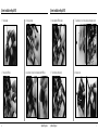
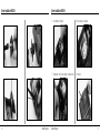
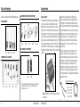
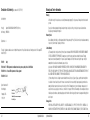
Flugmodul System
für Multiplex Royal EVO und Multiplex 3030
Inhaltsverzeichnis
Einleitung....................................................................................................3
Funktionen und Vorteile..............................................................................4
Spezifikationen............................................................................................4
DSM Flugmodule...............................................................................4
Wichtige Modul Informationen....................................................................5
SYSTEM INSTALLATION (Royal EVO)........................................................6
SYSTEM INSTALLATION (MC3030)...........................................................8
Empfängereinbau......................................................................................12
AR12000 Einbau..............................................................................13
Bindung....................................................................................................15
Bindungsverfahren...........................................................................15
Fail Safe Funktionen.................................................................................18
SmartSafe........................................................................................18
Empfängerfunktion...........................................................................18
Nach dem Anschließen....................................................................18
Voreinstellung Fail Safe............................................................................19
Empfängerfunktion...........................................................................19
Nach dem Anschließen....................................................................19
Programmierung SmartSafe (alle SPM Empfänger).........................19
Programmierung Voreingestelltes Fail Safe (AR12000/12100)........19
Einleitung
Besonderheiten ........................................................................................20
Reichweitentest Modulsysteme.................................................................21
Durchführung des Reichweitentests.................................................21
Flight Log – optional für den AR12000....................................................22
Einsatz des Flight Logs....................................................................22
EU-Konformitätserklärung.........................................................................23
Garantie und Service Informationen..........................................................24
Warnhinweise...................................................................................24
Garantiezeitraum .............................................................................24
Beschränkte Haftung........................................................................24
Schadeneinschränkungen................................................................25
Sicherheitshinweise.........................................................................25
Fragen, Service................................................................................25
Überprüfung und Reparatur ............................................................25
Garantiereparatur.............................................................................26
Kostenpflichtige Reparatur ..............................................................26
Kontaktinformationen.......................................................................26
Sicherheitshinweise ........................................................................27
Spektrum Flugmodul Systeme bieten einen überragende Übertragungstrecke zu Ihrem Flugmodell. Sie brauchen nicht länger auf eine freie Frequenz warten oder sich
Sorgen um Störungen durch schlechte Elektromotoren, Zündsystemen oder HF Störungen zu machen. Die Spektrum Modulsysteme basieren auf der originären DSM2
Technologie, der 2. Generation der Digitalen Spread Spektrum Modulation und bieten eine störungsfreie Verbindung zu dem Modell.
Das Modul arbeitet auf der Frequenz von 2,4GHz, dem weltweit eingesetzten ISM Frequenzband. Jedes Modul ist mit dem GUID, einem eindeutigen seriellen Digital Code
versehen. Wenn ein Empfänger programmiert wird (mit dem Bindungsprozess), speichert er diesen Code und verarbeitet nur die Signale, die mit diesem Code markiert
sind. Alle anderen Signale werden ignoriert.
Spektrum Flugmodule sind kompatibel mit allen Spektrum DSM2 Flugempfängern (nicht mit dem AR6000) und allen DSM2 2,4GHz Empfängern von JR.
Hinweis: Module sind nicht mit dem AR6000 Empfänger kompatibel.
Wichtig: Wenn Sie das Modul mit den Empfängern AR6100 oder AR6300 fliegen ergibt es sich aus der Natur der Sache, dass dieser Empfänger nur in
Parkfliegern eingesetzt werden dürfen. Dies schließt alle Typen von kleinen Elektroseglern und Hubschraubern ein. Fliegen Sie auf keinen Fall Modelle mit einem
Verbrennungsmotor oder große Elektroflugzeuge mit dem AR6100 oder AR6300, da ein Signal- und damit Kontrollverlust sehr wahrscheinlich ist.
Horizon Hobby ist nicht der Hersteller und auch nicht der Vertriebspartner für Multiplex
Fernsteueranlagen. Wir haben das Produkt als Zubehör im Rahmen eines Zusatzmoduls
entwickelt und in der Einsatzumgebung der Multiplex auf Kompatibilität getestet.
Die Marke Spektrum wird mit Genehmigung von Bachmann Industries. verwendet.
2
Spektrum Flugmodul
Spektrum Flugmodul
3
Funktionen und Vorteile
Wichtige Modulinformationen
•
•
•
•
•
•
•
•
Stellen Sie unbedingt sicher, dass der Sender auf PPM programmiert ist. Ziehen Sie die Anleitung Ihrer Anlage heran, um dies einzustellen. Hinweis: Spektrum
Module arbeiten nicht im PCM Mode oder einem anderen PPM Mode.
•
Schalten Sie niemals das Modul ohne Antenne ein. Dadurch wird die Elektronik überlastet, was zu dauerhaften Schäden führt.
•
Vor dem ersten Einsatz muss der Empfänger gebunden werden (siehe Seite 15 dieser Anleitung). Im Bindungsprozess wird der unverwechselbare Digitalcode (GUID)
im Empfänger gespeichert. In diesem Prozess werden auch die Failsafe Daten gespeichert. Es wird empfohlen, dass System nach der Programmierung der Anlage
nochmals zu binden, um sicherzustellen, dass die richtigen Failsafe Positionen vorhanden bleiben.
•
Vor jedem Einsatz sollte die Reichweite getestet werden (sieh Seite 21), um sicherzustellen, dass das System korrekt arbeitet.
•
Wenn Sie das Modul mit den Empfängern AR6100 oder AR6300 fliegen ergibt es sich aus der Natur der Sache, dass dieser Empfänger nur in Parkfliegern eingesetzt
werden dürfen. Dies schließt alle Typen von kleinen Elektroseglern und Hubschraubern ein. Fliegen Sie auf keinen Fall Modelle mit einem Verbrennungsmotor oder
große Elektroflugzeuge mit dem AR6100 oder AR6300, da ein Signal- und damit Kontrollverlust sehr wahrscheinlich ist.
•
Das Modul enthält die DSM2 Technologie und ist kompatibel zu allen DSM2 Empfängern. Damit kann das Modul mit dem DSM1 Empfänger AR6000 nicht betrieben
werden.
Nutzt das 2,4GHz Band und ist international einzusetzen
Kein Warten auf eine freie Frequenz
Keine Störung durch Kanaldoppelbelegungen
Völlige Sicherheit gegen fremde HF Quellen wie Mobiltelefone, WIFI oder andere Übertragungssysteme
Immun gegen alle Störquellen im Modell (E-Motoren, Metallgetriebe, Zündsysteme)
Wartungsfrei
Fail Safe System für den Gaskanal (siehe Seite 18)
Spezifikation
DSM Flugmodule
Frequenz - 2400–2483MHz
Spektrale Kapazität - 40 Anlagen
Modulation - Direct Sequence Spread Spektrum
DSSS Kodierungsverstärkung - 18dB
Diversity - Patentierta MultiLink: Weg, Zeit und Frequenz
Strom Modul - 200mA
Strom Empfänger - 70mA
Empfängerspannung - 3.5-9V
Servokanäle - 9
Auflösung - 1024 mit 4x Oversampling
4
Spektrum Flugmodul
Spektrum Flugmodul
5
System Installation–Royal EVO
System Installation–Royal EVO
1.
Remove backplate.
3.
Remove legacy antenna.
5.
Install new Spektrum RF Module board.
7.
Feed antenna wire. Connect to module, taking care not to damage connector.
2.
Remove existing RF module.
4.
Apply hook and loop to back of main board and Spektrum RF Module.
6.
Plug in wire harness noting polarity.
8.
Replace back cover.
6
Spektrum Flugmodul
Spektrum Flugmodul
7
System Installation–MC3030
System Installation–MC3030
1.
Remove backplate.
3.
Drill 5.00 mm hole
5.
2.
Remove existing RF module.
4.
Apply hook and loop fastener to new Spektrum RF Module and install.
8
Spektrum Flugmodul
After removing legacy antenna, replace with 2.4GHz antenna.
Spektrum Flugmodul
9
System Installation–MC3030
System Installation–MC3030
6.
Connect wire harness noting polarity.
8.
Ensure all wires are connected properly.
7.
Feed antenna wire. Connect to module, taking care not to damage connector.
9.
Replace back.
10
Spektrum Flugmodul
Spektrum Flugmodul
11
Einbau des Empfängers
Empfängereinbau
Das Module ist mit allen Spektrum DSM2 and JR/DSM Empfängern kompatibel
DSM2 EMPFÄNGER MIT VOLLER REICHWEITE UND POWERSAFE
Einbau des AR12000
PARKFLIEGEREMPFÄNGER
• AR7100*
• AR7100R*
• AR9100*
• AR12000*
• AR12100*
DSM 2 EMPFÄNGER FÜR KOHLEFASERRÜMPFE
• AR6110
• AR6110E
• AR6300
• AR6400
Der AR12000 besitzt zine interne Empfänger und drei externe Empfänger. Damit
bietet er einen ausgezeichneten Schutz der HF Verbindung durch optimale
Mehrwegtechnologie. Ein interner Empfänger befindet sich auf der Platine. Zwei
weitere Satelliten müssen mit dem Empfänger verbunden sein, damit das System
arbeitet. Empfänger muss in einen der Ports am Gehäuse gesteckt werden, damit er
arbeitet. Zusätzlich kann ein weiterer externer Empfänger an den verbleibenden Port
angesteckt werden, so das maximal 4 Empfänger betrieben werden können. Durch
die Platzierung dieser Empfänger an verschiedenen Orten im Modell befindet sich
jeder der Empfänger in seiner eignen HF Umgebung, was zu einer herausragenden
Wegdiversity führt (die Fähigkeit des Empfängers, das Signal aus allen Richtungen
zu empfangen).
DSM2 EMPFÄNGER MIT VOLLER REICHWEITE
• AR9300*
•AR500
• AR6200
• AR7000*
• AR7600*
• AR9000*
• AR6250
Spektrum Flugmodul
Die externen Empfänger werden an untersschiedlichen Stellen eingebaut, um die
Weg Diversity zu optimieren. Jeder so abgesetzte Empfänger sieht seine eigene
HF Umgebung und ist der Schlüssel zu der überragenden Sicherheit dieser
HF Verbindung. Dies gilt auch für Modelle mit vielen induktiven Materialien,
wie Gastrubinen, Schubrohre, Carbon, Resorohre und ähnliches, die Signale
beeinflussen können.
Verwenden Sie Doppelklebeband, um die externen Empfänger zu montieren.
Die Antennen sollten dabei einen Abstand von mindestens 51mm von den
Antennen des Hauptempfängers haben. Ideal ist zudem der Einbau in der Form,
dass die Antenne des externen Empfängers rechtwinklig zu den Hauptantennen
ist. Wir haben herausgefunden, dass dies nicht unbedingt erforderlich ist.
Verbindungskabel mit verschiedenen Längen sind erhältlich. In anspruchsvollen
Flugzeugen hat sich die Platzierung der externen Empfängern an verschiedenen
Orten des Modells bewährt. Dabei sollte der Abstand zu konduktiven Materialien so
groß wie praktisch möglich sein.
Verlängerungskabel für externe Empfänger
*Das optionale Flight Log (SPM9540) ist für diese Empfänger für die Aufzeichnung von Daten verfügbar.
Sie können Daten zur HF Verbindung anzeigen lassen und so den Einbau des Empfangssystems
optimieren. Details finden Sie ab Seite 21.
Hinweis: Der AR12000 kann nur mit mindestens zwei externen Empfänger
betrieben werden.
12
Wenden Sie beim Einbau des Empfängers die gleiche Methode an, wie bei
einem konventionellen Empfänger. Wickeln Sie den Empfänger in Schaumstoff
ein und befestigen Sie ihn mit Gummibändern oder Klettband. Bei Elektro oder
Turbinenmodellen kann der Empfänger auch mit Doppelklebeband befestigt werden.
Spektrum Flugmodul
6-inch (152mm)
9-inch (228mm)
12-inch (305mm)
24-inch (610mm)
SPM9010
SPM9011
SPM9012
SPM9013
36-inch (914mm) SPM9014
13
Empfängereinbau
Binden
Dies ist eine typische Installation mit dem Empfänger an konventioneller Stelle und
die externen Empfänger in der Spitze und im Leitwerk.
Es ist erforderlich, das Modul mit dem Empfänger zu binden, so dass der
Empfänger nur die Signale dieses spezifischen Empfängers verarbeitet. Ohne
Bindung arbeitet das System nicht. Außerdem werden beim Binden die Fail Safe
Positionen abgespeichert.
1.
Bauen Sie das Empfänger System so auf und stecken Sie den
Bindungsstecker in die Ladebuchse des Schalterkabels.
Die folgenden Instruktionen beziehen sich auf einen AR12000 Empfänger, sind aber
sinngemäß auch auf die anderen Empfänger anzuwenden.
Bindungsverfahren
Der AR12000 empfänger muss mit dem Modul gebunden werden. Hier wird der
spezifische serielle Digitalcode des Senders übermittelt. Nach dem Binden wird der
Empfänger nur mit diesem Modul funktionieren bis er neu gebunden wird.
Hinweis: Das Binden mit einem Schalterkabel kann nur mit dreiadrigen
Kabeln, wie bei SPM9530, durchgeführt werden.
Hinweis: Um ein System mit einem Regler mit BEC zu binden, stecken Sie
bitte den Bindungsstecker in den Batterieport des Empfängers.
14
Spektrum Flugmodul
Spektrum Flugmodul
15
Binden
2.
16
Schalten Sie den Empfänger ein. Hinweis: Die LED beider Empfänger müssen
hochfrequent blinken und zeigen so an, dass sie zum Binden bereit sind.
Binden
3.
Nehmen Sie die gewünschte Failsafe Position am Sender ein, normalerweise
Gas auf Neutral und die andere Kanäle neutral.
Spektrum Flugmodul
4.
Drücken und halten Sie den Bindungsknopf am Modul während Sie den
Sender einschalten. Der Bindungsknopf blinkt und die Bindung erfolgt
innerhalb der nächsten Sekunden. Das System ist fertig gebunden, wenn die
LED an den Empfängern dauerhaft blinken. Hinweis.
Spektrum Flugmodul
5.
6.
Ziehen Sie den Bindungsstecker ab und bewahren Sie ihn gut auf.
Nach der Programmierung des Senders ist es wichtig, Ihr System noch
einmal zu binden, damit die tatsächlichen Knüppelstellungen für die Fail Safe
Funktion übertragen werden können.
17
Fail Safe Funktion
Alle Spektrum Empfänger verfügen über das SmartSafe System während der
AR12000 über zwei Systeme verfügt, SmartSafe und Voreingestelltes Fail Safe.
SmartSafe
Dieser Fail Safe Typ wird für alle Elektromodelle und in den meisten Fällen auch für
Verbrenner Modelle und Hubschrauber empfohlen.
SmartSafe funktioniert so:
Voreingestelltes Failsafe
Nach dem Anschließen
Schaltet man den Sender ein und verbindet sich dieser mit dem Empfänger
können alle Kanäle normal betrieben werden. Nach der Verbindung und bei einem
Signalverlust fährt SmartSafe nur das Gas Servo in die vorgesehene Fail Safe
Position. Alle anderen Kanäle werden eingefroren. Wird die Verbindung wieder
hergestellt, übernimmt das System sofort wieder die Kontrolle (weniger als 4ms).
Empfängerfunktion
Wenn nur der Empfänger eingeschaltet ist (Sendersignal liegt nicht vor), fahren alle
Servos in der Regel auf neutral und das Fahrwerk wird ausgefahren, bis auf das
Gas. Diese Positionen werden beim Binden im Empfänger gespeichert. Zu diesem
Zeitpunkt gibt es kein Ausgangssignal am Gas, um das armieren eines Reglers zu
verhindern. Bei Verbrennermodellen bekommt das Gasservo kein Signal und bleibt
in der vorhandenen Stellung.
18
Voreingestelltes Failsafe ist ideal für Segler Piloten und für einige Piloten mit
Verbrenner Modellen.
Programmierung SmartSafe
(alle Spektrum Empfänger)
Empfängerfunktion
Der Bind Stecker verbleibt während des gesamten Bindungsprozess (Seite 14) im
Empfänger. Er wird erst entfernt, wenn der Empfänger mit dem Sender verbunden
ist, was durch Anlaufen aller Servos bestätigt wird. SmartSafe ist programmiert.
Wenn nur der Empfänger eingeschaltet ist (Sendersignal liegt nicht vor), fahren alle
Servos in der Regel auf neutral und das Fahrwerk wird ausgefahren, bis auf das
Gas. Diese Positionen werden beim Binden im Empfänger gespeichert. Zu diesem
Zeitpunkt gibt es kein Ausgangssignal am Gas, um das armieren eines Reglers zu
verhindern. Bei Verbrennermodellen bekommt das Gasservo kein Signal und bleibt
in der vorhandenen Stellung.
Verbindung
Wenn der Sender nach dem Einschalten sich mit dem Empfänger verbindet,
funktionieren alle Servos normal. Geht das Signal verloren, werden alle Servos in
die vorgesehene Fail Safe Position gefahren. Für Segler wird empfohlen, Klappen
und Spoiler auszufahren, um ein Davonfliegen zu verhindern. Einige Piloten
möchten eine leichte Kurve mit Schleppgas für das Fail Safe programmieren. Ist
das Signal zurück, übernimmt das System sofort die Kontrolle (weniger als 4ms).
Spektrum Flugmodul
Spektrum Flugmodul
Programmierung Failsafe voreingestellt
(nur AR12000 und AR12100)
Für den Bindungsprozess wird der Bind Stecker in die Ladebuchse des
Schalterkabels oder den Batterieport des Empfängers gesteckt. Wird Strom
eingeschaltet, blinken die LED an den Empfängern. Bevor Sie nun den Empfänger
binden, ziehen Sie den Bind Stecker aus dem Empfänger wieder ab. Die LED
blinken immer noch. Bringen Sie die Knüppel und Schalter in die gewünschte Fail
Safe Position und schalten Sie den Sender mit gedrücktem Bindungsstecker ein.
Innerhalb der nächsten 15 Sekunden wird die Bindung hergestellt. Der Empfänger
ist auf voreingestelltes Fail Safe programmiert.
Hinweis. Die Failsafe Positionen werden über die Knüppel und
Schalterstellung am Sender definiert.
19
Modul Sonderhinweis
Reichweitentest des Spektrum Moduls
Bevor Ihren neuen Modul übertragen kann, muss der Sender in PPM24 programmiert
sein. Dies wird über das Menü Modulation eingestellt, welches Sie in der Anleitung
der MC-24 beschrieben finden.
Vor jedem Einsatz insbesondere mit einem neuen Modell, ist es wichtig, die
Reichweite zu testen. Dieser Test wird mit dem Bindungsknopf am Modul
durchgeführt. Durch Drücken des Knopfes wird die Sendeleistung reduziert, um den
Test durchzuführen.
Binden Sie jetzt den Empfänger (siehe Seite 15). Ihr System ist nun einsatzbereit.
Reichweitentest des Moduls
1.
2.
Stellen Sie das Modell an den Boden und entfernen Sie sich 30 Schritte (28 m).
Wenden Sie sich dem Modell so zu, als würden Sie fliegen und drücken Sie
den Bindungsknopf.
3. Sie sollten volle Kontrolle über das Modell haben.
4. Wenn Sie Probleme haben, wenden Sie sich an den Horizon Produkt Service:
European Union: +49 4121 46199 66 (Deutschland)
+44 1279 641 097 (United Kingdom)
United States: 1-877-504-0233
20
Spektrum Flugmodul
Spektrum Flugmodul
30 30
paces
(28 (90
m) ft/28 m)
Schritte
Drücken
und halten
Sie button
Press
and hold
the bind
den Bindungsknopf
21
Flight Log – optional für den AR12000
EU-Konformitätserklärung
Konformitätserklärung gemäß Gesetz über Funkanlagen und Telekomunikationseinrichtungen (FTEG) und der Richtlinie 1999/5/EG (R&TTE)
Das Flight Log (SPM9540) mit Spektrum ist mit den Empfängern AR7000, AR7100,
AR7100R, AR9000, AR9100, AR12000 und AR12100 kompatibel. Das Flight Log
gibt Auskunft über die Güte des HF Links, den Empfang an den Antennen und die
Daten der externen Empfänger. Zusätzlich wird die Empfängerspannung angezeigt.
Drücken Sie den Knopf für die folgenden Informationen:
Declaration of conformity in accordance with the Radio and Telecommunications Terminal Equipment Act (FETG) and directive 1999/5/EG (R&TTE)
A - Antennen Ausblendung Antenne A
Horizon Hobby Deutschland GmbH
Hamburger Str. 10
25335 Elmshorn
B - Antennen Ausblendung Antenne B
L - Antennen Ausblendung linke externe Antenne
R - Ausblendung rechte externe Antenne
F - Frame Verlust
H - Hold
Antennen Ausblendung gibt den Verlust eines Bits an Information an der
entsprechenden Antenne an. Es ist normal 50-100 Ausblendungen pro Antennen
während eines Fluges zu haben. Wenn eine Antennen über 500 Ausblendungen im
Flug aufweist, sollte die Antennen neu positioniert werden.
Frame Verlust ist die gleichzeitige Ausblendung aller Antennen zur gleichen
Zeit. Der HF Link arbeitet optimal, wenn weniger als 20 Frame Verluste pro Flug
auftreten.
Einsatz des Flight Logs
Stecken Sie das Flight Log in den Daten Port des Empfängers, bevor Sie
diesen oder den Sender ausschalten. Das Display zeigt automatisch die
Empfängerspannung i.e 6V2=6.2Volt.
22
Ein Hold stellt sich ein, wenn 45 Frames hintereinander verloren gehen. Wird
ein Hold angezeigt, muss das gesamte System sorgfältig geprüft werden. Dabei
müssen die Antennenpositionen genauso überprüft werden, wie der Sender und
Empfänger selbst.
Hinweis: Sie können eine Servoverlängerung verwenden, um das Flight
Log einzusetzen, ohne die Kabinenhaube öffnen zu müssen. In Modellen,
in denen ausreichend Platz vorhanden ist, können Sie das Flight Log auch
fest mit Doppelklebeband einbauen. Bei Hubschraubern erfolgt dies zum
Beispiel am Hauptchassis.
Spektrum Flugmodul
erklärt das Produkt: declares the product:
Geräteklasse: 2
equipment class 2
Spektrum DSM2 Modulsystem mit AR12000 Empfänger EVO/3030-Comp (SPMMS3132)
Spektrum DSM2 AIRMOD with AR12000 EVO/3030-Comp (SPMMS3132)
den grundlegenden Anforderungen des § 3 und den übrigen einschlägigen Bestimmungen des FTEG (Artikel 3 der R&TTE) entspricht. complies with the essential requirments of § 3 and other relevant provisions of the
FTEG (Article 3 of the R&TTE directive).
Angewendete harmonisierte Normen:
Harmonised standards applied:
EN 301 489-1 V1.6.1 (2005-09)
Schutzanforderungen in Bezug auf elektromagnetische
EN 301 489-17 V1.2.1 (2002-08)
Verträglichkeit § 3 (1) 2, (Artikel 3 (1) b))
Protection requirement concerning electromagnetic compatibility § 3 (1) 2, (article 3 (1)b))
EN 300 328 V1.7.1 (2004-11)
Maßnahmen zur effizienten Nutzung des Frequenzspektrums § 3 (2)(Artikel 3 (2))
Measures for the efficient use of the radio frequency spectrum § 3 (2) (Article 3 (2))
Elmshorn, 09.10.2008
Spektrum Flugmodul
Jörg Schamuhn, Geschäftsführer
Managing Director
23
Garantie und Service Informationen
Schadensbeschränkung
Warnung
Ein ferngesteuertes Modell ist kein Spielzeug. Es kann, wenn es falsch eingesetzt wird, zu erheblichen Verletzungen bei Lebewesen und Beschädigungen an
Sachgütern führen. Betreiben Sie Ihr RC-Modell nur auf freien Plätzen und beachten Sie alle Hinweise der Bedienungsanleitung des Modells wie auch der
Fernsteuerung.
Garantiezeitraum
Exklusive Garantie – Horizon Hobby Inc (Horizon) garantiert, dass das gekaufte Produkt (Produkt) frei von Material- und Montagefehlern ist. Der Garantiezeitraum
entspricht den gesetzlichen Bestimmung des Landes, in dem das Produkt erworben wurde. In Deutschland beträgt der Garantiezeitraum 6 Monate und der
Gewährleistungszeitraum 18 Monate nach dem Garantiezeitraum.
Einschränkungen der Garantie
(a) Die Garantie wird nur dem Erstkäufer (Käufer) gewährt und kann nicht übertragen werden. Der Anspruch des Käufers besteht in der Reparatur oder dem Tausch
im Rahmen dieser Garantie. Die Garantie erstreckt sich ausschließlich auf Produkte, die bei einem autorisierten Horizon Händler erworben wurden. Verkäufe an
dritte werden von dieser Garantie nicht gedeckt. Garantieansprüche werden nur angenommen, wenn ein gültiger Kaufnachweis erbracht wird. Horizon behält sich
das Recht vor, diese Garantiebestimmungen ohne Ankündigung zu ändern oder modifizieren und widerruft dann bestehende Garantiebestimmungen.
(b) Horizon übernimmt keine Garantie für die Verkaufbarkeit des Produktes, die Fähigkeiten und die Fitness des Verbrauchers für einen bestimmten Einsatzzweck
des Produktes. Der Käufer allein ist dafür verantwortlich, zu prüfen, ob das Produkt seinen Fähigkeiten und dem vorgesehenen Einsatzzweck entspricht.
(c) Ansprüche des Käufers – Es liegt ausschließlich im Ermessen von Horizon, ob das Produkt, bei dem ein Garantiefall festgestellt wurde, repariert oder
ausgetauscht wird. Dies sind die exklusiven Ansprüche des Käufers, wenn ein Defekt festgestellt wird.
Horizon behält sich vor, alle eingesetzten Komponenten zu prüfen, die in den Garantiefall einbezogen werden können. Die Entscheidung zur Reparatur oder zum
Austausch liegt nur bei Horizon. Die Garantie schließt kosmetische Defekte oder Defekte, hervorgerufen durch höhere Gewalt, falsche Behandlung des Produktes,
falscher Einsatz des Produktes, kommerziellen Einsatz oder Modifikationen irgendwelcher Art aus.
Die Garantie deckt Schäden, die durch falschen Einbau, falsche Handhabung, Unfälle, Betrieb, Service oder Reparaturversuche, die nicht von Horizon ausgeführt
wurden, aus. Rücksendungen durch den Käufer direkt an Horizon oder eine seiner Landesvertretung bedürfen der schriftlichen.
24
Spektrum Flugmodul
Horizon ist nicht für direkte oder indirekte Folgeschäden, Einkommensausfälle oder kommerzielle Verluste, die in irgendeinem Zusammenhang mit dem Produkt
stehen nicht verantwortlich, unabhängig ab ein Anspruch im Zusammenhang mit einem Vertrag, der Garantie oder der Gewährleistung erhoben werden. Horizon
wird darüber hinaus keine Ansprüche aus einem Garantiefall akzeptieren, die über den individuellen Wert des Produktes hinaus gehen. Horizon hat keine Einfluss
auf den Einbau, die Verwendung oder die Wartung des Produktes oder etwaiger Produktkombinationen, die vom Käufer gewählt werden. Horizon übernimmt keine
Garantie und akzeptiert keine Ansprüche für in der folge auftretende Verletzungen oder Beschädigungen. Mit der Verwendung und dem Einbau des Produktes
akzeptiert der Käufer alle aufgeführten Garantiebestimmungen ohne Einschränkungen und Vorbehalte.
Wenn Sie als Käufer nicht bereit sind, diese Bestimmungen im Zusammenhang mit der Benutzung des Produktes zu akzeptieren, werden Sie gebeten, dass
Produkt in unbenutztem Zustand in der Originalverpackung vollständig bei dem Verkäufer zurückzugeben.
Sicherheitshinweise
Dieses ist ein hochwertiges Hobby Produkt und kein Spielzeug. Es muss mit Vorsicht und Umsicht eingesetzt werden und erfordert einige mechanische wie auch
mentale Fähigkeiten. Ein Versagen, das Produkt sicher und umsichtig zu betreiben kann zu Verletzungen von Lebewesen und Sachbeschädigungen erheblichen
Ausmaßes führen. Dieses Produkt ist nicht für den Gebrauch durch Kinder ohne die Aufsicht eines Erziehungsberechtigten vorgesehen. Die Anleitung enthält
Sicherheitshinweise und Vorschriften sowie Hinweise für die Wartung und den Betrieb des Produktes. Es ist unabdingbar, diese Hinweise vor der ersten
Inbetriebnahme zu lesen und zu verstehen. Nur so kann der falsche Umgang verhindert und Unfälle mit Verletzungen und Beschädigungen vermieden werden.
Fragen, Hilfe und Reparaturen
Ihr lokaler Fachhändler und die Verkaufstelle können eine Garantiebeurteilung ohne Rücksprache mit Horizon nicht durchführen. Dies gilt auch für
Garantiereparaturen. Deshalb kontaktieren Sie in einem solchen Fall den Händler, der sich mit Horizon kurz schließen wird, um eine sachgerechte Entscheidung zu
fällen, die Ihnen schnellst möglich hilft.
Wartung und Reparatur
Muss Ihr Produkt gewartet oder repariert werden, wenden Sie sich entweder an Ihren Fachhändler oder direkt an Horizon. Packen Sie das Produkt sorgfältig ein.
Beachten Sie, dass der Originalkarton in der Regel nicht ausreicht, um beim Versand nicht beschädigt zu werden. Verwenden Sie einen Paketdienstleister mit einer
Tracking Funktion und Versicherung, da Horizon bis zur Annahme keine Verantwortung für den Versand des Produktes übernimmt.
Bitte legen Sie dem Produkt einen Kaufbeleg bei, sowie eine ausführliche Fehlerbeschreibung und eine Liste aller eingesendeten Einzelkomponenten. Weiterhin
benötigen wir die vollständige Adresse, eine Telefonnummer für Rückfragen, sowie eine Email Adresse.
Spektrum Flugmodul
25
Sicherheit und Warnungen
Garantie und Reparaturen
Garantieanfragen werden nur bearbeitet, wenn ein Originalkaufbeleg von einem autorisierten Fachhändler beiliegt, aus dem der Käufer und das Kaufdatum
hervorgeht. Sollte sich ein Garantiefall bestätigen wird das Produkt repariert oder ersetzt. Diese Entscheidung obliegt einzig Horizon Hobby.
Kostenpflichtige Reparaturen
Liegt eine kostenpflichtige Reparatur vor, erstellen wir einen Kostenvoranschlag, den wir Ihrem Händler übermitteln. Die Reparatur wird erst vorgenommen, wenn
wir die Freigabe des Händlers erhalten. Der Preis für die Reparatur ist bei Ihrem Händler zu entrichten. Bei kostenpflichtigen Reparaturen werden mindestens 30
Minuten Werkstattzeit und die Rückversandkosten in Rechnung gestellt. Sollten wir nach 90 Tagen keine Einverständniserklärung zur Reparatur vorliegen haben,
behalten wir uns vor, das Produkt zu vernichten oder anderweitig zu verwerten.
Achtung: Kostenpflichtige Reparaturen nehmen wir nur für Elektronik und Motoren vor. Mechanische Reparaturen, besonders bei
Hubschraubern und RC-Cars sind extrem aufwendig und müssen deshalb vom Käufer selbst vorgenommen werden.
•
•
•
•
•
•
•
Als Anwender des Produktes sind Sie verantwortlich für den sicheren Betrieb aus dem eine Gefährdung für Leib und Leben sowie Sachgüter nicht hervorgehen soll.
Befolgen Sie sorgfältig alle Hinweise und Warnungen für dieses Produkt und für alle Komponenten und Produkte, die Sie im Zusammenhang mit diesem Produkt einsetzen.
Ihr Modell empfängt Funksignale und wird dadurch gesteuert. Funksignale können gestört werden, was zu einem Signalverlust im Modell führen würde. Stellen Sie
deshalb sicher, dass Sie um Ihr Modell einen ausreichenden Sicherheitsabstand einhalten, um einem solchen Vorfall vorzubeugen.
Betreiben Sie Ihr Modell auf einem offenen Platz, weit ab von Verkehr, Menschen und Fahrzeugen.
Betreiben Sie Ihr Fahrzeug nicht auf einer öffentlichen Straße.
Betreiben Sie Ihr Modell nicht in einer belebten Straße oder einem Platz.
Betreiben Sie Ihren Sender nicht mit leeren Batterien oder Akkus.
Folgen Sie dieser Bedienungsanleitung mit allen Warnhinweisen sowie den Bedienungsanleitungen aller Zubehörteile, die Sie einsetzen.
Halten Sie Chemikalien, Kleinteile und elektrische Komponenten aus der Reichweite von Kindern.
Feuchtigkeit beschädigt die Elektronik. Vermeiden Sie das Eindringen von Wasser, da diese Komponenten dafür nicht ausgelegt sind.
Entsorgung in der Europäischen Union
Europäische Union:
Elektronik und Motoren müssen regelmäßig geprüft und gewartet werden. Für Servicezwecke sollten die Produkt an die folgende Adresse gesendet werden:
Hamburger Str. 10
25335 Elmshorn
Germany
Bitte rufen Sie +49 4121 4619966 an oder schreiben Sie uns ein Email an [email protected] um jede mögliche Frage zum Produkt oder der
Garantieabwicklung zu stellen.
Dieses Produkt darf nicht über den Hausmüll entsorgt werden. Es ist die Verantwortung des Benutzers, dass Produkt an einer registrierten Sammelstelle für Elektroschrott
abzugeben diese Verfahren stellt sicher, dass die Umwelt geschont wird und natürliche Ressourcen nicht über die Gebühr beansprucht werden. Dadurch wird das
Wohlergehen der menschlichen Gemeinschaft geschützt. Für weitere Informationen, wo der Elektromüll entsorgt werden kann, können Sie Ihr Stadtbüro oder Ihren lokalen
Entsorger kontaktieren.
UK
FI
CZ
AT
NL
DE
EE
SK
IT
LU
DK
LV
HU
ES
MT
BG
LT
RO
PT
CY
SE
PL
SI
IE
GR
Gedruckt 09/09
26
Spektrum Flugmodul
Spektrum Flugmodul
15753
27
© 2009 Horizon Hobby, Inc.
4105 Fieldstone Road
Champaign, Illinois 61822 USA
(877) 504-0233
www.horizonhobby.com
www.spektrumrc.com
Horizon Hobby UK, LTD.
Units 1-4 Ployters Rd.
Staple Tye
Harlow, Essex CM18 7NS
United Kingdom
+44 (0)1279 641 097
www.horizonhobby.co.uk
Horizon Hobby Deutschland GmbH
Hamburger Str. 10
25335 Elmshorn
Germany
+49 4121 46199 60
www.horizonhobby.de
Air Module System
for Multiplex Royal EVO and Multiplex 3030
Table of Contents
Introduction....................................................................................................... 3
Features and Benefits......................................................................................... 4
Specifications.................................................................................................... 4
DSM Air Modules..................................................................................... 4
Important Module Information........................................................................... 5
System Installation (Royal EVO)........................................................................ 6
System Installation (MC3030)........................................................................... 8
Installing the Receiver.......................................................................................12
Installing the AR12000.............................................................................13
Binding.............................................................................................................15
How to Bind.............................................................................................15
Failsafe Functions.............................................................................................18
SmartSafe................................................................................................18
Receiver Power Only................................................................................18
After Connection......................................................................................18
Preset Failsafe...................................................................................................19
Receiver Power Only................................................................................19
After Connection......................................................................................19
Programming SmartSafe (All Spektrum Aircraft Receivers).....................19
Programming Preset Failsafe (AR12000/12100 Spektrum Receivers).....19
Introduction
Module Special Instructions.............................................................................20
How to Range Test the Spektrum Module System............................................ 21
Range Testing the Module System.......................................................... 21
Flight Log—Optional for the AR12000............................................................ 22
Using the Flight Log............................................................................... 22
FCC Information.............................................................................................. 23
Compliance Information for European Union....................................................23
Declaration of Conformity.................................................................................24
Warranty and Service Information.................................................................... 25
Warning.................................................................................................. 25
Warranty Period...................................................................................... 25
Limited Warranty..................................................................................... 25
Damage Limits........................................................................................ 25
Safety Precautions.................................................................................. 26
Questions, Assistance, and Repairs........................................................ 26
Inspection or Repairs.............................................................................. 26
Warranty Inspection and Repairs............................................................ 26
Non-Warranty Repairs............................................................................. 27
Contact Information................................................................................ 27
Safety, Precautions, and Warnings.......................................................... 28
Spektrum’s Aircraft Module systems offer the ultimate in radio link security. No longer will you have to wait for an open frequency, or struggle with interference caused from
noisy motors, ignition systems or other RF noise-generating sources. Spektrum’s module systems utilize proprietary DSM2™ second generation Digital Spread Spectrum
Modulation technology, providing an impenetrable radio link.
Operating within the ultra high frequency 2.4GHz worldwide ISM band, each module is programmed with its own unique serial code called GUID (Globally Unique
Identification code). Once a receiver is programmed to a specific module (called binding), the receiver will only recognize and respond to that module ignoring signals
from any other sources.
Spektrum’s module systems are compatible with all Spektrum™ DSM2™ and JR™/DSM® receivers (which excludes AR6000).
Note: The Module system is not compatible with the AR6000 first generation DSM receivers.
Important: When using the Module system with the Spektrum parkflyer receivers, it’s imperative that this receiver only be flown in parkflyer-type models. This
includes all types of small electric airplanes and mini and micro helicopters. Do not fly the parkflyer receiver in large gas, glow or large electric aircraft as loss of
control at extended range due to signal blocking issues can occur.
US patent 7,391,320. Other patents pending.
Horizon Hobby is neither producer of nor distribution partner for Multiplex radios. We have
independently developed our product as an add-on to the Multiplex radios and have tested its
compatibility with the Multiplex radios.
The Spektrum trademark is used with permission of Bachmann Industries, Inc.
2
Spektrum Air Module
Spektrum Air Module
3
Features and Benefits
Important Module Information
•
•
•
•
•
•
•
•
Be sure the transmitter is in PPM mode. If necessary, refer to the instructions included with your radio system for details on how to program your transmitter to PPM
Note: The Spektrum module system will not operate in PCM mode.
•
Never power up the module unless the antenna is connected. Doing so can overload the module’s electronics causing damage to the module.
•
Before operating, the receiver must be bound to the module (see page 15 for binding instructions). Binding is the process of teaching the receiver the transmitter’s
specific GUID (globally unique identifier) code. Binding also sets the failsafe positions. It’s also recommended that the system be rebound again after radio setup to
establish and confirm the desired failsafe positions.
•
Before each flying session, it’s imperative that you do a range check (see page 21 for details) to confirm that the system is working properly.
•
When using the Module system with the parkflyer receiver, it’s imperative that this receiver only be flown in parkflyer-type models. This includes all types of small
electric airplane and mini and micro helicopters. DO NOT fly the parkflyer receiver in large gas, glow or large electric aircraft as loss of control at extended range due
to signal blocking issues can occur.
•
The Module system features DSM2 technology and is compatible will all DSM2 compatible receivers. The Module system is not compatible with the AR6000 DSM
first generation receiver.
Operates on the 2.4GHz ISM band allowing international use
No more waiting for an open frequency
Eliminates the possibility of interference from an unintentional turn-on
Bulletproof interference rejection of all outside RF sources like cell phones, WiFi systems, other transmitters, etc.
Impervious to model-generated RF interference (like noisy electric motors, metal-to-metal noise or ignition systems)
No maintenance or tuning ever required
Failsafe system drives the throttle to preset position at loss of signal (see failsafe options on page 18)
Specifications
DSM Air Modules
Frequency - 2.400–2.483GHz
Spectral capacity - 40 Systems
Type - Direct Sequence Spread Spectrum
DSSS coding gain - 18dB
Diversity - Patented MultiLink: Path, Time and Frequency
Module current - 200mA
Servo channel resolution - 1024 with 4X oversampling
4
Spektrum Air Module
Spektrum Air Module
5
System Installation–Royal EVO
System Installation–Royal EVO
1.
Remove backplate.
3.
Remove legacy antenna.
5.
Install new Spektrum RF Module board.
7.
Feed antenna wire. Connect to module, taking care not to damage connector.
2.
Remove existing RF module.
4.
Apply hook and loop to back of main board and Spektrum RF Module.
6.
Plug in wire harness noting polarity.
8.
Replace back cover.
6
Spektrum Air Module
Spektrum Air Module
7
System Installation–MC3030
System Installation–MC3030
1.
Remove backplate.
3.
Drill 5.00 mm hole
5.
2.
Remove existing RF module.
4.
Apply hook and loop fastener to new Spektrum RF Module and install.
8
Spektrum Air Module
After removing legacy antenna, replace with 2.4GHz antenna.
Spektrum Air Module
9
System Installation–MC3030
System Installation–MC3030
6.
Connect wire harness noting polarity.
8.
Ensure all wires are connected properly.
7.
Feed antenna wire. Connect to module, taking care not to damage connector.
9.
Replace back.
10
Spektrum Air Module
Spektrum Air Module
11
Installing the Receiver
Installing the AR12000
The Module system is compatible with all Spektrum DSM2 and JR/DSM receivers.
The AR12000 incorporates one internal receiver, and three remote receivers
offering the security of four simultaneous RF links for the ultimate in multipath RF security. One internal receiver is located on the main PC board, while
a minimum of two remote receivers must be plugged into the antenna ports in
order for the system to operate. By locating these receivers in different locations
throughout the aircraft, each receiver is exposed to its own RF environment,
greatly improving path diversity (the ability of the receiver to see the signal in all
conditions).
FULL RANGE AND POWERSAFE DSM2 RECEIVERS
PARKFLYER RECEIVERS
• AR7100*
• AR7100R*
• AR9100*
• AR12000*
• AR12100*
CARBON FUSELAGE DSM2 RECEIVERS
• AR6110E
• AR6110
• AR6300
FULL RANGE DSM2 RECEIVERS
•AR500
12
• AR6200
• AR7000*
• AR7600*
• AR9000*
Mounting the remote receiver(s) in a different location(s), from the primary receiver,
gives tremendous improvements in path diversity. Essentially each receiver sees a
different RF environment and this is the key to maintaining a solid RF link, even in
aircraft that have substantial conductive materials, (e.g. turbine engines with metal
tail pipes, carbon fiber, tuned pipes, etc.) which can weaken the signal.
Using double-sided foam tape (servo tape), mount the remote receiver(s) keeping
the remote antenna(s) at least 2 inches (51mm) away from the primary antenna.
Ideally the antennas will be oriented perpendicular to each other, however, we’ve
found this to not be critical. Leads of varying length are available (see table below),
and in sophisticated aircraft we’ve found it best to mount the remote receivers in
different parts of the aircraft, keeping the remote antennas as far away as practical
from any conductive materials.
• AR6400
• AR9300*
Install the main receiver using the same method you would use to install a
conventional receiver in your aircraft. Typically wrap the main receiver in protective
foam and fasten it in place using rubber bands or hook and loop straps. Alternately
in electric or turbine-powered models, it’s acceptable to use thick double-sided
foam tape to fasten the main receiver in place.
Remote Receiver Extensions
• AR6250
*An optional Flight Log (SPM9540) RF data recorder is available for these receivers. The Flight Log
records RF link flight data and displays this information onscreen, allowing you to evaluate the RF link
performance of each individual receiver. See page 21 for more details about the optional Flight Log RF
data recorder.
Spektrum Air Module
6-inch (152mm)
9-inch (228mm)
12-inch (305mm)
24-inch (610mm)
SPM9010
SPM9011
SPM9012
SPM9013
36-inch (914mm) SPM9014
Note: The AR12000 requires that at least two remote receivers be
installed.
Spektrum Air Module
13
Installing the Receiver
Binding
A typical installation would include the main receiver mounted in the conventional
location in the fuselage and the remote antennas in the nose (jets) in the top turtle
deck and even in the tail. The optimum location is as far away from any conductive
materials as is practical.
It’s necessary to program the receiver to the specific module so that the receiver
will only recognize that module, ignoring signals from any other sources. If the
receiver is not bound to the module, the system will not operate. During binding
the servo’s failsafe positions are stored.
1.
With the system hooked up as shown, insert the bind plug in the
charge plug receptacle.
The following sequence shows the binding procedure for the AR12000, however, all
Spektrum aircraft receivers are bound in the same way.
How to Bind
The AR12000 receiver must be bound to the module before it will operate.
Binding is the process of teaching the receiver the specific code of the transmitter
so it will connect to that specific module. Once bound, the receiver will only
connect to that module.
Note: When binding using a switch harness, a 3-wire switch harness must
be used such as SPM9530.
Note: To bind an aircraft with an electronic speed controller that powers
the receiver through the throttle channel (BEC), insert the bind plug into the
battery port and proceed to Step #2.
14
Spektrum Air Module
Spektrum Air Module
15
Binding
2.
16
Turn on the receiver switch. Note that the LEDs on all receivers should be
flashing, indicating that the receiver is ready to bind.
Binding
3.
Establish the desired failsafe stick positions: normally low throttle and flight
controls neutral.
Spektrum Air Module
4.
Press and hold the bind button on the module while turning on the power
switch. The bind button will flash and within a few seconds the system will
connect. The LEDs on the receivers will go solid, indicating the system has
connected. Note: You must remove backplate to access the bind/range button.
Spektrum Air Module
5.
6.
Remove the bind plug and store it in a convenient place.
After you’ve programmed your model, it’s important to rebind the system so
the true low throttle and neutral control surface positions are programmed.
17
Failsafe Functions
All of Spektrum’s aircraft receivers feature a unique SmartSafe™ failsafe system,
while the AR12000 features two types of failsafe: SmartSafe and preset failsafe.
SmartSafe
This type of failsafe is especially ideal for most types of electric aircraft and is also
recommended for most types of gas- and glow-powered airplanes and helicopters.
Here’s how SmartSafe works.
Receiver Power Only
Preset Failsafe
After Connection
When the transmitter is turned on and after the receiver connects to the transmitter,
normal control of all channels occurs. After the system makes a connection, if
loss of signal occurs SmartSafe drives the throttle servo only to its preset failsafe
position (low throttle) that was set during binding. All other channels hold their
last position. When the signal is regained, the system immediately (less than 4 ms)
regains control.
When the receiver only is turned on (no transmitter signal is present), all servos
except for the throttle are driven to their preset failsafe positions, normally control
surfaces at neutral and the landing gear down. These failsafe positions are stored in
the receiver during binding. At this time the throttle channel has no output, to avoid
operating or arming the electronic speed control. In glow-powered models, the
throttle servo has no input so it remains in its current position.
18
Preset failsafe is ideal for sailplanes and is preferred by some modelers for their
glow- and gas-powered aircraft.
Programming SmartSafe
(All Spektrum Aircraft Receivers)
Receiver Power Only
During the binding process (see page 14), the bind plug is left in throughout the
process and is removed only after the receiver connects to the transmitter. After
the connection is made, confirmed by operating the servos, the bind plug can be
removed. The receiver is now programmed for SmartSafe.
When the receiver only is turned on (no transmitter signal is present) all servos
except for the throttle are driven to their preset failsafe positions, normally control
surfaces at neutral and the landing gear down. These failsafe positions are stored in
the receiver during binding. At this time the throttle channel has no output, to avoid
operating or arming the electronic speed control. In glow-powered models, the
throttle servo has no input so it remains in its current position.
After Connection
When the transmitter is turned on and after the receiver connects to the transmitter,
normal control of all channels occurs. After the system makes a connection, if
loss of signal occurs preset failsafe drives all servos to their preset failsafe
positions. For sailplanes it’s recommended that the spoilers/ flaps deploy to
de-thermalize the aircraft, preventing a flyaway. Some powered modelers prefer to
use this failsafe system to program a slight turn and low throttle to prevent their
aircraft from flying away. When the signal is regained, the system immediately (less
than 4 ms) regains control.
Spektrum Air Module
Spektrum Air Module
Programming Preset Failsafe
(AR12000 and AR12100 SPM Receivers Only)
During the binding process the bind plug is inserted in the bind port or in the
charge jack (as shown on page 14), then the receiver is powered up. The LEDs
in each receiver should blink, indicating that the receiver is in bind mode. Now
before binding the receiver to the transmitter and with the receiver in
bind mode, remove the bind plug. The LEDs will still be blinking. With the
control sticks and switches in the desired failsafe positions, bind the transmitter
to the receiver by pressing and holding the bind buttons on the back of the
transmitter/module and turning on the transmitter. The system should connect in
less than 15 seconds. The receiver is now programmed for preset failsafe.
Note: Failsafe positions are stored via the stick and switch positions on
the transmitter during binding.
19
Module Special Instructions
How to Range Test the Spektrum Module System
Before your new module can transmit, the radio must be placed in PPM24 mode.
This is done in the modulation menu in your transmitter’s programming.
See your specific Multiplex radio manual for specific details if necessary.
Before each flying session, and especially with a new model, it’s important to
perform a range check. The Spektrum Module systems incorporate a range testing
system which, when the bind button on the module is pressed and held, reduces
the output power, allowing a range check.
Bind the receiver to the transmitter. See page 15 for instructions on binding.
Your system is now operational.
Range Testing the Module System
20
1.
With the model resting on the ground, stand 30 paces (approx. 28 m)
away from the model.
2. Face the model with the transmitter in your normal flying position and
depress and hold the bind button inside the transmitter. This causes reduced
power output from the transmitter.
Note: The backplate must be removed to access the bind button for range check.
3. You should have total control of the model with the button depressed at
30 paces (28 m).
4. If control issues exist, call Horizon Product Support for further assistance.
United States: 1-877-504-0233
European Union: +44 (0) 1279 641 097 (United Kingdom)
+49 (0) 4121 46199 66 (Germany)
Spektrum Air Module
Spektrum Air Module
30 paces (28 m)
Press and hold the bind button
21
Flight Log—Optional for the AR12000
Spektrum’s Flight Log (SPM9540) is compatible with Spektrum AR7000, AR7100,
AR7100R, AR7600, AR9000, AR9100, AR12000 and AR12100 receivers. The Flight
Log displays overall RF link performance as well as the individual internal and
external receiver link data. Additionally it displays receiver voltage.
FCC Information
FCC ID: BRWDAMTX10
IC: 6157A-BRWDAMT
Press the button to display the following information:
A - Antenna fades on internal antenna A
This device complies with part 15 of the FCC rules. Operation is subject to the following two conditions: (1) This device may not cause harmful interference, and (2) this
device must accept any interference received, including interference that may cause undesired operation.
B - Antenna fades on internal antenna B
L - Antenna fades on the left external antenna
Caution: Changes or modifications not expressly approved by Horizon Hobby, Inc. could void the user’s authority to
operate the equipment.
R - Antenna fades on the right external antenna
F - Frame loss
H - Holds
Antenna fades—represents the loss of a bit of information on that specific antenna.
Typically it’s normal to have as many as 50 to 100 antenna fades during a flight.
If any single antenna experiences over 500 fades in a single flight, the antenna
should be repositioned in the aircraft to optimize the RF link.
Frame loss—represents simultaneous antenna fades on all attached receivers. If
the RF link is performing optimally, frame losses per flight should be less than 20.
Using the Flight Log
After a flight and before turning off the receiver or transmitter, plug the Flight Log
into the Data port of the receiver. The screen will automatically display voltage
i.e. 6v2= 6.2 volts
Note: When the voltage reaches 4.8 volts or less, the screen will flash
indicating low voltage.
22
A hold occurs when 45 consecutive frame losses occur. This takes about one
second. If a hold occurs during a flight, it’s important to reevaluate the system,
moving the antennas to different locations and/or checking to be sure the
transmitter and receivers are all working correctly.
This product contains a radio transmitter with wireless technology which has been tested and found to be compliant with the applicable regulations governing a radio
transmitter in the 2.400GHz to 2.4835GHz frequency range.
CE Compliance Information for the European Union.
Instructions for Disposal of WEEE by Users in the European Union
This product must not be disposed of with other waste. Instead, it is the user’s responsibility to dispose of their waste equipment by handing it over to a designated
collection point for the recycling of waste electrical and electronic equipment. The separate collection and recycling of your waste equipment at the time of disposal will
help to conserve natural resources and ensure that it is recycled in a manner that protects human health and the environment. For more information about where you can
drop off your waste equipment for recycling, please contact your local city office, your household waste disposal service or where you purchased the product.
Note: A servo extension can be used to allow the Flight Log to be more
conveniently plugged in without having to remove the aircraft’s hatch or
canopy. On some models, the Flight Log can be plugged in, attached
and left on the model using double-sided tape. This is common with
helicopters, mounting the Flight Log conveniently to the side frame.
Spektrum Air Module
UK
FI
CZ
AT
NL
Spektrum Air Module
DE
EE
SK
IT
LU
DK
LV
HU
ES
MT
BG
LT
RO
PT
CY
SE
PL
SI
IE
GR
23
Declaration of Conformity
Warranty and Service Information
(in accordance with ISO/IEC 17050-1)
Warning
No. HH20091009
An RC aircraft is not a toy! If misused, it can cause serious bodily harm and damage to property. Fly only in open areas, following all instructions included with
your radio.
Keep loose items that can get entangled in the propeller away from the prop, including loose clothing, or other objects such as pencils and screwdrivers.
Especially keep your hands away from the propeller.
Warranty Period
Product(s):
Spektrum DSM2 AIRMOD with AR12000 EVO/3030-Comp
Item Number(s): SPMMS3132
Equipment class: 2
The objects of declaration described above are in conformity with the requirements of the specifications listed below, following the provisions of the European R&TTE
directive 1999/5/EC:
EN 60950
Safety
EN 300-328 v1.7.1 ERM requirements for wideband transmission systems operating in the 2.4 GHz ISM band
EN 301 489-1 v.1.6.1 General EMC requirements for Radio equipment
EN 301 489-17 v.1.2.1
Signed for and on behalf of:
Horizon Hobby, Inc.
Champaign, IL USA
Oct. 09, 2009
Steven A. Hall
Vice President
International Operations and Risk Management
Horizon Hobby, Inc.
Exclusive Warranty - Horizon Hobby, Inc., (Horizon) warranties that the Products purchased (the “Product”) will be free from defects in materials and workmanship
for a period of 1 year from the date of purchase by the Purchaser.
Limited Warranty
(a) This warranty is limited to the original Purchaser ("Purchaser") and is not transferable. REPAIR OR REPLACEMENT AS PROVIDED UNDER THIS WARRANTY
IS THE EXCLUSIVE REMEDY OF THE PURCHASER. This warranty covers only those Products purchased from an authorized Horizon dealer. Third party
transactions are not covered by this warranty. Proof of purchase is required for warranty claims. Further, Horizon reserves the right to change or modify this
warranty without notice and disclaims all other warranties, express or implied.
(b) Limitations- HORIZON MAKES NO WARRANTY OR REPRESENTATION, EXPRESS OR IMPLIED, ABOUT NON-INFRINGEMENT, MERCHANTABILITY OR
FITNESS FOR A PARTICULAR PURPOSE OF THE PRODUCT. THE PURCHASER ACKNOWLEDGES THAT THEY ALONE HAVE DETERMINED THAT THE PRODUCT
WILL SUITABLY MEET THE REQUIREMENTS OF THE PURCHASER’S INTENDED USE.
(c) Purchaser Remedy- Horizon's sole obligation hereunder shall be that Horizon will, at its option, (i) repair or (ii) replace, any Product determined by Horizon
to be defective. In the event of a defect, these are the Purchaser's exclusive remedies. Horizon reserves the right to inspect any and all equipment involved in a
warranty claim. Repair or replacement decisions are at the sole discretion of Horizon. This warranty does not cover cosmetic damage or damage due to acts of
God, accident, misuse, abuse, negligence, commercial use, or modification of or to any part of the Product. This warranty does not cover damage due to improper
installation, operation, maintenance, or attempted repair by anyone other than Horizon. Return of any goods by Purchaser must be approved in writing by Horizon
before shipment.
Damage Limits
HORIZON SHALL NOT BE LIABLE FOR SPECIAL, INDIRECT OR CONSEQUENTIAL DAMAGES, LOSS OF PROFITS OR PRODUCTION OR COMMERCIAL LOSS
IN ANY WAY CONNECTED WITH THE PRODUCT, WHETHER SUCH CLAIM IS BASED IN CONTRACT, WARRANTY, NEGLIGENCE, OR STRICT LIABILITY. Further,
24
Spektrum Air Module
Spektrum Air Module
25
in no event shall the liability of Horizon exceed the individual price of the Product on which liability is asserted. As Horizon has no control over use, setup, final
assembly, modification or misuse, no liability shall be assumed nor accepted for any resulting damage or injury. By the act of use, setup or assembly, the user
accepts all resulting liability.
If you as the Purchaser or user are not prepared to accept the liability associated with the use of this Product, you are advised to return this Product immediately
in new and unused condition to the place of purchase.
Law: These Terms are governed by Illinois law (without regard to conflict of law principals).
Safety Precautions
This is a sophisticated hobby Product and not a toy. It must be operated with caution and common sense and requires some basic mechanical ability. Failure to
operate this Product in a safe and responsible manner could result in injury or damage to the Product or other property. This Product is not intended for use by
children without direct adult supervision. The Product manual contains instructions for safety, operation and maintenance. It is essential to read and follow all the
instructions and warnings in the manual, prior to assembly, setup or use, in order to operate correctly and avoid damage or injury.
Questions, Assistance, and Repairs
Your local hobby store and/or place of purchase cannot provide warranty support or repair. Once assembly, setup or use of the Product has been started, you must
contact Horizon directly. This will enable Horizon to better answer your questions and service you in the event that you may need any assistance. See page 26 for
contact information.
Inspection or Repairs
If this Product needs to be inspected or repaired, please call for a Return Merchandise Authorization (RMA). Pack the Product securely using a shipping carton.
Please note that original boxes may be included, but are not designed to withstand the rigors of shipping without additional protection. Ship via a carrier that
provides tracking and insurance for lost or damaged parcels, as Horizon is not responsible for merchandise until it arrives and is accepted at our
facility. A Service Repair Request is available at www.horizonhobby.com on the “Support” tab. If you do not have internet access, please include a letter with
your complete name, street address, email address and phone number where you can be reached during business days, your RMA number, a list of the included
items, method of payment for any non-warranty expenses and a brief summary of the problem. Your original sales receipt must also be included for warranty
consideration. Be sure your name, address, and RMA number are clearly written on the outside of the shipping carton.
Warranty Inspection and Repairs
To receive warranty service, you must include your original sales receipt verifying the proof-of-purchase date. Provided warranty conditions have
been met, your Product will be repaired or replaced free of charge. Repair or replacement decisions are at the sole discretion of Horizon Hobby.
26
Spektrum Air Module
Non-Warranty Repairs
Should your repair not be covered by warranty the repair will be completed and payment will be required without notification or estimate
of the expense unless the expense exceeds 50% of the retail purchase cost. By submitting the item for repair you are agreeing to payment of the
repair without notification. Repair estimates are available upon request. You must include this request with your repair. Non-warranty repair estimates will be billed
a minimum of ½ hour of labor. In addition you will be billed for return freight. Please advise us of your preferred method of payment. Horizon accepts money
orders and cashiers checks, as well as Visa, MasterCard, American Express, and Discover cards. If you choose to pay by credit card, please include your credit
card number and expiration date. Any repair left unpaid or unclaimed after 90 days will be considered abandoned and will be disposed of accordingly.
Please note: non-warranty repair is only available on electronics and model engines.
United States:
Electronics and engines requiring inspection or All other Products requiring warranty inspection or
repair should be shipped to the following address: repair should be shipped to the following address:
Horizon Service Center Horizon Product Support
4105 Fieldstone Road 4105 Fieldstone Road
Champaign, Illinois 61822 USA Champaign, Illinois 61822 USA
Please call 877-504-0233 or e-mail [email protected] with any questions or concerns regarding this product or warranty.
European Union:
Electronics and engines requiring inspection or repair should be shipped to the following address:
Horizon Hobby UK Horizon Technischer Service
Units 1-4 Ployters Rd Hamburger Str. 10
Staple Tye 25335 Elmshorn
Harlow, Essex CM18 7NS Germany
United Kingdom Please call +49 (0) 4121 46199 66 or email [email protected]
Please call +44 (0)1279 641 097 or email [email protected] with any questions or concerns regarding this product or warranty.
with any questions or concerns regarding this product or warranty.
Spektrum Air Module
27
Safety, Precautions, and Warnings
•
•
•
•
•
•
•
As the user of this product, you are solely responsible for operating it in a manner that does not endanger yourself and others or result in damage to the product
or the property of others.
Carefully follow the directions and warnings for this and any optional support equipment (chargers, rechargeable battery packs, etc.) that you use.
This model is controlled by a radio signal that is subject to interference from many sources outside your control. This interference can cause momentary loss of
control so it is necessary to always keep a safe distance in all directions around your model, as this margin will help to avoid collisions or injury.
Always operate your model in an open area away from cars, traffic, or people.
Avoid operating your model in the street where injury or damage can occur.
Never operate the model out into the street or populated areas for any reason.
Never operate your model with low transmitter batteries.
Carefully follow the directions and warnings for this and any optional support equipment (chargers, rechargeable battery packs, etc.)
that you use.
Keep all chemicals, small parts and anything electrical out of the reach of children.
Moisture causes damage to electronics. Avoid water exposure to all equipment not specifically designed and protected for this purpose.
Printed 09/09
28
Spektrum Air Module
Spektrum Air Module
15753
29
30
Spektrum Air Module
Spektrum Air Module
31
© 2009 Horizon Hobby, Inc.
4105 Fieldstone Road
Champaign, Illinois 61822 USA
(877) 504-0233
www.horizonhobby.com
www.spektrumrc.com
Horizon Hobby UK, LTD.
Units 1-4 Ployters Rd.
Staple Tye
Harlow, Essex CM18 7NS
United Kingdom
+44 (0)1279 641 097
www.horizonhobby.co.uk
Horizon Hobby Deutschland GmbH
Hamburger Str. 10
25335 Elmshorn
Germany
+49 4121 46199 60
www.horizonhobby.de