1
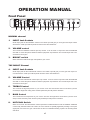
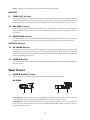
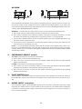
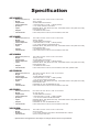
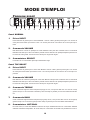
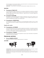
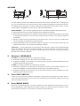
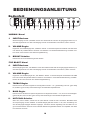
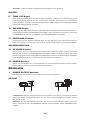
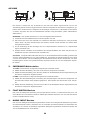
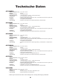
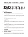
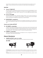
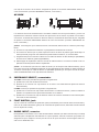
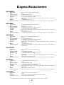
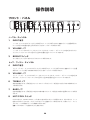
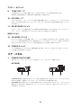
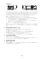
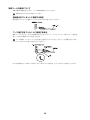
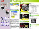
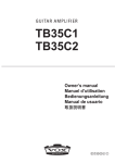
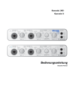
E F G S J 2
English............................................................................... 3
Français........................................................................... 10
Deutsch............................................................................ 16
Español............................................................................ 22
日本語.............................................................................. 28
2
IMPORTANT SAFETY INSTRUCTIONS
•• Read these instructions.
•• Keep these instructions.
•• Heed all warnings.
•• Follow all instructions.
•• Do not use this apparatus near water.
•• Mains powered apparatus shall not be exposed to dripping or
splashing and that no objects filled with liquids, such as vases,
shall be placed on the apparatus.
•• Clean only with dry cloth.
•• Do not block any ventilation openings. Install in accordance
with the manufacturer’s instructions.
•• Do not install near any heat sources such as radiators, heat
registers, stoves, or other apparatus (including amplifiers) that
produce heat.
•• Do not defeat the safety purpose of the polarized or groundingtype plug. A polarized plug has two blades with one wider
than the other. A grounding type plug has two blades and
a third grounding prong. The wide blade or the third prong
are provided for your safety. If the provided plug does not fit
into your outlet, consult an electrician for replacement of the
obsolete outlet. (for USA and Canada)
•• Protect the power cord from being walked on or pinched
particularly at plugs, convenience receptacles, and the point
where they exit from the apparatus.
•• Only use attachments/accessories specified by the
manufacturer.
•• Unplug this apparatus during lightning storms or when unused
for long periods of time.
•• Turning off the power switch does not completely isolate this
product from the power line so remove the plug from the
socket if not using it for extended periods of time.
•• Install this product near the wall socket and keep the power
plug easily accessible.
•• WARNING—This apparatus shall be connected to a mains
socket outlet with a protective earthing connection.
•• Refer all servicing to qualified service personnel. Servicing
is required when the apparatus has been damaged in any
way, such as power-supply cord or plug is damaged, liquid
has been spilled or objects have fallen into the apparatus, the
apparatus has been exposed to rain or moisture, does not
operate normally, or has been dropped.
•• Do not install this equipment on the far position from wall outlet
and/or convenience receptacle.
•• Do not install this equipment in a confined space such as a
box for the conveyance or similar unit.
•• Excessive sound pressure from earphones and headphones
can cause hearing loss.
•• Use only with the cart, stand, tripod, bracket, or table specified
by the manufacturer, or sold with the apparatus. When a
cart is used, use caution when moving the cart/apparatus
combination to avoid injury from tip-over.
The lightning flash with arrowhead symbol
within an equilateral triangle, is intended to
alert the user to the presence of uninsulated
“dangerous voltage” within the product’s enclosure that may be of sufficient magnitude to
constitute a risk of electric shock to persons.
The exclamation point within an equilateral
triangle is intended to alert the user to the
presence of important operating and maintenance (servicing) instructions in the literature
accompanying the product.
Notice regarding disposal (EU only)
When this “crossed-out wheeled bin” symbol is displayed on the product, owner’s manual, battery, or battery package, it signifies that when you wish to dispose
of this product, manual, package or battery you must do
so in an approved manner. Do not discard this product,
manual, package or battery along with ordinary household waste. Disposing in the correct manner will prevent
harm to human health and potential damage to the environment. Since the correct method of disposal will depend on
the applicable laws and regulations in your locality, please contact your local administrative body for details. If the battery
contains heavy metals in excess of the regulated amount, a
chemical symbol is displayed below the “crossed-out wheeled
bin” symbol on the battery or battery package.
*
3
All product names and company names are the trademarks
or registered trademarks of their respective owners.
4
Introduction
For many years, VOX has been designing and manufacturing some of the most renowned amplifiers in
recent history... Today is no exception. We’re honoured that you have chosen to add the AC Hand Wired
series to your sonic arsenal!
Beautifully hand built, using the finest components and custom parts to bring together the old and the
new.
This is classic VOX with a modern twist.
Not satisfied with just dusting off old designs, we have taken 2 of the most iconic channels of our AC30
(NORMAL and TOP BOOST) and given them a modern shake up.
The NORMAL channel is what you’d expect, pure and simple... VOLUME with a bright switch, to boost the
high end sparkle of your sound.
The TOP BOOST channel on the other hand has an alter ego... There are VOLUME, TREBLE and BASS
controls, but there is something extra... HOT...
COOL mode is classic VOX, HOT mode is something a little different. When in HOT, the TOP BOOST
channel is reconfigured for a more pure signal path, what this means to you is more gain... a lot more
GAIN! Best of all HOT can be engaged with the supplied VFS1 footswitch making it ideal for a lead boost
when you need to nail that solo...
Aside from the extra features in the individual channels, we have also added a TONE CUT and a fully
bypassable MASTER VOLUME meaning that if you need to play at lower volumes you can, but for unaffected tonal clarity, it can be removed completely, giving the bedroom guitarist and the tonal purist the
best of both worlds.
Finally, the output power can be cut in half using the OP MODE switch. In full power, you have all the
classic VOX sound you’d expect. In half power, the high end is mellowed slightly giving you a whole load
of new tonal characteristics to explore.
We believe this to be one of the most sonically versatile Hand Wired VOX amplifiers to date, and is well
on the way to joining its Grandfathers in the VOX hall of fame.
Enjoy!
VOX R&D Team
5
OPERATION MANUAL
Front Panel
1
2
3
4
5
6
7
8
9
10
11
12
13
NORMAL channel
1. INPUT Jack Sockets
Guitar input jacks for the NORMAL channel. The ‘HIGH’ input will give you more gain and output volume
whereas the ‘LOW’ input will be quieter and have more clean headroom.
2. VOLUME control
This controls the NORMAL Channel pre-amp volume. It can be used in conjunction with the MASTER
VOLUME to create the perfect balance between pre/power amp distortion and overall output level. Turn
clockwise for more gain.
3.
BRIGHT switch
When activated it adds more high-end sparkle to your sound.
TOP BOOST Channel
4.
INPUT Jack Sockets
Guitar input jacks for the TOP BOOST channel. The ‘HIGH’ input will give you more gain and output volume whereas the ‘LOW’ input will be quieter and have more clean headroom.
5.
VOLUME Control
This controls the TOP BOOST channel pre-amp volume. It can be used in conjunction with the MASTER
VOLUME to create the perfect balance between pre/power amp distortion and overall output level. Turn
clockwise for more gain.
6.
TREBLE Control
This controls the high frequencies in your sound—from soft and smooth when turned down (counter
clockwise) to bright and cutting when cranked (clockwise) and all points in-between.
7.
BASS Control
This controls the low frequencies in your sound—from thin and light when turned down (counter clockwise) to warm and heavy when turned up full (clockwise) and all points in-between.
8.
HOT/COOL Switch
When set to COOL the TOP BOOST channel operates in traditional fashion with the TREBLE and BASS
controls fully activated. When set to HOT, the tone controls are partially bypassed providing a more pure
signal path, and a boost in gain. This feature is also foot switchable making it perfect for boosting leads
and solos!
6
NOTE! When in HOT mode the tone controls still affect the sound slightly.
MASTER
9.
TONE CUT Control
This circuit is placed in the power amp as opposed to the pre-amp section like the TREBLE and BASS
controls. What this does is the opposite of what you may expect. Turning it clockwise will decrease the
higher frequencies. Use in conjunction with the TREBLE control to fine tune the high end of your sound.
10. VOLUME Control
This controls the overall or MASTER VOLUME of your amplifier. Use in conjunction with the NORMAL
and TOP BOOST volume controls to find the perfect balance between pre/power amp distortion and output volume.
11. MV/BYPASS switch
This switch allows you to completely remove the MASTER VOLUME control from the circuit. Giving the
tonal purist what they would expect from a vintage AC, but also allowing for lower volumes if needed.
OUTPUT Section
12. OP MODE Switch
This controls the output level of the power amplifier. When set to half power mode (15W AC30HW and 7.5W
AC15HW) the power amp distorts less and has a smooth high frequency roll off. When set to full power
mode (30W AC30HW and 15W AC15HW) the power amplifier breaks up at higher volumes and produces
a more harmonically dense sound.
13. POWER Switch
This is the ON/OFF switch for the amplifier. Please ensure the amplifier is switched off and unplugged before being moved.
Rear Panel
1. POWER OUTPUT jacks
This is where you can hook up an extension or external speaker cabinet(s) if desired.
AC15HW
1
2
3
4
EXTENSION SP: This speaker jack runs in parallel with the internal speaker which is 16 Ohms. The extension cabinet must be 16 Ohms and the IMPEDANCE switch should be set to 8 ohms.
EXTERNAL SP: This speaker jack will mute (disconnect) the internal speakers and you can hook up either a 16 Ohm or 8 Ohm cabinet. Be sure to set the IMPEDANCE SELECT switch accordingly. (See “IMPEDANCE SELECT Switch”)
7
AC30HW
1
2
3
4
The AC30HW internal speakers are connected via a speaker jack plug, they are wired for 16 Ohms. You
can connect another 16 ohm cabinet and run this in parallel with the internal speakers. If you want to disconnect the internal speakers simply unplug the jack. Be sure to set the IMPEDANCE SELECT switch accordingly. (See “IMPEDANCE SELECT Switch”)
WARNING! To ensure that your system works correctly, you must observe the following points.
a) Don’t use an extension cabinet whose impedance is anything other than 16 ohms.
b) Don’t connect a speaker whose rated input capacity is less than 30 watts (for AC30HW) or 15 watts
(AC15HW). The speaker may be destroyed if you ignore this caution—not recommended!
c) You must use a speaker cable to connect an external speaker. Don’t use a shielded cable like the one
you use to connect a guitar to an amp.
d) You must turn off the power before connecting the speaker cable. Connecting the cable while the
power is turned on may damage your amp.
NOTE! It is recommended that all audio cables (with the exception of the speaker lead), used to connect to the AC30HW/AC15HW are of a high quality, screened type. These should not exceed 10 metres
in length. Always use a non-screened VOX approved speaker lead with the AC30HW/AC15HW Amplifier
and extension cabinets.
2.
IMPEDANCE SELECT switch
16 OHMS: Combos allow for the following configurations:
a) Set it to this if you use the internal speakers only.
b) Set it to this if you connect an external 16 Ohm speaker cabinet through the External jack (internal
speakers disconnected).
8 OHMS: Combos allow for the following configurations:
a) Set it to this if you connect an extension cabinet. You’ll be running the internal and external speakers
in parallel. The impedance of the extension cabinet must be 16 Ohms.
b) Set it to this if you connect an external 8 ohm speaker cabinet through the External jack (internal
speakers disconnected).
3.
FOOT SWITCH jack
This is where you connect the included Foot Switch (VFS1) to switch between HOT and COOL modes on
the TOP BOOST Channel (HOT Mode must be engaged on the control panel for the Foot Switch to operate)
4.
MAINS INPUT connector
This is where the supplied, detachable Mains (power) cord is connected. The specific mains input voltage
rating that your amplifier needs to run at is located on the rear panel of your amplifier. Before making any
connections or powering up the amplifier, make sure the correct voltage is set. If you have any doubt, refer to your local VOX dealer.
8
Specification
AC30HW2X:
••
••
••
••
••
••
Dimensions (W x D x H)
Weight
Output Power
Tube Complement
Speakers
Inputs
•• Outputs
•• Included items
AC30HW2:
••
••
••
••
••
••
Dimensions (W x D x H)
Weight
Output Power
Tube Complement
Speakers
Inputs
•• Outputs
•• Included items
AC30HWH:
••
••
••
••
••
Dimensions (W x D x H)
Weight
Output Power
Tube Complement
Inputs
•• Outputs
•• Included items
AC15HW1X:
••
••
••
••
••
••
Dimensions (W x D x H)
Weight
Output Power
Tube Complement
Speakers
Inputs
•• Outputs
•• Included items
AC15HW1:
••
••
••
••
••
••
Dimensions (W x D x H)
Weight
Output Power
Tube Complement
Speakers
Inputs
•• Outputs
•• Included items
V212HWX:
••
••
••
••
Dimensions (W x D x H)
Weight
Speakers
Included items
705 x 260 x 550 mm / 27.76 x 10.24 x 21.65 inches
32 kg / 70.6lbs.
30 Watts RMS into 8/16 Ohms
3 x ECC83/12AX7, 4 x EL84, 1 x GZ34 (rectifier)
2 x 12" 8 Ohm Celestion Alnico Blue
NORMAL INPUT Jack (HIGH and LOW), TOP BOOST INPUT Jack (HIGH and LOW),
FOOT SWITCH Jack
2 x POWER OUTPUT Jacks
Power cable, Owner’s manual, VFS1 footswitch, Dust cover
705 x 260 x 550 mm / 27.76 x 10.24 x 21.65 inches
30.8 kg / 67.9lbs.
30 Watts RMS into 8/16 Ohms
3 x ECC83/12AX7, 4 x EL84, 1 x GZ34 (rectifier)
2 x 12" 8 Ohm Celestion G12M Green Back
NORMAL INPUT Jack (HIGH and LOW), TOP BOOST INPUT Jack (HIGH and LOW),
FOOT SWITCH Jack
2 x POWER OUTPUT Jacks
Power cable, Owner’s manual, VFS1 footswitch, Dust cover
705 x 260 x 250 mm / 27.76 x 10.24 x 9.84 inches
18.8 kg / 41.5lbs.
30 Watts RMS into 8/16 Ohms
3 x ECC83/12AX7, 4 x EL84, 1 x GZ34 (rectifier)
NORMAL INPUT Jack (HIGH and LOW), TOP BOOST INPUT Jack (HIGH and LOW),
FOOT SWITCH Jack
2 x POWER OUTPUT Jacks
Power cable, Owner’s manual, VFS1 footswitch, Dust cover, Speaker cable
610 x 260 x 550 mm / 24.02 x 10.24 x 21.65 inches
22.8 kg / 50.3 lbs.
15 Watts RMS into 8/16 Ohms
3 x ECC83/12AX7, 2 x EL84, 1 x EZ81 (rectifier)
1 x 12" 16 Ohm Celestion Alnico Blue
NORMAL INPUT Jack (HIGH and LOW), TOP BOOST INPUT Jack (HIGH and LOW),
FOOT SWITCH Jack
External SP Jack, Extension SP Jack
Power cable, Owner’s manual, VFS1 footswitch, Dust cover
610 x 260 x 550 mm / 24.02 x 10.24 x 21.65 inches
22.2 kg / 48.9 lbs.
15 Watts RMS into 8/16 Ohms
3 x ECC83/12AX7, 2 x EL84, 1 x EZ81 (rectifier)
1 x 12" 16 Ohm Celestion G12M Green Back
NORMAL INPUT Jack (HIGH and LOW), TOP BOOST INPUT Jack (HIGH and LOW),
FOOT SWITCH Jack
External SP Jack, Extension SP Jack
Power cable, Owner’s manual, VFS1 footswitch, Dust cover
705 x 260 x 550 mm / 27.76 x 10.24 x 21.65 inches
20.3kg / 44.8lbs
2 x 12" 8 Ohm Celestion Alnico Blue / 30 Watts RMS into 16 Ohms
Owner’s manual, Dust cover
* Specifications and appearance are subject to change without notice for improvement.
9
INFORMATIONS IMPORTANTES DE SECURITE
•• Lisez attentivement ces instructions.
•• Veuillez conserver ces instructions.
•• Observez tous les avertissements.
•• Suivez toutes les consignes à la lettre.
•• N’utilisez jamais cet appareil dans un endroit humide ni à
proximité d’eau.
•• L’appareil alimenté par courant électrique ne peut pas être
exposé à des éclaboussures; évite en outre de placer des
récipients contenant des liquides, comme un vase (ou un verre
de bière), sur l’appareil.
•• Nettoyez uniquement l’appareil avec un chiffon doux et sec.
•• Ne bloquez jamais les orifices de ventilation de l’appareil
et installez-le toujours conformément aux instructions du
fabricant.
•• N’installez jamais l’appareil à proximité d’une source de
chaleur, telle que des radiateurs, poêles ou tout autre dispositif
(y compris des amplificateurs) générant de la chaleur.
•• N’essayez jamais de contourner le dispositif de sécurité d’une
prise de type polarisée ou d’une prise de terre. Une prise dite
polarisée dispose de deux broches, dont l’une est plus large
que l’autre. Une prise de terre comporte trois broches, dont
une de mise à la terre. Cette broche plus large ou broche de
mise à la terre vise à assurer votre sécurité. Si la fiche du
cordon d’alimentation ne correspond pas au type de prise de
courant de votre région, faites remplacer la prise obsolète par
un électricien qualifié (pour les Etats-Unis et le Canada).
•• Placez toujours le cordon d’alimentation de sorte qu’on ne
risque pas de marcher dessus ni de le pincer. Cette précaution
vise tout spécialement la fiche du cordon et sa sortie de
l’appareil.
•• Utilisez exclusivement les fixations/accessoires préconisés par
le fabricant.
•• S’il y a risque d’orage ou que vous ne comptez pas utiliser
l’appareil pendant une période prolongée, débranchez-le du
secteur.
•• La mise sur OFF de l’interrupteur d’alimentation n’isole pas
totalement ce produit de la ligne secteur; aussi, retirez la
fiche de la prise s’il doit rester inutilisé pendant une période
prolongée.
•• Installez ce produit près de la prise électrique murale et gardez
un accès facile à la prise électrique et au cordon d’alimentation.
•• ATTENTION: Cet appareil doit absolument être connecté à
une prise électrique reliée à la terre.
•• Confiez tout travail de réparation uniquement à un S.A.V.
qualifié. Faites appel au S.A.V. si l’appareil a subi tout
endommagement, comme par exemple si sa fiche secteur
ou son cordon d’alimentation sont endommagés, si de l’eau
ou des objets ont pénétré à l’intérieur de l’appareil, si celuici a été exposé à la pluie ou à la moisissure, s’il est tombé ou
présente tout signe de dysfonctionnement.
•• N’utilisez jamais d’allonge trop longue avec cet appareil et
ne l’alimentez jamais via les prises secteur équipant d’autres
dispositifs.
•• N’installez jamais cet appareil dans un endroit confiné comme
une caisse de transport ou tout autre récipient similaire.
•• Des niveaux d’écoute trop importants lors de l’utilisation d’un
casque ou d’écouteurs peuvent entraîner des pertes d’audition.
•• Utilisez l’appareil uniquement avec le chariot, stand, trépied,
fixation ou table spécifiés par le fabricant ou fourni avec
l’appareil. Si vous avez placé l’appareil sur un chariot, soyez
très prudent quand vous déplacez le chariot, afin d’éviter une
chute et des blessures.
L’éclair dans le triangle est un symbole destiné
à attirer l’attention de l’utilisateur sur la présence de parties non isolées et de “tension dangereuse” à l’intérieur de l’appareil, qui posent des
risques d’électrocution pour l’utilisateur.
Le point d’exclamation dans un triangle est un
symbole destiné à attirer l’attention de l’utilisateur sur des sections de ce manuel contenant
des informations importantes, liées à l’utilisation et à l’entretien de ce produit.
Note concernant les dispositions (Seulement EU)
Quand un symbole avec une poubelle barrée d’une
croix apparait sur le produit, le mode d’emploi, les piles ou le pack de piles, cela signifie que ce produit,
manuel ou piles doit être déposé chez un représentant
compétent, et non pas dans une poubelle ou toute
autre déchetterie conventionnelle.
Disposer de cette manière, de prévenir les dommages
pour la santé humaine et les dommages potentiels
pour l’environnement. La bonne méthode d’élimination dépendra des lois et règlements applicables dans votre localité,
s’il vous plaît, contactez votre organisme administratif pour
plus de détails. Si la pile contient des métaux lourds au-delà
du seuil réglementé, un symbole chimique est affiché en dessous du symbole de la poubelle barrée d’une croix sur la pile
ou le pack de piles.
*
10
Tous les noms de produits et de sociétés sont des marques
commerciales ou déposées de leur détenteur respectif.
Introduction
Cela fait des années que VOX conçoit et fabrique des amplificateurs comptant parmi les plus célèbres et
les plus convoités au monde. Celui-ci n’y fait pas exception. Nous sommes honorés que vous ayez opté
pour la série AC Hand Wired!
Fabriquée à la main avec les meilleurs composants et des pièces taillées sur mesure, cette série conjugue passé et présent pour préparer l’avenir.
Elle propose un VOX classique d’une modernité inédite.
Non contents de dépoussiérer d’anciens modèles, nous avons repris les 2 canaux les plus prisés de notre
AC30 (NORMAL et TOP BOOST) pour leur donner un flair plus actuel.
Le canal NORMAL répond à toutes vos attentes, purement et simplement… Commande VOLUME et
commutateur BRIGHT accentuant l’éclat du son dans l’aigu.
Le canal TOP BOOST, par contre, est doté d’un alter ego… En plus des commandes VOLUME, TREBLE
et BASS, il a quelque chose de plus… CHAUD…
Le mode COOL correspond au VOX classique alors que le mode HOT est un peu différent. En mode
HOT, le canal TOP BOOST est reconfiguré pour dégager l’acheminement du signal et délivrer ainsi plus
de gain… bien plus de GAIN! Cerise sur le gâteau, le mode HOT peut être activé avec la pédale commutateur VFS1 fournie: une simple pression du pied booste le son pour un inoubliable solo…
En plus des nouveautés au niveau des canaux individuels, nous avons aussi ajouté une commande
TONE CUT et une commande MASTER VOLUME entièrement contournable: cela signifie que si vous
devez jouer à un volume plus bas, vous le pouvez mais, si vous tenez à la clarté du son, cette commande
peut être supprimée, offrant ainsi le meilleur des deux mondes au guitariste de chambre et au puriste.
Enfin, la puissance de sortie peut être divisée par deux avec le commutateur OP MODE. En mode pleine
puissance, vous obtenez le son VOX classique. A mi-puissance, l’aigu est légèrement adouci et propose
toute une nouvelle palette de caractéristiques tonales à explorer.
Nous sommes convaincus que cet amplificateur est, du point de vue sonore, l’un des plus flexibles de la
série Hand Wired VOX et qu’il est en passe de rejoindre ses illustres prédécesseurs au panthéon VOX.
Bon amusement!
L’équipe R&D de VOX
11
MODE D’EMPLOI
Panneau avant
1
2
3
4
5
6
7
8
9
10
11
12
13
Canal NORMAL
1.
Prises INPUT
Prises d’entrée de guitare pour le canal NORMAL. L’entrée “HIGH” génère plus de gain et un niveau de
sortie plus élevé tandis que l’entrée “LOW” a un niveau plus bas et une réserve de son clair plus importante.
2.
Commande VOLUME
Elle détermine le volume du préampli du canal NORMAL. Elle peut être combinée avec la commande
MASTER VOLUME pour créer une balance parfaite entre la distorsion du préampli/ampli de puissance et
le niveau de sortie global. Tournez-la vers la droite pour augmenter le gain.
3.
Commutateur BRIGHT
L’activation de ce commutateur ajoute plus d’éclat dans l’aigu.
Canal TOP BOOST
4.
Prises INPUT
Prises d’entrée de guitare pour le canal TOP BOOST. L’entrée “HIGH” génère plus de gain et un niveau
de sortie plus élevé tandis que l’entrée “LOW” a un niveau plus bas et une réserve de son clair plus importante.
5.
Commande VOLUME
Elle détermine le volume du préampli du canal TOP BOOST. Elle peut être combinée avec la commande
MASTER VOLUME pour créer une balance parfaite entre la distorsion du préampli/ampli de puissance et
le niveau de sortie global. Tournez-la vers la droite pour augmenter le gain.
6.
Commande TREBLE
Cette commande règle les hautes fréquences (l’aigu) du son; vous pouvez aller d’un son doux et rond (à
gauche toute) à un son tranchant et éclatant (à fond à droite) en passant par tous les stades intermédiaires.
7.
Commande BASS
Cette commande règle les basses fréquences (le grave) du son; vous pouvez aller d’un son fin et léger (à
gauche toute) à un son chaud et gras (à fond à droite) en passant par tous les stades intermédiaires.
8.
Commutateur HOT/COOL
En mode COOL, le canal TOP BOOST fonctionne de façon traditionnelle avec les commandes TREBLE
et BASS entièrement disponibles. En mode HOT, les commandes de tonalité sont partiellement contour-
12
nées pour dégager la voie du signal et délivrer un gain plus important. Ce mode peut être activé du pied,
ce qui est idéal pour un passage en force du solo!
ATTENTION: En mode HOT, les commandes de tonalité gardent une légère influence sur le son.
MASTER
9.
Commande TONE CUT
Ce circuit fait partie de l’ampli de puissance et non de l’étage du préampli dont relèvent les commandes
TREBLE et BASS, par exemple. Il fait le contraire de ce que vous pensez. Plus vous tournez la commande vers la droite, plus les hautes fréquences diminuent. Combinez-la avec la commande TREBLE pour
affiner le réglage de l’aigu.
10. Commande VOLUME
Elle détermine le volume global (MASTER VOLUME) de l’amplificateur. Elle peut être combinée avec la
commande de volume du canal NORMAL ou TOP BOOST pour créer une balance parfaite entre la distorsion du préampli/ampli de puissance et le niveau de sortie.
11. Commutateur MV/BYPASS
Ce commutateur peut supprimer complètement la commande MASTER VOLUME du circuit. Il permet
ainsi au puriste de retrouver un véritable AC vintage mais permet également de jouer à bas volume si nécessaire.
Section de sortie
12. Commutateur OP MODE
Ce commutateur détermine le niveau de sortie de l’amplificateur de puissance. A mi-puissance (15W pour
l’AC30HW et 7,5W pour l’AC15HW), l’ampli de puissance affiche une distorsion moindre et atténue l’aigu
en douceur. A pleine puissance (30W pour l’AC30HW et 15W pour l’AC15HW), l’ampli de puissance sature à volume élevé et délivre un son harmoniquement plus dense.
13. Commutateur POWER
Commutateur de mise sous/hors tension de l’amplificateur. Coupez toujours l’alimentation de l’amplificateur
et débranchez-le avant de le déplacer.
Panneau arrière
1.
Prises POWER OUTPUT
Vous pouvez y brancher une (des) enceinte(s) d’extension ou externe(s).
AC15HW
1
2
3
4
EXTENSION SP: Cette sortie pour enceinte est parallèle au haut-parleur interne qui fait 16Ω. L’enceinte
d’extension doit donc faire 16Ω et le sélecteur IMPEDANCE doit être réglé sur “8Ω”.
EXTERNAL SP: Cette sortie coupe (déconnecte) le haut-parleur interne et vous pouvez utiliser une enceinte de 16Ω ou 8Ω. Réglez alors correctement le sélecteur IMPEDANCE (voyez la section “Sélecteur
IMPEDANCE”).
13
AC30HW
1
2
3
4
Les haut-parleurs internes de l’AC30HW sont branchés par une fiche d’enceinte avec un câblage pour
16Ω. Vous pouvez brancher une autre enceinte de 16Ω et l’utiliser en parallèle aux haut-parleurs internes.
Pour débrancher les haut-parleurs internes, débranchez simplement la fiche. Réglez ensuite correctement le sélecteur IMPEDANCE (voyez la section “Sélecteur IMPEDANCE”).
AVERTISSEMENT: Pour que votre système fonctionne correctement, respectez les points suivants.
a) Utilisez exclusivement une enceinte d’extension dont l’impédance est de 16Ω.
b) Ne branchez pas d’enceinte dont la capacité d’entrée nominale est inférieure à 30W (pour l’AC30HW)
ou 15W (pour l’AC15HW). Si vous ne tenez pas compte de cette remarque, vous risquez de détruire le
haut-parleur!
c) Utilisez un câble d’enceinte pour brancher une enceinte externe. Ne vous servez pas de câble blindé
comme celui utilisé pour brancher une guitare à ampli.
d) Coupez l’alimentation avant de brancher le câble de l’enceinte. Si vous branchez le câble alors que
l’ampli est sous tension, vous risquez d’endommager ce dernier.
ATTENTION: Tous les câbles audio, à l’exception du câble d’enceinte, utilisés avec l’AC30HW/AC15HW
doivent de préférence être de bonne qualité et blindés. Ils ne peuvent excéder 10 mètres de longueur.
Servez-vous toujours d’un câble d’enceinte non blindé approuvé par VOX pour relier l’ampli AC30HW/
AC15HW et les enceintes d’extension.
2.
Sélecteur IMPEDANCE
16 OHMS: Les combos permettent les configurations suivantes:
a) Choisissez ce réglage si vous n’utilisez que les haut-parleurs internes.
b) Choisissez ce réglage si vous branchez une enceinte externe de 16Ω à la prise EXTERNAL (les hautparleurs internes sont déconnectés).
8 OHMS: Les combos permettent les configurations suivantes:
a) Choisissez ce réglage si vous branchez une enceinte d’extension. Les haut-parleurs internes et externes sont parallèles. L’enceinte d’extension doit donc avoir une impédance de 16Ω.
b) Choisissez ce réglage si vous branchez une enceinte externe de 8Ω à la prise EXTERNAL (les hautparleurs internes sont déconnectés).
3.
Prise FOOT SWITCH
C’est ici que vous branchez la pédale commutateur fournie (VFS1) pour alterner les modes “HOT” et
“COOL” du canal TOP BOOST (le mode “HOT” doit être sélectionné sur le panneau avant pour que la pédale commutateur fonctionne).
4.
Prise MAINS INPUT
Prise pour le câble d’alimentation. La tension indiquée pour votre amplificateur est précisée en face arrière de l’amplificateur. Avant d’effectuer la moindre connexion ou de mettre l’ampli sous tension, vérifiez
que la tension est correcte. En cas de doute, contactez votre revendeur VOX.
14
Fiche technique
AC30HW2X:
••
••
••
••
••
••
Dimensions (L x P x H) Poids Puissance de sortie Lampes Haut-parleurs Entrées •• Sorties •• Livré avec
AC30HW2:
••
••
••
••
••
••
Dimensions (L x P x H) Poids Puissance de sortie Lampes Haut-parleurs Entrées •• Sorties •• Livré avec
AC30HWH:
••
••
••
••
••
Dimensions (L x P x H) Poids Puissance de sortie Lampes Entrées •• Sorties •• Livré avec
AC15HW1X:
••
••
••
••
••
••
Dimensions (L x P x H) Poids Puissance de sortie Lampes Haut-parleurs Entrées •• Sorties •• Livré avec
AC15HW1:
••
••
••
••
••
••
Dimensions (L x P x H) Poids Puissance de sortie Lampes Haut-parleurs Entrées
•• Sorties •• Livré avec
V212HWX:
••
••
••
••
Dimensions (L x P x H) Poids Haut-parleurs Livré avec
705 x 260 x 550mm
32,0kg
30W RMS sous 8/16Ω
3 x ECC83/12AX7, 4 x EL84, 1 x GZ34 (redresseur)
Celestion Alnico Blue 2x12” 8Ω
Prises INPUT HIGH et LOW (canal NORMAL), Prises INPUT HIGH et LOW (canal
TOP BOOST), Prise FOOT SWITCH
2 prises POWER OUTPUT
Câbles d’alimentation, Pédale VFS1, Manuel d’utilisation Housse anti-poussière
705 x 260 x 550mm
30,8kg
30W RMS sous 8/16Ω
3 x ECC83/12AX7, 4 x EL84, 1 x GZ34 (redresseur)
Celestion G12M Green Back 2x12” 8Ω
Prises INPUT HIGH et LOW (canal NORMAL), Prises INPUT HIGH et LOW (canal
TOP BOOST), Prise FOOT SWITCH
2 prises POWER OUTPUT
Câbles d’alimentation, Pédale VFS1, Manuel d’utilisation, Housse anti-poussière
705 x 260 x 250mm
18,8kg
30W RMS sous 8/16Ω
3 x ECC83/12AX7, 4 x EL84, 1 x GZ34 (redresseur)
Prises INPUT HIGH et LOW (canal NORMAL), Prises INPUT HIGH et LOW (canal
TOP BOOST), Prise FOOT SWITCH
2 prises POWER OUTPUT
Câbles d’alimentation, Pédale VFS1, Manuel d’utilisation, Housse anti-poussière, câble pour haut-parleur
610 x 260 x 550mm
22,8kg
15W RMS sous 8/16Ω
3 x ECC83/12AX7, 2 x EL84, 1 x EZ81 (redresseur)
Celestion Alnico Blue 1x12” 16Ω
Prises INPUT HIGH et LOW (canal NORMAL), Prises INPUT HIGH et LOW (canal
TOP BOOST), Prise FOOT SWITCH
Prise EXTERNAL SP, Prise EXTENSION SP
Câbles d’alimentation, Pédale VFS1, Manuel d’utilisation, Housse anti-poussière
610 x 260 x 550mm
22,2kg
15W RMS sous 8/16Ω
3 x ECC83/12AX7, 2 x EL84, 1 x EZ81 (redresseur)
Celestion G12M Green Back 1x12” 16Ω
Prises INPUT HIGH et LOW (canal NORMAL), Prises INPUT HIGH et LOW (canal
TOP BOOST), Prise FOOT SWITCH
Prise EXTERNAL SP, Prise EXTENSION SP
Câbles d’alimentation, Pédale VFS1, Manuel d’utilisation, Housse anti-poussière
705 x 260 x 550mm
20,3kg
Celestion Alnico Blue 2x12” 8Ω / 30W RMS sous 16Ω
Manuel d’utilisation, Housse anti-poussière
* Les caractéristiques et l’aspect du produit sont susceptibles d’être modifiés sans avis préalable en vue d’une amélioration.
15
WICHTIGE SICHERHEITSHINWEISE
•• Bitte lesen Sie sich alle Bedienhinweise durch.
•• Bewahren Sie diese Bedienhinweise auf.
•• Beachten Sie alle Warnungen.
•• Befolgen Sie alle Instruktionen.
•• Verwenden Sie dieses Gerät niemals in der Nähe von Wasser.
•• Ein netzgespeistes Gerät darf niemals Regen- oder
Wassertropfen ausgesetzt werden. Außerdem darf man keine
Flüssigkeitsbehälter wie Vasen usw. darauf stellen.
•• Reinigen Sie es ausschließlich mit einem trockenen Tuch.
•• Versperren Sie niemals die Lüftungsschlitze und stellen Sie
das Gerät nur an Orten auf, die vom Hersteller ausdrücklich
empfohlen werden.
•• Stellen Sie das Gerät niemals in die Nähe einer Wärmequelle,
z.B. eines Heizkörpers, Ofens oder eines anderen Wärme
erzeugenden Gerätes (darunter auch Endstufen).
•• Versuchen Sie niemals, die polarisierte Leitung bzw. Erde
hochzulegen oder zu umgehen. Ein polarisierter Stecker ist
mit zwei flachen Stiften unterschiedlicher Breite versehen. Ein
Stecker mit Erdung weist zwei Stifte und eine Erdungsbuchse
auf. Wenn der beiliegende Stecker nicht in Ihre Steckdose
passt, sollten Sie einen Elektriker bitten, die Steckdose zu
erneuern (für die USA und Kanada).
•• Sorgen Sie dafür, dass man weder über das Netzkabel
stolpern kann, noch dass es in unmittelbarer Nähe einer
Steckdose, darunter auch Zusatzsteckdosen anderer Geräte,
abgeklemmt wird. Auch am Austritt aus dem Gerät darf das
Netzkabel auf keinen Fall gequetscht werden.
•• Verwenden Sie nur Halterungen/Zubehör, die/das vom
Hersteller ausdrücklich empfohlen werden/wird.
•• Im Falle eines Gewitters bzw. wenn Sie das Gerät längere Zeit
nicht verwenden möchten, lösen Sie bitte den Netzanschluss.
•• Durch Ausschalten des Hauptschalters wird dieses Erzeugnis
nicht vollständig vom Netz getrennt. Ziehen Sie deshalb den
Stecker des Netzkabels aus der Steckdose, wenn Sie das
Erzeugnis längere Zeit nicht verwenden.
•• Stellen Sie diesen Verstärker in der Nähe einer Wand
Schutzkontaktdose auf und achten Sie auf die freie
Zugänglichkeit des Netzanschlusskabels.
•• Warnhinweis: Dieser Verstärker darf nur an Steckdosen mit
Schutzleiter (Erdung) betrieben werden.
•• Überlassen Sie alle Wartungsarbeiten einem erfahrenen
Wartungstechniker. Wartungsarbeiten oder Reparaturen
sind erforderlich, wenn das Netzkabel oder der Stecker
beschädigt ist, wenn Flüssigkeit oder andere Gegenstände
in das Geräteinnere gefallen sind, wenn das Gerät im Regen
gestanden hat, sich nicht erwartungsgemäß verhält oder wenn
es gefallen ist.
•• Stellen Sie das Gerät niemals unmittelbar neben die
Steckdose und/oder Erweiterungssteckdose eines anderen
Geräts.
•• Stellen Sie das Gerät während des Betriebes niemals in einen
Türschrank oder den Lieferkarton.
•• Hohe Schallpegel bei Verwendung eines großen oder kleinen
Kopfhörers können Hörschäden verursachen.
•• Stellen Sie das Gerät nur auf einen Wagen, Ständer, Stative,
Halterungen oder Tische, die vom Hersteller ausdrücklich
empfohlen werden oder eventuell zum Lieferumfang gehören.
Seien Sie beim Verschieben eines geeigneten Wagens
vorsichtig, damit weder er, noch das Gerät selbst umkippt bzw.
hinfällt und Sie eventuell verletzt.
Der als Pfeil dargestellte Blitz in einem Dreieck
weist den Anwender auf nicht isolierte, „gefährliche Spannungen“ im Geräteinneren hin, die
so stark sein können, dass sie einen Stromschlag verursachen.
Das Ausrufezeichen in einem Dreieck weist
den Anwender darauf hin, dass zum Lieferumfang des Gerätes wichtige Bedien- und Wartungshinweise (eventuell Reparaturhinweise)
gehören.
Hinweis zur Entsorgung (Nur EU)
Wenn Sie das Symbol mit der „durchgekreuzten Mülltonne“ auf Ihrem Produkt, der dazugehörigen Bedienungsanleitung, der Batterie oder dem Batteriefach
sehen, müssen Sie das Produkt in der vorgeschriebenen Art und Weise entsorgen. Dies bedeutet, dass
dieses Produkt mit elektrischen und elektronischen
Komponenten nicht mit dem normalen Hausmüll entsorgt werden darf. Für Produkte dieser Art existiert
ein separates, gesetzlich festgelegtes Entsorgungssystem.
Gebrauchte elektrische und elektronische Geräte müssen
separat entsorgt werden, um ein umweltgerechtes Recycling
sicherzustellen. Diese Produkte müssen bei benannten Sammelstellen abgegeben werden. Die Entsorgung ist für den
Endverbraucher kostenfrei! Bitte erkundigen sie sich bei ihrer
zuständigen Behörde, wo sie diese Produkte zur fachgerechten Entsorgung abgeben können.
Falls ihr Produkt mit Batterien oder Akkumulatoren ausgerüstet ist, müssen sie diese vor Abgabe des Produktes
entfernen und separat entsorgen (siehe oben). Die Abgabe
dieses Produktes bei einer zuständigen Stelle hilft ihnen,
dass das Produkt umweltgerecht entsorgt wird. Damit leisten
sie persönlich einen nicht unerheblichen Beitrag zum Schutz
der Umwelt und der menschlichen Gesundheit vor möglichen
negativen Effekten durch unsachgemäße Entsorgung von
Müll. Batterien oder Akkus, die Schadstoffe enthalten, sind
auch mit dem Symbol einer durchgekreuzten Mülltonne gekennzeichnet. In der Nähe zum Mülltonnensymbol befindet
sich die chemische Bezeichnung des Schadstoffes.
Cd oder NiCd steht für Cadmium, Pb für Blei und Hg für
Quecksilber.
*
16
Alle Produkt- und Firmennamen sind Warenzeichen oder
eingetragene Warenzeichen der betreffenden Eigentümer.
Vorweg
Seit Jahrzehnten entwickelt und baut VOX Verstärker, die unweigerlich Geschichte schreiben… Und das
wollen wir auch in Zukunft so halten. Aber natürlich freuen wir uns noch viel mehr über Ihre Entscheidung
zu einem Verstärker der AC Hand Wired-Serie!
Diese handgefertigten Amps enthalten die besten zur Zeit verfügbaren Komponenten und klingen wahlweise wie ein „Vintage“- oder ein neuzeitlicher Verstärker.
Das klassische VOX-Erbe wird hier mit der Moderne verquickt.
Wir wollten Ihnen nämlich mehr bieten als eine voll funktionstüchtige Neuauflage. Hier stehen Ihnen 2 der
legendären AC30-Kanäle zur Verfügung („NORMAL“ und „TOP BOOST“), die mehr können als die hehren Originale.
Der „NORMAL“-Kanal klingt dank eines schnörkellosen Designs erfreulich „clean“: Außer VOLUME und
einem BRIGHT-Schalter für einen brillanteren Sound beeinflusst rein gar nichts das Gitarrensignal.
Der TOP BOOST-Kanal kann auf zwei Arten verwendet werden… Außer den Reglern VOLUME, TREBLE
und BASS gibt es hier nämlich noch etwas – etwas HEISSES…
Der COOL-Modus klingt eindeutig nach VOX, der HOT-Modus dagegen ist neu im Geschmacksprogramm. Im HOT-Modus wird der Signalweg des „TOP BOOST“-Kanals nämlich „reiner“ gestaltet, was
sich positiv auf die Pegelanhebung auswirkt—viel mehr GAIN also! Den HOT-Modus kann man übrigens
mit dem beiliegenden VFS1 Fußtaster aktivieren, so dass Ihre Soli keinem Zuhörer mehr entgehen.
Zusätzlich zu den neuen Funktionen der Kanäle haben wir die Amps mit einer TONE CUT-Schaltung und
einem MASTER VOLUME-Regler mit Bypass ausgestattet. Letzterer braucht also nur aktiv zu sein, wenn
Sie niemanden stören dürfen. Solange der Schallpegel kein Thema ist, können Sie ihn dagegen aus dem
Signalweg entfernen.
Ferner gibt es einen OP MODE-Schalter, mit dem die Ausgangsleistung halbiert werden kann. Bei normaler Leistung klingt Ihr Amp, wie Sie es bei einem VOX voraussetzen. Bei halbierter Leistung ist der Sound
dagegen runder—und wartet mit neuen Klangalternativen auf.
Unserer bescheidenen Meinung nach verfügen Sie jetzt über einen der besten handgefertigten VOXVerstärker aller Zeiten, der schon bald mit seinen illustren Vorfahren in einem Atemzug genannt werden
wird.
Viel Spaß!
Ihr VOX R&D-Team
17
BEDIENUNGSANLEITUNG
Bedienfeld
1
2
3
4
5
6
7
8
9
10
11
12
13
‘NORMAL’-Kanal
1.
INPUT-Buchsen
Gitarreneingänge für den „NORMAL“-Kanal. Die HIGH-Buchse hebt den Eingangspegel stärker an, so
dass das Signal lauter wird. Der LOW-Eingang ist leiser und bietet daher eine höhere „Clean“ Reserve.
2.
VOLUME-Regler
Regelt den Vorverstärkerpegel des „NORMAL“-Kanals. Im Zusammenspiel mit MASTER VOLUME kann
man hiermit die perfekte Balance zwischen Vorverstärker- und Endstufenübersteuerung einstellen. Drehen Sie ihn nach rechts für eine stärkere Pegelanhebung.
3. BRIGHT-Schalter
Hiermit kann der Sound brillanter gemacht werden.
‘TOP BOOST’-Kanal
4. INPUT-Buchsen
Gitarreneingänge für den „TOP BOOST“-Kanal. Die HIGH-Buchse hebt den Eingangspegel stärker an, so
dass das Signal lauter wird. Der LOW-Eingang ist leiser und bietet daher eine höhere „cleane“ Reserve.
5. VOLUME-Regler
Regelt den Vorverstärkerpegel des „TOP BOOST“-Kanals. Im Zusammenspiel mit MASTER VOLUME
kann man hiermit die perfekte Balance zwischen Vorverstärker- und Endstufenübersteuerung einstellen.
Drehen Sie ihn nach rechts für eine stärkere Pegelanhebung.
6. TREBLE-Regler
Hiermit können die Höhen angehoben und abgesenkt werden – von „geschmeidig und rund“ (ganz links)
bis „beißend“ (ganz rechts). Zwischenlösungen sind ebenfalls empfehlenswert.
7. BASS-Regler
Hiermit können die tiefen Frequenzen angehoben und abgesenkt werden – von „dünn und unaufdringlich“
(ganz links) bis „warm und fett“ (ganz rechts). Zwischenlösungen sind ebenfalls empfehlenswert.
8.
HOT/COOL-Schalter
Wenn Sie „COOL“ wählen, verhält sich der „TOP BOOST“-Kanal wie seine Vorfahren. Bei Bedarf kann
der Frequenzgang mit dem TREBLE- und BASS-Regler geändert werden. In der „HOT“-Einstellung werden die Klangregler dagegen teilweise umgangen, was einen reineren Signalweg und mehr Gain zur Folge hat. Diese Funktion kann mit einem Fußtaster aktiviert/ausgeschaltet werden und empfiehlt sich daher
für Lead-Parts und Soli!
18
ACHTUNG! Selbst im HOT-Modus beeinflussen die Klangregler noch den Sound.
MASTER
9. TONE CUT-Regler
Diese Schaltung befindet sich in der Endstufe (während TREBLE und BASS im Vorverstärker wirken). Der
Regler tut genau das Gegenteil von dem, was der Name verspricht: Wenn Sie ihn nach rechts drehen,
werden die Höhen abgesenkt. Im Zusammenspiel mit dem TREBLE-Regler können Sie hiermit exakt die
gewünschte Höhenwiedergabe einstellen.
10. VOLUME-Regler
Hiermit kann die allgemeine Ausgangslautstärke (MASTER VOLUME) des Amps eingestellt werden. Im
Zusammenspiel mit dem Lautstärkeregler des „NORMAL“- oder „TOP BOOST“-Kanals kann man hiermit
die perfekte Balance zwischen Vorverstärker- und Endstufenübersteuerung einstellen.
11. MV/BYPASS-Schalter
Hiermit können Sie den MASTER VOLUME-Regler aus dem Signalweg holen. Das entspricht dem Verhalten eines „Vintage“-AC. Wenn Sie an die Nachbarn denken müssen, aktivieren Sie ihn einfach wieder.
AUSGANGSSEKTION
12. OP MODE-Schalter
Hiermit regeln Sie den Ausgangspegel der Endstufe. Bei Anwahl der halben Leistung (15W beim
AC30HW bzw. 7,5W beim AC15HW) übersteuert die Endstufe weniger und klingt auch einen Tick runder.
Bei Verwendung der vollen Leistung (30W beim AC30HW bzw. 15W beim AC15HW) beginnt die Endstufe
bei höheren Pegeln zu zerren und reichert den Sound mit weiteren Obertönen an.
13. POWER-Schalter
Hiermit wird der Verstärker ein- und ausgeschaltet. Vor Lösen des Netzanschlusses und dem anschließenden Transport müssen Sie den Amp unbedingt ausschalten.
Rückseite
1.
POWER OUTPUT-Buchsen
Hier können Sie eine Erweiterungs- und/oder eine externe Box anschließen.
AC15HW
1
2
3
4
EXTENSION SP: Eine hier angeschlossene Box wird parallel zu den internen Lautsprechern getrieben
(16Ω). Die Impedanz der externen Box muss zwar 16Ω lauten, aber der IMPEDANCE-Schalter muss auf
„8Ω“ gestellt werden.
EXTERNAL SP: Eine hier angeschlossene Box (16Ω oder 8Ω) schaltet den/die internen Lautsprecher
stumm. Vergessen Sie nicht, den IMPEDANCE-Schalter richtig einzustellen. (Siehe „IMPEDANCE-Wahlschalter“)
19
AC30HW
1
2
3
4
Die internen Lautsprecher des AC30HW sind mit Hilfe einer Klinke angeschlossen und für den
16Ω-Betrieb gedacht. Eine hier angeschlossene 16Ω-Box wird parallel zu den internen Lautsprechern getrieben. Wenn Sie die internen Lautsprecher nicht benötigen, brauchen Sie nur die Klinke aus der Buchse
zu ziehen. Vergessen Sie nicht, den IMPEDANCE-Schalter richtig einzustellen. (Siehe „IMPEDANCEWahlschalter“)
WARNUNG! Das System funktioniert nur, wenn Sie folgende Punkte beachten.
a) Verwenden Sie ausschließlich Boxen mit einer Impedanz von 16Ω.
b) Die externe Box muss eine Kapazität von mindestens 30W (beim AC30HW) bzw. 15W (AC15HW)
haben. Boxen, die diese Anforderungen nicht erfüllen, nehmen schnell Schaden und sollten daher
nicht gebraucht werden!
c) Für die Verbindung der Box benötigen Sie ein Lautsprecherkabel. Geschirmte, d.h. Gitarrenkabel
eignen sich hierfür nicht.
d) Schalten Sie den Verstärker vor Anschließen des Lautsprecherkabels aus. Wenn Sie das nicht tun,
überlebt der Amp den Anschlussversuch eventuell nicht.
ACHTUNG! Prinzipiell sollten alle Kabel, die man an den AC30HW/AC15HW anschließt, geschirmt (bis
auf das Lautsprecherkabel) und von guter Qualität sein. Verwenden Sie niemals Kabel mit einer Länge
von mehr als 10 Metern. Für die Verbindung des AC30HW/AC15HW mit seinem Lautsprecher oder einer
Erweiterungsbox müssen nicht geschirmte Kabel verwendet werden, die von VOX ausdrücklich empfohlen werden.
2.
IMPEDANCE-Wahlschalter
16 OHMS: Combos können in folgenden Konfigurationen verwendet werden:
a) Wählen Sie diese Einstellung, wenn Sie nur die internen Lautsprecher verwenden.
b) Wählen Sie diese Einstellung, wenn Sie eine 16Ω-Box an die EXTERNAL-Buchse angeschlossen (und
die internen Lautsprecher abgetrennt) haben.
8 OHMS: Combos können in folgenden Konfigurationen verwendet werden:
a) Wählen Sie diese Einstellung bei Verwendung einer Erweiterungsbox. Die internen Lautsprecher und
die externe Box werden dann parallel angesprochen. Die Impedanz der externen Box muss 16Ω lauten.
b) Wählen Sie diese Einstellung, wenn Sie eine 8Ω-Box an die EXTERNAL-Buchse angeschlossen (und
die internen Lautsprecher abgetrennt) haben.
3. FOOT SWITCH-Buchse
Hier muss der beiliegende Fußtaster (VFS1) angeschlossen werden, um abwechselnd den HOT- und
COOL-Modus des „TOP BOOST“-Kanals zu wählen (der Fußtaster funktioniert nur, wenn der HOT-Modus
auf der Frontplatte aktiviert wurde).
4. MAINS INPUT-Buchse
Hier muss das beiliegende Netzkabel angeschlossen werden. Die vorausgesetzte Netzspannung wird auf
der Geräterückseite erwähnt. Überprüfen Sie vor Herstellen des Netzanschlusses und Einschalten des
Verstärkers, ob er mit der am Einsatzort angebotenen Netzspannung betrieben werden darf. Wenden Sie
sich im Zweifelsfall an Ihren VOX-Händler.
20
Technische Daten
AC30HW2X:
••
••
••
••
••
••
Abmessungen(B x T x H) Gewicht
Ausgangsleistung
Röhrenbestückung
Lautsprecher
Eingänge
•• Ausgänge
•• Lieferumfang
AC30HW2:
••
••
••
••
••
••
Abmessungen(B x T x H) Gewicht
Ausgangsleistung
Röhrenbestückung
Lautsprecher
Eingänge
•• Ausgänge
•• Lieferumfang
AC30HWH:
••
••
••
••
••
Abmessungen(B x T x H) Gewicht
Ausgangsleistung
Röhrenbestückung
Eingänge
•• Ausgänge
•• Lieferumfang
AC15HW1X:
••
••
••
••
••
••
Abmessungen(B x T x H) Gewicht
Ausgangsleistung
Röhrenbestückung
Lautsprecher
Eingänge
•• Ausgänge
•• Lieferumfang
705 x 260 x 550mm
32,0kg
30W RMS an 8/16Ω
3 x ECC83/12AX7, 4 x EL84, 1 x GZ34 (Gleichrichter)
2x12” 8Ω Celestion Alnico Blue
NORMAL INPUT-Buchse (HIGH und LOW), TOP BOOST INPUT-Buchse (HIGH und
LOW), FOOT SWITCH-Buchse
2x POWER OUTPUT-Buchsen
Netzkabel, Fußschalter VFS1, Bedienungsanleitung, Verstarkerhülle
705 x 260 x 550mm
30,8kg
30W RMS an 8/16Ω
3 x ECC83/12AX7, 4 x EL84, 1 x GZ34 (Gleichrichter)
2x12” 8Ω Celestion G12M Green Back
NORMAL INPUT-Buchse (HIGH und LOW), TOP BOOST INPUT-Buchse (HIGH und
LOW), FOOT SWITCH-Buchse
2x POWER OUTPUT-Buchsen
Netzkabel, Fußschalter VFS1, Bedienungsanleitung, Verstarkerhülle
705 x 260 x 250mm
18,8kg
30W RMS an 8/16Ω
3 x ECC83/12AX7, 4 x EL84, 1 x GZ34 (Gleichrichter)
NORMAL INPUT-Buchse (HIGH und LOW), TOP BOOST INPUT-Buchse (HIGH und
LOW), FOOT SWITCH-Buchse
2x POWER OUTPUT-Buchsen
Netzkabel, Fußschalter VFS1, Bedienungsanleitung, Verstarkerhülle, Lautsprecherkabel
610 x 260 x 550mm
22,8kg
15W RMS an 8/16Ω
3 x ECC83/12AX7, 2 x EL84, 1 x EZ81 (Gleichrichter)
1x12” 16Ω Celestion Alnico Blue
NORMAL INPUT-Buchse (HIGH und LOW), TOP BOOST INPUT-Buchse (HIGH und
LOW), FOOT SWITCH-Buchse
EXTERNAL SP-Buchse, EXTENSION SP-Buchse
Netzkabel, Fußschalter VFS1, Bedienungsanleitung, Verstarkerhülle
AC15HW1:
Abmessungen (B x T x H) 610 x 260 x 550mm
Gewicht
22,2kg
Ausgangsleistung
15W RMS an 8/16Ω
Röhrenbestückung
3 x ECC83/12AX7, 2 x EL84, 1 x EZ81 (Gleichrichter)
Lautsprecher
1x12” 16Ω Celestion G12M Green Back
Eingänge
NORMAL INPUT-Buchse (HIGH und LOW), TOP BOOST INPUT-Buchse (HIGH und
LOW), FOOT SWITCH-Buchse
EXTERNAL SP-Buchse, EXTENSION SP-Buchse
•• Ausgänge
Netzkabel, Fußschalter VFS1, Bedienungsanleitung, Verstarkerhülle
•• Lieferumfang
••
••
••
••
••
••
V212HWX:
••
••
••
••
Abmessungen (B x T x H) 705 x 260 x 550mm
Gewicht
20,3kg
Lautsprecher
2x12” 8Ω Celestion Alnico Blue / 30W RMS an 16Ω
Lieferumfang
Bedienungsanleitung, Verstarkerhülle
* Änderungen der technischen Daten und des Designs ohne vorherige Ankündigung vorbehalten.
21
INSTRUCCIONES DE
SEGURIDAD IMPORTANTES
•• Lea todas las instrucciones antes de utilizar el producto.
•• GUARDE ESTAS INSTRUCCIONES
•• Cumpla estas instrucciones
•• No utilice este producto cerca del agua; por ejemplo, cerca de
una bañera, lavabo, lavadero, en un sótano húmedo, o cerca
de una piscina o similar.
•• Este producto sólo debe ser utilizado en el soporte
recomendado por el fabricante.
•• Este producto, ya sea solo o en combinación con un
amplificador y auriculares o altavoces puede causar pérdida
auditiva permanente. No lo utilice durante largo tiempo a gran
volumen, o a un volumen que resulte incómodo. Si nota alguna
pérdida de audición, consulte con un especialista.
•• El producto debe ser colocado en tal forma que no se
interfiera con su adecuada ventilación.
•• El producto debe ser situado lejos de fuentes de calor, como
radiadores, calefactores u otros aparatos que produzcan calor.
•• El producto debe ser conectado a una fuente de corriente
eléctrica del tipo descrito en las instrucciones de
funcionamiento o tal como esté marcado en el producto.
•• El cable de alimentación debe ser desenchufado cuando no
se vaya a utilizar el aparato durante largo tiempo.
•• Debe ponerse especial cuidado en que no caigan objetos o
líquidos en el interior por las aberturas.
•• Debe ponerse especial cuidado en que las aberturas de
ventilación estén libres y que haya suficiente espacio de aire
alrededor de la unidad.
•• El producto debe ser revisado por personal cualificado
cuando: El cable de alimentación o el enchufe se haya
dañado, o Hayan caído objetos o líquidos en el producto, o
El producto haya sido expuesto a la lluvia, o El producto no
funcione normalmente o exhiba un cambio importante de
prestaciones, o El producto se haya caído, o el chasis se haya
dañado.
•• No intente realizar mantenimiento de este producto más que
como se describe en las instrucciones de mantenimiento por
parte del usuario. Todas las demás tareas deben ser llevadas
a cabo por personal cualificado.
•• Instale este producto cerca de un enchufe y deje el cable de
corriente accesible.
•• ATENCIÓN—Este producto ha de ser conectado a un enchufe
con toma de tierra.
•• Use solamente los accesorios y soportes especificados por el
fabricante.
•• Desenchufe este aparato durante tormentas eléctricas o si no
lo va a utilizar durante un largo periodo.
•• No instale este equipo en una posición alejada de la toma de
alimentación.
•• No instale este equipo en un lugar confinado, tal como una
caja o similar.
•• La presión sonora excesiva de los auriculares y los propios
auriculares pueden causar pérdida de audición.
•• Use este equipo solamente con el carro, soporte, trípode o
mesa especificado por el fabricante. Si usa un carro tenga
cuidado al moverlo para evitar daños a personas si se cae del
carro.
El símbolo del rayo significa que existen voltajes peligrosos sin aislar en el interior de la
unidad, que pueden ser de magnitud suficiente
para constituir un riesgo de electrocución.
El signo de admiración indica al usuario que
existen instrucciones de funcionamiento y
mantenimiento importantes en el manual que
acompaña al producto.
Nota respecto a residuos y deshechos (solo UE)
Cuando aparezca el símbolo del cubo de basura tachado sobre un producto, su manual de usuario, la
batería, o el embalaje de cualquiera de éstos, significa que cuando quiere tire dichos artículos a la basura,
ha de hacerlo en acuerdo con la normativa vigente de
la Unión Europea. No debe verter dichos artículos
junto con la basura de casa. Verter este producto de
manera adecuada ayudará a evitar daños a su salud
pública y posibles daños al medioambiente. Cada país tiene
una normativa específica acerca de cómo verter productos
potencialmente tóxicos, por tanto le rogamos que se ponga
en contacto con su oficina o ministerio de medioambiente
para más detalles. Si la batería contiene metales pesados
por encima del límite permitido, habrá un símbolo de un material químico, debajo del símbolo del cubo de basura tachado.
*
22
Todos los nombres de productos y compañías son marcas
comerciales o marcas registradas de sus respectivos propietarios.
Introducción
Durante muchos años, VOX ha diseñado y fabricado algunos de los Amplificadores más famosos de la
historia reciente... Hoy no es ninguna excepción. ¡Para nosotros es un honor que hayas elegido un amplificador de la serie AC Hand Wired para tu arsenal sonoro!
Bellamente construido a mano, usando los mejores componentes y elementos exclusivos para aunar lo
clásico y lo nuevo.
Este es un clásico VOX con un toque moderno.
No era suficiente con recuperar viejos diseños, así que hemos partido de 2 de los más icónicos canales
de nuestro AC30 (NORMAL y TOP BOOST) y les hemos dado un toque moderno.
El Canal NORMAL es lo que esperarías, puro y simple... VOLUME con un conmutador de brillantez para
dar a tu sonido ese toque de brillo en los agudos.
Por otra parte el Canal TOP BOOST tiene un alter ego... Tenemos controles VOLUME, TREBLE y BASS,
pero hay algo extra... HOT...
El modo COOL es el clásico VOX, mientras que el modo HOT es algo diferente. Cuando está en HOT, el
canal TOP BOOST se reconfigura para un flujo más puro de señal, lo cual significa que tienes más ganancia... ¡mucha más GANANCIA! Y lo mejor de todo es que HOT se puede activar mediante el conmutador de pedal VFS1 suministrado, lo cual es ideal para conseguir ese sonido solista cuando lo necesites...
Además de las características extra de los canales individuales, también hemos añadido TONE CUT y un
control MASTER VOLUME, totalmente puenteable, lo cual significa que si tienes que tocar a un volumen
bajo puedes hacerlo, pero para una total claridad tonal, se puede eliminar completamente, ofreciendo
tanto al guitarrista en casa como al purista del sonido lo mejor de dos mundos.
Finalmente, la potencia de salida se puede cortar a la mitad usando el conmutador OP MODE. A toda
potencia, tendrás el clásico sonido VOX. A media potencia, los agudos son suavizados ligeramente ofreciéndote todo un mundo de nuevas características tonales para explorar.
Estamos seguros que este es uno de los Amplificadores Hand Wired VOX sonoramente más versátiles
hasta la fecha, y va camino de estar, con sus abuelos, en el salón de la fama VOX.
¡Qué lo disfrutes!
El Equipo VOX R&D
23
MANUAL DE OPERACIÓN
Panel Frontal
1
2
3
4
5
6
7
8
9
10
11
12
13
Canal NORMAL
1.
INPUT, Jacks de entrada
Jacks de entrada de guitarra para el Canal NORMAL. La Entrada ‘HIGH’ te da más ganancia y volumen
de salida, mientras que la entrada ‘LOW’ es más suave y tiene más headroom (espacio sonoro) limpio.
2.
Control VOLUME
Controla el volumen de preamplificador del Canal NORMAL. Puede usarse en conjunción con MASTER
VOLUME para crear el balance perfecto entre distorsión de amplificador previo/potencia y nivel total de
salida. Gira en sentido horario para mayor ganancia.
3.
BRIGHT, conmutador
Cuando se activa, añade más brillantez de agudos a tu sonido.
Canal TOP BOOST
4.
INPUT, Jacks de entrada
Jacks de entrada de guitarra para el Canal TOP BOOST. La Entrada ‘HIGH’ te da más ganancia y volumen de salida, mientras que la entrada ‘LOW’ es más suave y tiene más headroom (espacio sonoro) limpio.
5.
Control VOLUME
Controla el volumen de preamplificador del Canal TOP BOOST. Puede usarse en conjunción con MASTER VOLUME para crear el balance perfecto entre distorsión de amplificador previo/potencia y nivel total
de salida. Gira en sentido horario para mayor ganancia.
6.
Control TREBLE
Controla las frecuencias agudas de tu sonido: desde suave cuando está al mínimo (sentido antihorario)
hasta brillante y cortante cuando está al máximo (sentido horario), y todas las posiciones intermedias.
7.
Control BASS
Controla las frecuencias graves de tu sonido: desde suave y ligero cuando está al mínimo (sentido antihorario) hasta cálido y fuerte cuando está al máximo (sentido horario), y todas las posiciones intermedias.
8.
HOT/COOL, conmutador
Cuando está en COOL el Canal TOP BOOST opera de forma tradicional con los controles TREBLE y
BASS completamente activos. Cuando está en HOT, los controles de tono son parcialmente puenteados
ofreciendo una ruta de señal más pura, y un aumento de ganancia. Esta función también se puede con-
24
mutar mediante conmutador de pedal, ¡lo que la hace perfecta para añadir mayor pegada a los solos!
¡NOTA! Cuando está en Modo HOT los controles de tono todavía afectan al sonido ligeramente.
MASTER
9.
Control TONE CUT
Este circuito reside en el amplificador de potencia a diferencia de la sección de preamplificador como los
controles TREBLE y BASS. Su funcionamiento es al contrario de lo que esperarías. Al moverlo en sentido horario disminuyen los agudos. Úsalo en conjunción con el control TREBLE para realizar un ajuste
fino de los agudos.
10. Control VOLUME
Este control de Volumen Principal o MASTER VOLUME determina el nivel de salida del amplificador.
Úsalo en conjunción con los controles de volumen NORMAL y TOP BOOST para encontrar el balance
perfecto entre distorsión de amplificador previo/potencia y nivel total de salida.
11. MV/BYPASS, conmutador
Este conmutador te permite eliminar totalmente el control MASTER VOLUME del circuito. Dando al purista sonoro lo que esperaría de un clásico AC, a la vez que permite volúmenes más bajos cuando se necesiten.
Sección de Salida OUTPUT
12. OP MODE, conmutador
Controla el nivel de salida del Amplificador de potencia. Cuando se Ajusta a Modo de media potencia (15W
AC30HW y 7.5W AC15HW) el Amplificador de potencia distorsiona menos y tiene unos agudos más suaves. Cuando se Ajusta a Modo de potencia completa (30W AC30HW y 15W AC15HW) el Amplificador de
potencia distorsiona a volumen elevado y produce un Sonido armónicamente más denso.
13. POWER, conmutador
Este es el conmutador de encendido/apagado del amplificador. Por favor, asegúrate que el amplificador
está apagado y desenchufado antes de moverlo.
Panel Posterior
1.
POWER OUTPUT, jacks de salida
Aquí es donde puedes conectar un altavoz de extensión o caja acústica externa si lo deseas.
AC15HW
1
2
3
4
EXTENSION SP: Este jack para altavoz está conectado en paralelo con el altavoz interno de 16 Ohmios.
La caja acústica externa debe ser de 16 Ohmios y el conmutador IMPEDANCE debe Ajustarse a 8 Ohmios.
EXTERNAL SP: Este jack para altavoz silenciará (desconecta) los altavoces internos y puedes conectar
25
una caja de 16 Ohmios o de 8 Ohmios. Asegúrate de Ajustar el conmutador IMPEDANCE SELECT tal
como sea necesario. (Consulta “IMPEDANCE SELECT, conmutador”)
AC30HW
1
2
3
4
Los altavoces internos de AC30HW están conectados mediante una toma jack de altavoz, y tienen una
impedancia de 16 Ohmios. Puedes conectar otra caja acústica de 16 ohmios en paralelo con los altavoces internos. Si deseas desconectar los altavoces internos, sencillamente desenchufa el jack. Asegúrate
de Ajustar el conmutador IMPEDANCE SELECT tal como sea necesario. (Consulta “IMPEDANCE SELECT, conmutador”)
¡AVISO! Para asegurar que tu sistema funciona correctamente, debes tener en cuenta los puntos siguientes.
a) No uses una caja acústica de extensión cuya impedancia sea distinta de 16 ohmios.
b) No conectes un altavoz que no pueda soportar al menos 30 vatios de potencia (para AC30HW) o 15
vatios (AC15HW). Si ignoras esta advertencia podrías destruir el altavoz: ¡no recomendado!
c) Asegúrate siempre de conectar los altavoces con cables de altavoz de alta calidad (no apantallados).
No uses nunca cables de guitarra (apantallados).
d) Debes apagar el amplificador antes de conectar el cable de altavoz. Si conectas el cable con el amplificador encendido puedes dañar tu amplificador.
¡NOTA! Se recomienda que todos los cables de audio (con la excepción del cable de altavoz), que se
usen para conectar el AC30HW/AC15HW sean de tipo apantallado de alta calidad. No deben exceder de
10 metros. Usa siempre un cable de altavoz no apantallado aprobado por VOX para conectar el amplificador AC30HW/AC15HW a una caja acústica de extensión.
2.
IMPEDANCE SELECT, conmutador
16 OHMS: Combos que permiten las siguientes configuraciones:
a) Ajústalo así si sólo usas los altavoces internos.
b) Ajústalo así si conectas una caja acústica de 16 ohmios a la salida External (altavoces internos
desconectados).
8 OHMS: Combos que permiten las siguientes configuraciones:
a) Ajústalo así si conectas una caja acústica de extensión. Los altavoces internos y externos estarán en
paralelo. La impedancia de la caja de extensión debe ser 16 Ohmios.
b) Ajústalo así si conectas una caja de altavoces externa de 8 ohmios mediante la toma External (altavoces internos desconectados).
3.
FOOT SWITCH, jack
Aquí se conecta el conmutador de pedal VOX (VFS1) suministrado para conmutar entre los Modos HOT y
COOL en el Canal TOP BOOST (para que el conmutador de pedal funcione, debe estar activado el Modo
HOT en el panel de control)
4.
MAINS INPUT, conector
El amplificador se suministra con un cable de alimentación extraíble que debe conectarse aquí. El voltaje
adecuado para el amplificador está indicado en el panel posterior. Antes de conectarlo por primera vez,
asegúrese de que el voltaje es correcto para la zona en la que se encuentra. Si tiene alguna duda consulte con su distribuidor VOX.
26
Especificaciones
AC30HW2X:
••
••
••
••
••
••
Dimensiones
Peso
Potencia de Salida
Válvulas incluidas
Altavoces
Entradas
•• Salidas
•• Elementos incluidos
AC30HW2:
••
••
••
••
••
••
Dimensiones
Peso
Potencia de Salida
Válvulas incluidas
Altavoces
Entradas
•• Salidas
•• Elementos incluidos
AC30HWH:
••
••
••
••
••
••
Dimensiones
Peso
Potencia de Salida
Válvulas incluidas
Altavoces
Entradas
•• Salidas
•• Elementosincluidos
AC15HW1X:
••
••
••
••
••
••
Dimensiones
Peso
Potencia de Salida
Válvulas incluidas
Altavoces
Entradas
•• Salidas
•• Elementos incluidos
AC15HW1:
••
••
••
••
••
••
Dimensiones
Peso
Potencia de Salida
Válvulas incluidas
Altavoces
Entradas
•• Salidas
•• Elementos incluidos
V212HWX:
••
••
••
••
Dimensiones
Peso
Altavoces
Elementos incluidos
705 x 260 x 550 mm (ancho x profundo x alto)
32 kg
30 Vatios RMS a 8/16 Ohmios
3 x ECC83/12AX7, 4 x EL84, 1 x GZ34 (rectificadora)
2 x 12” 8 Ohmios Celestion Alnico Blue
NORMAL INPUT Jack (HIGH y LOW), TOP BOOST INPUT Jack (HIGH y LOW), FOOT
SWITCH Jack
2 x POWER OUTPUT Jacks
cable de alimentación, Manual de usuario, conmutador de pedal VFS1, Cubierta antipolvo
705 x 260 x 550 mm (ancho x profundo x alto)
30.8 kg
30 Vatios RMS a 8/16 Ohmios
3 x ECC83/12AX7, 4 x EL84, 1 x GZ34 (rectificadora)
2 x 12” 8 Ohm Celestion G12M Green Back
NORMAL INPUT Jack (HIGH y LOW), TOP BOOST INPUT Jack (HIGH y LOW), FOOT
SWITCH Jack
2 x POWER OUTPUT Jacks
cable de alimentación, Manual de usuario, conmutador de pedal VFS1, Cubierta antipolvo
705 x 260 x 550 mm (ancho x profundo x alto)
18.8 kg
30 Vatios RMS a 8/16 Ohmios
3 x ECC83/12AX7, 4 x EL84, 1 x GZ34 (rectificadora)
2 x 12” 8 Ohm Celestion G12M Green Back
NORMAL INPUT Jack (HIGH y LOW), TOP BOOST INPUT Jack (HIGH y LOW), FOOT
SWITCH Jack
2 x POWER OUTPUT Jacks
cable de alimentación, Manual de usuario, conmutador de pedal VFS1, Cubierta antipolvo,
Cable de altavoz
610 x 260 x 550 mm (ancho x profundo x alto)
22.8 kg
15 Vatios RMS a 8/16 Ohmios
3 x ECC83/12AX7, 2 x EL84, 1 x EZ81 (rectificadora)
1 x 12” 16 Ohm Celestion Alnico Blue
NORMAL INPUT Jack (HIGH y LOW), TOP BOOST INPUT Jack (HIGH y LOW), FOOT
SWITCH Jack
External SP Jack, Extension SP Jack
cable de alimentación, Manual de usuario, conmutador de pedal VFS1, Cubierta antipolvo
610 x 260 x 550 mm (ancho x profundo x alto)
22.2 kg
15 Vatios RMS a 8/16 Ohmios
3 x ECC83/12AX7, 2 x EL84, 1 x EZ81 (rectificadora)
1 x 12” 16 Ohm Celestion G12M Green Back
NORMAL INPUT Jack (HIGH y LOW), TOP BOOST INPUT Jack (HIGH y LOW), FOOT
SWITCH Jack
External SP Jack, Extension SP Jack
cable de alimentación, Manual de usuario, conmutador de pedal VFS1, Cubierta antipolvo
705 x 260 x 550 mm (ancho x profundo x alto)
20.3kg
2 x 12” 8 Ohm Celestion Alnico Blue / 30 Watts RMS a 16 Ohmios
Manual de usuario, Cubierta antipolvo
* Las especificaciones y el aspecto están sujetas a cambios sin previo aviso por mejora.
27
安全上のご注意
・電源コードを無理に曲げたり、発熱する機器に近づけない。ま
た、電源コードの上に重いものをのせない。
電源コードが破損し、感電や火災の原因になります。
・大音量や不快な程度の音量で長時間使用しない。
大音量で長時間使用すると、難聴になる可能性があります。
万一、聴力低下や耳鳴りを感じたら、専門の医師に相談して
ください。
・本製品に異物(燃えやすいもの、硬貨、針金など)を入れない。
・温度が極端に高い場所(直射日光の当たる場所、暖房機器の近
く、発熱する機器の上など)で使用や保管はしない。
・振動の多い場所で使用や保管はしない。
・ホコリの多い場所で使用や保管はしない。
ご使用になる前に必ずお読みください
ここに記載した注意事項は、製品を安全に正しくご使用いただき、あ
なたや他の方々への危害や損害を未然に防ぐためのものです。
注意事項は誤った取り扱いで生じる危害や損害の大きさ、または切迫
の程度によって、内容を「警告」、
「注意」の 2 つに分けています。こ
れらは、あなたや他の方々の安全や機器の保全に関わる重要な内容で
すので、よく理解した上で必ずお守りください。
マークについて
製品には下記のマークが表示されています。
・
風呂場、シャワー室で使用や保管はしない。
・
雨天時の野外のように、湿気の多い場所や水滴のかかる場所で、
使用や保管はしない。
・本製品の上に、花瓶のような液体が入ったものを置かない。
・本製品に液体をこぼさない。
・
濡れた手で本製品を使用しない。
注意
マークには次のような意味があります。
この注意事項を無視した取り扱いをすると、傷害を負う可能性
または物理的損害が発生する可能性があります
このマークは、機器の内部に絶縁されていない「危険な電
圧」が存在し、感電の危険があることを警告しています。
・
正常な通気が妨げられない所に設置して使用する。
・ラジオ、テレビ、電子機器などから十分に離して使用する。
ラジオやテレビ等に接近して使用すると、本製品が雑音を受
けて誤動作する場合があります。また、ラジオ、テレビ等に
雑音が入ることがあります。
本製品の磁場によってテレビ等の故障の原因になることがあ
ります。
・外装のお手入れは、乾いた柔らかい布を使って軽く拭く。
・電源コードをコンセントから抜き差しするときは、必ず電源プ
ラグを持つ。
このマークは注意喚起シンボルであり、取扱説明書などに
一般的な注意、警告、危険の説明が記載されていることを
表しています。
火災・感電・人身障害の危険を防止するには
図記号の例
記号は、
注意
(危険、
警告を含む)
を示しています。
記号の中に
は、
具体的な注意内容が描かれています。
左の図は
「一般的な注
意、
警告、
危険」
を表しています。
記号は、
禁止
(してはいけないこと)
を示しています。
記号の
中には、
具体的な注意内容が描かれることがあります。
左の図は
「分解禁止」
を表しています。
・
本製品を使用しないときは、電源プラグをコンセントから抜く。
電源スイッチをオフにしても、製品は完全に電源から切断さ
れていません。
記号は、
強制
(必ず行うこと)
を示しています。
記号の中には、
具体的な注意内容が描かれることがあります。
左の図は
「電源プ
ラグをコンセントから抜くこと」
を表しています。
・
付属の電源コードは他の電気機器で使用しない。
付属の電源コードは本製品専用です。他の機器では使用でき
ません。
・他の電気機器の電源コードと一緒にタコ足配線をしない。
本製品の定格消費電力に合ったコンセントに接続してくださ
い。
・スイッチやツマミなどに必要以上の力を加えない。
故障の原因になります。
・外装のお手入れに、ベンジンやシンナー系の液体、コンパウンド
質、強燃性のポリッシャーを使用しない。
・不安定な場所に置かない。
本製品が落下してお客様がけがをしたり、本製品が破損する
恐れがあります。
・本製品の上に乗ったり、重いものをのせたりしない。
本製品が落下または損傷してお客様がけがをしたり、本製品
が破損する恐れがあります。
・本製品の隙間に指などを入れない。
お客様がけがをしたり、本製品が破損する恐れがあります。
・地震時は本製品に近づかない。
・本製品に前後方向から無理な力を加えない。
本製品が落下してお客様がけがをしたり、本製品が破損する
恐れがあります。
以下の指示を守ってください
警告
この注意事項を無視した取り扱いをすると、
死亡や重傷を負う可能性が予想されます
・
電源プラグは、必ずAC100Vの電源コンセントに差し込む。
・電源プラグにほこりが付着している場合は、ほこりを拭き取る。
感電やショートの恐れがあります。
・本製品はコンセントの近くに設置し、電源プラグへ容易に手が
届くようにする。
・
次のような場合には、直ちに電源を切って電源プラグをコンセ
ントから抜く。
○ 電源コードやプラグが破損したとき
○ 異物が内部に入ったとき
○ 製品に異常や故障が生じたとき
修理が必要なときは、コルグ・サービス・センターへ依頼し
てください。
* すべての製品名および会社名は、各社の商標または登録商標です。
・
本製品を分解したり改造したりしない。
・
修理、部品の交換などで、取扱説明書に書かれていること以外は
絶対にしない。
28
はじめに
このたびは、VOX ハンドワイヤード・シリーズをお買い上げいただきまして、まことにありがとうござ
います。
長い間、VOX はいくつもの歴史的な銘機を生み出してきました。それは今日においても例外ではありま
せん。ハンドワイヤード・シリーズがあなたの音楽のサポートできることを、大変光栄に思います。
美しいハンドワイヤード、そして厳選された高品質な部品とカスタムパーツ。これらにより、新旧の様々
なサウンドを表現することができました。
まさしく伝統的な VOX サウンドが、現代に生まれ変わったかのように。
オールド・アンプを引っ張り出してきて、再現しただけではありません。AC30 における、2 つの代表的
なチャンネル ( ノーマルとトップ・ブースト ) を、さらに現代的に磨き上げました。
ノーマルはご期待通り、ピュアでシンプル・・・ボリュームに加え、ブライト・スイッチにより輝くよう
なサウンドが得られます。
トップ・ブーストはまた別の個性を放っています・・・ボリューム、トレブル、ベースの他にさらに・・・
ホットが加わりました。
クールは伝統的な VOX サウンド。ホットは少し趣きが異なります。ホットはトーン回路の大半をバイパ
スし、さらにピュアな回路構成となります。これにより・・・つまり大量のゲインが得られます ! これは
付属の VFS1 フット・スイッチにより操作できるため、ソロに最適なゲイン・ブーストが簡単に得られます。
それぞれのチャンネルの特徴に加え、トーン・カット、そして完全にバイパス可能なマスター・ボリュー
ムを搭載しました。これによりベッドルームと広いステージのどちらにおいても、ベストなサウンドが得
られるようになりました。
最後に、OP MODE スイッチにより出力を半減させることができます。フルパワーでは伝統的な VOX サ
ウンドが得られます。ハーフ・パワーでは帯域が狭くマイルドになることで、サウンドのバリエーション
をさらに広げることができます。
我々はこの VOX ハンドワイヤード・シリーズが、今日における最も使えるアンプの 1 つであると信じて
います。そして VOX の先人達と同じく殿堂入りすることを。
それではお楽しみください !
VOX R&D チーム
29
操作説明
フロント・パネル
1
2
3
4
5
6
7
8
9
10
11
12
13
ノーマル・チャンネル
1.
INPUT 端子
ノーマル・チャンネルにギターを入力する端子です。ハイ入力端子ではより豊富なゲインと音量が得られ、
ロー入力端子では音量は控え目ながらもより大きなヘッドルームが得られます。
2.
VOLUME ノブ
ノーマル・チャンネルのボリュームをコントロールします。マスター・ボリュームとの組み合わせにより、
プリアンプ / パワーアンプでの歪み方と全体の音量を完全にコントロールできます。
3.
BRIGHT スイッチ
オンすることで、さらにきらめくようなサウンドが得られます。
トップ・ブースト・チャンネル
4.
INPUT 端子
トップ・ブースト・チャンネルにギターを入力する端子です。ハイ入力端子ではより豊富なゲインと音量
が得られ、ロー入力端子では静かながらもより大きなヘッドルームが得られます。
5.
VOLUME ノブ
トップ・ブースト・チャンネルのボリュームをコントロールします。マスター・ボリュームとの組み合わ
せにより、プリアンプ / パワーアンプでの歪み方と全体の音量を完全にコントロールできます。
6.
TREBLE ノブ
高音域を調整します。反時計回りでソフトでスムーズなサウンド、時計回りできらびやかで明瞭なサウン
ドが得られます。
7.
BASS ノブ
低音域を調整します。反時計回りで軽やかで線の細いサウンド、時計回りで暖かく重厚なサウンドが得ら
れます。
8.
HOT/COOL スイッチ
COOL 時には、TREBLE/BASS ノブの効いた昔ながらのサウンドが得られます。HOT 時には、トーン
回路の大半がバイパスされ、よりピュアなサウンドと豊富なゲインが得られます。付属のフット・スイッ
チにより、ソロに最適なブーストが簡単に得られます。
注意 HOT 時はトーン回路はほとんど効きません。
30
マスター・セクション
9.
TONE CUT ノブ
この回路はパワーアンプ部に位置しており、TREBLE/BASS ノブとは根本的に異なります。
時計回りで高音域が減衰し、反時計回りで高音域がすべて通過します。
10. VOLUME ノブ
このノブはマスター・ボリュームとして全体の音量を調整します。ノーマルやトップ・ブーストの VOLUME ノブとの組み合わせにより、プリアンプ / パワーアンプでの歪み方と全体の音量を完全にコントロー
ルできます。
11. MV/BYPASS スイッチ
マスター・ボリュームを調整することで小音量での使用が可能です。また BYPASS スイッチにより、マ
スター・ボリュームを完全にバイパスしたピュアなサウンドを得ることもできます。
出力セクション
12. OP MODE スイッチ
パワーアンプの出力レベルを調整します。ハーフ・モードの場合(AC30HW:15W、AC15HW:7.5W)、
パワーアンプの歪み感が控えめになり、高音域がよりソフトになります。フル・モードの場合(AC30HW:
30W、AC15HW:15W)、パワーアンプの歪み感が目立ち、倍音がより豊かになります。
13. POWER スイッチ
アンプの電源をオン、オフします。本機を移動するときは、このスイッチをオフにした後、すべてのケー
ブルを抜いてから移動してください。
リア・パネル
1.
POWER OUTPUT 端子
外部スピーカー・キャビネット、もしくは拡張スピーカー・キャビネットを接続します。
AC15HW
1
2
3
4
EXTENSION SP: 内蔵の 16 Ωスピーカーと並列に接続されます。拡張スピーカー・キャビネットは 16
Ωのものを接続し、本機のインピーダンス・スイッチは 8Ω にする必要があります。
EXTERNAL SP: 内蔵のスピーカーが切り離されます。16Ω または 8Ω のスピーカー・キャビネットを
接続することができます。接続するスピーカー・キャビネットに合わせて、適正なインピーダンス・スイッ
チの設定にしてください。
31
AC30HW
1
2
3
4
AC30HW の内蔵スピーカーは 16 Ωで、OUTPUT 端子にプラグで接続されています。16Ω の拡張スピー
カー・キャビネットを接続する場合は、空いている端子に接続してください。外部スピーカー・キャビネッ
トを接続する際に、内蔵スピーカーを切り離したい場合は、単純に内蔵スピーカーのプラグを抜いてくだ
さい。いずれの場合も、IMPEDANCE SELECT スイッチを適正な位置に設定してください。
注意 アンプを正常に動作させるために、以下のポイントをご確認ください。
A)
EXTENSION 端子には、16 Ω以外のスピーカー・キャビネットは接続しないでください。
B)
AC30HW の場合 30W 未満、AC15HW の場合 15W 未満のスピーカー・キャビネットは接続しな
いでください。最悪の場合、スピーカーが損傷する場合があります。
C) アンプとスピーカー・キャビネットの接続には、必ずスピーカー・ケーブルをご使用ください。一
般的なギター用シールドケーブルは使用しないでください。
D) スピーカー・ケーブルを接続する場合は、電源を切ってください。
注意 スピーカー・ケーブルには、VOX 純正のものを使用してください。スピーカー・ケーブル以外のケー
ブルには、高品質なシールド・ケーブルをご使用ください。ケーブルの長さは 10 メートル以下を推奨し
ます。
2.
IMPEDANCE SELECT スイッチ
16OHMS: 以下の場合、スイッチがこの位置になっていることをご確認ください。
A)
内蔵スピーカーのみ使用の場合。
B)
内蔵スピーカーを使用せず、16 Ωの外部スピーカー・キャビネットを接続する場合。
8OHMS: 以下の場合、スイッチがこの位置になっていることをご確認ください。
3.
A)
16 Ωの拡張スピーカー・キャビネットを接続する場合。
B)
内蔵スピーカーを使用せず、8 Ωの外部スピーカー・キャビネットを接続する場合。
FOOT SWITCH 端子
付属の VFS1 フット・スイッチを接続します。
トップ・ブースト・チャンネルにおける HOT/COOL の切り替えに使用します。その際、トップ・パネ
ル上の HOT/COOL スイッチは、HOT の位置にしておく必要があります。
4.
MAINS INPUT 端子
電源コードを接続します。
使用すべき電源電圧は、リア・パネルの定格ラベルに記載されています。電源コードを接続する前に、正
しい電圧が使用されていることをご確認ください。
32
電源コードの接続について
感電と機器の損傷を防ぐために、アース接続を確実に行ってください。
電源は必ず AC100V を使用してください。
接地極付きコンセントに接続する場合
接地極付きコンセントに電源コードのプラグをそのまま差し込んでください。
アース端子付きコンセントに接続する場合
電源コードのプラグに、2P-3P 変換器を取り付けます。そして、コンセントのアース端子にアース線を接
続し、2P-3P 変換器のプラグを差し込みます。
アース接続は、コンセントにプラグを差し込む前に行ってください。また、アース接続を外すときは、
コンセントからプラグを抜いてから行ってください。
2P-3P 変換器のアース線の U 字端子にカバーが付いている場合は、カバーをはずして使用してください。
33
仕様
AC30HW2X:
••
••
••
••
••
••
外形寸法(W x D x H)
質量
出力
真空管構成
スピーカー
入力端子
•• 出力端子
•• 付属品
AC30HW2:
••
••
••
••
••
••
外形寸法(W x D x H)
質量
出力
真空管構成
スピーカー
入力端子
•• 出力端子
•• 付属品
AC30HWH:
••
••
••
••
••
外形寸法(W x D x H)
質量
出力
真空管構成
入力端子
•• 出力端子
•• 付属品
AC15HW1X:
••
••
••
••
••
••
外形寸法(W x D x H)
質量
出力
真空管構成
スピーカー
入力端子
•• 出力端子
•• 付属品
AC15HW1:
••
••
••
••
••
••
外形寸法(W x D x H)
質量
出力
真空管構成
スピーカー
入力端子
•• 出力端子
•• 付属品
V212HWX:
••
••
••
••
外形寸法(W x D x H)
質量
スピーカー
付属品
705 x 260 x 550 mm
32.0 kg
30W RMS 8/16Ω
ECC83/12AX7 x 3、EL84 x 4、GZ34 (rectifier) x 1
12インチ 8Ω Celestion Alnico Blue x 2
NORMAL INPUT端子 (HIGH/LOW)、TOP BOOST INPUT端子 (HIGH/LOW)、FOOT
SWITCH端子
POWER OUTPUT端子 x 2
電源コード、取扱説明書、VFS1フット・スイッチ、ダスト・カバー
705 x 260 x 550 mm
30.8 kg
30W RMS 8/16Ω
ECC83/12AX7 x 3、EL84 x 4、GZ34 (rectifier) x 1
12インチ 8Ω Celestion G12M Green Back x 2
NORMAL INPUT端子 (HIGH/LOW)、TOP BOOST INPUT端子 (HIGH/LOW)、FOOT
SWITCH端子
POWER OUTPUT端子 x 2
電源コード、取扱説明書、VFS1フット・スイッチ、ダスト・カバー
705 x 260 x 250 mm
18.8kg
30W RMS 8/16Ω
ECC83/12AX7 x 3、EL84 x 4、GZ34 (rectifier) x 1
NORMAL INPUT端子 (HIGH/LOW)、TOP BOOST INPUT端子 (HIGH/LOW)、FOOT
SWITCH端子
POWER OUTPUT端子 x 2
電源コード、取扱説明書、VFS1フット・スイッチ、ダスト・カバー、スピーカー・ケーブル
610 x 260 x 550 mm
22.8 kg
15 W RMS 8/16Ω
ECC83/12AX7 x 3、EL84 x 2、EZ81 (rectifier) x 1
12インチ 16Ω Celestion Alnico Blue x 1
NORMAL INPUT端子 (HIGH/LOW)、TOP BOOST INPUT端子 (HIGH/LOW)、FOOT
SWITCH端子
External SP端子、Extension SP端子
電源コード、取扱説明書、VFS1フット・スイッチ、ダスト・カバー
610 x 260 x 550 mm
22.2 kg
15 W RMS 8/16Ω
ECC83/12AX7 x 3、EL84 x 2、EZ81 (rectifier) x 1
12インチ 16Ω Celestion G12M Green Back x 1
NORMAL INPUT端子 (HIGH/LOW)、TOP BOOST INPUT端子 (HIGH/LOW)、FOOT
SWITCH端子
External SP端子、Extension SP端子
電源コード、取扱説明書、VFS1フット・スイッチ、ダスト・カバー
705 x 260 x 550 mm
20.3 kg
12インチ 8Ω Celestion Alnico Blue x 2 (30 W RMS 16Ω)
取扱説明書、ダスト・カバー
仕様および外観は、改良のため予告無く変更することがあります。
34
保証規定(必ずお読みください)
アフターサービス
本保証書は、保証期間中に本製品を保証するもので、付属品類(ヘッドホ
ンなど)
は保証の対象になりません。保証期間内に本製品が故障した場合は、
■ 保証書
本製品には、保証書が添付されています。
保証規定によって無償修理いたします。
お買い求めの際に、販売店が所定事項を記入いたしますので、
「お買い
1. 本保証書の有効期間はお買い上げ日より 1 ケ年です。
上げ日」
、
「販売店」等の記入をご確認ください。記入がないものは無効
2. 次の修理等は保証期間内であっても有償となります。
となります。
・消耗部品(電池、スピーカー、真空管、フェーダーなど)の交換。
なお、保証書は再発行致しませんので、紛失しないように大切に保管し
・お取扱い方法が不適当のために生じた故障。
てください。
・天災(火災、浸水等)によって生じた故障。
■ 保証期間
・故障の原因が本製品以外の他の機器にある場合。
お買い上げいただいた日より一年間です。
・不当な改造、調整、部品交換などにより生じた故障または損傷。
・保証書にお買い上げ日、販売店名が未記入の場合、または字句が書き
■ 保証期間中の修理
保証規定に基づいて修理いたします。詳しくは保証書をご覧ください。
替えられている場合。
本製品と共に保証書を必ずご持参の上、修理を依頼してください。
・本保証書の提示がない場合。
尚、当社が修理した部分が再度故障した場合は、保証期間外であっても、
■ 保証期間経過後の修理
修理することによって性能が維持できる場合は、お客様のご要望により、
修理した日より 3 ケ月以内に限り無償修理いたします。
有料で修理させていただきます。ただし、補修用性能部品(電子回路な
3. 本保証書は日本国内においてのみ有効です。
どのように機能維持のために必要な部品)の入手が困難な場合は、修理
This warranty is valid only in Japan.
をお受けすることができませんのでご了承ください。また、
外装部品(パ
4. お客様が保証期間中に移転された場合でも、保証は引き続きお使いいた
ネルなど)の修理、交換は、類似の代替品を使用することもありますの
だけます。詳しくは、サービス・センターまでお問い合わせください。
5. 修理、運送費用が製品の価格より高くなることがありますので、あらか
じめサービス・センターへご相談ください。発送にかかる費用は、お客
で、あらかじめサービス・センターへお問い合わせください。
■ 修理を依頼される前に
故障かな?とお思いになったら、まず取扱説明書をよくお読みのうえ、
様の負担とさせていただきます。
もう一度ご確認ください。
6. 修理中の代替品、商品の貸し出し等は、いかなる場合においても一切行っ
それでも異常があるときは、サービス・センターへお問い合わせくださ
ておりません。
本製品の故障、または使用上生じたお客様の直接、間接の損害につきまし
ては、弊社は一切の責任を負いかねますのでご了承ください。
い。
■ 修理時のお願い
修理に出す際は、輸送時の損傷等を防ぐため、ご購入されたときの箱と
本保証書は、保証規定により無償修理をお約束するためのもので、これよ
梱包材をご使用ください。
りお客様の法律上の権利を制限するものではありません。
■ ご質問、ご相談について
■お願い
修理についてのご質問、ご相談は、サービス・センターへお問い合わせ
1. 保証書に販売年月日等の記入がない場合は無効となります。記入できな
ください。
いときは、お買い上げ年月日を証明できる領収書等と一緒に保管してく
商品のお取り扱いについてのご質問、ご相談は、お客様相談窓口へお問
ださい。
い合わせください。
2. 保証書は再発行致しませんので、紛失しないように大切に保管してくだ
さい。
WARNING!
この英文は日本国内で購入された外国人のお客様のための注意事項です
This Product is only suitable for sale in Japan. Properly qualified service
is not available for this product if purchased elsewhere. Any unauthorised
modification or removal of original serial number will disqualify this product
from warranty protection.
保証書
お客様相談窓口 TEL 03(5355)5056
VOX AC30HW2X/AC30HW2/AC30HWH/.
AC15HW1X/AC15HW1/V212HWX
本保証書は、上記の保証規定により無償修理をお約束するものです。
●サービス・センター :
〒 168-0073
TEL 03(5355)3537
FAX 03(5355)4470
製品名(ご記入ください)
お買い上げ日
年
月
.
東京都杉並区下高井戸 1-15-12
輸入販売元: KORG Import Division
日
〒206-0812 東京都稲城市矢野口4015-2
販売店名
http://www.korg.co.jp/KID/
35
IMPORTANT NOTICE TO CONSUMERS
This product has been manufactured according to strict specifications and voltage requirements
that are applicable in the country in which it is intended that this product should be used. If you
have purchased this product via the internet, through mail order, and/or via a telephone sale,
you must verify that this product is intended to be used in the country in which you reside.
WARNING: Use of this product in any country other than that for which it is intended could be
dangerous and could invalidate the manufacturer´s or distributor´s warranty. Please also retain
your receipt as proof of purchase otherwise your product may be disqualified from the
manufacturer´s or distributor´s warranty.
REMARQUE IMPORTANTE POUR LES CLIENTS
Ce produit a été fabriqué suivant des spécifications sévères et des besoins en tension
applicables dans le pays où ce produit doit être utilisé. Si vous avez acheté ce produit via
l´internet, par vente par correspondance ou/et vente par téléphone, vous devez vérifier que ce
produit est bien utilisable dans le pays où vous résidez.
ATTENTION: L´utilisation de ce produit dans un pays autre que celui pour lequel il a été conçu
peut être dangereuse et annulera la garantie du fabricant ou du distributeur. Conservez bien
votre récépissé qui est la preuve de votre achat, faute de quoi votre produit ne risque de ne
plus être couvert par la garantie du fabricant ou du distributeur.
WICHTIGER HINWEIS FÜR KUNDEN
Dieses Produkt wurde unter strenger Beachtung von Spezifikationen und
Spannungsanforderungen hergestellt, die im Bestimmungsland gelten. Wenn Sie dieses Produkt
über das Internet, per Postversand und/oder mit telefonischer Bestellung gekauft haben, müssen
Sie bestätigen, dass dieses Produkt für Ihr Wohngebiet ausgelegt ist.
WARNUNG: Verwendung dieses Produkts in einem anderen Land als dem, für das es bestimmt ist,
verwendet wird, kann gefährlich sein und die Garantie des Herstellers oder Importeurs hinfällig
lassen werden. Bitte bewahren Sie diese Quittung als Kaufbeleg auf, da andernfalls das Produkt
von der Garantie des Herstellers oder Importeurs ausgeschlossen werden kann.
NOTA IMPORTANTE PARA EL CONSUMIDOR
Este producto ha sido fabricado de acuerdo a estrictas especificaciones y requerimientos de
voltaje aplicables en el país para el cual está destinado. Si ha comprado este producto por
internet, a través de correo, y/o venta telefónica, debe usted verificar que el uso de este
producto está destinado al país en el cual reside.
AVISO: El uso de este producto en un país distinto al cual está destinado podría resultar
peligroso y podría invalidar la garantía del fabricante o distribuidor. Por favor guarde su recibo
como prueba de compra ya que de otro modo el producto puede verse privado de la garantía
© 2010 VOX AMPLIFICATION LTD.
E F G S J 2
del fabricante o distribuidor.