1
Fritz Kübler GmbH
Zähl- und Sensortechnik
Postfach 34 40
D-78023 Villingen-Schwenningen
Tel.: 07720-3903-0
Fax: 07720-21564
www.kuebler.com
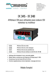
SSI-Anzeige 570
Multifunktions-Geräte mit
SSI Eingang zur Verwendung mit Single- oder
Multiturn-Absolutwertgebern
0.570.012.E90:
Anzeigegerät mit Analogausgang
0.570.011.E00:
Anzeigegerät mit 2 Grenzwertvorgaben und Schaltausgängen
0.570.012.E05:
Anzeigegerät mit seriellen Schnittstellen RS 232 und RS 485
•
•
•
•
Große LED-Anzeige 6 Dekaden (15 mm) mit einstellbarer Helligkeit
Master- oder Slave-Betrieb mit Taktfrequenzen bis 1 MHz
Geeignet für alle SSI-Formate von 8 bis 32 Bit
Zahlreiche Zusatzfunktionen wie Linearisierung, Bitausblendung,
Geberüberwachung usw.
Bedienungsanleitung
0.570.011-012_10a_d.doc / Aug-10
Page 1 / 43
Sicherheitshinweise
• Diese Beschreibung ist wesentlicher Bestandteil des Gerätes und enthält wichtige
Hinweise bezüglich Installation, Funktion und Bedienung.
Nichtbeachtung kann zur Beschädigung oder zur Beeinträchtigung der Sicherheit
von Menschen und Anlagen führen!
• Das Gerät darf nur von einer Elektrofachkraft eingebaut, angeschlossen und in
Betrieb genommen werden
• Es müssen alle allgemeinen sowie länderspezifischen und anwendungsspezifischen
Sicherheitsbestimmungen beachtet werden
• Wird das Gerät in Prozessen eingesetzt, bei denen ein eventuelles Versagen oder
eine Fehlbedienung die Beschädigung der Anlage oder eine Verletzung des
Bedienungspersonals zur Folge haben kann, dann müssen entsprechende
Vorkehrungen zur sicheren Vermeidung solcher Folgen getroffen werden
• Bezüglich Einbausituation, Verdrahtung, Umgebungsbedingungen, Abschirmung und
Erdung von Zuleitung gelten die allgemeinen Standards für den Schaltschrankbau in
der Maschinenindustrie
• - Irrtümer und Änderungen vorbehalten -
Version:
0004/ Wb/sb/ Dez 04
03b/Wb/sb/Feb 08
03c/Wb/sb/Jan.09
07a/Wb/sb/Apr.09
10a/Wb/sb/Juni 10
0.570.011-012_10a_d.doc / Aug-10
Beschreibung:
Bereichserweiterung diverser Parameter auf [-199999, 999999];
Bürde des Analogausgangs erhöht auf max. 300 Ohm
Korrektur Scrollen negativer Werte
Korrektur Dezimalpunkt bei Parameter "Gain"
Funktionserweiterung: Linearisierung, Start einer seriellen Übertragung
Erweiterung 32 Bit, Alarm "Geber fehlt", serielle Sendung extern auslösen
Page 2 / 43
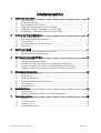
Inhaltsverzeichnis
1.
Elektrische Anschlüsse .................................................................................................. 4
1.1.
1.2.
1.3.
1.4.
1.5.
1.6.
2.
3.
Funktion der Programmiertasten.................................................................................... 8
2.1.
2.2.
2.3.
2.4.
2.5.
Master- und Slave-Betrieb .........................................................................................................26
Bitauswertung ............................................................................................................................27
Skalierung der Anzeige...............................................................................................................28
Grundsätzliche Betriebsarten der Anzeige.................................................................................29
Test-Funktionen ..........................................................................................................................33
Fehlermeldungen ........................................................................................................................33
Sonderfunktionen..........................................................................................................34
6.1.
6.2.
7.
Grundeinstellungen ....................................................................................................................13
Einstellung der Betriebsparameter ............................................................................................15
Zusätzliche Parameter bei Geräten mit Analogausgang (570.012.E90)...................................18
Zusätzliche Parameter bei Geräten mit Grenzwertvorgaben (570.011.E00) .............................20
Zusätzliche Parameter bei Geräten mit serieller Schnittstelle (570.012.E05) .........................22
Hinweise zur Anwendung .............................................................................................26
5.1.
5.2.
5.3.
5.4.
5.5.
5.6.
6.
Übersicht über die Grundparameter (Basismenü)......................................................................11
Übersicht über die Betriebsparameter.......................................................................................12
Die Parametrierung des Gerätes...................................................................................13
4.1.
4.2.
4.3.
4.4.
4.5.
5.
Normaler Anzeigebetrieb .............................................................................................................8
Auswahl und Eingabe von Parametern ........................................................................................9
Teach-Funktion ...........................................................................................................................10
Setzen aller Parameter auf Default-Werte ................................................................................10
Code-Sperre................................................................................................................................10
Das Einstell-Menü ........................................................................................................11
3.1.
3.2.
4.
Stromversorgung ..........................................................................................................................5
Hilfsspannungsausgang ...............................................................................................................5
Steuer-Eingänge Input A, B und C................................................................................................5
Skalierbarer Analogausgang (nur 0.570.012.E90) ......................................................................6
Optokoppler- Transistor- Ausgänge (nur 0.570.011.E00).............................................................6
Serielle RS232 / RS485-Schnittstelle (nur 0.570.012.E05)..........................................................7
Linearisierung .............................................................................................................................34
Manuelle Eingabe oder „Teachen“ der Linearisierungspunkte ................................................36
Technischer Anhang......................................................................................................38
7.1.
7.2.
7.3.
7.4.
Maßbilder ...................................................................................................................................38
Technische Daten .......................................................................................................................39
Parameter-Liste ..........................................................................................................................40
Inbetriebnahmeformular.............................................................................................................42
0.570.011-012_10a_d.doc / Aug-10
Page 3 / 43
0.570.011-012_10a_d.doc / Aug-10
PE
7
GND
0 VAC
0 VAC
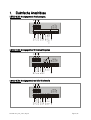
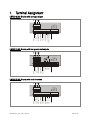
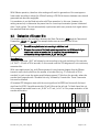
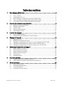
0.570.012.E05: Anzeigegerät mit serieller Schnittstelle
115 VAC
PE
8 9 10
115 VAC
5 6
7
Out 2
PE
0/4-20 mA Analog
+/- 10V Analog
0 VAC
115 VAC
230VAC
Inp. C (Reset)
GND
Inp. A
Inp. B
8
GND Analog
17-30VCD IN
7
Out 1
5 6
Com+
GND
6
GND
5
+24VDC Out
4
+24 VDC Out
3
GND
DAT
DAT
2
TxD / B (-)
4
Inp. C (Reset)
DAT
DAT
1
GND
RxD / A (+)
1 2 3
Inp. B
CLK
CLK
4
+24 VDC Out
4
Inp. A
CLK
CLK
3
GND
DAT
DAT
1 2 3
17-30 VCD In
GND
2
230VAC
4
Inp. C (Reset)
GND
1 2 3
Inp. A (senden)
CLK
CLK
1
230VAC
4
17-30 VCD In
1 2 3
Inp. B
GND
1.
Elektrische Anschlüsse
0.570.012.E90: Anzeigegerät mit Analogausgang
9 10
0.570.011.E00: Anzeigegerät mit 2 Grenzwertvorgaben
8 9 10
Page 4 / 43
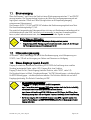
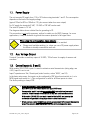
1.1. Stromversorgung
Über die Klemmen 1 und 2 kann das Gerät mit einer Gleichspannung zwischen 17 und 30 VDC
versorgt werden. Die Stromaufnahme hängt von der Höhe der Versorgungsspannung ab und
liegt typisch zwischen 130mA und 190mA (zuzüglich des am Hilfsspannungsausgang
entnommenen Geberstromes).
Die Klemmen 0 VAC, 115 VAC und 230 VAC erlauben die Geräteversorgung direkt vom Netz.
Die Anschlussleistung beträgt 7,5 VA.
Der gestrichelt eingezeichnete Erdungsanschluss ist intern mit Gerätemasse verbunden und ist
sicherheitstechnisch oder EMV- technisch nicht notwendig. In manchen Anwendungsfällen
kann es jedoch wünschenswert sein, das Bezugspotential für die Signale zu erden.
Bitte bei Erdung von GND beachten:
• Es sind damit alle digitalen und analogen Bezugspotentiale geerdet
•
Doppelerdung bei DC- Versorgung sollte vermieden werden, wenn z.B. der Minuspol
der Versorgungsspannung schon extern geerdet ist.
1.2. Hilfsspannungsausgang
An Klemme 7 steht, unabhängig von der Art der Geräteversorgung, eine Hilfsspannung von
24 VDC / max. 120 mA zur Versorgung von Gebern und Sensoren zur Verfügung.
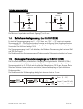
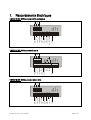
1.3. Steuer-Eingänge Input A, B und C
Eingang A erlaubt bei Geräten der Ausführung 570.012.E05 die Auslösung einer seriellen
Sendung (ansteigende Flanke, siehe 4.5.2). Eingang B ist ohne Funktion.
Eingang C dient als Set / Reset-Eingang (statische Funktion, aktiv "HIGH", siehe 5.3).
Die Eingänge können im Menü „Grundeinstellungen“ für PNP- Betrieb (gegen + schaltend) oder
für NPN- Betrieb (gegen – schaltend) definiert werden. Die Definition bezieht sich auf alle 3
Eingänge gleichzeitig. Die Default- Einstellung ist PNP.
• Bei Einstellung NPN bitte beachten:
Ein offener NPN-Eingang wird stets als HIGH ausgewertet.
Input C muss daher stets extern auf GND gelegt werden, damit das Gerät arbeitsfähig
ist, andernfalls bleibt das Gerät permanent im Reset-Zustand.
Input A muss bei Ausführung 570.012.E05 ebenso auf GND liegen, das Öffnen dieser
Verbindung erzeugt dann eine ansteigende Flanke zur Auslösung der seriellen Sendung
• Bei Verwendung von 2-Draht NAMUR- Sensoren muss NPN angewählt werden. Der
negative Pol des Sensors wird mit GND und der positive Pol mit dem entsprechenden
Eingang verbunden
0.570.011-012_10a_d.doc / Aug-10
Page 5 / 43
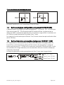
Typische Eingangsschaltung:
PNP
NPN
+24V int.
+24V int.
4,7k
Input
Input
4,7k
GND
GND
GND
Die Minimum- Impulsdauer am Reset- Eingang (C) ist 5 msec.
1.4. Skalierbarer Analogausgang (nur 0.570.012.E90)
Es steht ein Spannungsausgang von 0 … +10 V bzw. von –10 V ... +10 V sowie ein separater
Stromausgang 0/4 – 20 mA proportional zur Anzeige zur Verfügung. Beide Ausgänge beziehen
sich auf GND- Potential. Die Polarität des Ausgangssignals richtet sich nach dem angezeigten
Vorzeichen. Die Auflösung beträgt 14 Bit.
Der Spannungsausgang ist mit 2 mA belastbar, die Bürde am Stromausgang darf zwischen Null
und 300 Ohm liegen.
Die Reaktionszeit des Analogausganges auf Änderungen der Geberposition beträgt ca. 7 msec.
1.5. Optokoppler- Transistor- Ausgänge (nur 0.570.011.E00)
Das Schaltverhalten dieser potentialfreien Ausgänge ist programmierbar. Klemme 8 (COM+)
muss mit dem positiven Pol der zu schaltenden Spannung verbunden werden. Der zulässige
Spannungsbereich ist 5 – 35 Volt und der zulässige Maximalstrom 150 mA pro Ausgang. Beim
Schalten induktiver Lasten wird eine zusätzliche, externe Bedämpfung der Spule durch eine
Diode empfohlen.
Die Reaktionszeit der Schaltausgänge beträgt bei ohmscher Last ca. 5 msec.
Com+ (5 ... 35 V)
Opto
Opto
33 R
33 R
0.570.011-012_10a_d.doc / Aug-10
Output 1 (max. 150 mA)
Output 2 (max. 150 mA)
Page 6 / 43
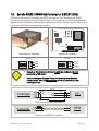
1.6. Serielle RS232 / RS485-Schnittstelle (nur 0.570.012.E05)
Ab Werk ist die serielle Schnittstelle auf RS232 konfiguriert. Eine Umstellung auf RS485
(2-Leiter) ist an einem internen DIL-Schalter möglich. Hierzu müssen die Schraubklemmleisten
abgesteckt und die Rückwand des Gerätes abgenommen werden. Danach kann die Platine nach
hinten aus dem Gehäuse herausgezogen werden.
ON DIP
DIL-Switch
Abnehmen der Rückwand
Lage des DIL-Schalters
RS232:
RS485:
TxD
RxD
GND
10
9
8
ON
ON
B (-)
A (+)
GND
10
9
8
•
Niemals am DIL-Schalter die Schieber 1 und 2 oder die Schieber 3 und 4
gleichzeitig auf ON stellen!
•
Nach Einstellung des Schalters Platine bitte vorsichtig in das Gehäuse
zurückschieben, damit die Übergabestifte zur frontseitigen Tastatur nicht
beschädigt werden.
Schirm
Anzeige
9
10
8
RxD
RxD
2
TxD
TxD
3
GND
5
PC
(Sub-D-9)
Anschluss der RS232-Schnittstelle
Anzeige
9
10
A(+)
A(+)
B(-)
B(-)
SPS
Anschluss der RS485-Schnittstelle
0.570.011-012_10a_d.doc / Aug-10
Page 7 / 43
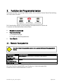
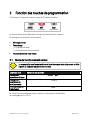
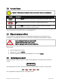
2.
Funktion der Programmiertasten
Das Gerät wird über 3 frontseitige Tasten bedient, die im weiteren Verlauf dieser Beschreibung
wie folgt benannt werden:
ENTER
(Eingabe)
SET
(Einstellung)
Cmd
(Command)
Die Tastenfunktion hängt von dem jeweiligen Betriebszustand des Gerätes ab.
Es werden drei Betriebszustände unterschieden.
•
•
•
Normaler Anzeigebetrieb
Parametrier-Betrieb
a.) Grundeinstellungen
b.) Eingabe von Betriebsparametern
Teach-Betrieb
2.1. Normaler Anzeigebetrieb
Nur vom normalen Anzeigebetrieb aus kann in die anderen Betriebszustände umgeschaltet
werden.
Umschalten zu
Eingabe der
Grundparameter
Eingabe der
Betriebsparameter
Teach-Betrieb
Tastenbedienung
ENTER und SET gleichzeitig 3 Sekunden lang drücken
ENTER 3 Sekunden lang drücken.
Cmd 3 Sekunden lang drücken.
Die Taste Cmd dient ausschließlich zum Teachen von Linearisierungspunkten
Einzelheiten hierzu siehe Abschnitte 6.1 und 6.2.
0.570.011-012_10a_d.doc / Aug-10
Page 8 / 43
2.2. Auswahl und Eingabe von Parametern
2.2.1. Parameter-Auswahl
Die Taste ENTER rollt die einzelnen Menüpunkte durch. Mit der Taste SET wird ein
entsprechender Menüpunkt angewählt, und die gewünschte Auswahl getroffen bzw. der
zugehörige Zahlenwert verändert. Wiederum mit ENTER wird die Auswahl oder der Wert
bestätigt und zum nächsten Menüpunkt weitergeschaltet.
2.2.2. Änderung eines Parameter-Wertes
Bei numerischen Eingaben blinkt zunächst die kleinste Dekade. Durch Dauerbetätigung von
SET kann der Zahlenwert der blinkenden Ziffer verändert werden (rund laufender ScrollDurchgang 0, 1, 2, …...9, 0, 1, 2 usw.). Bei Loslassen von SET bleibt der letzte Wert stehen und
die nächst höherer Ziffer blinkt. So können der Reihe nach alle Dekaden auf den gewünschten
Wert eingestellt werden. Nach Einstellung der höchsten Dekade blinkt wieder die kleinste
Dekade, so dass bei Bedarf noch Korrekturen durchgeführt werden können.
Bei vorzeichenbehafteten Parametern scrollt die höchste Dekade zwischen den Werten
„0“ - "9" (positiv) sowie "-" und "-1" (negativ).
2.2.3. Speichern des Eingabewertes
Zur Speicherung des angezeigten Zahlenwertes wird ENTER betätigt, womit das Gerät
gleichzeitig auf den nächsten Menüpunkt weiterschaltet.
Das Gerät schaltet von der Programmier- Routine in den normalen Anzeigebetrieb zurück, wenn
ENTER mindestens 3 Sekunden lang betätigt wird.
2.2.4. Time-Out-Funktion
Eine „Time-Out“-Funktion sorgt dafür, dass nach einer Betätigungspause von jeweils 10 sec das
Gerät automatisch eine Menüebene höher bzw. zurück in den Betriebszustand springt.
Alle Eingaben, die zu diesem Zeitpunkt noch nicht mit ENTER bestätigt wurden, bleiben
unberücksichtigt.
0.570.011-012_10a_d.doc / Aug-10
Page 9 / 43
2.3. Teach-Funktion
Beim Teachen ist die Time-Out-Funktion abgeschaltet.
Taste
Verwendung
ENTER dient zur Beendigung oder zum Abbruch eines Teach-Vorgangs
SET arbeitet identisch zur normalen Parametrierung
Cmd dient zur Übernahme des momentan angezeigten Wertes in den TeachSpeicher und automatischer Weiterschaltung auf den nächsten Eingabewert
Eine genaue Beschreibung des Teach-Vorgangs erfolgt in Abschnitt 6.2.
2.4. Setzen aller Parameter auf Default-Werte
Sie können jederzeit bei Bedarf sämtliche Parameter des Gerätes auf die ursprünglich
werksseitig eingestellten Default- Werte zurücksetzen. Diese sind aus der nachfolgenden
Parameter-Beschreibung und aus den Parameter-Listen am Ende dieses Dokuments ersichtlich.
Wenn diese Maßnahme durchgeführt wird, gehen sämtliche Parameter und
Einstellungen verloren und das Gerät muss vollständig neu konfiguriert
werden!
Folgende Schritte sind nötig, um das Gerät auf Default-Werte zurückzusetzen:
• das Gerät ausschalten.
• die Taste ENTER drücken.
• Gerät wieder einschalten, während ENTER gedrückt ist
2.5. Code-Sperre
Wenn die Code- Sperre für die Tastatur eingeschaltet ist, erscheint zunächst die Anzeige
Die Tastatur wird in diesem Fall entsperrt, wenn innerhalb von 10 Sekunden die Tastenfolge
eingegeben wird. Ansonsten kehrt das Gerät automatisch zur normalen Anzeige zurück.
0.570.011-012_10a_d.doc / Aug-10
Page 10 / 43
3. Das Einstell-Menü
Das Einstell-Menü besteht aus einem Grundmenü für die Basiswerte des Gerätes und einem
Menü für die Betriebsparameter. Im letzteren Menü erscheinen nur diejenigen
Betriebsparameter, die per Grundmenü auch freigegeben wurden. Wenn z.B. im Grundmenü die
Linearisierungsfunktion ausgeschaltet wurde, dann werden im Parametermenü die
Linearisierungsparameter auch nicht angezeigt.
Die Parameter selbst werden auf der Anzeige so gut wie möglich als Texte dargestellt. Auch
wenn die Möglichkeiten der Text-Darstellung bei einer 7-Segment-Anzeige sehr beschränkt
sind, so hat sich diese Methode doch als intuitives und brauchbares Hilfsmittel zur
Vereinfachung der Programmierung bewährt.
Die nachfolgende Übersicht dient zum allgemeinen Verständnis des Menü-Aufbaus.
Eine genaue Beschreibung der Parameter folgt in Abschnitt 4.
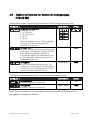
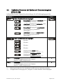
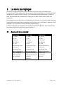
3.1. Übersicht über die Grundparameter (Basismenü)
570.012.E90
570.011.E00
570.012.E05
SSI_Mode
SSI_Mode
SSI_Mode
SSI_Bits
SSI_Bits
SSI_Bits
SSI_Format
SSI_Format
SSI_Format
SSI_Baudrate
SSI_Baudrate
SSI_Baudrate
SSI_Test
Charakertistik
SSI_Test
Charakertistik
SSI_Test
Charakertistik
Helligkeit
Helligkeit
Helligkeit
Code-Sperre
Code-Sperre
Code-Sperre
Linearisierungsmode
Linearisierungsmode
Linearisierungsmode
Aus_Charakteristik
Vorw_Mode 1
Ser_Unit_Nr
Analog Offset
Vorw_Mode 2
Ser_Format
Analog Gain
Hysterese 1
Ser_Baudrate
Hysterese 2
0.570.011-012_10a_d.doc / Aug-10
Page 11 / 43
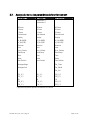
3.2. Übersicht über die Betriebsparameter
570.012.E90
570.011.E00
570.012.E05
Preselection 1
Preselection 2
M-Faktor
D-Faktor
M-Faktor
D-Faktor
M-Faktor
D-Faktor
P-Faktor
P-Faktor
P-Faktor
Dezimalpunkt
Dezimalpunkt
Dezimalpunkt
Display
Hi_Bit (MSB)
Display
Hi_Bit (MSB)
Display
Hi_Bit (MSB)
Lo_Bit (LSB)
Lo_Bit (LSB)
Lo_Bit (LSB)
Direction
Direction
Direction
Error
Error
Error
Error_Polarität
Error_Polarität
Error_Polarität
Round loop
Round loop
Round loop
Time
Time
Time
Reset
Null Position
Reset
Null Position
Reset
Null Position
Analog Beginn
Ser_Timer
Analog Ende
Ser_Mode
Ser_Val
P01_X *)
P01_X *)
P01_X *)
P01_Y*)
Æ
P16_X *)
P16_Y *)
P01_Y*)
Æ
P16_X *)
P16_Y *)
P01_Y*)
Æ
P16_X *)
P16_Y *)
*) erscheint nur, wenn im Grundmenü die Linearisierung eingeschaltet wurde
0.570.011-012_10a_d.doc / Aug-10
Page 12 / 43
4.
Die Parametrierung des Gerätes
Zur besseren Übersicht wird in Abschnitt 4.1 und Abschnitt 4.2 die Parametrierung der reinen
Anzeige beschrieben, wohingegen die modellabhängigen Einstellmöglichkeiten für
Analogausgang, Grenzwertüberwachung oder serieller Schnittstelle später erklärt werden.
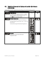
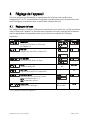
4.1. Grundeinstellungen
Die nachfolgend beschriebenen Einstellungen sind in der Regel einmaliger Art und sind nur bei
der erstmaligen Inbetriebnahme notwendig. Das Grundmenü beinhaltet die Auswahl der
Gerätefunktion, die Eingangsdefinition PNP/ NPN sowie die gewünschte Helligkeit der
Digitalanzeige.
Menüpunkt
Einstellbereich
Default
SSI-Mode:
SSI-Einstellungen Master oder Slave-Mode
Die genaue Beschreibung erfolgt in Abschnitt 5.1
SSI-Bits:
Wortlänge des SSI-Paketes
Die genaue Beschreibung erfolgt in Abschnitt 5.2
.....
SSI-Format:
Einstellung des SSI-Codes (Binär oder Gray)
SSI-Baudrate
SSI_Test:
0.1 - 1000.9
kHz
0 .. 8
100.0 kHz
20%, 40%, 60%
80% und 100%
100%
0
SSI Selbsttest-Funktionen (siehe Abschnitt 5.5.)
Charakertistik: *)
Charakteristik der Steuereingänge
NPN: gegen – schaltend
PNP: gegen + schaltend
Helligkeit:
Helligkeit der Digitalanzeige
*) Bitte Hinweis in Abschnitt 1.3 beachten
0.570.011-012_10a_d.doc / Aug-10
Page 13 / 43
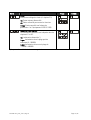
Menüpunkt
Einstellbereich
Default
Code-Sperre:
Zugriffssperre für die Tastatur (siehe Abschnitt 2.5)
no: Tastatur immer frei geschaltet
All: Tastatur für alle Funktionen gesperrt
P-Free: Tastatur gesperrt mit Ausnahme der
Vorwahlwerte Pres 1 und Pres 2 (570.011.E00)
Linearisierungsmode:
Die genaue Beschreibung erfolgt unter 6.1 und 6.2.
no: Die Linearisierung ist ausgeschaltet.*)
1-qua: Die Linearisierung wird nur im ersten
Quadranten (positiver Wertebereich) durchgeführt.
Bei negativen Werten wird die Kurve am Nullpunkt
gespiegelt.
4-qua: Die Linearisierung arbeitet über den
gesamten Bereich.
*) Die Linearisierungs-Parameter erscheinen nicht im Menü
0.570.011-012_10a_d.doc / Aug-10
Page 14 / 43
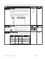
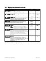
4.2. Einstellung der Betriebsparameter
Menüpunkt
Einstellbereich
Default
-9.999 … 9.999
1.000
D-Factor *):
0.001 … 9.999
1.000
P-Factor *):
-199999
…
999999
0
000000
00000.0
...
0.00000
00000.0
norm
norm
M-Factor *):
Mit diesem Wert wird der SSI-Wert (nach einer
eventuellen Bitausblendung) multipliziert.
Durch diesen Wert wird der SSI-Wert (nach einer
eventuellen Bitausblendung) dividiert.
Dieser vorzeichenbehaftete Wert wird zu dem SSIWert (nach einer eventuellen Bitausblendung)
addiert.
Dezimalpunkt
Einstellung entsprechend den im Display
erscheinenden Formaten.
Display:
Anzeigeart des Gerätes
norm: normale Anzeigenskalierung
359.59: Anzeige im Winkelformat 359° 59' bei
Verwendung der Rundlauf-Funktion
359.59
Hi Bit **):
1 … 32
25
1 … 31
1
Definiert das höchste, auszuwertende Bit (MSB) bei
Benutzung der Bit-Ausblendung. Sollen alle Bits
ausgewertet werden, muss Hi_bit auf die
vorgegebene Gesamtbitzahl eingestellt sein
Lo Bit **):
Definiert das niedrigste, auszuwertende Bit (LSB) bei
Benutzung der Bit-Ausblendung. Sollen alle Bits
ausgewertet werden, muss Lo_bit auf „01“
eingestellt sein.
*) Die Skalierung des Gerätes wird im Abschnitt 5.3 erläutert.
**) Die genaue Beschreibung der Bitausblendung erfolgt im Abschnitt 5.2
0.570.011-012_10a_d.doc / Aug-10
Page 15 / 43
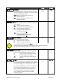
Menüpunkt
Direction
Erlaubt die Negierung des SSI-Wertes, was wie eine
Umkehrung der Drehrichtung des Gebers wirkt.
riGht: steigende Werte bei Vorwärtsbewegung
LEFt:: fallende Werte bei Vorwärtsbewegung
Error (siehe auch Abschnitt 5.6)
Einstellbereich
Default
riGht
LEFt
riGht
0 ... 32
0
0
1
0
Definiert die Geberüberwachung und das Error-Bit
00: kein Error-Bit vorhanden
Überprüfung auf angeschlossenen Geber Aus
01: - kein Error-Bit vorhanden
- Geberüberwachung- Ein
- Überprüfung auf angeschlossenen Geber Ein
>01: Position des auszuwertenden Error-Bits
- Geberüberwachung - Ein
- Überprüfung auf angeschlossenen Geber Ein
Error-Polarität *):
Definiert die Polarität des Error Bits im Fehlerfall.
0: Bit ist Low im Fehlerfall
1: Bit ist High im Fehlerfall
Im Fehlerfall erscheint auf der Anzeige „Err-b“.
Mit dieser Funktion kann auch das Spannungsüberwachungsbit
(bei vielen Geberherstellern als „PFB“ bezeichnet) ausgewertet werden.
Round Loop:
0 ... 999999
0
0.000 .. 1.009
sec
0.01 sec
Definiert die Anzahl der Geberschritte, wenn eine
Rundlauf-Funktion gewünscht wird.
(siehe Abschnitt 5.4.2).
0:
>0:
Normale Anzeige der Geberdaten, Rundlauf
ist ausgeschaltet
Schrittzahl für die Rundlauf-Funktion
Time:
Bestimmt den Einlesezyklus und damit auch die
Auffrischungszeit der Anzeige sowie ggf. des
Analogausganges und der Schaltausgänge. Der
schnellstmögliche Zyklus ist 3 msec. bzw. eine
Telegrammlänge incl. 4 Pausentakte. Im SlaveBetrieb erfolgt die nächste Einlesung, wenn sich das
Gerät nach Ablauf der Zykluszeit auf die nächste
Pause des Masters aufsynchronisiert.
0.570.011-012_10a_d.doc / Aug-10
Page 16 / 43
Menüpunkt
Einstellbereich
Default
-199999
...
999999
0
-199999
... 999999
-199999
... 999999
999999
Reset:
Ein Reset speichert den momentanen Positionswert
automatisch unter dem Parameter „Null Position“ ab.
Damit wird die Anzeige an der momentanen Position
auf Null gesetzt und alle anderen Positionen
orientieren sich an diesem Nullpunkt. Die
Nullposition bleibt auch im stromlosen Zustand
erhalten.
no:
Front:
E_tErn:
FR u E:
Reset-Funktion gesperrt
Reset über die frontseitige Taste SET
Reset über externen Reset-Eingang
Reset über Taste und Reset-Eingang
Null Position: *)
Definiert die Nullposition der Anzeige. Wird „0-Pos“
z.B. auf 1024 gesetzt, dann zeigt das Gerät bei der
tatsächlichen Geberposition 1024 den Wert Null an.
„0-Pos“ kann entweder direkt als Zahlenwert
vorgegeben oder mittels eines Reset-Signals
automatisch gesetzt werden.
P01_X **)
Linearisierungspunkt 1:
X-Koordinate des 1. Linearisierungspunktes.
P01_Y
Linearisierungspunkt 1:
Y-Koordinate des 1. Linearisierungspunktes.
999999
…
Linearisierungspunkt 16:
-199999
999999
... 999999
X-Koordinate des 16. Linearisierungspunktes.
-199999
999999
P16_Y
Linearisierungspunkt 16:
...
999999
Y-Koordinate des 16. Linearisierungspunktes.
*) Bitte beachten, dass Parameter "P_Fac" ggfs. eine zusätzliche Verschiebung der Nullposition bewirkt
**) Die Parameter P01_X bis P16_Y erscheinen nur bei eingeschalteter Linearisierung
P16_X
0.570.011-012_10a_d.doc / Aug-10
Page 17 / 43
4.3. Zusätzliche Parameter bei Geräten mit Analogausgang
(570.012.E90)
Im Basis-Menü werden folgende Grundeinstellungen für den Analogausgang getroffen:
Menüpunkt
Einstellbereich
Default
-9,999..+9,999
0,000
00,00..99,99
10,00
Ausgangs-Charakteristik:
Wählen Sie zwischen
+/- 10 V (bipolar),
0 - 10 V (nur positiv),
4 - 20 mA
0 - 20 mA.
Wenn das Ausgangsformat (+/- 10Volt) angewählt
wird, folgt die Polarität des Ausgangs dem
Vorzeichen in der Anzeige.
Analog Offset:
Stellen Sie den Wert auf 0, wenn ihr Analogausgang
bei Null (bzw. 4 mA) beginnen soll. Wenn Sie einen
anderen Nullpunkt wünschen, ist dieser hier
einzugeben (Eingabe von z.B. 5.000 bedeutet, dass
der Analogausgang im Nullzustand bereits 5 Volt
Ausgangsspannung liefert).
Analog Gain:
Stellen Sie hier den gewünschten Hub ein. Eine
Einstellung von 10.00 entspricht einem Bereich von
10 Volt bzw. 20 mA, eine Einstellung von z.B. 8.00
reduziert den Hub auf 8 Volt bzw. 16 mA.
Die folgenden Betriebsparameter dienen zur Skalierung des Analogausgangs:
Menüpunkt
Einstellbereich
Default
Analog-Beginn:
-199999...999999
0
Analog-Ende:
-199999...999999
100000
Startwert der analogen Aussteuerung .
Endwert der analogen Aussteuerung .
Diese Parameter erlauben es, einen beliebigen Ausschnitt des gesamten Messbereiches auf
den gewählten Analogbereich abbilden.
0.570.011-012_10a_d.doc / Aug-10
Page 18 / 43
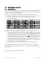
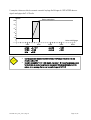
Das nachstehende Beispiel zeigt, wie ein Anzeigebereich von 1400 bis 2000 in ein analoges
Signal von 2 - 10 Volt umgewandelt wird.
Volt
Analogausgang
10
8
6
4
2
SSI-Anzeigewert
1000
A-ChAr = 0 - 10 V
OFFSEt = 2.000
GAin
= 8.00
2000
3000
AnAbEG
AnAEnd
4000
5000
= 1400
= 2000
•
Die Vorgaben für den Wandlungsbereich beziehen sich auf den in der Anzeige
erscheinenden Wert, nicht auf die Originaldaten des SSI-Gebers.
•
Bei eingeschalteter Geberüberwachung (Parameter "Error" ≥ 01) wird bei
fehlendem Gebersignal oder nicht angeschlossenem Geber der Analogausgang mit
"0" ausgesteuert und eine entsprechende Error-Meldung angezeigt
(siehe auch Abschnitt 5.6)
0.570.011-012_10a_d.doc / Aug-10
Page 19 / 43
4.4.
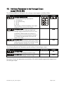
Zusätzliche Parameter bei Geräten mit Grenzwertvorgaben
(570.011.E00)
Im Basis-Menü werden folgende Grundeinstellungen für die Schaltausgänge getroffen:
Menüpunkt
Default
Schalt-Charakteristik des Ausgangs 1.
Greater/Equal. Ausgang wird statisch aktiv, wenn
Anzeigewert ≥ Vorwahlwert
Lower/Equal. Ausgang wird statisch aktiv, wenn
Anzeigewert ≤ Vorwahlwert.
Greater/Equal. Ausgang wird dynamisch aktiv,
wenn Anzeigewert ≥ Vorwahlwert
(Wischimpuls *)
Lower/Equal. Ausgang wird dynamisch aktiv,
wenn Anzeigewert ≤ Vorwahlwert
(Wischimpuls *)
Schalt-Charakteristik des Ausgangs 2.
Wie oben
Wie oben
Wie oben
Wie oben
Ausgang schaltet statisch, wenn
Anzeigewert ≥ Vorwahl 1 – Vorwahl 2 **)
Ausgang schaltet dynamisch, wenn
Anzeigewert ≥ Vorwahl 1 – Vorwahl 2 **)
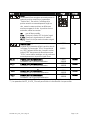
HYSt 1
Hysterese 1
0
HYSt 2
Hysterese 2
0
Einstellbare Schalthysterese für den Ausgang 1
Bereich 0 .. 99999 Anzeigeeinheiten
Einstellbare Schalthysterese für den Ausgang 2
Bereich 0 .. 99999 Anzeigeeinheiten
*)
**)
Wischimpulse haben eine feste Impulsdauer von 500 msec (nur werksseitig verstellbar)
Schleppvorwahl zur Erzeugung eines „Vorsignals“ in festem Abstand zu einem Hauptsignal
0.570.011-012_10a_d.doc / Aug-10
Page 20 / 43
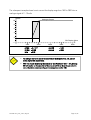
Die folgenden Betriebsparameter dienen zur Vorgabe der Grenzwerte:
Menüpunkt
Einstellbereich
Default
Vorwahlwert 1:
-199999 ... 999999
10000
Vorwahlwert 2:
-199999 ... 999999
5000
Die Arbeitsrichtung der Schalthysterese hängt von der Vorgabe der Schaltcharakteristik ab.
Entsprechend der Einstellung „GE“ oder „LE“ ergeben sich folgende Schaltpunkte:
Messwert
Vorwahlwert
Hysterese
GE=Greater/Equal
Schaltverhalten bei Einstellung "Greater / Equal"
Hysterese
Vorwahlwert
Messwert
LE=Lower/Equal
Schaltverhalten bei Einstellung "Lower / Equal"
Der Schaltzustand der beiden Ausgänge kann jederzeit abgefragt werden.
Hierzu kurz die ENTER-Taste antippen.
Das Display zeigt dann für ca. 2 sec eine der folgenden Informationen
Anzeige
Bedeutung
Beide Ausgänge sind ausgeschaltet.
Beide Ausgänge sind eingeschaltet.
Ausgang 1 ist eingeschaltet.
Ausgang 2 ist ausgeschaltet.
Ausgang 1 ist ausgeschaltet.
Ausgang 2 ist eingeschaltet.
•
Bei eingeschalteter Geberüberwachung (Parameter "Error" ≥ 01) wird bei
fehlendem Gebersignal oder nicht angeschlossenem Geber der Anzeigewert mit "0"
ausgegeben und eine entsprechende Error-Meldung angezeigt
(siehe auch Abschnitt 5.6). Evtl. aktive Ausgänge werden hierbei inaktiv geschaltet
0.570.011-012_10a_d.doc / Aug-10
Page 21 / 43
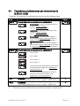
4.5. Zusätzliche Parameter bei Geräten mit serieller Schnittstelle
(570.012.E05)
Im Basis-Menü werden folgende Grundeinstellungen für die Schnittstelle getroffen:
Menüpunkt
Geräte-Adresse:
Einstellbereich
Default
0..99
11
Den Geräten können Adressen zwischen 11 und 99
zugeordnet werden. Adressen die eine “0“ enthalten
sind nicht erlaubt, da diese als Gruppen- bzw.
Sammeladressen verwendet werden.
Serielles Datenformat:
Das erste Zeichen gibt die Anzahl der Datenbits an.
Das zweite Zeichen steht für Parity „Even“, "Odd“ oder
kein Parity-Bit.
Das dritte Zeichen gibt die Anzahl der Stopp-Bits an.
Baudrate:
Es können die nebenstehenden Baudraten
ausgewählt werden.
0.570.011-012_10a_d.doc / Aug-10
Page 22 / 43
Die folgenden Betriebsparameter dienen zur Konfiguration der Schnittstelle:
Menüpunkt
Serieller Timer:
Bei Einstellung 0,000 kann eine serielle Übertragung
manuell ausgelöst werden. Die anderen Einstellungen
dienen zur Einstellung der Zykluszeit für den seriellen
Printer-Mode.
Einstellbereich
Default
0,000
0,100 sec
0,010 sec
…
9.999 sec
Zwischen zwei Sendungen wird automatisch eine von der
Baudrate abhängige minimale Zykluszeit eingehalten.
Baudrate
Minimale Zykluszeit [ms]
600
384
1200
192
2400
96
4800
48
9600
24
19200
12
38400
6
Serieller Mode:
PC:
Print1:
Print2:
Schnittstelle arbeitet gemäß
Kommunikationsprofil (siehe 4.5.1)
Senden von String Type 1 (siehe 4.5.2)
Senden von String Type 2 (siehe 4.5.2)
Serieller Register-Code:
Spezifiziert die Codestelle des Parameters, dessen Daten
ausgelesen werden sollen. Die wichtigsten Codestellen für
eine serielle Auslesung sind:
Register
Original SSIWert
SSI-Wert
S-Code
111
ASCII
;1
113
;3
Anzeigewert
(SSI-Istwert)
101
:1
0.570.011-012_10a_d.doc / Aug-10
100
...
120
101
Beschreibung
Eingelesener
SSI-Wert
SSI-Wert nach BitAusblendung
Skalierter
Anzeigewert
Page 23 / 43
4.5.1. PC-Mode
Im PC-Mode können beliebige Register direkt via serielle Schnittstelle ausgelesen werden. Das
folgende Beispiel zeigt den Ablauf der Kommunikation zur Abfrage des aktuellen
Anzeigewertes.
Der Abfragestring allgemein hat das
nebenstehend gezeigte Format:
EOT
AD1 AD2 C1 C2 ENQ
EOT = Steuerzeichen (Hex 04)
AD1 = Geräteadresse, High Byte
AD2 = Geräteadresse, Low Byte
C1 = auszulesende Codestelle, High Byte
C2 = auszulesende Codestelle, Low Byte
ENQ = Steuerzeichen (Hex 05)
Beispiel: Anfrage des aktuellen Anzeigewertes bei einem Gerät mit der seriellen Adresse 11:
ASCII-Code:
EOT
Hexadezimal:
04
Binär:
0000 0100
1
31
0011 0001
Bei korrekter Anfrage antwortet das
Gerät wie nebenstehend. Vornullen
werden nicht übertragen. BCC ist ein
„Block-Check-Character“, der sich durch
ein Exclusiv-Oder aller Zeichen zwischen
einschließlich C1 und ETX ergibt.
1
31
0011 0001
:
3A
0011 1010
1
31
0011 0001
ENQ
05
0000 0101
STX C1 C2 x x x x x x x ETX BCC
STX = Steuerzeichen (Hex 02)
C1 = auszulesende Codestelle, High Byte
C2 = auszulesende Codestelle, Low Byte
x x x x x = auszulesende Daten
ETX = Steuerzeichen (Hex 03)
BCC = Block check character
Bei fehlerhaftem Anfragestring antwortet das Gerät nur mit STX C1 C2 EOT oder mit NAK.
0.570.011-012_10a_d.doc / Aug-10
Page 24 / 43
4.5.2. Printer-Mode
Der Printer-Mode ermöglicht die zyklische oder manuelle Auslösung der Übertragung eines
Registerwertes. Das Register wird mittels des Parameters „S-Code“ spezifiziert.
Parameter „S-mod“ erlaubt die Auswahl zwischen zwei verschiedenen Sendestrings.
„S-mod“
„Print1“
Sendestring
Leerzeichen Vorzeichen Daten
+/-
„Print2“
X
X
X
X
X
X
Vorzeichen Daten
+/-
X
X
X
X
X
X
Line
feed
LF
Carriage
return
CR
Carriage
return
CR
Die Art der Auslösung wird wie folgt angewählt:
Zyklische Auslösung
Manuelle Auslösung
Seriellen Timer auf einen Wert ≥ 10 einstellen.
Mit "S-mod" den Sendestring auswählen.
Nach dem Verlassen des Einstellmenüs wird das zyklische Versenden
automatisch gestartet.
Seriellen Timer auf Null einstellen.
Mit "S-mod" den Sendestring auswählen.
Nach dem Verlassen des Einstellmenüs kann jederzeit manuell eine
Übertragung ausgelöst werden, und zwar
- durch kurze Betätigung der Enter-Taste oder
- durch eine ansteigende Flanke an Input A
Bei eingeschalteter Geberüberwachung (Parameter "Error" ≥ 01) wird bei fehlendem
Gebersignal oder nicht angeschlossenem Geber der Anzeigewert mit "0" ausgegeben
und eine entsprechende Error-Meldung angezeigt (siehe auch Abschnitt 5.6).
0.570.011-012_10a_d.doc / Aug-10
Page 25 / 43
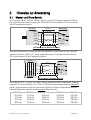
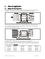
5.
Hinweise zur Anwendung
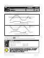
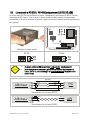
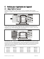
5.1. Master- und Slave-Betrieb
Der Parameter „Mode“ wird auf „Master“ gesetzt, wenn die SSI-Anzeige selbst den Takt für
den angeschlossenen Geber erzeugen soll. Die beiden Clock-Anschlüsse (CLK) sind in diesem
Fall als Ausgänge konfiguriert.
SSI-Geber
(+24V)
Schirm
SSI-Anzeige
(optional)
7 (+24V out)
Clock-
CLK
Clock+
CLK
DataData+
DAT
GND
6 (GND)
DAT
SSI-Anzeige im Master-Betrieb
Wird der Geber bereits von einem anderen Gerät getaktet, und das Gerät soll nur „mithören“,
muss der Parameter „Mode“ auf „Slave“ eingestellt werden. Die beiden Clock-Anschlüsse
(CLK) sind in diesem Fall als Eingänge konfiguriert.
SSI-Anzeige
Master
Schirm
Clock-
CLK
CLK
Clock+
Data-
DAT
DAT
Clock-
Data+
Data-
+
Clock+
Data+
6 (GND)
-
SSI-Geber
SSI-Anzeige im Slave-Betrieb
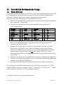
Die Parameter „Bits“, „Format“ und „Baud“ werden entsprechend dem eingesetzten Gebertyp
eingestellt. Es kann im Bereich von 0,1 kHz bis 1000,0 kHz jede beliebige Baudrate eingestellt
werden, jedoch kann das Gerät aus technischen Gründen im oberen Frequenzbereich nur die
folgenden Baudraten tatsächlich exakt erzeugen (Masterbetrieb):
1000,0 kHz
615,0 kHz
444,0 kHz
347,0 kHz
285,0 kHz
888,0 kHz
571,0 kHz
421,0 kHz
333,0 kHz
275,0 kHz
0.570.011-012_10a_d.doc / Aug-10
800,0 kHz
533,0 kHz
400,0 kHz
320,0 kHz
266,0 kHz
727,0 kHz
500,0 kHz
380,0 kHz
307,0 kHz
258,0 kHz
666,0 kHz
470,0 kHz
363,0 kHz
296,0 kHz
250,0 kHz
Page 26 / 43
Im Master-Betrieb wird daher bei Vorgabe anderer Werte entweder der nächst höhere oder der
nächst niedrigere Wert aus obiger Liste erzeugt. Bei Vorgaben < 250,0 kHz werden die
Abweichungen zwischen eingestellter und erzeugter Baudrate vernachlässigbar klein.
Auch im Slave-Betrieb muss die Baudrate vorgegeben werden. Die Vorgabe dient hier jedoch
nur zur Bestimmung der Pausenzeit für die Aufsynchronisierung (Pause wird erkannt nach 4
Taktzyklen). Das Gerät synchronisiert sich automatisch auf jedes externe Taktsignal innerhalb
des spezifizierten Baud-Bereiches auf.
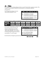
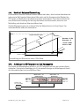
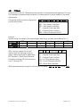
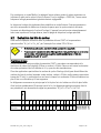
5.2. Bitauswertung
Dieser Abschnitt erklärt den Zusammenhang zwischen dem Basisparameter „BitS“ und den
Betriebsparametern „Hi bit“ und „Lo bit“ am Beispiel eines SSI-Gebers mit 16 Bit
•
Nicht benötigte Bits können nach Belieben ausgeblendet werden.
•
Immer wenn die vom Master angeforderte Bitzahl nicht identisch zur tatsächlichen
Bitzahl des Gebers ist, muss eine Ausblendung der Überschuss-Bits mit Hilfe der
Parameter „Hi bit“ und „Lo bit“ vorgenommen werden,
Grundeinstellungen:
In aller Regel wird der Basisparameter „BitS“ entsprechend der tatsächlichen Auflösung des
verwendeten Gebers eingestellt (also 16 bei einem 16-Bit-Geber). In diesem Fall ist jedes
übertragene Bit ein gültiges Bit und das Telegramm enthält keine überschüssigen Bits.
In einigen Fällen (z.B. bei Slave-Betrieb) kann jedoch die angefragte Bitzahl des Masters auch
höher als die tatsächliche Auflösung des Gebers sein (z.B. 21 Bits). Der Master fordert in
diesem angenommenen Fall vom Geber immer 21 Bits an. Der Geber hingegen liefert aber nur
16 verwertbare Bits zurück, die restlichen Bits sind überschüssig und müssen ausgeblendet
werden.
Ein SSI-Telegramm beginnt grundsätzlich mit dem höchsten Bit und endet mit dem kleinsten
Bit. Die überzähligen, nicht nutzbaren Bits (X) kommen ganz zum Schluss. Zur Auswertung der
16 verwendbaren Bits muss daher in dem angenommenen Beispiel „Hi bit“ auf 21 und „Lo bit“
auf 6 eingestellt werden.
Lo Bit Î
Hi Bit Î
Angeforderte
Bits (Master)
21
20 19 18 17 16 15 14 13 12 11 10 9
8
7
6
5
4
3
2
1
Verwendbare
Bits (Geber)
16
15 14 13 12 11 10 9
3
2
1
X
X
X
X
X
0.570.011-012_10a_d.doc / Aug-10
8
7
6
5
4
Page 27 / 43
5.3. Skalierung der Anzeige
Unter Berücksichtigung der zuvor beschriebenen Parameter ergibt sich der angezeigte Wert aus
Anzeige
=
{ [SSI-Wert des Gebers]
- [0-Position] } x
M-Factor
D-Factor
+/- P-Factor
• Die von einem SSI-Geber übertragenen Werte sind stets nur positiv. Wenn das Gerät
auch negative Werte anzeigen soll, kann dies ausschließlich durch entsprechende
Einstellung der Parameter „0-Position“ oder „P-Factor“ erreicht werden
• Die Anzeige des Gerätes verfügt über 6 Dekaden. Aus diesem Grunde haben alle
Parameter maximal 6 Stellen, so auch der Parameter „0-Position“. Wenn Sie nun
einen Geber mit mehr als 19 Bit benutzen, kann dieser auch Werte mit mehr als 6
Stellen erzeugen. Je nach mechanischer Stellung des Gebers kann es dann schwierig
werden, Nullpunkt und Skalierung richtig einzustellen, solange sich der Geber in der
Überlaufzone befindet (das Gerät könnte hartnäckig „Überlauf“ anzeigen). Um dieses
Problem zu vermeiden, empfehlen wir daher, bei Gebern mit höherer Auflösung stets
die Bit-Blanking-Funktion zu benutzen und nur maximal 19 Bits auszuwerten
(bei einem 25-Bit-Geber also z.B. Hi_Bit = 19 und Lo-Bit = 01)
• Falls die später beschriebene „Round-Loop-Funktion“ benutzt werden soll, ist eine
entsprechende Bit-Ausblendung sogar zwingend erforderlich.
• Ein Reset/Set-Signal über die Tastatur oder den externen Eingang überschreibt den
Parameter „0-Position“ mit der aktuellen SSI-Position des Gebers. Damit wird in
obiger Formel der Inhalt der Klammer { } auf Null gesetzt, d.h. das Gerät zeigt nun
den unter Parameter „P-Factor“ eingegebenen Setzwert an. Der neue Wert des
Parameters „0-Position“ bleibt auch nach Ausschalten der Geräteversorgung
erhalten.
0.570.011-012_10a_d.doc / Aug-10
Page 28 / 43
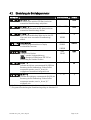
5.4. Grundsätzliche Betriebsarten der Anzeige
5.4.1. Normale SSI-Anzeige
Im Normalbetrieb wird der eingelesene SSI-Wert mit den Skalierungsparametern bewertet und
zur Anzeige gebracht. Durch die Verschiebung der Null-Position und durch Änderung des
Parameters „Direction“ können auch negative Anzeigewerte erzeugt werden.
Bei der Einstellung des Gerätes gehen Sie am Besten wie folgt vor:
• Führen Sie die grundsätzlichen Einstellungen entsprechend des verwendeten Gebertyps
durch, wie unter 4.1 beschrieben.
• Geben Sie zur besseren Übersicht zunächst folgende Anfangsparameter ein
(xxx = wie gewünscht):
M-Factor
D-Factor
P-Factor
Decimal Point
Display
Hi bit
Lo bit
:
:
:
:
:
:
:
1.000
1.000
0
000000
0
siehe 5.2 *)
siehe 5.2 *)
Direction
Error
Error P
Round-Loop
Time
Reset
0-Position
:
:
:
:
:
:
:
0
xxx
xxx
0
xxx
no
0
*) Bitte zur Vermeidung von Überlauf nur maximal 19 Bit auswerten
Hiermit ist zunächst gewährleistet, dass das Gerät unverfälscht die direkte SSIInformation des Gebers anzeigt.
• Bewegen Sie nun den Geber von einer nach Ihrer Definition „kleineren“ Position in
Richtung einer „größeren“ Position. Wenn die Anzeige nun ebenso von kleineren
Werten nach größeren Werten ansteigt, stimmt Ihre Richtungsdefinition mit der des
Gebers überein. Ansonsten ändern Sie jetzt den Parameter „Direction“, um die
Zählrichtung Ihrem Wunsch anzupassen (spätere Änderung kann andere Ergebnisse zur
Folge haben). **)
• Definieren Sie nun den von Ihnen gewünschten Nullpunkt, entweder durch Eingabe der
0-Position oder über ein Reset-Signal, wie zuvor beschrieben. Unterhalb der Nullposition
erhalten Sie nun negative Anzeigewerte.
• Jetzt können Sie alle anderen Parameter entsprechend Ihren Wünschen anpassen.
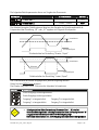
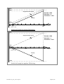
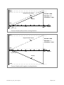
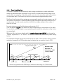
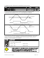
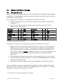
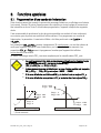
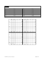
Die nachfolgenden Schaubilder zeigen das Verhalten der Anzeige am Beispiel eines 13-BitSingleturn-Gebers, wobei der Parameter „Direction“ einmal auf „0“ und einmal auf „1“ gesetzt
und der Parameter „0-Position“ mit 1024 vorgegeben wurde.**)
**)Richtige Reihenfolge der Programmierung vorausgesetzt
0.570.011-012_10a_d.doc / Aug-10
Page 29 / 43
8192
7168
Original encoder signal
Encoder 13Bit
Direction = 0
0-Position = 1024
Display
1024
0o
45 o
180o
degrees
360 o
0-PoS = 1024
Verlauf der Anzeige bei positiver Zählrichtung
8192
Original encoder signal
Encoder 13Bit
Direction = 1
0-Position = 1024
1024
0o
45 o
0-PoS = 1024
360 o
180o
degrees
Display
-7168
Verlauf der Anzeige bei negativer Zählrichtung
0.570.011-012_10a_d.doc / Aug-10
Page 30 / 43
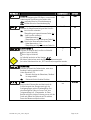
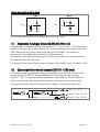
5.4.2. Rundlaufbetrieb
Diese Betriebsart wird häufig verwendet bei Rundtischen oder ähnlichen Anwendungen, wo die
absolute Geberinformation nur innerhalb einer Tischumdrehung benötigt wird, wobei einer
Tischumdrehung nicht unbedingt auch eine Geberumdrehung zugeordnet sein muss.
Negative Anzeigen gibt es im Rundlaufbetrieb nicht.
Die Rundlauffunktion gestattet die beliebige Abbildung einer Tischumdrehung auf eine
programmierbare Anzahl von Geberschritten. Um Fehlanzeigen am mechanischen Überlaufpunkt
des Gebers zu vermeiden, sollte allerdings die Gesamtzahl der Geberschritte ein ganzzahliges
Vielfaches der Schrittanzahl für eine Tischumdrehung darstellen.
Zur Einstellung des Gerätes verfahren Sie bitte zunächst wie unter 5.4.1. beschrieben.
Dann stellen Sie den Parameter „r-LooP“ auf die gewünschte Schrittzahl pro Tischumdrehung
ein. Die Anzeige kann mittels der Skalierungsfaktoren auf beliebige Anzeigeeinheiten
eingestellt werden.
Sofern Sie ein Anzeigeformat 359º59’ wünschen, setzen Sie den Parameter „Display“ zusätzlich
auf „359,59“. In diesem Falle werden die allgemeinen Skalierungsfaktoren automatisch
deaktiviert.
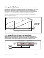
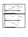
Das nachfolgende Diagramm zeigt einen 13-Bit-Absolutgeber, bei dem eine Tischumdrehung
2048 Geberschritten entspricht und der Nullpunkt bei 1024 Geberschritten liegt.
8192
Original encoder signal
Encoder 13Bit
Direction = 0
0-Position = 1024
r-Loop = 2048
Round-Loop display
2048
1024
180
0
0-PoS = 1024
360 degrees
r-LooP = 2048
Rundlaufbetrieb mit 2048 Schritten / Umdrehung bei Verwendung eines 13-Bit-Gebers
0.570.011-012_10a_d.doc / Aug-10
Page 31 / 43
5.4.3. Betrieb mit Nullpunkts-Überschreitung
Ein besonderer Vorteil der Rundlauf-Funktion besteht auch darin, dass bei dieser Betriebsart die
mechanische Null-Lage des Gebers keine Rolle spielt, weil die Anzeige auch bei Überlauf des
SSI-Signals von Maximalwert auf Null kontinuierlich weiterarbeitet. Somit kann bei Bedarf auf
eine mechanische Justierung der Null-Lage des Gebers verzichtet werden, wenn sich eine
Nullstellung nicht direkt am Geber durchführen lässt.
Zweckmäßigerweise setzt man in diesem Falle den Nullpunkt durch ein Reset-Signal. Das
nachstehende Bild erklärt die Arbeitsweise.
8192
Original encoder signal
Overflow
Encoder: 13 Bit
Direction = 0
r-LooP = 6000
Display
0-PoS = 3500
3500
0o
360 o
0-PoS = 3500
degrees
r-LooP = 6000
Unterdrückung des Überlaufs bei einem 13-Bit-Geber
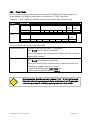
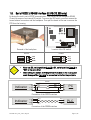
5.4.4. Aufteilung eines SSI-Telegramms auf zwei Anzeigegeräte
Die Funktion der Bitausblendung erlaubt es, ein SSI-Telegramm auf zwei oder mehrere Geräte
aufzuteilen. Eine typische Anwendung ist z.B. die separate Anzeige von Winkellage und Anzahl
der Achsumdrehungen bei einem Multiturn-Geber.
Master: Bit 17 - 32
(Umdrehungen)
Multiturn SSI
16 + 16 = 32 Bit
0.570.011-012_10a_d.doc / Aug-10
Parameter:
Bits = 32
HiBit = 32
LoBit = 17
Slave: Bit 01 - 16
(Winkellage)
Parameter:
Bits = 32
HiBit = 16
LoBit = 01
Page 32 / 43
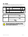
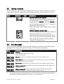
5.5. Test-Funktionen
In das Testmenü gelangt man bei den Grundeinstellungen, wie unter Abschnitt 4.1 beschrieben.
Die meisten Tests dienen der werksseitigen Prüfung, die folgenden Tests können aber auch für
den Anwender hilfreich sein:
Menü
Auswahl
Text
Beschreibung
Cd (Clock- und Daten-Leitungstest):
Wenn die Verdrahtung der Clock- und der
Datenleitungen in Ordnung ist, erscheint „Cd 11“ im
Display.
„Cd 10“ bedeutet, dass die Datenleitung nicht korrekt
arbeitet oder vertauscht ist.
"CD 01" zeigt ein Problem mit der Clock-Leitung an. Im
Master-Mode wird nur die Datenleitung getestet.
Cd (Clock- und Daten-Funktionstest):
Bei diesem Test generiert das Gerät selbst Clock und
Daten und speist diese über die eigenen Klemmen
wieder ein. Deshalb sollte der Datenstecker entfernt
sein.
„Cd iO“ bedeutet „Clock und Daten in Ordnung, während
alle anderen Anzeigen auf einen Fehler an der SSISchnittstelle hindeuten.
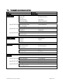
5.6. Fehlermeldungen
Die folgenden Fehler werden vom Gerät erkannt und als Fehlermeldung angezeigt.
In allen genannten Fällen sollten Sie die Datenleitungen und die Parametrierung des Gerätes
nochmals genau überprüfen:
Menü
Beschreibung
Overflow:
Die gewählte Baudrate ist zu hoch. Bitte kleinere Baudrate einstellen
Error-Bit:
Das Error-Bit oder das Spannungsüberwachungsbit (PFB) des Gebers ist gesetzt.
Error-time-out: im Slave-Betrieb ist während der letzten 0,6 Sekunden (zuzüglich
programmierter Wartezeit) kein Telegramm mehr angekommen.
Error-Format: die Länge eines im Slave-Betrieb übertragenen Telegramms ist zu kurz.
Geber fehlt (1*): unmittelbar nach dem Einschalten des Gerätes wird festgestellt, dass
die SSI-Telegramme leer sind (sämtliche Bits = 1).
Geber fehlt (2*): während des Betriebes wird festgestellt, dass nach zunächst
regulären SSI-Telegrammen nur noch Leer-Telegramme folgen (sämtliche Bits = 1).
*)
Der Anzeigewert wird auf 0 gestellt, der Analogausgang oder die Grenzwerte werden deaktiviert
(nur bei eingeschalteter Geberüberwachung „Error > 0“ siehe 4.2)
0.570.011-012_10a_d.doc / Aug-10
Page 33 / 43
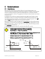
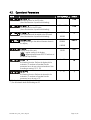
6. Sonderfunktionen
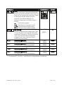
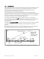
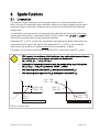
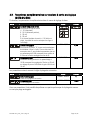
6.1. Linearisierung
Mit Hilfe dieser Funktion kann auf einfache Weise ein lineares Eingangssignal in eine
nichtlineare Darstellung umgewandelt werden (oder umgekehrt). Es stehen 16 LinearisierungsPunkte zur Verfügung, die über den gesamten Wandlungsbereich in beliebigen Abständen
verteilt werden können. Zwischen 2 vorgegebenen Koordinaten findet automatisch eine lineare
Interpolation statt.
Es empfiehlt sich, an Stellen mit starker Kurvenkrümmung möglichst viele Punkte zu setzen,
wohingegen an Stellen mit schwacher Krümmung nur wenige Punkte ausreichend sind. Um
eine Linearisierungskurve vorzugeben, muss der Parameter „Linearisierungsmode“ auf 1-quA
oder auf 4-quA eingestellt werden (siehe nachstehendes Schaubild).
Mit den Parametern P01_X bis P16_X geben Sie 16 x- Koordinaten vor. Das sind die normalen
Anzeigewerte, die das Gerät ohne Linearisierung in Abhängigkeit des Eingangssignals erzeugt.
Mit den Parametern P01_Y bis P16_Y geben Sie nun vor, welchen Wert die Anzeige an dieser
Stelle stattdessen annehmen soll.
Es wird also zum Beispiel der Wert P02_x wird durch den Wert P02_y ersetzt.
•
Aus Konsistenzgründen müssen die x- Register mit kontinuierlich
ansteigenden Werten belegt werden, d.h. es muss die Bedingung
P01_X < P02_X < … < P15_X < P16_X erfüllt sein.
•
Unabhängig vom Linearisierungsmode ist der vom Gerät akzeptierte Eingabebereich für die
Punkte P01_X, P01_Y,…, P16_X, P16_Y immer -199999 … 999999.
•
Bei Messwerten kleiner als P01_X zeigt das Gerät konstant P01_Y an.
•
Bei Messwerten größer als P16_X zeigt das Gerät konstant P16_Y an.
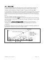
y
P1(x)= -1000
P1(y)= 900
P16(x)= 1000
P16(y)= 800
x
*)
P1(x)= 0
P1(y)= 0
Linearisation Mode = 1_quA
y
P8(x)= 0
P8(y)= 750
x
P16(x)= +1000
P16(y)= - 600
Linearisation Mode = 4_quA
*) Kurve verläuft punktsymmetrisch zum 1. Quadranten
0.570.011-012_10a_d.doc / Aug-10
Page 34 / 43
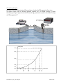
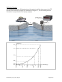
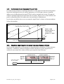
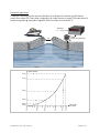
Anwendungsbeispiel:
Das untenstehende Bild zeigt eine Wasserschleuse, bei der die Öffnungsweite über einen
SSI-Geber erfasst und zur Anzeige gebracht werden soll. Der Geber erzeugt in dieser
Anordnung ein Signal proportional zum Drehwinkel φ, gewünscht ist jedoch die direkte Anzeige
der Öffnungsweite "d"
Anzeigewert
d = d0 (1-cos φ )
SSI-Geber
d
φ
Anzeigewert
P16_y
P15_y
P07_y
P05_y
0.570.011-012_10a_d.doc / Aug-10
P16_x
P15_x
P07_x
P05_x
SSI-Wert
P03_x
P01_x
P03_y
P01_y
Page 35 / 43
6.2. Manuelle Eingabe oder „Teachen“ der Linearisierungspunkte
Die Punkte zur Bildung einer Linearisierungskurve können wie alle Parameter mit dem normalen
Tastatur-Dialog vorgegeben werden. In diesem Falle werden alle Werte P01_x bis P16_x und
die zugeordneten Ersatzwerte P01_y bis P16_y einzeln eingegeben.
Der Benutzer muss bei manueller Eingabe die Konsistenz der Werte P01_x bis P16_x
gewährleisten ( P01_X < P02_X < … < P15_X < P16_X )
Eine Überwachung durch das Gerät erfolgt nicht.
In den meisten Fällen ist es aber praktischer, die eingebaute „Teach“-Funktion zu benutzen.
Hierbei bewegt man den SSI-Geber schrittweise auf die gewünschten Stützpunkte und gibt per
Tastatur den jeweils dazugehörigen Anzeigewert vor.
So benutzen Sie die eingebaute Teach-Funktion zur Vorgabe einer Linearisierungskurve:
• Bitte wählen Sie unter den Basis-Parametern den gewünschten Linearisierungsmode
aus (siehe auch Abschnitt 4.1).
• Halten Sie die Taste „Cmd“ für 3 Sekunden gedrückt. Auf dem Display erscheint die
Anzeige „tEACh“. Um den Teach-Vorgang zu beginnen, drücken Sie bitte innerhalb der
nächsten 10 Sekunden nochmals kurz die Taste „Cmd“.
Auf der Anzeige erscheint nun „P01_X“.
• Aus Konsistenzgründen werden automatisch alle Linearisierungspunkte zunächst mit
Startwerten überschrieben. Die Startwerte sind für „P01_X“ und „P01_Y“ gleich
-199999. Alle anderen Stützpunkte haben den Startwert 999999.
• Betätigen Sie nochmals „Cmd“, um den momentan vom Geber gelieferten Istwert
anzuzeigen. Sorgen Sie nun dafür, dass die Position des SSI-Gebers dem ersten
Linearisierungs-Stützpunkt entspricht.
• Sobald Sie in der Anzeige den X-Wert des ersten Linearisierungspunktes sehen, drücken
Sie erneut die „Cmd“-Taste. Der momentane Anzeigewert wird als „P01_X“
abgespeichert und für ca. 1 Sekunde zeigt das Display „P01_Y“. Danach wird wieder der
gespeicherte P01_X-Wert angezeigt.
• Diesen X-Wert können Sie nun wie bei einer normalen Parameter-Eingabe beliebig
verändern, um daraus den gewünschten Y-Wert zu bilden.
• Nachdem der gewünschte P01_Y-Wert eingestellt ist, wird dieser durch erneute
Betätigung von „Cmd“ gespeichert, und das Gerät schaltet auf den nächsten Stützpunkt
P02_x weiter.
0.570.011-012_10a_d.doc / Aug-10
Page 36 / 43
• Wenn Sie den letzten Punkt P16_x programmiert haben, beginnt die Routine erneut
beim ersten Stützpunkt P01_X. Sie haben damit Gelegenheit, die Eingaben nochmals zu
kontrollieren und bei Bedarf nochmals zu korrigieren.
• Beenden Sie den Teach-Vorgang, indem Sie für 2 Sekunden die Taste „ENTER“ drücken.
Das Display zeigt dann für 2 Sekunden „StoP“ und kehrt zur normalen Anzeige-Betrieb
zurück. Die Linearisierungs-Stützpunkte sind nun gespeichert.
• Das Gerät überwacht die Konsistenzbedingung. Die x-Koordinate des neuen Stützpunktes
muss größer als der vorherige Wert sein. Sollte dieses nicht zutreffen, dann leuchten am
unteren Rand des Displays 6 Punkte als Warnsignal auf. Eine Übernahme des inkorrekten
Stützpunktes mittels Cmd-Taste ist nicht möglich. Bei der Betätigung der Cmd-Taste wird
stattdessen der Fehlertext "E.r.r.-.L.O." ausgegeben.
• Sie haben jederzeit die Möglichkeit, den Teach-Vorgang auf eine der folgenden beiden
Arten abzubrechen:
1. Drücken Sie für 2 Sekunden die Enter-Taste. Auf dem Display erscheint für etwa 1 sec
„Stop“. Danach schaltet das Gerät in den Normalbetrieb zurück.
2. Tun Sie einfach gar nichts. Nach etwa 10 Sekunden schaltet das Gerät automatisch in
den Normalbetrieb zurück.
In beiden Fällen werden die Linearisierungsparameter P01_x bis P16_y nicht geändert.
0.570.011-012_10a_d.doc / Aug-10
Page 37 / 43
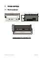
7.
Technischer Anhang
7.1. Maßbilder
110,0 (4.331’’)
91,0 (3.583)
48,0 (1.890)
10,0
(.394)
44,0 (1.732)
8,0
(.315)
96,0 (3.780’’)
9,0 (.345)
129,0 (5.079)
140,5 (5.531)
Schalttafel-Ausschnitt: 91 x 44 mm (3.583 x 1.732’’)
0.570.011-012_10a_d.doc / Aug-10
Page 38 / 43
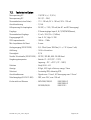
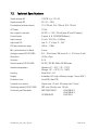
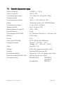
7.2. Technische Daten
Nennspannung AC
: 115/230 V (+/- 12,5 %)
Nennspannung DC
: 24 V (17 – 30 V)
Stromaufnahme (ohne Geber)
: 17 V : 190 mA, 24 V : 150 mA, 30 V : 120 mA
Anschlussleistung
: 7,5 VA
Hilfsspannung für Impulsgeber
: 24 VDC, +/- 15%, 120 mA (bei AC- und DC-Versorgung)
Eingänge
: 3 Steuereingänge Input A, B, C (PNP/NPN/Namur),
Stromaufnahme Eingänge
: 5,1 mA / 24 V (Ri = 4,7 kOhm)
Eingangspegel HTL
: Low: 0...2V, High: 9...35V
SSI-Frequenzbereich
: 100 Hz – 1 MHz
Min. Impulsdauer für Reset
: 5 msec
Analogausgang (570.012.E90)
: 0/4...20 mA (max. 300 Ohm), 0...+/- 10 V (max. 2 mA)
Auflösung
: 14 Bit + Vorzeichen
Genauigkeit
: 0,1%
Serielle Schnittstelle (570.012.E05) : RS 232 / RS 485, 600 - 38 400 Baud
Umgebungstemperatur
: Betrieb: 0° - 45°C (32° - 113°F)
Lagerung: -25° - +70°C (-13° - 158°F)
Gehäuse
: Norly UL94 – V-0
Anzeige
: 6 Digit, LED, high- efficiency orange, 15mm
Schutzart
: Frontseitig IP65, rückseitig IP20
Anschlussklemmen
: Signale max. 1.5 mm², AC-Versorgung max. 2.5 mm²
Schaltausgänge (0.570.011.E00)
: PNP, max. 35 V, max. 150 mA
Konformität und Normen
: EMV 2004/108/EG:
NS 2006/95/EG:
0.570.011-012_10a_d.doc / Aug-10
EN 61000-6-2
EN 61000-6-3
EN 61010-1
Page 39 / 43
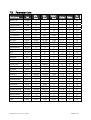
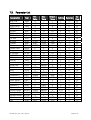
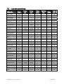
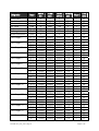
7.3. Parameter-Liste
Bezeichnung
NPN / PNP
Helligkeit
Tastatursperre
SSI-Mode
SSI-Bits
SSI-Gray/Bin
SSI-Baudrate
Test
M-Faktor
D-Faktor
PM-Faktor
Dezimalpunkt
Display
MSB
LSB
Direction
Error Bit
Error Polarität
Round Loop
Wait Time
FE Reset
SSI-Null Position
Vorwahl 1
Vorwahl 2
Vorwahlmode 1
Vorwahlmode 2
Hysterese 1
Hysterese 2
Analog Anfangs
Analog Endwert
Analog Mode
Offset
Gain
Text
CHAr
briGht
Code
modE
bitS
Form
bAUd
tESt
mFAc
dFAc
PFAc
dPoint
diSPLA
Hi_bit
Lo_bit
dir
Error
ErrorP
r-looP
timE
FErES
0-PoS
PrES 1
PrES 2
CHAr 1
CHAr 2
Hyst1
Hyst2
An-bEG
An-End
A-CHAr
OFFSEt
GAin
0.570.011-012_10a_d.doc / Aug-10
Min Wert
0
0
0
0
08
0
0.1
0
-9.999
0.001
-199999
0
0
1
1
0
0
0
0
0.000
0
-199999
-199999
-199999
0
0
0
0
-199999
-199999
0
-9,999
00,00
Max Wert
1
4
2
1
32
1
1000.9
8
+9.999
9.999
+999999
5
1
32
31
1
32
1
999999
1.009
3
+999999
+999999
+999999
3
5
99999
99999
999999
999999
3
+9,999
99,99
Default Wert
1
0
0
0
25
0
100.0
0
1.000
1.000
0
0
0
25
1
0
0
0
0
0.010
0
0
10000
5000
0
0
0
0
0
100000
0
0,000
10,00
Stellen Zeichen
1
1
1
1
2
1
5
1
+/- 4
4
+/- 6
1
1
2
2
1
2
1
6
4
1
+/- 6
+/- 6
+/- 6
1
1
5
5
+/- 6
+/- 6
1
+/- 4
4
0
0
0
0
0
0
1
0
3
3
0
0
0
0
0
0
0
0
0
3
0
0
0
0
0
0
0
0
0
0
0
3
2
Ser.
Code
05
06
07
00
01
02
03
04
08
09
10
11
12
13
14
15
16
17
18
19
20
21
27
28
29
30
36
37
31
32
33
34
35
Page 40 / 43
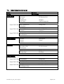
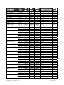
Bezeichnung
Ser. Format
Baudrate
Ser. Adresse
Ser. Timer
Ser. Betriebsart
Register-Code
Linearisierungsmode
Linear.Punkt 1
Linear.Punkt 2
Linear.Punkt 3
Linear.Punkt 4
Linear.Punkt 5
Linear.Punkt 6
Linear.Punkt 7
Linear.Punkt 8
Linear.Punkt 9
Linear.Punkt 10
Linear.Punkt 11
Linear.Punkt 12
Linear.Punkt 13
Linear.Punkt 14
Linear.Punkt 15
Linear.Punkt 16
Text
S-Form
S-bAUd
S-Unit
S-tim
S-mod
S-CodE
LinEAr
P01_H
P01_Y
P02_H
P02_Y
P03_H
P03_Y
P04_H
P04_Y
P05_H
P05_Y
P06_H
P06_Y
P07_H
P07_Y
P08_H
P08_Y
P09_H
P09_Y
P10_H
P10_Y
P11_H
P11_Y
P12_H
P12_Y
P13_H
P13_Y
P14_H
P14_Y
P15_H
P15_Y
P16_H
P16_Y
0.570.011-012_10a_d.doc / Aug-10
Min Wert
0
0
0
10
0
100
0
-199999
-199999
-199999
-199999
-199999
-199999
-199999
-199999
-199999
-199999
-199999
-199999
-199999
-199999
-199999
-199999
-199999
-199999
-199999
-199999
-199999
-199999
-199999
-199999
-199999
-199999
-199999
-199999
-199999
-199999
-199999
-199999
Max Wert
9
6
99
9999
2
120
2
999999
999999
999999
999999
999999
999999
999999
999999
999999
999999
999999
999999
999999
999999
999999
999999
999999
999999
999999
999999
999999
999999
999999
999999
999999
999999
999999
999999
999999
999999
999999
999999
Default Wert
0
0
11
100
0
101
0
999999
999999
999999
999999
999999
999999
999999
999999
999999
999999
999999
999999
999999
999999
999999
999999
999999
999999
999999
999999
999999
999999
999999
999999
999999
999999
999999
999999
999999
999999
999999
999999
Stellen Zeichen
1
1
2
4
1
3
1
+/-6
+/-6
+/-6
+/-6
+/-6
+/-6
+/-6
+/-6
+/-6
+/-6
+/-6
+/-6
+/-6
+/-6
+/-6
+/-6
+/-6
+/-6
+/-6
+/-6
+/-6
+/-6
+/-6
+/-6
+/-6
+/-6
+/-6
+/-6
+/-6
+/-6
+/-6
+/-6
0
0
0
3
0
0
0
0
0
0
0
0
0
0
0
0
0
0
0
0
0
0
0
0
0
0
0
0
0
0
0
0
0
0
0
0
0
0
0
Ser.
Code
92
91
90
38
39
40
D2
A0
A1
A2
A3
A4
A5
A6
A7
A8
A9
B0
B1
B2
B3
B4
B5
B6
B7
B8
B9
C0
C1
C2
C3
C4
C5
C6
C7
C8
C9
D0
D1
Page 41 / 43
7.4. Inbetriebnahmeformular
Datum:
Operator:
General Setting:
Software:
Seriennummer:
SSI-Mode:
SSI-Format:
SSI-Test:
Charakteristik:
Code Sperre:
SSI-Bits:
SSI-Baudrate (kHz):
Helligkeit:
Linearisierungsmode:
Zusatz 570.012.E90 Ausg_Charakteristik:
Analog Gain:
Analog Offset:
Zusatz 570.011.E00 Vorwahl-Mode 1
Hysteresis 1
Vorwahl-Mode 2:
Hysteresis 2:
Zusatz 570.012.E05 Serial Unit Nr:
Serial Baudrate:
Serial Format:
Display-Parameter
M-Factor:
D-Factor:
P-Factor:
Decimalpoint:
Display:
SSI-Spezial:
SSI-Highbit: (MSB):
SSI-Lowbit: (LSB):
SSI-Direction:
SSI-Errorbit:
SSI-E-Bit Polarität:
SSI-Round Loop:
SSI-Gap Time:
SSI-Reset Function:
SSI-Offset:
Zusatz-Parameter:
Zusatz 570.012.E90 Analog-Beginn:
Analog-Ende:
Zusatz 570.011.E00 Vorwahlwert 1:
Vorwahlwert 2:
Zusatz 570.012.E05 Serial Timer:
Serial Register Code:
Serial Printer Mode:
0.570.011-012_10a_d.doc / Aug-10
Page 42 / 43
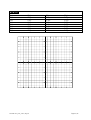
Linearisierung
P1(x):
P2(x):
P3(x):
P4(x):
P5(x):
P6(x):
P7(x):
P8(x):
P1(y):
P2(y):
P3(y):
P4(y):
P5(y):
P6(y):
P7(y):
P8(y):
0.570.011-012_10a_d.doc / Aug-10
P9(x):
P10(x):
P11(x):
P12(x):
P13(x):
P14(x):
P15(x):
P16(x):
P9(y):
P10(y):
P11(y):
P12(y):
P13(y):
P14(y):
P15(y):
P16(y):
Page 43 / 43
Fritz Kübler GmbH
Zähl- und Sensortechnik
Postfach 34 40
D-78023 Villingen-Schwenningen
Tel.: 07720-3903-0
Fax: 07720-21564
www.kuebler.com
SSI Indicator 570
Universal Display Units with
SSI Input for use with Single Turn or Multi Turn
Absolute Encoders
0.570.012.E90:
Display unit with analogue output
0.570.011.E00:
Display unit with two presets and outputs
0.570.012.E05:
Display unit with serial interface RS323 and 485
•
•
•
•
Clear LED display (15 mm / 0.59’’ size) with adjustable brightness
Master- or Slave operation at Baud rates up to 1 MHz
Suitable for all SSI formats from 8 to 32 bits
Supplementary functions like linearization, bit blanking, encoder monitoring
and more
Operating Instructions
0.570.011-012_10a_e.doc / Aug-10
Page 1 / 43
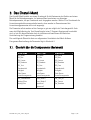
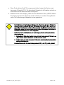
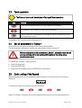
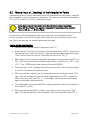
Safety Instructions
• This manual is an essential part of the unit and contains important hints about
function, correct handling and commissioning. Non-observance can result in
damage to the unit or the machine or even in injury to persons using the
equipment!
• The unit must only be installed, connected and activated by a qualified electrician
• It is a must to observe all general and also all country-specific and applicationspecific safety standards
• When this unit is used with applications where failure or maloperation could cause
damage to a machine or hazard to the operating staff, it is indispensable to meet
effective precautions in order to avoid such consequences
• Regarding installation, wiring, environmental conditions, screening of cables and
earthing, you must follow the general standards of industrial automation industry
• - Errors and omissions excepted –
Version:
0004/ Wb/sb/ Dec 04
03b/WB/sb/ Feb 08
03c/WB/sb/ Jan 09
07a/WB/sb/ Apr 09
10a/WB/sb/ June 10
Description:
Range of PM-Factor, SSI zero position and preselection mode
1 / 2 increase to [-199999, 999999];
load on the current output max. 300 Ohm
Correction: scrolling to negative settings
Correction: decimal point with parameter "Gain"
Extensions: Linearization, Activation of serial transmission
Extension 32 bits, missing encoder alarm, remote start of serial string
0.570.011-012_10a_e.doc / Aug-10
Page 2 / 43
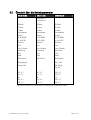
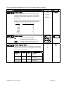
Table of Contents
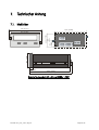
1.
Terminal Assignment ..................................................................................................... 4
1.1.
1.2.
1.3.
1.4.
1.5.
1.6.
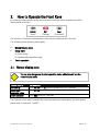
2.
How to Operate the Front Keys...................................................................................... 8
2.1.
2.2.
2.3.
2.4.
2.5.
3.
Master and Slave Operation ......................................................................................................26
Evaluation of Encoder Bits .........................................................................................................27
Scaling of the Display.................................................................................................................28
Basic Modes of Operation..........................................................................................................29
Testing Functions........................................................................................................................33
Error Messages...........................................................................................................................33
Special Functions ..........................................................................................................34
6.1.
6.2.
7.
Basic Parameters........................................................................................................................13
Operational Parameters..............................................................................................................15
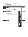
Additional Parameters for the Analogue Output (model 570.012.E90).....................................18
Additional Parameters for Preselections and Switching Outputs (model 570.011.E00)..........20
Additional Parameters for Units with Serial Interface (model 570.012.E05)...........................22
Hints for Application .....................................................................................................26
5.1.
5.2.
5.3.
5.4.
5.5.
5.6.
6.
Overview of Basic Parameters ...................................................................................................11
Overview of Operational Parameters.........................................................................................12
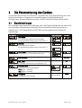
Setup Procedure............................................................................................................13
4.1.
4.2.
4.3.
4.4.
4.5.
5.
Normal display state ....................................................................................................................8
Selection and Setting of Parameters ...........................................................................................9
Teach operation..........................................................................................................................10
Set all parameters to “Default“ .................................................................................................10
Code Locking of the Keypad .......................................................................................................10
The Operator Menu.......................................................................................................11
3.1.
3.2.
4.
Power Supply................................................................................................................................5
Aux. Voltage Output .....................................................................................................................5
Control Inputs A, B and C .............................................................................................................5
Adjustable Analogue Output (0.570.012.E90 only)......................................................................6
Optocoupler (transistor) outputs (0.570.011.E00 only) ................................................................6
Serial RS232 / RS485 interface (0.570.012.E05 only) .................................................................7
Linearization ...............................................................................................................................34
Manual Input or „Teaching“ of the Interpolation Points ...........................................................36
Technical Appendix.......................................................................................................38
7.1.
7.2.
7.3.
7.4.
Dimensions .................................................................................................................................38
Technical Specifications.............................................................................................................39
Parameter-List ............................................................................................................................40
Commissioning Form ..................................................................................................................42
0.570.011-012_10a_e.doc / Aug-10
Page 3 / 43
0.570.011-012_10a_e.doc / Aug-10
DAT
1 2
3
4
5
Input B
Input C (Reset)
GND
DAT
CLK
4
2
3
4
5
6
7
8
9 10
GND
17-30 VCD IN
Input A
Input B
Input C (Reset)
GND
0.570.012.E05: Display with serial interface
8
9 10
6
7
8
9 10
115 VAC
5
0 VAC
4
0 VAC
3
115 VAC
2
GND
17-30 VCD IN
Input A
Input B
Input C (Reset)
GND
+24 VDC OUT
GND analogue
+/- 10 V analogue
GND
1
PE
0 VAC
115 VAC
230VAC
DAT
4
230VAC
DAT
3
230VAC
CLK
2
0/4-20 mA analogue
CLK
1
PE
TxD / B (-)
PE
7
OUT 2
6
GND
RxD / A (+)
GND
1
OUT 1
4
COM+
DAT
3
+24 VDC OUT
DAT
2
GND
CLK
CLK
1
+24 VDC OUT
CLK
3
Input A (transm.)
GND
1 2
17-30 VCD IN
1.
Terminal Assignment
0.570.012.E90: Display with analogue output
0.570.011.E00: Display with two presets and outputs
Page 4 / 43
1.1. Power Supply
The unit accepts DC supply from 17 V to 30 V when using terminals 1 and 2. The consumption
depends on the level of the supply voltage
(typical 130mA at 30V or 190mA at 17V, plus current taken from aux. output).
For AC supply the terminals 0 VAC, 115 VAC or 230 VAC can be used.
The total AC power is 7.5 VA.
The diagrams below show a dotted line for grounding to PE.
This connection is not really necessary, neither for safety nor for EMC. However, for some
applications, it may be desirable to ground the common potential of all signal lines.
When using this earthing option, please observe:
• All terminals and potentials marked “GND“ will be earthed.
• Please avoid multiple earthing, i.e. when you use a DC power supply where
the Minus is already connected to earth etc.
1.2. Aux. Voltage Output
Terminal 7 provides an auxiliary output of 24 VDC / 120 mA max. for supply of sensors and
encoders.
1.3. Control Inputs A, B and C
With models 570.012.E05, input A is used to activate a serial transmission (rising edge, see
4.5.2). Input B is not in use.
Input C operates as a Set / Reset input (static function, active "HIGH", see 5.3).
In the basic setup menu, the inputs can be configured to PNP (signal must switch to +) or to
NPN (signal must switch to -). This configuration is valid for all three inputs at a time.
The factory setting is always PNP.
• Where NPN setting is used, please observe:
Open NPN inputs will always represent a logical HIGH state
Consequently, Input C has to be connected to GND externally to allow normal
operation. If unconnected, the unit would be kept in a continuous Reset state.
With models 570.012.E05, also Input A must be tied to GND, and opening this
connection will generate a rising edge to start a serial transmission
• Where your use 2-wire NAMUR type sensors, please select NPN, connect the negative
wire of the sensor to GND and the positive wire to the corresponding input.
0.570.011-012_10a_e.doc / Aug-10
Page 5 / 43
Typical input circuit of control input
PNP
NPN
+24V int.
+24V int.
4,7k
Input
Input
4,7k
GND
GND
GND
The minimum pulse duration on the Reset input (C) must be 5 msec.
1.4. Adjustable Analogue Output (0.570.012.E90 only)
A voltage output is available, operating in a range of 0 ... +10 V or –10 V ... +10 V according to
setting. At the same time, a current output 0/4 – 20 mA is available. Both outputs refer to the
GND potential and the polarity changes with the sign in the display. The outputs are
proportional to the display value and provide a 14 bits resolution.
The maximum current on the voltage output is 2 mA, and the load on the current output can
vary between 0 and max. 300 ohms.
The response time of the analogue output to changes of the encoder position is approx. 7 msec.
1.5. Optocoupler (transistor) outputs (0.570.011.E00 only)
The outputs provide programmable switching characteristics and are potential-free. Please
connect terminal 8 (COM+) to the positive potential of the voltage you like to switch
(range 5V....35V). You must not exceed the maximum output current of 150 mA. Where you
switch inductive loads, please provide filtering of the coil by means of an external diode.
The optocoupler outputs provide a response time of approx. 5 msec with resistive load.
Com+ (5 ... 35 V)
Opto
Opto
33 R
33 R
0.570.011-012_10a_e.doc / Aug-10
Output 1 (max. 150 mA)
Output 2 (max. 150 mA)
Page 6 / 43
1.6. Serial RS232 / RS485 interface (0.570.012.E05 only)
Ex factory the unit is set to RS232 communication. This setting can be changed to RS485
(2-wire) by means of an internal DIL switch. To access the DIL switch, you must remove the
screw terminal connectors and the backplane. Then pull the board to the rear to remove the
PCB from the housing.
ON DIP
DIL-Switch
Removal of the back plane
Location of the DIL switch
RS232:
RS485:
TxD
RxD
GND
10
9
8
ON
•
•
ON
B (-)
A (+)
GND
10
9
8
Never set DIL switch positions 1 and 2 or DIL switch positions 3 and 4 to
“ON” at the same time!
After setting the switch, shift the print carefully back to the housing and
avoid damage of the front pins for connection to the front keypad plate.
Screen
9
10
8
Indicator
RxD
RxD
2
TxD
TxD
3
GND
5
PC
(Sub-D-9)
Connection of the RS232 interface
Indicator
9
10
A(+)
A(+)
B(-)
B(-)
PLC
Connection of the RS485 interface
0.570.011-012_10a_e.doc / Aug-10
Page 7 / 43
2.
How to Operate the Front Keys
For setup and other operations the unit uses three front keys which subsequently will be
denominated as follows:
ENTER
(Input)
SET
(Setting)
Cmd
(Command)
The functions of the keys are depending on the actual operating state of the unit.
The following three operating states apply:
•
•
•
Normal display state
Setup state
a.) Basic setup
b.) Operational parameter setup
Teach operation
2.1. Normal display state
You can only change over to other operation states while the unit is in the
normal display state.
Change over to
Basic setup
Operational
parameter setup
Teach operation
Key operation
Keep ENTER and SET down simultaneously for 3 seconds
Keep ENTER down for 3 seconds.
Keep Cmd down for 3 seconds
The Cmd key is only used to execute the Teach procedure with linearization. For more details
please refer to sections 6.1 and 6.2.
0.570.011-012_10a_e.doc / Aug-10
Page 8 / 43
2.2. Selection and Setting of Parameters
2.2.1. How to select a parameter
The ENTER key will scroll through the menu. The SET key allows to select the corresponding
item and to change the setting or the numeric value. After this, the selection can be stored by
ENTER again, which automatically changes over to the next menu item.
2.2.2. How to change parameter settings
With numerical entries, at first the lowest digit will blink. When keeping the SET key
continuously down, the highlighted digit will scroll in a continuous loop from 0 … 9 , 0 … 9.
After releasing the SET key, the actual value will remain and the next digit will be highlighted
(blink). This procedure allows setting of all digits to the desired values. After the most
significant digit has been set, the low order digit will blink again and you can do corrections if
necessary.
With signed parameters, the high order digit will scroll from “0” to "9" (positive) followed by
“-“ and "-1" (negative)
2.2.3. How to store settings
To store the actual setting, press the ENTER key, which will also automatically scroll forward
the menu.
At any time the unit changes from programming mode to normal display operation, when you
keep the ENTER key down again for at least 3 seconds.
2.2.4. Time-out function
A “time-out” function will automatically conclude every menu level, when for a break period of
10 seconds no key has been touched. In this case, any changes which have not been confirmed
by ENTER yet would remain unconsidered.
0.570.011-012_10a_e.doc / Aug-10
Page 9 / 43
2.3. Teach operation
The Time-out function will be switched off during all Teach operations
Key
Function
ENTER will conclude or abort any Teach operation in progress
SET function is fully similar to normal set-up operation
Cmd will store the display value to the register and will change over to the
next interpolation point.
For details of the Teach procedure see section 6.2.
2.4. Set all parameters to “Default“
At any time you can return all settings to the factory default values.
The factory default settings are shown in the parameter listings in section 6.
When you decide to set all parameters to „default“, please be aware that all
previous settings will be lost and you will need to do the whole set-up
procedure once more
To execute the „Default“ setting function:
• Power the unit down.
• Press the ENTER key.
• Power the unit up again while the ENTER key is kept down
2.5. Code Locking of the Keypad
When the code locking of the keypad has been switched on, any key access first results in
display of
To access the menu you must press the key sequence
within 10 seconds, otherwise the unit will automatically return to the normal display mode.
0.570.011-012_10a_e.doc / Aug-10
Page 10 / 43
3.
The Operator Menu
The menu provides one section with “Basic Parameters” and another section with “Operational
Parameters”. On the display you will only find those parameters which have been enabled by
the basic settings. E.g. when the Linearisation Functions have been disabled in the basic setup, the associated linearization parameters will also not appear in the parameter menu.
All parameters, as good as possible, are designated by text fragments. Even though the
possibilities of forming texts are very limited with a 7-segment display, this method has proved
to be most suitable for simplification of the programming procedure.
The subsequent table shows the general structure of the whole menu only.
Detailed descriptions of all parameters will follow in section 4.
3.1. Overview of Basic Parameters
570.012.E90
570.011.E00
570.012.E05
SSI_Mode
SSI_Mode
SSI_Mode
SSI_Bits
SSI_Bits
SSI_Bits
SSI_Format
SSI_Format
SSI_Format
SSI_Baud Rate
SSI_Test
SSI_Baud Rate
SSI_Test
SSI_Baud Rate
SSI_Test
Characteristics
Characteristics
Characteristics
Brightness
Brightness
Brightness
Code Locking
Linearization Mode
Code Locking
Linearization Mode
Code Locking
Linearization Mode
Analogue Characteristics
Preselection_Mode 1
Ser_Unit_Nr
Analogue Offset
Preselection_Mode 2
Ser_Format
Analogue Gain
Hysteresis 1
Ser_Baudrate
Hysteresis 2
0.570.011-012_10a_e.doc / Aug-10
Page 11 / 43
3.2. Overview of Operational Parameters
570.012.E90
570.011.E00
570.012.E05
Preselection 1
Preselection 2
M-Factor
M-Factor
M-Factor
D-Factor
D-Factor
D-Factor
P-Factor
Decimal point
P-Factor
Decimal point
P-Factor
Decimal point
Display
Display
Display
Hi_Bit (MSB)
Hi_Bit (MSB)
Hi_Bit (MSB)
Lo_Bit (LSB)
Direction
Lo_Bit (LSB)
Direction
Lo_Bit (LSB)
Direction
Error
Error
Error
Error_Polarity
Error_Polarity
Error_Polarity
Round Loop
Time
Round Loop
Time
Round Loop
Time
Reset
Reset
Reset
Zero Position
Zero Position
Zero Position
Analogue Begin
Analogue End
Ser_Timer
Ser_Mode
Ser_Value
P01_X *)
P01_Y*)
Æ
P16_X *)
P01_X *)
P01_Y*)
Æ
P16_X *)
P01_X *)
P01_Y*)
Æ
P16_X *)
P16_Y *)
P16_Y *)
P16_Y *)
*) appears only when Linearization has been enabled in the Basic Menu
0.570.011-012_10a_e.doc / Aug-10
Page 12 / 43
4.
Setup Procedure
For better understanding the following sections 4.1 and 4.2 explain settings for the display only.
Model-specific settings for Analogue Output, Preselections and Serial Link will be explained
separately, later.
4.1. Basic Parameters
The subsequent settings are of unique nature and must only be made upon the very first setup.
The basic setup selects the desired operation mode of the unit, the input characteristics
PNP/NPN and the desired brightness of the LED display.
Menu
Setting Range
Default
SSI-Mode
Setting of Master Mode or Slave Mode
For details see section 5.1
SSI-Bits
Bit length of the SSI string
For details see section 5.2
.....
SSI-Format:
Setting of the SSI code (Binary or Gray)
SSI-Baud Rate
SSI Test
0.1 ... 1000.9
kHz
0 ... 8
100.0
kHz
0
20%, 40%, 60%
80% and 100%
100%
SSI Self test functions (see 5.5.)
Characteristics *)
Switching characteristics of the control inputs
NPN: switch to "-"
PNP: switch to "+"
Brightness
Brightness of the 7-segment LED display
*) Please observe hints given in chapter 1.3
0.570.011-012_10a_e.doc / Aug-10
Page 13 / 43
Menu
Setting Range
Default
Code Locking
Interlock of keypad access (see 2.5)
no: Keypad accessible at any time
All: Keypad interlock for all functions
P-Free: Keypad interlock except for Preselection
Settings Pres 1 und Pres 2 (model 570.011.E00)
Linearization Mode
For details please see 6.1 und 6.2.
no: Linearization is switched OFF *)
1-qua: Linearization settings for the positive range
only (negative values will appear as a mirror).
4-qua: Linearization over the full numeric range
*) The menu will not display any further linearization parameters
0.570.011-012_10a_e.doc / Aug-10
Page 14 / 43
4.2. Operational Parameters
Menu
Setting Range
Default
-9.999 … 9.999
1.000
0.001 … 9.999
1.000
P-Factor *):
-199999
…
999999
0
Decimal Point
000000
00000.0
...
0.00000
00000.0
norm
norm
M-Factor *):
Multiplying factor for the SSI value
(after consideration of possible bit blanking)
D-Factor *):
Dividing factor for the SSI value
(after consideration of possible bit blanking)
This signed value will be added to the SSI result
(after consideration of possible bit blanking)
Setting according to the decimal formats shown in
the display
Display:
Display mode of the unit
norm: regular scaling of the display
359.59: Angular display format 359° 59' with use of
the Round Loop Function
359.59
Hi Bit **):
1 … 32
25
1 … 31
1
Bit Blanking Function: Defines the highest bit for
evaluation. To evaluate all encoder bits this
parameter has to be set to the total number of bits
according to setting (13, 21, 25)
Lo Bit **):
Bit Blanking Function: Defines the lowest bit for
evaluation. To evaluate all encoder bits this
parameter has to be set to "01"
*) Scaling details are explained under 5.3
**) For more details about Bit Blanking see 5.2
0.570.011-012_10a_e.doc / Aug-10
Page 15 / 43
Menu
Direction
Parameter to negate the SSI value, resulting in
reversal of the direction of the encoder count.
riGht: ascending values with forward motion
LEFt:: decreasing values with forward motion
Error: (please refer to 5.6)
Setting Range
Default
riGht
LEFt
riGht
0 ... 32
0
0
1
0
Defines the control of presence of an encoder and
the location of the Error Bit in case of error.
00:
No error bit available
Control of presence of an encoder is off
01:
No error bit available
Control of presence of an encoder is on
Encoder monitoring function is on
>01: Location of the error bit
Control of presence of an encoder is on
Encoder monitoring function is on
Error-Polarity *):
Defines the polarity of the Error Bit in case of error.
0: Error Bit is Low in case of error
1: Error bit is High in case of error
When an error occurs, „Err-b“ appears on the display.
The same function can also be used to monitor the Power Failure Bit of an encoder
(mostly called „PFB“).
Round Loop
0 ... 999999
0
0.000 ... 1.009
sec
0.01 sec
Defines the number of encoder steps per revolution
with use of the Round Loop Function (see 5.4.2).
0:
>0:
Normal display of the encoder data, no
Round Loop Function
Number of steps per Round Loop Cycle
Time
Sets the update cycle of the display (and of the
analogue output or the switching outputs where
applicable). The fastest possible update time is
3 msec. respectively one telegram length including 4
pause clocks. With Slave operation the next update
will occur when the unit synchronizes again to the
Master pause following to the expiration of the
update time.
0.570.011-012_10a_e.doc / Aug-10
Page 16 / 43
Menu
Setting Range
Default
-199999
...
999999
0
-199999
... 999999
-199999
... 999999
999999
Reset
A Reset command is available to store the actual SSI
position to register „Zero Position“. As a result, the
display value will become zero at the actual encoder
position, and all further operation will refer to this
new datum point. The zero position remains
memorized also after power-down.
no:
Front:
E_tErn:
FR u E:
Reset function disabled
Reset function by the front SET key
Reset function by the remote Reset input
Reset via key and remote input
Zero Position: *)
Defines the zero position of the display. When you
set this parameter to e.g. "1024", the unit will
display zero when the encoder position is 1024.
Zero Position can be set directly via keypad or by
means of an external Reset command.
P01_X **)
Linearization Point 1_X
X value of the first interpolation point.
P01_Y
Linearization Point 1_Y
Y value of the first interpolation point.
999999
…
Linearization Point 16_X
-199999
999999
... 999999
X value of the 16. interpolation point.
-199999
999999
P16_Y
Linearization Point 16_Y
... 999999
Y value of the 16. interpolation point.
*) Please observe that Parameter P_Fac will cause an additional displacement of the zero position
**) Parameters P01_X to P16_Y appear only when the linearization has been enabled in the basic menu
P16_X
0.570.011-012_10a_e.doc / Aug-10
Page 17 / 43
4.3. Additional Parameters for the Analogue Output
(model 570.012.E90)
The following additional settings for the analogue output appear in the Basic Menu:
Menu
Setting Range
Default
-9,999..+9,999
0,000
00,00..99,99
10,00
Analogue Characteristics
You can set the following output options:
+/- 10 V (bipolar),
0 - 10 V (positive only),
4 - 20 mA
0 - 20 mA.
With setting +/-10 Volts the polarity of the output
voltage will follow the sign in the display
Analogue Offset:
Set this parameter to 0 when you expect your
analogue signal to start with 0 V (or 0 mA / 4 mA
respectively). Where another zero definition is
desired it can be set by this parameter. Setting of
e.g. 5.000 will already produce 5 volts with the
output in zero state.
Analogue Gain:
Parameter to set the analogue output swing. Setting
10.00 will allow full swing of 10 V or 20 mA, setting
8.00 will reduce the swing to 8 V or 16 mA.
The following Operational Parameters provide scaling of the analogue output:
Menu
Analogue-Begin
Setting Range
Default
-199999...999999
0
-199999...999999
100000
Start value of the analogue conversion range
Analogue-End
End value of the analogue conversion range
By means of these two parameters any window of the whole display range can be mapped onto
the analogue output.
0.570.011-012_10a_e.doc / Aug-10
Page 18 / 43
The subsequent example shows how to convert the display range from 1400 to 2000 into an
analogue signal of 2 - 10 volts.
Volts
Analogue Output
10
8
6
4
2
SSI Display Value
1000
2000
A-ChAr = 0 - 10 V
OFFSEt = 2.000
GAin
= 8.00
3000
4000
AnAbEG
AnAEnd
= 1400
= 2000
5000
•
All settings refer to the scaled values shown in the display of the unit, and not
to the original SSI encoder data
•
With the encoder monitoring function set to "on" (Parameter "Error" ≥ 01), missing
SSI information or disconnection of the encoder will force the analogue output to
zero and produce a corresponding error message (see section 5.6)
0.570.011-012_10a_e.doc / Aug-10
Page 19 / 43
4.4. Additional Parameters for Preselections and Switching Outputs
(model 570.011.E00)
The following additional settings for the Preselections appear in the Basic Menu:
Menu
Default
Switching Characteristics of Output 1
Greater/Equal. Output to switch statically ON
when Display Value ≥ Preselection1
Lower/Equal. Output to switch statically ON
when Display Value ≤ Preselection1
Greater/Equal. Output to switch dynamically ON
when Display Value ≥ Preselection1
(timed output pulse) *)
Lower/Equal. Output to switch dynamically ON
when Display Value ≤ Preselection1
(timed output pulse) *)
Switching Characteristics of Output 2
See above, but Preselection2
See above, but Preselection2
See above, but Preselection2
See above, but Preselection2
Output to switch statically ON when
Display Value ≥ Preselection1 – Preselection2 **)
Output to switch dynamically ON when
Display Value ≥ Preselection1 – Preselection2 **)
HYSt 1
0
Hysteresis 1
Adjustable hysteresis for output 1
Setting range 0 ... 99999 display units
HYSt 2
0
Hysteresis 2
Adjustable hysteresis for output 2
Setting range 0 ... 99999 display units
*)
**)
Timed output pulses have a fixed duration of 500 msec (factory adjustable only)
Trailing Preset to generate an anticipation signal with a fixed distance to the main signal
0.570.011-012_10a_e.doc / Aug-10
Page 20 / 43
The following Operational Parameters provide setting of the switching thresholds:
Menu
Setting Range
Default
Preselection 1:
-199999 ... 999999
10000
Preselection 2:
-199999 ... 999999
5000
The direction of the Hysteresis effect depends on the setting of the switching characteristics.
With the settings „GE“ or „LE“ the following switch points will result:
Display Value
Preselection
Hysteresis
GE=Greater/Equal
Hysteresis effect with "Greater / Equal"
Hysteresis
Preselection
Display Value
LE=Lower/Equal
Hysteresis effect with "Lower / Equal"
It is possible to check up on the actual switching state of the outputs at any time.
For this, just tap on the ENTER key shortly.
The display will then show for the next two seconds one of the following information:
Display
Meaning
Both outputs are actually OFF
Both outputs are actually ON
Output 1 is ON
Output 2 is OFF
Output 1 is OFF
Output 2 is ON
With the encoder monitoring function set to "on" (Parameter "Error" ≥ 01), missing SSI
information or disconnection of the encoder will force the display value to zero and
produce a corresponding error message (see section 5.6)
Active switching outputs will be switched off.
0.570.011-012_10a_e.doc / Aug-10
Page 21 / 43
4.5. Additional Parameters for Units with Serial Interface
(model 570.012.E05)
The following additional settings for serial communications appear in the Basic Menu:
Menu
Unit Number
Setting Range
Default
0..99
11
You can assign any unit number between
11 and 99. The address must however not contain a
“0“ because such numbers are reserved for collective
addressing of several units.
Serial Data Format
The first character indicates the number of data bits.
The second character specifies the Parity Bit
„Even“, "Odd“ or no Parity Bit.
The third character indicates the number of Stop Bits.
Baud Rate
The following Baud Rates can be set for
communication:
0.570.011-012_10a_e.doc / Aug-10
Page 22 / 43
The following Operational Parameters provide configuration of the serial interface:
Menu
Serial Timer:
Setting 0,000 allows manual activation of a serial data
transmission at any time. All other settings specify the cycle
time for automatic transmission, when the interface is set to
"Printer Mode"
Setting Range
Default
0,000
0,100 sec
0,010 sec
…
9.999 sec
Between two transmission cycles the unit will allow a pause
depending on the baud rate. The minimum cycle times for
timer transmissions are shown in the table.
Baud Rate
Minimum Cycle Time [ms]
600
384
1200
192
2400
96
4800
48
9600
24
19200
12
38400
6
Serial Mode:
PC:
Print1:
Print2:
Operation according to communication profile
(see 4.5.1)
Transmission of string type 1 (see 4.5.2)
Transmission of string type 2 (see 4.5.2)
Serial Register-Code:
Specifies the register code of the data to be transmitted.
The most important register codes are:
Register
Original SSI
Value
SSI Value
Display
value
0.570.011-012_10a_e.doc / Aug-10
S-Code
111
ASCII
;1
113
;3
101
:1
100
...
120
101
Description
Direct encoder data
Encoder data after
Bit Blanking
Value with full scaling
as it appears in the
display
Page 23 / 43
4.5.1. PC-Mode
Communication with PC - Mode allows free readout of all parameters and registers of the unit.
The subsequent example shows the details of communication for serial readout of the actual
display value.
The general string to initiate a request has
the following format:
EOT
AD1 AD2 C1 C2
EOT = Control Character (Hex 04)
AD1 = Unit Address, High Byte
AD2 = Unit Address, Low Byte
C1 = Register Code, High Byte
C2 = Register Code, Low Byte
ENQ = Control Character (Hex 05)
ENQ
Example:
Request string for readout of the actual display data from a unit with serial address No. 11:
ASCII-Code:
Hex:
Binary:
EOT
04
0000 0100
1
31
0011 0001
With a correct request the unit will
respond with the adjoining response
string. Leading zeros will be suppressed.
BCC provides a „Block Check Character“,
formed by Exclusive-OR of all characters
from C1 through ETX.
1
31
0011 0001
:
3A
0011 1010
1
31
0011 0001
ENQ
05
0000 0101
STX C1 C2 x x x x x x x ETX BCC
STX = Control Character (Hex 02)
C1 = Register Code, High Byte
C2 = Register Code, Low Byte
x x x x x = Data (display value)
ETX = Control Character (Hex 03)
BCC = Block Check Character
With inaccurate request strings the unit would only respond "STX C1 C2 EOT" or just "NAK".
0.570.011-012_10a_e.doc / Aug-10
Page 24 / 43
4.5.2. Printer Mode
The Printer Mode allows cyclic or manual activation of transmissions of the specified register
data. The corresponding register can be specified by means of parameter „S-Code“.
Another parameter named „S-mod“ allows selection between two different string types:
„S-mod“
Transmission String Type
„Print1“
Space
Sign
Data
+/„Print2“
Sign
X
X
X
X
X
X
Data
+/-
X
X
X
X
X
X
Line
feed
LF
Carriage
return
CR
Carriage
return
CR
The mode of activation of serial transmissions can be determined as follows:
Cyclic (timed)
transmissions:
Set the Serial Timer to any value ≥ 0.010 sec.
Select the desired string type by parameter "S-mod"
After exit from the menu the transmissions will start automatically
Manual activation of
transmissions
Set the Serial Timer to 0.000.
Select the desired string type by parameter "S-mod"
After exit from the menu a transmission can be activated at any time
- by shortly pressing the ENTER key or
- by a rising edge to Control Input A
With the encoder monitoring function set to "on" (Parameter "Error" ≥ 01), missing
SSI information or disconnection of the encoder will force the display data to zero and
produce a corresponding error message (see section 5.6)
0.570.011-012_10a_e.doc / Aug-10
Page 25 / 43
5.
Hints for Application
5.1. Master and Slave Operation
Set register “Mode” to position “Master” when the unit should generate the clock signal for
the encoder. In this case the clock terminals (CLK) are configured as clock outputs.
SSI Encoder
(+24V)
Screen
SSI Indicator
(optional)
7 (+24V out)
Clock-
CLK
CLK
Clock+
DataData+
DAT
GND
6 (GND)
DAT
SSI Indicator with Master Operation
When your encoder receives already its clock from another device and the unit should only
“listen” to the communication, then set register “Mode” to “Slave”. In this case, both clock
terminals (CLK) are configured as inputs.
SSI Indicator
Remote Master
Screen
ClockClock+
CLK
CLK
Data-
DAT
Data+
Data-
Clock+
+
Clock-
Data+
DAT
6 (GND)
-
SSI Encoder
SSI Indicator with Slave Operation
Set registers “Bits”, “Format” and “Baud” according to the encoder you use.
You are free to set any baud rate in a range from 0.1 kHz to 1000.0 kHz. For technical reasons
however, in the upper frequency range, the unit itself in master mode can only generate one of
the following Baud rates accurately:
1000,0 kHz
615,0 kHz
444,0 kHz
347,0 kHz
285,0 kHz
888,0 kHz
571,0 kHz
421,0 kHz
333,0 kHz
275,0 kHz
0.570.011-012_10a_e.doc / Aug-10
800,0 kHz
533,0 kHz
400,0 kHz
320,0 kHz
266,0 kHz
727,0 kHz
500,0 kHz
380,0 kHz
307,0 kHz
258,0 kHz
666,0 kHz
470,0 kHz
363,0 kHz
296,0 kHz
250,0 kHz
Page 26 / 43
With Master operation, therefore other settings will result in generation of the next upper or
lower value according to above list. With all settings <250.0 kHz the error between set rate and
generated rate becomes negligible.
It is mandatory to set the Baud rate also with Slave operation. In this case, however, the
setting serves only to determine the pause time for correct synchronization (pause is detected
after 4 clock cycles). The unit automatically synchronizes with every remote clock signal within
the specified Baud rate range.
5.2. Evaluation of Encoder Bits
This chapter explains the correlation between the Basic Parameter „BitS“ and the Operational
Parameters „Hi bit“ and „Lo bit“. The example below uses an encoder with 16 bits.
•
Unused Bits may be blanked out according to individual need
•
Whenever the number of bits (clock cycles) requested from the SSI Master is higher
than the real number of encoder bits, all excessive Bits must be blanked by
corresponding setting of parameters „Hi_bit“ and „Lo_bit“.
Basic Settings:
In general, parameter „BitS“ will always be set according to the real resolution of the encoder
(i.e. "BitS" = 16 with a 16 bit encoder). In this normal case the SSI telegram will not contain any
excessive bits.
With some applications (e.g. with Slave operation) it may however happen that the Master
transmits more clock cycles than the number of encoder bits (e.g. 21 clocks with a 16 bit
encoder). In such a case the master would always request 21 bits from the encoder, where the
encoder itself responds with 16 usable bits only, followed by 5 waste bits. These 5 excessive
bits must be blanked.
All standard SSI telegrams start with the most significant bit (MSB) and close with the least
significant bit (LSB). Unusable waste bits (X) will follow at the tail end. To blank these bits out,
in our example we would have to set „Hi bit“ to 21 and „Lo bit“ to 6 for proper evaluation of the
encoder information.
Lo Bit Î
Hi Bit Î
Requested
Bits (Clocks)
21
20 19 18 17 16 15 14 13 12 11 10 9
8
7
6
5
4
3
2
1
Usable Bits
(encoder)
16
15 14 13 12 11 10 9
3
2
1
X
X
X
X
X
0.570.011-012_10a_e.doc / Aug-10
8
7
6
5
4
Page 27 / 43
Bit Blanking:
If now, for example, from these 16 valid bits only the bits 3 to 12 should be used for further
evaluation, the corresponding setting would be „Hi bit“ = „17“ and „Lo bit“ = „08“.
Usable Bits
Lo Bit Î
Hi Bit Î
Requested
Bits (Clocks)
21
20 19 18 17
16 15 14 13 12 11 10 9
8
7
6
5
16
15 14 13 12
11 10 9 8 7 6 5
---Evaluated Bits ---
3
2
1
X X X X X
4
4
3
2
5.3. Scaling of the Display
Under consideration of the scaling parameters which have been described previously, the final
display value of the unit results from
DISPLAY
=
{ [Encoder SSI Data]
- [0-Position] } x
M-Factor
D-Factor
+/- P-Factor
• Encoder SSI data are always positive only. Where also negative values should be
indicated, this can be achieved by corresponding setting of the parameters
„0-Position“ or „P-Factor“
• The LED display provides 6 decades. For this reason all parameter settings (including
0-Position) are also limited to a maximum range of 6 decades. SSI encoders with a
resolution of more than 19 bits will however generate SSI data with more than 6
decades. In such a case it can become difficult to set the 0-Position and the other
scaling parameters, while the mechanical encoder position is in the overflow zone
(the unit would insistently display "overflow").
To avoid this kind of problem with encoders of more than 19 bits, we recommend to
use the Bit Blanking Function and to evaluate 19 bits of all available bits only
(e.g. set Hi_Bit = 19 and Lo-Bit = 01 with a 25 bit encoder)
• Where later you intend to use the "Round Loop" function, it is even mandatory to
blank all unusable bits.
• Remote Reset/Set commands via keyboard or external input will overwrite the
current value of parameter „0-Position“ by the actual SSI position of the encoder.
Therefore, in the formula above, the content between the brackets { } will become
zero and the unit will display the same value as set to parameter „P-Factor“. This
scaling is also automatically stored to the Flash Prom for full data retention in powerdown state
0.570.011-012_10a_e.doc / Aug-10
Page 28 / 43
1
5.4. Basic Modes of Operation
5.4.1. Normal SSI display
Normal operation provides calculation of the display value from the SSI encoder data and the
settings of the scaling factors. Negative values can be achieved by corresponding setting of the
zero-position, or by inversion of the direction bit.
To set the unit up without problem, it is best to use the following sequence of steps:
• Set all basic registers according to the encoder type you use, as shown in section 4.1.
• For better comprehension, use first all initial settings as shown in the list
(xxx = according to need)
M-Factor
D-Factor
P-Factor
Decimal Point
Display
Hi bit
Lo bit
:
:
:
:
:
:
:
1.000
1.000
0
000000
0
see 5.2 *)
see 5.2 *)
Direction
Error
Error P
Round-Loop
Time
Reset
0-Position
:
:
:
:
:
:
:
0
xxx
xxx
0
xxx
no
0
*) Please evaluate 19 bits only to avoid overflow
These settings ensure that the unit displays the pure SSI encoder information at first.
• Move your encoder now from a “lower” position towards a “higher” position according
to your own definition of "low" and "high". When also the display changes from lower to
higher values, your own definition of directions matches with the encoder definition. If
not, change the setting of “Direction” from “0” to “1” now to receive the desired sense
of direction (changes after further parameter settings may cause different results) **)
• Set the desired zero position, either by entering the numeric value to the “0-Position”
register, or by using the Reset function as described previously. Your zero definition will
divide the range into a positive and a negative zone.
• At this time you are free to set all other registers according to your needs.
The subsequent drawings show the principle of evaluation with use of a 13 bit single turn
encoder, with the direction bit set to either “0” or to “1”, and with the zero position register
set to “1024” **)
**) Subject of correct sequence with parameter settings
0.570.011-012_10a_e.doc / Aug-10
Page 29 / 43
8192
7168
Original encoder signal
Encoder 13Bit
Direction = 0
0-Position = 1024
Display
1024
0o
45 o
180o
degrees
360 o
0-PoS = 1024
Course of display with positive counting direction
8192
Original encoder signal
Encoder 13Bit
Direction = 1
0-Position = 1024
1024
0o
45 o
0-PoS = 1024
180o
360 o
degrees
Display
-7168
Course of display with negative counting direction
0.570.011-012_10a_e.doc / Aug-10
Page 30 / 43
5.4.2. Round-Loop Function
This mode of operation is used frequently with rotating round tables or similar applications,
where the absolute encoder information is only used for a limited and repeating range of the
encoder (like one revolution of the table, which must not at the same time mean one revolution
of the encoder shaft). The Round-Loop Function never uses any negative display values.
The Round-Loop Function allows assigning a programmable number of encoder steps to one full
360º rotation of the table. To avoid miscounting when passing the mechanical overflow of the
encoder range, the total encoder resolution should be an integer multiple of the number of
steps for one loop.
For setup, please proceed first like shown under section 5.4.1.
Then set register “r-LooP” to the number of steps corresponding to one revolution of the table.
You are free to scale the display to any engineering units desired, by setting the scaling factors
correspondingly.
Where you like to scale your display with the angular display format 359º59’, just change the
“Display” register from “0” to “359,59”. This will also automatically disable the general scaling
factors.
The subsequent diagram shows the round loop function with a 13 bit encoder, where one table
revolution corresponds to 2048 encoder steps and where the zero position is set to 1024.
8192
Original encoder signal
Encoder 13Bit
Direction = 0
0-Position = 1024
r-Loop = 2048
Round-Loop display
2048
1024
180
0
0-PoS = 1024
360 degrees
r-LooP = 2048
Round-Loop operation with 2048 steps / revolution when using of a 13 bit encoder
0.570.011-012_10a_e.doc / Aug-10
Page 31 / 43
5.4.3. Operation with Zero-Crossing
As a special advantage, the round-loop mode can be used to bypass the mechanical encoder
overflow position, because in this mode the unit continues with steady operation, even while
the SSI encoder signal passes the mechanical overflow position from maximum to zero.
This feature can help to avoid mechanical adjusting of the encoder zero position with many
applications, when no other means for the mechanical zero definition is available.
In general the Reset input will be used to define the zero position. The following picture
explains the details of operation.
8192
Original encoder signal
Overflow
Encoder: 13 Bit
Direction = 0
r-LooP = 6000
Display
0-PoS = 3500
3500
0o
360 o
0-PoS = 3500
degrees
r-LooP = 6000
Overflow suppression with a 13 bit SSI encoder
5.4.4. Splitting of SSI Encoder Information into Two Separate Displays
The Bit Blanking Function also allows to distribute one SSI telegram to two different SSI
indicator units. As a typical application the figure below shows how to separate the angular
information within one turn and the number of turns with a 16 x 16 Multiturn Encoder.
Master: bits 17 - 32
(number of turns)
Multiturn SSI
16 + 16 = 32 Bit
Parameters:
Bits = 32
HiBit = 32
LoBit = 17
0.570.011-012_10a_e.doc / Aug-10
Slave: bits 01 - 16
(angular position)
Parameters:
Bits = 32
HiBit = 16
LoBit = 01
Page 32 / 43
5.5. Testing Functions
The test menu can be accessed while doing the basic set up, as shown in section 4.1. Most of
these tests are for factory use only, but the following tests may also be helpful for the user:
Menu
Selection
Text
Description
Cd (Clock- and data wiring test):
When the wiring of clock line and data line is ok,
the display shows “Cd 11”. Display of “Cd 10”
means that the clock line is o.k. but the data wires
are false (wrong polarity) and "Cd 01" indicates a
problem with the clock lines.
With master mode, only the data lines are subject
of this test.
Cd (Clock- and data function test):
The next test generates clock and data signals and
feeds them directly into the rear terminals.
Therefore please remove the encoder connection.
“Cd iO” says that clock and data interface are all
right. and all other displays indicate a problem
with the SSI interface circuit.
5.6. Error Messages
The unit can detect and display the errors shown below. If you find an error message, please
check again the encoder wiring and the settings of all SSI-relevant parameters.
Menu
Description
Overflow:
The selected SSI Baud Rate is too high.
Please set lower rate.
Error-bit: the error bit or the power failure bit of the encoder (PFB) is set
Error-time-out: with Slave mode, during the last 0.6 seconds (plus wait time setting)
the unit did not receive any valid data.
Error-Format: with Slave mode, a telegram with too short length has been received.
Missing encoder (1*): right after power-up the unit detects that all SSI telegrams are
empty (all bits = 1)
Missing encoder (2*): during normal operation the unit detects that regular SSI
telegrams are suddenly followed by empty telegrams (all bits = 1)
*)
The display value and the analogue output are forced to zero and active switching outputs will be
switched off (only with parameter "Error" settings ≥ 01, see section 4.2)
0.570.011-012_10a_e.doc / Aug-10
Page 33 / 43
6.
Special Functions
6.1. Linearization
This function allows converting a non-linear input signal into a linear presentation or viceversa. There are 16 interpolation points available, which can be freely arranged over the whole
measuring range in any distance. Between two points the unit automatically will interpolate
straight lines.
It is advisable to set many points into areas with strong bending, and to use only a few points
in areas with little bending. „Linearisation Mode“ has to be set to either „1-quA“ or „4-quA“ to
enable the linearization function (see subsequent drawing).
Parameters P01_x to P16_x select 16 x- coordinates, representing the display values which the
unit would normally show in the display. With parameters P01_y to P16_y you can specify,
which values you would like to display instead of the corresponding _x values.
This means e.g. that the unit will replace the previous P02_x value by the new P02_y value.
•
With respect to the consistency of the linearization, the x- registers have to use continuously
increasing values, e.g. the x- registers must conform to the constraint
P01_X < P02_X < … < P15_X < P16_X.
•
Independent of the selected linearization mode, the possible setting range of all registers
P01_x, P01_y,…, P16_x, P16_y is always -199999 … 999999
•
With measuring values lower than P01_x the display will always be P01_y
•
With measuring values higher than P16_x, the display will always be P16_y.
y
P1(x)= -1000
P1(y)= 900
P16(x)= 1000
P16(y)= 800
x
*)
P1(x)= 0
P1(y)= 0
Linearization Mode = 1_quA
y
P8(x)= 0
P8(y)= 750
x
P16(x)= +1000
P16(y)= - 600
Linearization Mode = 4_quA
*) Mirror of positive range
0.570.011-012_10a_e.doc / Aug-10
Page 34 / 43
Application Example:
The picture below shows a Watergate where the opening is picked up by means of an SSI
encoder. We would like to display the clearance of the gate "d", but the existing encoder
information is proportional to the opening angle φ.
Display value
d = d0 (1-cos φ )
SSI Encoder
d
φ
Display (d)
P16_y
P15_y
P07_y
P05_y
0.570.011-012_10a_e.doc / Aug-10
P16_x
P15_x
P07_x
P05_x
SSI Data (φ)
P03_x
P01_x
P03_y
P01_y
Page 35 / 43
6.2. Manual Input or „Teaching“ of the Interpolation Points
Interpolation points to form the linearization curve can be entered one after another, using the
same procedure as for all other numeric parameters. This means you will enter all parameters
P01_x to P16_x and P01_y to P16_y manually by keypad.
During manual input of interpolation points the unit will not examine the settings
P01_x to P16_x. Therefore the operator is responsible for observation of the constraint
P01_X < P02_X < … < P15_X < P16_X.
In many cases it should however be much more convenient to use the Teach function.
For this we need to move the SSI encoder, step by step, from one interpolation point to the
next. Every time we enter the desired display value by keypad.
How to use the Teach Function:
• Please select the desired range of linearization (see 4.1).
• Hold down the “Cmd” key for 3 seconds, until the display shows “tEACh”. Now the unit
has switched over to the Teach mode. To start the teach procedure please press again
“Cmd” within the next 10 seconds. The display will then show “P01_X”.
• With respect to the consistency required for linearization, all parameters from P01_X to
P16_Y will first be overwritten by suitable initial values. Initial values for „P01_X“ and
„P01_Y“ are -199999 and all other values will start with 999999.
• Press once more “Cmd” to display the actual encoder position. Then move the encoder
to the first of the desired interpolation points
• When you read the x-value of your first interpolation point in the display, press “Cmd”
again. This will automatically store the actual display value to the P01_x register. For
about 1 second you will read “P01_y “ on the display, followed by the same reading
again that has been stored previously
• This display value now can be edited like a regular parameter, and you can change it to
the desired P01_y value
• When you read the desired P01_y value in your display, store it by pressing “Cmd”
again. This will automatically cycle the display to the next interpolation point P02_x.
0.570.011-012_10a_e.doc / Aug-10
Page 36 / 43
• Once we have reached and stored the last interpolation points P16_x/y, the routine will
restart with P01_x again. You are free to double-check your settings once more or to
make corrections.
• To conclude the Teach procedure, keep ENTER down for about 2 seconds. In the display
you will read “StOP” for a short time, and then the unit returns to the normal operation.
At the same time all linearization points have been finally stored.
•
The unit will examine the constraint valid for the x-values of interpolation points. Every
interpolation point must be higher than its preceding point. Where this constraint is
breached, all 6 decimal points will blink automatically as a warning. Pressing the CMD key
will not store the illegal value, but result in an error text "E.r.r.-.L.O."
•
To exit the teach mode again, you have the following two possibilities:
1. Press the enter key for 2 seconds. On the display you will read “StOP” for a short time,
and then the unit will switch back to the normal mode.
2. Just do nothing. After 10 seconds the unit will switch back to the normal mode
automatically.
In both cases the parameters of linearization P01_X to P16_Y will not change.
0.570.011-012_10a_e.doc / Aug-10
Page 37 / 43
7.
Technical Appendix
7.1. Dimensions
110,0 (4.331’’)
91,0 (3.583)
48,0 (1.890)
10,0
(.394)
44,0 (1.732)
8,0
(.315)
96,0 (3.780’’)
9,0 (.345)
129,0 (5.079)
140,5 (5.531)
Panel cut out: 91 x 44 mm (3.583 x 1.732’’)
0.570.011-012_10a_e.doc / Aug-10
Page 38 / 43
7.2. Technical Specifications
Supply voltage AC
: 115/230 V (+/- 12.5 %)
Supply voltage DC
: 24 V (17 – 30 V)
Consumption (without sensor)
: 17 V: 190 mA, 24 V: 150 mA, 30 V: 120 mA
AC Power
: 7.5 VA
Aux. output for encoder
: 24 VDC, +/- 15%, 120 mA (with AC and DC supply)
Control Inputs
: 3 inputs, A, B, C (PNP/NPN/Namur)
Input currents
: 5.1 mA / 24 V (Ri = 4,7 kOhm)
Input level HTL
: Low: 0 ... 2 V, High: 9 ... 35 V
SSI input frequency range
: 100 Hz – 1 MHz
Min. pulse duration for Reset
: 5 msec
Analogue output (570.012.E90)
: 0/4 ... 20 mA (max. 300 ohms), 0...+/- 10 V (max. 2 mA)
Resolution
: 14 Bits + Sign
Accuracy
: 0.1%
Serial interface (570.012.E05)
: RS 232 / RS 485, 600 to 38 400 bauds
Ambient temperature
: Operation: 0° - 45°C ( 32 – 113°F)
Storage: -25° - +70°C (-13 – 158°F)
Housing
: Norly UL94 – V-0
Display
: 6 decades, LED, high- efficiency orange, 15 mm (0.59’’)
Protection class
: Front IP65, Rear IP20
Terminal cross section
: Signals max. 1.5 mm², AC power max. 2.5 mm²
Switching outputs (570.011.E00)
: PNP, max. 35 volts, max. 150 mA
Conformity and Standards
: EMC 2004/108/EC:
LV 2006/95/EC:
0.570.011-012_10a_e.doc / Aug-10
EN 61000-6-2
EN 61000-6-3
EN 61010-1
Page 39 / 43
7.3. Parameter-List
Denomination
NPN / PNP
Brightness
Code Locking
SSI-Mode
SSI-Bits
SSI-Format
SSI-Baudrate
SSI-Test
M-Factor
D-Factor
P-Factor
Decimal Point
Display
Hi_Bit MSB
Lo_Bit LSB
Direction
Error Bit
Error Polarity
Round Loop
Wait Time
Reset
Zero Positionn
Preselection 1
Preselection 2
Presel. Mode 1
Presel. Mode 2
Hysteresis 1
Hysteresis 2
Analogue Begin
Analogue End
Analogue Mode
Offset
Gain
Text
CHAr
briGht
Code
modE
bitS
Form
bAUd
tESt
mFAc
dFAc
PFAc
dPoint
diSPLA
Hi_bit
Lo_bit
dir
Error
ErrorP
r-looP
timE
FErES
0-PoS
PrES 1
PrES 2
CHAr 1
CHAr 2
Hyst1
Hyst2
An-bEG
An-End
A-CHAr
OFFSEt
GAin
0.570.011-012_10a_e.doc / Aug-10
Min Value
0
0
0
0
08
0
0.1
0
-9.999
0.001
-199999
0
0
1
1
0
0
0
0
0.000
0
-199999
-199999
-199999
0
0
0
0
-199999
-199999
0
-9,999
00,00
Max Value
1
4
2
1
32
1
1000.9
8
+9.999
9.999
+999999
5
1
32
31
1
32
1
999999
1.009
3
+999999
+999999
+999999
3
5
99999
99999
999999
999999
3
+9,999
99,99
Default Positions Characters
Value
1
1
0
0
1
0
0
1
0
0
1
0
25
2
0
0
1
0
100.0
5
1
0
1
0
1.000
+/- 4
3
1.000
4
3
0
+/- 6
0
0
1
0
0
1
0
25
2
0
1
2
0
0
1
0
0
2
0
0
1
0
0
6
0
0.010
4
3
0
1
0
0
+/- 6
0
10000
+/- 6
0
5000
+/- 6
0
0
1
0
0
1
0
0
5
0
0
5
0
0
+/- 6
0
100000
+/- 6
0
0
1
0
0,000
+/- 4
3
10,00
4
2
Ser.
Code
05
06
07
00
01
02
03
04
08
09
10
11
12
13
14
15
16
17
18
19
20
21
27
28
29
30
36
37
31
32
33
34
35
Page 40 / 43
Denomination
Ser. Format
Baud Rate
Ser. Address
Ser. Timer
Ser. Mode
Register-Code
Linear. Mode
Linear. Point 1
Linear. Point 2
Linear. Point 3
Linear. Point 4
Linear. Point 5
Linear. Point 6
Linear. Point 7
Linear. Point 8
Linear. Point 9
Linear. Point 10
Linear. Point 11
Linear. Point 12
Linear. Point 13
Linear. Point 14
Linear. Point 15
Linear. Point 16
Min Value
S-Form
0
S-bAUd
0
S-Unit
0
S-tim
10
S-mod
0
S-CodE
100
LinEAr
0
P01_H -199999
P01_Y -199999
P02_H -199999
P02_Y -199999
P03_H -199999
P03_Y -199999
P04_H -199999
P04_Y -199999
P05_H -199999
P05_Y -199999
P06_H -199999
P06_Y -199999
P07_H -199999
P07_Y -199999
P08_H -199999
P08_Y -199999
P09_H -199999
P09_Y -199999
P10_H -199999
P10_Y -199999
P11_H -199999
P11_Y -199999
P12_H -199999
P12_Y -199999
P13_H -199999
P13_Y -199999
P14_H -199999
P14_Y -199999
P15_H -199999
P15_Y -199999
P16_H -199999
P16_Y -199999
Text
0.570.011-012_10a_e.doc / Aug-10
Max Value
9
6
99
9999
2
120
2
999999
999999
999999
999999
999999
999999
999999
999999
999999
999999
999999
999999
999999
999999
999999
999999
999999
999999
999999
999999
999999
999999
999999
999999
999999
999999
999999
999999
999999
999999
999999
999999
Default Ser.
Positions Characters
Value
Code
0
1
0
92
0
1
0
91
11
2
0
90
100
4
3
38
0
1
0
39
101
3
0
40
0
1
0
D2
999999
+/-6
0
A0
999999
+/-6
0
A1
999999
+/-6
0
A2
999999
+/-6
0
A3
999999
+/-6
0
A4
999999
+/-6
0
A5
999999
+/-6
0
A6
999999
+/-6
0
A7
999999
+/-6
0
A8
999999
+/-6
0
A9
999999
+/-6
0
B0
999999
+/-6
0
B1
999999
+/-6
0
B2
999999
+/-6
0
B3
999999
+/-6
0
B4
999999
+/-6
0
B5
999999
+/-6
0
B6
999999
+/-6
0
B7
999999
+/-6
0
B8
999999
+/-6
0
B9
999999
+/-6
0
C0
999999
+/-6
0
C1
999999
+/-6
0
C2
999999
+/-6
0
C3
999999
+/-6
0
C4
999999
+/-6
0
C5
999999
+/-6
0
C6
999999
+/-6
0
C7
999999
+/-6
0
C8
999999
+/-6
0
C9
999999
+/-6
0
D0
999999
+/-6
0
D1
Page 41 / 43
7.4. Commissioning Form
Date
Operator:
General Setting:
Software:
Serial Number:
SSI-Mode:
SSI-Format:
SSI-Test:
Characteristics:
Code Locking:
SSI-Bits:
SSI-Baud Rate (kHz):
Brightness
Linearization Mode:
Model 570.012.E90 Output Char.:
Analogue Gain:
Analogue Offset:
Model 570.011.E00 Presel. Mode 1
Hysteresis 1
Presel. Mode 2:
Hysteresis 2:
Model 570.012.E05 Serial Unit Nr:
Serial Baud Rate:
Serial Format:
Display-Parameters
M-Factor:
D-Factor:
P-Factor:
Decimal Point:
Display:
SSI-Special:
SSI-High bit: (MSB):
SSI-Low bit: (LSB):
SSI-Direction:
SSI-Error bit:
SSI-E-Bit Polarity
SSI-Round Loop:
SSI-Gap Time:
SSI-Reset Function:
SSI-Offset:
Zusatz-Parameter:
Model 570.012.E90 Analogue Begin:
Analogue End:
Model 570.011.E00 Preselection 1:
Preselection 2:
Model 570.012.E05 Serial Timer:
Serial Register Code:
Serial Printer Mode:
0.570.011-012_10a_e.doc / Aug-10
Page 42 / 43
Linearization
P1(x):
P2(x):
P3(x):
P4(x):
P5(x):
P6(x):
P7(x):
P8(x):
P1(y):
P2(y):
P3(y):
P4(y):
P5(y):
P6(y):
P7(y):
P8(y):
0.570.011-012_10a_e.doc / Aug-10
P9(x):
P10(x):
P11(x):
P12(x):
P13(x):
P14(x):
P15(x):
P16(x):
P9(y):
P10(y):
P11(y):
P12(y):
P13(y):
P14(y):
P15(y):
P16(y):
Page 43 / 43
Fritz Kübler GmbH
Zähl- und Sensortechnik
Postfach 34 40
D-78023 Villingen-Schwenningen
Tel.: 07720-3903-0
Fax: 07720-21564
www.kuebler.com
SSI-Afficheur 570
Afficheur multifonction avec entrée SSI pour
utilisation avec codeurs absolus
monotour ou multitour
•
•
•
•
0.570.012.E90:
Afficheur avec sortie analogique
0.570.011.E00:
Afficheur avec deux présélections
0.570.012.E05:
Afficheur avec interface en série RS 232 / RS 485
Affichage LED à 6 décades (15 mm), luminosité réglable
Modes maître et esclave pour des fréquences d’horloge jusqu'à 1 MHz
Convient pour tous les formats SSI de 8 à 32 bits
Fonctions supplémentaires comme linéarisation, masquage de bits,
surveillance codeur etc.
Mode d’emploi
0.570.011-012_10a_f.doc / Aug-10
Page 1 / 43
Consignes de sécurité
• La présente notice est un élément essentiel de l’appareil et contient des consignes
importantes concernant l’installation, les fonctions et l’utilisation. Le non-respect
peut occasionner des dommages ou porter atteinte à la sécurité des personnes et
des installations.
• Seul un technicien qualifié est autorisé à installer, connecter et mettre en service
l’appareil
• Il est impératif de respecter les consignes de sécurité générales ainsi que celles en
vigueur dans le pays concerné ou liées à l’usage de l’appareil
• Si l’appareil est utilisé pour un processus au cours duquel un éventuel
dysfonctionnement ou une mauvaise utilisation peuvent endommager des
installations ou blesser des personnes, les dispositions nécessaires doivent être
prises pour éviter de telles conséquences
• L’emplacement de l’appareil, le câblage, l’environnement, le blindage et la mise à la
terre des câbles sont soumis aux normes concernant l’installation des armoires de
commande dans l’industrie mécanique
• - sous réserve d’éventuelles erreurs et modifications -
Version:
03b/ Wb /sb/ Fév 08
03c/ Wb /sb/ Jan 09
07a/ Wb /sb/ Avril 09
10a/ Wb /sb/ Juin 10
0.570.011-012_10a_f.doc / Aug-10
Description:
Correction : déroulement valeurs négatives
Correction : point décimal chez paramètre "Gain"
Extensions : linéarisation, déclenchement transmission série
Extension à 32 bits, alarme absence codeur, déclenchement manuelle
de transmission série
Page 2 / 43
Table des matières
1.
2.
Raccordements électriques............................................................................................ 4
1.1.
1.2.
1.3.
1.4.
1.5.
1.6.
Fonction des touches de programmation ....................................................................... 8
2.1.
2.2.
2.3.
2.4.
2.5.
3.
4.
5.
7.
Mode de fonctionnement normal.................................................................................................8
Réglages et paramètres ...............................................................................................................9
Fonction Teach............................................................................................................................10
Mise en valeur par défaut ..........................................................................................................10
Verrouillage du clavier................................................................................................................10
Le menu des réglages ...................................................................................................11
3.1.
3.2.
Aperçu du menu de base:...........................................................................................................11
Aperçu du menu des paramètres de fonctionnement: ..............................................................12
Réglage de l'appareil ....................................................................................................13
4.1.
4.2.
4.3.
4.4.
4.5.
Réglages de base .......................................................................................................................13
Réglage des paramètres de service...........................................................................................15
Paramètres complémentaires sur versions à sortie analogique (0.570.012.E90).....................18
Paramètres complémentaires sur versions à seuils (0.570.011.E00).......................................20
Paramètres complémentaires sur versions à liaison série (570.012.E05)................................22
Notices pour l'application de l'appareil ........................................................................26
5.1.
5.2.
5.3.
5.4.
5.5.
5.6.
6.
Alimentation .................................................................................................................................5
Source auxiliaire...........................................................................................................................5
Entrées (Input A, B et C) ...............................................................................................................5
Sortie analogique configurable (uniquement 0.570.012.E90) .....................................................6
Sorties transistor optocouplées (uniquement 0.570.011.E00).....................................................6
Liaison série RS 232 / RS 485 (uniquement 0.570.012.E05) .......................................................7
Modes "maître" et "esclave" ......................................................................................................26
Evaluation des bits du codeur ....................................................................................................27
Mise à l'échelle de l'afficheur....................................................................................................28
Modes d’utilisation de base.......................................................................................................29
Fonctions test .............................................................................................................................33
Messages d’erreur......................................................................................................................33
Fonctions spéciales.......................................................................................................34
6.1.
6.2.
Programmation d’une courbe de linéarisation...........................................................................34
Saisie manuelle ou mode Teach des points de linéarisation....................................................36
Annexe technique .........................................................................................................38
7.1.
7.2.
7.3.
7.4.
Plan d’encombrement.................................................................................................................38
Caractéristiques techniques.......................................................................................................39
Liste des paramètres ..................................................................................................................40
Formulaire de mise en service ...................................................................................................42
0.570.011-012_10a_f.doc / Aug-10
Page 3 / 43
0.570.011-012_10a_f.doc / Aug-10
DAT
1 2
3
4
5
Input B
Input C (Reset)
GND
DAT
CLK
4
Input B
Input C (Reset)
8
9 10
0 VAC
9 10
115 VAC
8
0 VAC
7
115 VAC
GND
6
PE
0 VAC
115 VAC
230VAC
5
230VAC
4
230VAC
3
0/4-20 mA analogue
2
PE
TxD / B (-)
PE
7
OUT 2
6
GND
RxD / A (+)
GND
Input A
1
+/- 10 V analogue
+24 VDC OUT
GND analogue
17-30 VCD IN
OUT 1
0.570.012.E05: Afficheur avec liaison série
COM+
GND
9 10
+24 VDC OUT
8
GND
7
GND
6
DAT
Input C (Reset)
5
DAT
4
4
Input B
DAT
3
CLK
2
3
Input A
DAT
1
CLK
4
2
17-30 VCD IN
3
1
GND
CLK
CLK
2
GND
0.570.011.E00: Afficheur avec 2 seuils
1
+24 VDC OUT
CLK
3
Input A (transm.)
GND
1 2
17-30 VCD IN
1.
Raccordements électriques
0.570.012.E90: Afficheur avec sortie analogique
Page 4 / 43
1.1. Alimentation
L’afficheur peut être alimenté avec une tension comprise entre 17 et 30 Vdc, entre les bornes
1 et 2. La consommation en courant est dépendante de la tension d’alimentation et varie
typiquement de 130 à 190 mA
(s’ajoute à cela le courant codeur prélevé sur la source auxiliaire).
Les bornes 0 VAC, 115 VAC et 230 VAC autorisent une alimentation directe réseau.
La consommation s’élève à 7,5 VA.
Le raccord de terre représenté est relié en interne à la masse de l’appareil, mais n’est pas
absolument nécessaire au niveau CEM et au niveau sécurité. Dans certains cas, il peut être
utile de relier le GND des signaux à la terre.
A observer lors de la mise du GND à la terre:
• Dans ce cas, tous les potentiels digitaux et analogiques de référence sont à la terre.
•
Dans le cas d’une alimentation DC, il faut éviter absolument la double mise à la terre,
par exemple si le pôle négatif de l’alimentation est déjà relié en externe à la terre.
1.2. Source auxiliaire
Une tension auxiliaire de 24 Vdc / 120 mA pour l’alimentation de codeurs et de capteurs est
disponible à la borne 7.
1.3. Entrées (Input A, B et C)
Entrée A permet le déclenchement d'une transmission en série (appareils 570.012,E05, front
montant, cf. 4.5.2). Entrée B est hors de fonction.
Entrée C sert pour prépositionnement de l'afficheur (Reset, fonction statique "HIGH", cf. 5.3).
Ces entrées peuvent être configurées dans le paramétrage de base pour le mode PNP
(commutation vers le +) ou le mode NPN (commutation vers le -). La configuration définit les 3
entrées simultanément. Le mode PNP est sélectionné par défaut.
•
Avec le réglage NPN il faut toujours observer le suivant:
Toute entrée NPN ouverte est évaluée comme état HIGH
Ainsi il faut connecter l'entrée C toujours à GND pendant l'opération normale de
l'appareil. Sinon l'appareil reste en permanence dans l'état "Reset".
De même, chez les modèles 570.012.E05, l'entrée A doit être reliée à GND, et
l'ouverture de cette liaison produit le front montant pour le déclenchement d'une
transmission en série
•
En cas d’utilisation de capteurs NAMUR 2 fils, il faut paramétrer le mode NPN. Le
pôle négatif du capteur est relié au GND et le pôle positif à l’entrée
correspondante.
0.570.011-012_10a_f.doc / Aug-10
Page 5 / 43
Circuit d’entrée typique (entrée de commande):
PNP
NPN
+24V int.
+24V int.
4,7k
Entrée
(Reset)
Entrée
(Reset)
4,7k
GND
GND
GND
La durée d’impulsion min. sur l’entrée Reset (C) est de 5 msec.
1.4. Sortie analogique configurable (uniquement 0.570.012.E90)
L’appareil dispose d’une tension de sortie analogique de 0 - +10V ou de –10V...+10V ainsi que
d’une sortie courant 0/4 – 20 mA proportionnelle à la valeur affichée. Les deux sorties se
réfèrent au GND. La polarité du signal de sortie se conforme au signe affiché. La résolution est
de 14 bits et le temps de réaction de la valeur d’env. 7 msec.
Le courant de la sortie tension peut s’élever à 2 mA, la sortie courant accepte une boucle allant
de 0 à 150 Ohms.
1.5. Sorties transistor optocouplées (uniquement 0.570.011.E00)
Le comportement en commutation de ces sorties libres de potentiel est programmable. La
borne 8 (Com +) doit être reliée au pôle positif de la tension de commutation. La plage de
tension autorisée est de 5 – 35 Volts et le courant max. autorisé de 150 mA par sortie. Lors de
la commutation de charges inductives, nous recommandons d’amortir la tension selfique par
l’adjonction d’une diode.
Le temps de réponse des sorties optocoupleurs est d’env. 5 msec avec charge résistive.
Com+ (5 ... 35 V)
Opto
Opto
33 R
33 R
0.570.011-012_10a_f.doc / Aug-10
Sortie 1 (max. 150 mA)
Sortie 2 (max. 150 mA)
Page 6 / 43
1.6. Liaison série RS 232 / RS 485 (uniquement 0.570.012.E05)
La liaison série RS 232 est configurée en usine. L’adaptation à une liaison RS 485 (2 fils) est
réalisable par DIL interne. Pour ce faire, il est nécessaire de déconnecter les connecteurs
enfichables et de retirer la plaque arrière de l’appareil. Ensuite la platine peut être glissée hors
de l’appareil.
ON DIL
Commutateur DIL
Retrait de la plaque arrière
Disposition des commutateurs DIL
RS 232:
RS 485:
TxD
RxD
GND
10
9
8
ON
ON
B (-)
A (+)
GND
10
9
8
•
Ne jamais activer sur ON les positions 1 et 2 ou 3 et 4 simultanément !
•
Après réglage des commutateurs, glisser avec précaution la platine dans le
boîtier, afin de ne pas endommager les barrettes de pontage disposées sur le
clavier frontal.
Blindage
Afficheur
9
10
8
RxD
RxD
2
TxD
TxD
3
GND
5
PC
(Sub-D-9)
Raccordement de la liaison RS232
Afficheur
9
10
A(+)
A(+)
B(-)
B(-)
API
Raccordement de la liaison RS485
0.570.011-012_10a_f.doc / Aug-10
Page 7 / 43
2.
Fonction des touches de programmation
L’utilisation de l’appareil se fait au moyen de 3 touches frontales.
ENTER
SET
Cmd
(Confirmation)
(Sélection)
(Commande)
La fonction des touches dépend de l’état de fonctionnement de l’appareil.
On distingue trois états de fonctionnement.
•
•
•
Affichage normal
Paramétrage
a.) Réglages de base
b.) Paramètres de fonctionnement
Fonctionnement en mode Teach
2.1. Mode de fonctionnement normal
La commutation vers les autres états de fonctionnement peut uniquement se faire
à partir du mode de fonctionnement normal.
Commuter vers
Réglage des
paramètres de base
Réglage des
paramètres de
fonctionnement
Fonctionnement en
mode Teach
Utilisation des touches
Appuyez simultanément sur ENTER et SET pendant 3 secondes
Appuyez pendant 3 secondes sur ENTER
Appuyez pendant 3 secondes sur Cmd
La touche Cmd sert uniquement pour « teacher » des points de linéarisation
(voir paragraphes 6.1 et 6.2).
0.570.011-012_10a_f.doc / Aug-10
Page 8 / 43
2.2. Réglages et paramètres
2.2.1. Sélection des paramètres
La touche ENTER sert à dérouler les différents points du menu.
La touche SET permet de sélectionner un point du menu et de choisir le réglage souhaité ou de
régler la valeur numérique désirée.
Appuyez une nouvelle fois sur la touche ENTER pour confirmer le choix ou la valeur et pour
passer au point de menu suivant.
2.2.2. Modification des paramètres
Lors de l’écriture de valeurs numériques, la plus petite décade commence par clignoter. Le
maintien de la touche SET permet de modifier la valeur numérique du signe clignotant
(déroulement en boucle 0, 1, 2, ......9, 0, 1, 2 etc.). Le relâchement de la touche SET fige la
dernière valeur et active le clignotement du signe suivant. Vous pouvez ainsi régler toutes les
décades successivement aux valeurs souhaitées. Après réglage de la décade la plus élevée, le
clignotement reprend sur la plus petite décade, ce qui permet d’effectuer d’éventuelles
corrections.
En cas de paramètres avec signe, la plus haute décade défile entre les valeurs
« 0 » - « 9 » (positif) ainsi que « - » et « -1 » (négatif).
2.2.3. Mémorisation des paramètres
La valeur numérique affichée est mémorisée par activation de la touche ENTER. En même
temps, l’appareil commute sur le point suivant du menu.
Pour que l’appareil commute de la fonction programmation au mode opérationnel, actionnez la
touche ENTER pendant au moins 3 sec.
2.2.4. Fonction « Time-out »
Au bout de 10 secondes de non-utilisation, la fonction « Time-out » provoque le retour
automatique au mode opérationnel ou le passage à un niveau supérieur du menu. Tous les
paramétrages non validés à ce stade au moyen de la touche ENTER seront ignorés.
0.570.011-012_10a_f.doc / Aug-10
Page 9 / 43
2.3. Fonction Teach
Pendant l’utilisation de la fonction Teach, la fonction Time-out est désactivée.
Touche
Utilisation
La touche ENTER permet de terminer ou d’interrompre le procédé Teach
SET effectue la même fonction que pour un paramétrage normal
La touche Cmd sert à prendre en compte la valeur affichée et à passer
automatiquement à la valeur d’entrée suivante
Pour la description du procédé Teach, voir paragraphe 6.2.
2.4. Mise en valeur par défaut
En cas de besoin, l’appareil peut à tout moment être repositionné sur les valeurs usine
préréglées. Les réglages par défaut sont listés dans les tableaux des paramètres suivants
Le paramétrage d’origine est ainsi rétabli.
Les paramètres antérieurs sont perdus.
Tous les réglages sont à effectuer de nouveau.
Pour ce faire :
• mettez l’appareil hors circuit
• appuyez sur la touche ENTER
• remettez l’appareil sous tension en appuyant sur la touche ENTER.
2.5. Verrouillage du clavier
Si le verrouillage clavier est activé, le signe suivant apparaît à l’activation des touches du
clavier:
Pour déverrouiller le clavier, activer les touches ci-dessous dans un délai de 10 secondes,
sinon l’appareil se repositionne sur l’affichage normal.
0.570.011-012_10a_f.doc / Aug-10
Page 10 / 43
3.
Le menu des réglages
Le menu d’utilisation comprend un menu de base et un menu pour les paramètres de
fonctionnement. Seuls apparaissent les paramètres de fonctionnement qui ont également été
validés dans le menu de base. Exemple : si la linéarisation est désactivée dans le menu de
base, les paramètres de linéarisation ne seront pas non plus affichés dans le menu des
paramètres.
Les paramètres en tant que tels sont représentés sur l’afficheur sous forme de texte. Bien que
les possibilités de représentation textuelle soient limitées pour un affichage 7 segments, cette
méthode a fait ses preuves, car elle facilite la programmation.
L’aperçu ci-dessous sert uniquement à comprendre la structure du menu. Vous trouverez une
description détaillée des paramètres au paragraphe 4.
3.1. Aperçu du menu de base:
570.012.E90
570.011.E00
570.012.E05
SSI_Mode
SSI_Mode
SSI_Mode
SSI_Bits
SSI_Bits
SSI_Bits
SSI_Format
SSI_Format
SSI_Format
SSI_Baudrate
SSI_Baudrate
SSI_Baudrate
SSI_Test
Caractéristique Reset
SSI_Test
Caractéristique Reset
SSI_Test
Caractéristique Reset
Luminosité
Luminosité
Luminosité
Verrouillage Code
Verrouillage Code
Verrouillage Code
Mode de linéarisation
Mode de linéarisation
Mode de linéarisation
Caract. analogique.
Mode de présélection 1
Adresse série
Offset analogique
Mode de présélection 2
Format série
Gain analogique
Hystérésis 1
Baud rate
Hystérésis 2
0.570.011-012_10a_f.doc / Aug-10
Page 11 / 43
3.2. Aperçu du menu des paramètres de fonctionnement:
570.012.E90
570.011.E00
570.012.E05
Présélection 1
Présélection 2
M-Factor
M-Factor
M-Factor
D-Factor
D-Factor
D-Factor
P-Factor
Point décimal
P-Factor
Point décimal
P-Factor
Point décimal
Display
Display
Display
Hi_Bit (MSB)
Hi_Bit (MSB)
Hi_Bit (MSB)
Lo_Bit (LSB)
Direction
Lo_Bit (LSB)
Direction
Lo_Bit (LSB)
Direction
Error
Error
Error
Error_Polarity
Error_Polarity
Error_Polarity
Round loop
Time
Round loop
Time
Round loop
Time
Reset
Reset
Reset
Zero Position
Zero Position
Zero Position
Analogue Begin
Analogue End
Ser_Timer
Ser_Mode
Ser_Val
P01_X *)
P01_Y*)
Æ
P16_X *)
P01_X *)
P01_Y*)
Æ
P16_X *)
P01_X *)
P01_Y*)
Æ
P16_X *)
P16_Y *)
P16_Y *)
P16_Y *)
*) apparaît uniquement quand la linéarisation est activé
0.570.011-012_10a_f.doc / Aug-10
Page 12 / 43
4.
Réglage de l'appareil
Pour une meilleure vue d’ensemble, le paramétrage de l’afficheur seul est décrit aux
paragraphes 4.1 et 4.2, les possibilités de réglages complémentaires pour les exécutions avec
sortie analogique, interface en série ou seuils étant indiqués plus loin.
4.1. Réglages de base
Les réglages décrits ci-dessous s’effectuent normalement en une seule fois, lors de la première
mise en service de l’appareil. Le menu de base comprend le choix du mode de fonctionnement
avec les paramètres correspondants ainsi que la luminosité souhaitée de l’affichage
numérique.
Menu
Plage
Défaut
Mode SSI:
Réglage de SSI-maître ou SSI-esclave
(cf. chapitre 5.1)
Bits SSI:
Longueur des mots SSI (cf. chapitre 5.2)
...
Format SSI:
Code du mot SSI (binaire ou Gray)
Baud:
Fréquence horloge SSI
SSI_Test:
0.1 - 1000.9
kHz
100.0 kHz
0 .. 8
0
20%, 40%, 60%
80% et 100%
100%
Fonctions auto-test SSI (cf. chapitre 5.5.)
Characertistics: *)
Caractéristique des entrées de contrôle
NPN: commutation vers le - *)
PNP: commutation vers le +
Brightness:
Luminosité de l’affichage
*) s.v.p. observer les avis du chapitre 1.3
0.570.011-012_10a_f.doc / Aug-10
Page 13 / 43
Menu
Plage
Défaut
Code:
Code de verrouillage du clavier (cf. chapitre 2.5)
no: Clavier toujours déverrouillé
All: Clavier verrouillé pour toutes les fonctions
P-Free: Clavier verrouillé sauf valeurs de
présélection 1 et 2 (uniquement 0.570.011.E00)
Mode de linéarisation:
Les informations détaillées sont indiquées dans les
chapitres 6.1 et 6.2.
no: Linéarisation désactivée *)
1-qua: Linéarisation dans la plage positive
seulement (0 – 999999)
4-qua: Linéarisation dans toute la plage de
–199999 à +999999
*) Les paramètres de linéarisation sont supprimés
0.570.011-012_10a_f.doc / Aug-10
Page 14 / 43
4.2. Réglage des paramètres de service
Menu
Plage
Défaut
M-Factor *):
-9.999 … 9.999
1.000
D-Factor *):
0.001 … 9.999
1.000
-199999
…
999999
000000
00000.0
...
0.00000
0
00000.0
norm
norm
Sert à multiplier la valeur SSI
(après une éventuelle suppression de bits).
Sert à diviser la valeur SSI
(après une éventuelle suppression de bits).
P-Factor *):
Cette valeur à signe est ajoutée à la valeur SSI
(après une éventuelle suppression de bits).
Point décimale
Choisissez l’emplacement du point décimal par
rapport au format indiqué à l’affichage.
Display:
norm = configuration normale de l’affichage
359.59 = affichage au format angulaire 359º59’ lors
de l’utilisation de la fonction cyclique
359.59
Hi Bit **):
1 … 32
25
1 … 31
1
définit le bit le plus élevé à évaluer (MSB) en cas
d’utilisation de la fonction suppression des bits. Pour
l’évaluation de tous les bits, Hi_bit doit être
positionné sur le nombre total de bits pré-définis
(13, 21, 25).
Lo Bit **):
définit le bit le plus bas à évaluer (LSB) en cas
d’utilisation de la fonction suppression des bits. Pour
l’évaluation de tous les bits, Lo_bit doit être
positionné sur “01“.
*) cf. 5.3 pour les détails de la mise en échelle
**) cf. 5.2 pour les détails de la suppression de bits
0.570.011-012_10a_f.doc / Aug-10
Page 15 / 43
Menu
Direction
ce paramètre permet d’inverser la valeur de lecture
SSI, ce qui équivaut en quelque sorte à une inversion
du sens de rotation du codeur.
right: valeurs croissantes dans le cas d’un
mouvement avant
left: valeurs croissantes dans le cas d’un
mouvement arrière
Error (cf. 5.6)
Plage
Défaut
riGht
LEFt
riGht
0 ... 32
0
0
1
0
Définit le contrôle de présence codeur et la position
du bit d’erreur
00: aucun bit d’erreur disponible
contrôle présence codeur désactivé
01: aucun bit d’erreur disponible
contrôle présence codeur activé
surveillance codeur ON
>01: Position du bit d'erreur
contrôle présence codeur activé
surveillance codeur ON
Error Polarity:
Définit la polarité du bit d’erreur
0:
le bit est bas en cas d’erreur
1:
le bit est haut en cas d’erreur
En cas d’erreur, l’afficheur indique “Err-b“.
Cette fonction permet également l’évaluation du bit de contrôle de tension
(désigné par de nombreux fabricants de codeurs par „PFB“).
Round Loop:
0 ... 999999
0
0.000 .. 1.009
sec
0.01 sec
Définit le nombre de pas du codeur dans le cas où
vous souhaitez une fonction cyclique (cf. 5.4.2).
0:
affichage normal des données codeur,
fonction cyclique non activée
>0:
fonction cyclique avec nombre de pas
prédéfini.
Time:
Définit le cycle de lecture et parallèlement le temps
de rafraîchissement de l’affichage et, le cas échéant,
de la sortie analogique et des sorties transistor.
Le cycle le plus rapide est de 3 msec. ou l’équivalent
de la longueur d’un télégramme avec 4 cycles de
pause. En mode Esclave, la lecture suivante se
produit lorsque, après écoulement du temps de
cycle, l’appareil se synchronise avec la pause
suivante du maître.
0.570.011-012_10a_f.doc / Aug-10
Page 16 / 43
Menu
Plage
Défaut
-199999
...
999999
0
-199999
... 999999
-199999
... 999999
999999
Reset:
La commande Reset enregistre automatiquement la
valeur de position actuelle sous le paramètre
“Position zéro“. Par ce biais, l’affichage de la
position actuelle est automatiquement réglé sur
zéro, toutes les autres positions se définissant
ensuite par rapport à ce zéro. La position zéro est
maintenue, même hors tension
no:
Front:
E_tErn:
FR u E:
pas de Reset possible
Reset par la touche SET du clavier frontal
Reset par le signal externe à l’entrée C
Reset à la fois par touche frontale et signal
externe
Position Zero: *)
La valeur de ce paramètre définit la position zéro de
l’affichage. Si par exemple “0-Pos“ est positionné
sur 1024, l’appareil affiche zéro, lorsque le codeur
indique 1024. Vous pouvez soit directement entrer
“0-Pos“ comme valeur numérique, soit le positionner
automatiquement au moyen d’un signal Reset.
P01_X **)
Premier point de linéarisation:
Coordonnée X du 1. point de linéarisation.
P01_Y
Premier point de linéarisation:
Coordonnée Y du 1. point de linéarisation.
999999
…
Dernier point de linéarisation:
-199999
999999
...
999999
Coordonnée X du 16. point de linéarisation.
-199999
999999
P16_Y
Dernier point de linéarisation:
...
999999
Coordonnée Y du 16. point de linéarisation.
*) Veuillez noter que le paramètre “P_Fac“ peut entraîner un décalage supplémentaire du point zéro.
**) Les paramètres de P01_X à P16_Y ne sont pas affichés si la linéarisation n'est pas activée
P16_X
0.570.011-012_10a_f.doc / Aug-10
Page 17 / 43
4.3. Paramètres complémentaires sur versions à sortie analogique
(0.570.012.E90)
Ci-dessous, les paramètres complémentaires dans le menu de réglage de base:
Menu
Plage
Défaut
-9,999..+9,999
0,000
00,00..99,99
10,00
Plage
Défaut
-199999...999999
0
-199999...999999
100000
Caractéristique de sortie:
Sélectionnez le type de sortie:
+/- 10 V (bipolaire),
0 - 10 V (seulement positive),
4 - 20 mA
0 - 20 mA.
Si le format bipolaire de sortie (+/- 10 Volts) est
choisi, la polarité de sortie correspond au signe à
l’affichage.
Offset analogique:
Sélectionnez la valeur “0“ si votre sortie analogique
doit débuter à 0 (ou à 4 mA). Si vous choisissez un
autre point zéro, il vous faudra le paramétrer (par ex.
un paramétrage à 5.000 correspond à une valeur de
5 Volts sur la sortie analogique au lieu de 0)
Gain analogique:
Paramétrez votre gain choisi. Un paramétrage à
10.00 correspond à une plage de 10 volts ou 20 mA,
un réglage de par ex. 8.00 réduit le gain à 8 Volts ou
16 mA.
Les paramètres suivants servent à régler la plage de conversion:
Menu
Début analogique:
Début de la plage de conversion
Fin analogique:
Fin de la plage de conversion
Avec ces paramètres il est possible de prélever une partie quelconque de la plage de mesure
en tant que plage analogique.
0.570.011-012_10a_f.doc / Aug-10
Page 18 / 43
L'exemple ci-dessous décrit comment convertir la plage d'affichage de 1400 à 2000 dans un
signal analogique de 2 à 10 volts.
Volts
Sortie analogique
10
8
6
4
2
Valeur d'affichage
1000
2000
A-ChAr = 0 - 10 V
OFFSEt = 2.000
GAin
= 8.00
•
•
3000
4000
AnAbEG
AnAEnd
= 1400
= 2000
5000
Les réglages sont toujours relatifs à la valeur d’affichage évaluée et non aux
données codeur SSI
Quand le paramètre "Error" à été réglé à une valeur ≥ 01, la sortie analogique sera
forcée à zéro en cas de non-présence des signaux SSI ou de débranchement du
codeur, et un message d'erreur correspondant apparaît (cf. 5.6)
0.570.011-012_10a_f.doc / Aug-10
Page 19 / 43
4.4.
Paramètres complémentaires sur versions à seuils
(0.570.011.E00)
Ci-dessous, les paramètres complémentaires dans le menu de réglage de base :
Menu
Défaut
Caractéristique de commutation de la présélection 1
Greater/Equal: la sortie est statiquement active
lorsque la valeur d’affichage
est ≥ la valeur de présélection.
Lower/Equal: la sortie est statiquement active
lorsque la valeur d’affichage
est ≤ la valeur de présélection.
Greater/Equal:. la sortie est dynamiquement
active lorsque la valeur d’affichage dépasse la
valeur de présélection (contact de passage *).
LE: Lower/Equal. La sortie est dynamiquement
active lorsque la valeur d’affichage est inférieure
à la valeur de présélection (contact de passage *).
Caractéristique de commutation de la présélection 1
Voir ci-dessus
Voir ci-dessus
Voir ci-dessus *)
Voir ci-dessus *)
La sortie commute statiquement lorsque la valeur
de mesure atteint la valeur de la présélection 1
moins présélection 2 **)
La sortie commute dynamiquement lorsque la
valeur de mesure atteint la valeur de la
présélection 1 moins présélection 2. **)
HYSt 1
Hystérèse 1
0
Hystérèse programmable pour la sortie 1, plage 0 ... 99999 unités
HYSt 2
*)
**)
Hystérèse 2
0
Hystérèse programmable pour la sortie 2, plage 0 ... 99999 unités
Durée d’impulsion fixe de 500 msec. (valeur uniquement modifiable en usine).
Génération d'un signal préliminaire avec un écart fixe par rapport au signal principal.
0.570.011-012_10a_f.doc / Aug-10
Page 20 / 43
Le réglage des seuils s'effectue par les paramètres de service suivants::
Menu
Plage
Défaut
Présélection 1:
-199999 ... 999999
10000
Présélection 2:
-199999 ... 999999
5000
Le sens de travail de l’hystérésis de commutation dépend de la configuration de la
caractéristique de commutation “GE“ ou “LE“, selon l’explication ci-dessous:
Affichage
Présélection
Hystérèse
GE=Greater/Equal
Commutation lors de réglage "Greater / Equal"
Hystérèse
Présélection
Affichage
LE=Lower/Equal
Commutation lors de réglage "Lower / Equal"
Lors de l'utilisation, l'état des 2 sorties de commutation peut être demandé à n'importe quel
moment. Pour ce faire, la touche ENTER doit être activée brièvement. Pendant environ 2
secondes, une des messages suivants apparaît:
Affichage
Signification
Tous les deux sorties sont OFF
Tous les deux sorties sont ON
Sortie 1 = ON
Sortie 2 = OFF
Sortie 1 = OFF
Sortie 2 = ON
•
Quand le paramètre "Error" à été réglé à une valeur ≥ 01, la valeur d'affichage sera
forcée à zéro en cas de non-présence des signaux SSI ou de débranchement du
codeur, et un message d'erreur correspondant apparaît (cf. 5.6).
Au même temps toutes les sorties de commutation actives seront désactivées
0.570.011-012_10a_f.doc / Aug-10
Page 21 / 43
4.5. Paramètres complémentaires sur versions à liaison série
(570.012.E05)
Le réglage des paramètres suivants s'effectue dans le menu de base:
Menu
Adresse sérielle de l'appareil (Unit No.):
Plage
Défaut
0..99
11
Vous pouvez choisir n'importe quel numéro d'adresse
entre 11 et 99. Les adresses comportant un "0" ne sont
pas autorisées, car elles sont réservées aux adresses
collectives de plusieurs appareils,
Format des données série:
Le premier signe indique le nombre de bits de données.
Le second signe indique la parité "Even", "Odd" ou
"None"
Le troisième signe indique le nombre de bits de Stop.
Baud Rate:
Les baud rates ci-après peuvent être choisis:.
0.570.011-012_10a_f.doc / Aug-10
Page 22 / 43
Les paramètres de service suivants servent à la configuration de la communication::
Menu
Timer série:
Le réglage "0" permet le déclenchement manuel d'une
transmission en série. D'autres réglages déterminent le
temps de cycle entre les trames de transmission.
Plage
Défaut
0,000
0,100 sec
0,010 sec
…
9.999 sec
Entre deux trames l'appareil observe automatiquement un
temps de cycle minimal, dépendant du débit en bauds
sélectionné
Baud rate
Temps min. de cycle [ms]
600
384
1200
192
2400
96
4800
48
9600
24
19200
12
38400
6
Mode série:
PC:
Print1:
Print2:
Communication selon le profil de
communication PC (cf. 4.5.1)
Transmission de tram type 1 (cf. 4.5.2)
Transmission de tram type 2 (cf. 4.5.2)
Code série:
Spécifie le numéro de code du paramètre dont les données
doivent être lues. Les codes les plus importants sont
indiqués ci-dessous:
Registre
Valeur SSI
originale
Valeur SSI
modifiée
Valeur
d'affichage
0.570.011-012_10a_f.doc / Aug-10
S-Code
111
ASCII
;1
113
;3
101
:1
100
...
120
101
Signification
Valeur SSI
directement du codeur
Valeur SSI après la
suppression de bits
Valeur selon mise à
l'échelle de l'affichage
Page 23 / 43
4.5.1. Mode série "PC"
En mode PC il est possible de lire et d'écrire tous les paramètres et registres de l'appareil par
communication en série. L'exemple ci-dessous explique le profil de communication necessaire
pour lecture de la valeur actuelle de l'affichage.
Pour la demande d'une valeur de registre,
le protocole utilise la trame d'à coté
EOT
AD1 AD2 C1 C2 ENQ
EOT = caractère de contrôle (Hex 04)
AD1 = adresse unité, octet poids fort
AD2 = adresse unité, octet poids faible
C1 = code registre, octet poids fort
C2 = code registre, octet poids faible
ENQ = caractère de contrôle (Hex 05)
Exemple: demande de la valeur actuelle d'affichage sous l'unité No. 11:
Code ASCII:
EOT
Hexadécimal:
04
Binaire:
0000 0100
1
31
0011 0001
Une demande correcte produit la
réponse d'à coté. BCC est un caractère
“bloc Check“ qui s’obtient par un Ou
exclusif entre tous les chiffres de C1 à
ETX inclus
1
31
0011 0001
:
3A
0011 1010
1
31
0011 0001
ENQ
05
0000 0101
STX C1 C2 x x x x x x x ETX BCC
STX = caractère de contrôle (Hex 02)
C1 = code registre, octet poids fort
C2 = code registre, octet poids faible
x x x x x = données à lire
ETX = caractère de contrôle (Hex 03)
BCC = caractère "block check"
Dans le cas d’une requête String erronée, l’appareil répond uniquement par STX, C1, C2, EOT
ou par NAK.
0.570.011-012_10a_f.doc / Aug-10
Page 24 / 43
4.5.2. Mode série "Print"
Le mode permet un déclenchement manuel ou cyclique d'une transmission en série de la valeur
spécifiée par paramètre „S-Code“.
Paramètre „S-mod“ permet le choix entre deux trames différentes.
„S-mod“
„Print1“
„Print2“
Trame de transmission
Espace
Signe
+/-
Signe
+/-
Données
X
X
Données
X
X
X
X
X
X
X
X
X
Alinéa Retour
LF
CR
X
Retour
CR
Le mode de déclenchement de transmission est sélecté comme suit:
Déclenchement
cyclique
Régler paramètre "S-Tim" à une valeur ≥ 10
Sélectionner la trame désirée par paramètre "S-mod"
Déclenchement
manuel
Les transmissions cycliques démarrent automatiquement après le
retour au mode d'utilisation
Régler paramètre "S-Tim" à zéro
Sélectionner la trame désirée par paramètre "S-mod"
Après le retour au mode d'utilisation il est possible de déclencher une
transmission
- par la touche Enter ou
- par un front montant sur l'entrée A
•
Quand le paramètre "Error" à été réglé à une valeur ≥ 01, la valeur des données
sera forcée à zéro en cas de non-présence des signaux SSI ou de débranchement
du codeur, et un message d'erreur correspondant apparaît (cf. 5.6).
0.570.011-012_10a_f.doc / Aug-10
Page 25 / 43
5. Notices pour l'application de l'appareil
5.1. Modes "maître" et "esclave"
Pour que l’afficheur génère le signal horloge du codeur, le paramètre “Mode“ doit être
positionné sur “Maître“. Dans ce cas, les deux connexions Clock (CLK) sont configurées comme
sorties.
Codeur SSI
(+24V)
Blindage
Afficheur 570
(en option)
7 (+24V out)
Clock-
CLK
CLK
Clock+
DataData+
DAT
GND
6 (GND)
DAT
Afficheur SSI en mode "maître"
Si votre codeur reçoit déjà le signal horloge d’une autre commande et si votre afficheur doit
uniquement “lire“, alors le paramètre “Mode“ doit être positionné sur “Esclave“. Dans ce cas,
les deux connexions “CLK“ sont configurées comme entrées.
Afficheur 570
Maître
Blindage
Clock-
CLK
CLK
Clock+
Data-
DAT
DAT
Clock-
Data+
Data-
+
Clock+
Data+
6 (GND)
-
Codeur SSI
Afficheur SSI en mode "esclave"
Les paramètres “Bits“, “Format“ et “Fréquence horloge“ sont programmés en fonction du type
de codeur utilisé. Vous pouvez programmer n’importe quelle fréquence horloge dans une plage
comprise entre 0,1 kHz et 1000,0 kHz. Toutefois en mode "maître", pour des raisons techniques,
l’appareil peut uniquement générer les valeurs de fréquence d’horloge suivantes dans la
gamme des fréquences hautes:
1000,0 kHz
615,0 kHz
444,0 kHz
347,0 kHz
285,0 kHz
888,0 kHz
571,0 kHz
421,0 kHz
333,0 kHz
275,0 kHz
0.570.011-012_10a_f.doc / Aug-10
800,0 kHz
533,0 kHz
400,0 kHz
320,0 kHz
266,0 kHz
727,0 kHz
500,0 kHz
380,0 kHz
307,0 kHz
258,0 kHz
666,0 kHz
470,0 kHz
363,0 kHz
296,0 kHz
250,0 kHz
Page 26 / 43
Par conséquent, en mode Maître, le réglage d’autres valeurs génère la valeur supérieure ou
inférieure la plus proche selon la liste ci-dessus. Pour les réglages < 250,0 kHz, l’erreur entre
fréquence horloge paramétrée et générée devient négligeable.
La fréquence horloge doit également être prédéfinie en mode Esclave. Cette programmation
sert alors uniquement à déterminer le temps de pause pour la synchronisation montante
(la pause est détectée après 4 cycles d’horloge). L’appareil se synchronise automatiquement
avec toute impulsion d’horloge externe, dans la plage de fréquence horloge spécifiée.
5.2. Evaluation des bits du codeur
Cette section explique la relation entre le paramètre de base "BitS" et les paramètres
opérationnelles "Hi_bit" et "Lo_bit", par l'exemple d'un codeur SSI à 16 bits.
•
Si désirable ou nécessaire, des bits inutilisés peuvent être supprimés
•
Toujours quand le nombre de cycles d'horloge (clock) n'est pas identique au nombre des
bits du codeur, il faut en tout cas supprimer les bits excédentaires à l'aide des
paramètres „Hi_bit“ et "Lo_bit“.
Paramètres de base:
En cas normal on va toujours régler le paramètre "BitS" à une valeur correspondante à la
résolution du codeur (soit réglage 16 chez un codeur à 16 bits). Dans ce cas toutes les données
du codeur présentent des bits valides et il n'y a pas des bits excédentaires.
Chez des applications particulières le nombre de cycles d'horloge (clock) peut être différent du
nombre des bits du codeur (exemple: mode esclave, codeur à 16 bits, maître externe envoie des
trames de 21 bits). Le codeur dans ce cas fournit chaque fois seulement 16 bits utilisables et en
plus 5 bits non utilisables qu'il faut supprimer.
Le télégramme commence en principe par le bit le plus fort et s'achève sur le bit le plus faible.
Ainsi les bits excédentaires (X) arrivent tout à la fin. Le diagramme explique pourquoi dans le
cas précédent il est nécessaire de régler les paramètres "Hi_bit" à 21 et "Lo_bit" à 6.
Lo Bit Î
Hi Bit Î
Requête de
bits
21
20 19 18 17 16 15 14 13 12 11 10 9
8
7
6
5
4
3
2
1
Bits
utilisables
16
15 14 13 12 11 10 9
3
2
1
X
X
X
X
X
0.570.011-012_10a_f.doc / Aug-10
8
7
6
5
4
Page 27 / 43
Suppression de bits:
Si à ce point on voudrait évaluer seulement les bits 3 à 12 du codeur (exemple), il faudrait
régler les paramètres „Hi bit“ à „17“ er „Lo bit“ à „08“.
Lo Bit Î
Hi Bit Î
Requête de
bits
21
20 19 18 17
16 15 14 13 12 11 10 9
8
7
6
5
Bits
utilisables
16
15 14 13 12
11 10 9
3
2
1
X X X X X
8
7
6
5
4
4
3
2
---Bits effectivement évalués ---
5.3. Mise à l'échelle de l'afficheur
Compte tenu des paramètres décrit au préalable, la valeur affichée est le résultat de
Affichage
=
{ [valeur SSI du codeur]
- [0-Position] } x
M-Factor
D-Factor
+/- P-Factor
• Les valeurs SSI générées par le codeur sont toujours des valeurs positives. Si vous
désirez afficher aussi des valeurs à signe négatif, il faut régler les paramètres
„0-Position“ ou „P-Factor“ en conséquence.
• L'affichage de l'appareil dispose de 6 décades. Pour cette raison le format de tous les
paramètres est également limité à 6 décades, ainsi que paramètre „0-Position“. Si le
codeur dispose d'une résolution supérieure de 19 bits, les valeurs générées peuvent
dépasser la plage de 6 décades. En cas d'une position défavorable de l'arbre codeur,
le réglage des paramètres d'échelle peut poser des problèmes (l'appareil reste
farouchement dans la zone de dépassement et affiche toujours "- - - - - -") Pour éviter
ce problème il est recommandé d'évaluer en maximum 19 de tous les bits
disponibles, en utilisant la fonction de suppression de bits (ainsi régler Hi_Bit à 19 et
Lo-Bit à 01)
• En cas de l'utilisation du mode cyclique (Round Loop) il est même indispensable
d'utiliser une suppression de bits appropriée.
• Toute commande "Reset" (par clavier ou externe) enregistre automatiquement la
valeur de position actuelle sous le paramètre “0-Position“. En conséquence le
contenu de la parenthèse { } est mis à zéro et l'appareil affiche la valeur programmée
sous paramètre „P-Factor“. La nouvelle position zéro est mémorisée et maintenue,
même hors tension.
0.570.011-012_10a_f.doc / Aug-10
Page 28 / 43
1
5.4. Modes d’utilisation de base
5.4.1. Affichage SSI normal
Dans le cas d’une utilisation normale, la valeur SSI est calculée et affichée avec les paramètres
configurables. On peut également obtenir des valeurs négatives en décalant la position zéro ou
en modifiant le bit de direction.
Pour le réglage de votre afficheur, il est préférable de procéder comme suit:
• Effectuez les réglages de base en fonction du type de codeur utilisé, comme décrit au
paragraphe 4.1.
• Pour avoir une meilleure vue d’ensemble, entrez d’abord les paramètres initiaux
suivants (xxx = selon souhait):
M-Factor
D-Factor
P-Factor
Decimal Point
Display
Hi bit
Lo bit
:
:
:
:
:
:
:
1.000
1.000
0
000000
0
cf. 5.2 *)
cf. 5.2 *)
Direction
Error
Error P
Round-Loop
Time
Reset
0-Position
:
:
:
:
:
:
:
0
xxx
xxx
0
xxx
no
0
*) Evaluation de seulement 19 bits max.
Ce réglage vous met à l’abri de toute erreur concernant l’information SSI du codeur.
• Réglez à présent votre codeur en passant d’une position “Basse” qu’il vous appartient
de définir vers une position “Haute”. Si l’affichage passe également de valeurs basses
vers des valeurs hautes, votre définition de direction concorde avec la définition du
codeur. Sinon, modifiez à présent le paramètre “Direction“, de manière à obtenir le sens
de comptage souhaité (modifications ultérieures peuvent provoquer des résultats
différents). **)
• Définissez à présent le point zéro souhaité, soit en entrant la position 0, soit au moyen
du signal Reset, comme décrit plus haut. Les valeurs d’affichage négatives se situeront
en-dessous de la position zéro.
• Vous pouvez maintenant régler tous les autres paramètres comme vous le souhaitez.
Les plans suivants montrent le comportement de l’affichage, à travers l’exemple d’un codeur
monotour à 13 bits: le paramètre “Direction“ est réglé tantôt sur “0“, tantôt sur “1“, tandis que
le paramètre “Position 0“ est positionné sur 1024 **)
**) A condition que l’ordre de programmation soit respecté
0.570.011-012_10a_f.doc / Aug-10
Page 29 / 43
8192
7168
Codeur 13Bit
Valeur de position codeur interne
Direction (sens) = 0
Position "0" = 1024
Affichage
1024
0o
45 o
180o
degrés
360 o
0-PoS = 1024
Cours de l'affichage en cas de comptage positif
8192
Codeur 13Bit
Valeur de position codeur interne
Direction (sens) = 1
Position "0" = 1024
1024
0o
45 o
0-PoS = 1024
180o
360 o
degrés
Affichage
-7168
Cours de l'affichage en cas de comptage négatif
0.570.011-012_10a_f.doc / Aug-10
Page 30 / 43
5.4.2. Mode cyclique
Ce mode est souvent utilisé pour des tables rondes ou pour des applications similaires, où
l’information codeur absolue n’est nécessaire que pour une rotation de table, laquelle
n’équivaut pas forcément à une rotation du codeur. Il n’existe pas d’affichage négatif.
Le fonctionnement en boucle permet d’attribuer un nombre de pas programmable à une rotation
complète de la table. Pour éviter des erreurs d’affichage lors du débordement mécanique du
codeur, le nombre total de pas devrait représenter un multiple entier du nombre de pas d’une
boucle.
Pour régler l’appareil, procédez comme décrit sous 5.4.1
Positionnez ensuite le paramètre “r-LooP“ sur le nombre de pas souhaité pour une rotation de
table. Les facteurs de configuration vous permettront de régler l’affichage sur n’importe quelle
unité d’affichage.
Si vous souhaitez un format d’affichage de 359º59’, positionnez en plus le paramètre
“Affichage“ sur “359º59“. Cela permet de désactiver automatiquement les facteurs de
configuration.
Le diagramme ci-dessous montre un codeur absolu 13 bits: dans cet exemple, une rotation de
table équivaut à 2048 pas et le point zéro est réglé sur 1024.
Débordement
8192
Valeur de position codeur interne
Codeur 13Bit
Direction (sens) = 0
Position "0" = 1024
r-Loop = 2048
Affichage valeur bouclée
2048
1024
180
0
0-PoS = 1024
0.570.011-012_10a_f.doc / Aug-10
360 degrés
r-LooP = 2048
Page 31 / 43
5.4.3. Fonctionnement avec dépassement du point zéro
Le mode cyclique présente un avantage particulier. En effet, dans ce mode de fonctionnement
la position mécanique du zéro n’a aucune importance, car l’affichage continue à travailler,
même en cas de débordement du signal SSI de la valeur maximale vers le zéro. Cela permet
d’éviter l’ajustage mécanique de la position zéro du codeur, dans le cas où il faut attribuer une
position mécanique définie à la valeur zéro tout en évitant un débordement.
Le point zéro sera défini dans ce cas au moyen du signal Reset. Le dessin ci-dessous explique
la façon de procéder.
8192
Débordement
Valeur de position codeur interne
Codeur: 13 Bit
Direction (sens) = 0
r-LooP = 6000
Position "0" = 3500
Affichage
3500
0o
360 o
0-PoS = 3500
degrés
r-LooP = 6000
5.4.4. Répartition d'une trame SSI d'un codeur vers deux afficheurs différents
La fonction de suppression de bits permet une séparation des informations SSI vers plusieurs
afficheurs. L'illustration ci-dessous explique comment afficher la position angulaire et le
nombre de tours actuel d'un codeur multitour par moyen de deux afficheurs.
Maître: bits 17 - 32
(nombre de tours)
Codeur SSI multitour
16 + 16 = 32 bits
0.570.011-012_10a_f.doc / Aug-10
Paramètres:
Bits = 32
HiBit = 32
LoBit = 17
Esclave: bits 01 - 16
(position angulaire)
Paramètres:
Bits = 32
HiBit = 16
LoBit = 01
Page 32 / 43
5.5. Fonctions test
On accède au menu test par les réglages de base, comme décrit au paragraphe 4.1.
La plupart des tests sont réservés à l’usine. Les tests suivants peuvent cependant servir
aux utilisateurs:
Point de menu
Sélection
Texte
Signification
Cd (Test horloge et transmission de données):
Après raccordement correct de la liaison horloge et de la
liaison de données, l’afficheur indique
“Cd 11“.
“Cd 10“ signifie qu’il y a eu confusion au niveau de la
liaison de données et "CD 01" indique un problème au
niveau de la liaison Clock. En mode Maître, seule la liaison
des données est testée.
Cd (Test horloge et transmission de données):
Au cours de ce test, l’afficheur lui-même génère l’horloge
et les données et les entre directement dans les bornes.
Pour cela, il faudrait retirer le connecteur de données.
“Cd iO“ signifie que l’horloge et les données sont en ordre,
tandis que les autres affichages indiquent une erreur au
niveau de l’interface SSI.
5.6. Messages d’erreur
L’afficheur est capable de reconnaître et d’afficher les messages d’erreur suivants:
Point de menu
Signification
Overflow (dépassement):
La fréquence d'horloge SSI est trop forte. Il faut régler le paramètre "Baud" à une
valeur plus faible
Bit d’erreur: le bit d’erreur ou le bit de contrôle de tension du codeur (PFB) est
positionné.
Error-time-out: en mode Esclave, l’unité n’a reçu aucun télégramme au cours des 0,6
dernières secondes (auxquelles s’ajoute le temps d’attente programmé).
Format d’erreur: en mode Esclave, la longueur d’un télégramme est trop courte.
Absence codeur (1*): après la mise sous tension l'appareil détecte que tous les
télégrammes sont vides (toutes les bits = 1)
Absence codeur (2*): dans l'opération normale l'appareil détecte que les télégrammes
normales s'arrêtent, suivis par des télégrammes vides
(toutes les bits = 1)
*)
La valeur d'affichage et la sortie analogique sont forcées à zéro et les sorties de commutation actives
sont désactivées (uniquement quand la surveillance du codeur est ON, cf. 4.2)
0.570.011-012_10a_f.doc / Aug-10
Page 33 / 43
6.
Fonctions spéciales
6.1. Programmation d’une courbe de linéarisation
Cette fonction permet de convertir le process de mesurage linéaire en un affichage non linéaire
(ou inverse). Il existe 16 points d’appui pouvant être répartis sur toute la plage de conversion à
des intervalles au choix. Entre 2 coordonnées programmées, l’appareil interpole des segments
droits.
Il est recommandé de positionner le plus de points possibles aux endroits à forte courbure et,
au contraire, peu de points aux endroits à faible courbure. Pour programmer une courbe de
linéarisation, le paramètre « Linearisation Mode » doit être positionné sur « 1_quA » ou
« 4_quA ».
Les paramètres P01_x à P16_x servent à programmer 16 coordonnées x, ce sont les valeurs de
sortie que l’appareil afficherait sans linéarisation, en fonction de la valeur mesurée. Les
paramètres P01_y à P16_y servent à programmer la valeur que l’appareil doit afficher
au lieu de cela à cet endroit.
La valeur d’affichage initiale P02_x est ainsi remplacée par la nouvelle valeur P02_y etc.
•
Les registres x doivent être réglés sur des valeurs continuellement croissantes, la plus
petite valeur figurant en P01_x et la plus élevée en P16_x
( P01_X < P02_X < … < P15_X < P16_X ).
•
Indépendamment du mode de linéarisation, la plage d’entrée possible pour les points
P01_x, P01_y,…, P16_x, P16_y est toujours -199999 … 999999.
•
Si la valeur à linéariser est inférieure à P01_x, le résultat fourni est toujours P01_y.
•
Si la valeur à linéariser est supérieure à P16_x, le résultat fourni est toujours P16_y.
y
P16(x)= 1000
P16(y)= 800
x
*)
y
P1(x)= -1000
P1(y)= 900
P1(x)= 0
P1(y)= 0
Mode de linéarisation = 1_quA
P8(x)= 0
P8(y)= 750
x
P16(x)= +1000
P16(y)= - 600
Mode de linéarisation = 4_quA
*) Courbe renversée
0.570.011-012_10a_f.doc / Aug-10
Page 34 / 43
Exemple d'application:
L'exemple ci-dessous montre une porte d'écluse ou la distance d'ouverture est affichée au
moyen d'un codeur SSI. Dans cette configuration le codeur fournit un signal SSI proportionnel à
la valeur angulaire φ, cependant l'appareil affiche la valeur de la distance "d".
Affichage
d = d0 (1-cos φ )
Codeur angulaire SSI
d
φ
Valeur affichée
P16_y
P15_y
P07_y
P05_y
0.570.011-012_10a_f.doc / Aug-10
P16_x
P15_x
P07_x
P05_x
P03_x
P01_x
P03_y
P01_y
Valeur SSI
du codeur
Page 35 / 43
6.2. Saisie manuelle ou mode Teach des points de linéarisation
Les points permettant d’obtenir une courbe de linéarisation peuvent être préréglés à l’aide du
dialogue clavier normal, comme tous les autres paramètres. Dans ce cas, toutes les valeurs
P01_x à P16_x et les valeurs correspondantes P01_y à P16_y seront saisies individuellement.
En cas de saisie manuelle, l’utilisateur doit garantir la consistance des valeurs
P01_x à P16_x, ce qui signifie que les valeurs doivent répondre à la condition
P01_X < P02_X < … < P15_X < P16_X. L’appareil n’effectue pas de contrôle.
Dans la plupart des cas, il est plus facile d’utiliser la fonction Teach intégrée. Pour ce faire, il
suffit d’appliquer les valeurs à linéariser, pas à pas dans l’ordre à l’entrée de l’appareil et de
prérégler la valeur d’affichage souhaitée à l’aide du clavier.
Utilisation de la fonction Teach:
• Veuillez sélectionner la plage de linéarisation à l’aide du paramètre de base « Mode de
linéarisation » (voir également paragraphe 4.1).
•
Appuyez pendant 3 secondes sur la touche Cmd. Le mot « tEACh » apparaît alors sur
l’afficheur. Pour démarrer le procédé Teach, appuyez une nouvelle fois brièvement sur la
touche Cmd dans les 10 secondes qui suivent. Vous verrez apparaître « P01_X » sur
l’afficheur.
•
Pour des raisons de consistance, tous les points de linéarisation sont automatiquement
écrasés par des valeurs de démarrage. Pour « P01_X » et « P01_Y », les valeurs de
démarrage correspondent à -199999. Toutes les autres valeurs ont la valeur de
démarrage 999999
• Actionnez une nouvelle fois la touche Cmd afin d’afficher la valeur réelle actuelle.
Veillez à ce que la position du codeur corresponde au premier point de linéarisation
souhaité.
• Dès que vous verrez apparaître sur l’afficheur la valeur X du premier point de
linéarisation, appuyez une nouvelle fois sur la touche Cmd. La valeur d’affichage
actuelle est enregistrée sous « P01_X » et l’appareil affiche « P01_Y » pendant environ
1 seconde. Puis la valeur « P01_X » enregistrée est à nouveau affichée.
• Vous pouvez maintenant modifier cette valeur X à votre convenance, comme pour une
saisie de paramètre normale, afin d’obtenir la valeur Y souhaitée.
• Après avoir réglé la valeur « P01_Y » souhaitée, enregistrez-la en actionnant une
nouvelle fois la touche Cmd. L’appareil passe alors au point d’appui suivant « P02_x ».
0.570.011-012_10a_f.doc / Aug-10
Page 36 / 43
• Une fois que vous avez programmé le dernier point « P16_x », le tout reprend au premier
point d’appui « P01_X ». Vous pouvez alors vérifier une nouvelle fois les données saisies
et éventuellement les corriger.
• Pour terminer le procédé Teach, appuyez pendant 2 secondes sur la touche ENTER.
L’afficheur indique alors pendant 2 secondes « StoP » et retourne au mode d’affichage
normal. Les points d’appui de la linéarisation sont à présent enregistrés.
•
L’appareil contrôle la condition de consistance. Pour des raisons de consistance, le nouveau
point d’appui doit être supérieur au précédent. Dans le cas contraire, 6 points s’allument en
bas de l’affichage en guise d’avertissement. Une prise en compte de ce point d’appui
incorrect au moyen de la touche Cmd n’est pas possible. Le fait d’actionner la touche Cmd
déclenche automatiquement le message d’erreur "E.r.r.-.L.O."
•
Il existe deux possibilités pour interrompre à tout moment le procédé Teach :
1. Appuyez pendant 2 secondes sur la touche Enter. Le mot « Stop » apparaît alors
pendant 1 seconde sur l’afficheur. Puis l’appareil retourne au mode de
fonctionnement normal.
2. Ne faites rien. Au bout de 10 secondes, l’appareil retourne automatiquement au
mode de fonctionnement normal.
Dans les deux cas, les paramètres de linéarisation P01_x à P16_y ne seront pas
modifiés.
0.570.011-012_10a_f.doc / Aug-10
Page 37 / 43
7.
Annexe technique
7.1. Plan d’encombrement
110,0 (4.331’’)
91,0 (3.583)
48,0 (1.890)
10,0
(.394)
44,0 (1.732)
8,0
(.315)
96,0 (3.780’’)
9,0 (.345)
129,0 (5.079)
140,5 (5.531)
Découpe de montage: 91 x 44 mm (3.583 x 1.732’’)
0.570.011-012_10a_f.doc / Aug-10
Page 38 / 43
7.2. Caractéristiques techniques
Tension nominale AC
:
115/230 V (+/- 12,5 %)
Tension nominale DC
:
24V (17 – 30V)
Consommation (sans codeur)
:
17V : 190mA, 24V : 150 mA, 30V : 120mA
Puissance absorbée
:
7,5 VA
Source auxiliaire pour codeurs
:
24V DC, +/- 15%, 120mA ( AC + DC )
Entrées
:
3 entrées de contrôle, A, B, C (PNP/NPN/Namur)
Consommation des entrées
:
5,1 mA / 24V (Ri = 4,7 kOhm)
Niveau d’entrée HTL
:
Bas: 0...2V, Haut: 9...35V
Plage de fréquence d’horloge SSI
:
100 Hz – 1MHz
Temps de Reset min.
:
5 msec
Sortie analogique (570.012.E90)
:
0/4...20mA (max. 300 ohms), 0...+/-10V (max. 2 mA)
Résolution
:
14 bits + signe
Précision
:
0,1%
Liaison série (570.012.E05)
:
RS 232 / RS 485, 600 - 38400 bauds
Température ambiante
:
Service: 0° ... 45°C (32° ... 113°F)
Stockage: -25° ... +70°C (-13° ... +158°F)
Boîtier
:
Norly UL94 – V-0
Affichage
:
6 Digit, LED, orange haute définition, 15mm
Protection
:
Face avant IP65, face arrière IP20
Bornes de raccordement
:
Signaux max. 1.5 mm², AC puissance max. 2.5mm²
Sorties de commande (0.570.011.E00)
:
PNP, max. 35 Volts, max. 150 mA
Conformité et normes
: CEM 2004/108/CE :
BT 2006/95/CE :
0.570.011-012_10a_f.doc / Aug-10
EN 61000-6-2
EN 61000-6-3
EN 61010-1
Page 39 / 43
7.3. Liste des paramètres
Désignation
Texte
NPN / PNP
CHAr
Luminosité
briGht
Verrouillage
Code
Mode SSI
modE
SSI-Bits
bitS
SSI-Gray/Bin
Form
SSI-Baud rate
bAUd
Test
tESt
M-Factor
mFAc
D-Factor
dFAc
PM-Factor
PFAc
Point décimal
dPoint
Display
diSPLA
MSB
Hi_bit
LSB
Lo_bit
Direction
dir
Bit erreur
Error
Polarité erreur
ErrorP
Round Loop
r-looP
Wait Time
timE
FE Reset
FErES
SSI position zéro
0-PoS
Préselection 1
PrES 1
Présélection 2
PrES 2
Mode présel. 1
CHAr 1
Mode présel. 2
CHAr 2
Hystérèse 1
Hyst1
Hystérèse 2
Hyst2
Debout analog.
An-bEG
Fin analogique
An-End
Mode analogique A-CHAr
Offset
OFFSEt
Gain
GAin
0.570.011-012_10a_f.doc / Aug-10
Valeur
min.
0
0
0
0
8
0
0.1
0
-9.999
0.001
-199999
0
0
1
1
0
0
0
0
0.000
0
-199999
-199999
-199999
0
0
0
0
-199999
-199999
0
-9,999
00,00
Valeur
max.
1
4
2
1
32
1
1000.9
8
+9.999
9.999
+999999
5
1
32
31
1
32
1
999999
1.009
3
+999999
+999999
+999999
3
5
99999
99999
999999
999999
3
+9,999
99,99
Valeur
défaut
1
0
0
0
25
0
100.0
0
1.000
1.000
0
0
0
25
1
0
0
0
0
0.010
0
0
10000
5000
0
0
0
0
0
100000
0
0,000
10,00
Nombres
char.
1
1
1
1
2
1
5
1
+/- 4
4
+/- 6
1
1
2
2
1
2
1
6
4
1
+/- 6
+/- 6
+/- 6
1
1
5
5
+/- 6
+/- 6
1
+/- 4
4
Signe
0
0
0
0
0
0
1
0
3
3
0
0
0
0
0
0
0
0
0
3
0
0
0
0
0
0
0
0
0
0
0
3
2
Code
série
05
06
07
00
01
02
03
04
08
09
10
11
12
13
14
15
16
17
18
19
20
21
27
28
29
30
36
37
31
32
33
34
35
Page 40 / 43
Désignation
Format série
Baud rate
Adresse série
Ser. Timer
Mode série
Code registre
Mode linéarisation
Point d'appui 1
Point d'appui 2
Point d'appui 3
Point d'appui 4
Point d'appui 5
Point d'appui 6
Point d'appui 7
Point d'appui 8
Point d'appui 9
Point d'appui 10
Point d'appui 11
Point d'appui 12
Point d'appui 13
Point d'appui 14
Point d'appui 15
Point d'appui 16
Texte
S-Form
S-bAUd
S-Unit
S-tim
S-mod
S-CodE
LinEAr
P01_H
P01_Y
P02_H
P02_Y
P03_H
P03_Y
P04_H
P04_Y
P05_H
P05_Y
P06_H
P06_Y
P07_H
P07_Y
P08_H
P08_Y
P09_H
P09_Y
P10_H
P10_Y
P11_H
P11_Y
P12_H
P12_Y
P13_H
P13_Y
P14_H
P14_Y
P15_H
P15_Y
P16_H
P16_Y
0.570.011-012_10a_f.doc / Aug-10
Valeur
min.
0
0
0
10
0
100
0
-199999
-199999
-199999
-199999
-199999
-199999
-199999
-199999
-199999
-199999
-199999
-199999
-199999
-199999
-199999
-199999
-199999
-199999
-199999
-199999
-199999
-199999
-199999
-199999
-199999
-199999
-199999
-199999
-199999
-199999
-199999
-199999
Valeur
max.
9
6
99
9999
2
120
2
999999
999999
999999
999999
999999
999999
999999
999999
999999
999999
999999
999999
999999
999999
999999
999999
999999
999999
999999
999999
999999
999999
999999
999999
999999
999999
999999
999999
999999
999999
999999
999999
Valeur
défaut
0
0
11
100
0
101
0
999999
999999
999999
999999
999999
999999
999999
999999
999999
999999
999999
999999
999999
999999
999999
999999
999999
999999
999999
999999
999999
999999
999999
999999
999999
999999
999999
999999
999999
999999
999999
999999
Nombres
Signe
char.
1
0
1
0
2
0
4
3
1
0
3
0
1
0
+/-6
0
+/-6
0
+/-6
0
+/-6
0
+/-6
0
+/-6
0
+/-6
0
+/-6
0
+/-6
0
+/-6
0
+/-6
0
+/-6
0
+/-6
0
+/-6
0
+/-6
0
+/-6
0
+/-6
0
+/-6
0
+/-6
0
+/-6
0
+/-6
0
+/-6
0
+/-6
0
+/-6
0
+/-6
0
+/-6
0
+/-6
0
+/-6
0
+/-6
0
+/-6
0
+/-6
0
+/-6
0
Code
série
92
91
90
38
39
40
D2
A0
A1
A2
A3
A4
A5
A6
A7
A8
A9
B0
B1
B2
B3
B4
B5
B6
B7
B8
B9
C0
C1
C2
C3
C4
C5
C6
C7
C8
C9
D0
D1
Page 41 / 43
7.4. Formulaire de mise en service
Date:
Operateur:
General Setting:
Software:
Numéro série:
Mode SSI:
Format SSI:
SSI-Test:
Caractéristique:
Code verrouillage:
SSI-Bits:
SSI-Baud rate (kHz):
Luminosité:
Mode linéarisation:
Ajouté 570.012.E90 Caractéristique sortie:
Gain analogique:
Offset analogique:
Ajouté 570.011.E00 Mode présélection 1
Hystérèse 1
Mode présélection 2:
Hystérèse 2:
Ajouté 570.012.E05 Unit Nr. série:
Baud rate série:
Format série:
Display Parameter
M-Factor:
D-Factor:
P-Factor:
Point décimal:
Display:
SSI Special:
SSI-High bit: (MSB):
SSI-Low bit: (LSB):
SSI-Direction:
SSI- bit erreur:
SSI-E-Bit polarité:
SSI-Round Loop:
SSI-Gap Time:
SSI-Reset Function:
SSI-Offset:
Additional:
Ajouté 570.012.E90 Début analogique:
Fin analogique:
Ajouté 570.011.E00 Présélection 1:
Présélection 2:
Ajouté 570.012.E05 Serial Timer:
Serial Register Code:
Serial Printer Mode:
0.570.011-012_10a_f.doc / Aug-10
Page 42 / 43
Linéarisation
P1(x):
P2(x):
P3(x):
P4(x):
P5(x):
P6(x):
P7(x):
P8(x):
P1(y):
P2(y):
P3(y):
P4(y):
P5(y):
P6(y):
P7(y):
P8(y):
0.570.011-012_10a_f.doc / Aug-10
P9(x):
P10(x):
P11(x):
P12(x):
P13(x):
P14(x):
P15(x):
P16(x):
P9(y):
P10(y):
P11(y):
P12(y):
P13(y):
P14(y):
P15(y):
P16(y):
Page 43 / 43