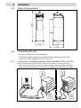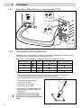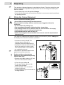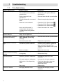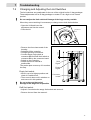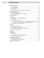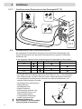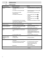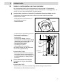
1
Operating Manual
Bedienungsanleitung
2 l Bag Reservoir
Reservoir für 2 l - Produktbeutel
97124
2
English .................................................................................................................... 5-17
Deutsch................................................................................................................... 19-31
3
Contents
1 Please observe the following ..............................................................................5
1.1
1.2
1.3
1.4
Emphasized Sections......................................................................................5
For Your Safety ...............................................................................................6
Items Supplied ................................................................................................5
Field of Application (Intended Usage) .............................................................6
2 Description ............................................................................................................6
2.1 Theory of Operation ........................................................................................6
2.2 Displays, Operating Elements and Connections.............................................7
3 Technical Data ......................................................................................................8
4 Installation.............................................................................................................8
4.1 Environmental and Operating Conditions .......................................................8
4.2 Space Requirements.......................................................................................9
4.3 Connecting the Unit.........................................................................................9
4.3.1 Connection of one Bag Reservoir to the Controller 97102 or 97103 ....9
4.3.2 Connection of Bag Reservoir to the Controller 97123.........................10
4.4 Changing the Piercing Element.....................................................................10
5 Dispensing ..........................................................................................................11
5.1
5.2
5.3
5.4
Filling the Product Reservoir .........................................................................11
Refilling the Product Reservoir......................................................................12
Shutdown for longer Periods.........................................................................12
Returning to Operation..................................................................................12
6 Cleaning...............................................................................................................13
7 Troubleshooting .................................................................................................14
7.1 Troubleshooting ............................................................................................14
7.2 Changing and Adjusting the Limit Switches ..................................................15
7.3 Replacing the Rupture Disk ..........................................................................16
8 Documentation....................................................................................................16
8.1 Accessories and Spare Parts........................................................................16
8.2 Pin Connection Reservoir .............................................................................17
9 Declaration of EC Confirmity.............................................................................17
4
1
1.1
Please observe the following
Emphasized Sections
Warning!
Refers to safety regulations and required safety measures that protect the
operator or other persons from injury or danger to life.
Caution!
Emphasizes what must be done or avoided so that the unit or other property is
not damaged.
Notice
Gives recommendations for better handling of the unit during operation or adjustment
as well as for service activities.
The numbers printed in bold in the text refer to the corresponding position numbers in
the illustration on page 7.
• The point emphasizes an instruction step.
1.2
For Your Safety
For safe and successful operation of the unit, read these instructions completely. The
manufacturer cannot be held responsible for damage or injury of any kind because of
misuse or improper application or because of failure to observe safety instructions or
warnings.
Be sure to retain this manual for future reference.
Refer to the technical data sheet of the assigned adhesive under the address
www.loctite.com or request the technical data sheet and the safety data sheet (acc. to
the EC Directive 91/155/EC) for the LOCTITE product used at
Henkel Loctite Deutschland GmbH
+49 89 92 68 11 67
for English version of data sheets;
089-92 68 11 22
for German version of data sheets.
Follow unconditionally the INSTRUCTIONS of these data sheets!
While under warranty, the unit may be repaired only by an authorized Loctite service
representative.
If chemical products are not properly handled, damage to health can result!
Observe general safety regulations for the handling of chemicals!
Observe manufacturer’s instructions!
Request a safety data sheet for the LOCTITE-product used!
When working with pressurized air, wear protective glasses!
Never fill the product directly into the
product reservoir!
The pneumatic safety devices would
become clogged and therefore
ineffective!
Insert only products packaged in closed
original LOCTITE containers!
Do not pierce the cap without having a
dispensing valve connected.
5
1
1.3
Please observe the following
Items Supplied
2 liter Bag Reservoir 97124
Tank Cord 97213
Product Fitting ¼”
Piercing Element 5 mm for high viscose products
Reservoir Tubing Set
0Operating manual
As a result of technical development, the illustrations and descriptions in this instruction
manual can deviate in detail from the actual unit delivered.
1.4
Field of Application (Intended Usage)
The Bag Reservoir 97124 is suitable for the application of LOCTITE-adhesives with a
dispensing valve at workstations such as in workshops, laboratories, and industrial
installations.
It can be used in conjunction with LOCTITE Controllers 97102, 97123, or 97103 for
supplying LOCTITE products to a dispensing valve.
LOCTITE-adhesives can be applied only from the original LOCTITE 2 l bag package.
No other size of products can be used.
2
2.1
Description
Theory of Operation
A 2 l bag package of Loctite product is loaded into the reservoir.
The Reservoir is then pressurized from a Loctite Controller using clean, filtered dry air.
The air pressure inside the vessel presses the product out of the bag package without
mechanical stress.
The dispensing pressure (regulated air from the controller) squeezes the bag and
transport the product through the piercing element, the product fitting and the feedline to
the dispensing valve. An integrated pneumatic cylinder presses a pusher plate against
the bag in a controlled way. This action avoids twisting and closing of the bag.
The amount of product dispensed is controlled by three main factors:
– Amount of pressure pushing on the bag package.
– Length of time the dispensing valve remains open.
– Dispensing Needle size.
When the hand lever valve is in position On and the reservoir is connected to Controller
97102 or 97123, it is pressurized automatically when the controller is switched on and
depressurized automatically when the controller is switched off.
When the package is empty the indication “empty” appears as blinking text on the digital
display of the controller and on the panel of the bag reservoir as a shining red LED. In
addition, a beeping tone will be heard from the controller. With the error message
“empty”, the controller 97123 automatically depressurizes the reservoir. The return
travel of the piston is performed manually on the hand lever valve.
6
2
2.2
Description
Displays, Operating Elements and Connections
1
2 3
4,5
6
7
1
Reservoir Knobs
2
Reservoir Lid
3
Product Fitting ¼” for product feedline
4
Screw Collar
5
Piercing Element
6
Spout Holders
7
LED´s
Power
Lights when the unit is being
supplied
(green) with electrical power.
8
Refill
Lights when the bag is nearly empty(yellow) the next bag package should be
prepared for use.
Empty
(red)
8
13
If this LED lights, the reservoir is
depressurized automatically by the
controller 97123. The return travel
of the piston is performed manually
on the hand lever valve (see
Section 5.2).
Hand Lever Valve
Position Action
9
On
Cylinder (piston) up.
Off
Cylinder depressurized
(pressure-free).
Change
Cylinder (piston) down for replacing the
bag package.
Socket XS2/OUT
The controller 97102, 97123, 97103 or a PLC
is connected here.
10
With the connection of two bag reservoirs on a
Controller 97103, the reservoir B is connected
here.
9
10
;6RXW
3LQ
EDU
11
;6LQ
2
,
12
12
Equipment Connector XS2/IN
11
Pneumatic Connection
Hose O
(outlet)
Supplies the controller with
pressurized air for regulator input.
Hose I
(inlet)
Supplies the product reservoir with
regulated pressurized air from the
controller’s regulator output.
Pneumatic Connection (P in)
Connection for the external pneumatic
supply 4-8 bar (58 - 115 psi).
13
Wall Mounting bracket
Accessory, Order code no. 97277.
7
3
4
4.1
Technical Data
Pneumatic supply
Min. 4 bar (58 psi), max. 8 bar (115 psi)
Quality
If the required quality is not
achieved, install a LOCTITE
filter regulator.
Filtered 10 µm, oil-free, non-condensing
Over-pressure safety
(rupture disc)
min. 9 bar (130.5 psi); max. 12.5 bar (174 psi)
Tightening torque of the rupture disc max. 20 Nm
Dimensions without wall
bracket
W x H x D: 187 x 690 x 238 mm (7.37 x 27.2 x 9.37
inch)
Dimensions with wall bracket
W x H x D: 187 x 690 x 308 mm (7.37 x 27.2 x 12.2
inch)
Pneumatic hose size
pneum. Connect.
Internal dia. 4 mm; external dia. 6 mm +0.05, -0.10
External dia. ¼ in. is not suitable!
Operating temperature
+10° C to +40° C (+50° F to +104° F)
Storage temperature
–10° C to +60° C (+14° F to +140° F)
Protection grade
IP 23 acc. to VDE 0470, Part 1/EN 60529-1991
Weight
13 kg
Accessory Order No. 97120
Installation
Environmental and Operating Conditions
– Keep product feed lines as short as possible. The shorter the feedline the smaller the
specific resistance and the lower the dispensing pressure can be. Avoid kinking.
– In any cases, the pressure hose and product feedline should not be longer than 2 m.
– Do not use inflexible hoses and feed lines, to avoid unnecessary loads on the fittings.
– Keep all fittings tight.
– No direct sunlight; no UV light.
– No condensing humidity.
– Avoid water splashes.
8
4
Space Requirements
690 mm
27.2 inch
4.2
Installation
238 mm
9.4 inch
308 mm
12.1 inch
187 mm
7.4 inch
4.3
Connecting the Unit
• Use only the cable and hose sets supplied.
• Connect air pressure supply to pneumatic connection 12 with pneumatic hose
internal dia. 4 mm, external dia. 6 mm +0.05, -0.10.
Connection of one Bag Reservoir to the Controller 97102 or 97103
When Semiautomatic Controller 97102 is used, connect reservoir with tubing set 97267:
• Connect the coax tube to the Y splitter, the calibrated tube to the outlet I and the pneumatic
supply to the inlet 0 of the splitter, see Pneumatic Schematic Coaxial Connection (Y-splitter).
97103
XS1:
XS2: Start
XS3: Reservoi
r
XS4: Turntable
XS5: DC Motor
XS6: Monitor
A
XS7: Monitor
B
XS8: RS232
Ma
XS9: RS232 ster
Sla
XS10:PLC Inte ve
rfac
e
XS11: I/O por
t
XS12: Servo
ChannA/B
el A/B
XS3
XS
1:
XS Start
2: Re
servo
XS 2 in
ir
XS2
I
Locti
te (Ir
Mad
90–
260
XS1
O
XS2
XS 2 out
P in
6-8 bar
e in
cat
Ger
y
.97
C/4
7–6
2 AM
3 Hz
Loctit
ela
man
.no
VA
102
nd)
XS12
XS4
XS11
XS5
XS10
XS6
XS9
XS7
XS8
97102
XS1
4.3.1
Mad
85–
Ltd
264
.
e in
VAC
/50–
440
2 AM
cat.
e (Ire
Germ
any
no.9
710
3
Hz
land)
Ltd.
A
B
0
0
I
I
9
4
4.3.2
Installation
Connection of Bag Reservoir to the Controller 97123
0
1
P in
6-8
bar
B
A
XS 2 out
P in
6-8 bar
0
XS 2 in
O
I
1
0
XS6
XS7
XS8
1
XS3
Flow
Mon
itor
XS2
Res
ervo
ir
XS1
XS4
RS23
2
Sta
rt
XS5
90-2
PLC
47-660 VA
Inte
rface
Phas3 Hz C
e=
1
2 AM
cat.
no.
Mad
e in
Loc
ti
971
23
Ge
rman
y
Tal te
(I
la
Whi ght B rela
n
us
te
Tal stow iness d) L
lagh n
Par td.
t, D
k
ublin
24,
Irel
and
Powe
r
cons
um
ption
max
. 60
W
XS 2
4.4
Changing the Piercing Element
The built-in piercing element 5 is suitable for most of the applications. However, some
applications may need the large bore-piercing element.
Below there is a table where you find the usage of the piercing element 5.
Piercing element
Drops
Beads
Low viscose product
High viscose product
1 mm
5 mm
1 mm
5 mm
Explanations:
- Drops mean an amount of product, which becomes a size up to approximately
∅ 5 mm. All the other which are bigger than drops are beads.
- Low viscose means product up to 1,000 mPas, all others are high viscose.
•
•
•
•
•
Disassemble product fitting 3.
Unscrew the collar 4.
Unscrew the grub screws.
Remove the screw collar.
Remove the circlip and the piercing
element 5 will be released from the
screw collar.
• Reassemble in the reverse order.
Product residue on the piercing
element! Do not contaminate it with
dust!
10
3
4
5
5
Dispensing
The operation of the bag dispenser is described as follows. Follow the instructions step
by step. Otherwise it is possible that product will run out of the bag and rendering the
reservoir useless.
• Set the hand lever valve 8 to position Change.
• Check that the dispensing valve and the controller is correctly connected according to
its operating manual.
5.1
Filling the Product Reservoir
Please consider the following points:
• Never fill the product directly into the reservoir!
The pneumatic and safety devices would become clogged and therefore
ineffective!
• Do not remove the package cap.
• The unregulated pneumatic supply should be at least 4 bar.
• The package should not be removed from the reservoir before it is empty.
• Pressurize the reservoir before piercing the cap.
• Only load the reservoir with full bag (2 l).
• Before loosening the reservoir knobs 1, the reservoir must be depressurized
(pressure-free)!
The reservoir is depressurized when the hand lever valve 8 is in position Change and
the display at the controller indicates no pressure.
• Unscrew the screw collar 4. The
piercing element 5 should be
completely retracted inside the lid 2.
• Unscrew the reservoir knobs 1 until the
lid 2 of the reservoir is free to rotate.
The reservoir knobs 1 do not have to
be completely removed.
The lid can be placed as shown in the
graphic to have the hands free.
Product residue on the piercing
element! Do not contaminate piercing
element with dust!
• Remove the lid 2 by rotating it 45° and
lift it free of the reservoir knobs 1.
• Lift out the spout holders 6.
• Fit the spout holders 6 around the
nozzle of the package.
• Check that there is no condensed
moisture at the bag.
• Lift the package by spout holders 6 into
the bag reservoir.
11
5
Dispensing
A ledge near the top of the reservoir supports the spout holders 6. Make sure the bag is
not trapped between this ledge and the spout holders 6.
Make sure screw collar 4 is completely unscrewed. The piercing element 5 should be
completely retracted inside the lid 2.
Do not remove the package cap.
• Fit the lid 2 onto the dispenser.
• Tighten all four reservoir knobs 1.
Make sure that they are seated inside their recesses on lid 2.
• Set the hand lever valve 8 to position On.
• On the 97102 Controller, switch the reservoir on with button
On the 97123 Controller, switch the reservoir on with button
On the 97103 Controller, switch the reservoir on with button
5.2
.
.
.
Refilling the Product Reservoir
• Set the hand lever valve 8 to Change.
• Lift the piercing element 5 by unscrewing the screw collar 4.
• Unscrew the reservoir knobs 2 until the lid 1 is free to rotate. The reservoir knobs 2 do
not have to be completely removed.
Product residue on the piercing element! Do not contaminate the piercing
element with dust!
• Remove the lid 2 by rotating it 45° and lift it free of the reservoir knobs 1.
• Lift out the spout holders 6. The empty bag package will come away with the spout
holders.
• Remove the spout holders 6 of the empty bag package.
• Insert a new bag package according to Section 5.1.
Never insert a used or semi full bag. Do not refill an empty bag. This causes
trouble during dispensing as air can be entrapped.
• Screw down the screw collar 4.
• Set the hand lever valve 8 to position On.
5.3
Shutdown for longer Periods
• Move hand lever valve 8 into the Off position.
• Disconnect the pneumatic supply from the controller.
5.4
Returning to Operation
• Reconnect the pneumatic supply to the controller.
• Check the installation according to Chapter 4.
• Return to operation according to Section 5.1.
12
6
Cleaning
The unit requires no special care and maintenance.
• Clean or renew piercing element 5.
• Clean contaminated wall in the vessel.
Do not use metal tools for cleaning the piercing element. Anaerobic products can cure
on contact with metal. Remove product residue as required.
When changing the type of product, renew the product hose and dispensing valve (see
operating instructions of the dispensing valve).
• Add silicone grease to the O-ring and the screw of the piercing element for protection
and lubrication.
• Check both the reservoir knobs 1 and the product feedline on a regular basis. If there
is any sign of cracks, replace them!
13
7
7.1
Troubleshooting
Troubleshooting
Type of Malfunction
Possible Causes
Corrections
No adhesive is dispensed.
– Product reservoir is empty.
The red LED on the automatic
reservoir is lit.
• Refill the product reservoir
(Section 5.2) The yellow LED was
previously lit.
– Product reservoir is not
switched on.
• Set hand lever valve 8 to position On.
– Piercing element 5 not screwed
down.
• Screw down piercing element 5.
– Reservoir is not activated.
• Controller 97102: Press button
.
• Controller 97103: Press button
.
• Controller 97123: Press button
.
– Inner wall of the vessel is
contaminated with product.
Cylinder cannot bring pusher
plate up.
• Clean inner wall of the vessel.
Product emerges at the
product fitting 3.
– Union nut on the product
fitting 3 is not tightened.
• Carefully tighten union nut.
Pressurized air escapes in
the reservoir housing.
– Hand lever valve 8 in position
Off or Change (replace bag
package).
• Set hand lever valve 8 to position On.
– Punctured rupture disc.
• Replace the rupture disc.
– Lose plug or socket of the tank
cord on the product reservoir.
• Switch the power switch (controller)
to the O (OFF) position. Tighten the
plug or socket of the tank cord.
Switch the power switch to the I (ON)
position.
– Tank cord defect.
• Replace the tank cord.
Pressurized air escapes
between reservoir housing
and lid.
– Reservoir knobs not tightened.
• Tighten the reservoir knobs.
– O-ring leaky.
• Grease the O-ring.
Too little product.
– Reservoir pressure inadequate.
• Increase the pressure on the
controller.
– Air supply pressure inadequate.
• Increase the air supply pressure.
– Malfunction of the dispensing
valve.
• Check the dispensing valve (see
operating instructions of the
dispensing valve).
– Bag empty.
• Replace bag.
– Air supply less than 4 bar.
• Increase the air supply to 4 bar
minimum.
LED indicator 7 does not
light.
Too much residue.
14
7.2
Troubleshooting
Changing and Adjusting the Limit Switches
The limit switches are preadjusted for the use of the original Loctite 2 l bag packages.
These adjustments are for all bag packages no matter if it is a high or low viscose
product.
Do not readjust the limit switches! Damage of the bags can be possible.
When they are not working it is necessary to change one or both limit switches.
• Open the lid 2 and insert the
adjustment tool into the vessel.
• Close the lid.
Adjustment
Tool
PP
• Remove the front sheet metal of the
housing.
• Switched off the controller.
• Change the faulty limit switch.
• Connect Empty limit switch at
connector P2 and Refill limit switch at
connector P3 on the connector board.
• Switch on the Controller.
• Switch hand lever valve 8 in
position On.
The pusher plate moves up till it reaches
the stop.
5 mm
0.19 inch
7
Refill
Signal
Empty
Signal
Empty limit switch:
• Move it up to its highest position and
check it is switched off.
• Then move it down until it switches on
and secure it in this position.
Connector
board
Do not go beyond that point!
Damage of the bags can be possible.
Refill limit switch:
• Adjust it 5 mm below the empty limit switch and secure it.
• Remove the tool from the reservoir.
15
7
7.3
Troubleshooting
Replacing the Rupture Disk
When the maximum allowable air supply pressure is exceeded, the bursting of the
rupture disc depressurizes the reservoir. The punctured rupture disc must be replaced.
• Remove the front sheet metal of the
housing.
• Remove the rupture disc screw.
• Replace the punctured rupture disc
with a new one.
• Replace and tighten the rupture disc
screw.
Tightening torque: maximum 20 Nm.
Affix the supplied type plate.
20 Nm
• Close the housing. Insert and tighten the screws.
8
8.1
Documentation
Accessories and Spare Parts
Also see the illustration on page 7.
Pos.
No.
16
Description
Loctite Order
No.
5
Piercing Element Ø 1 mm
97278
–
Piercing Element Ø 5 mm
97279
6
Spout holders
97209
8
Hand Lever Valve,
Order code no. 34 539-HSO-4/3-M5, Festo
–
O Ring (Lid),
Dimensions: 129.77*3.53 mm, Material: EPDM
–
Filter Regulator
97120
–
Tank Cord
97213
–
Limit switch (incl. tool for adjustment)
97814
–
Pressure Regulator 0-9 bar, QS Connections
8960749
8
8.2
Documentation
Pin Connection Reservoir
Never connect external voltage on pin 1 or pin 9!
Controller XS2
1
2
Bag Reservoir
Tank REFILL
Tank EMPTY
Signal
1
1
2
2
1
2
1
Tank REFILL
3
3
4
4
5
5
1
Tank EMPTY
6
7
7
8
9
9
0 VDC
6
Identification
Signal
8
+ 24 VDC
9
0
0
GND
Declaration of EC Conformity
Declaration of Conformity
The Manufacturer
according to the EC regulations
Henkel Loctite Deutschland GmbH
Arabellastraße 17
D-81925 München
declares that the unit designated in the following is, as a result of its design and construction, in accordance
with the European regulations, harmonized standards and national standards listed below.
Designation of the unit
2 l Bag Reservoir
Unit number
97124
Applicable EC Regulations
EC Directive of Machinery 98/37/EEC including change
98/79/EC
Applicable harmonized standards
DIN EN ISO 12100-1:2004-04 (former DIN 292-1), DIN EN
ISO 12100-2:2004-04 (former DIN 292-2)
Date/Manufacturer’s signature
09/09/2004
(A. Gschiel)
This declaration is not valid if there are any changes not approved by Henkel Loctite.
17
Inhaltsverzeichnis
1 Bitte beachten Sie...............................................................................................19
1.1
1.2
1.3
1.4
Hervorhebungen ...........................................................................................19
Zu Ihrer Sicherheit.........................................................................................20
Lieferumfang .................................................................................................19
Einsatzbereich (Bestimmungsgemäße Verwendung) ...................................20
2 Gerätebeschreibung...........................................................................................20
2.1 Funktionsbeschreibung .................................................................................20
2.2 Anzeigen, Bedienelemente und Anschlüsse.................................................21
3 Technische Daten ...............................................................................................22
4 Installieren...........................................................................................................22
4.1 Umgebungs- und Betriebsbedingungen........................................................22
4.2 Platzbedarf ....................................................................................................23
4.3 Anschließen des Gerätes..............................................................................23
4.3.1 Anschluß eines Reservoirs an das Steuergerät 97102 oder 97103....23
4.3.2 Anschluß eines Reservoirs an das Steuergerät 97123.......................24
4.4 Austauschen des Durchstechdorns ..............................................................24
5 Dosieren ..............................................................................................................25
5.1
5.2
5.3
5.4
Füllen des Produkttanks................................................................................25
Nachfüllen des Produkttanks ........................................................................26
Außerbetriebnahme für längere Stillstandszeiten .........................................26
Erneute Inbetriebnahme................................................................................26
6 Reinigung ............................................................................................................27
7 Fehlersuche.........................................................................................................28
7.1 Fehlersuche ..................................................................................................28
7.2 Ändern und Einstellen der Grenzschalter .....................................................29
7.3 Austauschen der Berstscheibe .....................................................................30
8 Technische Unterlagen ......................................................................................30
8.1 Zubehör und Ersatzteile ................................................................................30
8.2 Steckerbelegung am Produkttank .................................................................31
9 EG-Konformitätserklärung.................................................................................31
18
1
1.1
Bitte beachten Sie
Hervorhebungen
Gefahr!
Verweist auf Sicherheitsregeln und fordert Vorsichtsmaßnahmen, die den
Betreiber des Gerätes oder andere Personen vor Verletzungen oder Lebensgefahr
schützen.
Achtung!
Hebt hervor, was getan oder unterlassen werden muss, um das Gerät oder
andere Sachwerte nicht zu beschädigen.
Hinweis
Gibt Empfehlungen zum besseren Handhaben des Gerätes bei Bedien- und
Einstellvorgängen sowie Pflegearbeiten.
Die fett gedruckten Zahlen im Text beziehen sich auf die entsprechende
Positionsnummer
in der Abbildung auf Seite 21.
• Der Punkt hebt einen Handlungsschritt hervor.
1.2
Zu Ihrer Sicherheit
Für den gefahrlosen und erfolgreichen Einsatz des Gerätes diese Anleitung vollständig
lesen. Der Hersteller kann nicht für Schäden verantwortlich gemacht werden, die infolge
der Nutzung abweichend vom bestimmungsgemäßen Gebrauch oder der
Nichtbeachtung von Sicherheitshinweisen oder Warnungen verursacht werden.
Bewahren Sie diese Anleitung nach Durchsicht griffbereit auf.
Beziehen sie sich auf das technische Datenblatt des eingesetzten Klebstoffes unter der
Adresse www.loctite.com oder fordern Sie das technische Datenblatt und das
Sicherheitsdatenblatt (nach EU-Richtlinie 91/155/EC) an bei
Henkel Loctite Deutschland GmbH
+49 89 92 68 11 67
für die englische Version des Datenblattes;
089-92 68 11 22
für die deutsche Version des Datenblattes.
Befolgen Sie unbedingt den Anweisungen dieser Datenblätter!
Bei unsachgemäßem Umgang mit chemischen Produkten können
Gesundheitsschäden auftreten!
Allgemeine Sicherheitsvorschriften für den Umgang mit Chemikalien beachten!
Herstellerhinweise beachten! Sicherheitsdatenblatt des eingesetzten LOCTITEProdukts anfordern!
Beim Arbeiten mit Druckluft Schutzbrille tragen!
Niemals das Produkt direkt in den
Produkttank füllen!
Die pneumatischen SicherheitsEinrichtungen werden verklebt und
dadurch unwirksam!
Das Produkt nur im geschlossenen
LOCTITE-Originalgebinde einsetzen!
Den Verschluss niemals ohne
angeschlossenes Dosierventil öffnen.
19
1
1.3
Bitte beachten Sie
Lieferumfang
Reservoir für 2-l-Produktbeutel 97124 Durchstechdorn 5 mm für hochviskose Produkte
Anschlusskabel 97213
Schlauchset für Produkttank
¼"-Produktanschluss
Bedienungsanleitung
Bedingt durch die technische Entwicklung können Abbildungen und Beschreibungen in
dieser Bedienungsanleitung vom tatsächlich ausgelieferten Gerät in Details abweichen.
1.4
Einsatzbereich (Bestimmungsgemäße Verwendung)
Das Reservoir für Produktbeutel 97124 eignet sich zum Auftragen von LOCTITEKlebstoffen mit einem Dosierventil an Arbeitsplätzen wie Werkstätten, Labors und
industriellen Einrichtungen.
Es wird in Verbindung mit den LOCTITE-Steuergeräten 97102, 97123 und 97103 zum
Versorgen eines Dosierventils mit LOCTITE-Produkten eingesetzt.
LOCTITE-Klebstoffe können nur aus dem Original-LOCTITE-2-l-Produktbeutel
aufgetragen werden. Die Verwendung anderer Produktgrößen ist nicht möglich.
2
2.1
Gerätebeschreibung
Funktionsbeschreibung
Ein 2-l-Beutel des Loctite-Produkts wird in den Produkttank eingesetzt.
Der Produkttank wird anschließend vom LOCTITE-Steuergerät mit sauberer, gefilterter
trockener Luft belüftet. Durch den Druck im Behälter wird das Produkt ohne
mechanische Beanspruchung aus dem Beutel gepresst.
Durch den Dosierdruck (geregelte Luft vom Steuergerät) wird der Beutel
zusammengedrückt und das Produkt durch das Durchstechdorn, den Produktanschluss
und den Produktschlauch zum Dosierventil transportiert. Ein integrierter
Pneumatikzylinder drückt auf geregelte Weise ein Kolben gegen den Beutel. Dadurch
wird ein Abdrehen des Beutels verhindert.
Die Dosiermenge wird durch die folgenden drei Hauptfaktoren bestimmt:
– Auf den Beutel ausgeübter Druck.
– Öffnungszeit des Dosierventils.
– Größe der Dosiernadel.
Wenn sich das Handhebelventil in Position 'Ein' (On) befindet und der Produkttank an
das Steuergerät 97102 oder 97123 angeschlossen ist, wird dieser beim Einschalten des
Steuergeräts automatisch belüftet und beim Ausschalten des Steuergeräts automatisch
entlüftet.
Ist der Beutel leer, wird in der Digitalanzeige am Steuergerät die Meldung Leer (Empty)
und am Reservoir für Produktbeutel eine rote LED angezeigt. Sie wird zusätzlich vom
Steuergerät durch einen Piepton signalisiert. Bei der Fehlermeldung Leer (Empty) wird
der Produkttank sofort automatisch vom Steuergerät 97123 entlüftet. Die Rückführung
des Kolbens erfolgt manuell mit dem Handhebelventil.
20
2
2.2
Gerätebeschreibung
Anzeigen, Bedienelemente und Anschlüsse
1
2 3
4,5
6
7
1
Deckelverschraubung
2
Deckel
3
Produktanschluss für ¼"-Produktschlauch
4
Drehgriff für Durchstechdorn
5
Durchstechdorn
6
Beutelhalterungen
7
LEDs
Netz (Power) = Leuchtet, wenn das Gerät
(grün)
mit Strom versorgt ist.
Nachfüllen = Leuchtet, wenn der Beutel
(Refill) (gelb) fast leer ist. Der nächste
Produktbeutel muss für die
Verwendung vorbereitet
werden.
8
Leer (Empty) = Leuchtet diese LED, wird der
(rot)
Tank automatisch durch das
Steuergerät 97123 entlüftet.
Die Rückführung des Kolbens erfolgt manuell
mit dem Handhebelventil (siehe Abschnitt 5.2).
8
13
Handhebelventil
Position
Aktion
Ein (On)
Zylinder (Kolben) oben.
Aus (Off)
Zylinder entlüftet (drucklos).
Auswechseln Zylinder (Kolben) unten
(Change)
(Produktbeutelwechsel).
9
Buchse XS2/OUT
Anschluss für Steuergeräte 97102, 97123,
97103 oder SPS.
10
9
10
;6RXW
3LQ
EDU
Bei Anschluss von zwei Reservoirs an das
Steuergerät 97103 wird Reservoir B hier
angeschlossen.
11
Druckluftanschluss
Schlauch O – Versorgt das Steuergerät mit
(Ausgang)
Druckluft für Reglereingang.
;6LQ
2
Geräteanschluss XS2/IN
,
Schlauch I
(Eingang)
12
11
12
– Versorgt den Produkttank mit
geregelter Druckluft vom
Reglerausgang des
Steuergeräts.
Druckluftanschluss (P in)
Anschluss für externe Druckluftversorgung
4 - 8 bar (58 - 115 psi)
13
Halterung für Wandbefestigung
Zubehör-Bestellnr. 97277.
21
3
4
4.1
Technische Daten
Druckluftversorgung
min. 4 bar (58 psi), max. 8 Bar (115 psi)
Qualität
Wird die erforderliche
Qualität nicht erreicht, ist
ein LOCTITE-Filterregler
zu installieren.
Gefiltert 10 µm, ölfrei, nicht kondensierend
Überdrucksicherheit
(Berstscheibe)
min. 9 bar (130 psi); max. 12,5 bar (174 psi)
Anzugsmoment der Berstscheibe max. 20 Nm
Abmessungen ohne
Wandhalterung
B x H x T: 187 x 690 x 238 mm
Abmessungen mit
Wandhalterung
B x H x T: 187 x 690 x 308 mm
Größe Pneumatikschlauch
pneum. Anschluss
Innendurchm. 4 mm; Außendurchm. 6 mm +0,05, -0,10
Außendurchm. ¼ Zoll ist nicht geeignet!
Betriebstemperatur
+10 °C bis +40 °C
Lagertemperatur
–10 °C bis +60 °C
Schutzgrad
IP 23 nach VDE 0470, Teil 1/EN 60529-1991
Gewicht
13 kg
Zubehör-Bestellnr. 97120
Installieren
Umgebungs- und Betriebsbedingungen
– Produktschläuche so kurz wie möglich halten. Je kürzer der Schlauch, desto geringer
der spezifische Widerstand und somit der Dosierdruck. Knicken des Schlauchs
vermeiden.
– Produktschlauch und Druckschlauch sollten auf keinen Fall länger sein als 2 m.
– Keine starren Druck- und Produktschläuche verwenden, um unnötige Belastungen der
Anschlüsse zu vermeiden.
– Alle Anschlüsse müssen dicht sein.
– Direkte Sonneneinstrahlung und UV-Licht vermeiden!
– Keine kondensierende Feuchtigkeit.
– Kein Spritzwasser.
22
Installieren
4.2
Platzbedarf
690 mm
27.2 inch
4
238 mm
9.4 inch
308 mm
12.1 inch
187 mm
7.4 inch
4.3
Anschließen des Gerätes
• Nur die mitgelieferten Kabel und Schlauchsets verwenden.
• Druckluftversorgung an Druckluftanschluss 12 mit Druckschlauch
anschließen (Innendurchmesser 4 mm, Außendurchmesser 6 mm +0,05, -0,10).
Anschluss eines Reservoirs an das Steuergerät 97102 oder 97103
Bei Verwendung des halbautomatischen Steuergeräts 97102 muss der Produkttank mit
dem Schlauchset 97267 angeschlossen werden:
• Den koaxialen Schlauch an den Y-Splitter, den kalibrierten Schlauch an den
Ausgang I und die Druckluftversorgung an den Eingang 0 des Splitters anschließen.
97103
XS1:
XS2: Start
XS3: Reserv
oir
XS4: Turntable
XS5: DC Motor
XS6: Monitor
A
XS7: Monitor
B
XS8: RS232
Ma
XS9: RS232 ster
Sla
XS10:PLC Inte ve
rfac
e
XS11: I/O por
t
XS12: Servo
Cha A/B
nne
l A/B
XS3
XS
1:
XS Start
2: Re
servo
XS 2 in
ir
XS2
I
Locti
te (Ir
Mad
90–
260
XS1
O
XS2
XS 2 out
P in
6-8 bar
e in
cat
VAC
/47–
2 AM 63 Hz
Ger
y
.97
Loctit
ela
man
.no
102
nd)
XS12
XS4
XS11
XS5
XS10
XS6
XS9
XS7
XS8
97102
XS1
4.3.1
Made
85–
Ltd
264
.
VAC
/50–
440
2 AM
cat.
e (Ire
in Germ
any
no.9
710
3
Hz
land)
Ltd.
A
B
0
0
I
I
23
4
4.3.2
Installieren
Anschluss eines Reservoirs an das Steuergerät 97123
0
1
P in
6-8
bar
B
A
XS 2 out
P in
6-8 bar
0
XS 2 in
O
I
1
0
XS6
XS7
XS8
1
XS3
Flow
Mon
itor
XS2
Res
ervo
ir
XS1
XS4
RS23
2
Sta
rt
X
S5
90-2
PLC
47-660 VA
Inte
rface
Phas3 Hz C
e=
1
2 AM
cat.
no.
Mad
e in
Loc
971
23
Ge
any
Tal tite
(I
la
Whi ght B rela
n
us
te
Tal stow iness d) L
lagh n
Par td.
t, D
k
ublin
24,
Irel
and
Powe
r
rm
cons
um
ption
max
. 60
W
XS 2
4.4
Austauschen des Durchstechdorns
Der eingebaute Durchstechdorn 5 eignet sich für die meisten Anwendungen. Bei
einigen Anwendungen kann jedoch der Durchstechdorn mit großem Durchmesser
erforderlich sein.
In der folgenden Tabelle wird die Verwendung des Durchstechdorns 5 beschrieben.
Durchstechdorn-Ø
Tropfen
Raupen
Niedrigviskose Produkte
Hochviskose Produkte
1 mm
5 mm
1 mm
5 mm
Erläuterungen:
– Als Tropfen wird die Produktmenge bis zu einer Größe von ca. ∅ 5 mm bezeichnet.
Alle Produktmengen, die größer sind als Tropfen, werden als Raupen bezeichnet.
– Als niedrigviskose Produkte werden Produkte mit 1.000 mPas bezeichnet, alle
anderen sind hochviskose Produkte.
•
•
•
•
•
Produktanschluss 3 demontieren.
Drehgriff 4 lösen.
Gewindestifte lösen.
Drehgriff entfernen.
Sicherungsring entfernen. Der
Durchstechdorn 5 kann vom
Drehgriff gelöst werden.
• In umgekehrter Reihenfolge
wieder zusammensetzen.
Produktrückstände auf
Durchstechdorn! Durchstechdorn
nicht mit Staub verschmutzen!
24
3
4
5
5
Dosieren
Die Funktionsweise des Beutelreservoirs wird im folgenden beschrieben. Anweisungen
Schritt für Schritt durchführen. Anderenfalls könnte Produkt aus dem Beutel austreten
und den Produkttank unbrauchbar machen.
• Handhebelventil 8 auf Stellung Auswechseln (Change) umschalten.
• Prüfen, dass Dosierventil und Steuergerät gemäß der entsprechenden
Bedienungsanleitungen korrekt angeschlossen sind.
5.1
Füllen des Produkttanks
Folgende Punkte sind zu beachten:
• Niemals das Produkt direkt in den Tank füllen!
Die Pneumatik und die Sicherheitseinrichtungen werden verstopft und somit
unbrauchbar!
• Beutelverschluss nicht entfernen.
• Ungeregelte Druckluftversorgung sollte mindestens 4 bar betragen.
• Beutel erst nach vollständiger Entleerung aus Produkttank entfernen.
• Produkttank nur mit vollem Beutel (2 l) bestücken.
• Produkttank vor Durchstechen des Verschlusses belüften.
• Vor dem Lösen der Deckelverschraubung 1 muss der Produkttank entlüftet
(drucklos) sein!
Entlüftung des Produkttanks erfolgt, wenn das Handhebelventil 8 auf Stellung
Auswechseln (Change) umgeschaltet ist und die Anzeige am Steuergerät anzeigt,
dass der Behälter drucklos ist.
• Drehgriff 4 lösen. Der Durchstechdorn
5 muss sich vollständig im Deckel 2
befinden.
• Deckelverschraubung 1 lösen, bis sich
der Deckel 2 des Produkttanks drehen
lässt. Die Deckelverschraubung 1
muss nicht vollständig gelöst werden.
Um die Hände frei zu haben, den Deckel
wie in der Grafik gezeigt einhängen
Produktrückstände auf
Durchstechdorn! Durchstechdorn
nicht mit Staub verschmutzen!
• Deckel 2 durch Drehung um 45°
• Beutelhalterungen 6 herausheben.
• Beutelhalterungen 6 auf die Nadel des
Beutels aufsetzen.
• Prüfen, dass sich keine
Kondensflüssigkeit auf dem Beutel
befindet.
• Beutel an den Beutelhalterungen 6
anheben und in den Produkttank
einsetzen.
25
5
Dosieren
Die Beutelhalterungen 6 liegen auf einer Leiste oben am Produkttank auf. Prüfen, dass
der Beutel nicht zwischen Leiste und Beutelhalterungen 6 eingeklemmt ist.
Prüfen, dass Drehgriff 4 vollständig gelöst ist. Der Durchstechdorn 5 muss sich
vollständig im Deckel 2 befinden.
Beutelverschluss nicht entfernen.
• Drehgriff 4 wieder festschrauben.
• Deckel 2 auf das Dosiergerät aufsetzen.
• Die vier Deckelverschraubungen 1 wieder festziehen.
Prüfen, dass die Verschraubungen in den entsprechenden Aussparungen im Deckel 2
sitzen.
• Handhebelventil 8 auf Stellung Ein (On) umschalten.
• Den Produkttank am Steuergerät 97102 mit der Taste
Den Produkttank am Steuergerät 97123 mit der Taste
Den Produkttank am Steuergerät 97103 mit der Taste
5.2
einschalten.
einschalten.
einschalten.
Nachfüllen des Produkttanks
• Handhebelventil 8 auf Auswechseln (Change) umschalten.
• Durchstechdorn 5 durch Lösen des Drehgriffes 4 anheben.
• Deckelverschraubung 1 lösen, bis sich der Deckel 2 des Produkttanks drehen lässt.
Die Deckelverschraubung 1 muss nicht vollständig gelöst werden.
Produktrückstände auf Durchstechdorn! Durchstechdorn nicht mit Staub
verschmutzen!
• Deckel 2 durch Drehung um 45° entfernen und von Deckelverschraubung 1 lösen.
• Beutelhalterungen 6 herausheben. Der leere Produktbeutel wird mit den
Beutelhalterungen herausgenommen.
• Beutelhalterungen 6 des leeren Produktbeutels abnehmen.
• Neuen Produktbeutel gemäß der Anweisungen in Abschnitt 5.1 einsetzen.
Niemals gebrauchten oder halbvollen Beutel einsetzen. Leeren Beutel nicht
auffüllen. Dadurch kann es zu Lufteinschlüssen kommen, die beim Dosieren
Probleme verursachen können.
• Drehgriff 4 wieder festschrauben.
• Handhebelventil 8 auf Stellung Ein (On) umschalten.
5.3
Außerbetriebnahme für längere Stillstandszeiten
• Handhebelventil 8 auf Stellung Aus (Off) umschalten.
• Die Druckluftversorgung des Steuergerätes unterbrechen.
5.4
Erneute Inbetriebnahme
• Druckluftversorgung des Steuergerätes wiederherstellen.
• Installation gemäß Kapitel 4 überprüfen.
• Inbetriebnahme gemäß Abschnitt 5.1.
26
6
Reinigung
Das Gerät bedarf keiner besonderen Pflege und Wartung.
• Durchstechdorn 5 regelmäßig reinigen und gegebenenfalls auswechseln.
• Verschmutzte Behälterwände reinigen.
Bei der Reinigung des Durchstechdorns keine Metallwerkzeuge verwenden. Anaerobe
Produkte härten bei Metallkontakt aus. Gegebenenfalls Produktrückstände entfernen.
Bei Produktwechsel Produktschlauch und Dosierventil erneuern (siehe Anweisungen im
Handbuch des Dosierventils).
• Zwecks Schutz und Schmierung Silikonfett auf O-Ringe und Gewinde des
Durchstechdorns auftragen.
• Deckelverschraubung 1 und Produktschlauch in regelmäßigen Abständen überprüfen.
Auswechseln, sobald undichte Stellen oder Rissbildung erkennbar sind!
27
7
7.1
Fehlersuche
Fehlersuche
Art der Störung
Mögliche Ursachen
Abhilfe
Es wird kein Klebstoff
dosiert.
– Produkttank leer.
Am Automatikbehälter leuchtet
rote LED.
• Produkttank auffüllen (Abschnitt 5.2)
Die gelbe LED hat zuvor geleuchtet.
– Produkttank nicht eingeschaltet.
• Handhebelventil 8 auf Stellung Ein
(On) umschalten.
– Durchstechdorn 5 nicht
festgeschraubt.
• Durchstechdorn 5 festschrauben.
– Produkttank nicht aktiviert.
• Steuergerät 97102: Taste
drücken.
• Steuergerät 97103: Taste
drücken.
• Steuergerät 97123: Taste
drücken.
– Produktrückstände auf Innenwand
des Behälters. Zylinder kann Kolben
nicht nach oben bewegen.
• Innenwand des Behälters reinigen.
Produkt tritt an Produktanschluss 3 aus.
– Überwurfmutter an ProduktAnschluss 3 nicht festgezogen.
• Überwurfmutter vorsichtig
nachziehen.
Druckluft entweicht im
Produkttankgehäuse.
– Handhebelventil 8 in Stellung Aus
(Off) oder Auswechseln (Change)
• Handhebelventil 8 auf Stellung
Ein (On) umschalten.
– Berstscheibe zerstört.
• Berstscheibe auswechseln.
– Stecker bzw. Buchse des
Anschlusskabels am Produkttank
lose.
• Netzschalter (Steuergerät) auf
Stellung O (AUS) umschalten.
Stecker bzw. Buchse des
Anschlusskabels festschrauben.
Netzschalter auf Stellung I (EIN)
umschalten.
– Anschlusskabel defekt.
• Anschlusskabel auswechseln.
Druckluft entweicht
zwischen Produkttankgehäuse und
Deckel.
– Deckelverschraubung nicht
festgezogen.
• Deckelverschraubung nachziehen.
– O-Ring undicht.
• O-Ring nachfetten.
Zu wenig Produkt.
– Produkttankdruck nicht richtig
eingestellt.
• Druck am Steuergerät erhöhen.
– Druckluftversorgung unzureichend.
• Druckluftversorgung erhöhen.
– Fehlfunktion des Dosierventils.
• Dosierventil prüfen (siehe
Bedienungsanleitung des
Dosierventils).
– Beutel leer.
• Beutel auswechseln.
– Luftdruck geringer als 4 bar.
• Luftdruck auf mindestens 4 bar
erhöhen.
LED-Anzeige 7 leuchtet
nicht.
Zu viele Rückstände.
28
7.2
Fehlersuche
Ändern und Einstellen der Grenzschalter
Die Grenzschalter sind für die Verwendung der Original-Loctite-2-l-Produktbeutel
voreingestellt. Diese Einstellungen gelten für alle Produktbeutel, unabhängig davon, ob
es sich um hoch- oder niedrigviskose Produkte handelt.
Grenzschalter niemals neu einstellen! Produktbeutel kann beschädigt werden.
Funktionieren die Grenzschalter nicht, müssen einer oder beide Grenzschalter
ausgewechselt werden.
• Deckel 2 öffnen und Einstelllehre in
den Behälter einsetzen.
• Deckel schließen.
Einstelllehre
Adjustment
Tool
PP
• Vorderseite der Verkleidung entfernen.
• Steuergerät ausschalten.
• Fehlerhaften Grenzschalter
auswechseln.
• Grenzschalter Empty (Leer) an
Anschluss P2 und Grenzschalter Refill
(Nachfüllen) an Anschluss P3 auf der
Anschlussplatine anschließen.
• Steuergerät einschalten.
• Handhebelventil 8 auf
Stellung Ein (On) umschalten.
Die Kolben bewegt sich bis nach oben
zum Anschlag (Einstelllehre).
Grenzschalter Empty:
• Bis an die höchste Position bewegen
und prüfen, dass er ausgeschaltet ist.
• Anschließend nach unten bewegen, bis
er sich einschaltet. In dieser Position
arretieren.
5 mm
0.19 inch
7
Signal
Refill
Refill
Signal
Signal
Empty
Empty
Signal
AnschlußConnector
platine
board
Diesen Punkt nicht überschreiten!
Produktbeutel können beschädigt
werden.
Grenzschalter Refill:
• Bis auf 5 mm an den Grenzschalter Empty heran bewegen und arretieren.
• Einstelllehre aus Produkttank entnehmen.
29
7
7.3
Fehlersuche
Austauschen der Berstscheibe
Bei Überschreitung des maximal zulässigen Versorgungsluftdrucks wird der
Produkttank durch Bersten der Berstscheibe entlüftet. Die zerstörte Berstscheibe muss
ausgewechselt werden.
• Vorderseite der Verkleidung entfernen.
• Einschraubmutter für Berstscheibe
entfernen.
• Die zerstörte Berstscheibe durch eine
neue ersetzen.
• Einschraubmutter für Berstscheibe
wieder einsetzen und festziehen.
Anzugsmoment: maximal 20 Nm.
Das mitgelieferte Typenschild
anbringen.
20 Nm
• Gehäuse schließen. Befestigungsschrauben wieder einsetzen und festziehen.
8
8.1
Technische Unterlagen
Zubehör und Ersatzteile
Siehe auch Abbildung auf Seite 7.
Gerätebeschreibung
LoctiteBestellnr.
5
Durchstechdorn Ø 1 mm
97278
–
Durchstechdorn Ø 5 mm
97279
6
Beutelhalterung (linke und rechte Schale)
97209
8
Handhebelventil, Bestellnummer 34 539-HSO-4/3-M5,
Festo
–
O-Ring (Deckel), Abmaße: 129,77 x 3,53 mm, Material:
EPDM
–
Wartungseinheit
97120
–
Anschlusskabel
97213
–
Grenzschalter (inkl. Einstelllehre)
97814
–
Druckregler 0-9 bar, QS-Anschlüsse
8960749
Pos. Nr.
30
8
8.2
Technische Unterlagen
Steckerbelegung am Produkttank
Niemals externe Spannung an Stecker 1 oder 9 anlegen!
Steuergerät XS2
Controller
XS2
Reservoir
für Produktbeutel
Bag Reservoir
1
Tank REFILL
2
Tank EMPTY
1
1
2
2
1
2
Signal
1
Tank REFILL
3
3
4
4
5
5
1
Tank EMPTY
0 VDC
6
6
7
7
8
Identification
Tankerkennung
Signal
8
+ 24 VDC
9
9
9
0
0
GND
EG-Konformitätserklärung
Konformitätserklärung
Der Hersteller
gemäß der EU-Richtlinien
Henkel Loctite Deutschland GmbH
Arabellastraße 17
D-81925 München
erklärt, dass das nachfolgend bezeichnete Gerät auf Grund seiner Konzipierung und Bauart den unten
aufgeführten europäischen Richtlinien, harmonisierten Normen und nationalen Normen entspricht.
Bezeichnung des Gerätes
Reservoir für 2 l - Produktbeutel
Gerätenummer
97124
Einschlägige EU-Richtlinien
Maschinen-Richtlinie 98/37/EG einschließlich Änderung
98/79/EG
Angewandte harmonisierte Normen
DIN EN ISO 12100-1:2004-04 (alt DIN 292-1), DIN EN ISO
12100-2:2004-04 (alt DIN 292-2)
Datum/Hersteller-Unterschrift
09.09.2004
(A. Gschiel)
Diese Erklärung ist ungültig, wenn es irgendwelche Änderungen gibt, die nicht von Henkel Loctite
genehmigt worden sind.
8950619 - 09/2004
31
Henkel Loctite Deutschland GmbH
Arabellastraße 17
D-81925 München
Telefon 0 89/92 68-0
Telefax 0 89/9 10 19 78
C Henkel Corporation 2004