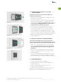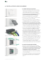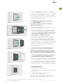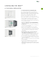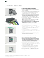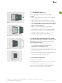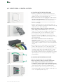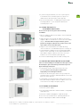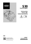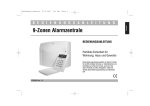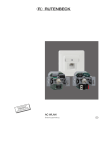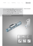
1
BEDIENUNGSANLEITUNG
DE
INSTRUCTION MANUAL
EN
INNOPAD IN-WALL-SYSTEMLÖSUNG
FÜR DAS IPAD 2™* UND „DAS NEUE“ IPAD™*
INNOPAD IN-WALL-SYSTEM SOLUTIONS
FOR IPAD 2™* AND „THE NEW“ IPAD™*
*Trademark notice: iPad™ is a trademark of Apple Inc., registered in the U.S. and other countries.
INNO
ZERTIFIZIERUNG NACH
05
This device complies with Part 15 of the FCC Rules. Operation is subject to the following two conditions:
(1) This device may not cause harmful interference, and (2) this device must accept any interference received,
including interference that may cause undesired operation.
This equipment has been tested and found to comply with the limits for a Class B digital device, pursuant to part 15
of the FCC rules. These limits are designed to provide reasonable protection against harmful interference in a residential
installation. This equipment generates, uses and can radiate radio frequency energy and, if not installed and used in
accordance with the instructions, may cause harmful interference to radio communications. However, there is no
guarantee that interference will not occur in a particular installation. If this equipment does cause harmful
interference to radio or television reception, which can be determined by turning the equipment off and on, the user
is encouraged to try to correct the interference by one or more of the following measures:
Reorient or relocate the receiving antenna
Increase the separation between the equipment and the receiver
Connect the equipment into an outlet on a circuit different from that to which the receiver is connected
Consult the dealer or an experienced radio/TV technician for help
2 | BEDIENUNGSANLEITUNG INNOPAD
INNO
INHALT
DE
Bitte lesen Sie vor der Montage und Inbetriebnahme des INNOPAD die Bedienungsanleitung
und beachten Sie unbedingt die Empfehlungen und Anweisungen.
1 SICHERHEITSHINWEISE
04
2 EINLEITUNG
04
3 LIEFERUMFANG
05
4 WICHTIGE BAUTEILE
06
5 INSTALLATIONSVORBEREITUNG
08
6 INSTALLATION DES INNOPAD
09
6.1 INSTALLATION IN EINE MASSIVWAND
09
6.2 INSTALLATION IN EINE HOHLWAND
12
7 GEWÄHRLEISTUNG
14
BEDIENUNGSANLEITUNG INNOPAD | 3
INNO
1 SICHERHEITSHINWEISE
Bitte befolgen Sie diese Sicherheitshinweise genau, um Gefahren und
Schäden für Menschen und Sachwerte auszuschließen.
Befolgen Sie die Anweisungen und Empfehlungen in der Bedienungsanleitung.
Alle elektrischen Installationsarbeiten sind von einem ausgebildeten Elektriker unter
Einhaltung der allgemeinen Vorschriften für elektrische Anschlüsse durchzuführen.
Stellen Sie vor der Installation des INNOPAD sicher, dass am Installationsort alle
stromführenden Kabel von der Spannungsversorgung getrennt sind!
Das INNOPAD ist für den Betrieb in folgenden Spannungsbereichen ausgelegt:
100 – 240 V AC; 50/60 Hz., 0,2 A. Wichtig: abgesichert durch 16 A Haussicherung!
Am Installationsort sollte direkte Sonneneinstrahlung vermieden und
Temperaturen von 0 – 35 °C sowie eine relative Luftfeuchtigkeit von 10 – 95 %
(nicht kondensierend) nicht unter- oder überschritten werden.
Schützen Sie das INNOPAD vor Nässe und Flüssigkeiten, um Beschädigungen zu verhindern.
Bei Beschädigung des INNOPAD durch äußere Krafteinwirkung oder Kontakt mit
Flüssigkeiten das Gerät sofort mit der vorgeschalteten Sicherung von der
Spannungsversorgung trennen.
Zur Säuberung des INNOPAD nur das mitgelieferte Reinigungstuch nutzen!
Bitte verwenden Sie keine aggressiven Reinigungsmittel.
Verwenden Sie dieses Produkt nur für die vom Hersteller ausdrücklich
vorgegebenen Apple* Geräte.
Bewahren Sie die Bedienungsanleitung zum späteren Gebrauch auf.
Der Hersteller haftet nicht für Schäden oder Verletzungen, die durch falsche Montage
oder unsachgemäße Verwendung verursacht werden.
Dieses Produkt enthält kleine Teile, die beim Verschlucken zum Erstickungstod
führen können. Lassen Sie die Teile nicht unbeaufsichtigt in der Nähe von Kindern liegen!
2 EINLEITUNG
INNO bietet für alle gängigen WLAN-basierten Haustechniksteuerungen die idealen
IN-WALL-SYSTEMLÖSUNGEN für das iPad™*. Als Teil einer kompletten Steuerungslösung
bieten die iPads™* eine Vielzahl praktischer und bedienerfreundlicher Applikationen, zum
Beispiel als Alternative zu bestehenden KNX-Schalterprogrammen.
INNOPAD steht für hochwertige IN-WALL-SYSTEMLÖSUNGEN aus edelsten Materialien, die
sich den verbauten Designideen ihrer Umgebung ohne Einschränkung anpassen. Mit
äußerst aufwendigen Verfahren verarbeitet INNO zum Beispiel kostbare Edelhölzer, Blattgold,
wertvolle Steine sowie hochwertigste Carbonfasern und Lacke zu Systemlösungen, die auf
anspruchsvollste Art Funktionalität mit Luxusdesign vereinen.
Um die Dekore einerseits dauerhaft zu schützen und andererseits die Brillanz der Optik
zu unterstreichen, werden sie durch ein Sandwichverfahren aus speziell gehärtetem Glas
geschützt. Ein besonderes Designelement ist der beleuchtete Bedien-Button, der auch in
der Dunkelheit Orientierung gibt.
Mit INNOPAD wird jedes iPad™* zum integrierten, kundenspezifischen Design-TouchpadController für moderne Multiroom-Systeme, private und gewerbliche Medientechnik,
Home-Entertainment und die Steuerung intelligenter Gebäudetechnik.
*Trademark notice: Apple and iPad™ are trademarks of Apple Inc., registered in the U.S. and other countries.
4 | BEDIENUNGSANLEITUNG INNOPAD
INNO
3 LIEFERUMFANG
DE
Bitte prüfen Sie den Inhalt der Verpackung auf Vollständigkeit, bevor Sie mit der Montage
beginnen. Die gelieferte Verpackung enthält folgende Bauteile:
Anzahl Bezeichnung
1
Installationsdose mit Netzteilplatine und vormontierten Hohlwandspreizen
1
Connectionboard
1
Metallträger
2
Distanzbleche für die iPad 2™* Installation
2
Magnetklebefolie
1
Glasdekorrahmen mit integriertem Home-Button und 6 Haltemagneten
5
Arretierungsschrauben M3 x 8 DIN 7500 Form C (für Metallträger)
3
Gewindeschrauben M3 x 8 DIN 7985 / ISO 7045
(zur Befestigung der Installationsdose an der Unterputzeinbaudose)
1
Zugentlastungsbügel (vormontiert)
1
Erdungskabel
1
Einbauschablone für den Hohlwandeinbau
1
Paar Montagehandschuhe
1
INNO Reinigungstuch
Bitte beachten Sie: Für den Einbau in festes Mauerwerk ist eine speziell zur
Aufnahme der Installationsdose gefertigte Unterputzeinbaudose optional erhältlich.
*Trademark notice: iPad™ is a trademark of Apple Inc., registered in the U.S. and other countries.
BEDIENUNGSANLEITUNG INNOPAD | 5
INNO
4 WICHTIGE BAUTEILE
4.1 INSTALLATIONSDOSE
2
4
BESONDERE MERKMALE
2
4
7
2
4
Mit Führungsvorrichtung zur
Aufnahme der Unterputzdose
(Pendelfunktion)
Auch für Hohlwandinstallationen
ausgelegt
6 Metallspreizen bieten sicheren
Halt in jeder Hohlwand
Kabeldurchführungen und
Zugentlastung für alle Kabeltypen
Polyamid 6 brandgeschützt (Pa 6 V0)
7
3
7
6
5
1
NETZTEIL /
SPANNUNGSVERSORGUNG
3
7
7
4
2
4
2
4
2
Maßeinheiten: [inch] & mm
1
Netzteilplatine
5
Führungsschiene Connectionboard
2
Befestigungsschrauben mit Hohlwandspreizen
6
Zugentlastung (Rückseite)
3
Ausbrechbare Kabeldurchführung
7
Aufnahme Arretierungsschrauben
4
Aussparungen zur Aufnahme des Metallträgers
Multinational einsetzbar
Kein externes Netzteil notwendig,
dadurch einfache Nachrüstbarkeit
im Bestandsbau
Input AC: 100 – 240 V, 0,2 A
Frequenz: 50 / 60 Hz
Output DC: 5 VDC (+)
4.2 METALLTRÄGER
5
5
3
3,6
6,1
5
4
239,35
3
2
3
1
190,2
188,6
185,9
4
4
4
3
3
4
7
4
3
5
5
5
10,85
12,525
221,55
Maßeinheiten: (inch) & mm
Aussparung für Einschub Connectionboard
4
Zentrierung für Glasdekorrahmen
2
Anschluss Erdungskabel (Rückseite)
5
Haftflächen für Magnethalterung
3
Aufnahme Arretierungsschrauben
1
*Trademark notice: iPad™ is a trademark of Apple Inc., registered in the U.S. and other countries.
6 | BEDIENUNGSANLEITUNG INNOPAD
BESONDERE MERKMALE
Magnetische Aufnahmefunktion
des iPad™*
Ausführung in Edelstahl
Seitliche Aufnahmeflächen zur
Zentrierung und Fixierung des
Glasdekorrahmens
4
INNO
DE
4.3 GLASDEKORRAHMEN
2
BESONDERE MERKMALE
2
2
Einzigartiger beleuchteter
Bedien-Button
Kabellose Kontaktierung,
einfache Installation
Integrierte Magnete zur Fixierung an
Metallträger
1
2
2
2
Maßeinheiten: [inch] & mm
1
Bedien-Button
2
Integrierte Magnete
4.4 UNTERPUTZEINBAUDOSE (OPTIONAL)
Nicht im Lieferumfang enthalten. Bei Bedarf unter der Art.-Nr.: INN PAD-UP-99-99-02-00.
BESONDERE MERKMALE
Speziell gefertigte Einbaudose
für den Massivwandeinbau
Mit seitlichen Rillen für den sicheren
Halt im eingeputzten Zustand
Die Unterputzdose bietet eine
Pendelaufnahme für die Installationsdose, um die perfekte Ausrichtung
zu gewährleisten
Kabeldurchführungen von allen Seiten
Polyamid 6 brandgeschützt (Pa 6 V0)
3
2
2
1
3
3
1
Ausbrechbare Kabeldurchführung
2
Fixierungslöcher
3
Arretierung für Installationsdose
Maßeinheiten: [inch] & mm
*Trademark notice: iPad™ is a trademark of Apple Inc., registered in the U.S. and other countries.
BEDIENUNGSANLEITUNG INNOPAD | 7
INNO
5 INSTALLATIONSVORBEREITUNG
5.1 WAHL DES INSTALLATIONSORTES
Für eine reibungslose Montage des INNOPAD und den problemlosen Betrieb des eingesetzten
iPad™* sind bei der Auswahl des Installationsortes folgende Faktoren zu beachten:
Es muss ein ausreichend starkes WiFi-Signal für den störungsfreien
Betrieb des iPad™* vorliegen.
Der Installationsort muss eine Bautiefe von mindestens 56 mm für den
Unterputzeinbau und mindestens 45 mm für den Hohlwandeinbau ermöglichen.
Tipp: Nutzen Sie für die Montage in einer Massivwand die speziell gefertigte
Unterputzeinbaudose für das INNOPAD. Sie ist nicht im Lieferumfang enthalten
und kann gesondert bestellt werden (Art.-Nr.: INN PAD-UP-99-99-02-00).
Am Installationsort sollte direkte Sonneneinstrahlung vermieden und
Temperaturen von 0 – 35 °C sowie eine relative Luftfeuchtigkeit von 10 – 95 %
(nicht kondensierend) nicht unter- oder überschritten werden.
Am Installationsort muss für eine ausreichende Spannungsversorgung
(gemäß Angaben) gesorgt werden.
Für den Unterputzeinbau sollte der Installationsort in der Wand frei von Kabeln,
Versorgungsleitungen oder Stützträgern sein.
Die Installationshöhe sollte eine einfache Bedienung des iPad™* für alle Nutzer ermöglichen.
Bitte beachten Sie: Alle elektrischen Verbindungen und Installationsarbeiten müssen von
ausgebildeten Elektrikern unter Einhaltung der allgemeinen Regeln und Vorschriften für
elektrische Anschlüsse ausgeführt werden.
5.2 AUSPACKEN DER BAUTEILE
Die kompakte Verpackung des INNOPAD schützt die Einzelteile vor Beschädigung und Verschmutzung. Für den optimalen Schutz der hochwertigen Bauteile mit empfindlichen Oberflächen
wurde die Umverpackung so konzipiert, dass die einzelnen Teile in der Reihenfolge ihrer
Montage nacheinander aus den schützenden Fächern herausgenommen werden können.
Bitte beachten Sie, vor Entnahme der Bauteile die Transportsicherung zu entfernen
(gekennzeichnet durch den Aufkleber auf dem Metallträger).
Um Beschädigungen zu vermeiden, behandeln Sie bitte jedes Teil mit Vorsicht und nutzen
Sie zur Installation die mitgelieferten Montagehandschuhe.
*Trademark notice: iPad™ is a trademark of Apple Inc., registered in the U.S. and other countries.
8 | BEDIENUNGSANLEITUNG INNOPAD
INNO
6 INSTALLATION DES INNOPAD
DE
6.1 INSTALLATION IN EINE MASSIVWAND
6.1.1 INSTALLATION DER UNTERPUTZEINBAUDOSE
Für einen passgenauen Einbau des INNOPAD in eine Massivwand empfehlen wir die Verwendung der INNO Unterputzeinbaudose (UP-Dose). Sie ist speziell für die Aufnahme der
INNOPAD Installationsdose ausgelegt und garantiert einen
exakten und sicheren Sitz der kompletten INNO IN-WALLSYSTEMLÖSUNG.
Abbildung 1
Die UP-Dose ist nicht im Lieferumfang enthalten und kann
optional bestellt werden (Art.-Nr. INN PAD-UP-99-99-02-00).
1. Entnehmen Sie die Einbauschablone für den Unterputzeinbau
aus der Verpackung und richten Sie diese waagerecht am
Installationsort aus.
2. Befestigen Sie die Schablone mit einem Klebeband an der
Wand und zeichnen Sie die inneren Umrisse der Vorlage mit
einem Stift nach (Abb. 1).
3. Nehmen Sie die Schablone von der Wand ab und stellen Sie
sicher, dass am gewünschten Installationsort die Wand frei
von Versorgungsleitungen oder Metallträgern ist.
Abbildung 2
4. Entfernen Sie im markierten Wandbereich vorsichtig den
Ausbruch für die Aufnahme der UP-Dose.
5. Entnehmen Sie die UP-Dose aus der Verpackung.
6. Halten Sie die UP-Dose unter Beachtung des im Dosenboden befindlichen Ausrichtungshinweises „TOP“ an die
Wandöffnung und bestimmen Sie die optimale Position für
die Durchführung des Stromkabels in die UP-Dose (Abb. 2).
Abbildung 3
7. Stellen Sie sicher, dass am Installationsort alle stromführenden Kabel von der Spannungsversorgung getrennt sind!
Öffnen Sie an passender Stelle die ausbrechbare Kabeldurchführung und ziehen Sie das Stromkabel und ggf. benötigte
Audiokabel durch die Kabeldurchführung in die UP-Dose
ein. Achten Sie darauf, die Kabel nicht zu beschädigen.
8. Setzen Sie die UP-Dose lotrecht mit der „TOP“-Markierung
nach oben in die Wandöffnung ein und fixieren Sie die UP-Dose
in der Wand (Abb. 3). Tipp: Nutzen Sie zur Befestigung die
Fixierungslöcher im Boden der UP-Dose.
9. Zur endgültigen Arretierung der UP-Dose muss sie bündig
eingegipst werden. Verputzen Sie die Kanten der UP-Dose
flächig zur Wand.
BEDIENUNGSANLEITUNG INNOPAD | 9
INNO
6.1 INSTALLATION IN EINE MASSIVWAND
6.1.2 EINBAU DER INSTALLATIONSDOSE
1. Entnehmen Sie nach Entfernung der Transportsicherung
die Installationsdose aus der Verpackung.
2. Halten Sie die Installationsdose unter Beachtung des im
Dosenboden befindlichen Ausrichtungshinweises „TOP“ an
die UP-Dose an und öffnen Sie die Kabeldurchführung.
Abbildung 4
3. Stellen Sie sicher, dass am Installationsort alle stromführenden Kabel von der Spannungsversorgung getrennt sind!
Ziehen Sie das Stromkabel und ein ggf. benötigtes Audiokabel durch die Kabeldurchführung in die Installationsdose
ein. Achten Sie darauf, die Kabel nicht zu beschädigen.
4. Sichern Sie das Stromkabel mit der Zugentlastung auf der
Rückseite der Installationsdose (Abb. 4). Tipp: Durch Umdrehen des Zugentlastungsbügels kann die Zugentlastung
auf unterschiedliche Kabelstärken abgestimmt werden.
Abbildung 5
5. Alle elektrischen Installationsarbeiten sind von ausgebildeten Elektrikern fachgerecht durchzuführen. Kürzen Sie
das Stromkabel auf eine Länge von 250 mm ab Zugentlastung und befestigen Sie es unter Berücksichtigung der
Anschlussbeschriftung am vormontierten Netzteil (Abb. 5).
6. Alle elektrischen Installationsarbeiten sind von ausgebildeten Elektrikern fachgerecht durchzuführen. Für eine
Tonausgabe über Chinchkabel (NF) befestigen Sie das
Audiokabel am Audioausgang der Hauptplatine (Abb. 5).
7. Setzen Sie die Installationsdose mit der „TOP“-Markierung
nach oben in die UP-Dose ein und fixieren Sie diese mit
Hilfe der Gewindeschrauben an der UP-Dose.
Abbildung 6
8. Richten Sie mit Hilfe der Pendelaufnahme die Installationsdose lotrecht aus und sichern Sie die Position durch Festziehen der Gewindeschrauben (Abb. 6).
6.1.3 INSTALLATION DES METALLTRÄGERS
1. Entnehmen Sie den Metallträger aus der Verpackung.
Abbildung 7
2. Stellen Sie sicher, dass am Installationsort alle stromführenden Kabel von der Spannungsversorgung getrennt sind!
Alle elektrischen Installationsarbeiten sind von ausgebildeten Elektrikern fachgerecht durchzuführen.
Zur Erdung des Metallträgers befestigen Sie das Erdungskabel an dem dafür vorgesehenen Anschluss auf der
Rückseite des Metallträgers.
3. Setzen Sie den Metallträger passend in die Aussparung der
Installationsdose ein und fixieren Sie ihn mit der mittleren
Arretierungsschraube an den vorgesehenen Aufnahmen
(Abb. 7).
4. Falls Sie ein iPad 2™* nutzen, setzen Sie – für einen perfekten
Sitz unter dem Glasdekorrahmen – die mitgelieferten
2 Distanzbleche in den Boden des Metallträgers ein (Abb. 8).
Abbildung 8
5. Befestigen Sie den Metallträger – bei iPad 2™* Nutzung
inklusive Distanzbleche – mit den restlichen Arretierungsschrauben an der Installationsdose.
*Trademark notice: iPad™ is a trademark of Apple Inc., registered in the U.S. and other countries.
10 | BEDIENUNGSANLEITUNG INNOPAD
INNO
DE
6.1.4 BEFESTIGUNG DES IPAD™*/** AUF DEM
METALLTRÄGER
Bitte benutzen Sie bei der Installation des INNOPAD die
mitgelieferten Handschuhe.
1. Entnehmen Sie die Magnetklebefolien und das Connectionboard aus der Verpackung.
Abbildung 9
2. Lösen Sie die Schutzfolie von der Klebefläche der Magnetklebefolien und befestigen Sie sie auf der Rückseite des
iPad™* (Abb. 9). Achtung: Bei Nutzung des iPad 2™* positionieren Sie bitte die Magnetklebefolien so, dass sie auf
den Distanzblechen am Metallträger haften.
3. Stecken Sie das Connectionboard mit der Platine nach
hinten zeigend in den iPad™* Dockanschluss (Abb. 9).
4. Schieben Sie das iPad™* vorsichtig mit der Platine des
Connectionboards voraus bündig in die Führungsschiene
der Installationsdose, so dass die Magnetklebefolien auf der
Rückseite des iPad™* auf dem Metallträger haften (Abb. 10).
Abbildung 10
5. Säubern Sie das iPad™* Display mit dem beigefügten
INNO Reinigungstuch.
6.1.5 INSTALLATION DES GLASDEKORRAHMENS
Vorsicht bei der Handhabung des wertvollen Glasdekorrahmens. Um eine Körper- und Sachbeschädigung zu verhindern, den Glasrahmen bei der Installation nicht fallen lassen.
Abbildung 11
1. Entnehmen Sie den Glasdekorrahmen vorsichtig aus der
Verpackung. Bitte benutzen Sie zum Schutz der hochwertigen Oberflächen bei der Installation die mitgelieferten
Handschuhe.
2. Positionieren Sie den Glasdekorrahmen, mit dem INNO
Logo im unteren Rahmenbereich lesbar, genau vor den
Metallträger (Abb. 11).
3. Setzen Sie den Glasdekorrahmen entlang der Zentrierhilfe
vorsichtig auf den Metallträger, bis die Magneten auf der
Rückseite des Rahmens fest auf dem Träger haften (Abb. 12).
6.1.6 INBETRIEBNAHME
Abbildung 12
1. Schalten Sie die Spannungsversorgung ein.
2. Der Home-Button leuchtet, das iPad™* wird geladen
und ist betriebsbereit.
3. Schalten Sie das iPad™* ein und nehmen Sie die
gewünschten Einstellungen vor.
Bei Fragen zur Bedienung des iPad™* und der installierten
Apps nutzen Sie bitte die Handbücher der Hersteller.
*Trademark notice: iPad™ is a trademark of Apple Inc., registered in the U.S. and other countries.
**Nicht im Lieferumfang enthalten.
BEDIENUNGSANLEITUNG INNOPAD | 11
INNO
6.2 INSTALLATION IN EINE HOHLWAND
6.2.1 EINBAU DER INSTALLATIONSDOSE
1. Entnehmen Sie die Einbauschablone für den Hohlwandeinbau aus der Verpackung, richten Sie diese am Installationsort waagerecht aus und zeichnen Sie die inneren
Umrisse der Schablone mit einem Stift nach (Abb. 13).
Abbildung 13
2. Stellen Sie sicher, dass am Installationsort die Wand frei
von Versorgungsleitungen oder Metallträgern ist.
Entfernen Sie im markierten Bereich vorsichtig den
Ausschnitt für die Aufnahme der Installationsdose.
3. Entnehmen Sie nach Entfernung der Transportsicherung
die Installationsdose aus der Verpackung.
4. Halten Sie die Installationsdose unter Beachtung des im
Dosenboden befindlichen Ausrichtungshinweises „TOP“ an
die Wandöffnung und öffnen Sie die Kabeldurchführung.
Abbildung 14
5. Stellen Sie sicher, dass am Installationsort alle stromführenden Kabel von der Spannungsversorgung getrennt sind!
Ziehen Sie das Stromkabel und ein ggf. benötigtes Audiokabel durch die Kabeldurchführung in die Installationsdose
ein. Achten Sie darauf, die Kabel nicht zu beschädigen.
6. Sichern Sie das Stromkabel mit der Zugentlastung auf der
Rückseite der Installationsdose. Tipp: Durch Umdrehen
des Zugentlastungsbügels kann die Zugentlastung auf
unterschiedliche Kabelstärken abgestimmt werden (Abb. 14).
7. Alle elektrischen Installationsarbeiten sind von ausgebildeten Elektrikern fachgerecht durchzuführen. Kürzen Sie
das Kabel auf eine Länge von 250 mm ab Zugentlastung und
befestigen Sie es unter Berücksichtigung der Anschlussbeschriftung am vormontierten Netzteil (Abb. 15).
Abbildung 15
8. Für eine Tonausgabe über Chinchkabel (NF) befestigen Sie
das Audiokabel am Audioausgang der Hauptplatine (Abb. 15).
9. Setzen Sie die Installationsdose mit der „TOP“-Markierung
nach oben in die Wandöffnung und fixieren Sie sie lotrecht
durch Schrauben der Metallspreizen bis zum Auftreten
eines Widerstandes (Abb. 16). Die Spreizen klappen
automatisch beim Schrauben aus, kontern von innen gegen
die Hohlraumwand und befestigen so die Installationsdose.
6.2.2 INSTALLATION DES METALLTRÄGERS
Abbildung 16
1. Entnehmen Sie den Metallträger aus der Verpackung.
2. Stellen Sie sicher, dass am Installationsort alle stromführenden Kabel von der Spannungsversorgung getrennt sind!
Alle elektrischen Installationsarbeiten sind von ausgebildeten Elektrikern fachgerecht durchzuführen.
Zur Erdung des Metallträgers befestigen Sie das Erdungskabel an dem dafür vorgesehenen Anschluss auf der Rückseite des Metallträgers.
Abbildung 17
12 | BEDIENUNGSANLEITUNG INNOPAD
3. Setzen Sie den Metallträger passend in die Aussparung der
Installationsdose ein und fixieren Sie ihn mit der mittleren
Arretierungsschraube an den vorgesehenen Aufnahmen
(Abb. 17).
INNO
DE
4. Falls Sie ein iPad 2™* nutzen, setzen Sie – für einen perfekten Sitz unter dem Glasdekorrahmen – die mitgelieferten
2 Distanzbleche in den Boden des Metallträgers ein (Abb. 18).
5. Befestigen Sie den Metallträger – bei iPad 2™* Nutzung
inklusive Distanzblechen – mit den restlichen Arretierungsschrauben an der Installationsdose.
Abbildung 18
6.2.3 BEFESTIGUNG DES IPAD™*/** AUF DEM
METALLTRÄGER
Bitte benutzen Sie bei der Installation des INNOPAD die
mitgelieferten Handschuhe.
1. Entnehmen Sie die Magnetklebefolien und das Connectionboard aus der Verpackung.
2. Lösen Sie die Schutzfolie von der Klebefläche der Magnetklebefolien und befestigen Sie sie auf der Rückseite des
iPad™* (Abb. 19). Achtung: Bei Nutzung des iPad 2™* positionieren Sie bitte die Magnetklebefolien so, dass sie auf
den Distanzblechen am Metallträger haften.
Abbildung 19
3. Stecken Sie das Connectionboard mit der Platine nach
hinten zeigend in den iPad™* Dockanschluss (Abb. 19).
4. Schieben Sie das iPad™* vorsichtig mit der Platine des
Connectionboards voraus bündig in die Führungsschiene
der Installationsdose, so dass die Magnetklebefolien auf der
Rückseite des iPad™* auf dem Metallträger haften (Abb. 20).
5. Säubern Sie das iPad™* Display mit dem beigefügten
INNO Reinigungstuch.
Abbildung 20
6.2.4 INSTALLATION DES GLASDEKORRAHMENS
Vorsicht bei der Handhabung des wertvollen Glasdekorrahmens. Um eine Körper- und Sachbeschädigung zu verhindern, den Glasrahmen bei der Installation nicht fallen lassen.
1. Entnehmen Sie den Glasdekorrahmen vorsichtig aus der
Verpackung. Bitte benutzen Sie zum Schutz der hochwertigen Oberflächen die mitgelieferten Handschuhe.
2. Positionieren Sie den Glasdekorrahmen, mit dem INNO Logo
im unteren Rahmenbereich, vor den Metallträger (Abb. 21).
Abbildung 21
3. Setzen Sie den Glasdekorrahmen entlang der Zentrierhilfe
vorsichtig auf den Metallträger, bis die Magneten auf der
Rückseite des Rahmens fest auf dem Träger haften (Abb. 22).
6.2.5 INBETRIEBNAHME
1. Schalten Sie die Stromversorgung ein.
2. Der Home-Button leuchtet, das iPad™* wird geladen und ist
betriebsbereit.
3. Schalten Sie das iPad™* ein und nehmen Sie die
gewünschten Einstellungen vor.
Abbildung 22
Bei Fragen zur Bedienung des iPad™* und der installierten
Apps nutzen Sie bitte die Handbücher der Hersteller.
*Trademark notice: iPad™ is a trademark of Apple Inc., registered in the U.S. and other countries.
**Nicht im Lieferumfang enthalten.
BEDIENUNGSANLEITUNG INNOPAD | 13
INNO
7 GEWÄHRLEISTUNG
GEWÄHRLEISTUNG
Ab Kaufdatum beträgt die Gewährleistungsfrist 2 Jahre. Ausnahme: Das INNOPAD wurde im
Rahmen der Gewährleistung repariert oder ersetzt. Die Gewährleistung gilt in diesem Fall
bis zum Ende der ursprünglichen Gewährleistungsfrist oder 6 Monate ab Reparatur- bzw.
Austauschdatum.
MANGELANSPRÜCHE / MANGELVALIDIERUNG
Bei Funktionsstörung Ihres INNOPAD wenden Sie sich bitte mit Originalrechnung und Angabe
der Seriennummer sowie der Fehlerbeschreibung an Ihren Händler. Nach einer vom
Hersteller oder dessen autorisierten Kundendienstes vorgenommenen Funktionsprüfung
wird festgestellt, ob der Defekt aufgrund von Material- oder Verarbeitungsmängeln innerhalb
der Gewährleistungsfrist aufgetreten ist und somit ein Anspruch auf Reparatur oder
Austausch Ihres INNOPAD entstanden ist.
GEWÄHRLEISTUNGSAUSSCHLUSS
Die folgenden Schäden sind von der Gewährleistung ausgenommen. Schäden verursacht durch:
Missbrauch sowie Nichteinhaltung der Bedienungsanleitung;
unsachgemäßes Bedienen;
Änderung des INNOPAD über die in der Bedienungsanleitung beschriebenen Merkmale;
Reparaturversuche oder Reparatur durch eine nicht autorisierte Person;
Nutzung des INNOPAD in Verbindung mit Fremdprodukten;
Geräte, bei denen die Hersteller-Seriennummer gelöscht, entfernt, verändert oder
unleserlich gemacht wurde;
Anschluss an eine nicht geeignete Spannungsversorgung;
höhere Gewalt.
HAFTUNGSBESCHRÄNKUNG
Die oben abgeführte Gewährleistung umfasst das volle Ausmaß der Haftung der
INNO International GmbH. Daher lehnt die INNO International GmbH alle weiteren Haftungsansprüche für Verluste oder Schäden (mit Ausnahme nachgewiesener grober Fahrlässigkeit)
aus dem Erwerb, Besitz, Verkauf oder Nutzung des INNOPAD ab.
In keinem Fall ist die INNO International GmbH haftbar für Folgeschäden, Verzögerungen,
unzutreffende Auskünfte oder Ratschläge und Verletzungen des Urheberrechts.
Mängelbezogene Rechte des Käufers sind nicht betroffen.
VERSCHIEDENE BESTIMMUNGEN
Keine Person, eingeschlossen alle Vertriebspartner, Händler, Agenten oder Vertreter, ist
berechtigt, im Namen der INNO International GmbH eine Gewährleistung zu übernehmen
bzw. die Gewährleistungsansprüche abzuändern. Der Käufer muss eigenständig die Eignung
des INNOPAD für den geplanten Verwendungszweck bestimmen.
Offene Fragen beantwortet unsere Hotline unter +49 (0) 180 501 501 3
(14 Cent / Min. aus dem dt. Festnetz, max. 42 Cent / Min. aus Mobilfunknetzen.
Bei Anrufen aus dem Ausland können abhängig vom Netzbetreiber zusätzliche
Kosten anfallen.)
PADPAD
14 | BEDIENUNGSANLEITUNG
INSTRUCTION MANUAL INNO
INNO
INNO International GmbH
Heinrich-Hertz-Straße 12
59423 Unna / Germany
Phone +49 (0) 2303 333 · 333
www.inno-international.com
INNO
INSTRUCTION MANUAL
INNOPAD IN-WALL-SYSTEM SOLUTIONS
FOR IPAD 2™* AND „THE NEW“ IPAD™*
*Trademark notice: iPad™ is a trademark of Apple Inc., registered in the U.S. and other countries.
BEDIENUNGSANLEITUNG
INSTRUCTION MANUAL INNOPAD | 15
EN
INNO
CERTIFIED PURSUANT TO
05
This device complies with Part 15 of the FCC Rules. Operation is subject to the following two conditions:
(1) This device may not cause harmful interference, and (2) this device must accept any interference received,
including interference that may cause undesired operation.
This equipment has been tested and found to comply with the limits for a Class B digital device, pursuant to part 15
of the FCC rules. These limits are designed to provide reasonable protection against harmful interference in a residential
installation. This equipment generates, uses and can radiate radio frequency energy and, if not installed and used in
accordance with the instructions, may cause harmful interference to radio communications. However, there is no
guarantee that interference will not occur in a particular installation. If this equipment does cause harmful
interference to radio or television reception, which can be determined by turning the equipment off and on, the
user is encouraged to try to correct the interference by one or more of the following measures:
Reorient or relocate the receiving antenna
Increase the separation between the equipment and the receiver
Connect the equipment into an outlet on a circuit different from that to which the receiver is connected
Consult the dealer or an experienced radio / TV technician for help
16 | INSTRUCTION MANUAL INNOPAD
INNO
CONTENTS
Please read the operating manual before assembling and using the INNOPAD and follow all
recommendations and instructions.
1 SAFETY NOTICES
18
2 INTRODUCTION
18
3 SCOPE OF DELIVERY
19
4 KEY COMPONENTS
20
5 PREPARING FOR INSTALLATION
22
6 INSTALLING THE INNOPAD
23
6.1 SOLID WALL INSTALLATION
23
6.2 CAVITY WALL INSTALLATION
26
7 WARRANTY
28
INSTRUCTION MANUAL INNOPAD | 17
EN
INNO
1 SAFETY NOTICES
Please follow these safety notices carefully to prevent hazards and danger
to humans and property.
Follow all instructions and recommendations in the operating manual.
All electrical installation work must carried out by a qualified electrician in compliance
with the general regulations for electrical connections.
Ensure prior to installing the INNOPAD that all live cables at the installation site are
disconnected from the power supply!
The INNOPAD is designed to be used with the following voltage: 100 – 240 V AC;
50 / 60 Hz, 0.2 A. Important: Use a 16 A household fuse!
The installation site should not be exposed to direct sunlight and maintain temperatures
between 0 °C and 35 °C and a relative humidity between 10 % and 95 % (no condensation).
Protect the INNOPAD from damp and liquids to prevent it from getting damaged.
If the INNOPAD is damaged due to external force or contact with liquids, immediately
disconnect the device from the power supply by using the fuse.
Use only the cleaning cloth delivered with the INNOPAD to clean the device!
Please do not use any aggressive detergents.
This product should only be used with the Apple* devices specifically stated
by the manufacturer.
Keep the operating manual for later use.
The manufacturer does not assume liability for any damages or injuries caused by
incorrect installation or inappropriate use.
This product contains small parts that may lead to death from suffocation if swallowed.
Do not leave these parts unsupervised where children can reach them!
2 INTRODUCTION
INNO provides ideal iPad™* IN-WALL-SYSTEM SOLUTIONS for all common WLAN-based
utility management systems. As part of an all-in-one management solution, iPads™* offer
numerous practical and user-friendly applications, as an alternative to existing KNX switch
ranges, for instance.
INNOPAD stands for high-quality IN-WALL-SYSTEM SOLUTIONS made from sophisticated
materials that adapt seamlessly to any existing interior designs. INNO’s production
processes are complex. Rare exotic woods, leaf gold, precious stones and state-of-the-art
carbon fibres and lacquers are transformed into system solutions that combine the highest
standard of functionality with luxury designs.
To permanently protect the decors and at the same time emphasise their glossy appearance,
they are protected with a sandwich method that uses specially hardened glass.
The illuminated operating button, which also offers a means of orientation in the dark,
is one of the key design features.
INNOPAD makes every iPad™* into an integrated customer-specific design touchpad
controller for modern multi-room systems, private and commercial media technology,
home entertainment and intelligent utility management.
*Trademark notice: Apple and iPad™ are trademarks of Apple Inc., registered in the U.S. and other countries.
18 | INSTRUCTION MANUAL INNOPAD
INNO
3 SCOPE OF DELIVERY
Please check the content of the package to ensure that you have all parts before starting the
installation. The package contains the following components:
No.
Description
1
Installation box with power supply board and pre-assembled cavity wall spreaders
1
Connection board
1
Metal base plate
2
Spacer plates for iPad 2™* installation
2
Magnetic adhesive foils
1
Decorative glass frame with integrated home button and 6 magnetic holders
5
M3 x 8 DIN 7500 form C stop screws (for metal base plate)
3
M3 x 8 DIN 7985 / ISO 7045 bolts
(for fixing the installation box to the flush-mounting box)
1
Tension relief lever (pre-assembled)
1
Earth cable
1
Template for cavity wall installations
1
Pair of protective gloves
1
INNO cleaning cloth
Please note: A flush-mounting box specially designed to hold the installation box is available
as an option extra for solid wall installations.
*Trademark notice: iPad™ is a trademark of Apple Inc., registered in the U.S. and other countries.
INSTRUCTION MANUAL INNOPAD | 19
EN
INNO
4 KEY COMPONENTS
4.1 INSTALLATION BOX
2
4
SPECIAL FEATURES
2
4
7
2
4
With guiding mechanism for
inserting the flush-mounting box
(movable inside)
Also designed for cavity wall
installations
6 metal spreaders provide secure hold
in any cavity wall
Cable feedthroughs and tension reliefs
for all cable types
Fireproof polyamide 6 (Pa 6 V0)
7
3
7
6
5
1
3
MAINS ADAPTER /
POWER SUPPLY
7
7
4
2
4
2
4
2
Dimensions: [inch] & mm
1
Power supply board
5
Connection board guide
2
Fixing screws with cavity wall spreaders
6
Tension relief (rear)
3
Cable feedthrough (can be broken out)
7
Stop screw holders
4
Recesses for inserting the metal base plate
Multi-national use
No external mains adapter necessary,
making it easy to install in existing
constructions
Input AC: 100 V to 240 V, 0.2 A
Frequency: 50 Hz / 60 Hz
Output DC: 5 VDC (+)
4.2 METAL BASE PLATE
5
5
3
3,6
6,1
5
4
239,35
3
2
3
1
190,2
188,6
185,9
4
4
4
3
3
4
7
4
3
5
5
5
10,85
12,525
221,55
Dimensions: mm
Recess for inserting connection board
4
Decorative glass frame alignment
2
Earth cable connection (rear)
5
Adhesive areas for magnetic holder
3
Stop screw holders
1
*Trademark notice: iPad™ is a trademark of Apple Inc., registered in the U.S. and other countries.
20 | INSTRUCTION MANUAL INNOPAD
SPECIAL FEATURES
Magnetic iPad™* holder function
Stainless steel design
Areas for aligning and fixing the
decorative glass frame (on the sides)
4
INNO
4.3 DECORATIVE GLASS FRAME
EN
2
SPECIAL FEATURES
2
2
Unique illuminated operating button
Wireless setup, easy installation
Integrated magnets for fixing to
metal base plate
1
2
2
2
Dimensions: [inch] & mm
1
Operating button
2
Integrated magnets (rear)
4.4 FLUSH-MOUNTING BOX (OPTIONAL)
Not included in the scope of delivery. Can be ordered under product number: INN PAD-UP-99-99-02-00.
SPECIAL FEATURES
Installation box specially designed for
solid wall installations
Has grooved sides for secure hold
when inserted in plaster
The flush-mounting box has a movable
inside so that the installation box can
be perfectly aligned
Cable feedthrough on all sides
Fireproof polyamide 6 (Pa 6 V0)
3
2
2
1
3
3
1
Cable feedthrough (can be broken out)
2
Fixing holes
3
Installation box retainer
Dimensions: [inch] & mm
*Trademark notice: iPad™ is a trademark of Apple Inc., registered in the U.S. and other countries.
INSTRUCTION MANUAL INNOPAD | 21
INNO
5 PREPARING FOR INSTALLATION
5.1 CHOOSING THE INSTALLATION SITE
The following factors must be considered when choosing the installation site so as to ensure
that the INNOPAD can be easily installed and the iPad™* operated without problems:
A sufficiently strong WiFi signal must be available in the area for the iPad™*
to operate correctly.
At the installation site, it must be possible to go 56 mm into a solid wall or 45 mm into a
cavity wall. Tip: Use the specially designed INNOPAD flush-mounting box for solid wall
installations. This item is not included in the scope of delivery but can be ordered
separately (product number: INN PAD-UP-99-99-02-00).
The installation site should not be exposed to direct sunlight and maintain temperatures
between 0 °C and 35 °C and a relative humidity between 10 % and 95 % (no condensation).
A sufficient power supply (according to specifications) has to be available at the
installation site.
When installing the device in a solid wall, the area should be free of cables, supply
pipes and supporting struts.
Please note: All electrical connections and installations must be carried out by a qualified
electrician in compliance with the general rules and regulations for electrical connections.
5.2 UNPACKING THE COMPONENTS
The compact INNOPAD packaging protects the individual components against damage and soiling.
To optimally protect the high-quality parts with easily damaged surfaces, the outer packaging is
designed so that the individual parts can be unpacked from their protective compartments one
by one in the order of assembly.
Please remember to remove the transport lock (marked by the sticker on the metal base plate)
before removing the components.
To avoid any damage, please handle each part with care and use the protective gloves during
installation that are provided for this purpose.
*Trademark notice: iPad™ is a trademark of Apple Inc., registered in the U.S. and other countries.
22 | INSTRUCTION MANUAL INNOPAD
INNO
6 INSTALLING THE INNOPAD
6.1 SOLID WALL INSTALLATION
EN
6.1.1 INSTALLING THE FLUSH-MOUNTING BOX
We recommend using the INNO flush-mounting box for
perfectly fitting the INNOPAD into a solid wall. It is specially
designed to accommodate the INNOPAD installation box and guarantees that the complete INNO IN-WALL-SYSTEM
SOLUTION is perfectly aligned and seated securely.
This item is not included in the scope of delivery but can be
ordered separately (product number: INN PAD-UP-99-99-02-00).
Figure 1
1. Take the template for solid wall installations from the
packaging and set it up horizontally at the installation site.
2. Fix the template to the wall with adhesive tape and trace the
inner lines with a pen (Fig. 1).
3. Remove the template from the wall and ensure that the
wall is free of supply pipes, cables and metal struts at the
installation site.
4. Carefully remove the area of wall within the markings so as
to insert the flush-mounting box.
5. Remove the flush-mounting box from the packaging.
Figure 2
6. Hold the flush-mounting box to the wall, taking care that
the „TOP“ marking at the bottom of the box is facing up, and
find the optimal position for feeding the power cable into
the box (Fig. 2).
7. Ensure that all live cables are disconnected from the
power supply at the installation site! Break out the
corresponding cable feedthrough and feed the power cable
and, if necessary, audio wire through the opening into the
flush-mounting box. Take care not to damage the cables.
Figure 3
8. Insert the flush-mounting box perpendicularly into the wall
recess, ensuring that the „TOP“ marking is facing up, and fix
the box to the wall (Fig. 3).
Tip: Use the fixing holes in the bottom of the flush-mounting
box for this purpose.
9. To fix the flush-mounting box in place, plaster must be
applied around it so that it fits smoothly into the wall.
Apply the plaster to all sides of the box so that there are no
protruding parts and wipe away all excess plaster to provide
a flush finish.
INSTRUCTION MANUAL INNOPAD | 23
INNO
6.1 SOLID WALL INSTALLATION
6.1.2 INSTALLING THE INSTALLATION BOX
1. Remove the transport lock then take the installation box
out of its packaging.
2. Hold the installation box to the flush-mounting box, taking
care that the „TOP“ marking at the bottom of the box is
facing up, and break out the cable feedthrough.
Figure 4
3. Ensure that all live cables are disconnected from the power supply at the installation site! Feed the power cable
and, if necessary, audio wire through the opening into the
installation box. Take care not to damage the cables.
4. Secure the power cable to the rear of the installation box
with the tension relief (Fig. 4).
Tip: The tension relief can be adjusted for various cable
diameters by rotating the tension relief lever.
Figure 5
5. All electrical installations must be carried out by a qualified electrician. Cut the power cable to a length of
250 mm from the tension relief and attach it to the preassembled mains supply in compliance with the connection
regulations (Fig. 5).
6. All electrical installations must be carried out by a
qualified electrician. Fix the audio wire to the audio output
on the main board to feed the audio signal out via cinch
cable (NF) (Fig. 5).
7. Insert the installation box in the flush-mounting box,
ensuring that the „TOP“ marking is facing up, and fix it with
the bolts.
Figure 6
8. Adjust the installation box perpendicularly with the help of
the movable inside of the flush-mounting box and fix it in
position by tightening the bolts (Fig. 6).
6.1.3 INSTALLING THE METAL BASE PLATE
1. Take the metal base plate out of the packaging.
2. Ensure that all live cables are disconnected from the power supply at the installation site! All electrical installations must be carried out by a qualified electrician.
To earth the metal base plate, connect the earth cable to the
earth connection on the rear of the metal base plate.
Figure 7
3. Fit the metal base plate correctly into the recesses in the
installation box and fix it with the medium-sized stop screw
to the corresponding holders (Fig. 7).
4. If you are using an iPad 2™*, insert the 2 spacer plates
in the bottom of the metal base plate for a perfect fit
underneath the decorative glass frame (Fig. 8).
5. Fix the metal base plate − including spacer plates when
installing iPad 2™* − to the installation box with the
remaining stop screws.
Figure 8
*Trademark notice: iPad™ is a trademark of Apple Inc., registered in the U.S. and other countries.
24 | INSTRUCTION MANUAL INNOPAD
INNO
6.1.4 FIXING THE IPAD™*/**
TO THE METAL BASE PLATE
Please wear the protective gloves when installing
the INNOPAD.
1. Take the magnetic adhesive foil and the connection board
from the packaging.
Figure 9
2. Unpeel the protective foil from the adhesive area of the
magnetic adhesive foil and stick it to the rear of the iPad™*
(Fig. 9). Attention: When using the iPad 2™*, please position the magnetic adhesive foil so that it sticks to the spacer
plates on the metal base plate.
3. Plug the connection board into the iPad™* docking
connector with the circuit board facing to the rear (Fig. 9).
4. Carefully push the iPad™* into the installation box guide
with the connection board circuit facing forward until it is
flush and the magnetic adhesive foil on the rear of the
iPad™* sticks to the metal base plate (Fig. 10).
5. Clean the iPad™* display with the INNO cleaning cloth.
Figure 10
6.1.5 INSTALLING THE DECORATIVE GLASS FRAME
Take care when handling the valuable decorative glass frame.
Do not drop the glass frame during installation to prevent
physical damage and injuries.
1. Carefully take the decorative glass frame out of the
packaging. Please wear the gloves to protect the
high-quality surface during installation.
Figure 11
2. Position the decorative glass frame exactly on top of the
metal base plate so that the INNO logo appears in the lower
part of the frame (Fig. 11).
3. Carefully place the decorative glass frame onto the metal
base plate along the adjuster until the magnets on the rear
of the frame stick solidly to the plate (Fig. 12).
6.1.6 TURNING ON THE DEVICE
1. Turn on the power supply.
Figure 12
2. The home button illuminates and the Pad™* is charged up
and ready to use.
3. Turn on the iPad™* and apply the required settings.
Please refer to the manufacturers‘ operating manuals for
details on operating the iPad™* and installed apps.
*Trademark notice: iPad™ is a trademark of Apple Inc., registered in the U.S. and other countries.
** Not included in the scope of delivery.
INSTRUCTION MANUAL INNOPAD | 25
EN
INNO
6.2 CAVITY WALL INSTALLATION
6.2.1 INSTALLING THE INSTALLATION BOX
1. Remove the template for cavity wall installations from
the packaging, set it up horizontally at the installation site,
and trace the inner lines with a pen (Fig. 13).
2. Ensure that the wall is free of supply pipes, cables and metal struts at the installation site. Carefully remove the area
within the markings so as to insert the installation box.
Figure 13
3. Remove the transport lock then take the installation box
out of its packaging.
4. Hold the installation box to the wall opening, taking care
that the „TOP“ marking at the bottom of the box is facing up,
and break out the cable feedthrough.
5. Ensure that all live cables are disconnected from the
power supply at the installation site! Feed the power cable
and, if necessary, audio wire through the opening into the
installation box. Take care not to damage the cables.
Figure 14
6. Secure the power cable to the rear of the installation
box with the tension relief. Tip: The tension relief can be
adjusted for various cable diameters by rotating the tension
relief lever (Fig. 14).
7. All electrical installations must be carried out by a
qualified electrician. Cut the cable to a length of 250 mm
from the tension relief and attach it to the pre-assembled
mains supply in compliance with the connection regulations
(Fig. 15).
8. Fix the audio wire to the audio output on the main board to
feed the audio signal out via cinch cable (NF) (Fig. 15).
Figure 15
9. Insert the installation box in the wall opening with the „TOP“
marking facing up and fix it perpendicularly by screwing
the metal spreaders until you feel a resistance (Fig. 16).
The spreaders automatically move outward when screwing,
tightening against the innercavity wall and thus fixing the
installation box.
6.2.2 INSTALLING THE METAL BASE PLATE
1. Take the metal base plate out of the packaging.
Figure 16
2. Ensure that all live cables are disconnected from the
power supply at the installation site! All electrical
installations must be carried out by a qualified electrician.
To earth the metal base plate, connect the earth cable to the
earth connection on the rear of the metal base plate.
3. Fit the metal base plate correctly into the recesses in the
installation box and fix it with the medium-sized stop screw
to the corresponding holders (Fig. 17).
Figure 17
26 | INSTRUCTION MANUAL INNOPAD
INNO
4. If you are using an iPad 2™*, insert the 2 spacer plates
in the bottom of the metal base plate for a perfect fit
underneath the decorative glass frame (Fig. 18).
5. Fix the metal base plate − including spacer plates when
installing iPad 2™* − to the installation box with the
remaining stop screws.
Figure 18
6.2.3 FIXING THE IPAD™*/**
TO THE METAL BASE PLATE
Please wear the protective gloves when installing
the INNOPAD.
1. Take the magnetic adhesive foil and the connection board
from the packaging.
2. Unpeel the protective foil from the adhesive area of the
magnetic adhesive foil and stick it to the rear of the iPad™*
(Fig. 19). Attention: When using the iPad 2™*, please
position the magnetic adhesive foil so that it sticks to the
spacer plates on the metal base plate.
Figure 19
3. Plug the connection board into the iPad™* docking
connector with the circuit board facing to the rear (Fig. 19).
4. Carefully push the iPad™* into the installation box guide
with the connection board circuit facing forward until it is
flush and the magnetic adhesive foil on the rear of the
iPad™* sticks to the metal base plate (Fig. 20).
5. Clean the iPad™* display with the INNO cleaning cloth.
6.2.4 INSTALLING THE DECORATIVE GLASS FRAME
Figure 20
Take care when handling the valuable decorative glass frame.
Do not drop the glass frame during installation to prevent
physical damage and injuries.
1. Carefully take the decorative glass frame out of the
packaging. Please wear the gloves to protect the
high-quality surface during installation.
2. Position the decorative glass frame exactly on top of the
metal base plate so that the INNO logo appears in the lower
part of the frame (Fig. 21).
Figure 21
3. Carefully place the decorative glass frame onto the metal
base plate along the adjuster until the magnets on the rear
of the frame stick solidly to the plate (Fig. 22).
6.2.5 TURNING ON THE DEVICE
1. Turn on the power supply.
2. The home button illuminates and the iPad™* is charged up
and ready to use.
3. Turn on the iPad™* and apply the required settings.
Figure 22
Please refer to the manufacturers‘ operating manuals for
details on operating the iPad™* and installed apps.
*Trademark notice: iPad™ is a trademark of Apple Inc., registered in the U.S. and other countries.
** Not included in the scope of delivery.
INSTRUCTION MANUAL INNOPAD | 27
EN
7 WARRANTY
WARRANTY
The device comes with a two-year warranty as from the date of purchase. Exception: The
INNOPAD has already been repaired or replaced under warranty. In this case, the warranty
applies until the end of the original warranty period or six months as from the date of repair
or replacement.
REPORTING / VALIDATING A FAULT
If you find your INNOPAD to be faulty, please report it to your dealer and provide the original
sales receipt and serial number as well as a description of the fault. The manufacturer or its
authorised customer service provider checks all functions and determines if the fault is due
to material or manufacturing defects covered by warranty and therefore qualifies for your
INNOPAD to be repaired or replaced.
EXCLUSION OF WARRANTY
The following defects are not covered by warranty. Defects caused by:
Misuse and non-compliance with the operating instructions;
Incorrect operation;
Changing the INNOPAD so that it no longer corresponds to the features described
in the operating instructions;
Attempting repairs or repairs carried out by an unauthorised person;
Using the INNOPAD in connection with third-party products;
Deleting, removing, changing or rendering unreadable the manufacturing number
of the device;
Connecting the device to an unsuitable power supply;
Force majeure.
LIMITED WARRANTY
INNO International GmbH shall be held liable to the full extent of the above-stated warranty.
INNO International GmbH therefore shall not be held liable for any additional warranty
claims for loss or damages (except those caused by acts of gross negligence) resulting from
the acquisition, possession, sale or use of the INNOPAD.
INNO International GmbH shall not be held liable under any circumstance for subsequent
damages, delays, insufficient information or advice and breach of copyrights. This does not
affect any customer rights relating to material faults.
VARIOUS PROVISIONS
No person, including all sales partners, dealers, agents and representatives, shall be
entitled to assume any warranty or amend the warranty provisions in the name of
INNO International GmbH. Buyers must determine for themselves if the INNOPAD is suitable
for their intended purposes.
Our hotline will be pleased to answer any of your questions on +49 (0) 180 501 501 3
(14 cent / min. from German landlines, max. 42 cent / min. from mobile networks.
Additional costs may be incurred when phoning from foreign networks, depending on
the fees of the network provider.).
INNO International GmbH
Heinrich-Hertz-Straße 12
59423 Unna / Germany
Phone +49 (0) 2303 333 · 333
www.inno-international.com