1
DIY-12.book Seite 1 Freitag, 24. Februar 2006 3:51 15
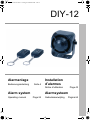
DIY-12
Alarmanlage
Bedienungsanleitung
Seite 4
Installation
d’alarmes
Notice d'utilisation
Alarm system
Operating manual
Page 43
Alarmsysteem
Page 24
Gebruiksaanwijzing
Pagina 64
DIY-12.book Seite 2 Freitag, 24. Februar 2006 3:51 15
DIY-12
1
2
3
1
2
4
1
2
2
3
DIY-12.book Seite 3 Freitag, 24. Februar 2006 3:51 15
DIY-12
5
1
+12V
30
+12V
15
2
3
1A
rt
ge
DIY-12
gn
7
sw
rt
sw
9
8
6
gr
5
31
4
3
DIY-12.book Seite 4 Freitag, 24. Februar 2006 3:51 15
DIY-12
Bitte lesen Sie diese Anleitung vor Einbau und Inbetriebnahme sorgfältig durch und bewahren Sie sie auf. Geben Sie sie im Falle einer Weitergabe des Gerätes an den Nutzer weiter.
Inhaltsverzeichnis
1
Hinweise zur Benutzung der Anleitung . . . . . . . . . . . . . . . . . . . . . . 5
2
Sicherheits- und Einbauhinweise . . . . . . . . . . . . . . . . . . . . . . . . . . 5
3
Lieferumfang . . . . . . . . . . . . . . . . . . . . . . . . . . . . . . . . . . . . . . . . . . 7
4
Bestimmungsgemäßer Gebrauch . . . . . . . . . . . . . . . . . . . . . . . . . . 8
5
Technische Beschreibung . . . . . . . . . . . . . . . . . . . . . . . . . . . . . . . . 8
6
Alarmanlage montieren . . . . . . . . . . . . . . . . . . . . . . . . . . . . . . . . . 10
7
Elektrische Anschlüsse . . . . . . . . . . . . . . . . . . . . . . . . . . . . . . . . . 12
8
Funktion testen . . . . . . . . . . . . . . . . . . . . . . . . . . . . . . . . . . . . . . . 14
9
Alarmanlage bedienen . . . . . . . . . . . . . . . . . . . . . . . . . . . . . . . . . 15
10
Alarmanlage programmieren . . . . . . . . . . . . . . . . . . . . . . . . . . . . 18
11
Reinigung und Pflege . . . . . . . . . . . . . . . . . . . . . . . . . . . . . . . . . . 21
12
Fehler suchen . . . . . . . . . . . . . . . . . . . . . . . . . . . . . . . . . . . . . . . . 21
13
Gewährleistung . . . . . . . . . . . . . . . . . . . . . . . . . . . . . . . . . . . . . . . 22
14
Entsorgung . . . . . . . . . . . . . . . . . . . . . . . . . . . . . . . . . . . . . . . . . . 22
15
Technische Daten . . . . . . . . . . . . . . . . . . . . . . . . . . . . . . . . . . . . . 23
4
DIY-12.book Seite 5 Freitag, 24. Februar 2006 3:51 15
DIY-12
1
Hinweise zur Benutzung der Anleitung
Hinweise zur Benutzung der Anleitung
Achtung!
Sicherheitshinweis: Nichtbeachtung kann zu Materialschäden führen und die Funktion des Gerätes beeinträchtigen.
Achtung!
Sicherheitshinweis, der auf Gefahren mit elektrischem Strom oder
elektrischer Spannung hinweist: Nichtbeachtung kann zu Personen- oder Materialschäden führen und die Funktion des Gerätes
beeinträchtigen.
Hinweis
Ergänzende Informationen zur Bedienung des Gerätes.
➤ Handlung: Dieses Symbol zeigt Ihnen, dass Sie etwas tun müssen. Die
erforderlichen Handlungen werden Schritt für Schritt beschrieben.
✓ Dieses Symbol beschreibt das Ergebnis einer Handlung.
Abb. 1 5, Seite 2: Diese Angabe weist Sie auf ein Element in einer Abbildung hin, in diesem Beispiel auf „Position 5 in Abbildung 1 auf Seite 3“.
Beachten Sie bitte auch die nachfolgenden Sicherheitshinweise.
2
Sicherheits- und Einbauhinweise
Beachten Sie die vom Fahrzeughersteller und vom Kfz-Handwerk vorgeschriebenen Sicherheitshinweise und Auflagen!
Achtung!
WAECO International übernimmt keine Haftung für Schäden aufgrund folgender Punkte:
– Montagefehler,
– Beschädigungen am Gerät durch mechanische Einflüsse und
Überspannungen,
– Veränderungen am Gerät ohne ausdrücklicher Genehmigung
von WAECO International,
– Verwendung für andere als die in der Anleitung beschriebenen
Zwecke.
5
DIY-12.book Seite 6 Freitag, 24. Februar 2006 3:51 15
Sicherheits- und Einbauhinweise
DIY-12
Warnung!
Klemmen Sie wegen der Kurzschlussgefahr vor Arbeiten an der
Fahrzeugelektrik immer den Minuspol ab.
Bei Fahrzeugen mit Zusatzbatterie müssen Sie an dieser ebenfalls
den Minuspol abklemmen.
Warnung!
Unzureichende Leitungsverbindungen können zur Folge haben,
dass durch Kurzschluss
– Kabelbrände entstehen,
– der Airbag ausgelöst wird,
– elektronische Steuerungseinrichtungen beschädigt werden,
– elektrische Funktionen ausfallen (Blinker, Bremslicht, Hupe,
Zündung, Licht).
Beachten Sie deshalb folgende Hinweise:
z Verwenden Sie bei Arbeiten an den folgenden Leitungen nur isolierte
Kabelschuhe, Stecker und Flachsteckhülsen.
– 30 (Eingang von Batterie Plus direkt),
– 15 (Geschaltetes Plus, hinter Batterie),
– 31 (Rückleitung ab Batterie, Masse),
Verwenden Sie keine Lüsterklemmen.
z Verwenden Sie eine Krimpzange zum Verbinden der Kabel.
z Schrauben Sie das Kabel bei Anschlüssen an Leitung 31 (Masse)
– mit Kabelschuh und Zahnscheibe an eine fahrzeugeigene Masseschraube oder
– mit Kabelschuh und Blechschraube an das Karosserieblech.
Achten Sie auf eine gute Masseübertragung!
Beim Abklemmen des Minuspols der Batterie verlieren alle flüchtigen
Speicher der Komfortelektronik ihre gespeicherten Daten.
z Folgende Daten müssen Sie je nach Fahrzeugausstattung neu einstellen:
– Radiocode
– Fahrzeuguhr
– Zeitschaltuhr
– Bordcomputer
– Sitzposition
Hinweise zur Einstellung finden Sie in der jeweiligen Bedienungsanleitung.
6
DIY-12.book Seite 7 Freitag, 24. Februar 2006 3:51 15
DIY-12
Lieferumfang
Beachten Sie folgende Hinweise bei der Montage:
z Befestigen Sie die im Fahrzeug montierten Teile so, dass sie sich unter
keinen Umständen (scharfes Abbremsen, Verkehrsunfall) lösen und zu
Verletzungen der Fahrzeuginsassen führen können.
z Achten Sie beim Bohren auf ausreichenden Freiraum für den Bohreraustritt, um Schäden zu vermeiden (Abb. 1, Seite 2).
z Entgraten Sie jede Bohrung und behandeln Sie diese mit Rostschutzmittel.
Beachten Sie folgende Hinweise bei der Arbeit an elektrischen Teilen:
z Benutzen Sie zum Prüfen der Spannung in elektrischen Leitungen nur
eine Diodenprüflampe oder ein Voltmeter.
Prüflampen mit einem Leuchtkörper nehmen zu hohe Ströme auf, wodurch die Fahrzeugelektronik beschädigt werden kann.
z Beachten Sie beim Verlegen der elektrischen Anschlüsse, dass diese
– nicht geknickt oder verdreht werden,
– nicht an Kanten scheuern,
– nicht ohne Schutz durch scharfkantige Durchführungen verlegt
werden (Abb. 2, Seite 2).
z Isolieren Sie alle Verbindungen und Anschlüsse.
z Sichern Sie die Kabel gegen mechanische Beanspruchung durch Kabelbinder oder Isolierband, z. B. an vorhandenen Leitungen.
3
Lieferumfang
Nr. in
Abb. 3,
Seite 2
Menge
1
1
Kompaktalarmeinheit
2
2
Fernbedienung
1
Status-LED mit Kabel und Sockel
1
Montagematerial
Bezeichnung
Artikel-Nr.
DIY-12-TX
7
DIY-12.book Seite 8 Freitag, 24. Februar 2006 3:51 15
Bestimmungsgemäßer Gebrauch
3.1
DIY-12
Zubehör
Bezeichnung
Artikel-Nr.
Türkontaktschalter-Kit
MSK-150SW
Motorhauben-Kontaktschalter
MS-650KIT
4
Bestimmungsgemäßer Gebrauch
DIY-12 ist eine Alarmanlage für PKWs. Sie dient zum zusätzlichen Schutz
gegen Diebstahl des Fahrzeugs und seines Inhalts.
5
Technische Beschreibung
5.1
Funktionsbeschreibung
Die Alarmanlage DIY-12 besteht aus einer Kompaktalarmeinheit mit Schocksensor, Spannungssensor und Alarmsirene sowie aus einer Status-LED und
zwei Fernbedienungen.
Die Alarmanlage schützt Fahrzeuge und deren Inhalt vor Diebstahl. Bei aktivierter Alarmanlage wird ein Alarm ausgelöst, sobald die Zündung eingeschaltet oder Stöße und Schläge gegen das Fahrzeug vom Schocksensor
gemeldet werden. Mit dem Motorhauben-Kontaktschalter (Zubehör) und
dem Türkontaktschalter-Kit (Zubehör) nachgerüstet, überwacht die Alarmanlage auch das Öffnen der Türen und der Motorhaube.
Die Alarmanlage ist ausgelegt für Fahrzeuge mit einer Bordspannung von
12 V.
DIY-12 wird über eine Zwei-Tasten-Funkfernbedienung bedient. Falls die
Batterien leer sind oder die Fernbedienung verloren gegangen ist oder
beschädigt wurde, können Sie die Alarmanlage ohne Fernbedienung
deaktivieren.
Neue oder zusätzliche Fernbedienungen können Sie an die Alarmanlage anpassen (Anlernen).
Die Quittiertöne der Alarmanlage beim Aktivieren und Deaktivieren können
permanent ausgeschaltet werden. Dafür muss die Alarmanlage bereits beim
Anschließen entsprechend verdrahtet werden.
8
DIY-12.book Seite 9 Freitag, 24. Februar 2006 3:51 15
DIY-12
5.2
Technische Beschreibung
Bedienelemente und Anzeigen der Fernbedienung
Nr. in
Abb. 4,
Seite 2
Bezeichnung
1
Taste ON/OFF: Alarmanlage aktivieren/deaktivieren
2
Taste P: Panikmodus/Suchfunktion, Einstellungen vornehmen
3
LED: leuchtet, wenn eine der beiden Tasten oder beide
Tasten gleichzeitig gedrückt werden
5.3
Mögliche Betriebszustände
Die Alarmanlage kennt folgende vier Betriebszustände:
z betriebsbereit
Die Alarmanlage ist ständig betriebsbereit, sobald sie eingebaut und
korrekt angeschlossen ist. Sie löst in diesem Betriebszustand jedoch
keinen Alarm aus.
z aktiviert
Wenn die Alarmanlage aktiviert ist, kann sie einen Alarm auslösen. Dies
ist der Fall, wenn z. B. das Fahrzeug gestartet wird oder wenn jemand am
Fahrzeug rüttelt. Wenn Sie wieder losfahren möchten, müssen Sie die
Alarmanlage deaktivieren. Dann ist sie wieder im Betriebszustand „betriebsbereit“.
z Voralarm ausgelöst
Wenn der Schocksensor nur eine leichte Erschütterung erkennt, löst die
Alarmanlage Voralarm aus.:Die Alarmsirene gibt 5 Signaltöne ab.
Anschließend kehrt die Alarmanlage selbstständig zum Betriebszustand
„aktiviert“ zurück.
z Alarm ausgelöst
Die Alarmsirene ertönt für 30 Sekunden, und die Status-LED blinkt
schnell.
Bei ausgelöstem Alarm können Sie den Alarm abschalten und dann die
Alarmanlage entweder aktiv lassen (Betriebszustand „aktiviert“) oder
deaktivieren (Betriebszustand „betriebsbereit“).
Nach dem Abschalten des Alarms durch den Handsender bleibt die
Alarmanlage im aktivierten Zustand
9
DIY-12.book Seite 10 Freitag, 24. Februar 2006 3:51 15
Alarmanlage montieren
6
DIY-12
Alarmanlage montieren
Hinweis
Wenn Sie nicht über ausreichende technische Kenntnisse für das
Einbauen und Anschließen von Komponenten in Fahrzeugen verfügen, sollten Sie sich die Alarmanlage von einem Fachmann ins
Fahrzeug einbauen lassen.
6.1
Kompaktalarmeinheit montieren
➤ Wählen Sie einen geeigneten Montageort.
Hinweis
Beachten Sie bei der Wahl des Montageortes folgende Hinweise:
➤ Montieren Sie die Kompaktalarmeinheit
– im Motorraum in der Nähe der Fahrzeugbatterie,
– mit dem Hauptanschlusskabel nach unten,
– nicht im Einflussbereich starker elektrischer Felder, z. B. Zündanlage
oder Motorsteuergerät,
– nicht direkt im Bereich der Auspuffanlage oder im Spritzwasserbereich.
➤ Schrauben Sie die Kompaktalarmeinheit mit den beiliegenden Schrauben
fest.
Hinweis
Die Kompaktalarmeinheit sollte fest mit der Fahrzeugkarosserie
verschraubt werden, um eine optimale Funktion des Schocksensors zu gewährleisten.
10
DIY-12.book Seite 11 Freitag, 24. Februar 2006 3:51 15
DIY-12
6.2
Alarmanlage montieren
Status-LED montieren
Achtung!
Bevor Sie irgendwelche Bohrungen vornehmen, stellen Sie sicher,
dass keine elektrischen Kabel oder andere Teile des Fahrzeuges
durch Bohren, Sägen und Feilen beschädigt werden.
➤ Bohren Sie ein Loch mit einem Durchmesser von 8 mm in das Armaturenbrett oder in eine vorhandene Kunststoffabdeckung.
➤ Führen Sie das Kabel mit der Status-LED durch die Bohrung und stecken
Sie die Status-LED in die Bohrung, bis sie einrastet.
➤ Die Status-LED ist durch kleine Widerhaken gegen einfaches Herausrutschen gesichert.
➤ Verlegen Sie das Kabel zur Kompaktalarmeinheit und stecken Sie den
Stecker in den zweipoligen Anschluss.
6.3
Motorhauben-Kontaktschalter (Zubehör) montieren
Dieser Schalter ist als Zubehör erhältlich.
Achtung!
Bevor Sie irgendwelche Bohrungen vornehmen, stellen Sie sicher,
dass keine elektrischen Kabel oder andere Teile des Fahrzeuges
durch Bohren, Sägen und Feilen beschädigt werden.
➤ Suchen Sie im Motorraum eine geeignete Stelle aus und bohren Sie ein
Loch mit einem Durchmesser von 8 mm.
➤ Achten Sie bei der Montage darauf, dass der Abstand zur geschlossenen
Haube minimal 22 mm und maximal 27 mm beträgt.
Ermitteln Sie diese Abstände mit Knetmasse.
Sie können den minimalen Abstand z. B. durch Kürzen des Schalters
noch verringern.
➤ Prüfen Sie nach dem Einbau die Schaltfunktion.
11
DIY-12.book Seite 12 Freitag, 24. Februar 2006 3:51 15
Elektrische Anschlüsse
7
Elektrische Anschlüsse
7.1
Kabel verlegen
DIY-12
Achtung!
Bevor Sie irgendwelche Bohrungen vornehmen, stellen Sie sicher,
dass keine elektrischen Kabel oder andere Teile des Fahrzeuges
durch Bohren, Sägen und Feilen beschädigt werden.
Hinweis
Verwenden Sie für die Durchführung der Anschlusskabel nach
Möglichkeit Originaldurchführungen oder andere Durchführungsmöglichkeiten, z. B. Verkleidungskanten, Lüftungsgitter oder Blindschalter. Wenn kein Gummistopfen vorhanden ist, fertigen Sie eine
entsprechende Bohrung von ca. Ø 13 mm an, und setzen Sie eine
Kabeldurchführungstülle ein.
Hinweis
Nicht fachgerechte Kabelverlegungen und Kabelverbindungen
führen immer wieder zu Fehlfunktionen oder Beschädigungen von
Bauteilen. Eine korrekte Kabelverlegung bzw. Kabelverbindung ist
die Grundvoraussetzung für eine dauerhafte und fehlerfreie Funktion der nachgerüsteten Komponenten.
Beachten Sie deshalb folgende Hinweise:
z Verlegen Sie die Kabel nach Möglichkeit immer im Fahrzeuginneren,
denn dort sind sie besser geschützt als außen am Fahrzeug.
Wenn Sie die Kabel trotzdem außerhalb des Fahrzeuges verlegen,
achten Sie auf eine sichere Befestigung (durch zusätzliche Kabelbinder,
Isolierband usw.).
z Um Beschädigungen am Kabel zu vermeiden, halten Sie beim Verlegen
der Kabel immer ausreichend Abstand zu heißen und sich bewegenden
Fahrzeugteilen (Auspuffrohre, Antriebswellen, Lichtmaschine, Lüfter,
Heizung usw.).
z Umwickeln Sie die Steckverbindungen der Verbindungskabel zum Schutz
gegen das Eindringen von Wasser und jede Verbindung an einem Kabel
(auch im Fahrzeug) dicht mit einem guten Isolierband. Am besten eignet
sich selbstvulkanisierendes Dichtband, z. B. von 3M.
12
DIY-12.book Seite 13 Freitag, 24. Februar 2006 3:51 15
DIY-12
Elektrische Anschlüsse
z Beachten Sie beim Verlegen der Kabel, dass diese
– nicht stark geknickt oder verdreht werden,
– nicht an Kanten scheuern,
– nicht ohne Schutz durch scharfkantige Durchführungen verlegt
werden.
z Befestigen Sie die Kabel sicher im Fahrzeug mit Kabelbindern, Isolierband oder durch Ankleben mit Klebstoff, um ein Verfangen (Sturzgefahr)
zu vermeiden.
z Schützen Sie jeden Durchbruch an der Außenhaut der Karosserie durch
geeignete Maßnahmen gegen Wassereinbruch, z. B. durch Einsetzen
des Kabels mit Dichtungsmasse und durch Abspritzen des Kabels und
der Durchführungstülle mit Dichtungsmasse.
7.2
Alarmanlage anschließen
Einen Überblick über die gesamte Verschaltung finden Sie im Schaltplan in
Abb. 5, Seite 3.
Nr.
Erläuterung
1
Klemme 30, +12 V
2
Klemme 15, geschaltete +12 V
3
Kompaktalarmeinheit
4
Kabel für das Ausschalten der Quittiertöne
5
Status-LED
6
Kabel zum Motorhauben-Kontaktschalter
7
Türkontaktschalter-Kit
8
Original-Kabel zum Kofferraum-Kontaktschalter
9
Original-Kabel zum Türkontaktschalter
rt
rot
ge
gelb
gn
grün
sw
schwarz
gr
grau
13
DIY-12.book Seite 14 Freitag, 24. Februar 2006 3:51 15
Funktion testen
DIY-12
➤ Schließen Sie das schwarze Kabel an Masse an (Klemme -31).
➤ Schließen Sie das rote Kabel an ein permanent +12 Volt führendes
Kabel (Klemme +30) an.
➤ Verbinden Sie das gelbe Kabel mit einem geschalteten Plus
(Klemme 15).
➤ Optional: Schließen Sie das grüne Kabel an den Motorhauben-Kontaktschalter (Zubehör) an.
➤ Optional: Schließen Sie das Türkontaktschalter-Kit (Zubehör) entsprechend des Schaltplanes an das grüne Kabel an.
➤ Wenn Sie die Quittiertöne der Alarmanlage beim Aktivieren und
Deaktivieren ausschalten möchten: Verbinden Sie das graue Kabel mit
dem schwarzen Kabel oder schließen Sie es an Masse an.
8
Funktion testen
8.1
Schocksensor testen
Der Schocksensor ist ab Werk voreingestellt. Die Empfindlichkeit ist richtig
eingestellt, wenn die Alarmanlage bei einem heftigen Stoß gegen das Fahrzeug Alarm auslöst.
Gehen Sie beim Funktionstest wie folgt vor:
➤ Aktivieren Sie die Alarmanlage (siehe Kapitel „Alarmanlage aktivieren“
auf Seite 15).
➤ Rütteln Sie am Fahrzeug.
Wenn bei Schlägen auf die Scheiben ein Alarm ausgelöst wird, müssen Sie
die Empfindlichkeit verringern (siehe Kapitel „Empfindlichkeit des Schocksensors einstellen“ auf Seite 19).
Wenn der Schocksensor zu empfindlich eingestellt ist, kann durch vorbeifahrende Fahrzeuge ein Alarm ausgelöst werden. Stellen Sie deshalb die
Empfindlichkeit sorgfältig und nicht zu hoch ein.
8.2
Übrige Alarmeingänge testen
➤ Prüfen Sie der Reihe nach die Funktion der übrigen Alarmeingänge,
indem Sie jeweils einen Alarm auslösen.
14
DIY-12.book Seite 15 Freitag, 24. Februar 2006 3:51 15
DIY-12
8.3
Alarmanlage bedienen
Akustische und optische Signale testen
Während des Alarms müssen die Alarmsirene sowie die Status-LED den
Alarm signalisieren.
8.4
Fernbedienung testen
➤ Testen Sie alle Schaltfunktionen mit beiden Fernbedienungen.
Wenn die Anlage auf eine Fernbedienung nicht reagiert, lernen Sie die Fernbedienungen neu an (siehe Kapitel „Fernbedienungen anlernen“ auf
Seite 18).
Hinweis
Die Reichweite der Fernbedienung kann durch massive Metallteile
und starke elektrische Felder eingeschränkt werden; sie liegt in der
Regel bei 10 m bis 20 m.
9
Alarmanlage bedienen
9.1
Alarmanlage aktivieren
➤ Schalten Sie die Zündung aus.
➤ Steigen Sie aus dem Fahrzeug aus.
➤ Stellen Sie sicher, dass alle Türen und Klappen geschlossen sind.
➤ Drücken Sie die Taste ON/OFF der Fernbedienung.
✓ Die Alarmanlage gibt einen Quittierton ab, falls diese Funktion nicht abgeschaltet ist.
✓ Die Status-LED beginnt zu blinken. Zunächst wird nur die Zündung überwacht. Nach 5 Sekunden ist die Alarmanlage vollständig aktiviert: Der
Schocksensor und der Spannungssensor werden ebenfalls überwacht.
15
DIY-12.book Seite 16 Freitag, 24. Februar 2006 3:51 15
Alarmanlage bedienen
DIY-12
Hinweis
Nur bei angeschlossenen Türkontakt- oder Motorhauben-Kontaktschaltern (Zubehör):
Wird die Alarmanlage bei geöffneter Tür oder Motorhaube aktiviert,
ertönen zwei Quittiertöne (falls diese Funktion nicht abgeschaltet
ist), um die Störung anzuzeigen. Die Alarmanlage ist zwar aktiviert,
schließt aber bei der Überwachung den betroffenen Sensorbereich
aus, bis die Störquelle aufgehoben ist z. B. die Fahrzeugtür ordnungsgemäß geschlossen.
Alarmanlage so aktivieren, dass das Fahrzeug besetzt bleiben kann
Sie können die Alarmanlage so einstellen, dass der Schocksensor keinen
Alarm auslöst, z. B. um ein Haustier im Fahrzeug zu lassen.
➤ Drücken Sie die Taste ON/OFF der Fernbedienung.
✓ Die Alarmsirene gibt einen Quittierton ab, falls diese Funktion nicht abgeschaltet ist.
➤ Drücken Sie die Taste P der Fernbedienung innerhalb von 5 Sekunden.
✓ Die Alarmsirene gibt einen Quittierton ab, falls diese Funktion nicht abgeschaltet ist. Die Zündung wird überwacht. Nach 5 Sekunden ist die Alarmanlage bis auf den Schocksensor vollständig aktiviert.
9.2
Alarmanlage deaktivieren
➤ Drücken Sie die Taste ON/OFF der Fernbedienung.
✓ Die Alarmanlage wird deaktiviert.
✓ Die Alarmsirene gibt zwei Quittiertöne ab, falls diese Funktion nicht abgeschaltet ist.
Hinweis
Wenn die Alarmsirene vier Quittiertöne abgibt und die Status-LED
nicht blinkt, wurde der Alarm ausgelöst, während die Alarmanlage
aktiviert war.
16
DIY-12.book Seite 17 Freitag, 24. Februar 2006 3:51 15
DIY-12
Alarmanlage bedienen
Alarmanlage ohne Fernbedienung deaktivieren
Falls Sie die Fernbedienung verlegt haben, die Batterien leer sind oder die
Fernbedienung beschädigt ist, können Sie die Alarmanlange wie folgt
deaktivieren:
➤ Schalten Sie die Zündung 5 Mal an und aus.
➤ Schalten Sie die Zündung innerhalb von 8 Sekunden wieder ein.
✓ Die Alarmsirene gibt vier Quittiertöne ab, falls diese Funktion nicht
deaktiviert ist.
✓ Die Alarmanlage wird deaktiviert.
9.3
Alarm abschalten
Wenn ein Alarm ausgelöst wurde, können Sie ihn wie folgt abschalten:
➤ Drücken Sie die Taste ON/OFF der Fernbedienung.
✓ Der Alarm wird abgeschaltet, die Alarmanlage bleibt aktiviert.
9.4
Panik-Modus/Fahrzeug-Suchfunktion verwenden
Die Alarmanlage besitzt einen Panik-Modus. Sie können per Fernbedienung
einen Alarm auslösen, wenn Sie z. B. angegriffen werden, um Angreifer abzuschrecken. Diese Funktion können Sie auch nutzen, um sich den Standort
ihres Fahrzeugs akustisch anzeigen zu lassen.
➤ Drücken Sie die Taste P der Fernbedienung und halten Sie sie für 3 Sekunden gedrückt.
✓ Die Alarmsirene wird für 30 Sekunden eingeschaltet.
✓ Das Fahrzeug bleibt funktionstüchtig, so dass Sie wegfahren können.
Panik-Modus/Suchfunktion ausschalten
➤ Drücken Sie die Taste ON/OFF der Fernbedienung.
✓ Der Panik-Modus wird ausgeschaltet.
17
DIY-12.book Seite 18 Freitag, 24. Februar 2006 3:51 15
Alarmanlage programmieren
9.5
DIY-12
Funktionstabelle
In der folgenden Tabelle finden Sie eine Auflistung aller Funktionen und wie
Sie diese aktivieren.
Taste
ON/OFF
Funktion
Bedingung
Aktivieren
Zündung aus
z
Aktivieren mit Abschalten des
Schocksensors
Zündung aus
1.z
Deaktivieren
Zündung aus
z
Taste P
2. z
Panik-Modus
z 3s
Fahrzeug-Suchfunktion
z 3s
z
entsprechende Taste drücken
z 3 s entsprechende Taste drücken und 3 Sekunden gedrückt halten
10
Alarmanlage programmieren
10.1
Fernbedienungen anlernen
Die Alarmanlage DIY-12 kann mit bis zu vier Fernbedienungen bedient
werden.
Wenn Sie eine Fernbedienung neu anlernen, müssen Sie auch alle bereits
angemeldeten Fernbedienungen neu anlernen.
➤ Deaktivieren Sie die Alarmanlage (siehe Kapitel „Alarmanlage deaktivieren“ auf Seite 16).
➤ Schalten Sie die Zündung 7 Mal an und aus.
➤ Schalten Sie die Zündung innerhalb von 8 Sekunden ein.
✓ Die Alarmsirene gibt nach 8 Sekunden drei Signaltöne ab.
✓ Die Alarmanlage befindet sich in Lernbereitschaft.
➤ Drücken Sie innerhalb von 8 Sekunden irgendeine Taste der anzulernenden Fernbedienung.
✓ Die Alarmsirene gibt für die erste Fernbedienung einen Signalton ab.
18
DIY-12.book Seite 19 Freitag, 24. Februar 2006 3:51 15
DIY-12
Alarmanlage programmieren
Hinweis
Lernen Sie alle Fernbedienungen, die Sie nutzen wollen, zur gleichen Zeit an. Die Alarmsirene bestätigt
– bei der zweiten Fernbedienung mit 2 Signaltönen,
– bei der dritten Fernbedienung mit 3 Signaltönen und
– bei der vierten Fernbedienung mit 4 Signaltönen.
Wenn Sie nicht innerhalb von 8 Sekunden eine Taste einer Fernbedienung
drücken oder wenn Sie die Zündung ausschalten, ist der Lernmodus
beendet.
✓ Das Anlernen ist abgeschlossen.
10.2
Empfindlichkeit des Schocksensors einstellen
Der Schocksensor ist ab Werk voreingestellt. Die Empfindlichkeit ist richtig
eingestellt, wenn die Alarmanlage bei einem heftigen Stoß gegen das Fahrzeug Alarm auslöst.
➤ Deaktivieren Sie die Alarmanlage.
➤ Drücken Sie innerhalb von 8 Sekunden nach dem Deaktivieren gleichzeitig Taste ON/OFF und Taste P der Fernbedienung.
✓ Die Alarmsirene gibt einen Signalton ab.
✓ Die Alarmanlage befindet sich im Modus zur Einstellung des Schocksensors.
➤ Drücken Sie Taste P.
✓ Die Alarmanlage zeigt durch die Anzahl der Signaltöne, welche Empfindlichkeitsstufe des Schocksensors eingestellt ist. Der Schocksensor hat
8 verschiedene Empfindlichkeitsstufen.
➤ Drücken Sie Taste P, um in die nächsthöhere Empfindlichkeitsstufe zu
wechseln.
➤ Testen Sie jeweils durch Schläge auf die Scheiben, ob die Empfindlichkeitsstufe nicht zu hoch ist: Wenn die Alarmanlage einen Alarm auslösen
würde, ertönt ein Signalton. Wählen Sie dann eine geringere Empfindlichkeitsstufe.
➤ Drücken Sie Taste ON/OFF.
✓ Sie verlassen den Einstellmodus. Die Empfindlichkeitsstufe ist gespeichert.
19
DIY-12.book Seite 20 Freitag, 24. Februar 2006 3:51 15
Alarmanlage programmieren
10.3
DIY-12
Spannungsüberwachung einstellen
➤ Deaktivieren Sie die Alarmanlage.
➤ Schalten Sie die Zündung 4 Mal ein und aus.
➤ Schalten Sie die Zündung innerhalb von 8 Sekunden erneut ein.
✓ Nach 8 Sekunden gibt die Alarmsirene 2 Signaltöne ab.
✓ Sie befindet sich im Einstell-Modus für die Spannungsüberwachung.
Zeitverzögerung einstellen
Sie können zwischen zwei Stufen auswählen:
– 8 Sekunden oder
– 4 Minuten
➤ Drücken Sie im Einstell-Modus für die Spannungsüberwachung die
Taste ON/OFF.
✓ Die Alarmanlage zeigt Ihnen die Einstellung an:
– 1 Signalton: 8 Sekunden Zeitverzögerung sind aktiviert (Werkseinstellung)
– 2 Signaltöne: 4 Minuten Zeitverzögerung sind aktiviert.
➤ Wenn Sie die Zeitverzögerung ändern möchten: Drücken Sie erneut
Taste ON/OFF.
✓ Es ertönt ein Signalton.
Spannungsüberwachung aktivieren und deaktivieren
➤ Drücken Sie im Einstell-Modus für die Spannungsüberwachung die
Taste P.
✓ Die Alarmanlage zeigt Ihnen die Einstellung an:
– 1 Signalton: Spannnungsüberwachung ist aktiviert
– 2 Signaltöne: Spannungsüberwachung ist deaktiviert (Werkseinstellung).
➤ Wenn Sie die Zeitverzögerung ändern möchten: Drücken Sie erneut
Taste P.
✓ Es ertönt ein Signalton, falls diese Funktion nicht abgestellt ist.
20
DIY-12.book Seite 21 Freitag, 24. Februar 2006 3:51 15
DIY-12
10.4
Reinigung und Pflege
Sirenenklang auswählen
Sie können zwischen für das Alarmsignal zwischen 8 verschiedenen
Sirenenklängen auswählen.
➤ Deaktivieren Sie die Alarmanlage.
➤ Schalten Sie die Zündung 5 Mal ein und aus.
➤ Schalten Sie die Zündung innerhalb von 8 Sekunden erneut ein.
✓ Nach 8 Sekunden gibt die Alarmsirene einen Signalton ab.
✓ Sie befinden sich im Einstell-Modus für den Sirenenklang.
➤ Drücken Sie Taste P, um einen anderen Sirenenklang auszuwählen.
✓ Die Alarmsirene ertönt in dem neuen Sirenenklang.
➤ Wenn Sie den Sirenenklang ändern möchten: Drücken Sie erneut die
Taste P.
➤ Drücken Sie Taste ON/OFF, um den aktuellen Sirenenklang zu
speichern.
✓ Der Sirenenklang ist gespeichert.
11
Reinigung und Pflege
Achtung!
Keine scharfen oder harten Mittel zur Reinigung verwenden, da
dies zu einer Beschädigung der Komponenten führen kann.
12
Fehler suchen
Die Reichweite der Fernbedienung verringert sich.
Die Batterien sind erschöpft.
Sie haben die Fernbedienung verloren, oder die Fernbedienung ist
beschädigt.
➤ Schalten Sie die Alarmanlage mit Hilfe der Zündung aus (siehe Kapitel
„Alarmanlage deaktivieren“ auf Seite 16).
21
DIY-12.book Seite 22 Freitag, 24. Februar 2006 3:51 15
Gewährleistung
DIY-12
Sie erhalten drei Signaltöne/Blinkzeichen anstelle der gewohnten
Meldung, wenn Sie die Alarmanlage einschalten.
Die Alarmanlage warnt Sie, dass die Motorraumhaube offen ist (nur bei
angeschlossenem, optionalen Motorhauben-Kontaktschalter).
➤ Schalten Sie die Alarmanlage aus.
➤ Beseitigen Sie die Ursache der Fehlermeldung.
➤ Schalten Sie die Alarmanlage wieder ein.
Sie erhalten vier Signaltöne/Blinkzeichen anstelle der gewohnten zwei
Meldungen, wenn Sie die Alarmanlage ausschalten.
Die Alarmanlage hatte einen Alarm ausgelöst.
13
Gewährleistung
Es gilt die gesetzliche Gewährleistungsfrist. Sollte das Produkt defekt sein,
schicken Sie es bitte an die WAECO-Niederlassung in Ihrem Land (siehe
Adressen Rückseite der Anleitung) oder an Ihren Fachhändler. Zur Reparatur- bzw. Gewährleistungsbearbeitung müssen Sie folgende Unterlagen mitschicken:
z eine Kopie der Rechnung mit Kaufdatum,
z einen Reklamationsgrund oder eine Fehlerbeschreibung.
14
Entsorgung
➤ Geben Sie das Verpackungsmaterial möglichst in den entsprechenden
Recycling-Müll.
Wenn Sie das Gerät endgültig außer Betrieb nehmen, informieren
Sie sich bitte beim nächsten Recyclingcenter oder bei Ihrem Fachhändler über die zutreffenden Entsorgungsvorschriften.
22
DIY-12.book Seite 23 Freitag, 24. Februar 2006 3:51 15
DIY-12
15
Technische Daten
Technische Daten
Kompaktalarmeinheit
Betriebsspannung:
12 Volt DC
Sendebereich
bis 20 m
Stromaufnahme:
ca. 20 mA (aktiviert)
ca. 8 mA (deaktiviert)
Betriebstemperatur:
–40 °C bis +85 °C
Fernbedienung
Sendefrequenz:
433,92 MHz
Kodierung:
fest eingestellter Code
Betriebsspannung:
9 bis 16 Volt DC
Batterietyp:
GP Super GP Alkaline 23A, 12 V
Betriebstemperatur:
–20 °C bis +75 °C
Ausführungen, dem technischen Fortschritt dienende Änderungen und
Liefermöglichkeiten vorbehalten.
Zulassungen
Das Gerät hat die e13-Zulassung.
3
23
DIY-12.book Seite 24 Freitag, 24. Februar 2006 3:51 15
DIY-12
Please read this manual carefully before installing and starting up and
store it in a safe place. If the device is handed over to another person,
this operating manual must be handed over along with the device.
Contents
1
Notes on using the manual . . . . . . . . . . . . . . . . . . . . . . . . . . . . . . 25
2
Safety and installation instructions . . . . . . . . . . . . . . . . . . . . . . . . 25
3
Scope of delivery . . . . . . . . . . . . . . . . . . . . . . . . . . . . . . . . . . . . . 27
4
Proper use . . . . . . . . . . . . . . . . . . . . . . . . . . . . . . . . . . . . . . . . . . 28
5
Technical description . . . . . . . . . . . . . . . . . . . . . . . . . . . . . . . . . . 28
6
Installing the alarm system . . . . . . . . . . . . . . . . . . . . . . . . . . . . . . 30
7
Electrical connections . . . . . . . . . . . . . . . . . . . . . . . . . . . . . . . . . . 31
8
Performing a functional test . . . . . . . . . . . . . . . . . . . . . . . . . . . . . 34
9
Operating the alarm system . . . . . . . . . . . . . . . . . . . . . . . . . . . . . 35
10
Programming the alarm system . . . . . . . . . . . . . . . . . . . . . . . . . . 37
11
Cleaning and maintenance . . . . . . . . . . . . . . . . . . . . . . . . . . . . . . 40
12
Troubleshooting . . . . . . . . . . . . . . . . . . . . . . . . . . . . . . . . . . . . . . 40
13
Guarantee . . . . . . . . . . . . . . . . . . . . . . . . . . . . . . . . . . . . . . . . . . . 41
14
Disposal . . . . . . . . . . . . . . . . . . . . . . . . . . . . . . . . . . . . . . . . . . . . 41
15
Technical data . . . . . . . . . . . . . . . . . . . . . . . . . . . . . . . . . . . . . . . . 42
24
DIY-12.book Seite 25 Freitag, 24. Februar 2006 3:51 15
DIY-12
1
Notes on using the manual
Notes on using the manual
Caution
Safety instruction: Failure to observe this instruction can cause
material damage and impair the function of the device.
Caution
Safety instruction relating to a danger from an electrical current or
voltage. Failure to observe this instruction can cause material damage or personal injury and impair the function of the device.
Note
Supplementary information for operating the device.
➤ Action: This symbol indicates that action is required on your part.
The required action is described step-by-step.
✓ This symbol describes the result of an action.
Fig. 1 5, page 2: This refers to an element in an illustration: In this case,
“item 5 in figure 1 on page 3”.
Please observe the following safety instructions.
2
Safety and installation instructions
Please observe the prescribed safety instructions and stipulations
from the vehicle manufacturer and service workshops.
Caution
WAECO International will not be held liable for claims for damage
resulting from the following:
– Installation errors
– Damage to the device resulting from mechanical influences and
overvoltage
– Alterations made to the device without the explicit permission of
WAECO International
– Use for purposes other than those described in the operating
manual
25
DIY-12.book Seite 26 Freitag, 24. Februar 2006 3:51 15
Safety and installation instructions
DIY-12
Warning
To prevent the risk of short circuits, always disconnect the negative
terminal of the vehicle’s electrical system before working on it.
If the vehicle has an additional battery, its negative terminal should
also be disconnected.
Warning
Inadequate cable connections can cause short circuits, resulting in:
– Cable fires
– The airbag being triggered
– Damage to electronic control equipment
– Electrical malfunctions (indicators, brake light, horn, ignition,
lights)
Please observe the following instructions:
z When working on the following supply lines, only use insulated cable lugs,
plugs and tab sleeves.
– 30 (direct supply from positive battery terminal)
– 15 (connected positive terminal, behind the battery)
– 31 (return cable from the battery, earth)
Do not use terminal strips.
z Use a crimping tool to connect the cables.
z For connections to wire 31 (earth):
– Screw on the cable using a cable lug and serrated washer with one of
the vehicle’s earth bolts
– Screw the cable to the bodywork using a cable lug and a self-tapping
screw
Make sure there is a good earth connection.
If you disconnect the negative terminal of the battery, all data stored in the
volatile memories will be lost.
z The following data must be set again, depending on the vehicle
equipment options:
– Radio code
– Vehicle clock
– Timer
– On-board computer
– Seat position
You can find instructions for making these settings in the appropriate
operating instructions.
26
DIY-12.book Seite 27 Freitag, 24. Februar 2006 3:51 15
DIY-12
Scope of delivery
Observe the following installation instructions:
z Secure the parts installed in the vehicle in such a way that they cannot
become loose under any circumstances (sudden braking, accidents)
and cause injuries to the occupants of the vehicle.
z When drilling holes, make sure the drill bit will not damage anything on the
other side (fig. 1, page 2).
z Deburr all drill holes and treat them with a rust-protection agent.
Observe the following instructions when working with electrical parts:
z Only use a diode test lamp or voltmeter to test voltages in electric cables.
Test lamps with an illuminant consume voltages which are too high and
which can damage the vehicle’s electronic system.
z When making electrical connections, ensure that:
– They are not kinked or twisted
– They do not rub on edges
– They are not laid in sharp edged ducts without protection (fig. 2,
page 2)
z Insulate all connections.
z Protect the cables from mechanical wear (for example rubbing against
existing cables) using cable binders or insulating tape.
3
Scope of delivery
No. in
fig. 3,
page 2
Quantity Description
1
1
Compact alarm unit
2
2
Remote control
1
Status LED with cable and socket
1
Installation material
Item number
DIY-12-TX
27
DIY-12.book Seite 28 Freitag, 24. Februar 2006 3:51 15
Proper use
3.1
DIY-12
Accessories
Description
Item number
Door contact switch kit
MSK-150SW
Bonnet contact switch
MS-650KIT
4
Proper use
The DIY-12 is a car alarm system. It offers additional protection against the
theft of your vehicle and its contents.
5
Technical description
5.1
Function description
The DIY-12 alarm system consists of a compact alarm unit with a shock
sensor, voltage sensor and alarm siren, as well as a status LED and two
remote control devices.
The alarm system protects vehicles and their contents from theft. When the
alarm system is armed, an alarm is triggered as soon as the ignition is
switched on, or if the shock sensor detects impacts or blows to the vehicle.
Contact switches are available as accessories for the bonnet and the doors,
so that the alarm system can be upgraded to detect them being opened.
The alarm system is designed for vehicles with an on-board 12 V power
supply.
The DIY-12 is operated with a two-button remote control. If the batteries are
flat or the remote control is lost or damaged, you can turn the alarm system
off without it.
You can program new or additional remote control devices for the alarm
system.
You can permanently deactivate the acknowledgement tones when you arm
or disarm the alarm system. To do this, the alarm system must be wired
correspondingly.
28
DIY-12.book Seite 29 Freitag, 24. Februar 2006 3:51 15
DIY-12
5.2
Technical description
Remote control elements and displays
No. in
fig. 4,
page 2
Description
1
ON/OFF button: arms and disarms the alarm
2
P button: panic mode, search function, configuration
3
LED: flashes when either or both of the buttons are pressed.
5.3
Possible operating states
The alarm system has the following four operating states:
z Stand-by
The alarm system is constantly on stand-by as soon as it is installed and
correctly connected. However, it does not trigger the alarm when in standby.
z Armed
If the system is armed, it can trigger an alarm. This happens, for example,
if someone starts the vehicle or shakes it. If you wish to drive off, you must
first disarm the alarm system. The system is then in stand-by mode.
z Warning triggered
If the shock sensor detects a minor shake, the alarm system emits a warning. The siren sounds five times.
The alarm system then returns to “armed” status.
z Alarm triggered
The alarm sounds for 30 seconds and the status LED flashes quickly.
If the alarm is triggered, you can switch off the alarm and then either
leave the system activated (“armed” status) or deactivate it (“standby”).
When you switch off the alarm with the remote control, the system
remains armed.
29
DIY-12.book Seite 30 Freitag, 24. Februar 2006 3:51 15
Installing the alarm system
6
DIY-12
Installing the alarm system
Note
If you do not have sufficient technical expertise for installing and
connecting the components in vehicles, you should have a specialist install the alarm system for you.
6.1
Installing the compact alarm unit
➤ Select a suitable installation location.
Note
When selecting the installation location, observe the following
instructions:
➤ Install the compact alarm unit:
– In the engine compartment near the battery
– With the main connection cable facing downwards
– Away from strong electrical fields such as the ignition system or central
controller electronics
– Not directly near the exhaust system or where water might splash
➤ Tightly fasten the compact alarm unit using the screws provided.
Note
The compact arm unit should be bolted tightly to the bodywork to
ensure that the shock sensor works properly.
6.2
Installing the status LED
Caution
Before drilling any holes, ensure that no electrical cables or other
parts of the vehicle can be damaged by drilling, sawing and filing.
➤ Drill a hole with a diameter of 8 mm in the dashboard or in an existing
plastic cover.
➤ Guide the status LED cable through the drill hole and insert the status
LED in the drill hole until it latches into place.
➤ The status LED is secured against slipping out with a small hook.
➤ Lay the cable to the compact alarm unit and insert the plug in the two-pin
connection.
30
DIY-12.book Seite 31 Freitag, 24. Februar 2006 3:51 15
DIY-12
6.3
Electrical connections
Installing the bonnet contact switch (optional
accessory)
This switch is available as an accessory.
Caution
Before drilling any holes, ensure that no electrical cables or other
parts of the vehicle can be damaged by drilling, sawing and filing.
➤ Find a suitable location in the engine compartment and drill a hole with a
diameter of 8 mm.
➤ During installation make sure the distance to the closed bonnet is
between 22 mm and 27 mm.
Use putty to check this distance.
You can further reduce the minimum distance by shortening the switch.
➤ Test the switch function after installation.
7
Electrical connections
7.1
Laying cables
Caution
Before drilling any holes, ensure that no electrical cables or other
parts of the vehicle can be damaged by drilling, sawing and filing.
Note
As far as possible, use original ducts for laying the cables, or other
suitable options such as panelling edges, ventilation grilles or
dummy plugs. If there is no rubber plug, make a suitable hole with
a diameter of around 13 mm and insert a cable sleeve.
Note
Cables and connections which are not properly installed will cause
malfunctions or damage to components. Correct installation of
cables and connections ensures lasting and trouble-free operation
of the retrofitted components.
31
DIY-12.book Seite 32 Freitag, 24. Februar 2006 3:51 15
Electrical connections
DIY-12
Please observe the following instructions:
z Wherever possible, lay cables inside the vehicle, as they are better
protected there than outside.
If you do need to lay a cable outside the vehicle, ensure that it is well
fastened (use additional cable ties, insulating tape etc.).
z To prevent damage to the cables, when laying them, ensure that they are
far enough away from hot or moving vehicle components (exhaust pipes,
drive shafts, light systems, fans, heater etc.).
z Wrap insulating tape around the plug connections of the connecting
cables and every connection on a cable (including inside the vehicle) to
protect them from exposure to water. The most suitable tape for this is
self-vulcanising tape, e.g. from 3M.
z When laying the cables, make sure:
– They are not kinked or twisted
– They do not rub on edges
– They are not laid in sharp-edged ducts without protection.
z Attach the cables securely in the vehicle with cable binders, insulating
tape or by glueing them to prevent them from being tripped over.
z Protect every through-hole made in the outer skin of the bodywork against
water penetration, for example by using a cable with a sealant and by
spraying the cable and the cable sleeve with sealant.
32
DIY-12.book Seite 33 Freitag, 24. Februar 2006 3:51 15
DIY-12
7.2
Electrical connections
Connecting the alarm system
You will find a summary of the wiring in the circuit diagram in fig. 5, page 3.
No.
Explanation
1
Terminal 30, +12 V
2
Terminal 15, switched +12 V
3
Compact alarm unit
4
Cable for deactivating acknowledgement tones
5
Status LED
6
Cable to bonnet contact switch
7
Door contact switch kit
8
Original cable to boot contact switch
9
Original cable to door contact switch
rt
Red
ge
Yellow
gn
Green
sw
Black
gr
Grey
➤ Connect the black cable to earth (terminal -31).
➤ Connect the red cable to a cable with a permanent +12 V charge
(terminal +30).
➤ Connect the yellow cable to a connected positive terminal (terminal 15).
➤ Optionally, connect the green cable to the bonnet contact switch
(accessory).
➤ Optionally, connect the door contact switch kit (optional accessory) to the
green cable as shown in the circuit diagram.
➤ If you want to deactivate the acknowledgement tones when you arm or
disarm the alarm system, connect the grey cable to the black cable or
connect it to earth.
33
DIY-12.book Seite 34 Freitag, 24. Februar 2006 3:51 15
Performing a functional test
8
Performing a functional test
8.1
Testing the sensors
DIY-12
The shock sensor is preset at the factory. Its sensitivity is correctly set if it
triggers the alarm in the event of a heavy impact against the vehicle.
Conduct the function test as follows:
➤ Activate the alarm system (see "Arming the alarm system" on page 35).
➤ Shake the vehicle.
If the alarm is triggered by blows to the windows, the sensitivity must be
reduced (see "Setting the sensitivity of the shock sensor" on page 38).
If the shock sensor is set too sensitively, the alarm may be triggered by
passing vehicles. For this reason set the sensitivity carefully and not too high.
8.2
Testing other alarm inputs
➤ Test the function of the other alarm inputs in sequence by triggering an
alarm.
8.3
Testing audible and visible signals
During the alarm the siren and the status LED must signal the alarm.
8.4
Testing the remote control
➤ Test all of the switching functions with both remote controls.
If the system does not respond to a remote control device, reprogram it ("Programming remote control devices" on page 37).
Note
The range of the remote control can be limited by solid metal parts
and strong electrical fields, it is usually between 10 m to 20 m.
34
DIY-12.book Seite 35 Freitag, 24. Februar 2006 3:51 15
DIY-12
Operating the alarm system
9
Operating the alarm system
9.1
Arming the alarm system
➤ Switch the ignition off.
➤ Get out of the vehicle.
➤ Ensure that all doors and covers are closed.
➤ Press the ON/OFF button on the remote control.
✓ The alarm system sounds a confirmation tone if this function has not been
deactivated.
✓ The status LED starts flashing. First, only the ignition is monitored. After
five seconds, the alarm system is fully armed. The shock sensor and the
voltage sensor are also monitored.
Note
Only if the optional door contact or bonnet contact switches are
connected:
If the alarm system is armed while the door or bonnet are open,
two acknowledgement tones are emitted (if this function is not
disabled) to indicate the fault. Although the alarm system is armed,
the sensor area is excluded from monitoring until the fault is
eliminated, for example by closing the door.
Arming the alarm system in such a way that the vehicle can remain
occupied
You can set the alarm system so that the shock sensor does not trigger an
alarm, for example if you want to leave a pet in the vehicle.
➤ Press the ON/OFF button on the remote control.
✓ The alarm system sounds a confirmation tone if this function has not been
deactivated.
➤ Press the P button on the remote control within five seconds.
✓ The alarm system sounds a confirmation tone if this function has not been
deactivated. The ignition is monitored. After five seconds, the alarm
system is fully armed except for the shock sensor.
35
DIY-12.book Seite 36 Freitag, 24. Februar 2006 3:51 15
Operating the alarm system
9.2
DIY-12
Disarming the alarm system
➤ Press the ON/OFF button on the remote control.
✓ The alarm system is disarmed.
✓ The alarm system sounds two confirmation tones, unless the function has
been disabled.
Note
If the siren sounds four tones and the status LED does not flash,
the alarm was triggered while the system was armed.
Disarming the alarm system without using the remote control
If you have misplaced the remote control or the batteries are empty or the
remote control is damaged, you can deactivate the alarm system as follows.
➤ Switch the ignition on and off five times.
➤ Switch on the ignition again within eight seconds.
✓ The alarm system sounds four confirmation tones, unless the function has
been disabled.
✓ The alarm system is disarmed.
9.3
Switching off the alarm
If an alarm is triggered, you can switch it off as follows:
➤ Press the ON/OFF button on the remote control.
✓ The alarm is switched off, but the system remains armed.
9.4
Using the panic mode and vehicle search function
The alarm system has a panic mode. You can trigger the alarm by remote
control, for example to scare off the assailant if you are attacked. You can
use this function to help you find the vehicle.
➤ Press the P button on the remote control and hold it down for three
seconds.
✓ The siren sounds for 30 seconds.
✓ The vehicle remains operational enabling you to drive away.
36
DIY-12.book Seite 37 Freitag, 24. Februar 2006 3:51 15
DIY-12
Programming the alarm system
Switching off panic/search mode
➤ Press the ON/OFF button on the remote control.
✓ The panic mode is switched off.
9.5
Function table
The following table lists all of the functions and how you can activate them.
Function
Condition
ON/OFF
button
Activating
Ignition off
z
Activation with the shock sensor
off
Ignition off
1.z
Deactivating
Ignition off
z
P button
2. z
Panic mode
z 3s
Vehicle search function
z 3s
z
Press the appropriate button
z 3 s Press the appropriate button and hold it down for 3 seconds
10
Programming the alarm system
10.1
Programming remote control devices
The DIY-12 alarm system can be operated with up to four remote controls.
If you program a new remote control, you must reprogram all the existing
ones.
➤ Disarm the alarm system (see "Disarming the alarm system" on page 36).
➤ Switch the ignition on and off seven times.
➤ Switch on the ignition again within eight seconds.
✓ The alarm siren sounds three signals after eight seconds.
✓ The alarm system is ready for programming.
37
DIY-12.book Seite 38 Freitag, 24. Februar 2006 3:51 15
Programming the alarm system
DIY-12
➤ Within eight seconds, press any button on the remote control to be
programmed.
✓ The siren sounds a signal for the first remote control.
Note
Program all the remote controls you want to use at the same time.
The siren sounds a confirmation:
– For the second remote control with two tones
– For the third remote control with three tones
– For the fourth remote control with four tones
If you do not press a button on a remote control within eight seconds of
switching off the ignition, programming mode is ended.
✓ Programming is now complete.
10.2
Setting the sensitivity of the shock sensor
The shock sensor is preset at the factory. Its sensitivity is correctly set if it
triggers the alarm in the event of a heavy impact against the vehicle.
➤ Disarm the alarm system.
➤ Within eight seconds, press the ON/OFF button and the P button on the
remote control at the same time.
✓ The alarm siren sounds a signal.
✓ The alarm system is in shock sensor configuration mode.
➤ Press the P button.
✓ The alarm system indicates the set sensitivity level by the number of
signal tones. The shock sensor has eight different sensitivity levels.
➤ Press the P button to switch to the next sensitivity level up.
➤ Hit the windows to check that the sensitivity level is not too high. A signal
sounds when the system would trigger an alarm. Then select a lower
sensitivity level.
➤ Press the ON/OFF button.
✓ This quits adjustment mode. The sensitivity level is saved.
38
DIY-12.book Seite 39 Freitag, 24. Februar 2006 3:51 15
DIY-12
10.3
Programming the alarm system
Setting the voltage monitoring
➤ Disarm the alarm system.
➤ Switch the ignition on and off four times.
➤ Switch on the ignition again within eight seconds.
✓ The alarm siren sounds two signals after eight seconds.
✓ You are now in setup mode and can adjust the voltage monitoring.
Setting the time delay
You select one of two settings:
– 8 seconds
– 4 minutes
➤ In voltage monitoring setup mode, press the ON/OFF button.
✓ The alarm system indicates the setting.
– 1 signal tone: 8 seconds time delay (default setting).
– 2 signal tones: 4 minutes time delay.
➤ If you want to change the delay setting, press the ON/OFF button again.
✓ A signal sounds.
Activating and deactivating voltage monitoring
➤ In voltage monitoring setup mode, press the P button.
✓ The alarm system indicates the setting.
– 1 signal tone: voltage monitoring is activated.
– 2 signal tones: voltage monitoring is deactivated (default setting)
➤ If you want to change the setting, press the P button again.
✓ A signal sounds, unless this function has been deactivated.
39
DIY-12.book Seite 40 Freitag, 24. Februar 2006 3:51 15
Cleaning and maintenance
10.4
DIY-12
Selecting the siren sound
You can choose one of eight different sounds for the siren.
➤ Disarm the alarm system.
➤ Switch the ignition on and off five times.
➤ Switch on the ignition again within eight seconds.
✓ The alarm siren sound a signals after eight seconds.
✓ You are now in siren sound setup mode.
➤ Press the P button to switch to a different siren sound.
✓ The siren demonstrates the new sound.
➤ If you want to change the siren sound, press the P button again.
➤ Press the ON/OFF button to save the current siren sound.
✓ The siren sound is saved.
11
Cleaning and maintenance
Caution
Do not use sharp or hard objects to clean the device as these may
damage the components.
12
Troubleshooting
The range of the remote control is decreasing.
The batteries are flat.
You have lost the remote control or it has been damaged.
➤ Switch the alarm system off using the ignition (see "Disarming the alarm
system" on page 36).
40
DIY-12.book Seite 41 Freitag, 24. Februar 2006 3:51 15
DIY-12
Guarantee
You will hear three signal tones/flashing signals instead of the usual
indications when you switch the alarm on.
The alarm system is warning you that the bonnet is open (only if the optional
bonnet contact switch is connected).
➤ Switch off the alarm system.
➤ Rectify the fault.
➤ Switch the alarm system on again.
You hear four signal tones/flashing signals instead of the two signals
when you switch the alarm off.
The system triggered an alarm.
13
Guarantee
The statutory warranty period applies. If the product is defective, please
return it to the WAECO location in your country (see the back of the
instruction manual for the address) or to your dealer. For repair and
guarantee processing, please include the following documents when
you send in the device:
z A copy of the receipt with purchasing date
z A reason for the claim or description of the fault
14
Disposal
➤ Place the packaging material in the appropriate recycling waste bins
wherever possible.
If you wish to scrap the device, ask your local recycling centre or
specialist dealer for details about how to do this in accordance
with the applicable disposal regulations.
41
DIY-12.book Seite 42 Freitag, 24. Februar 2006 3:51 15
Technical data
15
DIY-12
Technical data
Compact alarm unit
Operating voltage:
12 V DC
Transmission range:
Up to 20 m
Current consumption:
Approx. 20 mA (activated)
Approx. 8 mA (deactivated)
Operating temperature:
–40 °C to +85 °C
Remote control
Frequency:
433.92 MHz
Coding:
Fixed code
Operating voltage:
9 to 16 V DC
Battery type:
GP Super GP Alkaline 23A, 12 V
Operating temperature:
–20 °C to +75 °C
Variations, technical improvements and delivery options reserved.
Certification
The device has e13 certification.
3
42
DIY-12.book Seite 43 Freitag, 24. Februar 2006 3:51 15
DIY-12
Veuillez lire ce manuel avec attention avant le montage et la mise en
service, puis le conserver. En cas de revente de l’appareil, veuillez le
transmettre au nouvel acquéreur.
Table des matières
1
Remarques concernant l’utilisation de ce manuel . . . . . . . . . . . . 44
2
Consignes de sécurité et instructions de montage . . . . . . . . . . . . 45
3
Pièces fournies . . . . . . . . . . . . . . . . . . . . . . . . . . . . . . . . . . . . . . . 47
4
Utilisation conforme . . . . . . . . . . . . . . . . . . . . . . . . . . . . . . . . . . . 48
5
Description technique . . . . . . . . . . . . . . . . . . . . . . . . . . . . . . . . . . 48
6
Montage du système d’alarme . . . . . . . . . . . . . . . . . . . . . . . . . . . 50
7
Raccords électriques . . . . . . . . . . . . . . . . . . . . . . . . . . . . . . . . . . 52
8
Tester le fonctionnement . . . . . . . . . . . . . . . . . . . . . . . . . . . . . . . 54
9
Utilisation du système d’alarme . . . . . . . . . . . . . . . . . . . . . . . . . . 55
10
Programmation du système d’alarme . . . . . . . . . . . . . . . . . . . . . . 58
11
Nettoyage et entretien . . . . . . . . . . . . . . . . . . . . . . . . . . . . . . . . . . 61
12
Recherche des pannes . . . . . . . . . . . . . . . . . . . . . . . . . . . . . . . . . 61
13
Garantie . . . . . . . . . . . . . . . . . . . . . . . . . . . . . . . . . . . . . . . . . . . . 62
14
Retraitement . . . . . . . . . . . . . . . . . . . . . . . . . . . . . . . . . . . . . . . . . 62
15
Caractéristiques techniques . . . . . . . . . . . . . . . . . . . . . . . . . . . . . 63
43
DIY-12.book Seite 44 Freitag, 24. Februar 2006 3:51 15
Remarques concernant l’utilisation de ce manuel
1
DIY-12
Remarques concernant l’utilisation de
ce manuel
Attention !
Consigne de sécurité : ne pas appliquer les instructions peut
causer des dommages matériels et affecter le fonctionnement de
l’appareil.
Attention !
Consigne de sécurité relative aux dangers émanant du courant
électrique ou de la tension électrique : le non-respect des
consignes peut entraîner des dommages matériels, compromettre
la sécurité des personnes et nuire au fonctionnement de l’appareil.
Remarque
Informations complémentaires sur l’utilisation de l’appareil.
➤ Manipulation : ce symbole vous indique une action à effectuer.
Les manipulations à effectuer sont décrites étape par étape.
✓ Ce symbole décrit le résultat d’une manipulation.
Fig. 1 5, page 2 : cette information vous indique un élément représenté sur
une figure ; dans cet exemple, il s’agit de la « position 5 de la figure 1 en
page 3 ».
Respectez également les consignes de sécurité suivantes.
44
DIY-12.book Seite 45 Freitag, 24. Februar 2006 3:51 15
DIY-12
2
Consignes de sécurité et instructions de montage
Consignes de sécurité et instructions
de montage
Respectez les consignes de sécurité et autres prescriptions imposées
par le fabricant du véhicule et par les professionnels de l’automobile !
Attention !
WAECO International décline toute responsabilité en cas de
dommages causés par :
– des erreurs de montage,
– des influences mécaniques et des surtensions ayant
endommagé le matériel,
– des modifications apportées à l’appareil sans autorisation
explicite de la part de WAECO International,
– une utilisation différente de celle décrite dans la notice.
Avertissement !
Débranchez toujours la borne négative avant de procéder à des
travaux sur les éléments électriques du véhicule afin d’éviter tout
risque de court-circuit.
Sur les véhicules équipés d’une batterie supplémentaire, vous
devez également débrancher le pôle négatif de cette dernière.
Avertissement !
Tout branchement électrique inadéquat peut entraîner un court-circuit causant
– la combustion de câbles,
– le déclenchement de l’airbag,
– l’endommagement des dispositifs électroniques de commande,
– la défaillance des fonctions électriques (clignotants, feux-stop,
klaxon, allumage, éclairage).
45
DIY-12.book Seite 46 Freitag, 24. Februar 2006 3:51 15
Consignes de sécurité et instructions de montage
DIY-12
Veuillez donc respecter les consignes suivantes :
z Pour tous les travaux sur les lignes suivantes, n’utilisez que des cosses,
fiches et alvéoles pour contacts plats isolés.
– 30 (entrée directe pôle positif de la batterie),
– 15 (pôle positif connecté, derrière la batterie),
– 31 (circuit de retour à partir de la batterie, masse),
N’utilisez pas de dominos.
z Utilisez une pince de sertissage pour raccorder les câbles.
z Pour les raccordements à la ligne électrique 31 (masse), vissez le câble
– à une vis de masse du véhicule, avec une cosse et une rondelle
crantée, ou bien
– à la carrosserie, avec une cosse et une vis à tôle.
Veillez à une bonne transmission de la masse !
Lorsque vous débranchez le pôle négatif de la batterie, les mémoires
volatiles de l’électronique de confort perdent toutes les données
enregistrées.
z Vous devez procéder à un nouveau réglage des données suivantes en
fonction de l’équipement du véhicule :
– code radio
– horloge du véhicule
– minuterie
– ordinateur de bord
– position du siège
Les instructions de réglage figurent dans les notices d’utilisation
correspondantes.
Veuillez respecter les consignes suivantes lors du montage :
z Fixez les pièces installées dans le véhicule de manière à ce qu’elles ne
puissent en aucun cas se desserrer (freinage abrupt, accident) et risquer
de causer des blessures aux occupants du véhicule.
z Avant de percer des trous, assurez-vous que vous disposez d’un espace
suffisant de l’autre côté du trou à percer afin que la mèche n’occasionne
aucun dégât (fig. 1, page 2).
z Ebavurez tous les trous et protégez-les avec un enduit anticorrosif.
46
DIY-12.book Seite 47 Freitag, 24. Februar 2006 3:51 15
DIY-12
Pièces fournies
Veuillez respecter les consignes suivantes pour les travaux sur les éléments
électriques :
z Pour contrôler la tension des lignes électriques, n’utilisez qu’une lampe
étalon à diodes ou un voltmètre.
Les lampes étalons à corps lumineux absorbent des courants trop élevés
qui pourraient endommager les systèmes électroniques du véhicule.
z Lors de l’installation des raccordements électriques, veillez à ce que
ceux-ci
– ne soient ni pliés, ni tordus,
– ne frottent pas contre des arêtes,
– ne soient pas placés dans des traversées à arêtes vives sans
protection (fig. 2, page 2).
z Isolez toutes les connexions et tous les raccords.
z Protégez les câbles contre toute contrainte mécanique en les fixant par
exemple aux lignes existantes à l’aide de serre-câbles ou de ruban vinyle.
3
Pièces fournies
N° dans
fig. 3,
page 2
3.1
Quantité Désignation
1
1
Unité d’alarme compacte
2
2
Télécommande
1
Voyant d’état DEL avec câble et
socle
1
Matériel de montage
N° d’article
DIY-12-TX
Accessoires
Désignation
N° d’article
Kit d’interrupteur de contact de la portière
MSK-150SW
Interrupteur de contact du capot moteur
MS-650KIT
47
DIY-12.book Seite 48 Freitag, 24. Februar 2006 3:51 15
Utilisation conforme
4
DIY-12
Utilisation conforme
DIY-12 est un système d’alarme pour véhicules de tourisme. Il sert de
protection anti-vol supplémentaire pour la voiture et son contenu.
5
Description technique
5.1
Description du fonctionnement
Le système d’alarme DIY-12 se compose d’une unité d’alarme compacte
avec un détecteur de chocs, un détecteur de tension et une sirène d’alarme
ainsi qu’une DEL d’état et deux télécommandes.
Le système d’alarme est une protection anti-vol pour les véhicules et leur
contenu. Lorsque le système d’alarme est activé, une alarme est déclenchée
dès que le contact est mis ou que des coups contre le véhicule sont détectés
par le détecteur de chocs. Equipé de l’interrupteur de contact du capot
moteur (accessoire) et du kit d’interrupteur de contact de la portière
(accessoire), le système d’alarme contrôle également l’ouverture des
portes et du capot du moteur.
Le système d’alarme est conçu pour des véhicules à tension de bord de
12 V.
DIY-12 est commandé par une télécommande à deux touches. Si les
batteries sont vides ou si la télécommande a été perdue ou endommagée,
vous pouvez débrancher le système d’alarme sans la télécommande.
Vous pouvez adapter des télécommandes supplémentaires ou nouvelles au
système d’alarme (Apprentissage).
Les tonalités de confirmation du système d’alarme lors de l’activation et de
la désactivation peuvent être désactivées en permanence. Pour ce faire, il
faut connecter le système d’alarme en conséquence dès le raccordement.
48
DIY-12.book Seite 49 Freitag, 24. Februar 2006 3:51 15
DIY-12
5.2
Description technique
Eléments de commande et affichage de la
télécommande
N° dans
fig. 4,
page 2
Désignation
1
Touche ON/OFF : activer/désactiver le système d’alarme
2
Touche P : mode panique/fonction de recherche, effectuer des
réglages
3
DEL : clignote en cas d’appui sur une des deux touches ou sur
les deux touches en même temps.
5.3
Modes de fonctionnement possibles
Le système d’alarme dispose des quatre modes de fonctionnement
suivants :
z prêt à fonctionner
Le système d’alarme est toujours prêt à fonctionner dès qu’il est installé
et raccordé correctement. Il ne déclenche néanmoins pas d’alarme dans
ce mode de fonctionnement.
z activé
Lorsque le système d’alarme est activé, il peut déclencher une alarme.
Ceci est le cas lorsque, par exemple, quelqu’un fait démarrer le véhicule
ou le fait bouger. Si vous voulez redémarrer, vous devez désactiver le
système d’alarme. Le système se retrouve alors en mode « prêt à
fonctionner ».
z Alarme préalable déclenchée
Quand le détecteur de chocs reconnaît un léger coup, le système
d’alarme déclenche une alarme préalable. La sirène émet 5 signaux
sonores.
Le système d’alarme revient ensuite automatiquement en mode de
fonctionnement « activé ».
z Alarme déclenchée
La sirène retentit pendant 30 secondes, et la DEL d’état clignote
rapidement.
Lorsque l’alarme est déclenchée, vous pouvez éteindre l’alarme et
laisser le système d’alarme activé (mode de fonctionnement « activé »)
ou bien le désactiver (mode de fonctionnement « prêt à fonctionner »).
49
DIY-12.book Seite 50 Freitag, 24. Februar 2006 3:51 15
Montage du système d’alarme
DIY-12
Une fois que vous avez éteint l’alarme à l’aide de l’émetteur manuel,
le système d’alarme reste activé.
6
Montage du système d’alarme
Remarque
Si vos connaissances techniques en matière d’installation et de
raccordement d’éléments dans un véhicule sont insuffisantes,
nous vous recommandons de faire installer le système d’alarme
par un spécialiste.
6.1
Montage de l’unité compacte d’alarme
➤ Choisissez un lieu d’installation adéquat.
Remarque
Lisez attentivement les remarques suivantes lors du choix du lieu
d’installation :
➤ Montez l’unité compacte d’alarme
– dans le compartiment moteur à proximité de la batterie du véhicule,
– en plaçant le câble de raccordement principal vers le bas,
– dans une zone non soumise à l’influence de champs électriques,
comme par exemple une installation d’allumage ou une électronique
de commande du moteur,
– pas directement dans la zone de l’échappement ou dans une zone
touchée par les éclaboussures d’eau.
➤ Fixez l’unité d’alarme compacte avec les vis fournies.
Remarque
L’unité d’alarme compacte doit être vissée à la carrosserie du
véhicule afin de garantir un fonctionnement optimal du détecteur
de chocs.
50
DIY-12.book Seite 51 Freitag, 24. Februar 2006 3:51 15
DIY-12
6.2
Montage du système d’alarme
Montage des voyants d’état DEL
Attention !
Avant de commencer à percer, assurez-vous qu’aucun câble
électrique ou autre élément du véhicule ne risque d’être
endommagé par le perçage, le sciage ou le limage.
➤ Percez un trou d’un diamètre de 8 mm dans le tableau de bord ou dans
un revêtement en plastique du véhicule.
➤ Conduisez le câble et le voyant d’état DEL à travers le trou de forage et
enfoncez le voyant d’état DEL jusqu’à ce qu’il soit bien fixé.
➤ Le voyant d’état DEL est muni de barbes empêchant un glissement vers
l’extérieur.
➤ Déplacez le câble de raccord jusqu’à l’unité d’alarme compacte et
enfichez le connecteur dans le raccord bipolaire.
6.3
Montage de l’interrupteur à contact du capot
(accessoire)
Cet interrupteur est livré en accessoire.
Attention !
Avant de commencer à percer, assurez-vous qu’aucun câble
électrique ou autre élément du véhicule ne risque d’être
endommagé par le perçage, le sciage ou le limage.
➤ Cherchez dans le compartiment du moteur un emplacement adéquat et
percez un trou d’un diamètre de 8 mm.
➤ Lors de l’installation, veillez à ce que la distance minimale jusqu’au capot
fermé soit de 22 mm et la distance maximale soit de 27 mm.
Etablissez cette distance à l’aide de plastique d’étanchéité.
Vous pouvez encore réduire la distance minimale en raccourcissant
l’interrupteur par exemple.
➤ Testez le fonctionnement de l’interrupteur après son installation.
51
DIY-12.book Seite 52 Freitag, 24. Februar 2006 3:51 15
Raccords électriques
7
Raccords électriques
7.1
Pose des câbles
DIY-12
Attention !
Avant de commencer à percer, assurez-vous qu’aucun câble
électrique ou autre élément du véhicule ne risque d’être
endommagé par le perçage, le sciage ou le limage.
Remarque
Pour la pose des câbles de raccordement, utilisez si possible des
passages existants ou d’autres possibilités de passage telles que
les arêtes de garnitures, grilles d’aération ou interrupteurs intégrés.
Si aucun passage caoutchouté n’est disponible, percez un trou
adéquat d’environ Ø 13 mm et placez une traversée de câble.
Remarque
Toute erreur de pose ou de branchement des câbles entraîne
presque toujours des dysfonctionnements ou des détériorations
des composants. Une pose et un branchement corrects des
câbles sont indispensables au fonctionnement durable et fiable
des composants que vous installez.
Veuillez donc respecter les consignes suivantes :
z Dans la mesure du possible, ne posez les câbles qu’à l’intérieur du
véhicule. Ils y seront mieux protégés qu’à l’extérieur.
Si vous devez malgré tout faire passer les câbles à l’extérieur du véhicule,
veillez à ce qu’ils soient solidement fixés (en utilisant des serre-fils
supplémentaires, du ruban vinyle, etc.).
z Installez les câbles à une distance suffisante des éléments chauds et/ou
mobiles du véhicule (tuyaux d’échappement, arbres de transmission,
dynamo, ventilateurs, chauffage, etc.) qui pourraient les endommager.
z Enveloppez de manière étanche les fiches des câbles de raccordement,
afin de les protéger contre les infiltrations d’eau, ainsi que chaque
connexion à un câble (dans le véhicule aussi) avec un ruban isolant de
qualité. L’idéal est un ruban isolant autovulcanisant, par exemple celui de
la marque 3M.
52
DIY-12.book Seite 53 Freitag, 24. Februar 2006 3:51 15
DIY-12
Raccords électriques
z Lors de la pose des câbles, veillez à ce que ceux-ci
– ne soient ni fortement pliés, ni tordus,
– ne frottent pas contre des arêtes,
– ne soient pas placés dans des traversées à arêtes vives sans
protection.
z Fixez soigneusement les câbles à l’intérieur du véhicule à l’aide de
serre-câbles, de ruban vinyle ou fixez le câble avec de la colle pour
éviter que quelqu’un ne trébuche dessus (risque de chute).
z Veillez à protéger chaque trou percé dans la carrosserie en prenant
des mesures appropriées contre toute infiltration d’eau, par exemple
en appliquant du mastic sur le câble et sur le passe-câble.
7.2
Raccordement du système d’alarme
Vous trouverez une vue d’ensemble du câblage dans le plan de connexion
de fig. 5, page 3.
nº
Explication
1
Borne 30, +12 V
2
Borne 15, +12 V commutés
3
Unité d’alarme compacte
4
Câble pour éteindre les tonalités de confirmation
5
Voyant d’état DEL
6
Câble pour l’interrupteur de contact du capot moteur
7
Kit d’interrupteur de contact de la portière
8
Câble d’origine pour l’interrupteur de contact du coffre
9
Câble d’origine pour l’interrupteur de contact des portières
rt
rouge
ge
jaune
gn
vert
sw
noir
gr
gris
➤ Raccordez le câble noir à la masse (borne -31).
53
DIY-12.book Seite 54 Freitag, 24. Februar 2006 3:51 15
Tester le fonctionnement
DIY-12
➤ Raccordez le câble rouge à un câble d’alimentation permanente de
+12 volts (borne de connexion +30)
➤ Raccordez le câble jaune à un pôle positif connecté (borne 15).
➤ En option : raccordez le câble vert à l’interrupteur de contact du capot
moteur (accessoire).
➤ En option : raccordez le kit d’interrupteur de contact des portières
(accessoire) au câble vert, conformément au schéma de connexion.
➤ Si vous souhaitez éteindre les tonalités de confirmation de l’alarme
lors de l’activation et de la désactivation : connectez le câble gris au
câble noir ou raccordez-le à la masse.
8
Tester le fonctionnement
8.1
Test des détecteurs de chocs
Le détecteur de chocs est préréglé en usine. La sensibilité est correctement
réglée si le système d’alarme déclenche l’alarme du véhicule lorsqu’un coup
violent est porté au véhicule.
Procédez comme suit pour tester le fonctionnement :
➤ Activez le système d’alarme (voir chapitre « Activation du système
d’alarme », page 55).
➤ Secouez la voiture.
Diminuez la sensibilité du système si l’alarme se déclenche suite à des coups
portés sur les vitres (voir chapitre « Réglage de la sensibilité du détecteur de
chocs », page 59).
Si le réglage du détecteur de chocs est trop sensible, le simple passage
de voitures peut déclencher une alarme. Veillez donc à ne pas régler le
détecteur sur une trop grande sensibilité.
8.2
Tester les autres entrées d’alarme
➤ Testez le fonctionnement des autres entrées d’alarmes l’une après
l’autre, en déclenchant une alarme à chaque fois.
54
DIY-12.book Seite 55 Freitag, 24. Februar 2006 3:51 15
DIY-12
8.3
Utilisation du système d’alarme
Tester les signaux visuels et acoustiques
Lorsque l’alarme est déclenchée, la sirène d’alarme ainsi que les voyants
d’état DEL doivent signaliser l’alarme.
8.4
Tester la télécommande
➤ Testez toutes les fonctions de commutation à l’aide des deux télécommandes.
Si le système ne réagit pas à une télécommande, soumettez les télécommandes à un nouvel apprentissage (voir chapitre « Apprentissage des
télécommandes », page 58).
Remarque
La portée de la télécommande peut être réduite par des pièces en
métal massives et des champs électriques puissants ; en général
elle est active à une distance située entre 10 m et 20 m.
9
Utilisation du système d’alarme
9.1
Activation du système d’alarme
➤ Eteignez l’allumage.
➤ Sortez du véhicule.
➤ Assurez-vous que toutes les portes sont fermées et les capots sont
rabattus.
➤ Appuyez sur la touche ON/OFF de la télécommande.
✓ Le système d’alarme émet une tonalité de confirmation, à condition que
cette fonction ne soit pas désactivée.
✓ Le voyant d’état DEL commence à clignoter. Seul l’allumage est d’abord
soumis au contrôle. Au bout de 5 secondes, le système d’alarme est
complètement activé : le détecteur de chocs et le détecteur de tension
sont également soumis à un contrôle.
55
DIY-12.book Seite 56 Freitag, 24. Februar 2006 3:51 15
Utilisation du système d’alarme
DIY-12
Remarque
Uniquement en cas d’interrupteurs de contact de portières ou de
capot moteur (accessoires) :
Si le système d’alarme est activé alors que la portière ou le capot
moteur sont ouverts, deux tonalités de confirmation retentissent
(si cette fonction n’a pas été désactivée) pour indiquer le problème.
Le système d’alarme est activé, mais il exclut du contrôle la zone
de détecteurs concernée, jusqu’à ce que le problème soit résolu,
c’est-à-dire que la portière du véhicule soit correctement fermée,
par exemple.
Activer le système d’alarme de telle manière que le véhicule puisse
rester occupé
Vous pouvez régler le système d’alarme de manière à ce que le détecteur de
chocs ne déclenche pas l’alarme, afin de laisser un animal dans le véhicule
par exemple.
➤ Appuyez sur la touche ON/OFF de la télécommande.
✓ La sirène d’alarme émet une tonalité de confirmation, à condition que
cette fonction ne soit pas désactivée.
➤ Appuyez sur la touche P de la télécommande dans un délai de
5 secondes.
✓ La sirène d’alarme émet une tonalité de confirmation, à condition que
cette fonction ne soit pas désactivée. L’allumage est soumis à un
contrôle. Au bout de 5 secondes, le système d’alarme est complètement
activé, hormis le détecteur de chocs.
9.2
Désactivation du système d’alarme
➤ Appuyez sur la touche ON/OFF de la télécommande.
✓ Le système d’alarme est désactivé.
✓ La sirène d’alarme émet deux tonalités de confirmation, à condition que
cette fonction ne soit pas désactivée.
Remarque
Si la sirène d’alarme émet quatre tonalités de confirmation et que
le voyant d’état DEL ne clignote pas, l’alarme a été déclenchée
pendant que le système d’alarme était activé.
56
DIY-12.book Seite 57 Freitag, 24. Februar 2006 3:51 15
DIY-12
Utilisation du système d’alarme
Désactiver le système d’alarme sans télécommande
Si vous avez égaré la télécommande, si les batteries sont vides ou si la télécommande est endommagée, vous pouvez également désactiver le système
d’alarme de la manière suivante :
➤ Enclenchez et éteignez l’allumage 5 fois de suite.
➤ Réenclenchez l’allumage dans les 8 secondes qui suivent.
✓ La sirène d’alarme émet quatre tonalités de confirmation, à condition que
cette fonction ne soit pas désactivée.
✓ Le système d’alarme est désactivé.
9.3
Désactiver l’alarme
Quand une alarme a été déclenchée, vous pouvez l’éteindre de la manière
suivante :
➤ Appuyez sur la touche ON/OFF de la télécommande.
✓ L’alarme est éteinte, le système d’alarme reste activé.
9.4
Utilisation du mode Panique/fonction de recherche
du véhicule
Le système d’alarme est pourvu d’un mode Panique. En cas d’agression
par exemple, vous pouvez déclencher une alarme à l’aide de la télécommande pour effrayer l’agresseur. Vous pouvez également utiliser cette fonction
pour repérer acoustiquement l’endroit où se trouve votre véhicule.
➤ Appuyez sur la touche P de la télécommande et maintenez-la enfoncée
pendant 3 secondes.
✓ La sirène d’alarme est activée pendant 30 secondes.
✓ Le véhicule reste en état de fonctionnement, de manière à ce que vous
puissiez démarrer.
Eteindre le mode Panique/la fonction de recherche
➤ Appuyez sur la touche ON/OFF de la télécommande.
✓ Le mode Panique est désactivé.
57
DIY-12.book Seite 58 Freitag, 24. Februar 2006 3:51 15
Programmation du système d’alarme
9.5
DIY-12
Tableau des fonctions
Le tableau suivant énumère toutes les fonctions et explique comment les
activer.
Touche
ON/OFF
Fonctionnement
Condition
Activer
Allumage
éteint
z
Activer avec l’extinction du
détecteur de chocs
Allumage
éteint
1.z
Désactiver
Allumage
éteint
z
Touche P
2. z
Mode Panique
z 3s
Fonction Recherche du véhicule
z 3s
z
Appuyer sur la touche correspondante
z 3 s Appuyer sur la touche correspondante et la maintenir enfoncée
pendant 3 secondes
10
Programmation du système d’alarme
10.1
Apprentissage des télécommandes
Le système d’alarme DIY-12 peut être utilisé avec 4 télécommandes.
Quand vous soumettez une télécommande à un nouvel apprentissage, vous
devez également soumettre toutes les autres télécommandes enregistrées
à un nouvel apprentissage.
➤ Désactivez le système d’alarme (voir chapitre « Désactivation du système d’alarme », page 56).
➤ Enclenchez et éteignez l’allumage 7 fois de suite.
➤ Enclenchez l’allumage dans les 8 secondes qui suivent.
✓ Au bout de 8 secondes, la sirène d’alarme émet trois signaux sonores.
✓ Le système d’alarme est prêt pour l’apprentissage.
58
DIY-12.book Seite 59 Freitag, 24. Februar 2006 3:51 15
DIY-12
Programmation du système d’alarme
➤ Appuyez sur une touche quelconque de la télécommande dans un délai
de 8 secondes.
✓ La sirène d’alarme émet un signal sonore pour la première
télécommande.
Remarque
Soumettez simultanément toutes les télécommandes que vous
voulez utiliser à l’apprentissage. La sirène d’alarme émet
– 2 signaux sonores pour la deuxième télécommande,
– 3 signaux sonores pour la troisième télécommande et
– 4 signaux sonores pour la quatrième télécommande.
Si vous n’appuyez pas sur une touche de la télécommande dans un délai de
8 secondes ou si vous éteignez le contact, le mode d’apprentissage est
terminé.
✓ L’apprentissage est effectué.
10.2
Réglage de la sensibilité du détecteur de chocs
Le détecteur de chocs est préréglé en usine. La sensibilité est correctement
réglée si le système d’alarme déclenche l’alarme du véhicule lorsqu’un coup
violent est porté au véhicule.
➤ Désactivez le système d’alarme.
➤ Dans un délai de 8 secondes après la désactivation, appuyez
simultanément sur la touche ON/OFF et la touche P de la
télécommande.
✓ La sirène d’alarme émet un signal sonore.
✓ Le système d’alarme se trouve en mode de réglage du détecteur de
chocs.
➤ Appuyez sur la touche P.
✓ Le système d’alarme indique par le nombre des signaux sonores le
niveau de sensibilité du détecteur de chocs qui a été réglé. Le détecteur
de chocs dispose de 8 niveaux différents de sensibilité.
➤ Appuyez sur la touche P, pour passer au niveau de sensibilité supérieur.
➤ Testez à chaque fois si le niveau de sensibilité n’est pas trop élevé
en tapant sur les vitres : un signal sonore retentit pour indiquer que le
système d’alarme déclencherait alors une alarme. Sélectionnez alors
un niveau de sensibilité inférieur.
59
DIY-12.book Seite 60 Freitag, 24. Februar 2006 3:51 15
Programmation du système d’alarme
DIY-12
➤ Appuyez sur la touche ON/OFF.
✓ Vous quittez le mode de réglage. Le niveau de sensibilité est enregistré.
10.3
Règlage du contrôle de tension
➤ Désactivez le système d’alarme.
➤ Enclenchez et éteignez l’allumage 4 fois de suite.
➤ Réenclenchez l’allumage dans les 8 secondes qui suivent.
✓ Au bout de 8 secondes, la sirène d’alarme émet 2 signaux sonores.
✓ Elle se trouve en mode réglage pour le contrôle de tension.
Régler la temporisation
Vous avez le choix entre deux niveaux différents :
– 8 secondes ou
– 4 minutes
➤ Appuyez sur la touche ON/OFF en mode de réglage du contrôle de
tension.
✓ Le système d’alarme indique le réglage :
– 1 signal sonore : une temporisation de 8 secondes est activée
(réglage d’usine)
– 2 signaux sonores : une temporisation de 4 minutes est activée.
➤ Si vous souhaitez modifier la temporisation : appuyez de nouveau sur la
touche ON/OFF.
✓ Un signal sonore retentit.
Activation et désactivation du contrôle de tension
➤ Appuyez sur la touche P en mode de réglage du contrôle de tension.
✓ Le système d’alarme indique le réglage :
– 1 signal sonore : le contrôle de tension est activé
– 2 signaux sonores : le contrôle de tension est désactivé
(réglage d’usine).
➤ Si vous souhaitez modifier la temporisation : appuyez de nouveau sur la
touche P.
✓ Un signal sonore retentit à condition que cette fonction ne soit pas
désactivée.
60
DIY-12.book Seite 61 Freitag, 24. Februar 2006 3:51 15
DIY-12
10.4
Nettoyage et entretien
Sélectionner le son de la sirène
Vous avez le choix entre 8 sons de sirène différents pour le signal d’alarme.
➤ Désactivez le système d’alarme.
➤ Enclenchez et éteignez l’allumage 5 fois de suite.
➤ Réenclenchez l’allumage dans les 8 secondes qui suivent.
✓ Au bout de 8 secondes, la sirène d’alarme émet un signal sonore.
✓ Vous accédez au mode réglage pour le son de la sirène.
➤ Appuyez sur la touche P pour sélectionner un autre son de sirène.
✓ Le nouveau son de la sirène d’alarme retentit.
➤ Si vous souhaitez modifier le son de la sirène : appuyez de nouveau sur
la touche P.
➤ Appuyez sur la touche ON/OFF pour enregistrer le son actuel de la
sirène.
✓ Le son de la sirène est enregistré.
11
Nettoyage et entretien
Attention !
N’utilisez aucun objet coupant ou dur pour le nettoyage.
Ceci pourrait endommager des composants.
12
Recherche des pannes
Le rayon d’action de la télécommande diminue.
Les batteries sont vides.
Vous avez perdu la télécommande ou celle-ci est endommagée.
➤ Eteignez le système d’alarme à l’aide du contact (voir chapitre
« Désactivation du système d’alarme », page 56).
61
DIY-12.book Seite 62 Freitag, 24. Februar 2006 3:51 15
Garantie
DIY-12
Lorsque vous activez le système d’alarme, vous constatez trois
signaux acoustiques/visuels au lieu de l’indication habituelle.
Le système d’alarme vous avertit que le capot du moteur est ouvert
(uniquement en cas de raccordement de l’interrupteur de contact du
capot moteur livré en option).
➤ Eteignez le système d’alarme.
➤ Remédiez à la cause du message d’erreur.
➤ Allumez de nouveau le système d’alarme.
Lorsque vous désactivez le système d’alarme, vous constatez quatre
signaux acoustiques/visuels au lieu des deux indications habituelles.
Le système d’alarme a déclenché une alarme.
13
Garantie
Le délai légal de garantie s’applique. Si le produit est défectueux, veuillez
l’envoyer à la succursale WAECO de votre pays (voir adresses au verso de
ce manuel) ou à votre revendeur spécialisé. Veuillez y joindre les documents
suivants pour la gestion des réparations et de la garantie :
z une copie de la facture avec la date d’achat,
z le motif de la réclamation ou une description du dysfonctionnement.
14
Retraitement
➤ Jetez les emballages dans les conteneurs de déchets recyclables prévus
à cet effet.
Lorsque vous mettez l’appareil définitivement hors service,
informez-vous auprès du centre de recyclage le plus proche
ou auprès de votre revendeur spécialisé sur les prescriptions
relatives à la récupération des déchets.
62
DIY-12.book Seite 63 Freitag, 24. Februar 2006 3:51 15
DIY-12
15
Caractéristiques techniques
Caractéristiques techniques
Unité d’alarme compacte
Tension de service :
12 volts CC
Zone d’émission :
jusqu’à 20 m
Intensité absorbée :
env. 20 mA (activé)
env. 8 mA (désactivé)
Température de
fonctionnement :
–40 °C à +85 °C
Télécommande
Fréquence d’émission :
433,92 MHz
Codage :
code à réglage fixe
Tension de service :
9 ou 16 volts CC
Type de piles :
GP Super GP Alcaline 23A, 12 V
Température de
fonctionnement :
de –20 °C à +75 °C
Spécifications sous réserve de modifications liées à l’évolution technique et
aux possibilités de livraison.
Certifications
Cet appareil possède la certification e13.
3
63
DIY-12.book Seite 64 Freitag, 24. Februar 2006 3:51 15
DIY-12
Lees deze handleiding voor de montage en ingebruikname zorgvuldig
door en bewaar deze. Geef de handleiding bij doorverkoop van het
toestel door aan de gebruiker.
Inhoudsopgave
1
Instructies voor het gebruik van de handleiding . . . . . . . . . . . . . . 65
2
Veiligheids- en montage-instructies . . . . . . . . . . . . . . . . . . . . . . . 65
3
Omvang van de levering . . . . . . . . . . . . . . . . . . . . . . . . . . . . . . . . 67
4
Gebruik volgens de voorschriften . . . . . . . . . . . . . . . . . . . . . . . . . 68
5
Technische beschrijving . . . . . . . . . . . . . . . . . . . . . . . . . . . . . . . . 68
6
Alarmsysteem monteren . . . . . . . . . . . . . . . . . . . . . . . . . . . . . . . . 70
7
Elektrische aansluitingen . . . . . . . . . . . . . . . . . . . . . . . . . . . . . . . 72
8
Werking testen . . . . . . . . . . . . . . . . . . . . . . . . . . . . . . . . . . . . . . . 74
9
Alarmsysteem bedienen . . . . . . . . . . . . . . . . . . . . . . . . . . . . . . . . 75
10
Alarmsysteem programmeren . . . . . . . . . . . . . . . . . . . . . . . . . . . . 78
11
Reiniging en onderhoud . . . . . . . . . . . . . . . . . . . . . . . . . . . . . . . . 81
12
Storing zoeken . . . . . . . . . . . . . . . . . . . . . . . . . . . . . . . . . . . . . . . 81
13
Garantie . . . . . . . . . . . . . . . . . . . . . . . . . . . . . . . . . . . . . . . . . . . . 82
14
Afvoer . . . . . . . . . . . . . . . . . . . . . . . . . . . . . . . . . . . . . . . . . . . . . . 82
15
Technische gegevens . . . . . . . . . . . . . . . . . . . . . . . . . . . . . . . . . . 83
64
DIY-12.book Seite 65 Freitag, 24. Februar 2006 3:51 15
DIY-12
1
Instructies voor het gebruik van de handleiding
Instructies voor het gebruik van de
handleiding
Waarschuwing!
Veiligheidsinstructie: het niet in acht nemen hiervan kan materiële
schade tot gevolg hebben en de werking van het toestel beperken.
Waarschuwing!
Veiligheidsinstructie, wijst op gevaren met betrekking tot
elektrische stroom of elektrische spanning: het niet in acht
nemen hiervan kan materiële schade en lichamelijk letsel tot
gevolg hebben en de werking van het toestel beperken.
Instructie
Aanvullende informatie voor het bedienen van het toestel.
➤ Handeling: dit symbool geeft aan dat u iets moet doen. De vereiste
handelingen worden stap voor stap beschreven.
✓ Dit symbool beschrijft het resultaat van een handeling.
Afb. 1 5, pagina 2: deze aanduiding wijst u op een element in een
afbeelding, in dit voorbeeld op „positie 5 in afbeelding 1 op pagina 3”.
Neem ook de volgende veiligheidsinstructies in acht.
2
Veiligheids- en montage-instructies
Neem de veiligheidsinstructies en voorschriften van de fabrikant van
het voertuig en het garagebedrijf in acht!
Waarschuwing!
WAECO International kan niet aansprakelijk gesteld worden voor
schade veroorzaakt door:
– montagefouten,
– beschadigingen aan het toestel door mechanische invloeden en
overspanningen,
– veranderingen aan het toestel zonder uitdrukkelijke toestemming van WAECO International,
– gebruik voor andere dan de in de handleiding beschreven
toepassingen.
65
DIY-12.book Seite 66 Freitag, 24. Februar 2006 3:51 15
Veiligheids- en montage-instructies
DIY-12
Waarschuwing!
In verband met kortsluitingsgevaar moet voor werkzaamheden aan
het elektrische syteem van het voertuig altijd de minpool worden
losgekoppeld.
Bij voertuigen met een extra accu moet ook hier de minpool worden
losgekoppeld.
Waarschuwing!
Ontoereikende leidingverbindingen kunnen tot gevolg hebben, dat
door kortsluiting
– kabelbranden ontstaan,
– de airbag wordt geactiveerd,
– elektronische besturingsinrichtingen worden beschadigd,
– elektrische functies uitvallen (knipperlicht, remlicht, claxon,
contact, licht).
Neem daarom de volgende instructies in acht:
z Gebruik bij werkzaamheden aan de volgende leidingen alleen
geïsoleerde kabelschoenen, stekkers en vlaksteker-kabelschoenen.
– 30 (ingang van accu plus direct),
– 15 (geschakelde plus, achter accu),
– 31 (retourleiding vanaf accu, massa),
Gebruik geen kroonstenen.
z Gebruik een krimptang voor het verbinden van de kabels.
z Schroef de kabel bij aansluitingen aan leiding 31 (massa)
– met kabelschoen en getande ring aan een massaschroef van het
voertuig of
– met kabelschoen en plaatschroef aan de carrosserieplaat.
Let op een goede massaverbinding!
Bij het loskoppelen van de minpool van de accu verliezen alle vluchtige
geheugens van de elektronica voor comfortvoorzieningen de opgeslagen data.
z De volgende data moet u afhankelijk van de voertuiguitrusting opnieuw
instellen:
– radiocode
– voertuigklok
– tijdschakelklok
– boordcomputer
– stoelinstelling
Instructies voor het instellen vindt u in de betreffende gebruiksaanwijzing.
66
DIY-12.book Seite 67 Freitag, 24. Februar 2006 3:51 15
DIY-12
Omvang van de levering
Neem bij de montage de volgende instructies in acht:
z Bevestig de in het voertuig te monteren delen zodanig, dat deze in
geen geval (hard remmen, verkeersongeval) los kunnen raken en tot
verwondingen bij de inzittenden van het voertuig kunnen leiden.
z Let er bij het boren op dat er ook achter het te doorboren oppervlak
genoeg ruimte is voor de boor, zo kunt u schade voorkomen (afb. 1,
pag. 2).
z Ontbraam elk boorgat en behandel de boorgaten met antiroestmiddel.
Neem bij werkzaamheden aan elektrische onderdelen de volgende
instructies in acht:
z Gebruik voor het controleren van de spanning in elektrische leidingen
alleen een diodetestlamp of een voltmeter.
Testlampen met een lampbehuizing gebruiken te veel stroom, hierdoor
kan de elektronica in het voertuig worden beschadigd.
z Let er bij het leggen van de elektrische aansluitingen op dat deze
– niet worden geknikt of verdraaid,
– niet langs randen schuren,
– niet zonder bescherming door openingen met scherpe kanten worden
gelegd (afb. 2, pag. 2).
z Isoleer alle verbindingen en aansluitingen.
z Borg de kabels tegen mechanische belasting met kabelverbinders of
isolatieband, bijv. aan de aanwezige leidingen.
3
Omvang van de levering
Nr. in
afb. 3,
pag. 2
Aantal
1
1
Compacte alarmeenheid
2
2
Afstandsbediening
1
Status-LED met kabel en sokkel
1
Montagemateriaal
Omschrijving
Artikel-nr.
DIY-12-TX
67
DIY-12.book Seite 68 Freitag, 24. Februar 2006 3:51 15
Gebruik volgens de voorschriften
3.1
DIY-12
Toebehoren
Omschrijving
Artikel-nr.
Deurcontactschakelaar-kit
MSK-150SW
Motorkap-contactschakelaar
MS-650KIT
4
Gebruik volgens de voorschriften
DIY-12 is een alarmsysteem voor personenauto’s. Het dient als bijkomende
bescherming tegen diefstal van het voertuig en zijn inhoud.
5
Technische beschrijving
5.1
Beschrijving van de werking
Het alarmsysteem DIY-12 bestaat uit een compacte alarmeenheid met
schoksensor, spanningssensor en alarmsirene evenals een status-LED en
twee afstandsbedieningen.
Het alarmsysteem beschermt voertuigen en hun inhoud tegen diefstal.
Bij geactiveerd alarmsysteem wordt een alarm geactiveerd zodra het contact
ingeschakeld of stoten en slagen tegen het voertuig door de schoksensor
worden gemeld. Met de later aangebouwde motorkap-contactschakelaar
(toebehoren) en de deurcontactschakelaar-kit (toebehoren) bewaakt het
alarmsysteem ook het openen van de deuren en de motorkap.
Het alarmsysteem is ontworpen voor voertuigen met een boordspanning van
12 V.
DIY-12 wordt via een afstandsbediening met twee toetsen bediend. Als de
batterijen leeg zijn of de afstandsbediening verloren gegaan of beschadigd
is, kunt u het alarmsysteem zonder afstandsbediening deactiveren.
Nieuwe of andere afstandsbedieningen kunt u aan het alarmsysteem
aanpassen (aanleren).
De bevestigingstonen van het alarmsysteem bij het activeren en deactiveren
kunnen permanent worden uitgeschakeld. Daarvoor moet het alarmsysteem
al bij het aansluiten van geschikte bedrading worden voorzien.
68
DIY-12.book Seite 69 Freitag, 24. Februar 2006 3:51 15
DIY-12
5.2
Technische beschrijving
Bedieningselementen en indicaties van de
afstandsbediening
Nr. in
afb. 4,
pag. 2
Omschrijving
1
Toets ON/OFF: Alarmsysteem activeren/deactiveren
2
Toets P: Paniekmodus/zoekfunctie, instellingen uitvoeren
3
LED: brandt als één van de twee toetsen of beide toetsen
tegelijkertijd ingedrukt worden
5.3
Mogelijke bedrijfstoestanden
Het alarmsysteem kent de volgende vier bedrijfstoestanden:
z Bedrijfsklaar
Het alarmsysteem is permanent bedrijfsklaar, zodra het ingebouwd en
correct aangesloten is. Het systeem activeert in deze bedrijfstoestand
echter geen alarm.
z Geactiveerd
Als het alarmsysteem geactiveerd is, kan het een alarm genereren.
Dit is het geval als b. v. het voertuig gestart wordt of als iemand aan het
voertuig schudt. Als u opnieuw wilt vertrekken, moet u het alarmsysteem
deactiveren. Dan is het systeem opnieuw in de bedrijfstoestand
„bedrijfsklaar”.
z Vooralarm geactiveerd
Als de schoksensor slechts lichte schokken herkent, activeert het alarmsysteem het vooralarm: de alarmsirene geeft 5 signaaltonen af.
Vervolgens gaat het alarmsysteem automatisch naar de bedrijfstoestand
„geactiveerd” terug.
z Alarm geactiveerd
De alarmsirene klinkt voor 30 seconden en de status-LED knippert snel.
Bij een geactiveerd alarm kunt u het alarm uitschakelen en dan het
alarmsysteem ofwel actief laten (bedrijfstoestand „geactiveerd”) of
deactiveren (bedrijfstoestand „bedrijfsklaar”).
Na het uitschakelen van het alarm door de handzender blijft het alarmsysteem in geactiveerde toestand.
69
DIY-12.book Seite 70 Freitag, 24. Februar 2006 3:51 15
Alarmsysteem monteren
6
DIY-12
Alarmsysteem monteren
Instructie
Als u niet over voldoende technische kennis over het monteren en
aansluiten van componenten in voertuigen beschikt, dient u het
alarmsysteem door een vakman in het voertuig te laten inbouwen.
6.1
Compacte alarmeenheid monteren
➤ Kies een geschikte montageplaats.
Instructie
Neem bij de keuze van de montageplaats de volgende instructies
in acht:
➤ Monteer de compacte alarmeenheid
– in de motorruimte in de buurt van de voertuigaccu,
– met de hoofdaansluitkabel naar onderen,
– niet binnen het invloedbereik van sterke elektrische velden, b. v.
ontstekingssysteem of motorregelapparaat,
– niet direct binnen het bereik van het uitlaatsysteem of in het
spatwaterbereik.
➤ Schroef de compacte alarmeenheid met de meegeleverde schroeven
vast.
Instructie
De compacte alarmeenheid dient vast aan de carrosserie van het
voertuig te worden geschroefd om een optimale werking van de
schoksensor te garanderen.
70
DIY-12.book Seite 71 Freitag, 24. Februar 2006 3:51 15
DIY-12
6.2
Alarmsysteem monteren
Status-LED monteren
Waarschuwing!
Controleer voor het boren of er geen elektrische kabels of andere
delen van het voertuig door boren, zagen en vijlen beschadigd
kunnen raken.
➤ Boor een gat met een diameter van 8 mm in het dashboard of in een
voorhanden kunststof afdekking.
➤ Leid de kabel met de status-LED door het boorgat en steek de status-LED
in het boorgat tot hij vastklikt.
➤ De status-LED is met kleine weerhaken tegen het wegglijden beveiligd.
➤ Plaats de kabel naar de compacte alarmeenheid en steek de stekker in
de tweepolige aansluiting.
6.3
Motorkap-contactschakelaar (toebehoren)
monteren
Deze schakelaar is als toebehoren verkrijgbaar.
Waarschuwing!
Controleer voor het boren of er geen elektrische kabels of andere
delen van het voertuig door boren, zagen en vijlen beschadigd
kunnen raken.
➤ Zoek in de motorruimte een geschikte plaats uit en boor een gat met een
diameter van 8 mm.
➤ Let er bij de montage op dat de afstand tot de gesloten kap minimaal
22 mm en maximaal 27 mm bedraagt.
Bepaal deze afstanden met kneedmassa.
U kunt de minimale afstand b.v. door het verkorten van de schakelaar nog
verminderen.
➤ Controleer na de montage de schakelfunctie.
71
DIY-12.book Seite 72 Freitag, 24. Februar 2006 3:51 15
Elektrische aansluitingen
7
Elektrische aansluitingen
7.1
Kabels aanleggen
DIY-12
Waarschuwing!
Controleer voor het boren of er geen elektrische kabels of andere
delen van het voertuig door boren, zagen en vijlen beschadigd
kunnen raken.
Instructie
Gebruik voor de doorvoer van de aansluitkabels indien mogelijk
originele doorvoeren of andere doorvoermogelijkheden, zoals bijv.
bekledingsranden, ventilatieroosters of blinde schakelaars.
Als er geen rubberstop aanwezig is, maak dan een boring van
ca. Ø 13 mm en breng een kabeldoorvoertule aan.
Instructie
Niet vakkundig aanleggen of verbinden van kabels leidt steeds
weer tot storingen of beschadigingen van onderdelen. Het correct
aanleggen en verbinden van kabels is een voorwaarde voor een
duurzame en storingsvrije werking van de later aangebouwde
componenten.
Neem daarom de volgende instructies in acht:
z Leg de kabels indien mogelijk altijd binnen in het voertuig aan, want daar
zijn ze beter beschermd dan buiten op het voertuig.
Als u de kabels desondanks buiten op het voertuig aanlegt, let dan op een
veilige bevestiging (door extra kabelverbinders, isolatieband etc.).
z Houd bij het aanleggen van de kabels altijd voldoende afstand met hete
en bewegende voertuigonderdelen (uitlaatpijpen, aandrijfassen, dynamo,
ventilatoren, verwarming etc.) om beschadigingen aan de kabel te
vermijden.
z Omwikkel de stekkerverbindingen van de verbindingskabels ter
bescherming tegen het indringen van water en elke verbinding aan een
kabel (ook in het voertuig) met een goede isolatieband. Het best geschikt
is zelfhardend afdichtingsband bijv. van 3M.
72
DIY-12.book Seite 73 Freitag, 24. Februar 2006 3:51 15
DIY-12
Elektrische aansluitingen
z Let er bij het leggen van de kabels op dat deze
– niet te zeer worden geknikt of verdraaid,
– niet langs randen schuren,
– niet zonder bescherming door openingen met scherpe kanten worden
gelegd.
z Bevestig de kabels met kabelverbinders, isolatieband of door vastplakken
met lijm veilig in het voertuig om verstrikken (gevaar om te vallen) te
vermijden.
z Bescherm iedere doorvoer aan de buitenkant van de carrosserie d.m.v.
geschikte maatregelen tegen het binnendringen van water, b. v. door
de kabel met afdichtingspasta aan te brengen en door de kabel en de
doorvoertule in te spuiten met afdichtingspasta.
7.2
Alarmsysteem aansluiten
Een overzicht over de complete aansluiting vindt u in het schakelschema in
afb. 5, pag. 3.
Nr.
Verklaring
1
Klem 30, +12 V
2
Klem 15, geschakelde +12 V
3
Compacte alarmeenheid
4
Kabel voor het uitschakelen van de bevestigingstonen
5
Status-LED
6
Kabel naar de motorkap-contactschakelaar
7
Deurcontactschakelaar-kit
8
Originele kabel naar de contactschakelaar kofferruimte
9
Originele kabel naar de deurcontactschakelaar
rt
Rood
ge
Geel
gn
Groen
sw
Zwart
gr
Grijs
➤ Sluit de zwarte kabel op massa aan (klem -31).
73
DIY-12.book Seite 74 Freitag, 24. Februar 2006 3:51 15
Werking testen
DIY-12
➤ Sluit de rode kabel op een permanent +12 volt geleidende kabel
(klem +30) aan.
➤ Verbind de gele kabel met een geschakelde plus (klem 15).
➤ Optioneel: sluit de groene kabel op de motorkap-contactschakelaar
(toebehoren) aan.
➤ Optioneel: sluit de deurcontactschakelaar-kit (toebehoren)
overeenkomstig het schakelschema aan de groene kabel aan.
➤ Als u de bevestigingstonen van het alarmsysteem bij het activeren
en deactiveren wilt uitschakelen: verbind de grijze kabel met de zwarte
kabel of sluit het aan massa aan.
8
Werking testen
8.1
Schoksensor testen
De schoksensor is af fabriek ingesteld. De gevoeligheid is juist ingesteld
als het alarmsysteem bij een krachtige stoot tegen het voertuig een alarm
veroorzaakt.
Ga bij de functietest als volgt te werk:
➤ Activeer het alarmsysteem (zie hoofdstuk „Alarmsysteem activeren” op
pagina 75).
➤ Schud aan het voertuig.
Als bij het slaan op de ruiten een alarm geactiveerd wordt, moet u de
gevoeligheid verminderen (zie hoofdstuk „Gevoeligheid van de schoksensor
instellen” op pagina 79).
Als de schoksensor te gevoelig ingesteld is, kan door voorbijrijdende
voertuigen een alarm veroorzaakt worden. Stel daarom de gevoeligheid
zorgvuldig en niet te hoog in.
8.2
Overige alarmingangen testen
➤ Controleer één voor één de functie van de overige alarmingangen,
door telkens een alarm uit te lokken.
74
DIY-12.book Seite 75 Freitag, 24. Februar 2006 3:51 15
DIY-12
8.3
Alarmsysteem bedienen
Akoestische en optische signalen testen
Tijdens het alarm moeten de alarmsirene evenals de status-LED het alarm
signaleren.
8.4
Afstandsbediening testen
➤ Test alle schakelfuncties met beide afstandsbedieningen.
Als de installatie niet op de afstandsbediening reageert, moet u de afstandsbedieningen opnieuw programmeren (zie hoofdstuk „Afstandsbedieningen
programmeren” op pagina 78).
Instructie
De reikwijdte van de afstandsbediening kan door massieve
metalen delen en sterke elektrische velden beperkt worden; ze ligt
in de regel bij 10 m tot 20 m.
9
Alarmsysteem bedienen
9.1
Alarmsysteem activeren
➤ Schakel het contact uit.
➤ Stap uit het voertuig.
➤ Zorg ervoor dat alle deuren en kleppen gesloten zijn.
➤ Druk op toets ON/OFF van de afstandsbediening.
✓ Het alarmsysteem geeft een bevestigingstoon af als deze functie niet is
uitgeschakeld.
✓ De status-LED begint te knipperen. Eerst wordt alleen het contact
bewaakt. Na 5 seconden is het alarmsysteem volledig geactiveerd:
de schoksensor en de spanningssensor worden eveneens bewaakt.
75
DIY-12.book Seite 76 Freitag, 24. Februar 2006 3:51 15
Alarmsysteem bedienen
DIY-12
Instructie
Alleen bij aangesloten deurcontact- of motorkap-contactschakelaars (toebehoren):
als het alarmsysteem bij geopende deur of motorkap wordt
geactiveerd, klinken twee bevestigingstonen (als deze functie niet
is uitgeschakeld) om de storing aan te geven. Het alarmsysteem is
weliswaar geactiveerd, maar sluit bij de bewaking het betreffende
sensorbereik uit tot de storingsbron is opgeheven, bijv. de
voertuigdeur naar behoren is gesloten.
Alarmsysteem zo activeren, dat het voertuig bezet kan blijven.
U kunt het alarmsysteem zo instellen dat de schoksensor geen alarm
activeert, b.v. om een huisdier in het voertuig te laten.
➤ Druk op toets ON/OFF van de afstandsbediening.
✓ De alarmsirene geeft een bevestigingstoon af als deze functie niet is
uitgeschakeld.
➤ Druk binnen 5 seconden op de toets P van de afstandsbediening.
✓ De alarmsirene geeft een bevestigingstoon af als deze functie niet is
uitgeschakeld. Het contact wordt bewaakt. Na 5 seconden is het alarmsysteem behalve de schoksensor volledig geactiveerd.
9.2
Alarmsysteem deactiveren
➤ Druk op toets ON/OFF van de afstandsbediening.
✓ Het alarmsysteem wordt gedeactiveerd.
✓ De alarmsirene geeft twee bevestigingstonen af als deze functie niet is
uitgeschakeld.
Instructie
Als de alarmsirene vier bevestigingstonen afgeeft en de statusLED niet knippert, werd het alarm geactiveerd terwijl het alarmsysteem geactiveerd was.
76
DIY-12.book Seite 77 Freitag, 24. Februar 2006 3:51 15
DIY-12
Alarmsysteem bedienen
Alarmsysteem zonder afstandsbediening deactiveren
Als u niet meer weet waar u de afstandsbediening gelegd hebt, als de
batterijen leeg zijn of de afstandsbediening beschadigd is, dan kunt u het
alarmsysteem als volgt deactiveren:
➤ Schakel het contact 5 keer in en uit.
➤ Schakel het contact binnen 8 seconden opnieuw in.
✓ De alarmsirene geeft vier bevestigingstonen af als deze functie niet is
gedeactiveerd.
✓ Het alarmsysteem wordt gedeactiveerd.
9.3
Alarm uitschakelen
Als er een alarm werd geactiveerd, kunt u deze als volgt uitschakelen:
➤ Druk op toets ON/OFF van de afstandsbediening.
✓ Het alarm wordt uitgeschakeld, het alarmsysteem blijft geactiveerd.
9.4
Paniekmodus/voertuigzoekfunctie gebruiken
Het alarmsysteem beschikt over een paniekmodus. U kunt met de afstandsbediening het alarm activeren als u b.v. aangevallen wordt. Hierdoor kunt u
aanvallers afschrikken. Deze functie kunt u ook gebruiken om de standplaats
van uw voertuig akoestisch te laten weergeven.
➤ Druk op de toets P van de afstandsbediening en houd hem 3 seconden
ingedrukt.
✓ De alarmsirene wordt voor 30 seconden ingeschakeld.
✓ Het voertuig blijft functioneren, zodat u kunt wegrijden.
Paniekmodus/zoekfunctie uitschakelen
➤ Druk op toets ON/OFF van de afstandsbediening.
✓ De paniekmodus wordt uitgeschakeld.
77
DIY-12.book Seite 78 Freitag, 24. Februar 2006 3:51 15
Alarmsysteem programmeren
9.5
DIY-12
Functietabel
In de volgende tabel vindt u een lijst van alle functies en hoe u die activeert.
Functie
Voorwaarde
Toets
ON/OFF
Activeren
Ontsteking uit
z
Activeren met uitschakelen van de Ontsteking uit
schoksensor
Deactiveren
Toets P
1.z
Ontsteking uit
2. z
z
Paniekmodus
z 3s
Voertuigzoekfunctie
z 3s
z
Betreffende toets indrukken
z 3 s Betreffende toets indrukken en 3 seconden ingedrukt houden
10
Alarmsysteem programmeren
10.1
Afstandsbedieningen programmeren
Het alarmsysteem DIY-12 kan met max. vier afstandsbedieningen worden
bediend.
Als u een afstandsbediening opnieuw programmeert, moet u ook alle al
aangemelde afstandsbedieningen opnieuw programmeren.
➤ Deactiveer het alarmsysteem (zie hoofdstuk „Alarmsysteem deactiveren”
op pagina 76).
➤ Schakel het contact 7 keer in en uit.
➤ Schakel het contact binnen 8 seconden in.
✓ De alarmsirene geeft na 8 seconden drie signaaltonen af.
✓ Het alarmsysteem kan worden geprogrammeerd.
➤ Druk binnen 8 seconden een willekeurige toets van de te programmeren
afstandsbediening in.
✓ De alarmsirene geeft voor de eerste afstandsbediening een signaaltoon
af.
78
DIY-12.book Seite 79 Freitag, 24. Februar 2006 3:51 15
DIY-12
Alarmsysteem programmeren
Instructie
Programmeer alle afstandsbedieningen die u wilt gebruiken
tegelijkertijd. De alarmsirene bevestigt
– bij de tweede afstandsbediening met 2 signaaltonen,
– bij de derde afstandsbediening met 3 signaaltonen en
– bij de vierde afstandsbediening met 4 signaaltonen.
Als u niet binnen 8 seconden een toets van een afstandsbediening indrukt of
als u het contact uitschakelt, is de leermodus beëindigd.
✓ Het programmeren is afgesloten.
10.2
Gevoeligheid van de schoksensor instellen
De schoksensor is af fabriek ingesteld. De gevoeligheid is juist ingesteld
als het alarmsysteem bij een krachtige stoot tegen het voertuig een alarm
veroorzaakt.
➤ Deactiveer het alarmsysteem.
➤ Druk binnen 8 seconden na het deactiveren tegelijkertijd op
toets ON/OFF en toets P van de afstandsbediening.
✓ De alarmsirene geeft een signaaltoon af.
✓ Het alarmsysteem bevindt zich in de modus voor de instelling van de
schoksensor.
➤ Druk op de toets P.
✓ Het alarmsysteem geeft door het aantal signaaltonen aan welk
gevoeligheidsniveau van de schoksensor is ingesteld. De schoksensor
heeft 8 verschillende gevoeligheidsniveaus.
➤ Druk op toets P om in het eerstvolgende hogere gevoeligheidsniveau te
schakelen.
➤ Test telkens door op de ruiten te slaan of het gevoeligheidsniveau niet
te hoog is: als het alarmsysteem een alarm zou activeren, klinkt een
signaaltoon. Kies dan een geringer gevoeligheidsniveau.
➤ Druk op toets ON/OFF.
✓ U verlaat de instelmodus. Het gevoeligheidsniveau is opgeslagen.
79
DIY-12.book Seite 80 Freitag, 24. Februar 2006 3:51 15
Alarmsysteem programmeren
10.3
DIY-12
Spanningsbewaking instellen
➤ Deactiveer het alarmsysteem.
➤ Schakel het contact 4 keer in en uit.
➤ Schakel het contact binnen 8 seconden opnieuw in.
✓ Na 8 seconden geeft de alarmsirene 2 signaaltonen af.
✓ U bevindt zich in de instelmodus voor de spanningsbewaking.
Tijdvertraging instellen
U kunt tussen twee standen kiezen:
– 8 seconden of
– 4 minuten
➤ Druk in de instelmodus voor de spanningsbewaking op de toets ON/OFF.
✓ Het alarmsysteem geeft de instelling weer:
– 1 signaaltoon: 8 seconden tijdvertraging zijn geactiveerd
(fabrieksinstelling)
– 2 signaaltonen: 4 minuten tijdvertraging zijn geactiveerd.
➤ Als u de tijdvertraging wilt wijzigen: druk opnieuw op toets ON/OFF.
✓ Er klinkt een signaaltoon.
Spanningsbewaking activeren en deactiveren
➤ Druk in de instelmodus voor de spanningsbewaking op de toets P.
✓ Het alarmsysteem geeft de instelling weer:
– 1 signaaltoon: spanningsbewaking is geactiveerd
– 2 signaaltonen: spanningsbewaking is gedeactiveerd
(fabrieksinstelling).
➤ Als u de tijdvertraging wilt wijzigen: druk opnieuw op toets P.
✓ Er klinkt een signaaltoon als deze functie niet is uitgezet.
80
DIY-12.book Seite 81 Freitag, 24. Februar 2006 3:51 15
DIY-12
10.4
Reiniging en onderhoud
Sirenetoon kiezen
U kunt voor het alarmsignaal kiezen uit 8 verschillende sirenetonen.
➤ Deactiveer het alarmsysteem.
➤ Schakel het contact 5 keer in en uit.
➤ Schakel het contact binnen 8 seconden opnieuw in.
✓ Na 8 seconden geeft de alarmsirene een signaaltoon af.
✓ U bevindt zich in de instelmodus voor de sirenetoon.
➤ Druk op toets P om een andere sirenetoon te kiezen.
✓ De alarmsirene klinkt in de nieuwe sirenetoon.
➤ Als u de sirenetoon wilt wijzigen: druk opnieuw op de toets P.
➤ Druk op toets ON/OFF om de actuele sirenetoon op te slaan.
✓ De sirenetoon is opgeslagen.
11
Reiniging en onderhoud
Waarschuwing!
Voor het reinigen geen scherpe of bijtende middelen gebruiken,
omdat dit kan leiden tot schade aan de componenten.
12
Storing zoeken
De reikwijdte van de afstandsbediening vermindert.
De batterijen zijn leeg.
U hebt de afstandsbediening verloren of de afstandsbediening is
beschadigd.
➤ Schakel het alarmsysteem met behulp van het contact uit (zie hoofdstuk
„Alarmsysteem deactiveren” op pagina 76).
81
DIY-12.book Seite 82 Freitag, 24. Februar 2006 3:51 15
Garantie
DIY-12
U krijgt drie signaaltonen/knippertekens in plaats van de gebruikelijke
melding als u het alarmsysteem inschakelt.
Het alarmsysteem waarschuwt u dat de motorkap open is (alleen bij
aangesloten, optionele motorkap-contactschakelaar).
➤ Schakel het alarmsysteem uit.
➤ Verhelp de oorzaak van de foutmelding.
➤ Schakel het alarmsysteem opnieuw in.
U krijgt vier signaaltonen/knippertekens in plaats van de gebruikelijke
twee meldingen als u het alarmsysteem uitschakelt.
Het alarmsysteem heeft een alarm geactiveerd.
13
Garantie
De wettelijke garantieperiode is van toepassing. Als het product defect is,
stuur het dan naar het WAECO-filiaal in uw land (zie adressen achterkant
van de handleiding) of naar uw speciaalzaak. Voor de afhandeling van de
reparatie of garantie dient u de volgende documenten mee te sturen:
z een kopie van de factuur met datum van aankoop,
z reden van de klacht of een beschrijving van de storing.
14
Afvoer
➤ Laat het verpakkingsmateriaal indien mogelijk recyclen.
Als u het toestel definitief buiten bedrijf stelt, informeer dan bij het
dichtstbijzijnde recyclingcentrum of uw speciaalzaak naar de
betreffende afvoervoorschriften.
82
DIY-12.book Seite 83 Freitag, 24. Februar 2006 3:51 15
DIY-12
15
Technische gegevens
Technische gegevens
Compacte alarmeenheid
Bedrijfsspanning:
12 volt DC
Zendbereik:
tot 20 m
Stroomgebruik:
ca. 20 mA (geactiveerd)
ca. 8 mA (gedeactiveerd)
Bedrijfstemperatuur:
–40 °C tot +85 °C
Afstandsbediening
Zendfrequentie:
433,92 MHz
Codering:
vast ingestelde code
Bedrijfsspanning:
9 tot 16 volt DC
Batterijtype:
GP Super GP Alkaline 23A, 12 V
Bedrijfstemperatuur:
–20 °C tot +75 °C
Uitvoeringen, wijzigingen in verband met de technische vooruitgang en voorradigheid voorbehouden.
Certificaties
Het toestel heeft het e13-certificaat.
3
83
WAECO International GmbH · Hollefeldstraße 63 · D-48282 Emsdetten
Fon: +49 2572 879-195 · Fax: +49 2572 879-322
E-Mail: [email protected] · Internet: www.waeco.de
3.03.08.01494 01/2006
DIY-12.book Seite 84 Freitag, 24. Februar 2006 3:51 15
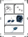
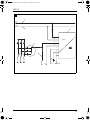

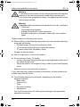
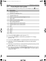
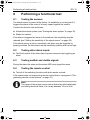
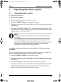
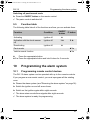

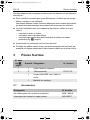
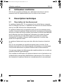
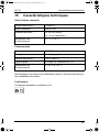

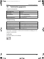
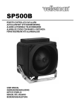
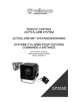
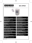

![[ Bedienungsanleitung ]](http://vs1.manualzilla.com/store/data/006735880_1-28334984de48ae2c5a8573c29f433271-150x150.png)