1
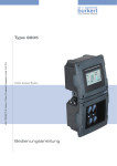
Type 8228
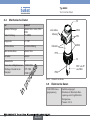
Inductive conductivity meter
Induktives Leitfähigkeits-Messgerät
Conductimètre inductif
Quickstart
English
Deutsch
Français
We reserve the right to make technical changes without notice.
Technische Änderungen vorbehalten.
Sous réserve de modifications techniques.
© Bürkert SAS, 2014-2015
Operating Instructions 1501/01_EU-ML 00565589 / Original FR
Type 8228
Table of contents
1 About the Quickstart.........................................................................4
1.1 Definition of the word "device"....................................................... 4
1.2 Symbols used.................................................................................... 4
2 Intended use.................................................................................................5
3 Basic safety information................................................................5
4 General information............................................................................7
4.1 Manufacturer's address and international contacts.................. 7
4.2 Warranty conditions.......................................................................... 7
4.3 Information on the Internet.............................................................. 7
5 Understanding the name plate..................................................7
6 Technical data............................................................................................8
6.1 Conditions of use.............................................................................. 8
6.2 Conformity to standards and directives....................................... 8
6.3 General technical data..................................................................... 9
6.4 Mechanical data..............................................................................10
6.5 Electrical data..................................................................................10
6.6 Data of the connectors and wires...............................................11
8.2 Installing the device in the pipe....................................................15
8.3 Wiring the device............................................................................16
9 Operating and commissioning................................................. 21
9.1 Safety instructions..........................................................................21
9.2 Using the navigation button..........................................................22
9.3 Using the dynamic functions........................................................24
9.4 Knowing the display.......................................................................24
9.5 Knowing the operating levels.......................................................26
9.6 Choosing the output wiring mode...............................................26
9.7 Calibrating the zero point of conductivity..................................26
9.8 Entering the correction factor of the fitting used.....................27
10Maintenance and troubleshooting................................... 28
10.1 Safety instructions........................................................................28
11Packaging, Transport...................................................................... 28
12Storage.......................................................................................................... 29
13Disposal of the product.............................................................. 29
7 Assembly........................................................................................................ 12
7.1 Safety instructions..........................................................................12
7.2 Unscrewing the cover....................................................................13
7.3 Mounting the display module.......................................................13
8 Installation and wiring.................................................................. 14
8.1 Safety instructions..........................................................................14
English
3
Type 8228
About the Quickstart
1
About the Quickstart
The Quickstart includes main information and instructions for using
the device.
The complete description of the device is in the operating instructions of the device.
Please keep this Quickstart in a safe place, accessible to all users
and any new owners.
Important safety information.
Fully read the Quickstart. In particular, observe the safety recommendations and intended use.
▶▶ The quickstart must be read and understood.
The full operating instructions are on the CD delivered with
the device and on the internet at: www.burkert.com
1.1
Definition of the word "device"
The word "device" used within this manual refers to the conductivity
meter type 8228.
1.2
Symbols used
The following symbols are used in this manual.
danger
Warns against an imminent danger.
▶▶ Failure to observe this warning can result in death or in serious
injury.
4
English
Warning
Warns against a potentially dangerous situation.
▶▶ Failure to observe this warning can result in serious injury or
even death.
CAUTION
Warns against a possible risk.
▶▶ Failure to observe this warning can result in substantial or minor
injuries.
note
Warns against material damage.
Important advice or recommendations.
Refers to information contained in this manual or in other
documents.
→→Indicates a procedure to be carried out.
Type 8228
Intended use
2
Intended use
Use of the device that does not comply with the instructions
could present risks to people, nearby installations and the
environment.
The 8228 conductivity meter is intended solely for the measurement of the conductivity.
▶▶ This device must be used in compliance with the characteristics
and commissioning and use conditions specified in the contractual documents and in the user manual.
▶▶ This device must be protected against electromagnetic interference, ultraviolet rays and, when installed outdoors, the effects of
climatic conditions.
▶▶ Only use a device in perfect operating condition.
▶▶ Correctly store, transport, install and use the device.
▶▶ Only use the device as intended.
▶▶ Observe any existing restraints when the device is exported.
3
Basic safety information
This safety information does not take into account:
• any contingencies or occurences that may arise during installation,
use and maintenance.
• the local safety regulations for which the operating company is responsible including the staff in charge of installation and maintenance.
Risk of injury due to high pressure in the installation.
▶▶ Stop the circulation of fluid, cut off the pressure and drain the
pipe before loosening the process connections.
Risk of injury due to electrical voltage.
▶▶ Shut down the electrical power source of all the conductors and
isolate it before carrying out work on the system.
▶▶ All equipment connected to the 8619 shall be double insulated with respect to the mains according to the standard IEC
61010-1:2010.
▶▶ Observe all applicable accident protection and safety regulations for electrical equipment.
Risk of injury due to high fluid temperatures.
▶▶ Use safety gloves to handle the device.
▶▶ Stop the circulation of fluid and drain the pipe before loosening
the process connections.
Risk of injury due to the nature of the fluid.
▶▶ Respect the regulations on accident prevention and safety relating to the use of aggressive fluids.
English
5
Type 8228
Basic safety information
Various dangerous situations
To avoid injury take care to:
▶▶ not to use the device in explosive atmospheres.
▶▶ not to use the device in an environment incompatible with the
materials it is made of.
▶▶ not to use the device for the measurement of the conductivity of
gases.
▶▶ not to subject the device to mechanical loads (e.g. by placing
objects on top of it or by using it as a step).
▶▶ not to make any external or internal modifications to the device.
▶▶ to prevent any unintentional power supply switch-on.
▶▶ to ensure that installation and maintenance work are
carried out by qualified, authorised personnel in possession of
the appropriate tools.
▶▶ to guarantee a defined or controlled restarting of the process,
after a power supply interruption.
▶▶ to use the device only if in perfect working order and in compliance with the instructions provided in the operating instructions.
▶▶ to observe the general technical rules when installing and using
the device.
6
English
note
The device may be damaged by the fluid in contact with.
▶▶ Systematically check the chemical compatibility of the component materials of the device and the fluids likely to come into
contact with it (for example: alcohols, strong or concentrated
acids, aldehydes, alkaline compounds, esters, aliphatic compounds, ketones, halogenated aromatics or hydrocarbons,
oxidants and chlorinated agents).
note
Elements / Components sensitive to electrostatic discharges
▶▶ This device contains electronic components sensitive to electrostatic discharges. They may be damaged if they are touched by
an electrostatically charged person or object. In the worst case
scenario, these components are instantly destroyed or go out of
order as soon as they are activated.
▶▶ To minimise or even avoid all damage due to an electrostatic
discharge, take all the precautions described in the EN 61340-5-1
norm.
▶▶ Do not touch any of the live electrical components.
Type 8228
General information
4
4.1
General information
5
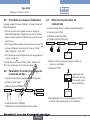
Manufacturer's address and
international contacts
1 2
To contact the manufacturer of the device, use following address:
Bürkert SAS
Rue du Giessen
BP 21
F-67220 TRIEMBACH-AU-VAL
You may also contact your local Bürkert sales office.
The addresses of our international sales offices are available on the
internet at:
17
16
15
14
13
12
11
www.burkert.com
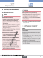
4.2
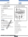
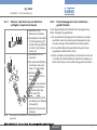
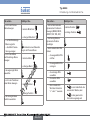
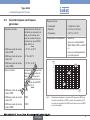
Understanding the name
plate
3
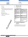
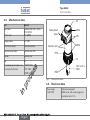
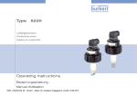
8228 Inductive Conductivity Meter
Supply: 12-36V
40W max.
Output: 1x4-20mA 1xTrans 700mA max.
Cell: PEEK Range 100 µS/cm - 2 S/cm
Process: Temp -15 to 130°C
PN 10, limited by fitting material and fluid temp.
IP65-IP67
Fig. 1:
00566615
8
1:V+
4:I1
9
Name plate of the device (example)
The condition governing the legal warranty is the conforming use of
the device in observance of the operating conditions specified in this
manual.
2. Type of the device
4.3
3. Measurable variable
Information on the Internet
3:0V
S-N:1000
10
Warranty conditions
2:NPN/PNP1
W41MN
4
5
6
7
1. Supply voltage
You can find the user manuals and technical data sheets regarding
the type 8228 at:
4. Max. power consumption
www.burkert.com
6. Conductivity measuring range
5. Max. current available at the transistor output(s)
7. Fluid temperature range
8. Pin assignment of the M12 fixed connector(s)
9. Conformity logos
English
7
Type 8228
Technical data
10.Order code
6
11.Serial number
12.Warning: Before using the device, take into account the technical specifications described in these operating instructions.
6.1
Technical data
Conditions of use
Ambient temperature
-10 to +60 °C
13.Protection class
Air humidity
< 85 %, non condensated
14.Construction code
Height above see level
max. 2000 m
15.Nominal pressure of the fluid
Installation category acc. to
UL 61010-1
Category I
Degree of pollution acc. to
EN 61010-1
Degree 2
Protection class acc. to
EN 60529
IP65 and IP67 with connectors
plugged in and tightened and
electronic module cover fully
screwed down
16.Material of the conductivity sensor holder
17. Available outputs
6.2
Conformity to standards and
directives
The EC directives and the standards the device conforms to are
listed in the EC declaration of conformity for the type 8228.
8
English
Type 8228
Technical data
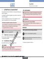
6.3
General technical data
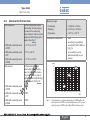
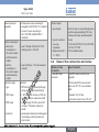
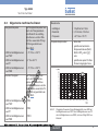
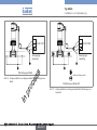
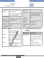
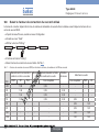
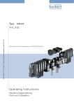
Fluid temperature
The fluid temperature may be
restricted by the fluid pressure,
the material the conductivity
sensor holder is made of and the
material the S020 fitting used is
made of. See Fig. 2".
• 8228 with conductivity sensor
in PVDF
• -15 °C to +100 °C
• 8228 with conductivity sensor
in PP
• 0 °C to +80 °C
• 8228 with conductivity sensor
in PEEK
Fluid pressure
• -15 °C to +130 °C
• 8228 with conductivity sensor
in PVDF
• PN6
• 8228 with conductivity sensor
in PP
• PN6
• 8228 with conductivity sensor
in PEEK
• PN10
Measuring ranges
• Conductivity
• 100µS/cm to 2 S/cm
• Resistivity
• 0,5 W/cm to 10 kW/cm
• Temperature
• -40 °C to +150 °C
Temperature compensation
• none
• according to a predefined
curve (NaCl, NaOH, HNO3 or
H2SO) or
• or according to a curve
defined especially for your
process
P (bar)
12
11
10
9
8
7
6
5
4
3
2
1
0
The fluid pressure may be
restricted by the fluid temperature, the material the conductivity sensor holder is made of
and the material the S020 fitting
used is made of. See Fig. 2".
Fig. 2:
PEEK
PVDF
PP
-20
0
+20 +40 +60 +80 +100 +120 +140
T (°C)
Fluid temperature - pressure dependency for a 8228 with a conductivity sensor in PVDF or a conductivity sensor in PP or a conductivity sensor in PEEK, with a fitting S020 in stainless steel
English
9
Type 8228
Technical data
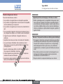
6.4
Mechanical data
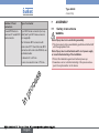
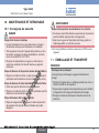
Part
Box / seals
Cover / seal
Material
stainless steel 316L 1.4404,
PPS / EPDM
PC / EPDM
Display module
PC / PBT
M12 fixed connector
nickel-plated brass
Fixed connector holder
stainless steel 316L
Screws
stainless steel
Nut
PC
Conductivity sensor holder / seal
in contact with the fluid
• PVDF / FKM
PC
Nickel-plated
brass
EPDM
PPS
EPDM
Stainless steel
PPS
PC
• PP / FKM
PVDF or PP or
PEEK
FKM
• PEEK / FKM
Fig. 3:
Materials of the device
6.5
Electrical data
Power supply
12-36 V DC
• filtered and regulated
• SELV circuit, with a safe energy level
• oscillation rate: ±10 %
10
English
Type 8228
Technical data
Power source (not
supplied)
• limited power source according to
paragraph 9.3 of EN 61010-1 standard
• or class 2 source according to
UL 1310/1585 and EN 60950-1
standards
Current consumption
• without the
consumption of
the current outputs
and the transistor
outputs
• max. 1 W (max. 25 mA at 12 V DC;
starting current ~100 mA)
• with the
consumption of
the current outputs
and the transistor
outputs
Transistor output
• max. 40 W (max. 1 A for the transistor
outputs)
• type
• NPN (/sink) or PNP(/source) (through
wiring and through parameterizing)
• NPN output
• 1-36 V DC, 700 mA max. (or 500 mA
max. if 2 transistor outputs are wired)
• PNP output
• supply voltage, 700 mA max. (or 500
mA max. if 2 transistor outputs are
wired)
• protection
• galvanically insulated, protected against
overvoltages, polarity reversals and
short-circuits
polarized
Current output
• specification
• 4-20 mA, sink or source (through wiring
and through parametrizing), 22 mA to
indicate a fault (can be parametered)
• type of connection
• 3-wire
• max. loop
impedance
• 1100 W at 36 V DC, 610 W at 24 V DC,
100 W at 12 V DC
• Response time (10
% - 90 %)
• 150 ms (default value)
6.6
Data of the connectors and wires
Number of fixed
connectors
1 male M12 fixed
connector
Type of connector
5-pin M12 female connector (not
supplied).
For the female M12 connector with
order code 917116, use a shielded
cable:
• diameter: 3 to 6.5 mm
• wire cross section: max. 0.75 mm2
English
11
Type 8228
Assembly
Number of fixed
connectors
1 male M12 fixed connector and 1 female M12
fixed connector
Type of connector
5-pin M12 female connector (not supplied) and 5-pin M12 male connector
(not supplied).
For the female M12 connector with
order code 917116 and the male M12
connector with order code 560946, use
a shielded cable:
• diameter: 3 to 6.5 mm
• wire cross section: max. 0.75 mm2
12
English
7
7.1
Assembly
Safety instructions
Warning
Risk of injury due to non-conforming assembly.
▶▶ The device must only be assembled by qualified and skilled staff
with the appropriate tools.
Risk of injury due to unintentional switch on of power supply
or uncontrolled restarting of the installation.
▶▶ Protect the installation against unintentional power-up.
▶▶ Guarantee a set or controlled restarting of the process subsequent to any intervention on the device.
Type 8228
Assembly
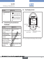
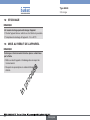
7.2
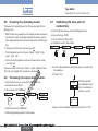
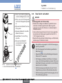
7.3
Unscrewing the cover
Mounting the display module
note
→→Unscrew the cover (see
20°
The tightness of the device is not guaranteed when the cover
is removed.
▶▶ Prevent the projection of liquid inside the housing.
chap. 7.2).
→→Set
the display module
at an angle of ca. 20° in
relation to the desired
position.
The device may be damaged if a metal component comes
into contact with the electronics.
▶▶ Prevent contact of the electronics with a metal component
(screwdriver, for example).
→→The
display module can
be fitted in 4 different
positions, at 90° intervals.
→→To unscrew the cover,
use your hand or a tool
which can be used as
a lever, taking care not
to scratch the glass.
→→Turn
the cover until
fully unscrewed.
a)
c)
b)
d)
→→Fully push in the display
module and turn to the
right to lock it.
Fig. 4:
Unscrewing the cover
Fig. 5:
Mounting the display module
English
13
Type 8228
Installation and wiring
8
8.1
Installation and wiring
Safety instructions
Danger
Danger due to electrical voltage.
▶▶ Shut down the electrical power source of all the conductors and
isolate it before carrying out work on the system.
▶▶ All equipment connected to the 8619 shall be double insulated with respect to the mains according to the standard IEC
61010-1:2010.
▶▶ Observe all applicable accident protection and safety regulations for electrical equipment.
Risk of injury due to high pressure in the installation.
▶▶ Stop the circulation of fluid, cut off the pressure and drain the
pipe before loosening the process connections.
Risk of injury due to high fluid temperatures.
▶▶ Use safety gloves to handle the device.
▶▶ Stop the circulation of fluid and drain the pipe before loosening
the process connections.
Risk of injury due to the nature of the fluid.
▶▶ Respect the regulations on accident prevention and safety relating to the use of aggressive fluids.
Warning
Risk of injury due to non-conforming installation.
▶▶ The electrical installation can only be carried out by qualified and
skilled staff with the appropriate tools.
▶▶ The electrical and fluid installation can only be carried out by
qualified and skilled staff with the appropriate tools.
▶▶ Install appropriate safety devices (correctly rated fuse and/or
circuit-breaker).
▶▶ Observe mounting instructions of the fitting.
Risk of injury due to unintentional switch on of power supply
or uncontrolled restarting of the installation.
▶▶ Protect the installation against unintentional power-up.
▶▶ Guarantee a set or controlled restarting of the process subsequent to any intervention on the device.
Warning
Risk of injury if the fluid pressure/temperature dependency is
not respected.
▶▶ Observe the fluid temperature-pressure dependency according to
the material of the conductivity sensor holder (see the technical data
of the device) and according to the materials the fitting is made of
(see the operating instructions of the fitting used).
▶▶ Observe the Pressure Directive 97/23/CE.
Protect this device against electromagnetic interference,
ultraviolet rays and, when installed outdoors, the effects of the
climatic conditions.
14
English
Type 8228
Installation and wiring
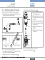
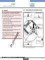
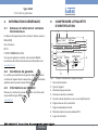
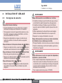
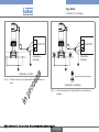
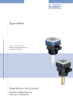
8.2
Installing the device in the pipe
The device is put into a fitting S020 mounted on the pipe.
→→Mount the fitting on the pipe obeying the instructions of the
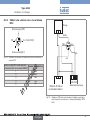
→→Put the device into the fitting, as shown in Fig. 8:
→→Make sure the seal (mark 2) is on
the conductivity sensor.
→→Make sure the material of the seal
operating instructions of the fitting used.
1
is compatible with the fluid to be
measured.
→→Put the nut (mark 5) on the fitting.
→→Put the snap ring (mark 3) into the
groove (mark 4).
2
→→Engage the device (mark 1) into
the fitting.
→→Screw the nut (mark 5) manually
on the device.
Fig. 6:
Positions for the mounting on the pipe
3
4
Tank without mixing
device
Fig. 7:
Tank with mixing device
Positions for the mounting on a container
→→Fit the display module (see chap. 7.3) to calibrate the conduc-
5
Fig. 8:
Installation of the device into the S020 fitting
→→Wire acc. to instructions in chap. 8.3.
tivity sensor and to parameter the device.
→→Calibrate the zero point of conductivity (see chap. 9.7).
English
15
Type 8228
Installation and wiring
Wiring the device
danger
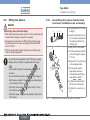
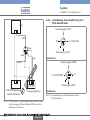
8.3.1 Assembling the male or female fixed
connector (available as an accessory)
→→Unscrew the nut [1] on the
Risk of injury due to electrical voltage.
▶▶ Shut down the electrical power source of all the conductors and
isolate it before carrying out work on the system.
▶▶ All equipment connected to the 8619 shall be double insulated with respect to the mains according to the standard IEC
61010-1:2010.
▶▶ Observe all applicable accident protection and safety regulations for electrical equipment.
4
body [4].
→→Cut the central wire (earth)
so that its length is equal to
11.5 mm.
5,5
→→Expose 5.5 mm of the wires
on the stripped cable.
→→Put each wire into the
appropriate terminal of
the terminal block [5] (see
chap. 8.3.3 or 8.3.4).
• Do not install theconnection cables near high voltage or
high frequency cables; If this cannot be avoided, observe
a min. distance of 30 cm.
→→Tighten the terminal block
• Protect the power supply of the device with a 100 mA
time-delay fuse and a switch.
→→Tighten the connector nut
• Protect the power supply of each transistor output with a
750 mA fuse.
16
1
[1], the cable clamp [2] and
the seal [3], and then into
the body [4].
→→Strip 20 mm of the cable.
5
,5
11
• Use shielded cables with a temperature limit of 80 °C
minimum.
2
→→Insert the cable into the nut
• Use a filtered and regulated 12-36 V DC power supply.
• Make sure the installation is equipotential. See chap.
8.3.2.
3
20
8.3
English
[5] wired to the body [4].
[1].
Fig. 9:
Assembling the M12 multi-pin connector (not provided)
Type 8228
Installation and wiring
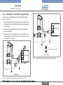
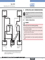
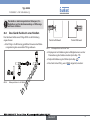
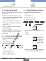
8.3.2 Making the installation equipotential
To ensure the equipotentiality of the installation (power supply device - medium):
→→Connect together the various earth spots in the installation to
eliminate the potential differences that may occur between different earthes.
+
→→Observe faultless earthing of the shield of the power supply
12-36 V DC
cable, at both ends.
→→If the device is installed on plastic pipes, earth together the
metallic instruments such as pumps or valves, that are as close
as possible to the device.
Power supply
Devices such as valves, pumps,...
+
12-36 V DC
Plastic pipe
Fig. 11: Equipotentiality skeleton diagram with pipes in plastic
Power supply
Metal pipe
Fig. 10: Equipotentiality skeleton diagram with pipes in metal
English
17
Type 8228
Installation and wiring
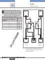
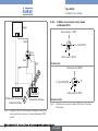
8.3.3 Wiring a version with a single M12
fixed connector
Load
Transistor output (TR1)
white
2
0V
1
3
V+ (12-36 V DC)
2
blue
4
3
brown
4
1
Current output (AC1)
grey
Fig. 12: Pin assignment of the male fixed connector on a version with a
single M12 fixed connector
Pin of the M12 female cable available as an
Colour of the wire
accessory (order code 438680)
1
brown
2
white
3
blue
4
black
grey
5
black
- +
- +
12-36 V DC
4-20 mA input at
external instrument
Power supply
Fig. 13: NPN wiring of the transistor output and and wiring in sinking mode
of the current output of a version with 1 fixed connector (parameter
setting "NPN/sink")
18
English
Type 8228
Installation and wiring
8.3.4 Wiring a version with 2 M12 fixed
connectors
Load
Transistor output 1 (TR1)
2
white
0V
2
3
blue
1
3
4
brown
4
V+ (12-36 V DC)
1
Current output 1 (AC1)
grey
black
Male fixed connector
Transistor output 2 (TR2)
2
V+ (12-36 V DC)
- +
Power supply
3
0V
4
- +
Current output 2 (AC2)
12-36 V DC
4-20 mA input at external instrument
1
Female fixed connector
Fig. 15: Pin assignment of the male and female M12 fixed connectors
Fig. 14: PNP wiring of the transistor output and and wiring in sourcing
mode of the current output of a version with 1 fixed connector
(parameter setting "PNP/source")
English
19
Type 8228
Installation and wiring
Connect the power supply for the device to the male
fixed connector; the supply is then transferred internally
to pins 1 and 3 of the female fixed connector in order to
ease wiring of the load to the female fixed connector.
Load 1
Pin of the female or male M12 cables available
Colour of the
as accessories (order code 438680 respecwire
tively 559177)
1
brown
2
white
3
blue
4
black
grey
5
Load 2
white
white
2
blue
3
brown
4
2
brown
1
1
4
3
black
black
grey
- +
- +
- +
12-36 V DC
1st 4-20 mA input
at external instrument
Power supply
2nd 4-20 mA
input at external
instrument
Fig. 16: NPN wiring of both transistor outputs and wiring of both current
outputs in sinking mode, on a version with 2 fixed connectors
(parameter setting "NPN/sink")
20
English
Type 8228
Operating and commissioning
9
Load 1
Load 2
• The settings can only be done on a device with a display
module.
• Do not remove the display module while making the settings on the device.
white
9.1
white
blue
2
3
2
brown
4
1
1
4
blue
Risk of injury due to non-conforming operating.
3
black
grey
- +
Safety instructions
Warning
black
- +
Operating and commissioning
Non-conforming operating could lead to injuries and damage the
device and its surroundings.
▶▶ The operators in charge of operating must have read and understood the contents of this manual.
▶▶ In particular, observe the safety recommendations and intended
use.
▶▶ The device/installation must only be operated by suitably trained
staff.
- +
12-36 V DC
1st 4-20 mA input
at external instrument
Power supply
2nd 4-20 mA
input at external
instrument
Fig. 17: PNP wiring of both transistor outputs and wiring of both current
outputs in sourcing mode, on a version with 2 fixed connectors
(parameter setting "PNP/source")
English
21
Type 8228
Operating and commissioning
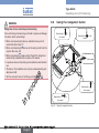
9.2
Warning
Using the navigation button
Symbolised by
this manual
in
Danger due to non-conforming commissioning.
Non-conforming commissioning could lead to injuries and damage
the device and its surroundings.
▶▶ Before commissioning the device, calibrate the zero point of
conductivity. See chap. 9.7.
▶▶ Before commissioning the device, set the wiring mode for all the
outputs. See chap. 9.6.
▶▶ Before commissioning, make sure that the staff in charge have
read and fully understood the contents of the manual.
▶▶ In particular, observe the safety recommendations and intended
use.
▶▶ The device / the installation must only be commissioned by suitably trained staff.
▶▶ Set the correction factor of the fitting used. See chap. 9.8.
Symbolised by
manual
in this
Symbolised by
in this manual
Symbolised by
in this manual
Symbolised by
this manual
in
Fig. 18: Using the navigation button
22
English
Type 8228
Operating and commissioning
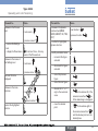
You want to...
Press...
...browse in the Process
level
• next screen:
• ...display the Param menu
...browse in the menus of
the Settings level
for at least 2 sec., from any
screen of the Process level
• next menu:
• previous menu:
...browse in the menu
functions
...access the menu
displayed
• next function:
• previous function:
...select the highlighted
function
Press...
...browse in the dynamic
functions bar (MEAS,
BACK, ABORT, OK, YES,
NO)
...confirm the highlighted
dynamic function
• next function:
• previous function:
• previous screen:
• ...access the Settings
level
You want to...
...modify a numerical value
-- increment the figure
selected
--
-- decrement the figure
selected
--
-- select the previous
figure
-- select the next figure
--
-- allocate the "+" or "-"
sign to the numerical
value
--
-- move the decimal
point
--
-to the extreme left of the
numerical value then
until the desired sign is displayed
to the extreme right of
the numerical value then
until the decimal point is in the
desired place
English
23
Type 8228
Operating and commissioning
9.3
Using the dynamic functions
You want to...
Choose...
...go back to the Process level,
without confirming the modifications made
...validate the input
...go back to the parent menu
... abort the current operation
and go back to the parent menu
...answer the question asked
dynamic function "MEAS"
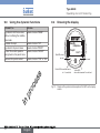
9.4
Knowing the display
dynamic function "OK"
dynamic function "BACK"
dynamic function "ABORT"
dynamic function "YES" or "NO"
LO
CK
EN
OP
CondS
0.000µS/cm
TempC
Red LED: shows
an error
ERR
Yellow LED: shows that transistor 1 is switched
23.8 °C
not used
Yellow LED:
shows that transistor 2 is switched
Fig. 19: Position of the symbols and description of the LEDs on the display
module
24
English
Type 8228
Operating and commissioning
Icon
Yellow LED: shows that
transistor 1 is switched
Meaning and alternatives
Sensor in good condition, fluid conductivity and fluid
temperature within the set ranges.
Green LED: shows that
the device is energized
If the monitoring of the conductivity and/or the fluid temperature and/or the fluid conductivity has been activated,
the alternative icons in this position are:
:
, associated with
•
ERR
, associated with
:
•
The device is measuring.
The alternative icons in this position are:
Yellow LED: shows that
transistor 2 is switched
!
Red LED: shows an error
flashing: function HOLD is active
T
• : running check that the outputs are working and
behaving correctly
"maintenance" message
•
Fig. 20: Description of the LEDs on the electronic board
The LEDs of the display module are duplicated on the electronic board that is located under the display module: these
LEDs can only be seen if the device has no display module.
HOLD
"warning" message
ERR
"error" message
English
25
Type 8228
Operating and commissioning
9.5
Knowing the operating levels
The device has 2 operating levels: the Process level and the Configuration level.
• When the device is powered up or the display module mounted on
the electronic module, the display indicates the software version
of the display module then it shows the first screen of the Process
level.
→→To browse in the Process level, see chap. 9.2.
9.7
Calibrating the zero point of
conductivity
→→From the Process level, access the Configuration level.
→→Access the menu "Calib".
→→Got to the function "Zero Calib.".
→→Confirm the function "Zero Calib.".
Calib
Sensor
• The Configuration level has 5 menus: „Param“, „Calib“, „Diagnostic“, „Test“, „Info“.
see chap. 9.2.
9.6
Choosing the output wiring mode
→→From the Process level, access the Configuration level.
→→Access the menu "Param".
→→Go to the function "HWMode".
Param
HWMode
Outputs
This is
when the
device is being parametered............
....................
→→Confirm the function "HWMode".
→→Choosing the wiring mode for all the outputs.
26
English
→→Put the cleaned and dried conductivity sensor in contact with
the ambient air.
→→Choose “Yes”.
Processing
source/PNP
sink/NPN
This is
when the
device is being parametered............
....................
Zero Calib.
Calibrate Zero
Point?
→→To access the Configuration level and to browse in the menus,
The access codes to the menus „Param“, „Calib“, „Diagnostic“ and
„Test“ are only required if they have been customized.
Probe
The device automatically calibrates the zero
point of conductivity in
less than 1 second.
Save modified
data?
→→Save or not the calibration result by choosing "Yes" or "No".
Type 8228
Operating and commissioning
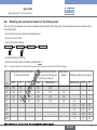
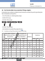
9.8
Entering the correction factor of the fitting used
The correction factor depends on the shape, the material and the diameter of the fitting used. The following table gives the correction factors
of the fittings S020.
→→From the Process level, access the Configuration level.
→→Access the menu "Calib".
→→Go to the function "K-fitting".
Calib
Sensor
Probe
K-fitting
→→Confirm the function "K-fitting".
→→Enter the correction factor of the fitting used.See Table 1.
Table 1: Correction factors of the fittings S020, depending on the shape, the material and the DN of the fittings
Fittings with true union connections
or fittings with weld ends
DN
<32
Fittings with internal or external
thread connections or fittings with
weld end connections
PVDF
PP
PVC
Brass
Stainless steel
1,08
1,08
1,08
0,99
0,99
Measurement
chamber
Welding sockets or fusion spigots
Stainless steel
PVDF
PP
-
-
-
-
32
1,08
1,08
1,08
0,99
0,99
0,99
-
-
-
40
1,04
1,04
1,04
0,99
0,99
0,99
-
-
-
50
1,02
1,02
1,02
0,99
0,99
0,99
0,99
-
-
65
-
-
-
-
-
-
0,99
1,02
1,02
80
-
-
-
-
-
-
0,99
1,02
1,02
100
-
-
-
-
-
-
1,00
1,02
1,02
>100
-
-
-
-
-
-
1,00
1,00
1,00
English
27
Type 8228
Maintenance and troubleshooting
10 Maintenance and
troubleshooting
10.1 Safety instructions
danger
Danger due to electrical voltage.
▶▶ Shut down the electrical power source of all the conductors and
isolate it before carrying out work on the system.
▶▶ All equipment connected to the 8619 shall be double insulated with respect to the mains according to the standard IEC
61010-1:2010.
▶▶ Observe all applicable accident protection and safety regulations for electrical equipment.
Risk of injury due to high pressure in the installation.
▶▶ Stop the circulation of fluid, cut off the pressure and drain the
pipe before loosening the process connections.
Risk of injury due to high fluid temperatures.
▶▶ Use safety gloves to handle the device.
▶▶ Stop the circulation of fluid and drain the pipe before loosening
the process connections.
Risk of injury due to the nature of the fluid.
▶▶ Respect the regulations on accident prevention and safety relating to the use of aggressive fluids.
28
English
Warning
Risk of injury due to non-conforming maintenance.
▶▶ Maintenance must only be carried out by qualified and skilled
staff with the appropriate tools.
▶▶ Ensure that the restart of the installation is controlled after any
interventions.
→→If there is a problem, see the operating instructions on the CD
delivered with the device.
11 Packaging, Transport
note
Damage due to transport
Transport may damage an insufficiently protected device.
▶▶ Transport the device in shock-resistant packaging and away
from humidity and dirt.
▶▶ Do not expose the device to temperatures that may exceed the
admissible storage temperature range.
▶▶ Protect the electrical interfaces using protective plugs.
Type 8228
Storage
12 Storage
note
Poor storage can damage the device.
▶▶ Store the device in a dry place away from dust.
▶▶ Storage temperature of the device: -10 to +60 °C.
13 Disposal of the product
note
Damage to the environment due to parts contaminated by the
fluid.
• Dispose of the device and its packaging in an environmentallyfriendly way.
• Comply with the regulations which concern the area of waste
disposal.
English
29
Type 8228
Storage
30
English
Typ 8228
Inhaltsverzeichnis
1 Über den Quickstart............................................................................4
1.1 Begriffsdefinition "Gerät"................................................................. 4
1.2 Darstellungsmittel.............................................................................. 4
2 Bestimmungsgemässe Verwendung.......................................5
3 Grundlegende Sicherheitshinweise.....................................5
4 Allgemeine hinweise..............................................................................7
4.1 Kontaktadressen................................................................................ 7
4.2 Gewährleistung................................................................................. 7
4.3 Informationen im Internet................................................................. 7
5 Das Typschild verstehen.................................................................7
6 Technische Daten....................................................................................8
6.1 Betriebsbedingungen....................................................................... 8
6.2 Einhaltung von Normen und Richtlinien....................................... 8
6.3 Allgemeine technische Daten......................................................... 9
6.4 Mechanische Daten........................................................................10
6.5 Elektrische Daten............................................................................10
6.6 Daten der Stecker und Kabel.......................................................11
8.2 Das Gerät fluidisch anschließen..................................................15
8.3 Das Gerät verkabeln.......................................................................16
9 Einstellung und Inbetriebnahme.......................................... 22
9.1 Sicherheitshinweise........................................................................22
9.2 Verwendung des Navigationstaste..............................................23
9.3 Verwendung der dynamischen Funktionen...............................25
9.4 Das Display kennen........................................................................25
9.5 Die Bedienebenen kennen............................................................27
9.6 Anschlussart der Ausgänge wählen...........................................27
9.7 Nullpunkt-Kalibrierung durchführen............................................27
9.8 Den Korrekturfaktor des verwendeten Fittings eingeben. ....28
10Wartung, Fehlerbehebung.......................................................... 29
10.1 Sicherheitshinweise.....................................................................29
11Verpackung, Transport.................................................................. 29
12Lagerung....................................................................................................... 30
13Entsorgung des Geräts................................................................ 30
7 Montage......................................................................................................... 12
7.1 Sicherheitshinweise........................................................................12
7.2 Abschrauben des Deckels............................................................13
7.3 Displaymodul anbringen................................................................13
8 Installation und Verkabelung................................................ 14
8.1 Sicherheitshinweise........................................................................14
deutsch
3
Typ 8228
Über den Quickstart
1
Über den Quickstart
Warnung!
Der Quickstart enthält in Kurzform die wichtigsten Informationen und
Hinweise für den Gebrauch des Gerätes.
Die ausführliche Beschreibung finden Sie in der Bedienungsanleitung für das Gerät.
Bewahren Sie diese Anleitung so auf, dass sie für jeden Benutzer
zugänglich ist und jedem neuen Eigentümer des Gerätes wieder zur
Verfügung steht.
Wichtige Informationen zur Sicherheit!
Lesen Sie den Quickstart sorgfältig durch. Besonders zu
beachten sind die Sicherheitshinweise und die bestimmungsgemäße Verwendung.
▶▶ Der Quickstart muss gelesen und verstanden werden.
Die Bedienungsanleitung finden Sie auf der beigelegten CD
oder im Internet unter: www.buerkert.de
1.1
Begriffsdefinition "Gerät"
Der in dieser Anleitung verwendete Begriff "Gerät" steht immer für
das induktive Leitfähigkeits-Messgerät Typ 8228.
1.2
Darstellungsmittel
In dieser Anleitung werden folgende Darstellungsmittel verwendet.
Gefahr!
Warnt vor einer unmittelbaren Gefahr!
▶▶ Bei Nichteinhaltung sind Tod oder schwere Verletzungen die
Folge.
4
deutsch
Warnt vor einer möglicherweise gefährlichen Situation!
▶▶ Bei Nichteinhaltung drohen schwere Verletzungen oder Tod.
Achtung!
Warnt vor einer möglichen Gefährdung!
▶▶ Nichtbeachtung kann mittelschwere Verletzungen oder leichte
Verletzungen zu Folge haben.
Hinweis
Warnt vor Sachschäden!
Wichtige Tipps und Empfehlungen.
verweist auf Informationen in dieser Bedienungsanleitung
oder in anderen Dokumentationen.
→→markiert einen Arbeitsschritt, den Sie ausführen müssen.
Typ 8228
Bestimmungsgemässe Verwendung
2
Bestimmungsgemässe
Verwendung
Bei nicht bestimmungsgemäßem Einsatz des Geräts können
Gefahren für Personen, Anlagen in der Umgebung und die
Umwelt entstehen.
Das induktive Leitfähigkeits-Messgerät Typ 8228 darf nur
zur Messung der Leitfähigkeit einer Flüssigkeit eingesetzt
werden.
▶▶ Für den Einsatz sind die in den Vertragsdokumenten und der
Bedienungsanleitung spezifizierten zulässigen Daten, Betriebsund Einsatzbedingungen zu beachten.
▶▶ Das Gerät vor elektromagnetischen Störungen, U.V.-Bestrahlung und bei Außenanwendung vor Witterungseinflüssen
schützen.
▶▶ Das Gerät nur in einwandfreiem Zustand betreiben.
▶▶ Auf sachgerechte Lagerung, Transport, Installation und Bedienung des Gerätes achten.
▶▶ Dieses Gerät nur bestimmungsgemäß einsetzen.
▶▶ Beachten Sie bei der Ausfuhr des Gerätes gegebenenfalls bestehende Beschränkungen.
3
Grundlegende
Sicherheitshinweise
Diese Sicherheitshinweise berücksichtigen keine
• Zufälligkeiten und Ereignisse, die bei Montage, Betrieb und Wartung
auftreten können.
• Ortsbezogenen Sicherheitsbestimmungen, für deren Einhaltung,
auch in Bezug auf das Installations- und Wartungspersonal, der
Betreiber verantwortlich ist.
Verletzungsgefahr durch hohen Druck in der Anlage!
▶▶ Vor dem Lösen der Prozessanschlüsse die Anlage druckfrei
schalten und die Flüssigkeitszirkulation stoppen.
Verletzungsgefahr durch Stromschlag!
▶▶ Schalten Sie vor Beginn der Arbeiten in jedem Fall alle existierenden
am Gerät angeschlossenen Spannungs-Versorgungen ab, und
sichern Sie diese vor unbeabsichtigtem Wiedereinschalten!
▶▶ Jedes am Gerät angeschlossene Instrument muss gegenüber
dem elektrischen Verteilungsnetz gemäß der Norm 610101:2010 doppelt isoliert sein.
▶▶ Beachten Sie die geltenden Unfallverhütungs- und Sicherheitsbestimmungen für elektrische Geräte!
Verletzungsgefahr durch hohe Flüssigkeitstemperaturen!
▶▶ Das Gerät nur mit Schutzhandschuhen anfassen.
▶▶ Vor dem Lösen der Prozessanschlüsse die Flüssigkeitszirkulation stoppen und die Rohrleitung leer laufen lassen.
deutsch
5
Typ 8228
Grundlegende Sicherheitshinweise
Hinweis:
Verletzungsgefahr aufgrund der Art der Flüssigkeit!
▶▶ Beachten Sie die Regeln, die auf dem Gebiet der Unfallverhütung und der Sicherheit in Kraft sind und die sich auf die
Verwendung gefährlicher Produkte beziehen.
▶▶ Dieses Gerät nicht in explosionsgefährdeten Bereichen einsetzen.
▶▶ Dieses Gerät nicht in einer Umgebung verwenden, die mit den
Materialien, aus denen es besteht, inkompatibel ist.
▶▶ Dieses Gerät nicht für die Leitfähigkeitsmessung von Gas
einsetzen.
▶▶ Belasten Sie das Gerät nicht mechanisch (z. B. durch Ablage
von Gegenständen oder als Trittstufe).
▶▶ Nehmen Sie keine äußerlichen oder innerlichen Veränderungen
am Gerät vor.
▶▶ dass die Anlage nicht unbeabsichtigt betätigt werden kann.
▶▶ Installations- und Instandhaltungsarbeiten dürfen nur von autorisiertem Fachpersonal mit geeignetem Werkzeug ausgeführt
werden.
▶▶ Nach einer Unterbrechung der elektrischen Versorgung ist ein
definierter oder kontrollierter Wiederanlauf des Prozesses zu
gewährleisten.
▶▶ Betreiben Sie das Gerät nur in einwandfreiem Zustand und
unter Beachtung der Bedienungsanleitung.
▶▶ Bei der Einsatzplanung und dem Betrieb des Gerätes die allgemeinen Regeln der Technik einhalten.
6
deutsch
Das Gerät kann durch das Medium beschädigt werden.
▶▶ Kontrollieren Sie systematisch die chemische Verträglichkeit der
Werkstoffe, aus denen das Gerät besteht und der Flüssigkeiten,
die mit diesem in Berührung kommen können (zum Beispiel:
Alkohole, starke oder konzentrierte Säuren, Aldehyde, Basen,
Ester, aliphatische Verbindungen, Ketone, aromatische oder
halogenierte Kohlenwasserstoffe, Oxidations- bzw. chlorhaltige
Mittel).
Hinweis:
Elektrostatisch gefährdete Bauelemente / Baugruppen!
▶▶ Das Gerät enthält elektronische Bauelemente, die gegen elektrostatische Entladung (ESD) empfindlich reagieren. Berührung
mit elektrostatisch aufgeladenen Personen oder Gegenständen
gefährdet diese Bauelemente. Im schlimmsten Fall werden sie
sofort zerstört oder fallen nach der Inbetriebnahme aus.
▶▶ Die Anforderungen nach EN 61340-5-1 beachten, um die
Möglichkeit eines Schadens durch schlagartige elektrostatische
Entladung zu minimieren bzw. zu vermeiden!
▶▶ Die elektronischen Bauelemente nicht bei anliegender Versorgungsspannung berühren!
Typ 8228
Allgemeine hinweise
4
4.1
Allgemeine hinweise
5
Kontaktadressen
1 2
Der Hersteller des Gerätes kann unter folgender Adresse benachrichtigt werden:
Bürkert SAS
Rue du Giessen
BP 21
F-67220 TRIEMBACH-AU-VAL
oder wenden Sie sich an Ihr lokal zuständiges Vertriebsbüro von
Bürkert.
17
16
15
14
13
12
11
Die internationalen Kontaktadressen finden Sie im Internet unter:
www.burkert.com
4.2
Gewährleistung
Voraussetzung für die Gewährleistung ist der bestimmungsgemäße
Gebrauch des Gerätes unter Beachtung der im vorliegenden
Handbuch spezifizierten Einsatzbedingungen.
4.3
Informationen im Internet
Das Typschild verstehen
3
8228 Inductive Conductivity Meter
Supply: 12-36V
40W max.
Output: 1x4-20mA 1xTrans 700mA max.
Cell: PEEK Range 100 µS/cm - 2 S/cm
Process: Temp -15 to 130°C
PN 10, limited by fitting material and fluid temp.
IP65-IP67
3:0V
S-N:1000
00566615
10
Bild 1:
2:NPN/PNP1
W41MN
4
5
6
7
8
1:V+
4:I1
9
Typschild des Gerätes (Beispiel)
1. Betriebsspannung
2. Typ des Gerätes
3. Gemessene Prozessgröße
4. Maximale Leistungsaufnahme
Bedienungsanleitungen und Datenblätter zum Typ 8228 finden Sie
im Internet unter:
5. Maximal verfügbarer Strom am bzw. an den Transistorausgängen
www.buerkert.de
7. Bereich der Flüssigkeitstemperatur
6. Messbereich der Leitfähigkeit
8. Pin-Belegung der M12-Anschlüsse
9. Konformitäts-Logos
10.Bestell-Nummer
deutsch
7
Typ 8228
Technische Daten
11.Seriennummer
6
12.Warnung: Bevor das Gerät benutzt wird, die in der Bedienungsanleitung beschriebenen technischen Daten berücksichtigen.
6.1
Technische Daten
Betriebsbedingungen
13.Schutzart
Umgebungstemperatur
-10 bis +60 °C
14.Konstruktionscode
Luftfeuchtigkeit
< 85 %, nicht kondensierend
15.Druck der Flüssigkeit
Meereshöhe
max. 2000 m
16.Werkstoff der Armatur des Leitfähigkeits-Sensors
Einbaukategorie nach
UL 61010-1
Kategorie I
Verschmuzungsgrad nach
EN 61010-1
Grad 2
Schutzart nach EN 60529
IP65 und IP67 mit eingesteckten und festgeschraubten
Steckverbindern und dem bis
zum Anschlag festgeschraubten
Deckel des Elektronikmoduls.
17. Verfügbare Ausgänge
6.2
Einhaltung von Normen und
Richtlinien
Die angewandten Normen, mit welchen die Konformität zu den
Richtlinien nachgewiesen wird, sind in der EG-Konformitätserklärung
für den Typ 8228 nachzulesen.
8
deutsch
Typ 8228
Technische Daten
6.3
Allgemeine technische Daten
Flüssigkeitstemperatur
Die Flüssigkeitstemperatur kann
durch den Flüssigkeitsdruck,
den Werkstoff des Leitfähigkeits-Sensors und den Werkstoff des verwendeten Fittings
S020 eingeschränkt sein.
Siehe Bild 2.
• 8228 mit Leitfähigkeitssensor
aus PVDF
• -15 °C bis +100 °C
• 8228 mit Leitfähigkeitssensor
aus PP
• 0 °C à +80 °C
• 8228 mit Leitfähigkeitssensor
aus PEEK
Druck der Flüssigkeit
• -15 °C bis +130 °C
Messbereiche
• Leitfähigkeit
• 100µS/cm bis 2 S/cm
• Resistivität
• 0,5 W/cm bis 10 kW/cm
• Temperatur
• -40 °C bis +150 °C
Temperaturkompensation
• gemäß einer speziell für Ihren
Prozess festgelegten Kurve
P (bar)
12
11
10
9
8
7
6
5
4
3
2
1
0
Der Flüssigkeitsdruck kann
durch die Flüssigkeitstemperatur, den Werkstoff des
Leitfähigkeits-Sensors und den
Werkstoff des verwendeten Fittings S020 eingeschränkt sein.
Siehe Bild 2.
• 8228 mit Leitfähigkeitssensor
aus PVDF
• PN6
• 8228 mit Leitfähigkeitssensor
aus PP
• PN6
• 8228 mit Leitfähigkeitssensor
aus PEEK
• PN10
• keine, oder
• gemäß einer bestimmten
Kompensationskurve (NaCl,
NaOH, HNO3 oder H2SO)
oder
Bild 2:
PEEK
PVDF
PP
-20
0
+20 +40 +60 +80 +100 +120 +140
T (°C)
Flüssigkeits-Temperatur-Druck-Abhängigkeit für einen 8228 mit
Leitfähigkeitssensor aus PVDF oder Leitfähigkeitssensor aus PP
oder Leitfähigkeitssensor aus PEEK, mit einem Fitting S020 aus
Edelstahl
deutsch
9
Typ 8228
Technische Daten
6.4
Mechanische Daten
Teil
Gehäuse / Dichtungen
PC
Deckel / Dichtung
Werkstoff
Edelstahl 316L 1.4404, PPS /
EPDM
PC / EPDM
Displaymodul
PC / PBT
M12-Anschlüsse
vernickeltes Messing
Halter der Anschlüsse
Edelstahl 316L
Schrauben
Edelstahl
Überwurfmutter
PC
vernickeltes
Messing
EPDM
PPS
EPDM
Edelstahl
PPS
PC
Armatur des Leitfähigkeitssensors • PVDF / FKM
/ Dichtung in Kontakt mit der
• PP / FKM
Flüssigkeit
• PEEK / FKM
PVDF oder PP
oder PEEK
FKM
Bild 3:
Werkstoffe des Gerätes
6.5
Elektrische Daten
12-36 V DC-Versorgungsspannung
• Gefiltert und geregelt
• Stromkreis mit Sicherheits-Kleinspannung und nicht gefährlichem
Energieniveau
• Toleranz: ±10 %
10
deutsch
Typ 8228
Technische Daten
Spannungsversorgung
(nicht mitgeliefert)
• Einheit mit beschränkter Leistung
gemäß Kap.9.3 der Norm EN 61010-1
Stromausgang
• Eigenschaften
Eigenverbrauch
• 4-20 mA, Senke oder Quelle
(durch Verkabelung und Parametrierung), 22 mA zur Fehlermeldung
(parametrierbar)
• Anschlussart
• 3-Leiter
• ohne den Verbrauch • max. 1 W (25 mA bei 12 V DC, Einder Strom- und
schaltstrom ~100 mA)
Transistorausgänge
• Max.
Schleifenimpedanz
• 1100 W bei 36 V DC, 610 W bei 24 V
DC, 100 W bei 12 V DC
• oder Spannungsversorgung der Klasse
2 gemäß den Normen UL 1310/1585
und UL 60950-1
• Ansprechzeit (90 %) • 150 ms (als Grundeinstellung)
• mit dem Verbrauch
der Strom- und
Transistorausgänge
Transistorausgang
• max. 40 W (max. 1 A für die
Transistorausgänge)
• Typ
• NPN (/sink) oder PNP(/source) (durch
Verkabelung und Parametrierung)
• NPN-Ausgang
• 1-36 V DC, max. 700 mA (oder max.
500 mA, wenn 2 Transistorausgänge
verkabelt sind)
Für die M12-Buchse mit der BestellNr. 917116 ein abgeschirmtes Kabel
verwenden:
• PNP-Ausgang
• Versorgungsspannung, max. 700 mA
(oder max. 500 mA, wenn 2 Transistorausgänge verkabelt sind)
• Durchmesser: 3 bis 6,5 mm
• Schutz
• Galvanisch getrennt; Schutz gegen
Überspannung, Verpolung und
Kurzschluss
Polarisiert
6.6
Daten der Stecker und Kabel
Anzahl der Anschlüsse Typ der Steckverbinder
1 M12-Gerätestecker
5-polige M12-Buchse (nicht
mitgeliefert).
• Querschnitt der Ader: max. 0,75 mm2
deutsch
11
Typ 8228
Montage
Anzahl der Anschlüsse Typ der Steckverbinder
7
1 M12-Gerätestecker +
1 M12-Gerätebuchse
7.1
5-polige M12-Buchse (nicht mitgeliefert) + 5-poliger M12-Stecker (nicht
mitgeliefert).
Für die M12-Buchse mit der BestellNr. 917116 und der M12-Stecker mit
Bestell-Nr. 560946 ein abgeschirmtes
Kabel verwenden:
• Durchmesser: 3 bis 6,5 mm
• Querschnitt der Ader: max. 0,75 mm2
12
deutsch
Montage
Sicherheitshinweise
Warnung!
Verletzungsgefahr bei unsachgemäßer Montage!
▶▶ Die Montage darf nur durch autorisiertes Fachpersonal und mit
geeignetem Werkzeug durchgeführt werden!
Verletzungsgefahr durch ungewolltes Einschalten der Anlage
und unkontrollierten Wiederanlauf!
▶▶ Anlage vor unbeabsichtigtem Betätigen sichern.
▶▶ Nach jedem Eingriff am Gerät einen kontrollierten Wiederanlauf
gewährleisten.
Typ 8228
Montage
7.2
Abschrauben des Deckels
7.3
Displaymodul anbringen
Hinweis:
→→Den Deckel abschrauben
20°
Die Dichtheit des Gerätes ist nicht gewährleistet, wenn der
Deckel abgenommen ist.
▶▶ Vermeiden, dass Flüssigkeit in das Innere des Gehäuses spritzt.
(siehe Kap. 7.2).
→→D a s
Displaymodul
mit einem Winkel von
ungefähr 20° gegenüber
der gewünschten
Stellung ausrichten.
Gefahr der Beschädigung des Gerätes durch Berühren der
Elektronik mit einem Gegenstand aus Metall.
▶▶ Verhindern, dass die Elektronik mit einem Gegenstand aus
Metall (zum Beispiel einem Schraubendreher) in Berührung
kommt.
→→Die
→→Die
Hand oder ein
Werkzeug benutzen,
das als Hebel dienen
kann, um den Deckel
abzuschrauben, und
dabei darauf achten,
das Glas nicht zu
zerkratzen.
→→Den Deckel drehen,
bis er vollständig
abgeschraubt ist.
c)
b)
d)
→→Das
Displaymodul nach
unten drücken, und mithilfe der Handfläche nach
rechts drehen, um es zu
verriegeln.
Bild 5:
Bild 4:
a)
Einheit kann in vier
verschiedenen Stellungen in einem Winkel
von 90° eingesteckt
werden.
Displaymodul anbringen
Abschrauben des Deckels
deutsch
13
Typ 8228
Installation und Verkabelung
8
8.1
Installation und
Verkabelung
Warnung!
Sicherheitshinweise
Gefahr durch elektrische Spannung!
▶▶ Schalten Sie vor Beginn der Arbeiten in jedem Fall alle existierenden am Gerät angeschlossenen Spannungs-Versorgungen ab, und sichern Sie diese vor unbeabsichtigtem
Wiedereinschalten!
▶▶ Jedes am Gerät angeschlossene Instrument muss gegenüber
dem elektrischen Verteilungsnetz gemäß der Norm 610101:2010 doppelt isoliert sein.
▶▶ Beachten Sie die geltenden Unfallverhütungs- und Sicherheitsbestimmungen für elektrische Geräte!
Verletzungsgefahr durch hohen Druck in der Anlage!
▶▶ Vor dem Lösen der Prozessanschlüsse die Anlage druckfrei
schalten und die Flüssigkeitszirkulation stoppen.
Verletzungsgefahr durch hohe Flüssigkeitstemperaturen!
▶▶ Das Gerät nur mit Schutzhandschuhen anfassen.
▶▶ Vor dem Lösen der Prozessanschlüsse die Flüssigkeitszirkulation stoppen und die Rohrleitung leer laufen lassen.
Verletzungsgefahr aufgrund der Art der Flüssigkeit!
▶▶ Beachten Sie die Regeln, die auf dem Gebiet der Unfallverhütung und der Sicherheit in Kraft sind und die sich auf die
Verwendung gefährlicher Produkte beziehen.
14
deutsch
Verletzungsgefahr bei unsachgemäßer Installation!
▶▶ Elektrische Installation darf nur durch autorisiertes Fachpersonal
und mit geeignetem Werkzeug durchgeführt werden!
▶▶ Fluidische und elektrische Installationen dürfen nur durch autorisiertes Fachpersonal und mit geeignetem Werkzeug durchgeführt werden!
▶▶ Verwenden Sie unbedingt geeignete Sicherheitsvorrichtungen
(ordnungsgemäß dimensionierte Sicherungen und/oder
Schutzschalter).
▶▶ Die Installationshinweise des Fittings beachten.
Verletzungsgefahr durch ungewolltes Einschalten der Anlage
und unkontrollierten Wiederanlauf!
▶▶ Anlage vor unbeabsichtigtem Betätigen sichern.
▶▶ Nach jedem Eingriff am Gerät einen kontrollierten Wiederanlauf
gewährleisten.
Warnung!
Verletzungsgefahr durch Nichteinhalten der Druck-Temperatur-Abhängigkeit der Flüssigkeit.
▶▶ Je nach Sensorarmaturwerkstoff (siehe die technischen
Daten des Gerätes) und je nach den Werkstoffen des Fittings
(siehe die Bedienungsanleitung des verwendeten Fittings) die
entsprechende Flüssigkeits-Temperatur / -Druck-Abhängigkeit
berücksichtigen.
▶▶ Die Druckgeräterichtlinie 97/23/EG berücksichtigen.
Typ 8228
Installation und Verkabelung
Das Gerät vor elektromagnetischen Störungen, U.V.Bestrahlung und bei Außenanwendung vor Witterungseinflüssen schützen.
8.2
Das Gerät fluidisch anschließen
Das Gerät wird mittels eines Fittings S020 an die Rohrleitung
angeschlossen.
Tank ohne Rührwerk
Tank mit Rührwerk
→→Das Fitting in die Rohrleitung gemäß den Hinweisen der Bedienungsanleitung des verwendeten Fittings einbauen.
Bild 7:
Einbaupositionen auf einem Tank
→→Displaymodul zur Kalibrierung des Leitfähigkeitssensors und zur
Parametrierung des Gerätes einsetzen (siehe Kap. 7.3).
→→Nullpunkt-Kalibrierung durchführen (siehe Kap. 9.7).
→→Das Gerät in das Fitting, wie in Bild 8 dargestellt, einsetzen:
Bild 6:
Einbaupositionen in die Rohrleitung
deutsch
15
Typ 8228
Installation und Verkabelung
→→Prüfen, dass die Dichtung (Marke 2)
auf dem Leitfähigkeitssensor sitzt.
→→Prüfen,
1
dass der Dichtungswerkstoff mit der Flüssigkeit kompatibel
ist.
→→Überwurfmutter (Marke 5) auf das
Fitting setzen.
→→Sprengring (Marke 3) in die Rille
2
(Marke 4) einsetzen.
→→Gerät (Marke 1) in das Fitting
einsetzen.
→→Überwurfmutter (Marke 5)
3
an das Gerät mit der Hand
festschrauben.
8.3
Das Gerät verkabeln
Gefahr!
Verletzungsgefahr durch Stromschlag!
▶▶ Schalten Sie vor Beginn der Arbeiten in jedem Fall alle existierenden am Gerät angeschlossenen Spannungs-Versorgungen ab, und sichern Sie diese vor unbeabsichtigtem
Wiedereinschalten!
▶▶ Jedes am Gerät angeschlossene Instrument muss gegenüber
dem elektrischen Verteilungsnetz gemäß der Norm 610101:2010 doppelt isoliert sein.
▶▶ Beachten Sie die geltenden Unfallverhütungs- und Sicherheitsbestimmungen für elektrische Geräte!
• Eine gefilterte und geregelte 12-36 V DC-Versorgungsspannung verwenden.
• Den Potentialausgleich der Installation gewährleisten.
Siehe Kap. 8.3.2.
4
• Abgeschirmte Kabel mit einer Betriebsgrenztemperatur
höher als 80 °C verwenden.
• Die Verlegung des Kabels in der Nähe von Hochspannungs- oder Hochfrequenzkabeln vermeiden; Wenn eine
benachbarte Verlegung unvermeidlich ist, einen Mindestabstand von 30 cm einhalten.
5
Bild 8:
Installation des Gerätes in das Fitting S020
→→Je nach Hinweise des Kap. 8.3 verkabeln.
• Die Stromversorgung des Gerätes mit einer 100 mA
träge Sicherung und einem Schutzschalter absichern.
• Die Stromversorgung jedem Transistorausgang mit einer
750 mA-Sicherung absichern.
16
deutsch
Typ 8228
Installation und Verkabelung
8.3.1 Stecker oder Buchse (als Zubehör
verfügbar) zusammenbauen
→→Die Mutter [1] des
4
3
2
1
Gehäuses losschrauben.
→→Das Kabel durch die Mutter
[1], die Zugentlastung [2]
und die Dichtung [3] führen
und dann in das Gehäuse
stecken [4].
→→Das Kabel auf 20 mm
entmanteln.
5
→→Die zentrale Ader (Erde) so
,5
11
20
5,5
zuschneiden, dass seine
Länge 11,5 mm beträgt.
8.3.2 Potentialausgleich der Installation
gewährleisten
Um die Äquipotentialität der Installation (Versorgungsspannung Gerät - Flüssigkeit) zu gewährleisten,
→→Die verschiedenen Erdungspunkte der Installation aneinander
anschließen, damit die zwischen zwei Erdungspunkten möglicherweise erzeugten Potentialdifferenzen beseitigt werden.
→→Auf vorschriftsmäßige Erdung der Abschirmung des Versorgungskabels an beiden Enden achten.
→→Wenn das Gerät auf Kunststoffrohren installiert wird, alle die sich
in der Nähe des Geräts befindenden metallischen Apparate, wie
Ventile oder Pumpen, an den selben Erdungspunkt anschließen.
→→Die Ader des entman-
telten Kabels auf 5,5 mm
abisolieren.
→→Jede Ader in die passende
Klemme der Klemmleiste
[5] stecken (siehe Kap.
8.3.3 oder 8.3.4).
→→Das Klemmelement [5] mit
dem Kabel an das Gehäuse
schrauben [4].
→→Die Mutter [1] der Buchse
festziehen.
Bild 9:
Zusammenbau des Multipin M12-Steckverbinders (nicht
mitgeliefert)
deutsch
17
Typ 8228
Installation und Verkabelung
+
+
12-36 V DC
Versorgungsspannung
Rohrleitung aus Metall
12-36 V DC
Versorgungsspannung
Geräte wie Pumpe, Ventil,...
Bild 10: Prinzipschaltbilder einer Äquipotentialität bei Rohrleitungen aus
Metall
Rohrleitung aus Kunststoff
Bild 11: Prinzipschaltbilder einer Äquipotentialität bei Rohrleitungen aus
Kunststoff
18
deutsch
Typ 8228
Installation und Verkabelung
8.3.3 Verkabelung einer Ausführung mit
einem M12-Anschluss
Last
Transistorausgang (TR1)
weiß
2
0V
1
3
V+ (12-36 V DC)
2
blau
4
3
braun
4
1
Stromausgang (AC1)
grau
Bild 12: Pin-Belegung des Gerätesteckers einer Ausführung mit 1
M12-Anschluss
Pin des Kabels der M12-Buchse, die
als Zubehör erhältlich ist (Bestell-Nr.
438680)
1
2
3
4
5
schwarz
Farbe der Ader
braun
weiß
blau
schwarz
grau
- +
- +
12-36 V DC
4-20 mA-Eingang am
externen Instrument
Versorgungsspannung
Bild 13: NPN-Anschluss des Transistorausgangs und Anschluss als Senke
des Stromausgangs (Software-Einstellung "NPN/sink") einer
Ausführung mit 1 Anschluss
deutsch
19
Typ 8228
Installation und Verkabelung
8.3.4 Verkabelung einer Ausführung mit 2
M12-Anschlüssen
Last
Transistorausgang 1 (TR1)
2
weiß
0V
2
3
blau
V+ (12-36 V DC)
4
braun
4
1
3
1
Stromausgang 1 (AC1)
grau
Gerätestecker
schwarz
Transistorausgang 2 (TR2)
2
V+ (12-36 V DC)
- +
Versorgungsspannung
0V
Stromausgang 2 (AC2)
Gerätebuchse
Bild 15: Klemmenbelegung des M12-Gerätesteckers und der
M12-Gerätebuchse
Bild 14: PNP-Anschluss des Transistorausgangs und Anschluss als Quelle
des Stromausgangs (Software-Einstellung "PNP/source") einer
Ausführung mit 1 Anschluss
20
3
4
- +
12-36 V DC
4-20 mA-Eingang am
externen Instrument
1
deutsch
Typ 8228
Installation und Verkabelung
Die Spannungsversorgung des Gerätes an den
M12-Gerätestecker anschließen; Die Versorgungsspannung ist dann auf Pins 1 und 3 der Gerätebuchse
verfügbar, um die Verkabelung der Last an die Gerätebuchse zu vereinfachen.
Pin des Kabels der M12 -Buchse oder des
M12-Steckers, die als Zubehör erhältlich sind
(Bestell-Nr. 438680 bzw. 559177)
1
2
3
4
5
Last 1
Last 2
weiß
weiß
Farbe der
Ader
2
blau
braun
weiß
blau
schwarz
grau
3
braun
4
2
braun
1
1
4
3
schwarz
schwarz
grau
- +
- +
- +
12-36 V DC
1. 4-20 mA-Eingang am externen
Instrument
Versorgungsspannung
2. 4-20 mAEingang am
externen Instrument
Bild 16: NPN-Anschluss der zwei Transistorausgänge und Anschluss als
Senke der zwei Stromausgänge (Software-Einstellung "NPN/
sink") einer Ausführung mit 2 Anschlüssen
deutsch
21
Typ 8228
Einstellung und Inbetriebnahme
9
Last 1
Last 2
• Die Einstellungen können nur auf einem Gerät mit Displaymodul erfolgen.
weiß
• Das Displaymodul während der Einstellung des Geräts
nicht abnehmen.
weiß
blau
2
3
2
braun
4
1
1
4
9.1
Verletzungsgefahr bei unsachgemäßer Bedienung!
schwarz
grau
- +
- +
12-36 V DC
1. 4-20 mA-Eingang am externen
Instrument
Versorgungsspannung
2. 4-20 mAEingang am
externen Instrument
Bild 17: PNP-Anschluss der zwei Transistorausgänge und Anschluss als
Quelle der zwei Stromausgänge (Software-Einstellung "NPN/
sink") einer Ausführung mit 2 Anschlüssen
22
Sicherheitshinweise
Warnung!
blau
3
schwarz
- +
Einstellung und
Inbetriebnahme
deutsch
Nicht sachgemäße Bedienung kann zu Verletzungen, sowie
Schäden am Gerät und seiner Umgebung führen.
▶▶ Das Bedienungspersonal muss den Inhalt der Bedienungsanleitung kennen und verstanden haben.
▶▶ Besonders zu beachten sind die Sicherheitshinweise und die
bestimmungsgemäße Verwendung.
▶▶ Das Gerät/die Anlage darf nur durch ausreichend geschultes
Personal bedient werden.
Typ 8228
Einstellung und Inbetriebnahme
Warnung!
Nicht sachgemäßer Betrieb kann zu Verletzungen sowie Schäden
am Gerät und seiner Umgebung führen.
▶▶ Vor der Inbetriebnahme des Gerätes eine Nullpunkt-Kalibrierung
durchführen. Siehe Kap. 9.7.
▶▶ Vor der Inbetriebnahme des Gerätes die Anschlussart der Ausgänge einstellen. Siehe Kap. 9.6.
▶▶ Vor der Inbetriebnahme muss gewährleistet sein, dass der Inhalt
der Bedienungsanleitung dem Bedienungspersonal bekannt ist
und vollständig verstanden wurde.
▶▶ Besonders zu beachten sind die Sicherheitshinweise und die
bestimmungsgemäße Verwendung.
▶▶ Das Gerät/die Anlage darf nur durch ausreichend geschultes
Personal in Betrieb genommen werden.
▶▶ Den Korrekturfaktor des verwendeten Fittings einstellen. Siehe
Kap. 9.8.
Verwendung des Navigationstaste
Symbolisch in diesem
Handbuch mit
dargestellt
Symbolisch in diesem
Verletzungsgefahr bei unsachgemäßer Inbetriebnahme!
9.2
Handbuch mit
dargestellt
Symbolisch in
diesem Handbuch mit
dargestellt
Symbolisch in
Symbolisch in diesem
Handbuch mit
diesem Handbuch mit
dargestellt
dargestellt
Bild 18: Verwendung des Navigationstaste
deutsch
23
Typ 8228
Einstellung und Inbetriebnahme
Sie wollen ...
Betätigen Sie...
... sich in der ProzessEbene bewegen
• nächster Bildschirm:
Sie wollen ...
• ... das Menü Parametrierung anzeigen
... sich in den Menüs
der Einstellungs-Ebene
bewegen
mindestens zwei Sekunden
lang in der Prozess-Ebene
• nächstes Menü:
... sich in den Funktionen
eines Menüs bewegen
• nächste Funktion:
------
bis zum linken Ende des
numerischen Wertes, dann
bis das gewünschte
Vorzeichen angezeigt wird
24
... einen numerischen Wert
ändern
-- die ausgewählte Ziffer
erhöhen
-- die vorherige Ziffer
auswählen
-- die nächste Ziffer
auswählen
-- dem numerischen
Wert das Vorzeichen
"+" oder "-" zuweisen
• vorherige Funktion:
... die hervorgehobene
Funktion auswählen
• vorherige Funktion:
-- die ausgewählte Ziffer
verringern
• vorheriges Menü:
... das angezeigte Menü
auswählen
• nächste Funktion:
• vorheriger Bildschirm:
• ... auf der EinstellungsEbene zugreifen
... sich auf der Leiste der
dynamischen Funktionen
bewegen (MEAS, BACK,
ABORT, OK, YES, NO)
... die hervorgehobene
dynamische Funktion
bestätigen
Betätigen Sie...
deutsch
Typ 8228
Einstellung und Inbetriebnahme
Sie wollen ...
Betätigen Sie...
-- das Komma verschieben
--
9.4
Das Display kennen
bis zum rechten Ende
des numerischen Wertes, dann
bis sich das Komma an
der gewünschten Stelle befindet
9.3
Verwendung der dynamischen
Funktionen
Sie wollen ...
Betätigen Sie ....
...in der Prozess-Ebene zurückkehren, ohne Bestätigung der
Änderungen
...die Eingabe bestätigen
...zum übergeordneten Menü
zurückkehren
...den laufenden Vorgang
abbrechen und zum übergeordneten Menü zurückkehren
... die gestellte Frage
beantworten
die dynamische Funktion
"MEAS"
die dynamische Funktion "OK"
die dynamische Funktion
"BACK"
die dynamische Funktion
"ABORT"
LO
CK
EN
OP
CondS
0.000 µS/cm
TempC
Rote LED: Fehlermeldung
ERR
Gelbe LED meldet die Umschaltung des Transistors 1 23.8 °C
nicht
verwendet
Gelbe LED meldet die Umschaltung
des Transistors 2 Bild 19: Lage der Symbole und Beschreibung der LEDs auf dem Display
die dynamische Funktion "YES"
oder "NO"
deutsch
25
Typ 8228
Einstellung und Inbetriebnahme
Symbol Bedeutung und Alternativen
Gelbe LED meldet die Umschaltung des Transistors 1 Leitfähigkeitssensor ist in gutem Zustand und Leitfähigkeit und-Temperatur innerhalb der eingestellten
Bereichen.
Grüne LED: das Gerät ist
unter Spannung
Die Symbol-Alternativen an dieser Stelle, wenn die Überwachung der Leitfähigkeit bzw. der Temperatur aktiv ist,
sind:
:
und
•
und
:
•
Das Gerät führt eine Messung durch.
ERR
Gelbe LED meldet die
Umschaltung des Transistors 2 Die Symbol-Alternativen an dieser Stelle sind:
Rote LED: Fehlermeldung
!
•
Die LEDs des Displaymoduls sind auf der Elektronikplatine
unter dem Displaymodul dupliziert: Diese LEDs sind dann
sichtbar, wenn das Displaymodul nicht auf dem Gerät montiert ist.
Ereignis "Warnung" ("warning")
ERR
deutsch
blinkend: Funktion HOLD aktiviert
• T : Die Kontrolle der ordnungsgemäßen Funktionsfähigkeit und des ordnungsgemäßen Verhaltens der
Ausgänge ist aktiv
Ereignis "Wartung" ("maintenance")
Bild 20: Beschreibung der LEDs auf der Elektronikplatine
26
HOLD
Ereignis "Fehler" ("error")
Typ 8228
Einstellung und Inbetriebnahme
9.5
Die Bedienebenen kennen
9.7
Das Gerät verfügt über zwei Bedienebenen: Die Prozess-Ebene und
die Einstellungs-Ebene.
• Beim Einschalten des Gerätes und beim Einsetzen des Displaymoduls erscheint auf der Anzeige die Softwareversion der Anzeige
dann die erste Anzeige der Prozess-Ebene.
→→Um sich in der Prozess-Ebene bewegen, siehe Kap. 9.2.
Nullpunkt-Kalibrierung durchführen
→→Von der Prozess-Ebene aus in die Einstellungs-Ebene
einsteigen.
→→Das Menü "Calib" anzeigen.
→→Die Funktion "Zero Calib." anzeigen.
→→Die Funktion "Zero Calib." bestätigen.
Calib
Sensor
Probe
Zero Calib.
• Die Einstellungs-Ebene umfasst fünf Menüs: „Param“, „Calib“,
„Diagnostic“, „Test“, „Info“.
→→Zum Einstieg in die Einstellungs-Ebene und zum Bewegen in
Calibrate Zero
Point?
den Menüs siehe Kap. 9.2.
Die Zugriffscode für die Menüs „Param“, „Calib“, „Diagnostic“ und
„Test“ werden nur verlangt, wenn der Zugriffscode für das Menü
personalisiert wurde.
9.6
Anschlussart der Ausgänge wählen
→→Den gesäuberten und getrockneten Leitfähigkeitssensor an die
Luft halten.
→→"YES" wählen.
→→Von der Prozess-Ebene aus in die Einstellungs-Ebene
Processing
einsteigen.
→→Das Menü "Param" anzeigen.
→→Die Funktion "HWMode" anzeigen.
Param
HWMode
Outputs
This is
when the
device is being parametered............
....................
This is
when the
device is being parametered............
....................
→→Die Funktion "HWMode" bestätigen.
→→Die Anschlussart für alle Ausgänge wählen.
source/PNP
Das Gerät führt dann
eine automatische Nullpunkt-Kalibrierung in
weniger als 1 Sekunde
durch.
Save modified
data?
sink/NPN
→→Die Werte der Nullpunkt-Kalibrierung können entweder gespeichert werden oder nicht (bzw. "Yes" oder "No" auswählen).
deutsch
27
Typ 8228
Einstellung und Inbetriebnahme
9.8
Den Korrekturfaktor des verwendeten Fittings eingeben.
Der Korrekturfaktor hängt von der Bauform, dem Werkstoff und dem Durchmesser des verwendeten Fittings ab. Die folgende Tabelle gibt die
Werte der Korrekturfaktoren des Fittings S020 an.
→→Von der Prozess-Ebene aus in die Einstellungs-Ebene einsteigen.
→→Das Menü "Calib" anzeigen.
→→Die Funktion "K-fitting" anzeigen.
Calib
Sensor
Probe
K-fitting
→→Die Funktion "K-fitting" bestätigen.
→→Den Korrekturfaktor des verwendeten Fittings eingeben. Siehe Tab. 1.
Tab. 1:
Korrekturfaktoren des Fittings S020 je nach Bauform, Werkstoff und DN des Fittings
Fittings mit Muffen- und Überwurfmutter-Anschlüssen oder Fittings mit
Stutzenanschlüssen
DN
<32
Fittings mit Innengewinde- oder
Außengewinde-Anschlüssen oder
Fittings mit Schweißstutzen
PVDF
PP
PVC
Messing
Edelstahl
1,08
1,08
1,08
0,99
0,99
Schweißstutzen
Messkammer
-
Edelstahl
PVDF
PP
-
-
-
32
1,08
1,08
1,08
0,99
0,99
0,99
-
-
-
40
1,04
1,04
1,04
0,99
0,99
0,99
-
-
-
50
1,02
1,02
1,02
0,99
0,99
0,99
0,99
-
-
65
-
-
-
-
-
-
0,99
1,02
1,02
80
-
-
-
-
-
-
0,99
1,02
1,02
100
-
-
-
-
-
-
1,00
1,02
1,02
>100
-
-
-
-
-
-
1,00
1,00
1,00
28
deutsch
Typ 8228
Wartung, Fehlerbehebung
10 Wartung, Fehlerbehebung
10.1 Sicherheitshinweise
Gefahr!
Gefahr durch elektrische Spannung!
▶▶ Schalten Sie vor Beginn der Arbeiten in jedem Fall alle existierenden am Gerät angeschlossenen Spannungs-Versorgungen ab, und sichern Sie diese vor unbeabsichtigtem
Wiedereinschalten!
▶▶ Jedes am Gerät angeschlossene Instrument muss gegenüber
dem elektrischen Verteilungsnetz gemäß der Norm 610101:2010 doppelt isoliert sein.
▶▶ Beachten Sie die geltenden Unfallverhütungs- und Sicherheitsbestimmungen für elektrische Geräte!
Verletzungsgefahr durch hohen Druck in der Anlage!
▶▶ Vor dem Lösen der Prozessanschlüsse die Anlage druckfrei
schalten und die Flüssigkeitszirkulation stoppen.
Verletzungsgefahr durch hohe Flüssigkeitstemperaturen!
▶▶ Das Gerät nur mit Schutzhandschuhen anfassen.
▶▶ Vor dem Lösen der Prozessanschlüsse die Flüssigkeitszirkulation stoppen und die Rohrleitung leer laufen lassen.
Verletzungsgefahr aufgrund der Art der Flüssigkeit!
▶▶ Beachten Sie die Regeln, die auf dem Gebiet der Unfallverhütung und der Sicherheit in Kraft sind und die sich auf die
Verwendung gefährlicher Produkte beziehen.
Warnung!
Verletzungsgefahr bei unsachgemäßer Wartung!
▶▶ Wartungsarbeiten dürfen nur durch autorisiertes Fachpersonal
und mit geeignetem Werkzeug durchgeführt werden!
▶▶ Nach jedem Eingriff an der Anlage einen kontrollierten Wiederanlauf gewährleisten.
→→Bei Problemen siehe die Bedienungsanleitung auf der mit dem
Gerät gelieferten CD.
11 Verpackung, Transport
Hinweis:
Transportschäden!
Ein unzureichend geschütztes Gerät kann durch den Transport
beschädigt werden.
▶▶ Transportieren Sie das Gerät vor Nässe und Schmutz geschützt
in einer stoßfesten Verpackung.
▶▶ Das Gerät keinen Temperaturen außerhalb des zulässigen Temperaturbereichs für die Lagerung aussetzen.
▶▶ Verschließen Sie die elektrischen Schnittstellen mit Schutzkappen vor Beschädigungen.
deutsch
29
Typ 8228
Lagerung
12 Lagerung
Hinweis:
Falsche Lagerung kann Schäden am Gerät verursachen!
▶▶ Lagern Sie das Gerät trocken und staubfrei!
▶▶ Lagertemperatur des Gerätes: -10 bis +60 °C.
13 Entsorgung des Geräts
Hinweis!
Umweltschäden durch von Medien kontaminierte Teile.
• Gerät und Verpackung umweltgerecht entsorgen!
• Geltende Entsorgungsvorschriften und Umweltbestimmungen
einhalten.
30
deutsch
Type 8228
Table des matières
1 À propos du Quickstart....................................................................4
1.1 Définition du terme "appareil"......................................................... 4
1.2 Symboles utilisés............................................................................... 4
2 Utilisation conforme..........................................................................5
3 Consignes de sécurité de base..............................................................5
4 Informations générales...................................................................7
4.1 Adresse du fabricant et contacts internationaux....................... 7
4.2 Conditions de garantie.................................................................... 7
4.3 Informations sur internet.................................................................. 7
5 Comprendre l‘étiquette d’identification..........................7
6 Caractéristiques techniques....................................................8
6.1 Conditions d'utilisation..................................................................... 8
6.2 Conformité aux normes et directives............................................ 8
6.3 Caractéristiques techniques générales....................................... 9
6.4 Caractéristiques mécaniques.......................................................10
6.5 Caractéristiques électriques.........................................................10
6.6 Caractéristiques des connecteurs et câbles............................11
8.2 Installer l'appareil sur la canalisation...........................................15
8.3 Câbler l'appareil...............................................................................16
9 Réglage et mise en service......................................................... 22
9.1 Consignes de sécurité...................................................................22
9.2 Utiliser le bouton de navigation....................................................23
9.3 Utiliser les fonctions dynamiques................................................25
9.4 Connaître l’afficheur.......................................................................25
9.5 Connaître les niveaux d'utilisation...............................................27
9.6 Paramétrer le mode de câblage de toutes les sorties............27
9.7 Étalonner le point zéro de conductivité......................................27
9.8 Saisir le facteur de correction du raccord utilisé.....................28
10Maintenance et dépannage......................................................... 29
10.1 Consignes de sécurité.................................................................29
11Emballage et transport................................................................ 29
12Stockage....................................................................................................... 30
13Mise au rebut de l'appareil......................................................... 30
7 Assemblage................................................................................................ 12
7.1 Consignes de sécurité...................................................................12
7.2 Dévisser le couvercle.....................................................................13
7.3 Mettre en place le module d’affichage.......................................13
8 Installation et câblage................................................................. 14
8.1 Consignes de sécurité...................................................................14
français
3
Type 8228
À propos du Quickstart
1
À propos du Quickstart
Ce quickstart contient les informations et consignes principales pour
utiliser cet appareil.
La description complète de l’appareil se trouve dans le manuel d’utilisation de l’appareil.
Conserver le Quickstart de sorte qu‘il soit accessible à tout utilisateur et à disposition de tout nouveau propriétaire.
Informations importantes relatives à la sécurité.
Lire ce Quickstart en entier. Respecter en particulier les chapitres
Utilisation conforme et Consignes de sécurité de base.
▶▶ Ce quickstart doit être lu et compris.
Le manuel d’utilisation se trouve sur le CD joint à l’appareil et
sur internet sous : www.burkert.fr.
1.1
Définition du terme "appareil"
Dans ce manuel d'utilisation, le terme "appareil" désigne toujours le
conductimètre type 8228.
1.2
Symboles utilisés
Les symboles suivants sont utilisés dans ce manuel.
AVERTISSEMENT
Met en garde contre une situation éventuellement dangereuse.
▶▶ Son non-respect peut entraîner de graves blessures, voire la
mort.
attention
Met en garde contre un risque éventuel.
▶▶ Son non-respect peut entraîner des blessures légères ou de
gravité moyenne.
REMARQUE
Met en garde contre des dommages matériels.
Conseils ou recommandations importants.
renvoie à des informations contenues dans ce manuel ou
dans d'autres documents.
→→indique une opération à effectuer.
DANGER
Met en garde contre un danger imminent
▶▶ Son non-respect peut entraîner la mort ou de graves blessures.
4
français
Type 8228
Utilisation conforme
2
Utilisation conforme
3
L'utilisation non conforme de l'appareil peut présenter des
dangers pour les personnes, les installations proches et
l‘environnement.
Le conductimètre inductif type 8228 est destiné à la mesure
de la conductivité dans des liquides.
▶▶ Utiliser cet appareil conformément aux caractéristiques et
conditions de mise en service et d'utilisation indiquées dans les
documents contractuels et dans le manuel d'utilisation.
▶▶ Protéger cet appareil contre les perturbations électromagnétiques, les rayons ultraviolets et, lorsqu'il est installé à l'extérieur,
des effets des conditions climatiques.
▶▶ N'utiliser cet appareil qu'en parfait état de fonctionnement.
▶▶ Stocker, transporter, installer et utiliser l'appareil de façon
appropriée.
▶▶ Toujours utiliser cet appareil de façon conforme.
▶▶ Lorsque l‘appareil est exporté, respecter les restrictions
éventuelles.
Consignes de sécurité de base
Ces consignes de sécurité ne tiennent pas compte :
• des imprévus pouvant survenir lors de l’assemblage, de l’utilisation
et de l’entretien.
• des prescriptions de sécurité locales que l’exploitant est tenu de faire
respecter entre autre par le personnel chargé de l'installation.
Risque de blessure dû à la pression élevée dans l'installation.
▶▶ Stopper la circulation du fluide, couper la pression et purger la
canalisation avant de desserrer les raccordements au process.
Risque de blessure dû à la tension électrique.
▶▶ Couper l'alimentation de tous les conducteurs et consigner
l'alimentation électrique avant d'intervenir sur l'installation.
▶▶ Tout équipement connecté à l'appareil doit présenter une double isolation par rapport au réseau de distribution, conformément à la norme IEC 61010-1:2010.
▶▶ Respecter la règlementation en vigueur en matière de prévention des
accidents et de sécurité relative aux appareils électriques.
Risque de blessure dû à des températures élevées du fluide.
▶▶ Utiliser des gants de protection pour saisir l‘appareil.
▶▶ Stopper la circulation du fluide et purger la canalisation avant de
desserrer les raccordements au process.
Risque de blessure dû à la nature du fluide.
▶▶ Respecter la réglementation en vigueur en matière de prévention
des accidents et de sécurité relative à l‘utilisation de produits
dangereux.
français
5
Type 8228
Consignes de sécurité de base
Situations dangereuses diverses
Pour éviter toute blessure, veiller à :
▶▶ ne pas utiliser cet appareil dans une atmosphère explosible.
▶▶ ne pas utiliser cet appareil dans un environnement incompatible
avec les matériaux qui le composent.
▶▶ ne pas utiliser cet appareil pour la mesure de conductivité d'un
gaz.
▶▶ ne pas soumettre l’appareil à des charges mécaniques (par ex.
en y déposant des objets ou en l’utilisant comme marchepied).
▶▶ n’apporter aucune modification à l'appareil, intérieure ou
extérieure.
▶▶ empêcher toute mise sous tension involontaire de l'installation.
▶▶ ce que les travaux d'installation et de maintenance soient
effectués par du personnel qualifié et habilité, disposant des
outils appropriés.
▶▶ garantir un redémarrage défini et contrôlé du process, après
une coupure de l'alimentation électrique.
▶▶ n'utiliser l'appareil qu'en parfait état et en tenant compte des
indications du manuel d'utilisation.
▶▶ respecter les règles générales de la technique lors de l'implantation et de l'utilisation de l'appareil.
6
remarque
L'appareil peut être endommagé par le fluide en contact.
▶▶ Vérifier systématiquement la compatibilité chimique des matériaux composant l’appareil et les fluides susceptibles d’entrer
en contact avec celui-ci (par exemple : alcools, acides forts ou
concentrés, aldéhydes, bases, esters, composés aliphatiques,
cétones, aromatiques ou hydrocarbures halogénés, oxydants et
agents chlorés).
remarque
Éléments / Composants sensibles aux décharges électrostatiques
▶▶ Cet appareil contient des composants électroniques sensibles
aux décharges électrostatiques. Ils peuvent être endommagés
lorsqu'ils sont touchés par une personne ou un objet chargé
électrostatiquement. Dans le pire des cas, ils sont détruits
instantanément ou tombent en panne sitôt effectuée la mise en
route.
▶▶ Pour réduire au minimum voire éviter tout dommage dû à une
décharge électrostatique, prendre toutes les précautions
décrites dans la norme EN 61340-5-1.
▶▶ Ne pas toucher les composants électriques sous tension.
français
Type 8228
Informations générales
4
4.1
Informations générales
5
Adresse du fabricant et contacts
internationaux
1 2
Le fabricant de l‘appareil peut être contacté à l‘adresse suivante :
Bürkert SAS
17
16
Rue du Giessen
BP 21
F-67220 TRIEMBACH-AU-VAL
Vous pouvez également contacter votre revendeur Bürkert.
Les adresses des filiales internationales sont disponibles sous :
www.burkert.com
4.2
4.3
15
14
13
12
11
Conditions de garantie
La condition pour bénéficier de la garantie légale est l’utilisation
conforme de l‘appareil dans le respect des conditions d’utilisation
spécifiées dans le présent manuel d'utilisation.
Comprendre l‘étiquette
d’identification
3
8228 Inductive Conductivity Meter
Supply: 12-36V
40W max.
Output: 1x4-20mA 1xTrans 700mA max.
Cell: PEEK Range 100 µS/cm - 2 S/cm
Process: Temp -15 to 130°C
PN 10, limited by fitting material and fluid temp.
IP65-IP67
3:0V
S-N:1000
00566615
10
Fig. 1 :
2:NPN/PNP1
W41MN
4
5
6
7
8
1:V+
4:I1
9
étiquette d’identification de l'appareil (exemple)
1. Tension d'alimentation
2. Type de l'appareil
Informations sur internet
Retrouvez sur internet les manuels d'utilisation et les fiches techniques relatifs au type 8228 sous :
3. Grandeur physique mesurée
4. Puissance maximale consommée
5. Courant maximal disponible sur la ou les sortie(s) transistor
www.burkert.fr
6. Plage de mesure de la conductivité
7. Plage de température du fluide
8. Affectation des broches des embases M12
9. Logos de conformité
français
7
Type 8228
Caractéristiques techniques
10.Référence de commande
11.Numéro de série
12.Avertissement : Avant d'utiliser l'appareil, lire les caractéristiques
techniques décrites dans ce manuel d'utilisation.
6
6.1
Caractéristiques techniques
Conditions d'utilisation
Température ambiante
-10 à +60 °C
13.Indice de protection
Humidité de l’air
< 85%, non condensée
14.Code de fabrication
Altitude absolue
max. 2000 m
15.Pression nominale du fluide
Catégorie d'installation selon
UL 61010-1
Catégorie I
Degré de pollution selon
EN 61010-1
Degré 2
Indice de protection selon
EN 60529
IP65 et IP67 avec connecteurs
enfichés et serrés et couvercle
du module électronique vissé
jusqu’en butée.
16.Matériau de l'armature de la sonde de conductivité
17. Sorties disponibles
6.2
Conformité aux normes et
directives
Les directives CE et les normes auxquels l'appareil est conforme
sont mentionnés sur la déclaration de conformité CE du type 8228.
8
français
Type 8228
Caractéristiques techniques
6.3
Caractéristiques techniques
générales
Température du fluide
La température du fluide peut
être limitée par la pression du
fluide, par le matériau de la
sonde de conductivité et par
le matériau du raccord S020
utilisé. Voir Fig. 2.
• 8228 avec sonde de conductivité en PVDF
• -15 °C à +100 °C
• 8228 avec sonde de conductivité en PP
• 0 °C à +80 °C
• 8228 avec sonde de conductivité en PEEK
Pression du fluide
• -15 °C à +130 °C
Plages de mesure
• Conductivité
• 100µS/cm à 2 S/cm
• Résistivité
• 0,5 W/cm à 10 kW/cm
• Température
• -40 °C à +150 °C
Compensation en température
• selon une courbe paramétrée
pour votre process
P (bar)
12
11
10
9
8
7
6
5
4
3
2
1
0
La pression du fluide peut être
limitée par la température du
fluide, par le matériau de la
sonde de conductivité et par
le matériau du raccord S020
utilisé. Voir Fig. 2.
• 8228 avec sonde de conductivité en PVDF
• PN6
• 8228 avec sonde de conductivité en PP
• PN6
• 8228 avec sonde de conductivité en PEEK
• PN10
Fig. 2 :
français
• aucune ou
• selon une courbe prédéfinie
(NaCl, NaOH, HNO3 ou H2SO)
ou
PEEK
PVDF
PP
-20
0
+20 +40 +60 +80 +100 +120 +140
T (°C)
Dépendance température - pression du fluide pour un 8228 avec
sonde de conductivité en PVDF ou sonde de conductivité en PP
ou sonde de conductivité en PEEK, inséré dans un raccord S020
en acier inoxydable
9
Type 8228
Caractéristiques techniques
6.4
Caractéristiques mécaniques
Élément
Boîtier / joints
Couvercle / joint
Matériau
acier inoxydable 316L 1.4404,
PPS / EPDM
PC / EPDM
Module d’affichage
PC / PBT
Embase M12
laiton nickelé
Support des embases
acier inoxydable 316L
Vis
acier inoxydable
Écrou
PC
PC
EPDM
Laiton nickelé
PPS
EPDM
Acier inoxydable
PPS
PC
Armature de la sonde de conduc- • PVDF / FKM
tivité / Joint en contact avec le
• PP / FKM
fluide
• PEEK / FKM
PVDF ou PP
ou PEEK
FKM
Fig. 3 :
Matériaux composant l'appareil
6.5
Caractéristiques électriques
Alimentation électrique • filtrée et régulée
12-36 V DC
• circuit TBTS, à niveau d'énergie non
dangereux
• tolérance : ±10 %
10
français
Type 8228
Caractéristiques techniques
Source d'alimentation
(non fournie)
• source à puissance limitée selon § 9.3
de la norme EN 61010-1
• ou source de classe 2 selon les normes
UL 1310/1585 et EN 60950-1
Consommation propre
• sans la consom• max. 1 W (25 mA à 12 V DC; courant
mation des sorties
de démarrage ~100 mA)
courant et transistor
• avec la consom• max. 40 W (max. 1 A pour les sorties
mation des sorties
transistor)
courant et transistor
polarisée
Sortie transistor
Sortie courant
• caractéristiques
• 4-20 mA, puits ou source (par câblage
et par paramétrage), 22 mA pour
indiquer une erreur (paramétrable)
• mode de
raccordement
• 3 fils
• impédance de
boucle max.
• 1100 W à 36 V DC, 610 W à 24 V DC,
100 W à 12 V DC
• Temps de réponse
(90 %)
• 150 ms (par défaut)
6.6
Caractéristiques des connecteurs
et câbles
• type
• NPN (/sink) ou PNP(/source) (par
câblage et par paramétrage)
• sortie NPN
• 1-36 V DC, 700 mA max. (ou 500 mA
max. si 2 sorties transistor sont câblées)
• sortie PNP
• tension d'alimentation, 700 mA max. (ou
500 mA max. si 2 sorties transistor sont
câblées)
Pour le connecteur M12 femelle de référence de commande 917116, utiliser un
câble blindé :
• protection
• isolation galvanique, protection contre
les surtensions, les inversions de
polarité et les courts-circuits
• de diamètre : 3 à 6,5 mm
français
Nombre d'embases
Type de connecteur
1 embase M12 mâle
M12, 5 broches, femelle (non fourni).
• de section de fils : max. 0,75 mm2
11
Type 8228
Assemblage
Nombre d'embases
Type de connecteur
1 embase M12 mâle + 1 M12, 5 broches, femelle (non fourni) +
embase M12 femelle
M12, 5 broches, mâle (non fourni).
Pour le connecteur M12 femelle de
référence de commande 917116 et le
connecteur M12 mâle de référence de
commande 560946, utiliser un câble
blindé :
• de diamètre : 3 à 6,5 mm
• de section de fils : max. 0,75 mm2
12
7
7.1
Assemblage
Consignes de sécurité
Avertissement
Risque de blessure dû à un assemblage non conforme.
▶▶ L'assemblage doit être effectué uniquement par du personnel
qualifié et habilité, disposant des outils appropriés.
Risque de blessure dû à une mise sous tension involontaire
de l'installation et à un redémarrage incontrôlé.
▶▶ Protéger l'installation contre toute mise sous tension
involontaire.
▶▶ Garantir un redémarrage contrôlé de l'installation, après toute
intervention sur l'appareil.
français
Type 8228
Assemblage
7.2
7.3
Dévisser le couvercle
remarque
Mettre en place le module
d’affichage
L'étanchéité de l'appareil n'est pas assurée lorsque le couvercle est retiré.
▶▶ Éviter toute projection de liquide à l'intérieur du boîtier.
→→Dévisser
le couvercle
(voir chap. 7.2).
20°
→→O r i e n t e r
le module
d’affichage avec un angle
d'env. 20° par rapport à la
position souhaitée.
L'appareil peut être endommagé si un élément métallique
entre en contact avec l'électronique.
▶▶ Éviter tout contact de l'électronique avec un élément métallique
(tournevis par exemple).
→→Le
→→Pour dévisser le couvercle utiliser la main
ou un outil pouvant
servir de levier, en
veillant à ne pas rayer
la vitre.
→→Tourner
le couvercle
jusqu'à dévissage
complet.
Fig. 4 :
a)
c)
b)
d)
module d'affichage
est enfichable dans 4
positions différentes, à
90° d'intervalle.
→→Pousser
à fond sur le
module d'affichage et
tourner vers la droite pour
le verrouiller.
Dévissage du couvercle
Fig. 5 :
français
Mise en place du module d’affichage
13
Type 8228
Installation et câblage
8
8.1
Installation et câblage
Consignes de sécurité
Danger dû à la tension électrique
▶▶ Couper l'alimentation de tous les conducteurs et consigner
l'alimentation électrique avant d'intervenir sur l'installation.
▶▶ Tout équipement connecté à l'appareil doit présenter une double isolation par rapport au réseau de distribution, conformément à la norme IEC 61010-1:2010.
▶▶ Respecter la règlementation en vigueur en matière de prévention des accidents et de sécurité relative aux appareils
électriques.
Risque de blessure dû à la pression élevée dans l'installation.
▶▶ Stopper la circulation du fluide, couper la pression et purger la
canalisation avant de desserrer les raccordements au process.
Risque de blessure dû à des températures élevées du fluide.
▶▶ Utiliser des gants de protection pour saisir l‘appareil.
▶▶ Stopper la circulation du fluide et purger la canalisation avant de
desserrer les raccordements au process.
Risque de blessure dû à la nature du fluide.
▶▶ Respecter la réglementation en vigueur en matière de prévention
des accidents et de sécurité relative à l‘utilisation de produits
dangereux.
14
Avertissement
Risque de blessure dû à une installation non conforme.
▶▶ L'installation électrique ne peut être effectuée que par du personnel habilité et qualifié, disposant des outils appropriés.
▶▶ L'installation électrique et fluidique ne peut être effectuée
que par du personnel habilité et qualifié, disposant des outils
appropriés.
▶▶ Utiliser impérativement les dispositifs de sécurité adaptés
(fusible correctement dimensionné et/ou coupe-circuit).
▶▶ Respecter les consignes d'installation du raccord.
Risque de blessure dû à une mise sous tension involontaire
de l'installation et à un redémarrage incontrôlé.
▶▶ Protéger l'installation contre toute mise sous tension involontaire.
▶▶ Garantir un redémarrage contrôlé de l'installation, après toute
intervention sur l'appareil.
Avertissement
Risque de blessure en cas de non respect de la dépendance
température - pression du fluide.
▶▶ Tenir compte de la dépendance température-pression du
fluide selon la nature du matériau de l'armature de la sonde de
conductivité (voir les caractéristiques techniques de l'appareil)
et selon la nature des matériaux du raccord (voir le manuel
d'utilisation du raccord utilisé).
▶▶ Tenir compte de la directive pression 97/23/CE.
français
Type 8228
Installation et câblage
Protéger l’appareil contre les perturbations électromagnétiques, les rayons ultraviolets et, lorsqu’il est installé
à l’extérieur, des effets des conditions climatiques.
8.2
Installer l'appareil sur la
canalisation
L'appareil s’insère dans un raccord S020 monté sur la canalisation.
cuve sans mélangeur
cuve avec mélangeur
→→Monter le raccord sur la canalisation en respectant les instructions du manuel d'utilisation du raccord utilisé.
Fig. 7 :
Positions de montage sur une cuve
→→Mettre en place le module d’affichage (voir chap. 7.3) pour étalonner la sonde de conductivité et paramétrer l'appareil.
→→Étalonner le point zéro de conductivité (voir chap. 9.7).
→→Installer l'appareil dans le raccord, comme l’indique la Fig. 8 :
Fig. 6 :
Positions de montage sur une canalisation
français
15
Type 8228
Installation et câblage
→→Vérifier
que le joint (repère 2)
est présent sur la sonde de
conductivité.
→→Vérifier que le matériau du joint est
1
compatible avec le fluide à mesurer.
→→Insérer l'écrou (repère 5) sur le
raccord.
→→Insérer la bague de butée (repère
2
3) dans la rainure (repère 4).
→→Insérer l'appareil (repère 1) dans
le raccord.
→→Serrer à la main, l'écrou (repère 5)
sur l'appareil.
3
4
5
Fig. 8 :
Installation de l'appareil dans un raccord S020
→→Câbler l'appareil selon les instructions décrites au chap. 8.3.
16
8.3
Câbler l'appareil
danger
Risque de blessure par décharge électrique.
▶▶ Couper l'alimentation de tous les conducteurs et consigner
l'alimentation électrique avant d'intervenir sur l'installation.
▶▶ Tout équipement connecté à l'appareil doit présenter une double isolation par rapport au réseau de distribution, conformément à la norme IEC 61010-1:2010.
▶▶ Respecter la règlementation en vigueur en matière de prévention des accidents et de sécurité relative aux appareils
électriques.
• Utiliser une alimentation 12-36 V DC filtrée et régulée.
• Garantir l'équipotentialité de l'installation. Voir chap. 8.3.2.
• Utiliser des câbles blindés avec une limite de température
de 80 °C minimum.
• Ne pas approcher les câbles de raccordement de câbles
haute tension ou haute fréquence ; Si une pose contiguë
est inévitable, respecter une distance minimale de 30 cm.
• Protéger l'alimentation électrique de l'appareil par un
fusible de 100 mA temporisé et un interrupteur.
• Protéger l'alimentation électrique de chaque sortie transistor par un fusible de 750 mA
français
Type 8228
Installation et câblage
8.3.1 Assembler le connecteur mâle ou
femelle (disponible en accessoire)
→→Dévisser l'écrou [1] du
4
3
2
1
corps [4].
→→Insérer le câble dans
l'écrou [1], le serre-câble
[2] et le joint [3], puis dans
le corps [4].
→→Dégainer le câble sur
20 mm.
5
,5
11
20
5,5
→→Couper le fil central (terre)
de sorte que sa longueur
soit égale à 11,5 mm.
→→Dénuder les fils du câble
8.3.2 Assurer l‘équipotentialité de
l‘installation
Pour assurer l‘équipotentialité de l‘installation (alimentation - appareil
- fluide) :
→→Raccorder les différentes terres de l’installation les unes aux
autres afin de supprimer les différences de potentiel pouvant se
créer entre elles.
→→Relier correctement le blindage du câble d‘alimentation à la terre,
aux deux extrémités du câble.
→→Lorsque l‘appareil est installé sur des canalisations en plastique,
relier à la même terre les différents instruments métalliques
tels que vanne ou pompe se trouvant le plus près possible de
l‘appareil.
dégainé sur 5,5 mm.
→→Insérer chaque fil dans la
borne adéquate du bornier
[5] (voir chap. 8.3.3 ou
8.3.4).
→→Visser le bornier [5] câblé
sur le corps [4].
→→Serrer l'écrou [1] du
connecteur.
Fig. 9 :
Assemblage du connecteur multibroche M12 (non fourni)
français
17
Type 8228
Installation et câblage
+
+
12-36 V DC
Alimentation
électrique
12-36 V DC
Alimentation
électrique
Canalisation en métal
Appareils tels que vanne, pompe,...
Fig. 10 : Schéma de principe de l‘équipotentialité avec canalisation en
métal
Canalisation en plastique
Fig. 11 : Schéma de principe de l‘équipotentialité avec canalisation en
plastique
18
français
Type 8228
Installation et câblage
8.3.3 Câbler une version avec une embase
M12
Charge
Sortie transistor (TR1)
blanc
2
0V
1
3
V+ (12-36 V DC)
2
bleu
4
3
brun
4
1
Sortie courant (AC1)
gris
Fig. 12 : Affectation des broches de l’embase mâle sur une version avec 1
embase M12
Broche du câble M12 femelle disponible
Couleur du conducteur
en accessoire (réf. de commande 438680)
1
brun
2
blanc
3
bleu
4
noir
gris
5
noir
- +
- +
12-36 V DC
Entrée 4-20 mA sur
un instrument externe
Alimentation électrique
Fig. 13 : Câblage en NPN de la sortie transistor et câblage en puits de la
sortie courant d’une version avec 1 embase (paramétrage "NPN/
sink")
français
19
Type 8228
Installation et câblage
8.3.4 Câbler une version avec deux
embases M12
Charge
Sortie transistor 1 (TR1)
2
blanc
0V
2
3
bleu
V+ (12-36 V DC)
4
brun
4
1
3
1
Sortie courant 1 (AC1)
gris
Embase mâle
noir
Sortie transistor 2 (TR2)
2
V+ (12-36 V DC)
- +
Alimentation électrique
0V
Sortie courant 2 (AC2)
Embase femelle
Fig. 15 : Affectation des broches de l’embase M12 mâle et de l’embase
M12 femelle
Fig. 14 : Câblage en PNP de la sortie transistor et câblage en source de la
sortie courant d’une version avec 1 embase (paramétrage "PNP/
source")
20
3
4
- +
12-36 V DC
Entrée 4-20 mA sur un
instrument externe
1
français
Type 8228
Installation et câblage
Raccorder l'alimentation électrique de l'appareil sur
l'embase mâle ; Cette alimentation est reportée en
interne sur les broches 1 et 3 de l'embase femelle afin
de simplifier le câblage de la charge sur cette embase.
Broche du câble M12 femelle ou M12 mâle
disponibles en accessoire (réf. de commande
438680 respectivement 559177)
1
2
3
4
5
Charge 1
Charge 2
blanc
blanc
Couleur du
conducteur
brun
blanc
bleu
noir
gris
2
bleu
3
4
2
brun
brun
1
1
4
3
noir
noir
gris
- +
- +
- +
12-36 V DC
1re entrée 4-20 mA
sur un instrument
externe
Alimentation
électrique
2e entrée 4-20 mA
sur un instrument
externe
Fig. 16 : Câblage en NPN des 2 sorties transistor et câblage en puits des 2
sorties courant d’une version avec 2 embases (paramétrage "NPN/
sink")
français
21
Type 8228
Réglage et mise en service
9
Charge 1
Réglage et mise en service
Charge 2
• Le réglage ne peut être effectué que si l'appareil est
équipé d'un module d'affichage.
• Ne pas retirer le module d'affichage pendant le réglage de
l'appareil.
blanc
9.1
blanc
bleu
2
3
2
brun
4
1
1
4
Avertissement
bleu
Risque de blessure dû à un réglage non conforme.
3
noir
noir
gris
- +
- +
Consignes de sécurité
Le réglage non conforme peut entraîner des blessures et endommager l'appareil et son environnement.
▶▶ Les opérateurs chargés du réglage doivent avoir pris connaissance et compris le contenu de ce manuel.
▶▶ Respecter en particulier les consignes de sécurité et l'utilisation
conforme.
▶▶ L'appareil / l'installation ne doit être réglé(e) que par du personnel suffisamment formé.
- +
12-36 V DC
1re entrée 4-20 mA
sur un instrument
externe
Alimentation
électrique
2e entrée 4-20 mA
sur un instrument
externe
Fig. 17 : Câblage en PNP des 2 sorties transistor et câblage en source
des 2 sorties courant d’une version avec 2 embases (paramétrage
"PNP/source")
22
français
Type 8228
Réglage et mise en service
9.2
Avertissement
Utiliser le bouton de navigation
La mise en service non conforme peut entrainer des blessures et
endommager l'appareil et son environnement.
▶▶ Avant la mise en service de l'appareil, étalonner le point zéro de
conductivité. Voir chap. 9.7.
▶▶ Avant la mise en service de l'appareil, paramétrer le mode de
câblage des sorties. Voir chap. 9.6.
▶▶ S'assurer avant la mise en service que le personnel qui en est
chargé a lu et parfaitement compris le contenu de ce manuel.
▶▶ Respecter en particulier les consignes de sécurité et l'utilisation
conforme.
▶▶ L'appareil / l'installation ne doit être mis(e) en service que par du
personnel suffisamment formé.
▶▶ Régler le facteur de correction du raccord utilisé. Voir chap. 9.8.
Symbolisé par
dans ce manuel
Risque de blessure dû à une mise en service non conforme.
Symbolisé par
ce manuel
dans
Symbolisé par
dans ce
manuel
Symbolisé par
dans ce manuel
Symbolisé par
dans ce manuel
Fig. 18 : Utiliser le bouton de navigation
français
23
Type 8228
Réglage et mise en service
Vous voulez...
Appuyez sur...
...vous déplacer dans le
niveau Process
• Écran suivant :
• ...afficher le menu
Paramétrage
pendant 2 sec. au moins, à
partir de n'importe quel écran du
niveau Process
...vous déplacer dans
les menus du niveau
Configuration
• Menu suivant :
• Menu précédent :
...sélectionner le menu
affiché
...vous déplacer dans les
fonctions d'un menu
• Fonction suivante :
...vous déplacer dans la
barre des fonctions dynamiques (MEAS, BACK,
ABORT, OK, YES, NO)
...valider la fonction dynamique en surbrillance
• Fonction suivante :
• Fonction précédente :
...modifier une valeur
numérique
-- incrémenter le chiffre
sélectionné
-- décrémenter le chiffre
sélectionné
-- sélectionner le chiffre
précédent
-- sélectionner le chiffre
suivant
-- attribuer le signe
"+" ou "-" à la valeur
numérique
------
jusqu'à l'extrême gauche
de la valeur numérique puis
jusqu'à ce que le signe
souhaité s'affiche
• Fonction précédente :
...sélectionner la fonction en
surbrillance
24
Appuyez sur...
• Écran précédent :
• ...accéder au niveau
Configuration
Vous voulez...
français
Type 8228
Réglage et mise en service
Vous voulez...
9.4
Appuyez sur...
-- déplacer la virgule
--
Connaître l’afficheur
jusqu'à l'extrême droite
de la valeur numérique puis
jusqu'à ce que la virgule
se trouve à l'endroit souhaité
9.3
CondS
0.000µS/cm
Utiliser les fonctions dynamiques
Vous voulez...
Sélectionnez la...
revenir au niveau Process, sans
valider les modifications
valider la saisie
revenir au menu parent
annuler l'opération en cours et
revenir au menu parent
répondre à la question posée
fonction dynamique "MEAS"
fonction dynamique "OK"
fonction dynamique "BACK"
fonction dynamique "ABORT"
fonction dynamique "YES" ou
"NO"
français
LO
CK
EN
OP
TempC
Voyant rouge :
indique une erreur
ERR
Voyant jaune : indique que le
transistor 1 est commuté
23.8 °C
Inutilisé
Voyant jaune : indique que le transistor 2 est commuté
Fig. 19 : Position des icones et description des voyants, sur le module
d'affichage
25
Type 8228
Réglage et mise en service
Icone
Voyant jaune : indique que
le transistor 1 est commuté
Signification et alternatives
Sonde de conductivité en bon état, conductivité et température du fluide dans les plages définies.
Voyant vert : indique que
l'appareil est sous tension
Les icones alternatives, à cette position, si la surveillance
de la conductivité et/ou la surveillance de la température
est activée, sont :
, associé à
•
•
, associé à
Appareil en cours de mesure.
ERR
Les icones alternatives, à cette position, sont :
Voyant jaune : indique que
le transistor 2 est commuté
Voyant rouge : indique
une erreur
!
clignotant : fonction HOLD activée
T
•
: vérification en cours du bon fonctionnement et du
bon comportement des sorties
Évènement "maintenance"
•
Fig. 20 : Description des voyants sur la carte électronique
Les voyants du module d'affichage sont dupliqués sur la
carte électronique logée sous le module : ces voyants sont
visibles lorsque l'appareil n'est pas équipé d'un module
d'affichage.
26
HOLD
Évènement "warning"
ERR
Évènement "error"
français
Type 8228
Réglage et mise en service
9.5
Connaître les niveaux d'utilisation
L‘appareil comprend 2 niveaux d‘utilisation : le Niveau Process et le
Niveau Configuration.
• À la mise sous tension de l’appareil ou suite au montage du
module d'affichage lorsque l'appareil est sous tension, l’afficheur
indique la version logicielle de l’afficheur puis le premier écran du
niveau Process.
→→Pour naviguer dans les écrans du niveau Process, voir chap. 9.2.
9.7
Étalonner le point zéro de
conductivité
→→À partir du niveau Process, accéder au niveau Configuration.
→→Accéder au menu "Calib".
→→Afficher la fonction "Zero Calib.".
→→Confirmer la fonction "Zero Calib.".
Calib
Sensor
• Le niveau Configuration est composé de 5 menus : „Param“,
„Calib“, „Diagnostic“, „Test“, „Info“.
menus, voir chap. 9.2.
9.6
Paramétrer le mode de câblage de
toutes les sorties
→→À partir du niveau Process, accéder au niveau Configuration.
→→Accéder au menu "Param".
→→Afficher la fonction "HWMode".
Param
HWMode
Outputs
This is
when the
device is being parametered............
....................
This is
when the
device is being parametered............
....................
source/PNP
sink/NPN
Zero Calib.
Calibrate Zero
Point?
→→Pour accéder au niveau Configuration et pour naviguer dans les
Les codes d'accès aux menus „Param“, „Calib“, „Diagnostic“ et
„Test“ ne sont requis que s'ils ont été personnalisés.
Probe
→→Mettre la sonde de conductivité, nettoyée et séchée, en
contact avec l'air ambiant.
→→Sélectionner "YES".
Processing
L'appareil règle automatiquement, en moins
d'une seconde, le point
zéro de conductivité.
Save modified
data?
→→Sauvegarder par "Yes" ou ne pas sauvegarder, par "No", le
→→Confirmer la fonction "HWMode".
→→Sélectionner le mode de câblage de toutes les sorties.
français
résultat de l’étalonnage du point zéro de conductivité.
27
Type 8228
Réglage et mise en service
9.8
Saisir le facteur de correction du raccord utilisé
Le facteur de correction dépend de la forme, du matériau et du diamètre du raccord utilisé. Le tableau suivant indique les facteurs de correction du raccord S020.
→→À partir du niveau Process, accéder au niveau Configuration.
→→Accéder au menu "Calib".
→→Afficher la fonction "K-fitting".
Calib
Sensor
Probe
K-fitting
→→Confirmer la fonction "K-fitting".
→→Saisir le facteur de correction du raccord utilisé. Voir Tab. 1.
Tab. 1 : Facteurs de correction du raccord S020, en fonction de la forme, du matériau et du DN des raccords
Raccords union ou raccords à
embouts à coller ou à souder
DN
<32
PVDF
32
PP
PVC
Raccords à embouts taraudés ou filetés
ou raccords à embouts à souder
Laiton
Chambre
de mesure
Acier inoxydable
Manchons à souder
Acier inoxydable
PVDF
PP
1,08
0,99
-
-
-
-
1,08
0,99
0,99
-
-
-
40
1,04
0,99
0,99
-
-
-
50
1,02
0,99
0,99
0,99
-
-
65
-
-
-
-
-
-
0,99
1,02
80
-
-
-
-
-
-
0,99
1,02
100
-
-
-
-
-
-
1,00
1,02
>100
-
-
-
-
-
-
1,00
1,00
28
français
Type 8228
Maintenance et dépannage
10 Maintenance et dépannage
10.1 Consignes de sécurité
danger
Danger dû à la tension électrique
▶▶ Couper l'alimentation de tous les conducteurs et consigner
l'alimentation électrique avant d'intervenir sur l'installation.
▶▶ Tout équipement connecté à l'appareil doit présenter une double isolation par rapport au réseau de distribution, conformément à la norme IEC 61010-1:2010.
▶▶ Respecter la règlementation en vigueur en matière de prévention des accidents et de sécurité relative aux appareils
électriques.
Risque de blessure dû à la pression élevée dans l'installation.
▶▶ Stopper la circulation du fluide, couper la pression et purger la
canalisation avant de desserrer les raccordements au process.
Risque de blessure dû à des températures élevées du fluide.
▶▶ Utiliser des gants de protection pour saisir l‘appareil.
▶▶ Stopper la circulation du fluide et purger la canalisation avant de
desserrer les raccordements au process.
Risque de blessure dû à la nature du fluide.
▶▶ Respecter la réglementation en vigueur en matière de prévention
des accidents et de sécurité relative à l‘utilisation de produits
dangereux.
français
Avertissement
Risque de blessure dû à une maintenance non conforme.
▶▶ Ces travaux doivent être effectués uniquement par du personnel
qualifié et habilité, disposant des outils appropriés.
▶▶ Après toute coupure de l'alimentation électrique, garantir un
redémarrage défini ou contrôlé du process.
→→En cas de problème se reférer au manuel sur le CD livré avec
l'appareil.
11 Emballage et transport
remarque
Dommages dus au transport
Le transport peut endommager un appareil insuffisamment
protégé.
▶▶ Transporter l'appareil dans un emballage résistant aux chocs, à
l'abri de l'humidité et des impuretés.
▶▶ Ne pas exposer l'appareil à des températures pouvant entraîner
le dépassement de la plage de température de stockage.
▶▶ Protéger les interfaces électriques à l'aide de bouchons de
protection.
29
Type 8228
Stockage
12 Stockage
remarque
Un mauvais stockage peut endommager l'appareil.
▶▶ Stocker l'appareil dans un endroit sec et à l'abri de la poussière.
▶▶ Température de stockage de l'appareil: -10 à +60 °C.
13 Mise au rebut de l'appareil
remarque
Dommages à l'environnement dû à des pièces contaminées
par le fluide.
• Mettre au rebut l’appareil et l’emballage dans le respect de
l’environnement.
• Respecter les prescriptions en matière d'élimination des
déchets.
30
français
www.burkert.com