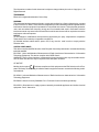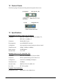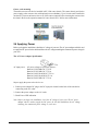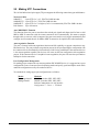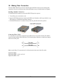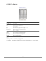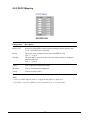
1
KGC-310 / KGC-310M
Web Smart Gigabit Ethernet Media Converter
Installation Guide
DOC.060404
-1-
(C) 2005 KTI Networks Inc. All rights reserved. No part of this documentation may be reproduced in
any form or by any means or used to make any directive work (such as translation or transformation)
without permission from KTI Networks Inc.
KTI Networks Inc. reserves the right to revise this documentation and to make changes in content
from time to time without obligation on the part of KTI Networks Inc. to provide notification of such
revision or change.
For more information, contact:
United States
International
KTI Networks Inc.
P.O. BOX 631008
Houston, Texas 77263-1008
Phone:
Fax:
E-mail:
URL:
713-2663891
713-2663893
[email protected]
http://www.ktinet.com/
Fax:
E-mail:
URL:
886-2-26983873
[email protected]
http://www.ktinet.com.tw/
-2-
The information contained in this document is subject to change without prior notice. Copyright (C). All
Rights Reserved.
TRADEMARKS
Ethernet is a registered trademark of Xerox Corp.
WARNING:
This equipment has been tested and found to comply with the limits for a Class A digital device, pursuant
to Part 15 of the FCC Rules. These limits are designed to provide reasonable protection against harmful
interference when the equipment is operated in a commercial environment. This equipment generates,
uses, and can radiate radio frequency energy and if not installed and used in accordance with the
instruction manual may cause harmful interference in which case the user will be required to correct the
interference at his own expense.
NOTICE:
(1) The changes or modifications not expressively approved by the party responsible for compliance
could void the user's authority to operate the equipment.
(2) Shielded interface cables and AC power cord, if any, must be used in order to comply with the
emission limits.
CISPR A COMPLIANCE:
This device complies with EMC directive of the European Community and meets or exceeds the following
technical standard.
EN 55022 - Limits and Methods of Measurement of Radio Interference Characteristics of Information
Technology Equipment. This device complies with CISPR Class A.
WARNING: This is a Class A product. In a domestic environment this product may cause radio interference in which case the user may be required to take adequate measures.
CE NOTICE
Marking by the symbol
indicates compliance of this equipment to the EMC directive of the Euro-
pean Community. Such marking is indicative that this equipment meets or exceeds the following technical standards:
EN 55022: Limits and Methods of Measurement of Radio Interference characteristics of Information
Technology Equipment.
EN 50082/1:Generic Immunity Standard -Part 1: Domestic Commercial and Light Industry.
EN 60555-2: Disturbances in supply systems caused by household appliances and similar electrical
equipment - Part 2: Harmonics.
-3-
Table of Contents
1. Introduction .................................................................................................. 6
1.1 Features ................................................................................................................... 7
1.2 Product Panels ......................................................................................................... 8
1.3 Specifications ........................................................................................................... 8
2. Installation .................................................................................................. 11
2.1 Unpacking ............................................................................................................... 11
2.2 Safety Cautions ...................................................................................................... 11
2.3 Mounting the Media Converter ................................................................................. 12
2.4 Applying Power ........................................................................................................ 13
2.5 Making UTP Connections ....................................................................................... 14
2.6 Making Fiber Connection ........................................................................................ 15
2.7 Loopback Test Push Button ..................................................................................... 16
2.8 Configuration DIP SW ............................................................................................. 17
2.9 LED Indication ......................................................................................................... 18
2.10 Configuring IP Address and Password for the Device ........................................... 19
3. Functions .................................................................................................... 20
3.1 Abbreviation ............................................................................................................. 20
3.2 Converter Function .................................................................................................. 20
3.3 Link Fault Pass Through Function ........................................................................... 21
3.4 Remote TP Status Monitoring Function................................................................... 22
3.5 802.1Q Control Function ......................................................................................... 23
3.6 QoS Function .......................................................................................................... 25
3.6.1 Packet Priority Classification ................................................................................ 26
3.6.2 Priority Class Queues .......................................................................................... 26
3.6.3 Egress Service Policy .......................................................................................... 26
3.7 SNMP Trap Function ................................................................................................ 27
4. Web Management ....................................................................................... 28
4.1 Start Browser Software and Making Connection ..................................................... 28
4.2 Login to the Device Unit ........................................................................................... 28
4.3 Main Management Menu .......................................................................................... 29
4.4 System .................................................................................................................... 30
4.4.1 Management VLAN ............................................................................................... 32
4.5 Ports ........................................................................................................................ 33
4.5.1 802.1Q Filtering .................................................................................................... 36
4.5.2 802.1p Mapping .................................................................................................... 37
4.5.3 DSCP Mapping ..................................................................................................... 38
4.6 Statistics.................................................................................................................. 39
4.7 Loopback Test ......................................................................................................... 40
-4-
4.8 Reboot System ....................................................................................................... 40
4.9 Restore Default ....................................................................................................... 40
4.10 Update Firmware ................................................................................................... 41
4.11 Logout .................................................................................................................... 41
Appendix A. Factory Default Settings ........................................................... 42
Appendix B. Models & Optical Specifications .............................................. 44
-5-
1. Introduction
The KGC-310 is Gigabit Ethernet media converter series which provide the following features:
Data Conversion between different Media types and Speed
The media converter supports the following conversions:
1000Mbps (1000BASE-T) copper to/from 1000Mbps (1000BASE-X) fiber
100Mbps (1000BASE-TX) copper to/from 1000Mbps (1000BASE-X) fiber
10Mbps (10BASE-T) copper to/from 1000Mbps (1000BASE-X) fiber
Mini-GBIC (SFP) Fiber Connectivity
The mini-GBIC (SFP) port can be installed with different optional SFP optical fiber transceiver to
support multimode or single mode fiber for short reach up to long reach distance.
Loopback Test Support
The media converter provides loopback test function which can verify the fiber link with its link partner
by sending test packets to the link partner and verifying the echo packets sent back. This feature is
helpful in checking connection quality of fiber link during installation.
Link Fault Pass-Through
This feature can force the link to shut down as soon as it notices that the other link has failed. It allows
a link partner on one cable segment can notice a link fault occurred on the other segment and give
application a chance to react.
Remote TP Port Status Monitoring
When two devices are connected with each other via fiber link. The device can monitor and display the
twisted-pair port status of the remote fiber link partner. The status display can be on the local LED
indicators or web management interface.
802.1Q Control
With software configuration support, the device is enhanced with more 802.1Q control features for
VLAN applications rather than just a typical media converter function. The optional features include:
Filtering all untagged packets
Filtering all tagged packets
Filtering tagged packets with certain VID
Packet Tag removal (Untagging)
Packet Tag insertion (Tagging)
-6-
Quality of Service
For conversion between two different speeds, the device is featured with powerful Quality of Service
(QoS) function which can classify the priority for received network frames based on the ingress port
and frame contents. Furthermore, many service priority policies can be configured for egress operation.
Web Management
The device is embedded with an Http server which provides management functions for advanced
network functions including Port Control, Quality of Service, and Virtual LAN functions. The management can be performed via Web browser based interface over TCP/IP network.
1.1 Features
Basic functions
Provides tri-speed 10/100/1000Mbps copper to 1000Mbps fiber conversion
Provides mini-GBIC SFP design for the fiber port to accommodate any type of SFP fiber transceiver
when needed.
Support full wire speed Gigabit copper to Gigabit fiber conversion
The copper port supports auto-negotiation and auto-MDI/MDI-X detection
Copper port auto-negotiation mode, speed and duplex configuration by DIP switch settings
Link Fault Pass Through function allows link fault status passes through between copper link and
fiber link transparently.
Far End Fault function on fiber port
Supports 802.3x flow control for full-duplex and backpressure for half-duplex
Supports loopback test between two devices over fiber link
Supports remote twisted-pair status monitoring
Diversified mounting support : desktop, wall, center rack, and optional Din-Rail support
Center chassis installation : support installation in a center chassis rack with benefits of central
software management and redundant power backup.
Support wide range of fiber options : multimode fiber, single mode fiber (short reach up to long
reach), Bi-directional single fiber, and CWDM
Management functions
Port configuration control and status monitoring
Supports Jumbo frame conversion
Packet filtering
802.1Q Control between two ports
Quality of Service (QoS) control for packet traffic
Supports loopback test
Supports remote twisted-pair status monitoring
In-band embedded firmware upgrade function
Web-based browsing interface
-7-
1.2 Product Panels
The following figure illustrates the front panel and rear panel of the device:
1.3 Specifications
10/100/1000 Twisted-pair Copper Port (TP, RJ-45)
Compliance
IEEE 802.3 10Base-T, IEEE 802.3u 100Base-TX,
IEEE 802.3u 1000Base-T
Connectors
Shielded RJ-45 jacks
Pin assignments
Auto MDI/MDI-X detection
Configuration
Auto-negotiation, manual settings or software control
Transmission rate
10Mbps, 100Mbps, 1000Mbps
Duplex support
Full/Half duplex
Network cable
Cat.5 UTP
1000Mbps Fiber Port (FX, Mini-GBIC SFP)
Compliance
IEEE 802.3z 1000Base-SX/LX (mini-GBIC)
Connectors
SFP for optional SFP type fiber transceivers
Configuration
Auto/Forced, 1000Mbps, Full duplex
Transmission rate
1000Mbps
Network cables
MMF 50/125 60/125, SMF 9/125
Eye safety
IEC 825 compliant
Loopback Test Push Button
LOOPBACK TEST
Push button to start loopback test
-8-
LED Indicators
PWR
Power status
LTP
Local or remote TP indication on TP LEDs
LBT
Loopback test in-progress LED
LBR
Loopback test result LED
FXLNK
Fiber port link and activity status
TP1G
Twisted-pair copper port 1000Mbps and link status
TP100
Twisted-pair copper port 100Mbps and link status
TP10
Twisted-pair copper port 10Mbps and link status
TPFDX
Twisted-pair copper port duplex status
Configuration DIP Switches
SW1-SW3
Twisted-pair copper port configuration
SW4
Flow control setting
SW5
Remote Twisted-pair copper port monitoring
SW6
Link fault pass through function setting
Center Interface
Interface
For center chassis mounting
Connector
FutureBus
Basic Functions
MAC Addresses
Support up to 8K
Forwarding technology
Store and forward
Maximum packet length Jumbo frame support up to 8000 bytes
Flow control
IEEE 802.3x pause frame base for full duplex operation
Back pressure for half duplex operation
DC Power Input
Interfaces
DC Jack ( -D 6.3mm / + D 2.0mm)
Operating Input Voltages +5 ~ +12VDC(+/-5%)
Power consumption
2.5W max. @7.5V
Mechanical
Dimension (base)
108 x 72.5 x 23 mm
Housing
Enclosed metal with no fan
Mounting
Desktop mounting, wall mounting, optional Rin-rail mounting
-9-
Environmental
Operating Temperature Typical -5oC ~ 55oC
Storage Temperature
-20oC ~ 85oC
Relative Humidity
10% ~ 90%
Electrical Approvals
FCC
Part 15 rule Class A
CE
EMC, CISPR22 Class A
Software Management Functions
Interfaces
Web browser
Management objects
System configuration - IP settings, Name, Password
Port configuration control and status
802.1Q control settings
QoS settings
Reboot, restore factory default, update firmware
Models
Special Features
Unmanaged model
Managed model
Configuration DIP SW
Yes
Yes
Link fault pass through
Yes
Yes
Loopback test support
Yes
Yes
Remote TP monitorng
Yes
Yes
Web management
No
Yes
Jumbo frame support
No
Yes
802.1Q Control
No
Yes
QoS Control
No
Yes
-10-
2. Installation
2.1 Unpacking
The product package contains:
• The media converter unit
• One product CD-ROM
2.2 Safety Cautions
To reduce the risk of bodily injury, electrical shock, fire, and damage to the product, observe the following precautions.
• Do not service any product except as explained in your system documentation.
• Opening or removing covers may expose you to electrical shock.
• Only a trained service technician should service components inside these compartments.
• If any of the following conditions occur, unplug the product from the electrical outlet and replace
the part or contact your trained service provider:
- The power cable, extension cable, or plug is damaged.
- An object has fallen into the product.
- The product has been exposed to water.
- The product has been dropped or damaged.
- The product does not operate correctly when you follow the operating instructions.
• Do not push any objects into the openings of your system. Doing so can cause fire or electric
shock by shorting out interior components.
• Operate the product only from the type of external power source indicated on the electrical
ratings label. If you are not sure of the type of power source required, consult your service
provider or local power company.
-11-
2.3 Mounting the Media Converter
The media converter can be mounted on a desktop or shelf or a wall. Make sure that there is proper
heat dissipation from and adequate ventilation around the device. Do not place heavy objects on the
device.
Desktop mounting
Wall mounting
The device has one mounting wall on the bottom side to support wall mounting.
Din-Rail mounting
For a Din-Rail chassis, the device can support mounting on a Din-Rail. An optional Din-Rail bracket,
KC-3DR can be purchased separately. The following figure shows an example after bracket installation:
-12-
Center rack mounting
The media converter can also be installed in KC-1300 center chassis. The center chassis provides the
power supply to the converter also with optional power redundancy. Up to 16 units can be installed in
one chassis. Unscrew and remove the cover of the center connector before inserting the converter into
the chassis. Refer to the operation manual of center chassis KC-1300 for more information.
2.4 Applying Power
Before you begin the installation, check the AC voltage of your area. The AC power adapter which is used
to supply the DC power for the unit should have the AC voltage matching the commercial power voltage in
your area.
The AC Power Adapter Specifications
AC input power:
AC power voltage of your area, options Rated AC120V/60Hz DC7.5V 1A
Rated AC230V/50Hz DC7.5V 1A
Rated AC100V/50-60Hz DC7.5V 1A
Rated AC100V/50-60Hz DC5V 1A
Rated AC240V/50Hz DC7.5V 1A
Steps to apply the power to the device are:
1. Connect power adapter DC plug to the DC input jack located on the back of the unit before
connecting to the AC outlet.
2. Connect the power adapter to the AC outlet.
3. Check Power LED indication.
Note: Before you begin the installation, check the AC voltage of your area. The AC power
adapter which is used to supply the DC power for the unit should have the AC voltage
matching the commercial power voltage in your area.
-13-
2.5 Making UTP Connections
The 10/100/1000 twisted-pair copper (TP) port supports the following connection types and distances:
Network Cables
10BASE-T:
2-pair UTP Cat. 3,4,5 , EIA/TIA-568B 100-ohm
100BASE-TX: 2-pair UTP Cat. 5, EIA/TIA-568B 100-ohm
1000BASE-T: 4-pair UTP Cat. 5 or higher (Cat.5e is recommended), EIA/TIA-568B 100-ohm
Link distance: Up to 100 meters
Auto MDI/MDI-X Function
This function allows the port to auto-detect the twisted-pair signals and adapts itself to form a valid
MDI to MDI-X connection with the remote connected device automatically. No matter a straight
through cable or crossover cable is connected, the ports can sense the receiving pair automatically and
configure itself to match the rule for MDI to MDI-X connection. It simplifies the cable installation.
Auto-negotiation Function
The port is featured with auto-negotiation function and full capability to support connection to any
Ethernet devices. The port performs a negotiation process for the speed and duplex configuration with
the connected device automatically when each time a link is being established. If the connected device
is also auto-negotiation capable, both devices will come out the best configuration after negotiation
process. If the connected device is incapable in auto-negotiation, the port will sense the speed and use
half duplex for the connection.
Port Configuration Management
For making proper connection to an auto-negotiation INCAPABLE device, it is suggested to set port
configuration to one of non-auto (forced) operating modes and specify speed and duplex mode which
match the configuration used by the connected device.
Two methods for setting copper port configuration are as follows:
Model
Unmanaged model
Managed model
Methods
DIP SW (switches) SW1, SW2, SW3
DIP SW (switches) SW1, SW2, SW3
Software management via web interface
Configuration -> Ports -> TP Mode
-14-
2.6 Making Fiber Connection
The mini-GBIC SFP (FX) port must be installed with an SFP fiber transceiver for making fiber
connection. Your device unit may come with an SFP transceiver pre-installed when it is shipped.
Installing SFP Fiber Transceiver
To install an SFP fiber transceiver into mini-GBIC SFP port, the steps are:
1. Turn off the power to the device unit.
2. Insert the SFP fiber transceiver into the mini-GBIC port. Normally, a bail is provided for every
SFP transceiver. Hold the bail and make insertion.
3. Until the SFP transceiver is seated securely in the slot, place the bail in lock position.
Connecting Fiber Cables
LC connectors are commonly equipped on most SFP transceiver modules. Identify TX and RX
connector before making cable connection. The following figure illustrates a connection example
between two fiber ports:
Make sure the Rx-to-Tx connection rule is followed on the both ends of the fiber cable.
Network Cables
Multimode (MMF) - 50/125, 62.5/125
Single mode (SMF) - 9/125
-15-
2.7 Loopback Test Push Button
The push button is used to perform loopback test between two media converters connected with fiber
cable as shown below:
It allows installer to perform diagnostic to the fiber link during installation and check the test result
displayed on the LED indicators.
The button may also be used to restore the software configuration settings to factory default values.
The operations are:
Operations
Functions
Press the button and release in normal operation
Press the button about 5 seconds when power up
Perform loopback test over fiber cable
Restore factory default settings
-16-
2.8 Configuration DIP SW
The configuration DIP SW (switches) are used for setting operation configuration manually.
The functions of each DIP SW states are:
SW1 SW2 SW3 SW4 SW5 SW6
Function
OFF
OFF
OFF
------
------
------
Ignore DIP SW6 SW5 SW4 settings
(Use software configuration for managed model)
ON
OFF
OFF
------
------
------
Set TP Port in non-auto, 10Mbps, Full duplex mode
OFF
ON
OFF
------
------
------
Set TP Port in non-auto, 10Mbps, Half duplex mode
ON
ON
OFF
------
------
------
Set TP Port in non-auto, 100Mbps, Full duplex mode
OFF
OFF
ON
------
------
------
Set TP Port in non-auto, 100Mbps, Half duplex mode
ON
OFF
ON
------
------
------
Set TP Port in auto, 1000Mbps, Full duplex mode
OFF
ON
ON
------
------
------
Disable TP Port function
ON
ON
ON
------
------
------
Set TP Port in auto, 10/100/1000Mbps, Half/Full duplex
------
------
------
OFF
------
------
Enable flow control
------
------
------
ON
------
------
Disable flow control
------
------
------
------
OFF
------
Disable remote TP status auto-report function
------
------
------
------
ON
------
Enable remote TP status auto-report on TP LEDs
------
------
------
------
------
OFF
Disable Link Fault Pass Through function
------
------
------
------
------
ON
Enable Link Fault Pass Through function
-17-
2.9 LED Indication
LED
Function
State
Interpretation
PWR
Power status
ON
OFF
The power is supplied to the unit.
The power is not supplied to the unit.
LTP
Local TP status
ON
OFF
Blink
Local TP port status displayed on TPxxx LEDs
Remote TP port status displayed on TPxxx LEDs
Fail to display remote TP port status
Remark: 1. LTP is always ON if remote TP status auto-report function is disabled.
2. When remote TP status auto-report function is enabled, LTP is ON and
OFF for ten seconds respectively.
LBT
Loopback Test
Blink
ON
OFF
Loopback Test in operation
Loopback Test Result is displayed on LBR LED.
Loopback Test stops
Remark: 1. LBT blinks to indicate loopback test in operation.
2. LBT is ON for 10 seconds to indicate a test result is displayed on LBR.
LBR
Loop Back Test Result
ON
Blink
Loopback Test OK
Loopback Test failed
Remark: 1. LBR display is valid only when LBT is ON.
2. LBR is displayed for 10 seconds to indicate a loopback test result.
FXLNK FX port link status
ON
Blink
OFF
A 1000M link is established on FX port. (No traffic)
Port link is up and there is traffic.
FX port link is down.
TP1G
TP 1000M link status
ON
OFF
A 1000M link is established on TP port.
TP port link is down.
TP100
TP 100M link status
ON
OFF
A 100M link is established on TP port.
TP port link is down.
TP10
TP 10M link status
ON
OFF
A 10M link is established on TP port.
TP port link is down.
ON
OFF
Full duplex on TP port
Half duplex on TP port
TPFDX TP duplex status
-18-
2.10 Configuring IP Address and Password for the Device
For managed model, the device unit is shipped with the following factory default settings for software
management :
Default IP address of the device : 192.168.0.2 / 255.255.255.0
The IP Address is an identification of the device unit in a TCP/IP network. Each unit should be designated a new and unique IP address in the network. Refer to Web management interface for System
Configuration.
The managed device is shipped with factory default password 123 for software management. The
password is used for authentication in accessing to the device via web-based interface. For security
reason, it is recommended to change the default settings for the device unit before deploying it to your
network. Refer to Web management interface for System Configuration.
-19-
3. Functions
To help a better understanding about the software management interfaces, this chapter describes some
advanced functions provided by the media converter.
3.1 Abbreviation
TP Port : The twisted-pair copper port of the media converter device.
FX Port : The optical fiber port of the media converter device.
Ingress Port : Ingress port is the input port on which a packet is received.
Egress Port : Egress port is the output port from which a packet is sent out.
IEEE 802.1Q Packets : A packet which is embedded with a VLAN Tag field
VLAN Tag : In IEEE 802.1Q packet format, 4-byte tag field is inserted in the original Ethernet frame
between the Source Address and Type/Length fields. The tag is composed of :
#of bits
Frame field
16
TPID
3
User priority
1
CFI
12
VID
TPID : 16-bit field is set to 0x8100 to identify a frame as an IEEE 802.1Q tagged packet
User Priority : 3-bit field refer to the 802.1p priority
CFI : The Canonical Format Indicator for the MAC address is a 1 bit field.
VID : VLAN identifier, 12-bit field identifies the VLAN to which the frame belongs to.
Untagged packet : A standard Ethernet frame with no VLAN Tag field
Priority-tagged packet : An IEEE 802.1Q packet which VID field value is zero (VID=0)
In the device, this packet is also treated as untagged packet.
VLAN-Tagged packet : An IEEE 802.1Q packet which VID field value is not zero (VID<>0)
PVID (Port VID)
PVID is the default VID of an ingress port. It is used in 802.1Q filtering for untagged packets. It is also
often used as [Default Tag - VID] for egress tagging operation.
DSCP : Differentiated Service Code Point, 6-bit value field in an IP packet
3.2 Converter Function
The device supports the following data conversions between fiber cable and twisted-pair Cat.5 (copper) cable:
The data rate on twisted-pair segment depends on the link speed finally established with the link partner.
-20-
3.3 Link Fault Pass Through Function
Description
When the Link Fault Pass Through (LFPT) function is enabled and the media converter detects a link
fault on one port segment, it will force the other port segment link down. It looks like that a link fault is
passed from one port to the other.
The following example illustrates a link fault occurs on the fiber cable (any one cable in a duplex fiber
connection). The link fault is forwarded to both Gigabit link partners finally by LFPT operation of two
media converters.
Both Gigabit devices will also detect a link fault on each Cat.5 connection, although the real fault occurs
on the fiber connection exactly.
The following example illustrates a real link fault occurs on one Cat.5 and the link fault is passed to the
other Cat.5 over two converters and the fiber cable by LFPT operation. Finally, the other link partner
also detects a link fault.
Advantage
The function allows two remote link partners of the media converters detect the link fault finally no
matter where the exact fault occurs. It allows the upper application takes necessary action in case a
real link fault occurs in any cable segment.
Methods to enable the function
The LFPT function can be enabled by:
Hardware setting:
Software setting:
DIP SW6 is set to ON position
Web management ->
Configuration -> System -> [Link fault pass through]
-21-
3.4 Remote TP Status Monitoring Function
Description
The local media converter can monitor the TP port link status of its remote link partner connected on
the fiber cable. The status are displayed on the local LED indicators as follows:
Methods to enable the function
Hardware setting:
DIP SW5 is set to ON position
Software setting:
Web management ->
Configuration -> System -> [Remote TP auto report]
Remote TP Status Display
1. The status are displayed on local LEDs - TP1G, TP100, TP10, TPFDX when LTP is OFF.
LED
LTP
TP1G
State
OFF
ON
OFF
TP100 ON
OFF
TP10
ON
OFF
TPFDX ON
OFF
Status
Remote TP status is valid on the following LEDs
Remote TP link in 1000Mbps
Remote TP link down
Remote TP link in 100Mbps
Remote TP link down
Remote TP link in 10Mbps
Remote TP link down
Remote TP link in full duplex
Remote TP link in half duplex
2. Web management -> Monitoring -> Statistics -> Remote TP [Link]
-22-
3.5 802.1Q Control Function
802.1Q Control function allows to perform 802.1Q VLAN related operation to the packets passing
through the media converter according packet contents as follows:
[Ingress Drop] setting
The setting is the first filtering mechanism to filter all incoming untagged packets or to filter all incoming
VLAN-tagged packets. The options are:
Disable -
Disable port ingress drop function
Untag Only -
All incoming untagged packets and priority-tagged packets are dropped.
Only VLAN-tagged packets are admitted.
Tag Only -
All incoming VLAN-tagged packets are dropped.
Only untagged packets and priority-tagged packets are admitted.
[Ingress Keep Tag], [Egress Insert Tag] settings
The settings are used together for packet egress tagging or untagging as table listed below:
Ingress Keep Tag Egress Insert Tag Packet Modification
Enable
Disable
All packets are with no modification.
Disable
Disable
All packets are untagged in egress.
Disable
Enable
All packets are tagged in egress.
Enable
Enable
Settings not recommended (possible double-tagging)
[Ingress Keep Tag] options:
Enable The VLAN tag in the received VLAN-tagged packet will be kept as it is and is
not stripped in whole conversion operation.
Disable -
The VLAN tag data in the received VLAN-tagged packet is stripped (removed).
[Egress Insert Tag] options:
Enable Insert a tag into the packet in egress. The tag inserted is based on the rule below:
Incoming Packet Type
Untagged
Priority-tagged
VLAN-tagged
Disable -
Tag inserted
Ingress port Default Tag
Ingress port Default Tag
Received packet own tag
No tagging is performed.
-23-
[Default Tag -VID], [Default Tag - CFI], [Default Tag - Priority] settings
These settings compose one ingress port Default Tag. This tag is used when a tag insertion is required
for untagged packets.
802.1Q Filtering
802.1Q VID Filtering function allows to admit or reject certain VID tagged packets. Up to 16 allowed
(positive list) or rejected (negative list) VIDs can be configured. This function allows to limit certain
packets to pass from one link segment to another one.
[VID Table] options
Disable 802.1Q VID filtering is disabled.
Allowed VID -
Only the VLAN-tagged packets with VIDs in VID table are admitted.
Rejected VID -
The VLAN-tagged packets with VIDs in VID table are rejected and dropped.
For untagged and priority-tagged packets, the ingress [Default Tag - VID], also called PVID is used for
VID filtering. If it is in Allowed VID table, the untagged packet is allowed to pass; otherwise, dropped.
If it is in Rejected VID table, the untagged packet is dropped.
-24-
3.6 QoS Function
The device provides a powerful Quality of Service (QoS) function to guide the packet forwarding in
four priority classes. The versatile classification methods can meet most of the application needs.
The function is useful for guiding the incoming traffic on high data rate port into low data rate port in
priority. The following figure illustrates the QoS operation flow when a packet received on the ingress
port until it is transmitted out from the egress port:
Since the media converter can support full wire speed conversion for 1000Mbps to 1000Mbps, QoS
function is not essential for such application. It is suggested to disable the QoS function for 1000Mbps
to 1000Mbps conversion.
-25-
3.6.1 Packet Priority Classification
Each received packet is examined and classified into one of four priority classes, Class 3, Class 2,
Class 1 and Class 0 upon reception. The device provides the following classification methods:
802.1p classification : use User Priority tag value in the received IEEE 802.1Q packet to map to one
priority class
DSCP classification : use DSCP value in the received IP packet to map to one priority class
Port-based classification : used when 802.1p and DSCP are disabled or fail to be applied
They all can be configured to be activated or not. More than one classification methods can be enabled
at the same time. However, 802.1p classification is superior than DSCP classification.
802.1p mapping tables : Each port has its own mapping table for 802.1p classification.
DSCP mapping table : Two ports share one DSCP mapping table for DSCP classification.
Default port priority : A port default priority class is used when port-based classification is applied
All configuration settings are in per port basis except that DSCP mapping table is global to all ports. A
received packet is classified into one of four priority class before it is forwarded to an egress port.
3.6.2 Priority Class Queues
Each port in the device is equipped with four priority class egress queues to store the packets for
transmission. A packet is stored into the class queue which is associated to the classified priority class.
For example, a packet is stored into Class 3 egress queue if it is classified as priority Class 3.
3.6.3 Egress Service Policy
Each port can be configured with an egress service policy to determine the transmission priority among
four class queues. By default, higher class number has higher priority than the lower class numbers.
Four policies are provided for selection as follows:
•
•
•
•
Strict priority : Packets in high priority class queue are sent first until the queue is empty
Weighted ratio priority Class 3:2:1:0 = 4:3:2:1 : four queues are served in 4:3:2:1 ratio
Weighted ratio priority Class 3:2:1:0 = 5:3:1:1 : four queues are served in 5:3:1:1 ratio
Weighted ratio priority Class 3:2:1:0 = 1:1:1:1 : four queues are served equally
Strict priority policy lets high priority class queue is served first until it is empty. Lower priority queue
may not get any service (or egress bandwidth) when higher priority traffic is heavy for long time. Three
weighted ratio policies are provided to resolve such problem. Four class queues are served in weighted
round robin basis. Every priority class can get a guaranteed ratio for the egress bandwidth.
-26-
3.7 SNMP Trap Function
SNMP trap function allows the device to send trap message to an SNMP trap host over SNMP protocol
when the associated trap event occurs.
SNMP Trap settings
The settings are used to configure a trap host who can receive the SNMP trap message issued from a
media converter device unit.
[SNNP Trap]
Enable / disable SNMP trap function
[Community Name]
The community string bound in a trap message
[Trap IP Address]
The IP address of the target SNMP trap host who is allowed to receive the
traps.
SNMP Trap events
The following events are defined for generating a trap message when the event occurs on the unit.
The device boot up.
TP copper port link down
TP copper port link up (link recovery).
FX fiber port link down
FX fiber port link up (link recovery).
The following example illustrates an event of FX port link down occurs and is detected by the device.
Then, it generates a trap message to the SNMP trap host PC.
-27-
4. Web Management
The media converter features an http server which can serve the management requests coming from
any web browser software over TCP/IP network.
Web Browser
Compatible web browser software with JAVA script support
Microsoft Internet Explorer 4.0 or later
Netscape Communicator 4.x or later
Set IP Address for the System Unit
Before the device unit can be managed from a web browser software, make sure a unique IP address
is configured for the unit.
4.1 Start Browser Software and Making Connection
Start your browser software and enter the IP address of the unit to which you want to connect. The IP
address is used as URL for the browser software to search the device.
URL : http://xxx.xxx.xxx.xxx/
Factory default IP address : 192.168.0.2
4.2 Login to the Device Unit
When browser software connects to the device unit successfully, a Login screen is provided for you to
login to the device as follows:
The device will accept only one successful management connection at the same time. The other connection attempts will be prompted with a warning message.
A new connection will be accepted when the current user logout successfully or auto logout by the
device due to no access for time out of 3 minutes. System Configuration is displayed after a successful login.
-28-
4.3 Main Management Menu
The following information describes the basic functions of the main menu.
Configuration
System
Device information, system and IP related settings
Ports
Port link status, operation mode configuration and other per port settings
Monitoring
Statistics
List statistics for the local ports and remote TP port link status
Maintenance
Loopback Test
Command to perform loopback test on fiber link
Reboot System
Command to reboot the device unit
Restore Default
Command to restore the device unit with factory default settings
Update Firmware
Command to update the device firmware
Logout
Command to logout from current web management
-29-
4.4 System
Configuration
Description
MAC Address
The MAC address factory configured for the unit
It can not be changed in any cases.
S/W Version
The firmware version currently running
H/W Version
The hardware version currently operating
Management VLAN
- VID
- CFI
- User priority
Set management VLAN information (See next section)
VLAN ID configured for web management to the device
CFI value for web reply packets from the device
Priority value for web reply packets from the device
IP Address
Set IP address for the device web management
Subnet Mask
Set Subnet mask for IP address for the web management
Gateway
Set Default gateway IP address for the web management
Name
Set the system name for this device unit
Password
Set new password
-30-
SNMP Trap
SNMP trap function configuration
Disable - the device is disable to send SNMP trap messages.
Enable - the device is enable to send SNMP trap messages.
Community Name
Set community string to be bound with trap packets
Trap IP Address
Set IP address of the SNMP trap host
802.1Q Control
802.1Q Control function main configuration
Disable - all packets are allowed to pass with no 802.1Q control.
Enable - 802.1Q control mechanism is activated for the conversion.
QoS Control
Enable / disable QoS Control function main configuration
Disable - Packet priority classification function is disabled.
Enable - Packet priority classification function is enabled.
Jumbo Mode
Enable / disable Jumbo mode to support jumbo packets
Disable - support maximum packet size up to 1526 bytes
Enable - support maximum packet size up to 8000 bytes
Link fault pass through
Enable / disable link fault pass through function
Remote TP auto report
Enable / disable remote TP port link status function
[Apply]
Click to apply the configuration change
[Refresh]
Click to refresh current configuration
Note:
It is suggested to give each device unit a system name as an alternative unique
identification beside IP address.
-31-
4.4.1 Management VLAN
Management VLAN settings allow administrator to access the device and perform the web management over a dedicated VLAN only.
The following rules are applied with the Management VLAN:
1. If the 802.1Q Control function is disabled, Management VLAN settings are ignored and no
VLAN limitation is applied in accessing the web management interface. The http server only
accepts untagged management packets and replies untagged packets to the management host.
2. If [Management VLAN - VID] settings is zero, no VLAN limitation is applied in accessing the
web management interface. The http server only accepts untagged management packets and
replies untagged packets to the management host.
3. If [Management VLAN - VID] settings is not zero, The http server only accepts tagged management packets matched [Management VLAN -VID] and replies tagged packets with tag composed of [Management VLAN] VID, CFI and User Priority settings to the management host.
Summary of the rules:
802.1Q Control
Disabled
Management VLAN VID
Ignore
Enabled
VID=0
Enabled
VID<>0
( 1 ~ 4095)
Embedded Http (Web) Server operation
Accept untagged web packets
Reply untagged packets
Accept untagged web packets
Reply untagged packets
Accept matched tagged web packets only
Reply tagged packets with the configured tag
Notes:
1. No matter how management VLAN is configured, login password authentication is still
required.
2. Default [Management VLAN - VID] is equal to zero. It is allowed to access the device from
any untagged PC web browser.
3. Most of the PCs are tag-incapable for LAN access. Be sure the rules are followed before
setting [Management VLAN - VID] not equal to zero.
-32-
4.5 Ports
Ports Configuration has three major parts as follows:
Port Configuration
Port link status, port operating mode, port flow control
802.1Q Control
802.1Q Control per port settings
QoS Control
QoS Control per port settings
-33-
Port Configuration
Function
Port
TP - Twisted-Pair copper port
FX - Fiber port
Link
Port link status
Speed and duplex status with green background - port is link on
Down with red background - port is link down
Mode
Select port operating mode
Disabled - disable the port operation
TP Mode
Disable
Auto
10 Half
10 Full
100 Half
100 Full
1000 Full
Auto-negotiation
Speed capability
Disable port operation
Enable
10, 100, 1000M
Disable
10M
Disable
10M
Disable
100M
Disable
100M
Enable
1000M
FX Mode
Disable
1000 Full
Force 1000 Full
Duplex capability
Full, Half
Half
Full
Half
Full
Full
Auto-negotiation
Speed capability Duplex capability
Disable port operation
Enable
1000M
Full
Disable
1000M
Full
Flow Control
Set port flow control function
V - set to enable 802.3x pause flow control for ingress and egress
802.1Q Control
Function
Ingress Drop
Disable - disable port ingress drop and admit all packet types
Untag Only - Drop both untagged and priority-tagged packets
Tag Only - Drop VLAN-tagged packets (VID<>0)
Ingress Keep Tag
Tag is removed from the received packet if it exists.
Enable - set to activate tag removal for VLAN-tagged packets
Disable - set to disable tag removal function
Egress Insert Tag
Tag is inserted into the outgoing packet in egress operation.
Enable - set to activate tagging
Disable - set to disable tagging function
Default Tag - VID
Port VID, VID for Ingress Default Tag
1 ~ 4095 - decimal 12-bit VID value
Default Tag - CFI
CFI for Ingress Default Tag
0, 1 - 1-bit CFI value
Default Tag -Priority
User priority for Ingress Default Tag
0 ~ 7 - decimal 3-bit value
[802.1Q Filtering]
Click to set VID filtering table
-34-
QoS Control
Description
QoS 802.1p
802.1p priority classification
Enable - set to enable this classification to the port for priority-tagged and
VLAN-tagged packets
Disable - 802.1p classification is not applied to the port
QoS DSCP
DSCP classification
Enable - set to enable DSCP classification to the port for IP packets
Disable - DSCP classification is not applied to the port.
QoS Default Priority
Default priority class, it is used when 802.1p and DSCP classifications are
disabled. It is also used as default priority class for the received packet
when both 802.1p and DSCP classification failed in classification.
Class 3 ~ Class 0 - priority class
QoS Egress Service
Service policy for egress priority among four egress class queues
Strict priority - high class queue is served first always till it is empty
Ratio 4:3:2:1 - Weighted ratio priority Class 3:2:1:0 = 4:3:2:1
Ratio 5:3:1:1 - Weighted ratio priority Class 3:2:1:0 = 5:3:1:1
Ratio 1:1:1:1 - Weighted ratio priority Class 3:2:1:0 = 1:1:1:1
[802.1p Mapping]
Click to configure 802.1p mapping tables.
[DSCP Mapping]
Click to configure DSCP mapping table.
[Apply]
Click to apply the configuration change
[Refresh]
Click to refresh current configuration
Notes:
1. 802.1p classification is superior over DSCP classification if both are enabled. That means
if a received packet is classified successfully in 802.1p classification, the classified priority
class is used directly for the packet and the result of DSCP classification is ignored.
2. Queue with higher class number has higher priority than queue with lower class number.
That means Class 3 > Class 2 > Class 1 > Class 0 by default.
3. In weighted ratio policies, a weighted fairness round robin service is guaranteed normally.
However, when excess bandwidth exists higher class queue will take advantage on bandwidth allocation.
4. It is suggested to apply QoS Control function only on 1000M to 100M conversion. Under
1000M to 1000M full wire speed conversion, the effect of QoS control function is not
obvious.
5. The function of all three [Apply] buttons are identical. Click any one to apply the change.
6. The function of all three [Refresh] buttons are identical. Click any one to refresh settings.
-35-
4.5.1 802.1Q Filtering
Configuration
Description
VID TABLE
Specify the characteristic of the VID table.
Disable - set to disable 802.1Q filtering function.
Allowed VID - the VID table specifies the allowed VIDs
rejected VID - the VID table specifies the rejected VIDs
No.
Entry of VID table - up to 16 VIDs can be configured in VID table
VID
1 ~ 4095 - decimal 12-bit VID value
[Apply]
Click to apply the configuration change.
[Refresh]
Click to refresh current configuration.
[Close]
Click to close this window.
Notes:
1. VID table is referred for filtering VLAN-tagged packets according to the VID value embedded in the packet. For untagged or priority-tagged packet, [Default Tag - VID], also
called PVID is used instead in referring VID table.
2. [Allowed VID] setting is useful when only certain VIDs are allowed to pass the device.
3. [Rejected VID] setting is useful when only certain VIDs are not allowed to pass the device.
-36-
4.5.2 802.1p Mapping
Configuration
Description
Port
TP - Twisted-Pair copper port
FX - Fiber port
tag m
3-bit User priority tag value m ( range : 0 ~ 7 )
Priority class
Mapped priority class for tag m on Port
Class 3 ~ Class 0
[Apply]
Click to apply the configuration change
[Refresh]
Click to refresh current configuration
[Close]
Click to close the window
Notes:
1. Each port has its own 802.1p mapping table.
2. The ingress port table is referred in 802.1p priority classification for a received packet.
-37-
4.5.3 DSCP Mapping
Configuration
Description
DSCP [0-63]
Seven user-defined DSCP values which are configured with a priority class
0 ~ 63 - 6-bit DSCP value in decimal
Priority
The priority class configured for the user-defined DSCP value
Class 3 ~ Class 0
All others
The other DSCP values not in the seven user-defined values are assigned a
default priority class
Class 3 ~ Class 0
[Apply]
Click to apply the configuration change
[Refresh]
Click to refresh current configuration
[Close]
Click to close the window
Notes:
1. Only one DSCP mapping table is configured and applied to both ports.
2. The table is referred in DSCP priority classification for a received packet.
-38-
4.6 Statistics
Configuration
Description
Port
TP - Twisted-Pair copper port on local unit
FX - Fiber port on local unit
Remote TP - TP port of the remote unit connected on the fiber link
Link
Port link status
Speed and duplex status with green background - port is link on
Down with red background - port is link down
Tx Bytes
Total of bytes transmitted on the port
Tx Frames
Total of packet frames transmitted on the port
Rx Bytes
Total of bytes received on the port
Rx Frames
Total of packet frames received on the port
Tx Errors
Total of error packet frames transmitted on the port
Rx Errors
Total of error packet frames received on the port
[Clear]
Click to reset all statistic counters
[Refresh]
Click to refresh all statistic counters
-39-
4.7 Loopback Test
This menu is used to start a loopback test operation with the link partner unit over the fiber link. The
message displayed during test is:
The result message displayed after a test finished is:
The test result is also displayed on LEDs - LBT and LBR.
4.8 Reboot System
This menu is used to reboot the device unit remotely with current configuration. Starting this menu will
make your current http connection lost. You must rebuild the connection to perform any management
operation to the unit.
4.9 Restore Default
This menu is used to restore all settings of the device unit with factory default values. Note that this
menu might change the current IP address of the device and make your current http connection lost.
-40-
4.10 Update Firmware
This menu is used to perform in-band firmware (software) upgrade. Enter the path and file name of
new firmware image file for uploading.
Configuration
Description
Filename
Path and filename (warp format)
[Browse]
Click to browse your computer file system for the firmware image file
[Upload]
Click to start upload
4.11 Logout
This menu is used to perform a logout from the web management. If current user does not perform any
management operation over 3 minutes, the device will execute an auto logout and abort the current
connection.
-41-
Appendix A. Factory Default Settings
Configuration DIP SW Unmanaged Model
Managed Model
SW3 SW2 SW1
ON ON ON
OFF OFF OFF
Auto,10/100/100,Full/Half
Web configuration (SW4-6 ignored)
SW4
OFF (Enable flow control)
OFF
SW5
OFF (Disable remote TP auto report)
OFF
SW6
OFF (Disable link fault pass through) OFF
System Configuration
Management VLAN - VID
0
Management VLAN - CFI
0
Management VLAN - User priority
0
IP Address
192.168.0.2
IP Subnet mask
255.255.255.0
Gateway IP
192.168.0.1
Name
Null
Password
123
SNMP Trap
Disable
Community Name
Null
Trap IP Address
0.0.0.0
802.1Q Control
Disable
QoS Control
Disable
Jumbo Mode
Disable
Link fault pass through
Disable
Remote TP auto report
Disable
Ports Configuration
Mode
Auto for TP port, 1000 Full for FX port
Flow Control
v : Enable
Ingress Drop
Disable
-42-
Ingress Keep Tag
Enable
Egress Insert Tag
Disable
Default Tag - VID (PVID)
1
Default Tag - CFI
0
Default Tag - Priority
0
QoS 802.1p
Disable
QoS DSCP
Disable
QoS Default Priority
Class 3
QoS Egress Service
Strict priority
802.1Q Filtering
VID TABLE
Disable
VID n (n=1-16)
n
802.1p Mapping
tag 0
Class 0
tag 1
Class 0
tag 2
Class 1
tag 3
Class 1
tag 4
Class 2
tag 5
Class 2
tag 6
Class 3
tag 7
Class 3
DSCP Mapping
DSCP / Priority 1 -7
Null / Class 0
All others
Class 0
-43-
Appendix B. Models & Optical Specifications
Model Definition
KGC-310
KGC-310-xxxx
KGC-310M
KGC-310M-xxxx
Model Ext.
-SX
-LX
-LX20
-LX30
-LX50
-LX70
Unmanaged model with no pre-installed SFP transceiver
Unmanaged model with pre-installed SFP transceiver
Managed model with no pre-installed SFP transceiver
Managed model with pre-installed SFP transceiver
FiberCon.
LC
LC
LC
LC
LC
LC
Reference Fiber Distance (Typ.)
Duplex MMF 500m
Duplex MMF 550m, SMF 10km
Duplex SMF 20km
Duplex SMF 30km
Duplex SMF 50km
Duplex SMF 70km
Bi-directional WDM over single SMF
-W3510
LC
Simplex SMF 10km
-W5310
LC
Simplex SMF 10km
-W3520
LC
Simplex SMF 20km
-W5320
LC
Simplex SMF 20km
-W3410
LC
Simplex SMF 10km
-W4310
LC
Simplex SMF 10km
-W3410S
SC
Simplex SMF 10km
-W4310S
SC
Simplex SMF 10km
Optical Specifications
Model Ext. Wavelength
-SX
850nm
-LX
1310nm
-LX20
1310nm
-LX30
1310nm
-LX50
1550nm
-LX70
1550nm
Bi-Direction
-W3510
-W5310
-W3520
-W5320
-W3410
-W4310
-W3410S
-W4310S
Tx Power*1
-9.5~ -4
-9.5~ -3
-7~ 0
-4~ +3
-4~ +1
0~ +5
Rx Sen.*2 Max.Rx*3
-18
-1
-20
-3
-24
-3
-23
-3
-23
-3
-23
-3
WDM over single SMF
T1310/R1550
-9~ -3
T1550/R1310
-9~ -3
T1310/R1550
-8~ -3
T1550/R1310
-8~ -3
T1310/R1550
-9~ -3
T1550/R1310
-9~ -3
T1310/R1550
-9~ -3
T1550/R1310
-9~ -3
-21
-21
-23
-23
-20
-20
-20
-20
*1 Tx Power : Transmitter power (min. ~ max., unit: dBm)
*2 Rx Sen. : Receiver sensitivity (unit :dBm)
*3 Max.Rx. : Maximal Received power (unit : dBm)
-44-
-3
-3
-3
-3
-3
-3
-3
-3