1
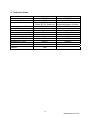
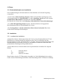
DIGITALVARIO
Kurzanleitung
Ausgabe 0.3 deutsch 29.11.2005
für Direkt-Digital-Vario
Firmware ab
Hardware
Seriennummer
00-02-02
01
ab 0003
1
Bedienung kurz-02.doc
INHALT
1. VORWORT................................................................................................. 3
2. TECHNISCHE DATEN............................................................................... 4
3. EINBAU....................................................................................................... 5
4. KURZANLEITUNG...................................................................................... 9
5. BEDIENUNGSANLEITUNG........................................................................
6. ANHANG..................................................................................................... 15
2
Bedienung kurz-02.doc
1. VORWORT
Da sich das Gerät noch in Entwicklung befindet, kann zurzeit keine
Funktionsgarantie gegeben werden. Jedoch wurde das Gerät sorgfältig
konstruiert und gebaut, sodass ein sicherer und störungsfreier Betrieb möglich ist.
Viele Funktionen sind noch nicht verfügbar oder unpassend gelöst, Ziel der
Erprobung ist es genau diese Probleme zu finden und zu lösen. Dabei ist die
Mithilfe der Testpiloten wichtig. Ich freue mich also über jede konstruktive Kritik,
egal ob positiv oder negativ. Dadurch ist es möglich das Vario weiter zu
verbessern.
Natürlich muss auch noch an dieser Bedienungsanleitung gearbeitet werden.
Sollten also Punkte unverständlich sein oder nicht erklärt worden sein, so bitte ich
um Hinweise.
Sie erreichen mich unter
[email protected]
oder unter der Telefonnummer
+49 17621203726
+49 2331 9239511
Für alle Bemühungen danke ich im Voraus
Jens Kampmann
3
Bedienung kurz-02.doc
2. Technische Daten
Stromversorgung
Betriebstemperatur
Stromaufnahme
min
10.0 V DC
-20 °C
120mA @ 12V Audio aus
130mA @ 12V Audio laut
max
16.0V DC
+70°C
variiert je nach extern
angeschlossenen Geräten
4,5A Peak
-10 m/s
- 6 m/s
- 5 m/s
-100m
40km/h
+10 m/s
+ 6 m/s
+ 5m/s
>15 000m
300km/h
Ausgangsstrom +5V
Messbereich Vario
Digital
Akustisch
Anzeigenadel
Messbereich Höhe
Messbereich Fahrt
Gewicht
TBD
4
Bedienung kurz-02.doc
3. Einbau
3.1. Sicherheitshinweise zur Installation
Eine Nichtbeachtung der Sicherheitshinweise kann Schäden an Gerät und Umgebung
verursachen.
· In das Gerät ist keine Sicherung integriert. Daher ist beim Einbau ins Flugzeug in die
Versorgungsleitung eine Feinsicherung (3A, träge) einzufügen, um Brände oder sonstige
Schäden durch Kurzschlüsse in Kabeln oder Gerät zu vermeiden.
Der Betrieb des Gerätes über eine Sicherung ist Bestandteil der Garantiebestimmungen.
· Es ist kein Überspannungsschutz integriert. Ein Überschreiten der angegebenen
Betriebsspannung führt zur Beschädigung des Gerätes.
· Das Gerätegehäuse ist mit der elektrischen Masse leitend verbunden. Bitte beim
Geräteeinbau unbedingt berücksichtigen.
3.2. Installation
3.2.1. mechanische Installation
Aufgrund der kleinen Abmessungen kann das Vario in einen Normausschnitt mit 57 mm
Durchmesser im Instrumentenbrett eingebaut werden. Zum Verschrauben mit dem
Instrumentenbrett werden 4 Schrauben M3,5 verwendet. Auf ausreichenden Platz hinter dem
Instrumentenbrett ist zu achten, da sonst ein einwandfreier Einbau der elektrischen und
pneumatischen Zuleitungen nicht gewährleistet ist.
Auf der Rückseite des Geräts befinden sich die pneumatischen Anschlüsse für folgende
Drücke:
p
p+q
p-q
:Statischer Druck
:Staudruck
:Druck der TE-Düse
Darauf achten, dass der TE-Düsendruck einwandfrei ist. Nach Möglichkeit keine anderen
Geräte an diese Druckleitung anschließen. Siehe Bemerkungen über TE-Düsen im Anhang!
5
Bedienung kurz-02.doc
3.2.2. elektrische Installation
Die Stromversorgung erfolgt über eine 8-polige Western-Buchse (RJ-45) an der Rückseite des
Gerätes.
Beim Anschluss ist vorsichtig zu verfahren, die Stecker der Kabel passen nur in einer
Position in die Buchsen am Gerät.
Es wird empfohlen, das Vario an einer eigenen Batterie zu Betreiben um eine Beeinflussung
durch andere Verbraucher, besonders Funkgeräte oder ähnliches auszuschließen.
Bei Benutzung des mitgelieferten Anschlusskabels ist die Belegung folgendermaßen:
rot
schwarz
Pluspol der Versorgungsspannung(+12V)
Minuspol der Versorgungsspannung (Masse / 0V)
Belegung der Adern der Vario - Anschlusskabel:
RJ-45 Buchse untere Reihe
_____
|1
8| Stecker (Feder unten)
|
|
| ___ |
||___||
----| |
| |
| |
RJ-45|
-----'
1
Orange- strichliert
2
Orange
3
Grün - strichliert
4
Blau
5
Blau - strichliert
6
Grün
7
Braun - strichliert
8
Braun
braun und braun- strichliert (7+8):
Pluspol der Versorgungsspannung
orange und orange- strichliert (1+2):
Minuspol der Versorgungsspannung (+12 V)
blau (4):
grün- strichliert (3):
Daten (CAN-Interface)
Daten (CAN-Interface)
Abschirmung :
kann am Minuspol der Versorgungsspannung
angeschlossen werden, um eventuelle
Störungen im Funk zu verringern
blau- strichliert (5):
STANDBY (noch nicht unterstützt)
6
Bedienung kurz-02.doc
RJ-45 Buchse obere Reihe (externe Geräte z.B. Logger oder IPAQ)
_____
|1
8| Stecker (Feder unten)
|
|
| ___ |
||___||
----| |
| |
| |
RJ-45|
-----'
1
Orange- strichliert
2
Orange
3
Grün - strichliert
4
Blau
5
Blau - strichliert
6
Grün
7
Braun - strichliert
8
Braun
braun und braun- strichliert (7+8):
Pluspol der Versorgungsspannung (+12 V)
für extern angeschlossene Geräte
grün und blau- strichliert (5 +6):
Pluspol (+5V) für extern angeschlossene
Geräte
orange und orange- strichliert (1+2):
Minuspol der Versorgungsspannungen und
der Datenleitungen(Masse)
blau (4):
grün- strichliert (3):
Abschirmung:
Dateneingang (PC-Kommunikation oder
NMEA)
Datenausgang (PC-Kommunikation oder
NMEA)
kann am Minuspol (Masse) der
Versorgungsspannung angeschlossen werden.
7
Bedienung kurz-02.doc
RJ-11 Buchse
_____
|1
6| Stecker (Feder unten)
|
|
| ___ |
||___||
----| |
| |
| |
RJ-11|
-----'
(1)
(2)
(3)
(4)
(5)
(6)
Masse (Lautsprecher Minus Anschluss)
Lautsprecher(Plus Anschluss)
Sollfahrt Umschalter
IIC Bus (SCL)
IIC Bus (SDA)
+3,3V
An die erforderliche Absicherung der Versorgungsspannung(+12V) wird nochmals
erinnert!
Der Anschluss des Kabels an die Flugzeugelektrik darf nur von versierten Fachleuten
unter Beachtung der anerkannten Regeln der Elektrotechnik vorgenommen werden. Die
Kabelbelegung ist genauestens zu beachten. Bei Nichtbeachtung kann die Elektronik des
Varios Schaden nehmen.
Die in den technischen Daten angegebenen Betriebsgrenzen sind unbedingt einzuhalten, um
Schäden am Gerät zu vermeiden.
Das Gerät ist mit einem internen Verpolungsschutz für die Versorgungsspannung ausgestattet.
Trotzdem sollte beim Anschluss auf korrekte Polung geachtet werden.
Anmerkung: Obwohl das Gerät selbst gegen Verpolung geschützt ist, kann z.B. ein
angeschlossener Logger bei Verpolung des Varios über die Schnittstelle
beschädigt werden.
8
Bedienung kurz-02.doc
4. KURZANLEITUNG
Das Vario besitzt keinen Ein/Aus – Schalter. Die Inbetriebnahme erfolgt durch
Einschalten der Bord/ Versorgungsspannung.
Das Vario hat neben der Anzeigenadel ein Display mit 4 Zeilen, auf dem verschiedene
Informationen angezeigt werden können.
Die Bedienung erfolgt über einen Drehschalter (mit zwei Ebenen und Drucktaster) an der
rechten Frontseite.
Nach Einschalten zeigt das Display Seriennummer und Softwareversion an.
Dabei fährt die Variometernadel an den oberen Anschlag(+5m/s) um die NullpunktJustierung vorzunehmen. Kurz danach schaltet das Vario in den Normalmodus und der
Variometerwert pendelt sich langsam auf 0 m/s ein.
Das Vario sollte einige Zeit vor dem Flug bereits eingeschaltet werden, damit es sich auf
Betriebstemperatur erwärmen kann.
Vor dem Start:
Vor dem Start sollte in die Menübetriebsart gewechselt werden und folgende
Einstellungen vorgenommen werden:
1/1 QNH
Einstellen des QNH auf den tagesaktuellen Wert.
Die Funktion entspricht einem mechanischen Höhemesser, der auch vor dem Start auf
die gewünschte Bezugshöhe eingestellt wird.
Wird der Wert auf den QNH gestellt, so zeigt er Höhenmesser (ALT) die Höhe über
MSL an. Ist der QNH nicht bekannt, kann der Wert so lange verstellt werden, bis der
Höhenmesser die Platzhöhe über MSL anzeigt. Natürlich kann auch mit einer anderen
Bezugshöhe geflogen werden.
4/7 OFFSET
Zeigt die Nadel des Variometers nach einer gewissen Zeit nicht auf den gleichen Wert
wie die digitale Varioanzeige im Display, so kann die Nadel in diesem Menüpunkt
nachjustiert werden, sodass beide Anzeigen analog zueinander laufen.
Man kann die Nadel vorsichtig mit der Hand bewegen ohne dabei das Gerät zu
beschädigen, jedoch ist so nur eine ungefähre Einstellung möglich. In diesem
Menüpunkt kann die Nadel dann genau auf den richtigen Wert gestellt werden.
Im Flug oder am Boden:
Alle Einstellungen können zu jeder Zeit verändert werden.
9
Bedienung kurz-02.doc
Erklärung der angezeigten Informationen:
VA
Variometerwert in m/s – totalenergiekompensiert
(bei Verwendung einer TE-Düse) Die Zeitkonstante wird durch die
Einstellung T_VAR im Menü verändert.
ALT
Totalenergie-Höhe
Zeigt die aktuelle Höhe über der eingestellten Bezugsfläche(QNH) +
Fahrtanteil. Die angezeigte Höhe weicht um den Fahrtanteil von der
barometrischen Höhe ab. Die TE-Höhe wird nicht durch Drücken oder Ziehen
am Steuerknüppel beeinflusst.
INT
Integrator in m/s
gemitteltes Steigen/Fallen der letzten 30 sec. Die Zeitkonstante wird durch die
Einstellung T_INT im Menü verändert.
VOLT
aktuelle Bordspannung in Volt
Anzeigenadel
TE-Variowert analog zur VA-Anzeige
TON
Der Ton ändert sich analog zur VA- Anzeige. Zusätzlich wird der Ton bei
Steigwerten über 0 m/s + TOG_AREA kurz unterbrochen. Die Unterbrechung
ist ebenso analog zum Steigwert. Die Dauer der Unterbrechung wird durch
TTIME bestimmt. Der Ton kann bei Steigwerten unter 0 m/s ausgeblendet
werden (MUTE). Bei Unterschreiten des in MUTE eingestellten Wertes ertönt
ein entsprechend tiefer Ton.
Die Lautstärke wird durch Drehen des vorderen Drehschalters in der
Normalbetriebsart verändert.
10
Bedienung kurz-02.doc
Betriebsarten und Menü:
Das Vario hat eine normale Betriebsart und eine Menübetriebsart. Ein Umschalten der
Betriebsart erfolgt durch langes Drücken des Drucktasters.
In der Normalbetriebsart stehen alle vier Zeilen des Displays zur Anzeige von
Informationen zur Verfügung.
Normal:
Drehen am hinteren Drehschalter:
Drehen am vorderen Drehschalter:
ohne Funktion.
Ändern der Lautstärke
Menü:
In das Menü wird durch langes Drücken des Drucktasters gewechselt. Im Menü können
grundlegende Einstellungen des Varios verändert werden.
Durch einen kurzen Druck auf den Drucktaster springt man im Menü spaltenweise weiter.
Drehen am vorderen Drehschalter springt zeilenweise weiter.
Drehen am hinteren Drehschalter ändert den Wert.
Aufbau des Menüs:
<= Drehschalter =>
Taster =>
1
2
3
4
5
6
5/1 Items
Lock
1
1/1 QNH
2/1 Distance
3/1 Kontrast
4/1 0-Mute
2
1/2 GND
2/2 Elevation
3/2 T_Vario_1
4/2 Base-Frequ
Edit
3/3 T_Integrator
4/3 Tog.Time
Pages
3/4 Reset
4/4 Frequ-Slope
3
4
1/3 Wingload
2/3 Wind
5
4/5 Frequ-Shift
6
4/6 Time-Const.
7
4/7 Offset
11
Bedienung kurz-02.doc
Übersicht über die einzelnen Menüeinträge mit Einstellbereich und Standardwerten:
------1-----QNH
Luftdruck zum Einstellen des Höhenmessers auf die Bezugshöhe
950 – 1050 hPa
default: 1013;
GND
ohne Funktion
WINGLOAD
ohne Funktion
------2-----DISTANCE
ohne Funktion
ELEVATION
ohne Funktion
WIND
ohne Funktion
------3-----KONTRAST
ändert den Kontrast des Displays. Solange verändern bis das Display gut lesbar ist.
0 – 100
default: 55
T_VARIO
Zeitkonstante des Variometers. Einstellen auf kleine Werte verringert die Trägheit des
Varios, die Anzeige wird jedoch nervöser.
0,1 – 10,0
default: 1,5
T_INTEGRATOR
Zeitkonstante des Integrators
1 – 60
default: 30
GAIN
Verstärkungsfaktor zum Skalieren des Variowertes. Das Vario passt den Wert
automatisch an(Höhenkorrektur). Eine Einstellung ist nur erforderlich, wenn die
angezeigten Variowerte stark von den tatsächlichen abweichen. Der Wert sollte immer
um 1,00 +- 0,2 liegen.
0,10 – 5,00
default: 1,00
RESET
Drehen auf einen Wert über 15 erzeugt einen manuellen Reset
Das Vario geht in die Betriebsart Bootloader. Ein Drücken auf den Drehencoder
verlässt den Bootloader und startet das normale Varioprogramm.
12
Bedienung kurz-02.doc
------4-----BASIS FREQUENCY
Grundfrequenz des Tongenerators. Frequenz bei 0 m/s.
200 – 1200Hz
default: 880 Hz
TOG-AREA
Bereich um 0 m/s bei dem kein Unterbrechen des Tons stattfindet
0,01 – 0,99 m/s
default: 0,1 m/s
TOGGLE TIME
Länge der Unterbrechung des Tons bei Werten über 0 m/s.
5 – 100
default: 25
MUTE
Bereich der Tonausblendung bei Werten unter 0 m/s.
0,0 - -6,0m/s
default: 0,0m/s
SLOPE
Änderung der Tonhöhe je m/s.
0,01 – 1,27
default: 0,36
T_1
OFFSET
zusätzliche Zeitkonstante für Anzeigenadel und Ton. Wenn die Nadel als zu nervös
empfunden wird, kann hier eine zusätzliche Dämpfung eingestellt werden. Es sollte
aber versucht werden die Dämpfung/Verzögerung zunächst über die Zeitkonstante
T_VAR anzupassen.
0,01 – 0,50
default: 0,05
Zeiger Nullpunkt-Abgleich
-50 - +50
default: geräteabhängig
13
Bedienung kurz-02.doc
------5-----ITEMS
Hier können den Display-Zeilen andere Informationen zugeordnet werden.
Die dritte Zeile zeigt das Tabellenfeld ( Px Zx)an, unten erscheint die angezeigte
Information. Die Pages 2-6 werden mit angezeigt, jedoch kann man im Normalmode
nicht auf die entsprechenden Seiten wechseln.
Page 1
Zeile 1
VARIO
Zeile 2
ALTITUDE
Zeile 3
INTEGRATOR
Zeile 4
VOLTAGE
Page 2
Page 3
Page 4
Page 5
Page 6
------6-----LOCK
Wird ein Menüpunkt editiert, so kann hier eingestellt werden ob alle Werte permanent
gespeichert (UNLOCKED) werden oder nicht(LOCKED)
LOCKED / UNLOCKED
default: LOCKED
EDIT
PAGES
Editierbare Werte erscheinen im Normalmode invers und können verstellt
werden(UNLOCKED)
oder:
die Werte werden normal dargestellt. Editieren ist dann nur im Menü möglich
(LOCKED)
LOCKED/UNLOCKED
default: UNLOCKED
Anzahl der zur Verfügung stehenden Pages
1–6
default: 6
14
Bedienung kurz-02.doc
6. Anhang
Article found at Borgelt Instrumets concerning electrical and pneumatic installation:
Sailplane Instrument Installation and leak checking
In order to obtain the best possible performance from your sailplane instruments it is essential that the installation be done
correctly and be free of leaks.
A few simple installation rules are:
1. Use good quality tubing (Tygon brand is highly recommended) to connect the instruments.
2. Do NOT use very soft wall tubing for the Total energy line and make sure this line is well secured so that it cannot move
under changing G loads due to manouevering and/or turbulence. This will prevent spurious transient signals on the vario
caused by volume and hence pressure changes in this line. Long lengths of tubing should be of the less flexible plastic or rigid
nylon pressure hose. This prevents problems with the sudden static pressure changes in the fuselage during zoom or pushover
causing weird transients in the T.E. vario readings due to these pressure changes being transmitted through soft tubing in the
T.E. line. Any soft wall gust filter bottles should be removed and disposed of for the same reasons.
3.All tubing must be in good condition and should be a very tight press fit over the fitting to avoid air leaks. Even a small air
leak will compromise any variometer's performance. For extra insurance against air leaks we supply small, thick walled elastic
`donuts' which you may install over tubing several inches past the end. After the tubing is properly attached to the fitting on
the instrument, slide the `donut' back toward the end of the tube so that it supplies extra squeeze around the tubing/fitting
area. You can use two on the TE line connections.
4.Do not use electronic type nylon cable ties or twisted wire on tubing fittings as this will almost certainly guarantee a leak.
5.Unless all the varios connected to the TE line are of the pressure transducer type, split the line as close to the TE probe as
possible. This minimises interaction between the instruments caused by flow in the line from variometers which use capacity
flasks and also prevents the pressure transducer vario response from being slowed by the presence of the flask causing a
pneumatic low pass filter to be formed. In practice, placing the T piece under the seat near the rear of the seat area is good
enough.
The most common mistake in variometer installations is to connect two vario systems to one Total Energy line with a T-piece at
the instrument panel. The only time that this is permissible is when both instruments are of the pressure transducer type. That
is, no flasks hence no flow. Flow sensor type instruments cause significant flows in the line to the T.E. probe and these flows
can cause instruments to interact with each other or with a pressure transducer type variometer causing unwanted transient
indications and/or a general slowing of the response of both instruments connected to the T.E. probe.
6.DO NOT place restrictors or gust filters in the T.E. line and then split the line to two vario systems. Place a separate restrictor
or gust filter in each line to the separate vario systems if you feel they are necessary. Try also to ensure that there is no
excessive flow resistance in the T.E. probe mount or in the probe itself. Most modern electronic variometers convert the
pneumatic signals to electronic signals and do any required filtering in the electronics so gust filter bottles and/or restrictors are
generally unnecessary with these.
If a paper element filter (motorbike gasoline filter)is installed in the TE line the filter body MUST BE EXTREMELY RIGID
otherwise the static pressure changes during a pullup will cause spurious variometer readings.
7.Providing a good T.E. source is very important.
The most common Total Energy probe in use is the modified Irving type. This type of probe is a simple 6mm or 1/4 inch
diameter tube bent so the last 3 inches or 80mm or so is inclined to the airflow at 20 degrees forward of a right angle with two
small holes 40 to 60 degrees apart at the back of the tube, a little more than 1.5 tube diameters from the end.
The Irving type probe, correctly manufactured, will provide satisfactory total energy and it is recommended that any other type
probe be replaced with one of this type. Irving type probes in aluminium alloy can be obtained from BORGELT INSTRUMENTS.
8.Electronic sailplane instruments will benefit from clean, noise and interruption free 12 volt power. A fuse should be mounted
on the battery as close as possible to the positive terminal. Any wire between the battery terminal and the fuse is not protected
by the fuse and care should be taken to double insulate this wire. Use a good quality polarised battery connector. It is
important that it be polarised to prevent reverse polarity connection of the battery which is likely to cause expensive damage to
radios and instruments. Borgelt varios are fitted with reverse polarity protection but it is not a good idea to test this. Power
switches and fuses to individual services should be of high quality industrial type not cheap consumer grade. It is highly
recommended to use mil spec aircraft wire for all power hook ups. Use heavy (16 gauge or larger) wire for power to the radio
and transponder. It is also a good idea to run a separate high power buss (including ground) for these and another buss for the
variometers and GPS. This will help prevent electrical noise and RF from feeding into sensitive instruments. A common cause of
low voltage being delivered to instruments and causing poor performance is high resistance fuses and holders. Use a digital
voltmeter to check the voltage at the battery and at the back of the instrument with the instrument switched on. If there is
15
Bedienung kurz-02.doc
more than 0.2 volts difference find the cause and eliminate it.
Check that the coax from the radio and transponder is terminated correctly at the BNC connector. The glider factories have
been known to get this wrong. There is a correct method for stripping the outer cover, braid and inner insulator which can
usually be obtained from the connector manufacturer.
Leak check the system following installation.
In the glider there is a sensitive pressure gauge in the form of the Air Speed indicator. This can be used to detect any leaks in
the instrument tubing, instruments and sailplane pitot, static and total energy systems.
You will need the following:
•
•
•
•
•
•
A large 60ml plastic syringe(vet supply houses)
A laboratory type hose clamp
A T piece to fit the glider instrument tubing
An instrument tubing joiner
Some spare instrument tubing
Smooth jaw long nose pliers
NOTE: All leak testing must be carried out at reasonably constant temperature in shade. If the temperature is changing it will
be impossible to obtain steady pressures, likewise solar radiation will cause pressure changes in sealed systems. Also turn off
any electronic instruments particularly thermistor or hot wire flow sensor variometers.
WARNING: All pressure changes should be made very slowly to avoid damage to instruments. Make sure tubing cannot slip off
connections causing sudden pressure changes.
First check the ASI for leaks.
Connect the syringe to the ASI pitot connection with a length of tubing.
Gently increase the pressure so that the ASI reads 100 knots or so and then clamp off the tubing between the syringe and the
instrument. The ASI reading should remain steady over at least one minute. You can GENTLY tap the case in the event that
friction masks small leaks. Remove the clamp and slowly reduce the ASI reading to zero. Repeat this test with the syringe
connected to ASI static but this time reduce the pressure until the ASI reads 100 knots or so and then clamp the line. If the ASI
fails these tests, have the instrument overhauled and/or repaired.
Now you are ready to check the rest of the sailplane system.
The static system should be checked under pressure and also under suction.
Block the static ports of the glider with white wing sealing tape.
Use a T piece to plumb the syringe into the static side of the ASI and slowly reduce the pressure until the ASI reads 100 knots.
Clamp off the line to the syringe and check that the ASI reading remains steady for one minute, gently tapping the case if
necessary. Remove the clamp, reduce the ASI reading to zero, remove the tubing from the static connection of the ASI and
attach it to the pitot connection and repeat the test but this time under positive pressure.
If the ASI reading does not remain steady use the long nose pliers to clamp off the tubing at various places until the leak is
isolated. Leaks may be caused by case leaks in an instrument, internal leaks in an instrument, T pieces, joiners and at the skin
of the glider where the static/pitot port pickups are glued to the skin. Leaks may also be caused by tubing which has gone hard
and no longer provides clamping force on a fitting. Borgelt Instruments provides and recommends rubber rings to slip over
tubing where it fits over fittings. These continue to provide clamping force even when the tubing does not.
The Pitot system should be checked under positive pressure. Block the pitot port and plumb the syringe into the ASI pitot
line(or connect it to the pitot tube) and check that a constant reading is maintained with the syringe clamped off at about 100
KTS IAS.
The Total Energy system should be checked under suction(negative pressure) as this is how it functions in flight. Plumb the
static side of the ASI into the TE line, block the holes in the TE probe with white wing tape and gently apply suction using the
syringe. Clamp at 100 knots on the ASI and check for a steady reading for one minute. Leaks may be isolated using the long
nose pliers to clamp tubing in various places until the leak stops.
CAUTION: Mechanical variometers in particular are very delicate devices and are easily damaged by very rapid pressure
changes. Ensure that all pressure changes are achieved slowly without the instruments hitting their stops.
NOTE:
With some computer type variometers you will find large leaks in the pitot and static systems as some instruments of this type
use a flow sensor in series with a capillary leak to measure airspeed. It is important however to ensure that the remainder of
the pitot and static systems in the glider do not have leaks as these other leaks may introduce large errors into the airspeed as
measured by these instruments resulting in very poor performance of netto variometers, speed to fly indicators and large errors
in measured True Airspeed for wind calculation and navigation purposes.
If leaks persist despite using good tubing and T pieces without excessive mold flashing you can assemble the tube and fitting
using a little Permatex Aviation Form-A-Gasket No.3 Non Hardening sealing compound. DO NOT USE Silicone RTV as the fumes
given off during cure may seriously corrode internal parts of instruments.
Case leaks and internal leaks in instruments should be referred to the manufacturer or agent for rectification.
Mike Borgelt
Borgelt Instruments
August 2000
16
Bedienung kurz-02.doc