1
CONRAD IM INTERNET http://www.conrad.de
GB
OPER ATING INST R UCTIONS
NOT ICE D’EM LPOI
D
NL
BE DIENUNG SA NLE ITUNG
G E BR UIKSAANW IJZ ING
Version 07/00
100 %
RecyclingPapier.
Chlorfrei
gebleicht.
D
Impressum
D Diese Bedienungsanleitung gehört zu diesem Produkt. Sie enthält
wichtige Hinweise zur Inbetriebnahme und Handhabung. Achten Sie
hierauf, auch wenn Sie dieses Produkt an Dritte weitergeben.
Heben Sie deshalb diese Bedienungsanleitung zum Nachlesen auf!
Diese Bedienungsanleitung ist eine Publikation der Conrad Electronic GmbH.
Alle Rechte einschließlich Übersetzung vorbehalten. Reproduktionen jeder Art, z. B.
Fotokopie, Mikroverfilmung, oder die Erfassung in elektronischen Datenverarbeitungsanlagen, bedürfen der schriftlichen Genehmigung des Herausgebers.
Nachdruck, auch auszugsweise, verboten.
Diese Bedienungsanleitung entspricht dem technischen Stand bei Drucklegung.
Änderung in Technik und Ausstattung vorbehalten.
Eine Auflistung der Inhalte finden Sie in dem Inhaltsverzeichnis mit Angabe
der entsprechenden Seitenzahlen auf Seite 6.
D
Digitalmultimeter
VC-608
Seite 4 - 35
GB These Operating Instructions are for this product. They contain important
advice on commissioning and handling. Please observe them, even if you pass
on this product to a third party.
© Copyright 1999 by Conrad Electronic GmbH. Printed in Germany.
GB
100 %
recycling
paper.
Bleached
without
chlorine.
GB
Imprint
These operating instructions are published by Conrad Electronic GmbH, KlausConrad-Str. 1, 92240 Hirschau/Germany
No reproduction (including translation) is permitted in whole or part e.g. photocopy, microfilming or storage in electronic data processing equipment, without the
express written consent of the publisher.
The operating instructions reflect the current technical specifications at time of
print. We reserve the right to change the technical or physical specifications.
F
VC-608
Digital Multimeter
Page 36 - 67
xx
xx
Page 68 - xx
Keep these Operating Instructions in a safe place for future reference!
The index which lists contents and gives corresponding information on the page
numbers, is shown on page 5.
© Copyright 1999 by Conrad Electronic GmbH. Printed in Germany.
F
100%
papier
recyclé.
Blanchi
sans
chlore.
NL
Note de l´éditeur
Cette notice est une publication de la société Conrad Electronic GmbH, Klaus-Conrad-Str. 1, 92240 Hirschau/Allemagne.
Tous droits réservés, y compris traduction. Toute reproduction, quel que soit le type,
par exemple photocopies, microfilms ou saisie dans des traitements de texte electronique est soumise à une autorisation préalable écrite de l`éditeur.
Impression, même partielle, interdite.
Cette notice est conforme à la règlementation en vigueur lors de l´impression.
Données techniques et conditionnement soumis à modifications sans aucun préalable.
xx
xx
Item-No. / No de commande / Best.-Nr./ Bestnr.:
Pagina 4 - xx
12 02 77
© Copyright 1999 par Conrad Electronic GmbH. Imprimé en Allemagne.
NL
100 %
Recyclingpapier.
Chloorvrij
gebleekt.
Impressum
Deze gebruiksaanwijzing is een publikatie van Conrad Electronic Ned BV.
Alle rechten, inclusief de vertaling, voorbehouden. Reprodukties van welke aard
dan ook, fotokopie, microfilm of opgeslagen in een geautomatiseerd gegevensbestand, alleen met schriftelijke toestemming van de uitgever.
Nadruk, ook in uittreksel, verboden.
Deze gebruiksaanwijzing voldoet aan de technische eisen bij het ter perse gaan.
Wijzigingen in techniek en uitrusting voorbehouden.
© Copyright 2000 by Conrad Electronic Ned BV. Printed in Germany.
*609-07-00/05-WM
2
D
Einführung
Sehr geehrter Kunde
Mit dem Digitalmultimeter VC - 608 haben Sie ein 5-stelliges True Rms (Echteffektivwert) - Meßgerät mit Infrarot-Schnittstelle nach dem neuesten Stand der Technik
erworben.
Der Aufbau entspricht der DIN VDE 0411, Teil 1 für Meßgeräte = EN 61010-1.
Darüber hinaus ist es EMV-geprüft (für den Hausbereich) und entspricht somit
den Anforderungen der geltenden europäischen und nationalen Richtlinien. Die
Konformität wurde nachgewiesen; die entsprechenden Unterlagen sind beim
Hersteller hinterlegt.
Um diesen Zustand zu erhalten und einen gefahrlosen Betrieb sicherzustellen, müssen Sie als Anwender diese Bedienungsanleitung beachten!
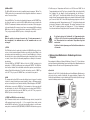
Deutschland: Tel. 0180/5 31 21 16
Mo. - Fr., 8.00 bis 18.00 Uhr
Österreich: Tel. 0 72 42/20 30 60
Mo. - Do. 8.30 bis 12.00 Uhr, 13.00 bis 16.00 Uhr
Fr. 8.30 bis 12.30 Uhr
Schweiz:; Tel. 0848 87 78 11
Mo.- Do. 8.00 bis 12.00 Uhr, 13.00 bis 17.00 Uhr
Fr. 8.00 bis 12.00 Uhr
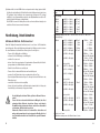
Bestimmungsgemäßer Einsatz des
Meßgerätes VC - 608:
Messung von Gleichspannungen bis maximal 1000 VDC
TRUE RMS (=Echteffektivwert) - Messung von Wechselspannungen bis maximal 750
VACrms
True RMS - Messungen von Mischspannungen (AC + DC) bis max. 750 VACrms/VDC
Messung von Gleich- und Wechselströmen (True rms) bis max. 10 A, max. 3 Min.
lang (gesichert)
Messung von Widerständen bis max. 50 MOhm
Messung von Frequenzen bis max. 5 MHz
Messung des Leitwertes bis 500 nS
3
4
69
Messung von Temperaturen von -20°C bis +1200°C über einen externen Temperatursensor (optional)
Messung der Kapzität von Kondensatoren von ca. 5 nF bis ca. 5000 uF
Durchgangsprüfung (einstellbar bis 5 kOhm akustisch) und Diodentest (auch Zenerdiodentest)
Messung des Puls/Pausenverhältnisses bis 100% und Messung der Pulsbreite bis
200 ms
Eine Messung unter widrigen Umgebungsbedingungen ist nicht zulässig. Widrige
Umgebungsbedingungen sind:
- Nässe oder zu hohe Luftfeuchtigkeit,
- Staub und brennbare Gase, Dämpfe oder Lösungsmittel,
- Gewitter bzw. Gewitterbedingungen wie starke elektrostatische Felder usw.
Eine andere Verwendung als zuvor beschrieben, führt zur Beschädigung des Meßgerätes, außerdem ist dies mit Gefahren, wie z. B. Kurzschluß, Brand, elektrischer
Schlag etc. verbunden. Das gesamte Produkt darf nicht geändert, bzw. umgebaut
werden! Die Sicherheitshinweise sind unbedingt zu beachten!
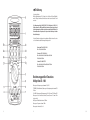
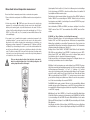
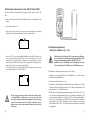
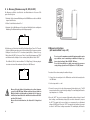
Bedienungselemente
Abbildung (Ausklappseite)
1. Multifunktionsanzeige mit 2 x 5-stelligen Anzeigen (1 x groß, 1 x klein) und Anzeige der Funktionen und Maßeinheiten
2. Drucktastenfeld (Funktionstastenblock) mit 2a Taster "HOLD" 2b Taster "REL"
(Bezugswertmessung) 2c Taster "LIGHT" (Hintergrundbeleuchtung) 2d Taster
MENU (Subfunktionen) 2e Taster "Alt F" (Funktionsumschalttaster) 2f Taster für
Änderungen nach unten 2g Taster Taster für Änderungen nach oben 2h Taster für
die Eingabebestätigung (ENTER)
3. Drehschalter (=Meßfunktionsschalter) zur Einstellung der verschiedenen Betriebsarten (Spannungsmessung, Strommessung usw.)
4. 10-A-Eingang Dieser Meßeingang ist mit 10 A (-Sicherung) abgesichert und für
Gleich- und Wechselströme bis max. 10 A (max. 3 Min. lang mit 10 Min. Pause
zwischen den Messungen) zugelassen.
5. -/r uA / mA-Eingang An diesem Eingang können Gleich- und Wechselströme bis
max. 500 mA gemessen werden (abgesichert mit einer flinken 1-A-Sicherung).
Außerdem ermöglicht dieser Eingang die Zenerdiodenmessung.
68
5
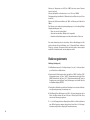
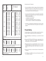
Capacity
5 nF
50 nF
500 nF
5 uF
50 uF
500 uF
5,000 uF
Test period
(approx.)
± (5.0% + 10 digits)
± (2.0% + 10 digits)
± (2.0% + 10 digits)
± (2.0% + 5 digits)
± (2.0% + 5 digits)
± (3.0% + 10 digits)
± (3.0% + 10 digits)
1 pF
10 pF
0.1 nF
1 nF
10 nF
0.1 uF
1 uF
Measuring
frequency
1.1 s
1,350 kHz
1.1 s
1,350 kHz
1.1 s
15 kHz
1.1 s
95 kHz
1.1 s
430 kHz
betw. 1.1 s and 10 s 430 kHz
betw. 1.1 s and 10 s 430 kHz
Continuity tester
5 k Ohm < 5 Ohm for 'Shrt' display
> 15 Ohm for 'OPEn' display
50 k Ohm < 50 Ohm for 'Shrt' display
> 100 Ohm for 'OPEn' display
500 k Ohm < 500 Ohm for 'Shrt' display
> 1 k Ohm for 'OPEn' display
5 M Ohm
< 5 k Ohm for 'Shrt' display
> 10 k Ohm for 'OPEn' display
Measuring pulse width = PW
200 ms
± (0.10% + 5 digits) 10 us
Sensitivity: see frequency measurement
Measuring K type temperature = tolerance of the measuring device
Display in °C
-20 (°C to 0 °C
+ 3 °C
0.1 °C
0 °C to + 150 °C
+ 2 °C
0.1 °C
+ 150 °C to 1,200 °C + 2.0 0% 0.1 °C
Display in °F
Approx. 1.8 x tolerance of °C
66
=
Lesen Sie die Gebrauchsanweisung
CAT III
=
Überspannungskategorie III
Schutzklasse II (doppelte Isolierung)
• Meßgeräte und Zubehör sind kein Spielzeug und gehören somit keinesfalls in Kinderhände !
0.01 Hz
0.1 Hz
1 Hz
10 Hz
100 Hz
Input sensitivity 2 V (AC) rms max., from 5 Hz to 5 MHz
Measuring frequency with display of the alternating voltage (five digits): measuring
tolerance: see alternating voltage
Measuring pulse-pause ratio = DUTY (0.1 ms to approx. 200 ms)
0.1% to 99.9%
± (0.10% + 5 digits) 0.1%
Achtung! Berührungsgefährliche Spannungen! Lebensgefahr!
• Strommessungen dürfen nur in Stromkreisen durchgeführt werden, die selbst mit
10 A abgesichert sind bzw. in welchen keine Spannungen größer als 600
VDC/VACrms auftreten können. Das Meßgerät darf nicht in Installationen der
Überspannungskategorie III nach IEC 664 verwendet werden. Das Meßgerät und
die Meßleitungen sind nicht gegen Lichtbogenexplosionen geschützt.
Measuring frequency / Measuring pulse-pause ratio / Measuring pulse width
± (0.01% + 5 digits)
± (0.01% + 5 digits)
± (0.01% + 5 digits)
± (0.01% + 5 digits)
± (0.01% + 5 digits)
=
=
An audible signal tone will sound for the 'Shrt' display. The resistance value will be
shown in the small display.
50 Hz
500 Hz
50 kHz
500 kHz
5 MHz
in sicherheitstechnisch einwandfreiem Zustand verlassen. Um diesen Zustand zu
erhalten und einen gefahrlosen Betrieb sicherzustellen, muß der Anwender die
Sicherheitshinweise und Warnvermerke beachten ("Achtung!" und "Hinweis!"), die
in dieser Gebrauchsanweisung enthalten sind. Folgende Symbole gilt es zu
beachten:
• In gewerblichen Einrichtungen sind die Unfallverhütungsvorschriften des Verbandes der gewerblichen Berufsgenossenschaften für elektrische Anlagen und
Betriebsmittel zu beachten.
• In Schulen, Ausbildungseinrichtungen, Hobby- und Selbsthilfewerkstätten ist der
Umgang mit Meßgeräten durch geschultes Personal verantwortlich zu überwachen.
• Beim Öffnen von Abdeckungen oder Entfernen von Teilen, außer wenn dies von
Hand möglich ist, können spannungsführende Teile freigelegt werden. Es können
auch Anschlußstellen spannungsführend sein. Vor einem Abgleich, einer Wartung,
einer Instandsetzung oder einem Austausch von Teilen oder Baugruppen, muß
das Gerät von allen Spannungsquellen und Meßkreisen getrennt sein, wenn ein
Öffnen des Gerätes erforderlich ist. Wenn danach ein Abgleich, eine Wartung oder
eine Reparatur am geöffneten Gerät unter Spannung unvermeidlich ist, darf das
nur durch eine Fachkraft geschehen, die mit den damit verbundenen Gefahren
bzw. den einschlägigen Vorschriften dafür (VDE-0100, VDE-0701, VDE-0683) vertraut ist.
• Kondensatoren im Gerät können noch geladen sein, selbst wenn das Gerät von
allen Spannungsquellen und Meßkreisen getrennt wurde.
• Es ist sicherzustellen, daß nur Sicherungen vom angegebenen Typ und der angegebenen Nennstromstärke als Ersatz verwendet werden. Die Verwendung geflickter Sicherungen oder ein Überbrücken des Sicherungshalters ist unzulässig. Zum
Wechsel der Sicherungen trennen Sie das Meßgerät vom Meßkreis und schalten
es aus. Entfernen Sie alle angeschlossenen Leitungen und Prüfspitzen. Nehmen
7
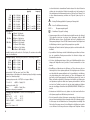
Rectangular
Sinusoidal
triangular
other
0.20 %
0%
0.30 %
0.50 %
1.70 %
b) elektromagnetischen Feldern (Transformatoren, Motore, Spulen, Relais, Schütze,
Elektromagneten usw.)
CF 1
CF 1.414 (=root of 2)
CF 1.73 (=root of 3)
CF 2
CF 3
c) elektrostatischen Feldern (Auf-/Entladungen)
d) Sendeantennen oder HF-Generatoren
AC+DC mixed voltage (TRUE RMS: from 10% to 100% of the measuring range)
500mV
±(2.0%+50digits)
0.01 mV
50 Hz to
1 kHz
±(2.5%+50digits)
1 kHz to
5kHz
±(3.5%+50digits)
5 kHz to
10 kHz
±(4.5%+50digits)
10 kHz to
20 kHz
5V
±(2.0%+50digits)
0.1 mV
50 Hz to
1 kHz
±(2.5%+50digits)
1 kHz to
5 kHz
±(3.5%+50digits)
5 kHz to
10 kHz
nicht spezifiziert
10 kHz to
20 kHz
50 V
±(2.0%+50digits
1mV
50 Hz to
1 kHz
±(2.5%+50digits)
1 kHz to
5 kHz
±(3.5%+50digits)
5 kHz to
10 kHz
nicht spezifiziert
10 kHz to
20 kHz
500 V
±(2.0%+50digits)
10 mV
50 Hz to
1 kHz
±(2.5%+50digits)
1 kHz to
5 kHz
±(3.5%+50digits)
5 kHz to
10 kHz
nicht spezifiziert
10 kHz to
20 kHz
750 V
±(2.0%+50digits)
0.1 V
50 Hz to
1 kHz
±(2.5%+50digits)
1 kHz to
5 kHz
±(3.5%+50digits)
5 kHz to
10 kHz
nicht spezifiziert
10 kHz to
20 kHz
Crest factor of 3 max.
Additional measuring errors for different forms of curve: see alternating ACV and
ACmV voltage.
DCA direct current (uA, mA and A)
5000 uA
±(0.2%+5digits)
500 mA
±(0.2%+5digits)
10 A
±(0.5%+5digits)
0.1 uA
10 uA
1 mA
0.1 uA
10 uA
1 mA
50 Hz to
50 Hz to
50 Hz to
1 kHz
1 kHz
1 kHz
Accurate up to 80% of the measuring range; measuring errors for all ranges from
80% to 100%:
64
• Wenn anzunehmen ist, daß ein gefahrloser Betrieb nicht mehr möglich ist, so ist
das Gerät außer Betrieb zu setzen und gegen unbeabsichtigten Betrieb zu
sichern. Es ist anzunehmen, daß ein gefahrloser Betrieb nicht mehr möglich ist,
wenn
- das Gerät sichtbare Beschädigungen aufweist,
- das Gerät nicht mehr arbeitet und
- nach längerer Lagerung unter ungünstigen Verhältnissen oder
- nach schweren Transportbeanspruchungen.
• Schalten Sie das Meßgerät niemals gleich dann ein, wenn es von einem kalten in
einen warmen Raum gebracht wird. Das dabei entstandene Kondenswasser kann
unter Umständen Ihr Gerät zerstören. Lassen Sie das Gerät uneingeschaltet auf
Zimmertemperatur kommen.
Vorstellung
Dieses Digitalmultimeter mit Multifunktionsanzeige ist mit mehreren Besonderheiten
ausgerüstet, welche manche Messung sinnvoll ergänzen:
a) einer kleinen und einer großen je fünfstelligen Digitalanzeige bis zu einer Auflösung
von 4 Stellen hinter dem Komma (Dezimalpunkt).
b) Bei den Funktionen "D-H" (=Data Hold), "MIN" und "MAX" und "AVG" ist es beispielsweise möglich, einen Meßwert "einzufrieren" bzw. den kleinsten oder größten auftretenden Meßwert oder den Mittelwert (AVG) festzustellen.
The load voltage = voltage drop at the shunt (resistance value) is ascertained from:
measured current x (shunt resistance + fuse resistance)
ACA alternating current (TRUE RMS)
5,000 uA
±(0.75%+20digits)
500 mA
±(0.75%+20digits)
10 A
±(0.75%+20digits)
• Verwenden Sie das Multimeter nicht kurz vor, während oder kurz nach einem
Gewitter (Blitzschlag! / energiereiche Überspannungen!). Achten Sie darauf, daß
Ihre Hände, Schuhe, Kleidung, der Boden, das Meßgerät bzw. die Meßleitungen,
Schaltungen und Schaltungsteile usw. unbedingt trocken sind.
c) Bei der Spannungs- und Strommessung (AC u n d DC), wird egal bei welcher Kurvenform des Meßsignals, der "echte" oder "wahre" Effektivwert (True Rms = wahrer Effektivwert) angezeigt, d.h. auch bei verzerrten Sinuswechselspannungen
bzw. bei Ausgangsspannungen von Einweggleichrichterschaltungen.
d) Mit der Funktion "Hz" können Sie Frequenzen von Meßsignalen bis max. 5 MHz
messen.
e) Mit der Funktion "TEMP" und dem NiCrNi-Fühler (K-Typ) sind Temperaturen von 20°C bis max. +1200°C meßbar.
9
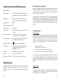
Technical data and measuring tolerances
Technical data
Display .........................................: two 5-digit displays up to 49999, with an automatic display of polarity, symbol displays and measuring units
Max. measuring rate ....................: 2 measurements per second, or slower when measuring the frequency, pulse width and capacity
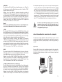
B Anschluß der Meßleitungen
Verwenden Sie für Ihre Messungen stets nur die beiliegenden Meßleitungen bzw. die
Adapter-/Leitungen, welche optional für das DMM erhältlich und somit darauf abgestimmt sind. Achten Sie vor jedem Anschluß auf den Zustand der Anschlußstecker
bzw. Meßspitzen sowie auf die unbeschädigte Isolation.
Die beiliegenden Meßleitungen sind zugelassen für Spannungen bis max. 1000 V. Ihr
Meßgerät, das VC - 608 ist für Spannungen bis max. 1000 VDC bzw. 750 VACrms
ausgelegt. Seien Sie besonders vorsichtig im Umgang mit Spannungen größer 25 V
Wechsel- bzw. 35 V Gleichspannung.
Überschreiten Sie niemals die max. Eingangsgrößen, da sonst durch Beschädigung
des Meßgerätes für Sie Lebensgefahr besteht.
Basic accuracy ............................: 0.05%
Maximum input current AC/DC ...: 10 A
Operating temperature ................: 0°C to +40°C
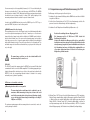
C Inbetriebnahme
Storage temperature....................: -20°C to +60°C (battery removed), rel. LF < 70%
not cond.
C1 Grundeinstellung
Relative air-humidity ....................: from 0 °C to 28 °C: less than 90%, non-condensing from 28 °C to 40 °C: less than 80%, noncondensing
Temperature coefficient ...............: 0.01 x provided accuracy / °C, within the range of
0°C to 18°C and from 28°C to 40°C
+ -
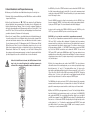
Um eine Meßart auszuwählen, stellen Sie den Drehschalter auf die gewünschte Position. Dadurch wird das Meßgerät eingeschaltet. Schalterstellung "OFF" bedeutet:
Meßgerät ausgeschaltet.
Auto-Power-Off bedeutet automatische Abschaltung des Gerätes in den sog.
"Sleep-Mode" (Bereitschaft oder "Stand-by"). Das Gerät schaltet nach ca. 15 Min
"ab", wenn
keine Taster betätigt werden,
Battery change display ................: '
' from less than approx. 7 V of battery
voltage
der Drehschalter nicht betätigt wird
Power consumption.....................: normal (without light) is approx. 7 mA. AutoPower Off (after approximately 15 mins. on standby): approx. 70 uA. Equipment of (EEPROM):
approx. 7 uA max.
die Auto-Power-Off-Funktion nicht vorher ausgeschaltet wurde.
Battery type .................................: NEDA 1604 9V or 6F22 9V (alkaline)
Weight..........................................: 557 g (with holster and battery)
das Meßgerät keine Meßwertaufzeichnung durchführt,
Die Bereitschaft wird durch das blinkende Symbol "AUTO OFF" angezeigt. Das Meßgerät kann "geweckt" werden, indem irgendein Taster betätigt wird.
Die Funktion "Auto-Power-Off" läßt sich abschalten, indem Sie den Taster "MENU"
betätigen und danach den Taster ENTER. Das Symbol "Auto Off" ist verschwunden.
Das Meßgerät ist nun solange eingeschaltet, bis die Batterie verbraucht (leer) ist.
Measurements (L X W X H) ..........: approx. 204 x 94 x 43 mm (without rubber holster)
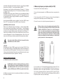
C2 Tastenbelegungen
Measuring tolerances
Information on accuracy is in ± (% of the reading + number of digits = dgt(s)). Accurate for an entire year at a temperature of +23°C ±5°, with a relative air-humidity of
less than 90%, non-condensing. The warm-up period amounts to 1 minute.
62
a) HOLD
Mit jedem Tastendruck (kurzzeitig) schalten Sie die Data-Hold-Funktion ein oder aus.
Data-Hold bedeutet, daß der Meßwert (bzw. das ganze Display) festgehalten ("eingefroren") wird, bis die Funktion Data-Hold wieder ausgeschaltet wird.
11
b) Software
Insert the CD ROM in the appropriate disk drive of your PC. Click on the appropriate
data icon (3.1, '95 or '98) in EXPLORER. Click on 'Set up' and follow the instructions
displayed on the screen. After completing the installation successfully (with restart),
you can click on the 'VC - 608' icon via the program group and work with the software.
c) The interface in the measuring device is activated in the following way:
Press the 'MENU' key. 'AUTO OFF' will flash. 'RSC232C' is shown underneath it.
Press the '>' key once: 'RS232C' flashes. Press the 'ENTER' key as confirmation.
The interface is now connected. The setting will be retained until you switch off the
multimeter (to 'OFF').
d) System prerequisites
Minimum 486/586 processor chip. At least 32 MB RAM. The graphic card must be a
Super VGA at least. Minimum 4 way CD ROM disk drive. Windows operating system:
3.1, '95 or '98
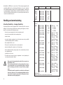
Meßfunktion
Wechselspannung
Gleichspannung
Mischspannung
Wechselstrom
Gleichstrom
Mischstrom
Ohm und LV Ohm
+))) (Durchgangsprfg.)
-I InS
Hz (Frequenzmessg.)
PW (Pulsbreite)
Temperatur
"
"
Hauptdisplay
AC Volt
DC Volt
AC+DC Volt
AC Ampere
"kleines" Display
dBm
Eingangswiderstand in M Ohm
dBm
Shuntwiderstand
(=Nebenwiderstand)
DC Ampere
Shuntwiderstand
AC+DC Ampere
Shuntwiderstand
Widerstandswert
Spannungsanzeige (2,5V oder 0,25V)
"OPEn" od. "Shrt"
Widerstandswert
Kapazität
Spannungsanzeige
Leitwert
Widerstandswert (in Giga - Ohm)
Frequenz
Wechselspannung
Pulsbreite pos. / neg. Puls-Pausenverhältnis
Grad Celsius
Grad Kelvin (absolut)
Grad Fahrenheit
Grad Kelvin
Zenerspannung
Meßstrom
e) Interface parameters
Transfer speed: 9,600 baud.
Data bits : 7
Stop bits : 1
Parity
: none
f) Pfeiltaster "<"
für die Einstellung von Funktionen oder Zahlenwerten nach links, bzw. nach unten
bzw. zurück.
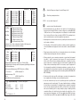
Disposal
g) ENTER
Der Taster ENTER ist hinreichend aus der Computertechnik bekannt und bedeutet
soviel wie Bestätigung der Eingabe.
If the digital multimeter does not function despite an intact electrical supply (9 V
block battery) and fuses, or it is irreparable, then it must be disposed of according to
the applicable legal regulations.
g) Pfeiltaster ">"
für die Einstellung von Funktionen oder Zahlenwerten nach rechts bzw. nach oben
bzw. vor.
C3 Subfunktionen
Correction of faults
a) Bargraphanzeige
Diese Bargraphanzeige ist eine Besonderheit. Unüblicherweise wird hier der Meßwert nicht direkt angezeigt, sondern erfolgt als Binärcode-Anzeige (1-2-4-8-16....16K). Das heißt, daß der augenblickliche Meßwert (als Zahlenwert) im Hauptdisplay umgewandelt in den Binärcode am Bargraphen dargestellt wird.
In purchasing the TRUE RMS VC - 608 digital multimeter, you have acquired a product which has been constructed to incorporate the latest technology. However, problems or faults can still occur. The following guidance is therefore given, which will
enable you to correct some of these faults relatively easily yourself. Be careful to follow the safety advice!
Hinweise!
Meßwerttendenzen (nach oben oder nach unten) sind durch die deutlich höhere
Meßgeschwindigkeit des Bargraphen leichter erkennbar.
Die Bargraphanzeige ist vergleichbar mit dem Zeiger eines Analogmeßinstrumentes, ohne dessen mechanische Nachteile.
60
13
I Zener diode test and temperature measurement
Proceed as follows for measuring zener diodes or semiconductor segments:
1. Connect the black sensing leads to the COM bush and the red sensing lead to the
V bush.
2. Set the rotary switch to '
/ TEMP' and connect the sensors to the object being
measured, (i.e., a voltageless Zener diode), the red sensor to the cathode (identifiable by a coloured ring, point, etc) and the black sensor to the anode. The Zener
voltage of the Zener diode will now be shown in the main display (e.g., 8.1 V for a
ZPD 8.1, or 3.6 V for a 3V6, etc.). The (constant) test current will be shown as 1 mA
in the small display.
3. If you want to test a 'normal' diode segment or semiconductor segment in the
conducting direction**, you must connect the red sensor to the anode and the
black sensor to the cathode. Insofar as the semiconductor is not defective, you
will measure a voltage of approx. 0.25 V (germanium) or 0.7 V (silicium or 250 mV,
or 700 mV). If you now exchange the sensor, i.e., red to the cathode and black the
anode, then you will be able to check the so-called inverse direction of the diode
route). The diode is in order if 'OL' is shown. On the other hand, if a voltage value
is shown, then you have either incorrectly connected the object being measured
or it is defective, or it is a Zener diode.
Take care when testing the diode, that the diode or the switch which is possibly integrated into it -is definitely voltageless. All
existing capacities must be discharged.
(Speicherplatz) "Addr" aus (0 bis 9), führen Sie die Messung durch und bestätigen
Sie die Speicherung mit "ENTER". In dieser Art und Weise können Sie sämtliche 10
Speicherplätze mit Zahlenwerten belegen.
Zum Abrufen der Speicherwerte betätigen Sie erneut den Taster "MENU", wählen die
Funktion "RECALL" aus und bestätigen mit "ENTER". Wählen Sie die (evtl. notierte)
Speicheradresse aus (Addr 0...9) und betätigen Sie nochmals "ENTER". Der gespeicherte Meßwert wird angezeigt.
Um die Subfunktion (STORE oder RECALL) zu verlassen, betätigen Sie den Taster
"HOLD" oder den Taster "ALT F" oder zweimal den Taster "MENU", bzw. den Drehschalter.
f) GO /NG (go / No go-Funktion = eine Art Vergleichsmessung)
Mit dieser Subfunktion können Sie Vergleichsmessungen durchführen, wobei die
Zustände "FAIL" und "PASS" angezeigt werden. Fail bedeutet, der augenblickliche
Meßwert liegt außerhalb des eingestellten Referenzbereiches. Pass bedeutet, der
augenblickliche Meßwert liegt innerhalb des Referenzbereiches. Die Referenzwerte
sind abspeicherbar (Speicheradressen "Addr 0...9").
Betätigen Sie den Taster "MENU". "AUTO OFF" blinkt. Wählen Sie die Subfunktion
"GO / NG" aus und bestätigen Sie mit "ENTER". Sie befinden sich nun im "REF"Modus (Symbol "REF" unter "GO/NG" oben rechts). Im kleinen Display wird die
Speicheradresse für evtl. vorhandene Referenzwerte angezeigt.
Es gibt nun zwei Wege, eine Referenzwert einzugeben: f1 die Eingabe über eine vorher belegte Speicheradresse oder f2 die direkte Eingabe.
f1) Wählen Sie die Speicheradresse aus und bestätigen Sie mit "ENTER". Der abgelegte Referenzwert wird im Hauptdisplay angezeigt und Sie können mit der Eingabe
der Bereichsgrenzen (Toleranzen) in "+ %" und "- %" fortfahren. "+%" erscheint
oben rechts in der Anzeige und die kleine Anzeige blinkt. Geben Sie den Toleranzbereich in 0,1 oder 0,2 oder 0,5 oder 1,0 oder 2,0 oder 5,0 oder 10 oder 20 oder 50 oder
100% ein und bestätigen Sie mit "ENTER". "-%" erscheint oben rechts in der Anzeige und die kleine Anzeige (unten) blinkt erneut. Geben Sie auch hier den gewünschten %-Wert ein und bestätigen Sie erneut mit "ENTER".
Die GO/NG-Funktion wurde gestartet. Befindet sich der augenblickliche Meßwert
innerhalb der eingestellten Toleranzgrenzen, so wird "PASS" angezeigt. Befindet sich
der augenblickliche Meßwert dagegen außerhalb der eingestellten Toleranzgrenzen,
so wird "FAIL" angezeigt.
f2) Betätigen Sie den Taster "ENTER" ca. 1s lang. Die erste (linke) Ziffer blinkt. Geben
Sie die linke Ziffer Ihres gewünschten Referenzwertes (bei 35,000 VDC z.B. die Ziffer
3) ein und bestätigen Sie mit ENTER. Die zweite Ziffer blinkt. Geben Sie die zweite
Ziffer Ihres REF-Wertes (Beispiel: 5 von 35,000 VDC) ein und bestätigen Sie. Die dritte
Ziffer blinkt usw.
Nach Eingabe der fünften Stelle bestätigen Sie (ENTER) und gehen zur Einstellung
der Polarität über (+ oder -). Nach erfolgter Eingabe bestätigen Sie mit ENTER. Dar-
58
15
6. You must press the 'Alt F' key again (for the second time) for the LV Ohm function
(=resistance measurement of the smallest voltage). The normal display for measuring resistance will appear, with the difference that the measured voltage here only
amounts to 0.25 V. For this reason, no semiconductor must be introducedwhich
might falsify a measured value. In this way, measurements can also be made
directly onto a board when the switches are voltageless. You must connect both
measuring sensors together to manually set the measuring range, wait until the
display stands at'00.xx' (x for any value from 07 to 2) and then set the desired range with the '>' arrow key.
G Measuring capacity and conductance
Discharge every condenser before you connect it to the measuring device. Short-circuiting of condensers can result in high energy discharges. Take care in rooms which contain dust, combustible gases, steam or liquids, or which could contain them. ( Danger of explosion!
Do not touch the connections when condensers are carrying voltages greater than 35 V (DC) or 25 V(AC). Caution: Danger to life!
Do not carry out any measurements on condensers in which switches or switch components are integrated.
Proceed as follows for measuring condensers of up to 4,999 uF max.:
1. Connect the black sensing lead to the COM bush and the red sensing lead to the
'V' bush.
2. Set the rotary switch to '-)I- / nS'.
3. Connect the measuring sensors to the condenser, which must be voltageless. Pay
attention to the '+' and '-' poles when measuring electrolyte condensers (Elko).
Press the '>' key for manually setting a measuring range. As a result, the autmatic
range selection will be switched off and the RANGE symbol for manually selecting
the range will appear below on the left (in the display). Set the desired range with
the '>' arrow key.
4. Proceed as follows for measuring the conductance (= complement of the resistance '1/Ohm') measured in S (Siemens) or in nS (nano-Siemens) in this case:
Press the 'Alt F' key once. As a result, the resistance will be shown in G Ohm (means
Giga Ohms) in the lower, smaller display and the conductance will be shown in the
main display in nS. Only one range is available for measuring the complement (conductance).
56
=~V
= Gleich- und Wechselspannungsmessung
=~mV
= mV (milli = exp.-3) Gleich- und Wechselspannungsmessung
Ohm +))) LV Ohm = Widerstandsmessung, Durchgangsprüfung
-II-/nS
= Kapazitätsmessung / Leitwertmessung
Hz/PW
= Frequenzmessung und Pulsbreitenmessung
/TEMP
=~uA
= Zenerdioden- / Temperaturmessung
= uA (u = exp.-6) Gleich- und Wechselstrommessung
=~mA
= mA Gleich- und Wechselstrommessung
=~ A
= A Gleich- und Wechselstrommessung
b) 10-A-Buchse
Für Gleich- oder Wechselstrommessungen bis max.! 10 A muß hier die rote Meßleitung eingesteckt werden.
Der Meßfunktionsschalter darf bei der Strommessung auf keinen
Fall auf Spannungsmessung (mV oder V) stehen.
c) -I<- /uA/mA-Buchse
Für Gleich- oder Wechselstrommessungen bis max. 500 mA muß hier die rote
Meßleitung eingesteckt werden.
Außerdem wird diese Buchse in Verbindung mit der COM-Buchse für Diodenmessungen (Zenerdiode) benötigt. Bei der Temperaturmessung über den (optionalen)
Sockel wird diese Buchse in Verbindung mit der V-Buchse und der COM-Buchse
benötigt.
d) COM = Common-Buchse
Hier muß für sämtliche Messungen die schwarze Meßleitung eingesteckt werden
(Common-Buchse bedeutet Minus- oder "-" oder Masse-Buchse)
e) V - Buchse
In diese Buchse muß die rote Meßleitung gesteckt werden, wenn Sie Spannungsoder Frequenzmessungen, Durchgangsprüfungen, Widerstands-, Leitwert- und
Kapazitätsmessungen durchführen wollen.
D Gebrauchslage
Betreiben Sie das Multimeter stets so, daß Sie die Flüssigkeitskristallanzeige (englisch kurz: LCD) lesen können bzw. die Digitalanzeige nach oben zeigt. Zur besseren
Ablesung im Standbetrieb befindet sich an der Geräterückseite ein aufklappbarer
Standbügel.
17
E Measuring A (measuring current, AC, DC and AC+DC).
Proceed as follows for measuring direct, alternating or mixed currents in A up to 10A
max:
1. Connect the black sensing lead to the COM bush and the red sensing lead to the
A bush.
2. Set the rotary switch to 'A=~'.
3. Connect the sensing leads in series to the object being measured (see following
illustration). The measured value will be shown in the large display.
B mV-Spannungsmessung
(mV, sprich: millivolt = exp. - 3 V)
4. Press the 'Alt F' key once for measuring alternating currents (AC) in A. Instead of a
direct current, an alternating (AC) current can now be measured in A. If you the
press the 'Alt F' key again (for the second time), you can measure the so-called
mixed currents (AC+DC) in A. Press the Alt F' key again (for the third time) if you
want to return to direct current measurement (DCA).
The A range (10 a) is protected with a rapid-acting 15A 'high energy' fuse and has
a secondary resistance (shunt) of 0.01 Ohm.
Überschreiten Sie auf keinen Fall die max. zulässigen Eingangsgrößen, auch nicht bei der Messung von überlagerten Gleichspannungen (z.B. Brummspannung). Max. 250 VDC / VAC rms.
Berühren Sie keine Schaltungen oder Schaltungsteile, wenn Sie
höhere Spannungen als 25 VACrms oder 35 VDC darin messen.
Zur Messung von Kleinstspannungen gehen Sie wie folgt vor:
A
1. Verbinden Sie die rote Meßleitung mit der V/Ohm-Buchse und die schwarze
Meßleitung mit der COM-Buchse.
2. Stellen Sie den Drehschalter auf ~=mV.
3. Verbinden Sie die Meßspitzen mit dem Meßobjekt (Last, Schaltung usw.). Der DCMeßwert wird im großen Display angezeigt. In der kleinen Anzeige wird die Eingangsimpedanz von > 1 G Ohm angezeigt.
Do not measure currents in current circuits where voltages greater than 600 V(DC) or V(AC) rms can occur, because this could
result in the measuring device being damaged and your ilfe being
at risk. Do not measure currents over 10A (= 4 mA) in the A area.
Only measure current circuits which are themselves protected by
16 A (fuses).
54
4. Zur Messung von mV-Wechselspannungen betätigen Sie den Taster "ALT F" einmal. Statt einer mV-Gleichspannung kann nun eine mV-Wechselspannung ("AC")
gemessen werden. Betätigen Sie den Taster "ALT F" ein weiteres (zweites) Mal, so
können Sie sog. Mischspannungen (AC+DC) in mV messen. Wenn Sie zur Gleichspannungsmessung "mVDC" zurückkehren wollen, betätigen Sie ein weiteres
(drittes) Mal den Taster "ALT F". In der kleinen Anzeige wird jeweils der dBm-Wert
mit abgebildet.
19
respective dBm value. The mV range (up to 2,500 mV for DC and up to 500 mV for
AC) has an input resistance of more than 1,000 MOhm. The measured voltage is
negative or the sensing leads have been exchanged if a minus '-' sign is visible in
front of the respective measured value.
Advice!
Due to the fact that the measuring input is very sensitive, it could be that any
measured values will be displayed when the sensing leads are disconnected
(not connected to an object being measured). This 'appearance' is normal and
will disappear as soon as you carry out your measurement.
C Measuring uA (measuring current, AC, DC and AC+DC)
Proceed as follows for measuring direct, alternating or mixed currents:
Messen Sie keine Ströme in Stromkreisen, in welchen Spannungen größer 600 VDC bzw. VACrms auftreten können, damit das
Meßgerät nicht beschädigt wird und dadurch für Sie Lebensgefahr bestehen kann. Messen Sie im uA-Bereich auf keinen Fall
Ströme über 5000 uA (= 5 mA).
D mA - Messung (Strommessung, AC, DC, AC+DC)
Zur Messung von Gleich- oder Wechsel- oder Mischströmen in mA bis max. 500 mA
gehen Sie wie folgt vor:
1. Verbinden Sie die schwarze Meßleitung mit der COM-Buchse und die rote Meßleitung mit der uA/mA-Buchse.
2. Stellen Sie den Drehschalter auf "mA=~".
1. Connect the black sensing lead to the COM bush and the red sensing lead to the
uA/mA bush.
3. Verbinden Sie die Meßleitungen in Serie mit dem Meßobjekt (siehe nachfolgende
Abbildung). Der Meßwert wird im großen Display angezeigt.
2. Set the rotary switch to 'uA=~'.
3. Connect the sensing lead in series to the object being measured (see the following
illustration). The measured value will be shown in the large display.
4. Zur Messung von -mA-Wechselströmen betätigen Sie den Taster "Alt F" einmal.
Statt eines mA-Gleichstromes kann nun ein mA-Wechselstrom (AC) gemessen
werden. Betätigen Sie den Taster "Alt F" ein weiteres (zweites) Mal, so können Sie
sog. Mischströme (AC+DC) in mA messen. Wenn Sie zur Gleichstrommessung
"mADC" zurückkehren wollen, betätigen Sie ein weiteres (drittes) Mal den Taster
"Alt F".
4. Press the 'ALT F' key once for measuring uA alternating currents. Instead of a uA
direct current, a uA alternating current (AC) can now be measured. If you press the
'Alt F' key again (for the second time), you can measure the so-called mixed currents (AC+DC) in uA. Press the 'Alt F' key again (for the third time) if you want to
return to the 'uADC' direct current measurement.
Der mA-Bereich (500 mA) ist mit einer flinken 1-A-Sicherung abgesichert und weist
einen Nebenwiderstand (Shunt) von 1 Ohm auf.
mA
The uA range (5,000 uA) is protected by a rapid-acting 1A fuse and has a secondary
resistance (shunt) of 100 Ohm. This value will also be shown in the small display.
Messen Sie keine Ströme in Stromkreisen, in welchen Spannungen größer 600 VDC bzw. VACrms auftreten können, damit das
Meßgerät nicht beschädigt wird und dadurch für Sie Lebensgefahr bestehen kann. Messen Sie im mA-Bereich auf keinen Fall
Ströme über 500 mA (= 0,5 A).
52
21
Carrying out measurements
F Widerstandsmessung (Normal Voltage und Low Voltage
LV) und Durchgangsprüfung
A Measuring voltage (DC, AC and AC+DC)
Do not exceed the maximum permissible input magnitudes (AC)
rms under any conditions, even when measuring overlaid direct
voltages (e.g., hum or ripple voltages). Max. 1,000 VDC or 750 VAC
rms. Do not touch any switches or switch components if you are
measuring voltages greater than 25 V (AC)rms or 35 V (DC) therein.
Proceed as follows for measuring voltages.
1. Connect the red sensing lead to the V/Ohm bush, and the black sensing lead to
the COM bush.
Vergewissern Sie sich, daß alle zu messenden Schaltungsteile,
Schaltungen und Bauelemente sowie andere Meßobjekte unbedingt spannungslos sind.
Zur Widerstandsmessung gehen Sie wie folgt vor:
1. Verbinden Sie die schwarze Meßleitung mit der COM-Buchse und die rote Meßleitung mit der V-Buchse.
2. Stellen Sie den Meßfunktionsschalter auf Widerstandsmessung "Ohm +))) LV
Ohm". Überprüfen Sie die Meßleitungen auf Durchgang, indem Sie beide Meßspitzen miteinander verbinden.
2. Set the rotary switch to =~V.
3. Wenn Sie den Meßbereich von Hand einstellen wollen (manuell nicht automatisch),
so müssen Sie die beiden Meßspitzen miteinander verbinden, warten bis die
Anzeige auf "00.xx" steht (x für irgendeinen Wert um 07 bis 2) und dann mit dem
Pfeiltaster ">" den gewünschten Bereich einstellen.
3. Connect the sensors to the object being measured (load, switching, etc.). The DC
measured value will be shown in the large display. The small display will show the
input impedance (10.5 M Ohm to 10.05 M Ohm depending on the range).
4. Nun verbinden Sie die Meßspitzen mit dem Meßobjekt. Nach einer kurzen Stabilisierungsphase wird Ihnen der Widerstandswert angezeigt. In der kleinen Anzeige
steht 2,5 V für die Meßspannung zu lesen.
4. You switch over to measuring TRUE RMS alternating voltage "AC" (up to 10 kHz),
by pressing the 'ALT F' key. The alternating voltage's dBm value will additionally
be shown in the small display.
Hinweis!
Wenn Sie eine Widerstandsmessung durchführen, achten Sie darauf, daß die
Meßpunkte, welche Sie mit den Meßspitzen zum Messen berühren, frei von
Schmutz, Öl, Lötlack oder ähnlichem sind. Solche Umstände können den
Meßwert verfälschen.
Bei Widerständen größer ca. 1 MOhm kann es sein, daß die Anzeige etwas Zeit
benötigt, um sich zu stabilisieren ("einzustellen"). Sobald "OL" im Display
erscheint und der Bargraph alle Segmente anzeigt, haben Sie den Meßbereich
überschritten, bzw. die Meßstrecke ist unterbrochen.
5. You can measure mixed voltages and display the real rms current (true rms) by
pressing the 'ALT F' key again (2nd)(also up to 10kHz). The small display will also
show the associated dBm value here.
6. You return to measuring the direct voltage 'DC', by pressing the 'ALT F' key again
(3rd).
The input resistance (impedance) amounts to approximately 10 MOhm. If a minus '-'
sign is visible in front of the respective measured value, then either the measured
(direct) voltage is negative or the sensing leads have been exchanged.
Advice!
Due to the fact that the measuring input is very sensitive, it could be that any
measured values will be displayed when the sensing leads are disconnected
(not connected to an object being measured). This 'appearance' is normal and
will disappear as soon as you carry out your measurement.
50
5. Zur Funktion Durchgangsprüfung "+)))" betätigen Sie den Taster "Alt F" einmal.
Daraufhin wird links unten das Symbol "+)))" eingeblendet. Bei der Durchgangsprüfung ertönt je nach Bereich bei Anzeige des Symbols "Shrt" (=Short = Kurzschluß) ein akustisches Signal. Die Anzeige des Widerstandswertes erfolgt in der
kleinen Anzeige. Sobald Sie auf Durchgangsprüfung umgeschaltet haben, befinden Sie sich in der manuellen Bereichswahl (kein Auto-Range möglich), erkennbar
am Symbol RANGE schräg über "+)))". Der gewünschte Meßbereich läßt sich nun
einstellen.
Messen Sie keine geladenen Kondensatoren, da sonst durch eine
mögliche Entladung Ihr Meßgerät zerstört werden kann.
23
You are now ready to set the range limits (tolerances) in '%'. Proceed with setting the
tolerances as described for 'f1' above and then press the ENTER key. The GO/NG
function has been started. 'PASS' will be displayed if the momentary measured value
lies within the pre-set tolerance limits. In contrast, 'FAIL' will be displayed if the
momentary measured value lies outside the pre-set tolerance limits.
H Frequenzmessung und Pulsbreitenmessung Hz / PW
In order to quit the GO/NG sub-function, press the 'HOLD' key or the 'ALT F' key, or
press the 'MENU' key twice or turn the rotary switch.
2. Stellen Sie den Drehschalter auf "Hz / PW". In der Hauptanzeige steht die Frequenz zu lesen in der kleinen Anzeige die Wechselspannung.
Zur Messung einer Frequenz gehen Sie wie folgt vor:
1. Verbinden Sie die schwarze Meßleitung mit der COM-Buchse und die rote Meßleitung mit der V-Buchse.
3. Verbinden Sie die Prüfspitzen mit dem Meßobjekt (Generator o.ä.).
g)RANGE (manual selection of range)
If the measuring device is in the 'Auto Range' mode, then it will automatically switch
over to the respective measuring range. Press the '>' arrow key once. You are now in
'manual selection of range' mode, which is visible by the 'RANGE' symbol in the display's bottom left-hand corner. You can move the measuring range one step higher
every time you press on the '>' arrow key again, which is visible by the decimal point
being shifted towards the right. There are four positions for the decimal point. The
automatic range selection will be reactivated when you go beyond the fourth position (on the right).
Beachten Sie unbedingt die max. Eingangsgrößen!
Bei Spannungen größer 25 VAC bzw. 35 VDC besteht bei
Berührung Lebensgefahr.
Schalten Sie während der Messung nicht auf eine andere Meßfunktion bzw. auf einen anderen Bereich um. Beim Weiterschalten
unter Spannung (energiereich) kann ein Abrißfunke entstehen, der
die Leiterbahnen im Innern des Meßgerätes unwiderruflich zerstören kann. Außerdem können Sie durch die Zerstörung des
Meßgerätes gefährdet werden.
The manual range selection can also be activated with the lefthand arrow key, but it cannot be set.
i) RS-232C
The 'RS232C' symbol also appears when the 'MENU' key is pressed. Bi-directional
communication with a connected IBM-compatible PC containing appropriate (preloaded) software will be started, when you click on this symbol and confirm it with
ENTER. For this, the corresponding infra-red interface is located in the casing's
underside (secure, 'galvanic' separation).
C4 References for switches or bushes
a) Measuring function switch or rotary switch
The measuring function switch must not be adjusted in any circumstances whilst measuring is being done, because this could
result in the measuring device being destroyed (breakage signal),
or you could be put in extreme danger from voltages exceeding 25
V (AC)rms or 35 V (DC).
The various measuring ranges which are arranged here in a semi-circle, can be selected by turning the switch:48
4. Mit dem Taster "Alt F" können Sie auf die Pulsbreitenmessung "PW" umschalten.
Wird der Taster einmal betätigt, erfolgt die Messung der positiven Flanke (PULSE
+). Wird der Taster ein weiteres Mal betätigt, erfolgt die Messung der negativen
Flanke (PULSE -). Wird der Taster "Alt F" ein weiteres Mal betätigt, so kehren Sie
zur Frequenzmessung zurück. Das Puls-Pausenverhältnis (= DUTY in %) wird im
kleinen Display angezeigt, die Pulsbreite in ms (Halbwelle) im Hauptdisplay.
25
b) MIN and MAX
The MIN or MAX sub-functions detect amplitude jumps from approx. 100 ms. The
'PEAK' sub-function is recommended for detecting quicker alterations to measured
values. Proceed as follows:
Press the MENU key. The sub-function display block appears and 'AUTO OFF' flashes. Using the arrow keys, select the MIN or MAX sub-function and confirm it with
'ENTER'. The maximum or minimum value function is now started. The display given
in the main display will be renewed every time a new maximum (MAX) or minimum
(MIN) value occurs. You can quit this function by pressing the 'HOLD' key or the 'ALT
F' key, or by pressing the 'MENU' key twice, or turning the rotary switch.
Advice!
When the polarity is exchanged (reversed sign '-') during measurements of
direct magnitudes, the minimum value and the maximum value are also
exchanged.
c) PEAK
The PEAK sub-function (for peak value) is similar to the MIN-MAX function, but it serves here to detect measured signals that alter very quickly (less than 100 ms), such
as starting currents from machinery (e.g., motors for model-building), etc. However,
this sub-function is only possible whilst measuring direct magnitudes (direct voltage
or current): it cannot be used for alternating magnitudes nor during the other measuring functions.
Press the MENU key. "AUTO OFF" will flash. Select the "+PEAK" sub-function (for
rising sides) or "-PEAK" (for falling sides) and confirm with "ENTER". The PEAK-function has been initiated. Each new ultimate value will be captured, recorded (frozen,
similar to Data Hold) and displayed. To quit the sub-function, press the "HOLD" key
or the "ALT F" key, or press the "MENU" twice, or activate the rotary switch.
d) AVG
The average sub-function (AVG = mean value display) serves to improve the reading
of faded, or strongly fluctuating, measured signals. In doing so, 100 measured signals are continuously detected, added, divided by 100 and displayed. 'AUTO OFF'
will flash when you press the 'MENU' key. The determination of the mean value will
be started when you select the 'AVG' sub-function and confirm it with 'ENTER'. In
order to quit the sub-function, press the 'HOLD' key or the 'ALT F' key, or press the
'MENU' key twice or turn the rotary switch.
4. Zur Messung von Temperaturen im Bereich von -20°C bis max. 1200°C ist ein
Temperaturadapter und ein K-Typ-Sensor erforderlich. Beide sind optional erhältlich. Verbinden Sie den Adapter (3-polig) polungsrichtig mit den Buchsen "
u.mA", "COM" und "V". Anschließend verbinden Sie den K-Typ-Sensor polungsrichtig mit dem Temperaturadapter (breiter und schmaler Messerkontakt). Betätigen Sie nun den Taster "Alt F" einmal. Die Haupt-Anzeige springt um von der Zenerdiodenmessung auf die Temperaturmessung in "°C". In der kleinen Anzeige wird
die absolute Temperatur in Kelvin angezeigt. Ein weiterer Tastendruck auf den
Taster "Alt F" bewirkt die Anzeige der Temperatur in "°F" in der Hauptanzeige.
Auch hier wird im kleinen Display die absolute Temperatur in Kelvin angezeigt.
Es gilt zu beachten, daß "außerhalb" des Temperaturbereiches
+18°C bis +28°C (= Bereich der garantierten Meßgenauigkeit) nur
das Thermoelement der zu messenden Temperatur ausgesetzt
werden darf.
Schließen Sie keine Spannungen an. Das Gerät kann dadurch zerstört werden.
J Gebrauch des Multimeters in Verbindung mit einem
Computer
Eine umfangreiche Windows-Software für Windows 3.1x bzw. '95 / '98 und die dazugehörige Infrarotschnittstellenleitung liegen dem Meßgerät bei. Grundkenntnisse im
Umgang mit einem PC und dessen Programmierung sind erforderlich.
a) Anschluß
Verbinden Sie die RS-232-Schnittstellenleitung mit dem Multimeter (Gehäuseunterseite) und mit einer seriellen Schnittstelle des ausgeschalteten Computers. Die
Schnittstelle am Multimeter ist eine bi-direktionale IR-Schnittstelle (Vorteil: keine galvanische Verbindung zwischen Computer und Meßgerät).
e) STORE and RECALL (record and replay)
Up to 10 measured values can be recorded with the storage function (store) and filed
in 10 numbered storage locations (0 ..... 9). You can read off these stored contents
with the RECALL sub-function. The stored contents will be retained , even if the measuring device is switched off (OFF) (EEPROM). 'AUTO OFF' will flash when you press
46
27
b) REL
When measuring a reference value, the difference between the held and the momentarily measured value is displayed to you. This special function is particularly helpful
when ascertaining the lower resistance without the sensing leads' resistance, or with
measured magnitudes that alter slowly.
The function is switched on by pressing the 'REL' key. As a result, the REL symbol
appears in the display's top line. When measuring the resistance, the DMM switches
to the highest range. The 'OL' display disappears by pressing the REL key and is set
to '00.000'. You can quit this function by pressing the REL key again.
Advice!
The REL function is only active when numerical values are being displayed. For
example, the function cannot be called up during the continuity test.
c) LIGHT
The background lighting is switched on or off every time the 'LIGHT' key is pressed.
Due to the relatively high power consumption, the illumination should only be switched on for a short time and switched off again as quickly as possible, in order to
save energy. The illumination will be automatically switched off after approximately
30 seconds if you do not press the key again after switching on.
d) MENU
Press the 'MENU' key. As a result, the so-called sub-functions will appear in the
upper display block. Press the key again and the sub-functions will disappear from
the display again. The following sub-functions can be called up after one another in
the display block: AUTO OFF (automatic switch-off) - RS 232C (switching on the
interface) - MAX (maximum value registration*) - MIN (minimum value registration*) +PEAK (positive peak value registration*) - -PEAK (negative peak value registration*)
- AVG (average value registration*) - RECALL (redisplaying stored measured values) STORE (storing measured values) - GO/NG (a type of comparative measurement).
The respective sub-function that has been called up will flash. Selection is made by
using the arrow keys (< = back and > = forward). The display block will disappear
again if you press the 'MENU' key once more and you return to the momentary display.
e) ALT-F
This key supports the selecting of alternative displays or measuring processes. For
example, a decibel measurement can be made during a voltage measurement, or the
automatic range selection (in connection with '>' and '<') can be switched off and the
measuring range (RANGE) can be set manually, etc.
44
Fehler
Mögliche Ursache
keine Strommessung möglich
Sicherungen für die Strombereiche i.O.?
Haben die Meßleitungen einen sicheren
Kontakt in den Meßbuchsen?
Befinden sich die Meßleitungen in der Abzw. uA/mA-Buchse und COM?
Keine Anzeige bei
eingeschaltetem Gerät
Ist die Batterie verbraucht?
Hat das Meßgerät nach 15-Min-Nichtgebrauch automatisch abgeschaltet?
Beim Öffnen von Abdeckungen oder Entfernen von Teilen, außer
wenn dies von Hand möglich ist, können spannungsführende Teile freigelegt werden. Es können auch Anschlußstellen spannungsführend sein. Vor einem Abgleich, einer Wartung, einer Instandsetzung oder einem Austausch von Teilen oder Baugruppen, muß
das Gerät von allen Spannungsquellen und Meßkreisen getrennt
sein, wenn ein Öffnen des Gerätes erforderlich ist. Wenn danach
ein Abgleich, eine Wartung oder eine Reparatur am geöffneten
Gerät unter Spannung unvermeidlich ist, darf das nur durch eine
Fachkraft geschehen, die mit den damit verbundenen Gefahren
bzw. den einschlägigen Vorschriften dafür (VDE 0100, VDE-0701,
VDE-0683) vertraut ist.
Kondensatoren im Gerät können noch geladen sein, selbst wenn
das Gerät von allen Spannungsquellen und Meßkreisen getrennt
wurde.
Wartung und Kalibrierung
Um die Genauigkeit des Multimeters über einen längeren Zeitraum zu gewährleisten, sollte es jährlich einmal kalibriert werden. Die Kalibrierung kann von unserer
Kalibrierstelle im "Service 2000" kostengünstig durchgeführt werden.
Der Sicherungswechsel ist unter den Sicherheitsbestimmungen beschrieben. Den
Batteriewechsel finden Sie unter "Gebrauch des Multimeters A".
Zur Reinigung des Gerätes bzw. des Display-Fensters nehmen Sie ein sauberes, fusselfreies, antistatisches und trockenes Reinigungstuch.
Verwenden Sie zur Reinigung keine carbonhaltigen Reinigungsmittel oder Benzine, Alkohole oder ähnliches. Dadurch wird die
Oberfläche des Meßgerätes angegriffen. Außerdem sind die
Dämpfe gesundheitsschädlich und explosiv. Verwenden Sie zur
Reinigung auch keine scharfkantigen Werkzeuge, Schraubendreher oder Metallbürsten o.ä..
29
f) In addition, the DMM can be connected to a PC by using an appropriate cable
(optionally available) via the uni-directional, IR interface on the case's underside.
After installing appropriate software in the PC (optionally available), communication
is possible between the digital multimeter and the PC (in both directions = bi-directional). The VC 608 is universally usable: not only in the hobby area but also in professional or educational areas, etc.
Handling and commissioning
A Inserting the battery - changing the battery
Your measuring device must be equipped with a 9 V block battery if it is to function
faultlessly. You must change the battery when a battery symbol appears on the display. Do so by observing the following procedure:
- disconnect your measuring device from the measuring circuit ,
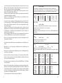
Meßbereich
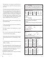
500 mV
2500 mV
5V
50 V
500 V
1000 V
500 mV
5V
0,01 mV
0,1 mV
0,1 mV
1 mV
10 mV
0,1 V
±(1,0%+20dgts)
±(1,5%+20dgts)
±(2,0%+20dgts)
±(3,0%+20dgts)
0,01 mV
1 kHz
5 kHz
10 kHz
±(0,75%+20dgts)
±(1,00%+20dgts)
0,1 mV
50 Hz bis 500 Hz
500Hz bis
5kHz
(mind. 10% Anzeige)
5kHz bis
10kHz
(mind.10% Anzeige)
10 kHz bis 20 kHz
1 mV
50 Hz bis 500 Hz
500Hz bis
5kHz
(mind. 10% Anzeige)
5kHz bis
0kHz
(mind. 10% Anzeige)
10 kHz bis 20 kHz
10 mV
50 Hz bis 500 Hz
500 Hz bis
5 kHz
(mind. 10% Anzeige)
5 kHz bis
10 kHz
(mind.10% Anzeige)
10 kHz bis 20 kHz
0,1 V
50 Hz bis 500 Hz
500Hz bis
5kHz
(mind. 10% Anzeige)
5kHz bis
10kHz
(mind.10% Anzeige)
10 kHz bis 20 kHz
nicht spezifiziert
50 V
- Disconnect the used battery from the connecting clip and
±(0,75%+20dgts)
±(1,0%+20dgts)
- replace the battery with an unused one of the same type.
±(2,0%+20dgts)
- After completing the battery change, replace the connected battery in the battery compartment and
nicht spezifiziert
500 V
- Be careful when closing the battery compartment to avoid squashing the
connecting clip's leads (red / black).
42
±(0,05%+5dgts)
±(0,05%+5dgts)
±(0,05%+5dgts)
±(0,05%+5dgts)
±(0,05%+5dgts)
±(0,05%+5dgts
±(2,00%+20dgts)
- unscrew the battery compartment cover's fastening screws using a suitable
screwdriver (Phillips posidrive screwdriver).
Never operate the measuring device when it is in an opened condition! Danger to life!
Do not leave any used batteries in the measuring device, because
even sealed batteries can corrode and thereby release chemicals
which can damage your health or destroy the battery compartment.
Used batteries must be regarded as special waste and they must
therefore be disposed of in an environmentally friendly way. Special, collection receptacles are provided for this purpose by specialist dealers and at recycling depots.
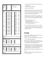
Frequenz
Wechselspannung (TRUE RMS = Echteffektivwert: von 10% bis 100% des Meßbereiches)
- switch it off and
- carefully re-close the cover.
Auflösung
Gleichspannung
- remove the sensing leads from the measuring device,
- Now, carefully lift off the cover.
Genauigkeit
±(0,75%+20dgts)
±(1,00%+20dgts
±(2,00%+20dgts)
nicht spezifiziert
1000 V
±(0,75%+20dgts)
±(1,00%+20dgts)
±(2,00%+20dgts)
nicht spezifiziert
50 Hz
bis
bis
bis
bis
1 kHz
5 kHz
10 kHz
20 kHz
Crestfaktor max. 3
Zusätzlicher Meßfehler bei unterschiedlichen Kurvenformen
31
After changing the fuses, close the casing and screw it carefully together in reverse order. Switch the device on again after the housing has been closed and screwed in securely.
• Be particularly careful when dealing with alternating voltages greater than 25 V (AC) or direct voltages greater than 35 V (DC). Even at these voltages, you can
receive an extremely dangerous electric shock by touching electrical leads. Therefore, switch off the voltage source to start with, connect the measuring device with
the connections of the voltage source to be measured, tune the measuring device
to the requisite voltage-measuring range and subsequently switch on the voltage
source. After completing the measurement, switch off the voltage source and
remove the sensing leads from the connections to the voltage source.
• Before every measurement of voltage, ensure that the measuring device is located
in the voltage-measuring range.
• The sensors must be removed from the object which has been measured, before
every change of measuring range.
• Before taking any measurement, check your measuring device or your sensing
leads for damage.
• Only use sensing leads for taking measurements, which have been supplied with
the measuring device. Only these leads are permissible.
• In order to avoid an electric shock, take care that the sensors and the connections
to be measured (measuring points) are not touched while measuring, even indirectly.
• The voltage running between the measuring device and earth must never exceed
1,000 V (DC) or 750 V (DC) rms.
• Do not work with the measuring device in rooms where combustible gases, steam
or dust are present or could be present; nor in adverse environmental conditions.
For your own safety, strictly avoid the measuring device or measuring cables
becoming damp or wet. During operation, avoid being close to:a) strong magnetic fields (loudspeakers, magnets)
b) electromagnetic fields (transformers, motors, coils, relays, fuses, electromagnets,
etc.)
c) electrostatic fields (charging / discharging)
40
±(1,00%+20dgts)
Bürdenspannung =Spannungsabfall am Shunt (Widerstandswert) ermittelt sich aus
Meßstrom x (Shuntwiderstand + Sicherungswiderstand) Crestfaktor max. 3 Zusätzl.
Meßfehler bei untersch. Kurvenformen siehe Wechselspannung ACV und ACmV
Mischstrom ACA + DCA (TRUE RMS)
5000 uA
500 mA
10 A
±(1,50%+50dgts)
±(1,50%+50dgts)
±(1,50%+50dgts)
0,1 uA
10 uA
1 mA
DC bis
DC bis
DC bis
1 kHz
1 kHz
1 kHz
Genauigkeit bis 60% des Meßbereiches; über 60% bis 100% beträgt der Meßfehler für alle Bereiche:
±(2,00%+50dgts)
Bürdenspannung =Spannungsabfall am Shunt (Widerstandswert) ermittelt sich aus
Meßstrom x (Shuntwiderstand + Sicherungswiderstand)
Crestfaktor max. 3
Zusätzl. Meßfehler bei untersch. Kurvenformen siehe Wechselspannung ACV und
ACmV
nS - Messung (Leitwert = Kehrwert des Widerstandes gemessen in "Siemens")
500 nS
±(3,00%+5dgts)
0,1 nS
Spannung am offenen Meßkreis 2,5 V
Kurzschlußstrom max. 25 nA
Zenerdioden-Messung
Spannung
Teststrom
15 V
±(5,0%+10dgts)
1 mV
1 mA
Spannung am offenen Meßkreis ca. 15 bis 22 V
Teststrom erzeugt mit Hilfe einer Konstantstromquelle mit einer Tol. von ±5%
Widerstand mit 2,5 V Meßspannung
50 Ohm
5 kOhm
50 kOhm
500 kOhm
5 MOhm
50 MOhm
±(1,00% + 20 dgts)
±(0,2% + 5 dgts)
±(0,2% + 5 dgts)
±(0,2% + 5 dgts)
±(0,2% + 5 dgts)
±(1,0% + 10 dgts)
Kurzschlußstrom max.
0,01 Ohm
0,1 Ohm
1 Ohm
10 Ohm
0,1 kOhm
1 kOhm
1,7 mA
1,7 mA
240 uA
25 uA
2,5 uA
250 nA (=0,25 uA)
Low-Voltage-Ohm-Messung mit 0,25 V Meßspannung
5 kOhm
50 kOhm
500 kOhm
5 MOhm
50 MOhm
±(0,2%+ 5 dgts)
±(0,2%+ 5 dgts)
±(0,2%+ 5 dgts)
±(0,2%+ 5 dgts)
±(1,0%+ 10 dgts)
1 Ohm
10 Ohm
0,1 kOhm
1 kOhm
10 kOhm
170 uA
24 uA
2,5 uA
250 nA
25nA
33
7. V (+) input bush (= plus connection) for the remaining measurements
Maximale Eingangsgrößen, Überlastschutz
Spannungsmessung . . . . . . . . . . .: 1000 VDC bzw. 750 VACrms
max. 250 VDC bzw. VACrms im mV-Bereich
8. IR interface on the casing's underside
9. Battery compartment
Index
Page
Introduction2
Use as in accordance with the requirements. . . . . . . . . . . . . . . . . . . . . . . . . . . . . . . 2
Strommessung . . . . . . . . . . . . . . .: 10 A AC/DC im A-Bereich, max. 3 Min. lang
mit einer anschließenden Abkühlphase von
mind. 15 Min. max. 600 VDC/VACrms,
Überlastschutz: Super-Flinke 15-A-600-VSicherung, Typ: High Energy
5 / 500mA AC/DC im uA/mA-Bereich,
max. 600 VDC/VACrms,
Überlastschutz: Super-Flinke 1-A-600-VSicherung Typ: High Energy
Operating elements (fold-out page) . . . . . . . . . . . . . . . . . . . . . . . . . . . . . . . . . . . . . . 4
Index . . . . . . . . . . . . . . . . . . . . . . . . . . . . . . . . . . . . . . . . . . . . . . . . . . . . . . . . . . . . . 5
Widerstandsmessung . . . . . . . . . .: 50 MOhm, Überlastschutz : 250 V DC/ACrms
Safety advice . . . . . . . . . . . . . . . . . . . . . . . . . . . . . . . . . . . . . . . . . . . . . . . . . . . . . . . 5
Zener-Diodentest . . . . . . . . . . . . . .: Überlastschutz 250 V DC/ACrms
Pre-positioning. . . . . . . . . . . . . . . . . . . . . . . . . . . . . . . . . . . . . . . . . . . . . . . . . . . . . . 8
Handling and commissioning. . . . . . . . . . . . . . . . . . . . . . . . . . . . . . . . . . . . . . . . . . . 9
Carrying out measurements. . . . . . . . . . . . . . . . . . . . . . . . . . . . . . . . . . . . . . . . . . . 16
Temperaturmessung . . . . . . . . . . .: Überlastschutz 250 V DC/ACrms
Kapazitätsmessung . . . . . . . . . . . .: Überlastschutz 250 V DC/ACrms
Disposal . . . . . . . . . . . . . . . . . . . . . . . . . . . . . . . . . . . . . . . . . . . . . . . . . . . . . . . . . . 27
Correcting faults. . . . . . . . . . . . . . . . . . . . . . . . . . . . . . . . . . . . . . . . . . . . . . . . . . . . 27
Frequenzmessung . . . . . . . . . . . . .: Überlastschutz 250 V DC/ACrms
Maintenance and care . . . . . . . . . . . . . . . . . . . . . . . . . . . . . . . . . . . . . . . . . . . . . . . 28
Technical data and measuring tolerances . . . . . . . . . . . . . . . . . . . . . . . . . . . . . . . . 29
Eine Überschreitung der max. zulässigen Eingangsgrößen führt
unter ungünstigen Umständen zur Beschädigung des Meßgerätes
bzw. zu einer Gefährdung des Lebens des Benutzers.
Safety advice
The guarantee is invalidated if the operating instructions are not heeded! We do not
accept any liability for consequential loss resulting from such action. We are not liable for damage to property or personal injury which has been caused by improper
handling or non-observance of the safety advice. Such cases invalidate any claim to
the guarantee.
• This equipment has been manufactured and tested according to part 1 of the German standard DIN 57 411/VDE 0411 part 1 'Protective measures for electronic
measuring devices' and IEC 1010-1. It has left the factory in a perfectly safe condition. In order to maintain this condition and to ensure safe operation, the user
must observe the ('attention' and 'advice') safety advice and warning notices,
which are contained in these instructions for use. The following symbols must be
observed:
38
35
6. COM (-)-Eingangsbuchse (COM- bzw. Minusanschluß)
Maximum input magnitude, overload protection
7. V- (+)-Eingangsbuchse (= Plusanschluß) für die übrigen Messungen
Measuring voltage . . . . . . . . . . . . . : 1,000 V (DC) or 750 V (AC) rms
. . . . . . . . . . . . . . . . . . . . . . . . . . . . Max. 250 V (DC) or V (AC) rms in mV range
8. IR-Schnittstelle in der Gehäuseunterseite
9. Batteriefach
Inhaltsverzeichnis
Seite
Einführung . . . . . . . . . . . . . . . . . . . . . . . . . . . . . . . . . . . . . . . . . . . . . . . . . . . . . . . . .4
Bestimmungsgemäße Verwendung . . . . . . . . . . . . . . . . . . . . . . . . . . . . . . . . . . . . . .4
Bedienungselemente (Ausklappseite) . . . . . . . . . . . . . . . . . . . . . . . . . . . . . . . . . . . .5
Inhaltsverzeichnis . . . . . . . . . . . . . . . . . . . . . . . . . . . . . . . . . . . . . . . . . . . . . . . . . . . .6
Measuring current . . . . . . . . . . . . . : 10 A AC/DC in A range, max. 3 mins long with a
final cooling phase of min. 15 mins. Max. 600
V(DC) / V(AC) rms,
Overload protection: super rapid-acting 15 A
600 V fuse, high energy type
5 / 500mA AC/DC in uA/mA range,
max. 600 V(DC) / V(AC) rms,
Overload protection: super rapid-acting 1 A 600
V fuse, high energy type
Measuring resistance . . . . . . . . . . . : 50 MOhm, overload protection:
250 V DC/AC rms
Zener diode test. . . . . . . . . . . . . . . : overload protection: 250 V DC/AC rms
Sicherheitshinweise . . . . . . . . . . . . . . . . . . . . . . . . . . . . . . . . . . . . . . . . . . . . . . . . . .6
Vorstellung . . . . . . . . . . . . . . . . . . . . . . . . . . . . . . . . . . . . . . . . . . . . . . . . . . . . . . . . .9
Handhabung, Inbetriebnahme . . . . . . . . . . . . . . . . . . . . . . . . . . . . . . . . . . . . . . . . .10
Durchführung von Messungen . . . . . . . . . . . . . . . . . . . . . . . . . . . . . . . . . . . . . . . . .17
Entsorgung . . . . . . . . . . . . . . . . . . . . . . . . . . . . . . . . . . . . . . . . . . . . . . . . . . . . . . . .28
Behebung von Störungen . . . . . . . . . . . . . . . . . . . . . . . . . . . . . . . . . . . . . . . . . . . .28
Wartung undKalibrierung . . . . . . . . . . . . . . . . . . . . . . . . . . . . . . . . . . . . . . . . . . . . .29
Measuring temperature . . . . . . . . . : overload protection: 250 V DC/AC rms
Measuring capacity . . . . . . . . . . . . : overload protection: 250 V DC/AC rms
Measuring frequency . . . . . . . . . . . : overload protection: 250 V DC/AC rms
Exceeding the maximum permissible input magnitudes under
unfavourable conditions leads to the measuring device being
damaged or to endangering the user's life.
Technische Daten, Meßtoleranzen . . . . . . . . . . . . . . . . . . . . . . . . . . . . . . . . . . . . . .30
Sicherheitshinweise
Bei Schäden, die durch Nichtbeachtung der Bedienungsanleitung entstehen, erlischt
der Garantieanspruch! Für Folgeschäden, die daraus resultieren, übernehmen wir
keine Haftung.
Bei Sach- oder Personenschäden, die durch unsachgemäße Handhabung oder
Nichtbeachtung der Sicherheitshinweise verursacht werden, übernehmen wir keine
Haftung. In solchen Fällen erlischt jeder Garantieanspruch.
• Dieses Gerät ist gemäß DIN 57 411 Teil 1/VDE 0411 Teil 1, Schutzmaßnahmen für
elektronische Meßgeräte, bzw. IEC 1010-1, gebaut und geprüft und hat das Werk
6
67
Sie einen passenden Kreuzschlitzschraubendreher zur Hand und öffnen Sie das
Gehäuse vorsichtig. Entnehmen Sie die defekte(n) Sicherung(en) und ersetzen Sie
diese mit solchen gleichen Typs und Nennstromstärke.
Für den uA/mA-Bereich: 0,5 A superflink, 600 V, High Energy bzw. für den ABereich 10 A superflink, 600 V, High Energy.
Schließen und verschrauben Sie nach erfolgtem Sicherungswechsel das Gehäuse
in umgekehrter Reihenfolge sorgfältig.
Nehmen Sie das Meßgerät erst wieder in Betrieb, wenn das Gehäuse sicher
geschlossen und verschraubt ist.
• Seien Sie besonders vorsichtig beim Umgang mit Spannungen größer 25 V Wechsel- (AC) bzw. größer 35 V Gleichspannung (DC). Bereits bei diesen Spannungen
können Sie bei Berührung elektrischer Leiter einen lebensgefährlichen elektrischen Schlag erhalten.
Schalten Sie somit zunächst die Spannungsquelle stromlos, verbinden Sie das
Meßgerät mit den Anschlüssen der zu messenden Spannungsquelle, stellen Sie
am Meßgerät den erforderlichen Spannungsmeßbereich ein und schalten Sie
danach die Spannungsquelle ein.
Nach Beendigung der Messung schalten Sie die Spannungsquelle stromlos und
entfernen die Meßleitungen von den Anschlüssen der Spannungsquelle.
• Stellen Sie vor jeder Spannungsmessung sicher, daß sich das Meßgerät nicht im
Strommeßbereich befindet.
• Vor jedem Wechsel des Meßbereiches sind die Meßspitzen vom Meßobjekt zu entfernen.
• Überprüfen Sie vor jeder Messung Ihr Meßgerät bzw. Ihre Meßleitungen auf
Beschädigung(en).
• Verwenden Sie zum Messen nur die Meßleitungen, welche dem Meßgerät beiliegen. Nur diese sind zulässig.
• Um einen elektrischen Schlag zu vermeiden, achten Sie darauf, daß Sie die Meßspitzen und die zu messenden Anschlüsse (Meßpunkte) während der Messung
nicht, auch nicht indirekt, berühren.
• Die Spannung zwischen Meßgerät und Erde darf 1000 VDC bzw. 750 VACrms
nicht überschreiten.
• Arbeiten Sie mit dem Meßgerät nicht in Räumen oder bei widrigen Umgebungsbedingungen, in/bei welchen brennbare Gase Dämpfe oder Stäube vorhanden sind
oder vorhanden sein können. Vermeiden Sie zu Ihrer eigenen Sicherheit unbedingt
ein Feucht- oder Naßwerden des Meßgerätes bzw. der Meßleitungen. Vermeiden
Sie den Betrieb in unmittelbarer Nähe von
a) starken magnetischen Feldern (Lautsprecher, Magnete)
8
±(1,00%+20dgts)
The load voltage = voltage drop at the shunt (resistance value) is ascertained from:
measured current x (shunt resistance + fuse resistance). Crest factor of 3 max. Additional
measuring errors with different curve forms: see ACV and ACmV alternating voltage.
ACA + DCA mixed current (TRUE RMS)
5,000 uA
500 mA
10 A
±(1.50%+50digis)
±(1.50%+50digis)
±(1.50%+50digis)
0.1 uA
10 uA
1 mA
DC up to 1 kHz
DC up to 1 kHz
DC up to 1 kHz
Accurate up to 60% of the measuring range; measuring errors for all ranges from
60% to 100%:
±(2.00%+50digis)
Load voltage = voltage drop at the shunt (resistance value) is ascertained from:
measured current x (shunt resistance + fuse resistance).
Crest factor of 3 max.
Additional measuring errors with different curve forms: see ACV and ACmV alternating voltage.
Measuring nS (conductance = complement of the resistance, measured in 'Siemens')
500 nS
±(3.00%+5digis)
0.1 nS
Voltage in the open measuring circuit: 2.5 V
Closed circuit current: 25 nA max.
Measuring the Zener diode
Voltage
Test current
15 V
±(5.0%+10digis)
1 mV
1 mA
Voltage in the open measuring circuit: approx. 15 V to 22 V
Test current is produced with the aid of a constant current source with a tolerance
of +5%
Resistance with 2.5 V measuring voltage
50 Ohm
5 kOhm
50 kOhm
500 kOhm
5 MOhm
50 MOhm
±(1.00% + 20 digis)
±(0.2% + 5 digis)
±(0.2% + 5 digis)
±(0.2% + 5 digis)
±(0.2% + 5 digis)
±(1.0% + 10 digis)
Maximum closed circuit current
0.01 Ohm
0.1 Ohm
1 Ohm
10 Ohm
0.1 kOhm
1 kOhm
1.7 mA
1.7 mA
240 uA
25 uA
2.5 uA
250 nA (=0.25 uA)
Measuring low voltage Ohms with 0.25 V measuring voltage
5 kOhm
50 kOhm
500 kOhm
5 MOhm
50 MOhm
±(0.2%+ 5 digis)
±(0.2%+ 5 digis)
±(0.2%+ 5 digis)
±(0.2%+ 5 digis)
±(1.0%+ 10 digis)
1 Ohm
10 Ohm
0.1 kOhm
1 kOhm
10 kOhm
170 uA
24 uA
2.5 uA
250 nA
25nA
65
f) Außerdem läßt sich das DMM mit einer entsprechenden Leitung (optional erhältlich) über die uni-direktionale IR-Schnittstelle auf der Gehäuseunterseite mit einem
PC verbinden. Nach Installation der entsprechenden Software im PC (optional
erhältlich) ist eine Kommunikation zwischen dem Digitalmultimeter und dem PC
möglich (in beide Richtungen = bidirektional).
Das VC-608 ist sowohl im Hobby-Bereich als auch im beruflichen bedingt) oder
schulischen Bereich usw. universell einsetzbar.
Measuring
range
Handhabung, Inbetriebnahme
Alternating current (TRUE RMS = effective value: from 10% to 100% of the
measuring range)
A Einbau der Batterie - Batteriewechsel
Damit Ihr Meßgerät einwandfrei funktioniert, muß es mit einer 9-V-Blockbatterie
bestückt werden. Wenn das Batteriewechselsymbol im Display erscheint, müssen
Sie einen Batteriewechsel durchführen. Hierzu gehen Sie wie folgt vor:
Accuracy
Resolution
± (0.05% + 5 digits)
± (0.05% + 5 digits)
± (0.05% + 5 digits)
± (0.05% + 5 digits)
± (0.05% + 5 digits)
± (0.05% + 5 digits)
0.01 mV
0.1 mV
0.1 mV
1 mV
10 mV
0.1 V
Direct voltage
500 mV
2,500 mV
5V
50 V
500 V
1,000 V
500 mV
5V
- Trennen Sie Ihr Meßgerät vom Meßkreis,
± (1.0% + 20 digits)
± (1.5% + 20 digits)
± (2.0% + 20 digits)
± (3.0% + 20 digits)
0.01 mV
1 kHz
5 kHz
10 kHz
50 Hz to 1 kHz
to 5 kHz
to 10 kHz
to 20 kHz
± (0.75% + 20 digits)
± (1.00% + 20 digits)
0.1 mV
50 Hz to 500 Hz
500 Hz to 5 kHz
(at least 10% display)
5 kHz to 10 kHz
(at least 10% display)
10 kHz to 20 kHz
1 mV
50 Hz to 500 Hz
500 Hz to 5 kHz
(at least 10% display)
5kHz to 10 kHz
(at least 10% display)
10 kHz to 20 kHz
10 mV
50 Hz to 500 Hz
500 Hz to 5 kHz
(at least 10% display)
5 kHz to 10 kHz
(at least 10% display)
10 kHz to 20 kHz
0.1 V
50 kHz to 500 Hz
500 Hz to 5 kHz
(at least 10% display)
5 kHz to 10 kHz
(at least 10% display)
10 kHz to 20 kHz
- entfernen Sie die Meßleitungen vom Meßgerät,
± (2.00% + 20 digits)
- schalten Sie es aus und
- drehen Sie mit einem geeigneten Schraubendreher (Kreuzschlitz) die Befestigungsschraube des Batteriefachdeckels heraus.
- Hebeln Sie den Deckel nun vorsichtig ab.
not specified
50 V
± (0.75% + 20 digits)
± (1.0% + 20 digits)
- Trennen Sie die verbrauchte Batterie vom Anschlußclip und
- ersetzen Sie die Batterie durch eine unverbrauchte gleichen Typs.
± (2.0% + 20 digits)
- Nach erfolgtem Batteriewechsel legen Sie die angeschlossene Batterie in das
Batteriefach und
not specified
- verschließen Sie dieses wieder sorgfältig.
500 V
- Achten Sie beim Verschließen des Batteriefaches darauf, daß die Leitung des
Anschlußclip's (rot/schwarz) nicht gequetscht wird.
Sie das Meßgerät auf keinen Fall im geöffneten Zustand. !Lebensgefahr!
Lassen Sie keine verbrauchten Batterien im Meßgerät, da selbst
auslaufgeschützte Batterien korrodieren können und dadurch
Chemikalien freigesetzt werden können, welche Ihrer Gesundheit
schaden bzw. das Batteriefach zerstören.
Verbrauchte Batterien sind als Sondermüll zu betrachten und
müssen daher umweltgerecht entsorgt werden. Hierfür gibt es bei
den Fachhändlern bzw. in den Wertstoffhöfen spezielle Sammelbehälter.
10
Frequency
± (0.75% + 20 digits)
± (1.00% + 20 digits)
± (2.00% + 20 digits)
not specified
1,000 V
± (0.75% + 20 digits)
± (1.00% + 20 digits)
± (2.00% + 20 digits)
not specified
Crest factor of 3 max.
Additional measuring errors for different forms of curve
63
b) REL
Bei der Bezugswertmessung wird Ihnen die Differenz zwischen dem gehaltenen und
dem augenblicklichen Meßwert angezeigt. Diese Sonderfunktion ist besonders hilfreich bei der Ermittlung geringer Widerstände, ohne den Meßleitungswiderstand
oder bei sich-langsam-ändernden Meßgrößen.
Eingeschaltet wird die Funktion durch Druck auf den Taster "REL". Daraufhin
erscheint das Symbol REL in der Kopfzeile der Anzeige. Bei der Widerstandsmessung schaltet das DMM in den höchsten Bereich. Durch den Taster REL verschwindet die Anzeige ".0L" und wird auf "00.000" gesetzt.
Sie können diese Funktion durch erneute REL-Tasterbetätigung verlassen.
Hinweis!
Die REL-Funktion ist nur bei Zahlenwertanzeigen aktiv. Bei der Durchgangsprüfung, z.B., ist die Funktion nicht abrufbar.
c) LIGHT
Mit jedem Tastendruck auf den Taster "LIGHT" wird die Hintergundbeleuchtung einoder ausgeschaltet. Wegen der rel. hohen Stromaufnahme sollte die Beleuchtung
nur kurz ein- und schnellstmöglich wieder ausgeschaltet werden, um Energie zu sparen. Wenn Sie den Taster nach dem Einschalten nicht mehr betätigen, erfolgt nach
ca. 30s die automatische Abschaltung der Beleuchtung.
d) MENU
Betätigen Sie den Taster "MENU". Daraufhin erscheinen die sog. Subfunktionen im
oberen Anzeigeblock.
Betätigen Sie den Taster erneut, verschwindet die Anzeige der Subfunktionen wieder. Im Anzeigeblock sind nacheinander folgende Subfunktionen abrufbar: AUTO
OFF (automatische Abschaltung) - RS-232C (einschalten der Schnittstelle) - MAX
(Maximalwerterfassung) - MIN (Minimalwerterfassung) - +PEAK
(Spitzenwerterfassung positiv) - -PEAK (Spitzenwerterfassung negativ) - AVG (Durchschnittswertmessung) - RECALL (Wiedergabe gespeicherter Meßwerte) - STORE
(speichern von Meßwerten) - GO/NG (eine Art Vergleichsmessung).
Die jeweils aufgerufene Subfunktion blinkt. Die Auswahl erfolgt mit den Pfeiltastern
(< = zurück und > = vor) Betätigen Sie den Taster "MENU" erneut, verschwindet der
Anzeigeblock wieder und Sie kehren zur augenblicklichen Anzeige zurück.
e) ALT-F
Dieser Taster dient der Auswahl von Alternativ-Anzeigen bzw. -Meßverfahren. Bei der
Spannungsmessung kann z.B. eine Dezibel-Messung erfolgen, bzw. es kann die
automatische Bereichswahl (in Verb. mit ">" und "<") abgeschaltet und der Meßbereich (RANGE) von Hand eingestellt werden usw.
12
Fault
Possible cause
No current measurement is possible
Are the fuses for the current ranges in
order?
Are the sensing leads securely connected
to the measuring bushes?
Are the sensing leads located in the A or
uA/mA bushes and COM?
No display when the
device is switched on?
Is the battery run down?
Has the measuring device automatically
switched itself off after 15 minutes of not
being used?
When opening the covers or removing components - except when
this is possible to do manually - live components can be exposed.
The connection points can also be active. Before doing any trimming, maintenance, overhauling or exchanging of components or
component groups, the device must be separated from all voltage
sources and measuring circuits if it is necessary to open the
equipment. If it is subsequently unavoidable to do trimming, maintenance or repair on the opened equipment, then this work must
only be done by a specialist technician who is familiar with the
associated dangers and the relevant regulations (VDE-0100, VDE0701, VDE-0683).
Condensers in the equipment can still contain charges, even
when the equipment has been separated from all voltage sources
and measuring circuits.
Maintenance and calibration
In order to ensure the multimeter's accuracy over a longer period, it should be calibrated once a year. The calibration can be economically carried out by our calibration branch office listed in 'Service 2000'.
Changing the fuses is described under the safety stipulations. Changing the battery
is described under 'Use of the Multimeter A'. Use a clean, anti-static, dry, lint-free,
cleaning cloth for cleaning the equipment or the display window.
Do not use any cleaning agent containing carbon for cleaning, nor
petroleum spirits, alcohols or similar substances; otherwise the
measuring device's surface will be damaged. Apart from that, the
vapours are unhealthy and explosive. Also, do not use any sharply-edged tools, screwdrivers or metal brushes, etc., for cleaning.
61
b) MIN, MAX
Die Subfunktionen MIN oder MAX erfassen Amplitudensprünge ab ca. 100 ms. Für
die Erfassung von schnelleren Meßwertänderungen wird die Subfunktion "PEAK"
empfohlen. Gehen Sie wie folgt vor:
Betätigen Sie den Taster MENU. Der Subfunktions-Anzeigeblock erscheint und
"AUTO OFF" blinkt. Wählen Sie mit den Pfeiltasten die Subfunktion MIN oder MAX
aus und bestätigen Sie mit "ENTER". Die Maximal- oder Minimalwertfunktion ist nun
gestartet. Bei jedem neuen höchsten (MAX) oder niedrigsten (MIN) auftretenden
Meßwert wird die Anzeige im Hauptdisplay aufgefrischt. Sie können die Funktion(en)
verlassen, indem Sie den Taster "HOLD" oder den Taster "ALT F" betätigen oder
zweimal den Taster "MENU", bzw. den Drehschalter.
Hinweis!
Bei vertauschter Polarität (umgekehrtes Vorzeichen "-") bei Gleichgrößenmessungen sind der Minimalwert und der Maximalwert ebenfalls vertauscht.
c) PEAK
Die Subfunktion PEAK (für Spitzenwert) ist der MIN-MAX-Funktion ähnlich, dient
aber hier der Erfassung von sich schnell ändernden Meßsignalen (weniger als 100 ms),
wie Anlaufströme von Maschinen (z.B. Modellbaumotore) usw. Diese Subfunktion ist
jedoch nur bei der Gleichgrößenmessung (Gleichspannung oder -strom) möglich,
nicht bei Wechselgrößen und auch nicht bei de anderen Meßfunktionen.
Betätigen Sie den Taster MENU. "AUTO OFF" blinkt. Wählen Sie die Subfunktion
"+PEAK" (für ansteigende Flanken) oder "-PEAK" (für abfallende Flanken) aus und
bestätigen Sie mit "ENTER". Die PEAK-Funktion wurde gestartet. Jeder neue Spitzenwert wird erfaßt, festgehalten (eingefroren, ähnlich wie Data Hold) und angezeigt.
Um die Subfunktion zu verlassen, betätigen Sie den Taster "HOLD" oder den Taster
"ALT F" oder zweimal den Taster "MENU", bzw. den Drehschalter.
d) AVG
Die Average-Subfunktion (AVG = Mittelwertbildung) dient der besseren Ablesemöglichkeit von verrauschten oder stark schwankenden Meßsignalen. Dabei werden
ständig 100 Meßsignale erfaßt, addiert, durch 100 geteilt und angezeigt.
Betätigen Sie den Taster "MENU". "AUTO OFF" blinkt. Wählen Sie die Subfunktion
"AVG" aus und bestätigen Sie mit "ENTER". Die Mittelwertbildung wurde gestartet.
Um die Subfunktion zu verlassen, betätigen Sie den Taster "HOLD" oder den Taster
"ALT F" oder zweimal den Taster "MENU", bzw. den Drehschalter.
4. A temperature adapter and a K type sensor are necessary for measuring temperatures in the range between -20 (C and 1,200 (C max. Both items are optionally
available. Connect the adapter (tri-polar) with correct poling to the 'u.mA', 'COM'
and 'V' bushes. Then, connect the K type sensor with correct poling to the temperature adapter (wider and narrower knife-edge contact). Now press the 'Alt F' key
once. The main display will jump from measuring the Zener diode to measuring the
temperature in '(C'. The absolute temperature will be shown in Kelvin in the small
display. Pressing the key again will change the temperature shown in the main display to '(F'. The small display will also show the temperature in Kelvin here.
Care must be taken that only the thermocouple is exposed to the
temperature to be measured, 'outside' the temperature range of
+18 (C to +28 (C. Do not connect any voltages: this could result in
the equipment being destroyed.
J Use of the multimeter in connection with a computer
A comprehensive package of Windows software for Windows 3.1x or the '95 / '98
versions has been supplied with the measuring device, together with the associated,
infra-red interface lead. Basic operating knowledge of a PC and its programming is
essential.
a) Connection
Connect the RS-232 interface lead to the multimeter (underside of the casing) and to
a serial interface on the switched-off computer. The interface on the multimeter is of
the bi-directional IR type (advantage: no galvanic connection between computer and
measuring device).
e) STORE und RECALL (Aufnahme und Wiedergabe)
Bis zu 10 Meßwerte lassen sich mit der Speicherfunktion (Store = Ablage) aufnehmen und in 10 numerierten Speicherplätzen (0 .. 9) ablegen. Mit der Subfunktion
RECALL können diese Speicherinhalte ausgelesen werden. Die Speicherinhalte bleiben erhalten, auch dann, wenn das Meßgerät ausgeschaltet (OFF) wird (EEPROM).
Betätigen Sie den Taster "MENU". "AUTO OFF" blinkt. Wählen Sie die Subfunktion
"STORE" aus und bestätigen Sie mit "ENTER". Wählen Sie die Speicheradresse
14
59
aufhin blinkt der Dezimalpunkt. Beträgt Ihr Referenzwert, wie im Beispiel, 35,000 V,
drücken Sie den Pfeiltaster ">" einmal und bestätigen mit ENTER.
Nun gelangen Sie zur Einstellung der Bereichsgrenzen (Toleranz) in "%". Verfahren
Sie mit der Toleranzeinstellung, wie unter "f1" beschrieben und betätigen Sie danach
den ENTER - Taster.
Die GO/NG-Funktion wurde gestartet. Befindet sich der augenblickliche Meßwert
innerhalb der eingestellten Toleranzgrenzen, so wird "PASS" angezeigt. Befindet sich
der augenblickliche Meßwert dagegen außerhalb der eingestellten Toleranzgrenzen,
so wird "FAIL" angezeigt.
Um die Subfunktion GO/NG zu verlassen, betätigen Sie den Taster "HOLD" oder den
Taster "ALT F" oder zweimal den Taster "MENU", bzw. den Drehschalter.
g) RANGE (manuelle Bereichswahl)
Befindet sich das Meßgerät im Modus "Auto-Range", so wird der jeweilige Meßbereich automatisch umgeschaltet. Betätigen Sie die Pfeiltaster ">" einmal. Sie befinden
sich nun im Modus "manuelle Bereichswahl", sichtbar durch das Symbol "RANGE"
unten links in der Anzeige. Mit jedem weiteren Tastendruck auf den Pfeiltaster ">"
schalten Sie den Meßbereich eine Stufe höher, sichtbar durch den nach rechts verschobenen Dezimalpunkt. Es gibt vier Dezimalpunktpositionen. Wenn Sie über die
vierte (rechte) Stelle kommen, wird die automatische Bereichswahl wieder aktiviert.
H Measuring frequency and pulse width (Hz / PW)
Proceed as follows for measuring a frequency:
1. Connect the black sensing lead to the COM bush and the red sensing lead to the
V bush.
2. Set the rotary switch to 'Hz / PW'. The frequency is shown in the main display for
reading off and the small display shows the alternating voltage.
3. Connect the sensors to the object being measured (generator, etc.).
Make sure that you observe the maximum input magnitudes! Danger to life exists by touching (the leads) for voltages greater than
25 V(AC) or 35 V (DC). Do not switch over to other measuring functions or to another range during the measurement: a breakage
signal could result when re-switching under voltage (high energy),
which could irreparably destroy the printed conductors (wiring)
inside the measuring device. Apart from that, you could be endangered by destruction of the measuring device.
Auch mit dem linken Pfeiltaster läßt sich die manuelle Bereichswahl aktivieren, aber nicht einstellen.
i) RS-232C
Bei Betätigung des Tasters "MENU" erscheint auch das Symbol "RS232C". Wenn
Sie dieses Symbol anklicken und mit ENTER bestätigen, wird die Kommunikation zu
einem angeschlossenen IBM-kompatiblen PC mit entsprechender (vorher geladener)
Software gestartet (bi-direktional). Dazu befindet sich im Gehäuseboden die entsprechende Infrarotschnittstelle (sichere "galvanische" Trennung).
C4 Schalter- bzw. Buchsenbelegung
a) Meßfunktionsschalter oder Drehschalter
Der Meßfunktionsschalter darf während der Messung auf keinen
Fall verstellt werden, da dadurch das Meßgerät zerstört werden
kann (Abrißfunken) bzw. für Sie als Folge davon bei Spannungen
größer als 25 VACrms bzw. 35 VDC Lebensgefahr bestehen kann.
Im Halbkreis angeordnet, sind hier die verschiedenen Meßbereiche, durch Drehung
des Schalters, auswählbar:
16
4. You can switch over to 'PW' pulse width measurement by pressing the 'Alt F' key.
Measurement is made on the positive flank (PULSE +) if the key is pressed once.
Measurement is made on the negative flank (PULSE -) if the key is pressed again.
You can return to measuring frequency by pressing the 'Alt F' key again. The pulsepause ratio (=DUTY in %) will be shown by the small display and the pulse width in
ms (half-wave) will be shown by the main display.
57
Durchführung von Messungen
F Measuring resistance (normal voltage and low voltage
(LV)) and testing conductance
A Spannungsmessung (DC, AC, AC+DC)
Überschreiten Sie auf keinen Fall die max. zulässigen Eingangsgrößen, auch nicht bei der Messung von überlagerten Gleichspannungen (z.B. Brummspannung). Max. 1000 VDC bzw. 750 VAC rms.
Berühren Sie keine Schaltungen oder Schaltungsteile, wenn Sie
höhere Spannungen als 25 VACrms oder 35 VDC darin messen.
Zur Messung von Spannungen gehen Sie wie folgt vor:
1. Verbinden Sie die rote Meßleitung mit der V/Ohm-Buchse und die schwarze
Meßleitung mit der COM-Buchse.
2. Stellen Sie den Drehschalter auf =~V.
3. Verbinden Sie die Meßspitzen mit dem Meßobjekt (Last, Schaltung usw.). Der DC
- Meßwert wird im großen Display angezeigt. Im kleinen Display wird die Eingangsimpedanz (Bereichsabhängig 10,5 bis 10,05 M Ohm) angezeigt.
4. Mit einer Betätigung des Tasters "ALT F" gehen Sie über zur TRUE-RMS-Wechselspannungsmessung (bis 10 kHz) "AC". In der kleinen Anzeige wird zusätzlich der
dBm-Wert der Wechselspannung angezeigt.
5. Mit einer weiteren (2.) Betätigung des Tasters "ALT F" können Sie Mischspannungen messen und den Echteffektivwert (True rms) anzeigen (ebenf. Bis 10 kHz).
Auch hier wird in der kleinen Anzeige der dazugehörige dBm-Wert abgebildet.
6. Mit einer weiteren (3.) Betätigung des Tasters "ALT F" kehren Sie zur Gleichspannungsmessung "DC" zurück.
Der Eingangswiderstand (Impedanz) beträgt ca. 10 MOhm. Ist vor dem jeweiligen
Meßwert ein "-"- (Minus) Zeichen zu sehen, so ist die gemessene (Gleich-) Spannung
negativ, oder die Meßleitungen sind vertauscht.
Hinweise!
Dadurch daß der Meßeingang sehr empfindlich ist kann es sein, daß bei freiliegenden Meßleitungen (nicht mit einem Meßobjekt verbunden) irgendwelche
Meßwerte angezeigt werden. Diese "Erscheinung" ist normal und verschwindet, sobald Sie Ihre Messung durchführen.
18
Make sure that all switch components, switches and components
to be measured, as well as other measuring objects, are absolutely voltageless.
Proceed as follows for measuring resistance:
1. Connect the black sensing lead to the COM bush and the red sensing lead to the
V bush.
2. Set the measuring function switch to 'Ohm +))) LV Ohm' for resistance measurement. Check the sensing leads for conductance by connecting both sensors
together.
3. You must connect both sensors together if you want to set the measuring range by
hand (manually not automatically), wait until the display stands at '00.xx' (x for any
value from 07 to 2) and then set the desired range with the '>' arrow key.
4. Now connect the sensors to the object being measured. The resistance value will
be displayed after a short stabilization phase. The smaller display will show 2.5 V
for the measuring voltage.
Advice !
When performing a resistance measurement, take care that the measuring
points - which you toch with the sensors to take measurements - are free from
dirt, oil, soldering residue or similar substances. Such circumstances can falsify the measured value. With resistance greater than approx. 1 MOhm, it can
happen that the display requires some time in order to stabilize ('to set'). You
will have exceeded the measuring range or the measuring route has been interrupted, when 'OL' appears in the display and the bar graph shows all segments.
5. Press the Alt F' key once for the conduction test function '+)))'. As a result, the
symbol '+)))' will be superimposed at bottom left (of the display). During a conduction test, an audible signal will sound for every range and the 'Shrt' (= short = short
circuit) will be shown by the display. The small display will show the resistance
value. As soon as you have switched over to conduction testing, you will find yourself in the manual range selection (no auto range is possible): this is recognizable
by the RANGE symbol diagonally over '+)))'. The desired measuring range can
now be set.
Do not measure condensers carrying a live charge, because your
measuring device could be destroyed by a possible discharge.
55
Der mV-Bereich (bis 2500 mV bei D; bis 500 mV bei AC) weist einen Eingangswiderstand von mehr als 1000 MOhm auf. Ist vor dem jeweiligen Meßwert ein "-"- (Minus)
Zeichen zu sehen, so ist die gemessene Spannung negativ, oder die Meßleitungen
sind vertauscht.
Hinweise!
Dadurch daß der Meßeingang sehr empfindlich ist kann es sein, daß bei freiliegenden Meßleitungen (nicht mit einem Meßobjekt verbunden) irgendwelche
Meßwerte angezeigt werden. Diese "Erscheinung" ist normal und verschwindet, sobald Sie Ihre Messung durchführen.
Do not measure currents in current circuits where voltages greater than 600 V (DC) or V (AC) rms can occur, because this could
result in the measuring device being damaged and your life being
at risk. Do not measure currents over 5,000 uA (= 5 mA) in the uA
range under any circumstances.
D Measuring mA (measuring current, AC, DC and AC+DC)
Proceed as follows for measuring direct, alternating or mixed currents in mA, up to
500 mA max:
C uA - Messung (Strommessung, AC, DC, AC+DC)
1. Connect the black sensing lead to the COM bush and the red sensing lead to the
uA/mA bush.
Zur Messung von Gleich- oder Wechsel- oder Mischströmen gehen Sie wie folgt vor:
2. Set the rotary switch to 'mA=~'.
1. Verbinden Sie die schwarze Meßleitung mit der COM-Buchse und die rote Meßleitung mit der uA/mA-Buchse.
3. Connect the sensing leads in series to the object being measured (see following
illustration). The measured value will be shown in the large display.
2. Stellen Sie den Drehschalter auf "uA=~".
3. Verbinden Sie die Meßleitungen in Serie mit dem Meßobjekt (siehe nachfolgende
Abbildung). Der Meßwert wird im großen Display angezeigt.
4. Zur Messung von uA-Wechselströmen betätigen Sie den Taster "ALT F" einmal.
Statt eines uA-Gleichstromes kann nun ein uA-Wechselstrom (AC) gemessen werden. Betätigen Sie den Taster "Alt F" ein weiteres (zweites) Mal, so können Sie
sog. Mischströme (AC+DC) in uA messen. Wenn Sie zur Gleichstrommessung
"uADC" zurückkehren wollen, betätigen Sie ein weiteres (drittes) Mal den Taster
"Alt F".
4. Press the 'Alt F' key once for measuring -mA alternating currents. Instead of an
mA direct current, an mA alternating current (AC) can now be measured. If you
press the 'Alt F' key again (for the second time), you can measure the so-called
mixed currents (AC+DC) in mA. Press the 'Alt F' key again (for the third time) if you
want to return to 'mADC' direct current measurement.
The mA range (500 mA) is protected by a rapid-acting 1A fuse and has a secondary
resistance (shunt) of 1 Ohm.
mA
Der uA-Bereich (5000 uA) ist mit einer flinken 1-A-Sicherung abgesichert und weist
einen Nebenwiderstand (Shunt) von 100 Ohm auf. Dieser Wert wird auch in der kleinen Anzeige abgebildet.
Do not measure currents in current circuits where voltages greater than 600 V (DC) or V (AC) rms can occur, because this could
result in the measuring device being damaged and your life being
at risk. Do not measure currents over 500 mA (= 0.5 A) under any
circumstances.
20
53
E A - Messung (Strommessung, AC, DC, AC+DC)
Zur Messung von Gleich- oder Wechsel- oder Mischströmen in A bis max. 10 A
gehen Sie wie folgt vor:
1. Verbinden Sie die schwarze Meßleitung mit der COM-Buchse und die rote Meßleitung mit der A-Buchse.
2. Stellen Sie den Drehschalter auf "A=~".
3. Verbinden Sie die Meßleitungen in Serie mit dem Meßobjekt (siehe nachfolgende
Abbildung). Der Meßwert wird im großen Display angezeigt.
4.Zur Messung von Wechselströmen (AC) in A betätigen Sie den Taster "Alt F" einmal.
Statt eines Gleichstromes kann nun ein Wechselstrom (AC) in A gemessen werden.
Betätigen Sie den Taster "Alt F" ein weiteres (zweites) Mal, so können Sie sog.
Mischströme (AC+DC) in A messen. Wenn Sie zur Gleichstrommessung "DCA"
zurückkehren wollen, betätigen Sie ein weiteres (drittes) Mal den Taster "Alt F".
Der A-Bereich (10 A) ist mit einer flinken 15-A-"High Energy"-Sicherung abgesichert und weist einen Nebenwiderstand (Shunt) von 0,01 Ohm auf.
B Measuring mV voltage
(mV means millivolt = exp. -3V)
Do not exceed the maximum, permissible input magnitudes under
any conditions, even for measuring overlaid direct voltages (e.g.,
hum or ripple voltages). Max. 250 VDC / VAC rms.
Do not touch any switches or switch components if you are measuring voltages greater than 25 V (AC) rms or 35 V (DC) therein.
A
Proceed as follows for measuring the smallest voltages.
1. Connect the red sensing lead to the V/Ohm bush and the black sensing lead to
the COM bush.
2. Set the rotary switch to ~=mV.
Messen Sie keine Ströme in Stromkreisen, in welchen Spannungen größer 600 VDC bzw. VACrms auftreten können, damit das
Meßgerät nicht beschädigt wird und dadurch für Sie Lebensgefahr bestehen kann. Messen Sie im A-Bereich auf keinen Fall Ströme über 10 A (= 4 mA).
Messen Sie nur in Stromkreisen, die selbst mit 16 A abgesichert
sind.
22
3. Connect the sensors to the object being measured (load, switching, etc.). The DC
measured value will be shown in the large display. The small display will show the
input impedance of > 1 G Ohm.
4.Press the 'ALT F' key once to measure mV alternating voltages. Instead of an mV
direct voltage, an mV alternating voltage (AC) can now be measured. If you press
the 'ALT F' key again (for the second time), you can measure the so-called mixed
voltages (AC+DC) in mV. Press the 'ALT F' key again (for the third time) if you want
to return to 'mVDC' direct voltage measurement. The small display will show the
51
6. Zur Funktion LV Ohm (= Kleinstspannungs-Widerstandsmessung) müssen Sie den
Taster "Alt F" ein weiteres (zweites) Mal betätigen. Es erscheint die normale Anzeige für Widerstandsmessung, mit dem Unterschied, daß die Meßspannung hier nur
0,25 V beträgt. Dadurch werden keine Halbleiter durchgesteuert, welche einen
Meßwert verfälschen könnten. Somit sind auch Messungen in spannungslosen
Schaltungen direkt auf einer Platine möglich. Zur manuellen Einstellung des Meßbereiches müssen Sie die beiden Meßspitzen miteinander verbinden, warten bis
die Anzeige auf "00.xx" steht (x für irgendeinen Wert um 07 bis 2) und dann mit
dem Pfeiltaster ">" den gewünschten Bereich einstellen.
G Kapazitätsmessung und Leitwertmessung
Entladen Sie jeden Kondensator, bevor Sie ihn mit dem Meßgerät
verbinden. Beim Kurzschließen von Kondensatoren können energiereiche Entladungen stattfinden. Vorsicht in Räumen in welchen
sich Stäube, brennbare Gase, Dämpfe oder Flüssigkeiten befinden oder befinden könnten. ==> Explosionsgefahr!
Berühren Sie nicht die Anschlüsse bei Kondensatoren mit Spannungen größer 35 VDC bzw. 25 VAC. Vorsicht Lebensgefahr!
Führen Sie keine Messungen an Kondensatoren durch, welche in
Schaltungen/Schaltungsteile eingebaut sind.
Zur Messung von Kondensatoren bis max. 4999 uF gehen Sie wie folgt vor:
1. Verbinden Sie die schwarze Meßleitung mit der COM - Buchse und die rote
Meßleitung mit der "V" - Buchse.
2. Stellen Sie den Drehschalter auf "-)I- / nS".
=~V
= measuring direct and alternating voltages
=~mV
= mV (milli = exp.-3) measuring direct and alternating voltages
Ohm +))) LV Ohm
= measuring resistance or conduction test
-II-/nS
= measuring capacity or conductance
Hz/PW
= measuring frequency and pulse width
/TEMP
= measuring Zener diodes or temperature
=~uA
= uA (u= exp.6) measuring direct and alternating currents
=~mA
= mA measuring direct and alternating currents
=~A
= A measuring direct and alternating currents.
b) 10 A bush
The red sensing lead must be plugged in here, for measuring direct or alternating
currents of up to 10 A max!
The measuring function switch is not allowed to be set for voltage
measurement (mV or V) when making the current measurement.
c) -I<- /uA/mA bush
The red sensing lead must be plugged in here, for measuring direct or alternating
currents up to 500 mA max. Apart from that, this bush is required in connection with
the COM bush for making diode measurements (Zener diode). For the temperature
measurement via the (optional) socket, this bush is required in connection with the V
bush or the COM bush.
d) COM = common bush
The black sensing lead must be plugged in here, for all measurements (common
bush signifies minus - or '-' or earth bush)
3. Verbinden Sie die Meßspitzen mit dem unbedingt spannungslosen Kondensator.
Beachten Sie bei der Messung von Elektrolyt-Kondensatoren (Elko) "+" und "-"
(Polung). Zur manuellen Einstellung eines Meßbereiches betätigen Sie den Pfeiltaster ">". Daraufhin wird die automatische Bereichswahl abgeschaltet und das
Symbol RANGE für manuelle Bereichswahl erscheint unten links. Stellen Sie mit
dem Pfeiltaster ">" den gewünschten Bereich ein.
e) V bush
The red sensing lead must be plugged into this bush, if you want to test conduction
or carry out measurements of the voltage, frequency, resistance, conductance and
capacity.
4. Zur Messung des Leitwertes (= Kehrwert des Widerstandes "1/Ohm"), gemessen
in S (Siemens) bzw. in diesem Fall in nS (nano-Siemens) gehen Sie wie folgt vor:
D Operational position
Betätigen Sie einmal den Taster "Alt F". Daraufhin wird in der unteren kleine Anzeige der Widerstandswert in G Ohm (sprich: Giga-Ohm) angezeigt, im Hauptdisplay
der Leitwert in nS. Für die Kehrwert (Leitwert-) -Messung steht nur ein Bereich zur
Verfügung.
24
Always operate the multimeter such that you can read the liquid crystal display (LCD)
or the digital display shows upwards. A fold-out stand bracket is located on the
equipment's underside to facilitate reading during standard operation.
49
I Zener-Diodentest und Temperaturmessung
Zur Messung von Zener-Dioden oder Halbleiterstrecken gehen Sie wie folgt vor:
1. Verbinden Sie die schwarze Meßleitung mit der COM-Buchse und die rote Meßleitung mit der V-Buchse.
2.Stellen Sie den Drehschalter auf "
/ TEMP" und verbinden Sie die Prüfspitzen
mit dem Meßobjekt, einer spannungslosen Zenerdiode, die rote Prüfspitze an die
Kathode (Kennzeichnung: Farbring, -Punkt o.ä.) und die schwarze Prüfspitze an
die Anode. Angezeigt wird nun die Zenerspannung der Zener - Diode (z.B. 8,1 V bei
einer ZPD 8.1 oder 3,6 V bei einer 3V6 usw.) im Hauptdisplay. In der kleinen Anzeige wird der (konstante) Teststrom mit 1 mA angezeigt.
3. Wenn Sie eine "normale" Dioden- oder Halbleiterstrecke in Durchlaßrichtung prüfen wollen, müssen Sie die rote Prüfspitze mit der Anode und die schwarze Prüfspitze mit der Kathode verbinden. Sofern der Halbleiter nicht defekt ist, werden
Sie eine Spannung ab ca. 0,25 V (Germanium) oder 0,7 V (Silicium, bzw. 250 mV,
700 mV) messen. Wenn Sie nun die Prüfspitzen vertauschen, also rot an die
Kathode und schwarz an die Anode, so überprüfen Sie die sog. Sperrichtung der
Diodenstrecke. Wird Ihnen "OL" angezeigt, so ist die Diode in Ordnung. Wird
Ihnen dagegen ein Spannungswert angezeigt, so haben Sie entweder das Meßobjekt falsch angeschlossen oder es ist defekt oder es ist eine Zenerdiode.
Achten Sie beim Diodentest darauf, daß die Diode bzw. die Schaltung, in der sie eventuell eingebaut ist, unbedingt spannungslos
sein muß. Alle vorhandenen Kapazitäten müssen entladen sein.
the 'MENU' key. Select the 'STORE' sub-function and confirm it with 'ENTER'. Select
the 'Addr' storage address (storage location) (0 to 9), carry out the measurement and
confirm the storage with 'ENTER'. This method enables you to put numerical values
into all 10 storage locations.
Press the 'MENU' key again to call up the stored values, select the 'RECALL' function and confirm with 'ENTER'. Select the (possibly noted) storage address (Addr 0 ...
9) and press 'ENTER' again. The stored measured value will be displayed.
In order to quit the sub-function (STORE or RECALL), press the 'HOLD' key or the
'ALT F' key, or press the 'MENU' key twice or turn the rotary switch.
f) GO /NG (go / no go function = a method of comparative measurement)
You can carry out comparative measurements with this sub-function, whereby the
'FAIL' and 'PASS' conditions will be displayed. Fail signifies that the momentary,
measured value lies outside the set reference range. Pass signifies that the momentary, measured value lies within the reference range. The reference values are storable (storage addreses 'Addr 0 ... 9'). 'AUTO OFF' flashes when you press the 'MENU'
key. Select the 'GO /NG' sub-function and confirm with 'ENTER'. You are now in
'REF' mode ('REF' symbol under 'GO/NG above right). The storage address for any
available reference values will be shown in the small display. There are now two ways
of inputting a reference value: f1) for input via a previously occupied storage address,
or f2) for direct input.
f1) Select the storage address and confirm it with 'ENTER'. The stored reference
value will be shown in the main display and you can continue by inputting the range
limits (tolerances) in '+%' and '-%'. The display will then show '+%' above on the
right and the small display will flash. Input the tolerance range in 0.1 or 0.2 or 0.5 or
1.0 or 2.0 or 5.0 or 10 or 20 or 50 or 100% and confirm it with 'ENTER'. The display
will then show '-%' above on the right and the small display (beneath) will flash
again. Also input the desired % value here and press 'ENTER' again.
The GO/NG function has been started. 'PASS' will be displayed if the momentary
measured value lies within the pre-set tolerance limits. In contrast, 'FAIL' will be displayed if the momentary, measured value lies outside the pre-set tolerance limits.
f2) Press the 'ENTER' key for approximately 1 second. The first (left) digit will flash.
Input the left digit of your desired reference value (e.g., the figure 3 for 35,000 V (DC))
and confirm with ENTER. The second digit will now flash. Input the second digit of
your REF value (example: 5 from 35,000 V (DC))and confirm it. The third digit will now
flash, and so on. Confirm with 'ENTER' after inputting the fifth digit and proceed to
set the polarity via '+' or '-'. Confirm the completed input with 'ENTER'. The decimal
point will then flash. If your reference value is 35,000 - as in the example - press the
'>' arrow key once and confirm with ENTER.
26
47
b) Software
Legen Sie die CD-ROM in das entsprechende Laufwerk Ihres PC's ein. Klicken Sie
im EXPLORER auf das entsprechende Data-Icon (3.1 oder `95 / `98). Klicken Sie auf
Setup und folgen Sie den Bildschirmanweisungen. Nach erfolgter erfolgreicher
Installation (mit Neustart) können Sie über die Programmgruppe das Icon "VC 608" anklicken und mit der Software arbeiten.
Measuring function
Alternating voltage
Direct voltage
Mixed voltage
Alternating current
Main display
AC volt
DC volt
AC + DC volt
AC ampere
c) Die Schnittstelle im Meßgerät wird folgendermaßen aktiviert:
Betätigen Sie den Taster "MENU". "AUTO OFF" blinkt. Darunter steht "RS232C".
Betätigen Sie den Pfeiltaster ">" einmal. "RS232C" blinkt. Betätigen Sie den Taster
"ENTER" zur Bestätigung. Die Schnittstelle ist nun eingeschaltet. Die Einstellung
bleibt erhalten, bis Sie das Multimeter ausschalten (auf "OFF").
Direct current
Mixed current
Ohm and LV Ohm
+))) (conduction test)
-I InS
Ohm)
Hz (frequency measure)
PW (pulse width)
Temperature
DC ampere
AC + DC ampere
Resistance value
'OPEn' or 'Shrt'
Capacity
Conductance
'Small' display
dBm
Input resistance in M Ohm
dBm
Shunt resistance
(= secondary resistance)
Shunt resistance
Shunt resistance
Voltage display (2.5V or 0.25V)
resistance value
Voltage display
Resistance value (in Giga -
Frequency
Pulse width pos. / neg.
Degrees Celsius
Degrees Fahrenheit
Zener voltage
Alternating voltage
Pulse-pause ratio
Degrees Kelvin (absolute)
Degrees Kelvin
Measuring current
d) Systemvoraussetzungen
mind. 486/586-er Proz. mit mind. 32 MB RAM, mind. Super VGA-Graphikkarte, mind.
4-fach CD-ROM-Laufwerk und Windows 3.1 oder Win `98 oder Win `98
e) Schnittstellenparameter
Übertragungsgeschwindigkeit: 9600 Baud
Datenbits : 7
Stopbits : 1
Parität
: keine
"
"
f) Arrow key '<'
For setting functions or figured values to the left, down or backwards.
g) Arrow key '>'
For setting functions or numerical values to the right, up or forwards.
Entsorgung
Ist das Digitalmultimeter trotz intakter Versorgung (9-V-Blockbatterie) und Sicherungen nicht funktionsfähig bzw. nicht mehr reparierbar, so muß es nach den geltenden
gesetzlichen Vorschriften entsorgt werden.
Behebung von Störungen
Mit dem TRUE RMS Digitalmultimeter VC - 608 haben Sie ein Produkt erworben,
welches nach dem neuesten Stand der Technik gebaut wurde. Dennoch kann es zu
Problemen oder Störungen kommen. Darum ist im Folgenden beschrieben, wie Sie
einige dieser Störungen relativ leicht selbst beheben können; Beachten Sie unbedingt die Sicherheitshinweise!
28
h) ENTER
The ENTER key is sufficiently well-known from computer technology and means the
equivalent of confirming the input.
C3 Sub-functions
a) Bar graph display
This bar graph display is a special feature. Contrary to normal practice, the measured value is not directly displayed here, but is given by a binary code display instead
(1-2-4-8-16- .....16K). This means that the momentary measured value (as a numerical value) in the main display is converted into the binary code when it is represented
on bar graph.
Advice!
Measured value tendencies (upwards or downwards) can be more easily recognized by the bar graph's distinctly higher measuring speed. The bar graph display is comparable with an analogue device's indicator, without its mechanical
disadvantages.
45
Technische Daten und Meßtoleranzen
B Connecting the sensing leads
Technische Daten
Always use only the supplied sensing leads, or the adapter leads which are optionally available for the DMM and are therefore suitable for it. Before making any connection, pay attention to the connection plug's condition or that of the sensors and make
sure that the insulation is undamaged.
Display (Anzeige) ...................: 2 x 5 - stellige Anzeigen bis 49999 mit automatischer
Polaritätsanzeige, Symbolanzeigen und Maßeinheiten
Max. Meßrate .........................: 2 Messungen pro Sekunde bzw. langsamer bei der
Frequenz-, Pulsbreiten- und Kapazitätsmessung
Grundgenauigkeit ...................: 0,05%
The supplied sensing leads are permissible for voltages of up to 1,000 V max. Your
VC 608 measuring device is designed for voltages of up to 1,000 V (DC) or 750 V (AC)
rms. Be particularly careful in dealing with alternating voltages greater than 25 V or
35 V direct voltage. Never exceed the maximum input magnitudes, because otherwise you could be subjected to extreme danger due to the measuring device becoming
damaged.
Max. Eingangsstrom AC/DC ..: 10 A
Arbeitstemperatur...................: 0°C bis +40°C
Lagertemperatur.....................: -20°C bis +60°C (Batterie ausgebaut), rel. LF < 70%
nicht kond.
C Commissioning
relative Luftfeuchtigkeit ..........: von 0 bis 28°C: < 90 %, nicht kondensierend
von 28 bis 40°C: < 80%, nicht kondensierend
Set the rotary switch to the desired position in order to select a type of measurement.
This results in the measuring device being switched on. Setting the switch to 'OFF'
signifies that the measuring device is switched off. 'Auto-Power Off' signifies that the
equipment is automatically switching off into the so-called 'sleep mode' (readiness
or 'stand-by'). The equipment will switch itself to 'off' after approximately 15 minutes, if
Temperaturkoeffizient .............: 0,1 x angegebene Genauigkeit / °C, im Bereich von
0°C bis 18°C und von 28°C bis 40°C
Batteriewechselanzeige..........: "
+ -
" ab unter ca. 7 V Batteriespannung
C1 Basic setting up
Stromaufnahme ......................: Normal (ohne Licht) ca. 7 mA Auto-Power-off (nach
ca. 15 Min., Stand-By): ca. 70 uA Gerät aus
(EEPROM) max. ca. 7 uA
no key has been pressed, or
Batterietyp ..............................: NEDA 1604 9V oder 6F22 9V (Alkaline)
the auto-power function has not been switched off in advance.
the rotary switch has not been operated,
the measuring device has not recorded any measured value,
Gewicht ..................................: 557 g (mit Holster und Batterie)
Abmessungen (L X B X H) ......: ca. 204 x 94 x 43 mm (ohne Gummi-Holster)
Stand-by will be displayed by the flashing 'AUTO OFF' symbol. The measuring device can be activated by pressing any key. The 'Auto-Power Off' function can be shut
down by pressing the 'MENU'key and then the 'ENTER' key. The 'Auto Off' symbol
disappears. The measuring device is now switched on until the battery has run down
(empty).
Meßtoleranzen
Angabe der Genauigkeit in ±(% der Ablesung + Anzahl der Stellen = digits = dgt(s)
Genauigkeit 1 Jahr lang bei einer Temperatur von +23°C ± 5°, bei einer rel. Luftfeuchtigkeit von kleiner als 90 %, nicht kondensierend. Die Warm-up-Zeit beträgt
1 Minute
30
C2 Key references
a) HOLD
You can switch the data hold function on or off, by (briefly) pressing any key. Data
hold signifies that the measured value (or the whole display) will be held ('frozen')
until the data hold function is switched off again.
43
Rechteck
Sinus
Dreieck
Andere
0,20 %
0%
0,30 %
0,50 %
1,70 %
d) transmission aerials or HF generators
CF 1
CF 1,414 (=Wurzel aus 2)
CF 1,73 ( Wurzel aus 3)
CF 2
CF 3
Mischspannung AC+DC (TRUE RMS: von 10% bis 100% des Meßbereiches)
500mV
±(2,0%+50dgts)
0,01 mV
50 Hz bis
1 kHz
±(2,5%+50dgts)
1 kHz bis
5kHz
±(3,5%+50dgts)
5 kHz bis 10 kHz
±(4,5%+50dgts)
10 kHz bis 20 kHz
5V
±(2,0%+50dgts)
0,1 mV
50 Hz bis
1 kHz
±(2,5%+50dgts)
1 kHz bis
5 kHz
±(3,5%+50dgts)
5 kHz bis 10 kHz
nicht spezifiziert
10 kHz bis 20 kHz
50 V
±(2,0%+50dgts
1mV
50 Hz bis
1 kHz
±(2,5%+50dgts)
1 kHz bis
5 kHz
±(3,5%+50dgts)
5 kHz bis 10 kHz
nicht spezifiziert
10 kHz bis 20 kHz
500 V
±(2,0%+50dgts)
10 mV
50 Hz bis
1 kHz
±(2,5%+50dgts)
1 kHz bis
5 kHz
±(3,5%+50dgts)
5 kHz bis 10 kHz
nicht spezifiziert
10 kHz bis 20 kHz
750 V
±(2,0%+50dgts)
0,1 V
50 Hz bis
1 kHz
±(2,5%+50dgts)
1 kHz bis
5 kHz
±(3,5%+50dgts)
5 kHz bis 10 kHz
nicht spezifiziert
10 kHz bis 20 kHz
Crestfaktor max. 3
Zusätzl. Meßfehler bei untersch. Kurvenformen siehe Wechselspannung ACV und
ACmV
Gleichstrom DCA (uA, mA und A)
5000 uA
±(0,2%+5dgts)
500 mA
±(0,2%+5dgts)
10 A
±(0,5%+5dgts)
0,1 uA
10 uA
1 mA
Bürdenspannung =Spannungsabfall am Shunt (Widerstandswert) ermittelt sich aus
Meßstrom x (Shuntwiderstand + Sicherungswiderstand)
Wechselstrom ACA (TRUE RMS)
5000 uA
±(0,75%+20dgts)
500 mA
±(0,75%+20dgts)
10 A
±(0,75%+20dgts)
0,1 uA
10 uA
1 mA
50 Hz bis
50 Hz bis
50 Hz bis
Genauigkeit bis 80% des Meßbereiches; 80% bis 100% beträgt der
Meßfehler für alle Bereiche:
32
1 kHz
1 kHz
1 kHz
• Do not use the multimeter shortly before, during or shortly after a thunderstorm
(lighting strike! / high energy, excess voltages!). Make sure that your hands, shoes
and clothes are completely dry: the same applies for the floor, the measuring device and sensing leads, switches and switching components.
• If you become aware that safe operation is no longer possible, then switch off the
equipment and secure it against unsupervised use. It must be assumed that safe
operation is no longer possible if
- the equipment shows visible damage,
- the equipment no longer works and
- it has been stored in unfavourable conditions for a long period, or
- it has been subjected to considerable stresses during transportation.
• Never switch on the equipment when it is transferred from a cold room to a warm
one. The condensation moisture which is thereby produced could destroy the
equipment.
Pre-positioning
This digital multimeter with multi-functional display is equipped with special functions which facilitate the meaningful enhancement of many measurements:
a) Five-digit, digital displays - both small and large - up to a resolution of 4 decimal
places.
b) By using the 'MAX', 'MIN' and 'AVG' D-H functions for example (data hold), it is
possible to 'freeze' a measured value or to establish the smallest or largest measured value which occurs, or the mean value (AVG).
c) When measuring the voltage or current (AC and DC), the 'real' or 'true' rms current
is displayed irrespective of the measuring signal's curve form, i.e., even with
distorted, sinusoidal alternating voltages or output voltages from one-way rectifier
switches.
d) The 'Hz' function enables you to measure the frequencies of measured signals up
to 5 MHz max.
e) The 'TEMP' function and NiCrNi sensors (k type) enable temperatures from -20(C
up to +1,200(C to be measured.
41
Kapazität
5 nF
50 nF
500nF
5 uF
50 F
500 uF
5000 uF
Testzeit (ca.)
±(5,0%+ 10 dgts)
±(2,0%+ 10 dgts)
±(2,0%+ 10 dgts)
±(2,0%+ 5 dgts)
±(2,0%+ 5 dgts)
±(3,0%+ 10 dgts)
±(3,0%+ 10 dgts)
1 pF
10 pF
0,1 nF
1 nF
10 nF
0,1 uF
1 uF
Meßfrequenz
1,1 s
1,1 s
1,1 s
1,1 s
1,1 s
zw 1,1 und 10 s
zw 1,1 und 10 s
1,350 kHz
1,350 kHz
15 kHz
95 kHz
430 kHz
430 kHz
430 kHz
Durchgangsprüfer
5 k Ohm
< 5 Ohm bei Anzeige "Shrt"
> 15 Ohm bei Anzeige "OPEn"
50 k Ohm
< 50 Ohm bei Anzeige "Shrt"
> 100 Ohm bei Anzeige "OPEn"
500 k Ohm
< 500 Ohm bei Anzeige "Shrt"
> 1k Ohm bei Anzeige "OPEn"
5 M Ohm
< 5 k Ohm bei Anzeige "Shrt"
> 10 k Ohm bei Anzeige "OPEn"
Bei Anzeige "Shrt" ertönt ein akustischer Signalton. Die Anzeige des
Widerstandswertes erfolgt in der kleinen Anzeige.
Frequenzmessung / Puls-Pausenverhältnismessung / Pulsbreitenmessung
50 Hz
±(0,01%+5dgts)
0,01 Hz
500 Hz
±(0,01%+5dgts)
0,1 Hz
50 kHz
±(0,01%+5dgts)
1 Hz
500 kHz
±(0,01%+5dgts)
10 Hz
5 MHz
±(0,01%+5dgts)
100 Hz
Eingangsempfindlichkeit max. 2 VACrms von 5 Hz bis 5 MHz
Frequenzmessung mit Anzeige der Wechselspannung (fünfstellig): Meßtoleranz
siehe Wechselspannung
Puls-Pausenverhältnismessung =DUTY (0,1ms bis ca. 200 ms)
0,1 % bis 99,9%
±(0,10%+5dgts) 0,1%
Pulsbreitenmessung = PW
200 ms
±(0,10%+5dgts) 10 us
Empfindlichkeit siehe Frequenzmessung
K - Typ - Temperaturmessung = Toleranz des Meßgerätes
Anz. °C
-20 °C bis 0 °C
±3°C
0,1 °C
0 °C bis +150 °C
±2°C
0,1 °C
+150 ° C bis +1200 °C
±2,0 0%
0,1 °C
Anz °F
Ca. 1,8 x Toleranz von ° C
34
= Attention! Dangerous voltages if touched! Danger to life!
= Read the operating instructions
CAT III = excess current category III
= protection class II (double-insulated)
• Current measurements are only allowed to be carried out in circuits which are
themselves protected with 10 A fuses or where voltages not exceeding 600 V (DC)
/ V(AC) rms can occur. The measuring device is not allowed to be used in installations of category III excess voltage, according to IEC 664. The measuring deviceand the sensing leads are not protected against arcing explosions.
• Measuring devices and accessories are not toys and they must therefore never fall
into the hands of children!
• The Federation of Professional Association's accident prevention regulations for
electrical installations and equipment, must be observed in commercial installations.
• Trained personnel must monitor the use of measuring devices in schools, training
facilities, hobby workshops and self-service workshops.
• When opening the covers or removing components - except when this is manually possible* - active** components can be exposed. The connection points can
also be active. Before doing any trimming, maintenance, overhauling or exchanging of components or component groups, the devicet must be separated from all
voltage sources and measuring circuits if it is necessary to open the equipment. If
it is subsequently unavoidable to do trimming, maintenance or repair on the opened equipment, then this work must only be done by a specialist technician who is
familiar with the associated dangers and the relevant regulations (VDE-0100, VDE0701, VDE-0683).
• Condensers in the device can still contain charges, even when the equipment has
been separated from all voltage sources and measuring circuits.
• It must be ensured that only fuses of the specified type and the specified rated
amperage are used for replacement. The usage of rapid-acting fuses or bridging
the fuse holder is not permissible. For changing the fuses, separate the measuring
device from the measuring circuit and switch it off. Remove all connected leads
and sensors. Manually open the casing carefully by using a suitable (posidrive)
screwdriver. Remove the defective fuse(s) and replace them with those of the
same type and rated amperage, viz., 0.5 A super rapid-acting, 600 V, high energy
for the uA/mA area; and 10 A super rapid-acting 600 V, high energy for the A area.
39
Introduction
Measuring temperatures from -20°C to +1,200°C via an external temperature sensor
(optional)
Dear customer,
By purchasing this VC 608 digital multimeter, you have acquired a 5 digit, true rms,
measuring device which incorporates the latest technology and is equipped with an
infra-red interface.
Measuring the capacity of condensers from approximately 5 nF up to approximately
5,000 uF
Conduction test (adjustable up to 5 kOhm audible) and diode test (also Zener diode
test)
Measuring the pulse-pause ratio up to 100% and measuring the pulse width up to
200 ms
Taking a measurement under adverse conditions is not permitted. Adverse conditions are:
- wetness or excessively high air-humidity,
- dust and combustible gases, steam or solvents,
- thunderstorms or stormy conditions such as strong, electrostatic fields, etc.
1
Any use other than those described above, will lead to damaging the measuring
device and is additionally associated with dangers such as short-circuiting, fire, electric shock, etc! It is not permitted to modify or dismantle the complete product! The
safety advice must be strictly observed!
The construction complies with part 1 of the German standard DIN VDE 0411
for measuring devices, i.e., EN 61010-1. Apart from that, it has been tested by
the EMV (for household use) and it thereby meets the requirements of applicable European and national guidelines. Conformity has been proven: appropriate
certifying documents are deposited with the manufacturer.
In order to maintain this condition and to ensure safe operation, you - as the user must observe these Operating Instructions!
Refer to our technical advice service if you have any queries:Germany: Tel. (0180)5312116
Mo. - Fr. 8 a.m. to 6 p.m.
Austria: Tel. (07242) 203060
Mo. - Th. 8.30 a.m. to 12 p.m., 1 p.m. to 4 p.m.
Fr. 8.30 a.m. to 12.30 p.m.
Switzerland: Tel. (0848) 877811
Mo. - Th. 8 a.m. to 12 p.m., 1 p.m. to 5 p.m.
Fr. 8 a.m. to 12 p.m.
Using the VC 608 measuring device as
directed
Measuring direct currents up to a maximum of 1,000 V (DC)
TRUE RMS (=real current) - measuring alternating currents up to max.750 V (AC) rms
TRUE RMS - measuring mixed voltages (AC + DC) up to max. 750 V (AC) rms / V (DC)
Measuring of direct and alternating currents (true rms) up to max. 10 A, for a maximum duration of 3 minutes (protected)
Measuring resistances up to 50 MOhm max
Measuring frequencies up to 5 MHz max
Measuring conductivity up to 500 nS
36
Operating elements
Illustration (fold-out page)
1. Multi-functional display with two 5-digit displays (one large and one small) and
display of functions and measuring units.
2. Press key panel (functional key block) with 2a) 'HOLD' key, 2b) 'REL' key (relative
value measurement), 2c) 'LIGHT' key (background lighting), 2d) 'MENU' key (subfunctions), 2e) 'Alt F' key (functional changeover switch), 2f) key for alterations
downwards, 2g) key for alterations upwards and 2h) key for confirming input (ENTER).
3. Rotary switch (=measuring function switch) for setting the various types of operation (measuring voltage, measuring current, etc.).
4. 10 A input. This measuring input is protected by a 10 A (fuse) and is approved for
direct and alternating currents up to 10 A max. (maximum period of 3 minutes,
with a pause of 10 minutes between the measurements).
5. Input -/r uA / mA. Direct and alternating currents of up to 500 mA max. can be
measured at this input (protected by a fast-acting 1A fuse). In addition, this input
makes it possible to take Zener diode measurements.
6. COM (-) input bush (COM or minus connection)
37