1
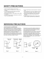
SAFETY PRECAUTIONS
1. Check if an electric leakage occurs in the set.
2. When servicing current applying parts, unplug prior to
servicing.
6. Prevent water flowing to electric elements in mechanical
parts.
3. In case of testing with power injecting, wear rubber
gloves to prevent electric shock.
7. When sloping the set, remove any materials on the set,
especially thin plate type(ex,: glass plates or books.).
4. If you use any appliances, check regular current, voltage
and capacity.
8. When servicing evaporator part, wear cotton gloves
without fail. It is to prevent wound by sharp fin of
evaporator.
5. Don't touch metal products in cold freezer room with wet
hand. It may cause frostbite.
SERVICING
AIR RECHARGING
9. Leave a breakage freezing cycle to a heavy service
center. The gas in cycle inside may soil ambient air.
PRECAUTIONS
IN COMPRESSOR
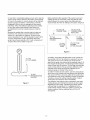
Test the refrigeration system by connecting it electrically
before refilling operation. This is necessary to ascertain the
function of the motor-compressor and identify the defects
immediately. If the defects have been found, empty the old
system of eventual R-12 residue by breaking off the end of
the extension piece at its narrow point. (Figure 1)
It is necessary to execute the soldering operation with
valve open so that the fumes caused by oil residue can
come out freely without blowholes between two tubes
during heating the point to be soldered.
The extension fitted with the male Hansen is connected to
the female fitting of the vacuum pump tube. (Figure 3)
Air evacuating from the system begins as soon as the
pump starts. The refrigeration system must be kept under
vacuum until the reading on the low-pressure gauge
indicates vacuum (0 absolute, -1 atm., -760 mm Hg) in any
case it is advisable to keep the pump running for about
30 minutes. (Figure 4)
Replace the filter and any damaged components. Unsolder
and pull off the piece remaining inside the service tube and
then attach an extension completely with male Hansen and
last, solder it to the same tube again. (Figure 2)
POINT TO BE
BROKEN
CHARGE TUBE
EXTENSION
FEMALE
HANSEN
MALE
HANSEN
SERVICE TUBE
EXTENSION
Figure 1
SOLDERING
POINT
PRESSURE
GAUGE
Figure 2
Figure 3
-3-
Figure 4
In case that a considerable leakage occurs and to stop the
vacuum pump will be necessary and add a small quantity
of Freon to the system, if vacuum should not be obtained
(pressure gauge can't fall to 1 atmosphere.), start the
refrigeration unit and find the leakage with the special
leak-finder. When the defective soldering point is visible,
re-do it after opening the extension tube valve and
reestablishing the normal outside pressure inside the
group.
Because the melted alloy is sucked into the tubes and
block them, the pressure must be rebalanced when
vacuum is in the system in soldering. As soon as the
vacuum operation is over, add the quantity in grams of R12 to the refrigeration system. Remember that every
system has an exact quantity of R-12 with a tolerance of
+5 grams than can be added. (Figure 5)
Before performing this operation (if the vacuum pump and
refilling cylinder are connected), make sure that the valve
placed between the vacuum pump and refilling tube are
closed to keep the Freon for adding to the system. (Figure 6)
_
FILLING OR
VALVE TO BE
CHARGE TUBE
REFILLING
OPENED WHEN
TO THE
REFRIGERATION
SYSTEM
TO THE
CHARGE
CYLINDER
TO THE
VACUUM
PUMP
VALVE TO BE
CLOSED
AFTER VACUUM
Figure 6
In addition, check the graduated scale on the cylinder for
the quantity of R-12 to be added, for example, if we have
750 grams of Freon in the cylinder and must add 165
grams to the group, this amount will be reached when R-12
has dropped to 585 grams, remembering that the indicator
shows a lower limit of meniscus. Do this after choosing the
scale corresponding to the gas pressure different scales
reported as the same gas pressure indicated by the
pressure gauge on the top of the column.
To make R-12 flow into the system, open the valve placed
at the base of the cylinder and connected to the filling tube.
The amount of Freon cannot be added to the system all at
once because it may cause a blocking of motor-compresson
Therefore, proceed by adding original quantity of about
20-30 grams and close the valve immediately.
The pressure rises and the motor-compressor must start,
sucking the gas and making the pressure go down again.
Regulate the valve again, maintaining the same manner
until reaching the quantity of R-12 established for the
system being charged. When the system is running, the
suction pressure must be stabilized from 0.30 to 0.6
atmosphere.
TO THE
R-12 CYLINDER
__
TO THE
=
REFRIGERATION
SYSTEM
Figure 5
-4-
AIR RECHARGING
IN COMPRESSOR
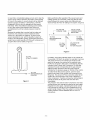
Test the refrigeration system by connecting it electrically
before refilling operation. This is necessary to ascertain the
function of the motor-compressor and identify the defects
immediately. If the defects have been found, empty the old
system of eventual R134a residue by breaking off the end
of the extension piece at its narrow point. (Figure 1)
Replace the filter and any damaged components. Unsolder
and pull off the piece remaining inside the service tube and
then attach an extension completely with male Hansen and
last, solder it to the same tube again. (Figure 2)
POINT TO BE
BROKEN
CHARGE TUBE
EXTENSION
It is necessary to execute the soldering operation with
valve open so that the fumes caused by oil residue can
come out freely without blowholes between two tubes
during heating the point to be soldered.
The extension fitted with the male Hansen is connected to
the female fitting of the vacuum pump tube. (Figure 3)
Air evacuating from the system begins as soon as the
pump starts. The refrigeration system must be kept under
vacuum until the reading on the low-pressure gauge
indicates vacuum (0 absolute, -1 atm., -760 mm Hg) in any
case it is advisable to keep the pump running for about
60 minutes. (Figure 4)
FEMALE
HANSEN
MALE
HANSEN
MP
SERVICE TUBE
EXTENSION
Figure 1
PRESSURE
GAUGE
SOLDERING
POINT
Figure 2
Figure 3
-5-
Figure 4
In case that a considerable leakage occurs and to stop the
vacuum pump will be necessary and add a small quantity
of Freon to the system, if vacuum should not be obtained
(pressure gauge can't fall to 1 atmosphere.), start the
refrigeration unit and find the leakage with the special
leak*finder. When the defective soldering point is visible,
re*do it after opening the extension tube valve and
reestablishing the normal outside pressure inside the
group.
Because the melted alloy is sucked into the tubes and
block them, the pressure must be rebalanced when
vacuum is in the system in soldering. As soon as the
vacuum operation is over, add the quantity in grams of
R134a to the refrigeration system. Remember that every
system has an exact quantity of R134a with a tolerance of
+5 grams than can be added. (Figure 5)
Before
refilling
placed
closed
performing this operation (if the vacuum pump and
cylinder are connected), make sure that the valve
between the vacuum pump and refilling tube are
to keep the Freon for adding to the system. (Figure 6)
_
FILLING OR
VALVE TO BE
CHARGE TUBE
REFILLING
OPENED WHEN
TO THE
REFRIGERATION
SYSTEM
TO THE
CHARGE
CYLINDER
TO THE
VACUUM
PUMP
VALVE TO BE
CLOSED
AFTER VACUUM
Figure 6
TO THE
R134a CYLINDER
In addition, check the graduated scale on the cylinder for
the quantity of R134a to be added, for example, if we have
750 grams of Freon in the cylinder and must add 165
grams to the group, this amount will be reached when
R134a has dropped to 585 grams, remembering that the
indicator shows a lower limit of meniscus. Do this after
choosing the scale corresponding to the gas pressure
different scales reported as the same gas pressure
indicated by the pressure gauge on the top of the column.
To make R134a flow into the system, open the valve
placed at the base of the cylinder and connected to the
filling tube. The amount of Freon cannot be added to the
system all at once because it may cause a blocking of
motor*compressor. Therefore, proceed by adding original
quantity of about 20-30 grams and close the valve
immediately.
The pressure rises and the motor*compressor must start,
sucking the gas and making the pressure go down again.
Regulate the valve again, maintaining the same manner
until reaching the quantity of R134a established for the
system being charged. When the system is running, the
suction pressure must be stabilized from 0.10 to 0.4
atmosphere.
TO THE
REFRIGERATION
SYSTEM
Figure 5
-6-
SPECIFICATIONS
ITEMS
SPECIFICATIONS
DOOR TYPE
1 DOOR
NET CAPACITY
94 l
CONDENSER
TYPE
ITEMS
INSULATION
TEMPERATURE
SYSTEM
CONTROL
DO_OR
_ CABINET
WALL CONDENSER
(FLUSH BACK)
DEFROSTING
SPECIFICATIONS
MANUAL
POLYURETHANE
POLYURETHANE
EVAPORATOR
ROLL BOND TYPE
DIMENSION
463(W)X830(H)X500(D)mm
NET WEIGHT
22 Kg
REFRIGERANT
KNOB DIAL
R-12(67g)
R-134a(60g)
VS Series
HTS-150
FREOL a 22G
COMPRESSOR
(200cc)
(200cc)
NS Series
HTS-150
FREOL a 22G
COMPRESSOR
(180cc)
(180cc)
LUBRICANT
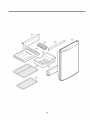
PARTS IDENTIFICATION
EVAPORATOR(Door Inside)
- The heartof the refrigerator.
- It evaporates the refrigerant
fluid and thereby absorbs
heat from the surrounding.
THERMOSTAT
Regulates the operation of
the motor and controls the
temperature inside the
refrigerator.
ICE CUBETRAY(Door Inside)
Ice cube is easy to remove
from the tray
DRIP TRAY
Catches the water that
drips off the evaporator
when defrosting.
PLASTIC COATED
SHELVES
Have full width and can
slide out.
SUPPORTER CAN
Keeps any kinds of bottles.
MAGNETIC GASKET
- Tight fitting door seal
keeps all the cooling
power locked inside,
- No hooks or latches.
PVC BAR
Keeps any kinds of fruits
and vegetables.
NOTE : This is a basic model. The shape of refrigerator is subject to change.
-7-
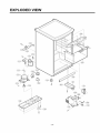
DISASSEMBLY
A. DOOR
C. COMPRESSOR
AND PTC
1. Loosen 3 screws holding an upper hinge to separate the
door body. (Figure 7)
1. Remove Clamp, Protector Cover, Power Cord and Lead
Wire first. (Figure 10)
2. Separate OLR
3. Separate PTC.
4. Remove the Compressor Base by loosening 4 bolts fixed
to base plate of the set. (Figure 11)
Figure
7
-%
B. THERMOSTAT
Figure 10
Figure 11
1. Pull Knob Dial,
2. Loosen 1 screw holding the case and pull it out to
remove the Therme cover. (Figure 8)
5. Remove the Compressor by loosening 2 earth screws
next to Compressor.
NOTE : Replace the Compressor, after peeling off
painted part of earth terminal.
• Compressor inhales the gas evaporated from Evaporator
and condenses this gas and then delivers to Condenser.
• PTC is abbreviation of Positive Temperature Coefficient
and is attatched to the Compressor, and operates motor.
• OLP prevents Motor coil from being started inside
Compressor.
• Do not turn the Adjust Screw of OLP in any way for
normal operation of OLR
Figure
8
3. Pull out thermostat in the theremostat cover, and
disconnect lead wires. (Figure 9)
NOTE : Replace a new thermostat with proper specification.
@
Figure
9
-8-
CIRCUIT DIAGRAM
THERMOS'[A'T
YL: YELLOW
4
YL
_
BK: BLACK
BK
BL: BLUE
GN{GN_L)
t
<_ BK
s_
GN:GREEN
it"__FL_REs_oR
P.T.C STARTER
THE PLUG TYPE ON CIRCUIT DIAGRAM IS SUBJECT
TO CHANGE IN DIFFERENT LOCALITIES.
J652-00041C
TROUBLESHOOTING
DEFECT
EFFECT
CAUSE
REMEDY
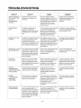
GROUP PARTIALLY
OR COMPLETELY
OUT OF
REFRIGERANT
CHARGE
Evaporatordose not frost even
though motoFcompressorruns
continually.
An empty refrigerantsystem
indicatesa leakage of R134a This
lossis generallyto be lookedfor at
the soldering pointsconnectingthe
various componentsor in an
eventualhole inthe evaporator
made by the user.
EXCESSIVELY
FULL
This defect is indicated by the
presenced water outside
refrigeratornear the motor caused
byformationsof ice on the return
tube.
If in the refrigerantsystema quantity The system mustbe emptiedand
of R134a is introducedwhich is
subsequentlyrefilled introducingthe
greater than that indicated,the
correctquantity of R134a.
excess gas dosenot terminate its
expansionin the evaporatorbut
proceedsinto the return tube.
HUMIDITY IN THE
SYSTEM
This defect is indicated by the partial
frosting of the evaporatorand by
continual defrosting cycles
determined by the interruptionof the
flow of gas on the evaporator.The
motorcompressorkeeps running.
The refrigerantsystemis humid
when there is a small percentageof
water present which, not completely
retained bythe dehydratorfilter,
enters into circulationwiththe Freon
and freezes at the capillaryexit in
the evaporator.
The system mustbe emptiedand
then refilledafter eliminatingthe
humidity.
PRESENCE OF AIR
IN THE SYSTEM
Poorperformanceof the refrigerant
systemwhich is indicated:on the
evaporatorwith a slightfrost which
dose not freezeand an excessive
overheatingof the condenserand
motor-compressor.
There is air in a refrigeratingsystem
when duringthe filling phase
vacuum is not effectedor it is not
adequately done.
Groupmust be drained and
subsequentlyrefilled after carefully
creatingvacuum.
BLOCKED
CAPILLARY
Becauseof the lack of circulation
Freonin the system,there is no
frosting of the evaporator,while a
slight overheatingof the first spiral of
the condenseris noted.
Eventualimpuritiescontained in the
Freonor in the componentsof the
refrigerationsystembefore
assembly and not retainedby the
filter can obstruct the capillary.
Torestore the systemit must be
emptied,substitutethe capillaryor
the evaporatorentirely in case the
capillaryis coaxialwith respectto
the return tube, then refill it.
MOTORCOMPRESSOR
SHORT-CIRCUITED
OR BLOCKED
The systemdose not work andthe
"clixson" intervenesinterrupting
delivery to the motorraompressor.
In case of short circuit, the
breakdownis dueto the electric
winding: if blocked,thereis a
mechanicalfailure in the motor-
The motor-compressormustbe
replacedand then proceedwith
refilling.
Leakagemust be eliminated by
resolderingthe defectivepoint or
substitutingthe damaged
evaporator.
compressoE
MOTORCOMPRESSOR
DOSE NOT
COMPRESS
Nofrost forms on the evaporator
even if the motor-compressoris
apparentlyrunning regulary.
In this case there is a mechanical
failure in the diaphramvalveswhich:
remainingcontinuallyopen, do not
permitthe pistonto suck and
compressor the which
consequenteIydose not circulatein
the system.
The motor-comprossormustbe
replacedand then proceedwith
refilling.
NOISY MOTORCOMPRESSOR
In case of mechanicalfailure in the
motor-compressorthere in an
excessive noise when the system is
functioning: in case a suspension
spring is unhooked,bangingwill be
heardand therewill be especially
strong vibrationswhen the system
starts up and stops,
The causeof the excessivenoise is
normailyto be sought for in a
mechanicalbreak down,and only
rarely in the unhookingof one of the
suspensionsprings.
The motor-comprossormustbe
substitutedand then proceedwith
the refilling.
-10-
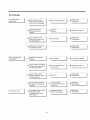
NO COOLING
The Compressor
doesn't run,
Check if the current
flows at the contacting
Poor contacting point
Check if the current flows
at the contacting point of
the starting system.
Poor contacting point
and broken
Check
if the current
flowing of the sub coil of
_
-11-
"
Replace the
Thermostat.
Replace the device.
COMPRESSOR
AND ANOTHER
ELECTRIC
COMPONENTS
Separate the PTC-STARTER from
the Compressor and measure the
voltage between M and C of the
Compressor.
Check the
L
Equal to the applied
_
voltage. (Rating
_
voltage + 10%)
I
r_
2>
YES
resistance of the
Compressor Motor.
YES
NO
YES
OLP works within 30 sec.
in forcible OLP operation
by turning instant power on
NO
Measure minimum starting voltage
after checking steps 1-3 above.
And measure the pressure balance
of the PTC with the interval of
more than 5 min.
-12-
_
NO
_
Replace OLR
PTC
Poor starting or no
operating of the
Compressor.
First, separate the PTC from
the Compressor and check the
4D voltage between NO 5 and 6
in the PTC with a muititester or
Wheatstone
Bridge.
F
Normal
_
Check another
electric
components.
__
Abnormal
_
PTC.
Replace the
_{_
Abnormal
_
PTC.
Replace the
Separate the OLP from
the Compressor and
4m check resistance value
between two terminals of
OLP with Tester.
-13-
EXPLODED
VIEW
-14-
-15-
HOME
DEPOT(HDP)
Electrical
ITEM
Specification
GR-051SF
GR-131SF
GR=151SF
GR_051SF
GR_131SPF
GR-151SPF
70+15%
70+15%
70+15%
ENERGY CONSUMPTION(kwh/yr)
288
330
350
AMPERE(Amp)
0.84
1.0
0.7
RATING(V/Hz)
115/60
115/60
115/60
REFRIGERANT
R134a
R134a
R134a
1.41
2.12
3.35
COMPRESSOR
NS24LBCM
NS24LBCG
NS30LACM
OLP
4TM232NFB
4TM232NFB
4TM265MFB
PTC
P6R8MD
P6R8MC
P6R8MD
BUYER MODEL NAME
RATED INPUT(W)
DEFROST INPUT(W)
CHARGE(Oz)
CAPACITOR-R
CAPACITOR-S
101JF/250VAC
101JF/250VAC