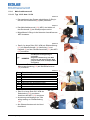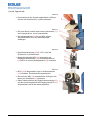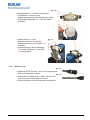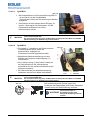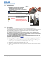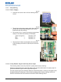
1
Bedienungsanleitung
Instruction Manual
Chlordioxid (ClO2) Dosierstation
Chlorine dioxide (ClO2) Metering Station
16 l/h
54 l/h
210 l/h
417101376_ClO2_Dosierstationen.doc
Rev. 1-12.07
Inhaltsverzeichnis
1
Allgemeines ....................................................................................................................4
1.1
1.2
1.3
Normen ....................................................................................................................................... 4
Gewährleistungsumfang............................................................................................................... 4
Kontaktadresse / Hersteller: ......................................................................................................... 4
2
Sicherheit .......................................................................................................................5
2.1
2.2
2.3
2.4
Sicherheitshinweise ..................................................................................................................... 5
Hervorhebungen .......................................................................................................................... 5
Spezielle Sicherheitshinweise bei Wartungs- und Reparaturarbeiten .............................................. 5
Umgang mit wässrigen Chlordioxid-Lösungen ............................................................................... 5
2.4.1
2.4.1.1
2.4.1.2
2.4.1.3
2.4.2
2.4.2.1
2.4.2.2
2.4.3
2.4.4
Allgemeiner Umgang ....................................................................................................................................
Lagerung .....................................................................................................................................................
Maßnahmen bei Verschütten, Auslaufen, Gasaustritt und Entsorgung ............................................................
Maßnahmen bei Bränden .............................................................................................................................
Gesundheitsschutz ......................................................................................................................................
MAK-Wert Chlordioxidgas ............................................................................................................................
Persönliche Schutzausrüstung......................................................................................................................
Gesundheitsgefahren ...................................................................................................................................
Erste Hilfe ...................................................................................................................................................
3
4
Lieferumfang ..................................................................................................................7
Gerätebeschreibung .......................................................................................................9
4.1
4.2
4.3
4.4
4.5
Ausführung 16 l/h ........................................................................................................................ 9
Ausführung 54 l/h ........................................................................................................................ 9
Ausführung 210 l/h ...................................................................................................................... 9
Geräteaufbau ............................................................................................................................ 10
Bedien- und Anzeigeelemente .................................................................................................... 10
5
Montage / Installation ...................................................................................................11
5
5
5
6
6
6
6
6
6
5.1
Installation ................................................................................................................................ 11
5.1.1
5.1.2
5.1.3
5.1.3.1
5.1.3.2
5.1.4
5.1.4.1
5.1.4.2
5.1.5
5.1.6
5.1.6.1
5.1.6.2
5.1.7
5.1.8
5.1.9
5.1.10
5.1.10.1
5.1.10.2
5.1.10.3
5.1.10.4
5.1.10.5
5.1.10.6
Auffangwanne.............................................................................................................................................11
Pumpe .......................................................................................................................................................12
Saugleitung ................................................................................................................................................12
Typ 16 l/h bzw. 54 l/h ..................................................................................................................................12
Typ 210 l/h .................................................................................................................................................13
Mehrfunktionsventil .....................................................................................................................................14
Typ 16 l/h bzw. 54 l/h ..................................................................................................................................14
Typ 210 l/h .................................................................................................................................................15
Dosierventil ................................................................................................................................................16
Verdrahtung der Pumpe ..............................................................................................................................17
Spannungsversorgung ................................................................................................................................17
Freigabesignal (Pump Enable) und Impulseingang der Pumpe ......................................................................17
Aktivkohlefilter ............................................................................................................................................19
Niveaugeber ...............................................................................................................................................19
Leckageschalter .........................................................................................................................................20
Externe elektrische Anschlüsse ...................................................................................................................21
Externe Spannungsversorgung ....................................................................................................................22
Produktionsfreigabe für die Halox ClO 2 -Erzeugungsanlage ...........................................................................22
Wasserzählereingang / -ausgänge ...............................................................................................................22
Externes Freigabesignal (optional) ..............................................................................................................22
Alarmausgang (optional) .............................................................................................................................22
PL U S
) (optional) .............................................................23
Dosiermengenüberwachung mit Ovalradzähler (OGM
6
Inbetriebnahme .............................................................................................................24
6.1
6.2
6.3
Halox ClO 2 -Erzeugungsanlage ................................................................................................... 24
ClO 2 -Dosierstation ..................................................................................................................... 24
Erstbefüllung ............................................................................................................................. 24
7
Betrieb der ClO 2 -Dosierstation .....................................................................................25
7.1
Betriebszustände, Schaltausgänge und Alarm............................................................................. 25
8
Wartung ........................................................................................................................26
8.1
Verschleißteile .......................................................................................................................... 26
8.1.1
8.1.2
Typ 16 l/h / 54 l/h........................................................................................................................................26
Typ 210 l/h .................................................................................................................................................26
8.2
Ersatzteile................................................................................................................................. 27
9
10
Fehler-, Alarm- und Statusmeldungen .........................................................................28
Zubehör ........................................................................................................................29
10.1
10.2
10.3
Photometer zur Schnellbestimmung von Chlordioxid ................................................................... 29
Kontaktwassermesser / Magnetisch Induktiver Durchflussmesser ................................................ 29
Statischer Mischer ..................................................................................................................... 29
11
12
Technische Daten .........................................................................................................30
Konformitätserklärung .................................................................................................31
417101376_ClO2_Dosierstationen.doc
-2-
Rev. 1-12.07
Table of contents
1
General Points ..............................................................................................................32
1.1
1.2
1.3
Standards ................................................................................................................................. 32
Extent of Warranty..................................................................................................................... 32
Contact Address/Manufacturer: .................................................................................................. 32
2
Safety ............................................................................................................................33
2.1
2.2
2.3
2.4
Safety Information ..................................................................................................................... 33
Emphases ................................................................................................................................. 33
Special Safety Instructions for Maintenance and Repair Work...................................................... 33
Handling Aqueous Chlorine Dioxide Solutions ............................................................................. 33
2.4.1
2.4.1.1
2.4.1.2
2.4.1.3
2.4.2
2.4.2.1
2.4.2.2
2.4.3
2.4.4
General Handling Instructions .....................................................................................................................33
Storage ......................................................................................................................................................33
Spillage, Leakage, Gas Escape, and Disposal ..............................................................................................33
Fire ............................................................................................................................................................34
Health Protection ........................................................................................................................................34
MAC Value of Chlorine Dioxide Gas.............................................................................................................34
Personal Protective Equipment ....................................................................................................................34
Health Risks ...............................................................................................................................................34
First Aid .....................................................................................................................................................34
3
4
Scope of Supply ...........................................................................................................35
Unit Description............................................................................................................37
4.1
4.2
4.3
4.4
4.5
16 l/h Design ............................................................................................................................. 37
54 l/h Design ............................................................................................................................. 37
210 l/h Design ........................................................................................................................... 37
Unit Design ............................................................................................................................... 38
Control and Display Elements .................................................................................................... 38
5
Assembly/Installation ...................................................................................................39
5.1
Installation ................................................................................................................................ 39
5.1.1
5.1.2
5.1.3
5.1.3.1
5.1.3.2
5.1.4
5.1.4.1
5.1.4.2
5.1.5
5.1.6
5.1.6.1
5.1.6.2
5.1.7
5.1.8
5.1.9
5.1.10
5.1.10.1
5.1.10.2
5.1.10.3
5.1.10.4
5.1.10.5
5.1.10.6
Collecting Tray ...........................................................................................................................................39
Pump .........................................................................................................................................................40
Suction Line ...............................................................................................................................................40
16l/h and 54l/h Types..................................................................................................................................40
210 l/h Type ...............................................................................................................................................41
Multi-Function Valve ...................................................................................................................................42
16l/h and 54l/h Types..................................................................................................................................42
210 l/h Type ...............................................................................................................................................43
Metering Valve ...........................................................................................................................................44
Pump Wiring ...............................................................................................................................................45
Power Supply .............................................................................................................................................45
‘Pump Enable’ Signal and Pump Pulse Input ................................................................................................45
Active Carbon Filter ....................................................................................................................................47
Level Sensor ..............................................................................................................................................47
Leakage Switch ..........................................................................................................................................48
External Electrical Connections ...................................................................................................................49
External Power Supply ................................................................................................................................50
Product Release for Halox ClO 2 Generator ...................................................................................................50
Water Meter Inputs/Outputs.........................................................................................................................50
External Enable Signal (Optional) ................................................................................................................50
Alarm Output (Optional) ..............................................................................................................................50
P L US
) (Optional) .....................................................51
Metering Quantity Monitoring with Oval Gear Meter (OGM
6
Startup ..........................................................................................................................52
6.1
6.2
6.3
Halox ClO 2 Generator ................................................................................................................ 52
ClO 2 Metering Station ................................................................................................................ 52
First Filling ................................................................................................................................ 52
7
Operating the ClO 2 Metering Station ............................................................................53
7.1
Operating States, Relay Outputs, and Alarm ............................................................................... 53
8
Maintenance .................................................................................................................55
8.1
Wearing Parts ........................................................................................................................... 55
8.1.1
8.1.2
16l/h and 54l/h Types..................................................................................................................................55
210 l/h Type ...............................................................................................................................................55
8.2
Spare Parts ............................................................................................................................... 56
9
10
Error, Alarm, and Status Notifications .........................................................................57
Accessories ..................................................................................................................58
10.1
10.2
10.3
Photometer for Quick Measurement of Chlorine Dioxide .............................................................. 58
Contact Water Meter/Magnetic-Inductive Flow Meter ................................................................... 58
Static Mixer ............................................................................................................................... 58
11
12
Technical Data ..............................................................................................................59
Conformity Declaration ................................................................................................60
417101376_ClO2_Dosierstationen.doc
-3-
Rev. 1-12.07
1
Allgemeines
Dieses Technische Handbuch enthält alle Anweisungen zur Installation, Inbetriebnahme,
Wartung und Reparatur der ClO2-Dosierstationen.
Die Sicherheitshinweise und Hervorhebungen sind in jedem Fall zu beachten!
1.1
Normen
Die ClO2-Dosiersstationen halten die geforderten Schutzziele ein.
Zur Beurteilung wurden folgende europäische Normen angewendet:
•
•
•
•
•
•
1.2
EN 61000-6-2
EN 61000-6-4
EN 60335-1
EN 12100-1
EN 12100-2
DIN EN 809
Gewährleistungsumfang
Gewährleistung in Bezug auf Betriebssicherheit, Zuverlässigkeit und Leistung der ClO2Dosierstationen wird vom Hersteller nur unter folgenden Bedingungen übernommen:
• Montage, Anschluss, Einstellung, Wartung und Reparatur werden von autorisiertem und
geschultem Fachpersonal durchgeführt.
• Die ClO2-Dosierstation wird entsprechend den Ausführungen der im Lieferumfang
enthaltenen Bedienungsanleitungen verwendet.
• Bei Reparaturen dürfen nur Original-Ersatzteile verwendet werden.
Im Übrigen gelten die allgemeinen Garantie- und Leistungsbedingungen der
Fa. ECOLAB Engineering GmbH.
1.3
Kontaktadresse / Hersteller:
ECOLAB Engineering GmbH
Raiffeisenstraße 7
D-83309 Siegsdorf
Telefon (+49) 86 62 / 61 0
Telefax (+49) 86 62 / 61 2 35
eMail: [email protected]
417101376_ClO2_Dosierstationen.doc
-4-
Rev. 1-12.07
2
Sicherheit
2.1
Sicherheitshinweise
• Die Anschluss- und Reparaturarbeiten an der ClO2-Dosierstation dürfen nur von
autorisiertem Fachpersonal ausgeführt werden.
• Vor allen Arbeiten an elektrischen Teilen unbedingt vom Netz trennen.
• Bei Wartungs- und Reparaturarbeiten ist geeignete Schutzkleidung zu tragen.
• Die Sicherheitsbestimmungen im Umgang mit Chemikalien sind stets zu beachten.
2.2
Hervorhebungen
In dieser Bedienungsanleitung haben die Hervorhebungen VORSICHT, ACHTUNG,
WICHTIG und HINWEIS folgende Bedeutung:
wird benutzt, wenn ungenaues Befolgen oder Nichtbefolgen von Bedienungsanweisungen,
VORSICHT Arbeitsanweisungen, vorgeschriebenen Arbeitsabläufen und dergleichen zu Verletzungen
oder Unfällen führen kann.
*
)
2.3
ACHTUNG
wird benutzt, wenn ungenaues Befolgen oder Nichtbefolgen von Bedienungsanweisungen,
Arbeitsanweisungen, vorgeschriebenen Arbeitsabläufen und dergleichen zur Beschädigung
des Gerätes führen kann.
WICHTIG
wird benutzt, wenn auf eine besondere Aufmerksamkeit im Umgang mit dem Gerät geachtet
werden muss.
HINWEIS
wird benutzt, wenn auf eine Besonderheit aufmerksam gemacht werden soll.
Spezielle Sicherheitshinweise bei Wartungs- und Reparaturarbeiten
VORSICHT
*
WICHTIG
Reparaturarbeiten dürfen nur bei gezogenem Netzstecker, bzw. in spannungslosem Zustand
vorgenommen werden.
Bei Wartungs- und Reparaturarbeiten an Teilen, die mit gefährlichen Produkten in
Berührung kommen, sowie bei Gebindewechsel ist wegen der Verätzungs-gefahr die
vorgeschriebene Schutzkleidung (Schutzbrille, Schutzhandschuhe, Schürze) zu tragen.
Bei Reparaturen dürfen nur Original-Ersatzteile verwendet werden.
2.4
Umgang mit wässrigen Chlordioxid-Lösungen
2.4.1
Allgemeiner Umgang
2.4.1.1 Lagerung
Chlordioxid kann wegen seiner Explosionsgefährlichkeit weder als Gas noch als konzentrierte
wässrige Lösung über einen längeren Zeitraum gelagert werden. Es wird daher nur als
verdünnte wässrige Lösung in speziellen Chlordioxid-Erzeugungsanlagen für die sofortige
Verwendung erzeugt.
2.4.1.2 Maßnahmen bei Verschütten, Auslaufen, Gasaustritt und Entsorgung
Ausgetretenes Gas mit Sprühwasser niederschlagen.
Ausgelaufene Lösung mit Natriumthiosulfat-Lösung übergießen, dann mit viel Wasser
verdünnen und in die Kanalisation wegspülen.
417101376_ClO2_Dosierstationen.doc
-5-
Rev. 1-12.07
2.4.1.3 Maßnahmen bei Bränden
Chlordioxid selbst ist nicht brennbar, wirkt aber brandfördernd. Explosionsartige Zersetzung
bei Temperaturen ab 100°C. Behälter mit Wasser kühlen, ausgetretenes Chlordioxid-Gas mit
Sprühwasser niederschlagen.
Es gibt keine Einschränkung für Feuerlöschmittel bei Umgebungsbränden.
2.4.2
Gesundheitsschutz
2.4.2.1 MAK-Wert Chlordioxidgas
MAK-Wert:
0,1 ppm (ml/m³) bzw. 0,3 mg/m³
2.4.2.2 Persönliche Schutzausrüstung
Atemschutz:
2.4.3
Atemschutzmaske, Filter B/grau
Augenschutz:
Schutzbrille, Gesichtsschutz
Handschutz:
Gummihandschuhe
Andere:
Schutzkleidung
Gesundheitsgefahren
Eine Chlordioxid-Gaskonzentration über 45 mg ClO2 / m³ bereitet Atembeschwerden und
führt zu Reizungen der Schleimhäute und Kopfschmerzen.
Allgemein ruft Chlordioxid starke Reizerscheinungen im Bereich der Schleimhäute von Augen
und Atemorganen hervor.
2.4.4
Erste Hilfe
Mit Chlordioxid oder seiner wässrigen Lösung in Kontakt gekommene Kleidung sofort
entfernen, Haut mit Seife und viel Wasser gründlich waschen.
Spritzer in die Augen mehrere Minuten unter fließendem Wasser bei gut geöffnetem Lidspalt
ausspülen.
Nach Einatmen von Chlordioxid Î Frischluft, absolute Ruhigstellung, Horizontallagerung,
Wärmeschutz.
Umgehend Arzt verständigen, auch wenn nicht sofort Beschwerden auftreten. ggf. schneller
schonender Transport ins Krankenhaus.
417101376_ClO2_Dosierstationen.doc
-6-
Rev. 1-12.07
3
Lieferumfang
Bezeichnung
Darstellung
Typ 16 l/h
Typ 54 l/h
Typ 210 l/h
Behälter
Im Auslieferungszustand am Behälter verbaut
34124005
Steuerung
(Metering Station Control)
283160
Schwimmerschalter
für Leckagemeldung
288521
Eingangsverschraubung
3/8 Zoll
415101969
Eingangsverschraubung
½ Zoll
Sauganschluss mit Saugleitung
und Bodensaugventil
Rückführungsanschluss
415102359
-
283162 (DK)
283163 (DK)
283164 (DK)
-
38316101
415101980
283167 (DK)
Membrandosierpumpe
Typ EMP III, 16 l/h, E60 PVDF/FPM
149561
Membrandosierpumpe
Typ EMP III, 54 l/h, E60 PVDF/FPM
149761
Membrandosierpumpe
Typ EMP IV, 210 l/h, E60 PVDF/FPM
Pumpenbefestigung
150161
Schrauben M 5 x 20 (4 Stück)
Schrauben M 5 x 25 (4 Stück)
Scheiben (4 Stück)
413031022
413031023
413501720
Mehrfunktionsventil
MFV II-III
249243
Mehrfunktionsventil
MFV III-IV
417101376_ClO2_Dosierstationen.doc
250064
-7-
Rev. 1-12.07
Bezeichnung
Darstellung
Typ 16 l/h
Typ 54 l/h
Typ 210 l/h
Montagewinkel für MFV
38316202
Schraube M8x16 (2 Stück)
413031054
Niveaugeber
418264038
Kabelbinder
417806041
Aktivkohlefilter
415730060
10 m Dosierrohr
(6/8, PTFE)
10 m Dosierrohr
(12/16, PTFE)
417400224
417400259
Dosierventil
1/2 Zoll
245037
Dosierventil
3/4 Zoll
283169
Auffangwanne
419800478
Doppelverschraubung 1 ¼
283165 (DK)
Pumpenanschluss
250076
Bedienungsanleitung
417101376
417101376_ClO2_Dosierstationen.doc
-8-
Rev. 1-12.07
4
Gerätebeschreibung
Die ClO2 Dosierstationen wurden speziell für die Förderung von Chlordioxid-Lösung,
produziert aus den Halox Generatoren H1000SRE (Typ 16 l/h und 54 l/h) sowie
H2000SRE ausgelegt.
Der Grundaufbau beinhaltet einen speziell beschichteten Tank, Nieveauüberwachung mit
Alarmmeldungen, eine Auffangwanne mit Leckagemeldung sowie einen Klemmenkasten mit
integrierter Steuerung (Metering Station Control).
Alle Komponenten und Materialien wurden in Bezug auf Sicherheit und chemische
Beständigkeit sorgfältig ausgewählt. Robuste und betriebssichere EMP – Pumpen
entsprechen in Ihrer Dosierleistung den Erzeugungsraten der Halox Anlagen.
Dieses technische Handbuch beinhaltet die Typen 16 l/h, 54 l/h und 210 l/h.
4.1
Ausführung 16 l/h
Typ 16 fördert pro Stunde bis zu 16 Liter (19 Liter) ClO2 -Lösung in druckbeaufschlagte
(bis 10 bar*) Leitungsströme mit einer Pumpe der Bauart EMP III. 19 l/h Lösung ist die
Ausstoßleistung einer Halox H1000 oder H1000SRE mit zwei Kassetten.
4.2
Ausführung 54 l/h
Typ 54 fördert pro Stunde bis zu 54 Liter (64 Liter) ClO2 -Lösung in druckbeaufschlagte
(bis 10 bar*) Leitungsströme mit einer Pumpe der Bauart EMP III. 38 l/h Lösung ist die
Ausstoßleistung einer Halox H1000 oder H1000SRE mit vier Kassetten.
4.3
Ausführung 210 l/h
Typ 210 fördert pro Stunde bis zu 210 Liter (252 Liter) ClO2 -Lösung in druckbeaufschlagte
(bis 10 bar*) Leitungsströme mit einer Pumpe der Bauart EMP IV. 246 l/h Lösung ist die Ausstoßleistung einer Halox H2000 oder H2000SRE mit vier Kassetten.
* Höhere Förderleistungen sind möglich bei geringeren Gegendrücken. Aktuelle Durchsatzdaten können den
Leistungskurven der EMP Pumpen in der Bedienungsanleitung entnommen werden.
)
VORSICHT
Für den Umgang mit Chlordioxid-Lösungen müssen die speziell gültigen Unfallverhütungsvorschriften beachtet werden.
Alle Personen die mit den ClO2-Erzeugungs- und -Dosieranlagen in Berührung kommen
können, müssen an einer entsprechenden Sicherheitsbelehrung teilgenommen haben.
HINWEIS
Die Bedienungsanleitungen der EMP-Dosierpumpen sind als CD im Lieferumfang
enthalten. Ebenso enthalten ist die Bedienungsanleitung für das Mehrfunktionsventil.
Für den einwandfreien Betrieb der Geräte sind alle Anweisungen, Sicherheitsvorkehrungen
und Wartungsvorgaben zu befolgen.
417101376_ClO2_Dosierstationen.doc
-9-
Rev. 1-12.07
4.4
Geräteaufbau
Abb. 4.1
Abb. 4.2
Abb. 4.3
Typ 16 und 54 l/h
4.5
Typ 210 l/h
Bedien- und Anzeigeelemente
Abb. 4.4
417101376_ClO2_Dosierstationen.doc
Pos.
1
2
3
4
5
6
- 10 -
Bezeichnung
LED
Überfüllalarm
Rot
Standby
Orange
Refill
Orange
Leermeldung
Rot
Alarm
Rot
Quit-Taste
Durch Drücken der Quit-Taste wird der
Summer und der ext. Alarm quittiert.
Die Alarm-LED schaltet von Blink- in
Dauerlicht.
Rev. 1-12.07
5
Montage / Installation
5.1
Installation
Nach dem Auspacken Vollständigkeit und Unversehrtheit des Materials überprüfen.
5.1.1
Auffangwanne
Die ClO2-Dosierstation sollte zusammen mit der HALOX ClO2-Erzeugungsanlage auf die
Auffangwanne gestellt werden.
Abb. 5.1
Abb. 5.2
Typ 16 und 54 l/h
Pos.
1
2
3
4
Bezeichnung
Leckageschalter
Gewindeeinsätze für EMP III
Adapterplatte für EMP IV
Steuerung Metering Station Control
Typ 210 l/h
Pos.
5
6
7
8
Bezeichnung
Leitung für Pumpenfreigabe „Pump Enable“
Rücklauf vom Mehrfunktionsventil MFV
Anschlussverschraubung für Produktleitung aus
der Halox ClO2-Erzeugungsanlage
Leitung für Produktionsfreigabe Halox ClO2Erzeugungsanlage
Der Aufstellungsort muss folgende Eigenschaften beinhalten:
•
•
•
•
•
)
Möglichst nahe zur Dosierstelle
Auffangwanne muss auf ebenem Untergrund stehen
Raum ohne direkte Sonneneinstrahlung, frostsicher und belüftbar.
Umgebungstemperatur maximal 40°C
Bodenablauf und Spülwasser zur gefahrlosen Entfernung von übergelaufenen Produkten
HINWEIS
Am Aufstellungsort dürfen keine Geräte oder Aggregate betrieben werden, die geeignet
sind EMV-Störungen hervorzurufen (z.B durch Mobilfunkgeräte, Hochspannungsrelais).
417101376_ClO2_Dosierstationen.doc
- 11 -
Rev. 1-12.07
5.1.2
Pumpe
Abb. 5.3
• Pumpe aus der Originalverpackung entnehmen
und auf den Sockel des Behälters stellen.
• Montagelöcher der Pumpengrundplatte auf die
Gewindeeinsätze des Sockels (bei Typ 210 l/h auf
die Gewinde der Zwischenplatte) ausrichten und
mittels mitgelieferter Schrauben (M5 x 25) und
Beilagscheiben montieren.
)
HINWEIS
Schrauben nicht mit Gewalt
anziehen!
(Bild zeigt Version EMP III)
Abb. 5.4
ACHTUNG
Bei TYP 210 l/h die Schrauben
noch nicht festziehen, da zuvor die
Saugleitung ausgerichtet werden
muss! (siehe 5.1.4.2 Typ 210 l/h)
• Gelbe Abdeckkappen (1) von Saug- und
Druckventil entfernen.
5.1.3
Saugleitung
5.1.3.1 Typ 16 l/h bzw. 54 l/h
Abb. 5.5
Pos. Bezeichnung
1
2
3
4
5
Saugventil
Kegelteil
Klemmring
Überwurfmutter
Klemmverschraubung
• Mitgelieferten O-Ring der Pumpe in die Nut am
Saugventil (1, unten) einsetzen.
• Überwurfmutter (4), Klemmring (3) und Kegelteil (2)
wie in Abbildung 5.5 auf der Saugleitung anordnen.
417101376_ClO2_Dosierstationen.doc
- 12 -
Rev. 1-12.07
Abb. 5.6
• Saugrohr (6) möglichst bis Anschlag auf das
Kegelteil schieben.
• Saugrohr (6) mit dem Klemmring auf dem Kegelteil
festklemmen. Unterhalb des Klemmrings sollten
noch mindestens 1-2 mm Rohr sichtbar sein.
• Untere Klemmverschraubung (5) lockern und das
Saugrohr (6) so weit nachziehen bis das Kegelteil
plan auf das Saugventil (1) aufgesetzt werden
kann.
• Überwurfmutter (4) mit der Hand fest auf das
Saugventil (1) aufschrauben.
Abb. 5.7
• Die untere Klemmverschraubung (5) wieder
festziehen um das Saugrohr (6) zum Behälter hin
abzudichten.
Pos.
6
Bezeichnung
Saugrohr
5.1.3.2 Typ 210 l/h
Abb. 5.8
• Einen der mit der Pumpe mitgelieferten O-Ringe in
die Nut am Saugventil (1, unten) einsetzen.
• Saugventil (1) der Pumpe und Einlegteil (8) der
Saugleitung aufeinander ausrichten. Über den
Dichtring (9) der Behälterverschraubung kann die
Höhe ausgeglichen werden.
• Überwurfmutter (4) handfest verschrauben.
Pos.
7
8
Bezeichnung
Dichtring
Einlegteil
Abb. 5.9
• Anschließend die Befestigungsschrauben der
Pumpe festziehen.
)
HINWEIS
Schrauben nicht mit Gewalt anziehen!
417101376_ClO2_Dosierstationen.doc
- 13 -
Rev. 1-12.07
5.1.4
Mehrfunktionsventil
5.1.4.1 Typ 16 l/h bzw. 54 l/h
Abb. 5.10
• Den zweiten mit der Pumpe mitgelieferten O-Ring in
die Nut des Druckventils (9) (oben) einsetzen.
Abb. 5.11
• Das Mehrfunktionsventil (10) (MFV) wird direkt auf
das Druckventil (9) der Dosierpumpe montiert.
• Mitgelieferte O-Ringe in die Nuten der Anschlüsse am
MFV einsetzen.
Abb. 5.12
• Das 0,6 m lange Rohr (ID6 / AD8) als Rücklaufleitung
(13) mit Überwurfmutter (4), Klemmring (3) und
Kegelteil (2) auf den Rücklaufanschluss (11) des MFV
(10) montieren.
)
HINWEIS
Es sind die entsprechenden Teile aus
dem Beipack der Saugleitung zu
verwenden.
(Kegelteil und Klemmring vom MFV
sind nur für PVC Schlauch ID6 / AD12
geeignet. Nicht Teile aus Beipack MFV
verwenden!)
• Das andere Ende der Rücklaufleitung (13) mit der
Klemmverschraubung (12) am Behälteranschluss
(14) montieren.
Abb. 5.13
Pos.
2
3
4
10
11
12
13
14
15
Bezeichnung
Kegelteil
Klemmring
Überwurfmutter Behälteranschluss
MFV
Rücklaufanschluss MFV
Überwurfmutter Rücklaufanschluss
Rücklaufleitung
Behälteranschluss
Dosierleitung
• Das 10 m lange Rohr ID6 / AD8 als
Dosierleitung (15) am oberen
Anschluss des MFV (10) montieren.
Abb. 5.14
Abb. 5.15
• Anordnung und Montage der Teile
erfolgt analog zur Rücklaufleitung
(13).
• Alle Überwurfmuttern mit der Hand
festziehen!
417101376_ClO2_Dosierstationen.doc
- 14 -
Rev. 1-12.07
5.1.4.2 Typ 210 l/h
Abb. 5.16
• Den zweiten mit der Pumpe mitgelieferten O-Ring in
die Nut des Druckventils (9) (oben) einsetzen.
Abb. 5.17
• Die zwei oberen und die zwei unteren Schrauben (17)
am Pumpenkopf ca. 4 mm herausdrehen.
• Den Montagewinkel (16) für das MFV mit den
Schlüssellöchern über die Schraubenköpfe
einhängen.
Abb. 5.18
• Doppelverschraubung (20) (2 x G1¼) auf das
Druckventil (9) aufschrauben.
• Mehrfunktionsventil MFV (10) auspacken und
beigelegte Rohrschellen (18) mit Imbusschrauben
(19) M8 x 16 auf den Montagewinkel (16) montieren.
Abb. 5.19
• MFV (10) in dargestellter Lage in die Rohrschellen
(18) einrasten. Durchflussrichtung beachten!
• Die drei beim MFV (10) mitgelieferten O-Ringe in die
Nuten der Anschlüsse (21) einsetzen.
• Obere Überwurfmutter der Doppelverschraubung (20)
auf das Anschlussgewinde am Eingang des MFV (10)
aufschrauben und mit der Hand festziehen.
417101376_ClO2_Dosierstationen.doc
- 15 -
Rev. 1-12.07
Abb. 5.20
• Montagewinkel (16) auf dem Pumpenkopf
nachjustieren, so dass auf die
Doppelverschraubung keine Spannungen wirken.
• Pumpenkopf-Schrauben (17) mit 8 Nm wieder
festziehen.
• Überwurfmutter (24) des
Winkelanschlusses (25) auf den
Rücklaufanschluss (23) des MFV (10)
montieren.
Abb. 5.21
Abb. 5.22
• Verschraubung für die Dosierleitung
(22) auf den Ausgang (26) des MFV
(10) aufschrauben.
5.1.5
Dosierventil
Abb. 5.23
• Dosierrohr PTFE, 6/8 bzw. 12,2/16 vom Ausgang des
MFV zur Dosierstelle verlegen.
Abb. 5.24
• Dosierventil mit Gewinde G½“ (Abb.5.23) bzw. G¾“
(Abb.5.24) an der Dosierstelle montieren.
• Dosierrohr kürzen und am Dosierventil anschließen.
417101376_ClO2_Dosierstationen.doc
- 16 -
Rev. 1-12.07
5.1.6
Verdrahtung der Pumpe
5.1.6.1 Spannungsversorgung
Abb.5.25
•
Deckel der Steuerung (Metering Station Control)
aufschrauben und abnehmen.
•
Das Netzanschlusskabel aus der Pumpe durch die
passende Kabelverschraubung auf der Unterseite in
das Gehäuse führen.
•
Schraubsteckklemme X2 (4, 5 und 6) abziehen und
Aderendhülsen wie dargestellt anklemmen.
Abb.5.26
gelb / grün
blau
schwarz
->
->
->
Klemme 4, PE
Klemme 5, N
Klemme 6, L1
Abb. 5.27
•
Klemme X2 wieder aufstecken und zur
Zugentlastung und Abdichtung die
Überwurfmutter der Klemmverschraubung
festziehen.
5.1.6.2 Freigabesignal (Pump Enable) und Impulseingang der Pumpe
Die Metering Station Control ist für eine mengenproportionale Dosierung der Pumpe
vorbereitet.
Impulse eines angeschlossenen Wasserzählers werden über das Freigabekabel auf den
Pumpeneingang für Impuls- / Normsignal und Dosiersperre durchgeschaltet.
Für andere Ansteuerungsarten (z.B. messwertabhängig oder manuell) müssen die Signale,
entsprechend der Bedienungsanleitung für E60-Dosierpumpen, direkt auf die Pumpe
gegeben werden oder die interne Betriebsart (Werkseinstellung) gewählt werden.
417101376_ClO2_Dosierstationen.doc
- 17 -
Rev. 1-12.07
5.1.6.2.1
Typ EMP III
Abb. 5.28
• Bei Dosierstationen mit Pumpenausführung EMP III
(16 und 54 l/h) ist das Freigabekabel
(„Pump Enable“-Kabel) aus der Steuerung mit Stecker
ausgeführt.
•
*
Den Stecker auf den rechten oberen Eingang, für
Impuls- / Normsignal und Dosiersperre, auf der
Pumpenfront aufstecken und mit der
Überwurfmutter sichern.
WICHTIG
5.1.6.2.2
Bei E60-Ausführungen muss die Dosiersperre in der Konfiguration aktiviert werden
(siehe Handbuch EMP E60).
Für die Impulsansteuerung muss die Betriebsart der Pumpe über das Menü von INTERN
(Werkseinstellung) auf EXTERN umgeschaltet werden.
Typ EMP IV
• Frontplatte (27) abnehmen und Platine aus dem
Pumpengehäuse ziehen, damit der
Klemmenraum zugänglich ist.
Die Klemmen können abgesteckt werden.
Abb. 5.29
• Mitgelieferte Kabelverschraubung aus dem
Beipack der Pumpe am Impulseingang (28)
einschrauben.
• Die 3-adrige Leitung („Pump Enable“-Kabel) aus
der Steuerung durch die Verschraubung
durchführen und wie rechts beschrieben auf die
Klemmen montieren.
• Die Überwurfmutter der Kabelverschraubung
festziehen und die Front wieder verschließen.
*
WICHTIG
weiß
schwarz
blau
->
->
->
Klemme 6
Klemme 7
Klemme 8
Bei E60-Ausführungen muss die Dosiersperre in der Konfiguration aktiviert werden
(siehe Handbuch EMP E60).
Für die Impulsansteuerung muss die Betriebsart der Pumpe über das Menü von INTERN
(Werkseinstellung) auf EXTERN umgeschaltet werden.
Abb. 5.30
Bei Auslieferung ist die Pumpe gegen das
Auslaufen des Getriebeöles durch einen dichtenden
Verschluss an der Öleinfüllöffnung versehen.
ACHTUNG
417101376_ClO2_Dosierstationen.doc
- 18 -
Vor Inbetriebnahme:
Verschlussschraube an
Öleinfüllöffnung durch die
beiliegende Entlüftungsschraube
ersetzen.
Rev. 1-12.07
5.1.7
Aktivkohlefilter
Abb. 5.31
• Gewinde mit mehreren Lagen Teflonband
(nicht im Lieferumfang) umwickeln und
Aktivkohlefilter vorsichtig in das G1 Gewinde des
Behälters schrauben.
ACHTUNG
Der Einschraubstutzen kann bei zu viel
Kraftaufwand beim Einbau aus dem
Kohlefilter brechen.
Abb.5.32
Der Aktivkohlefilter ist ein
Verschleißteil, und wichtig für den
sicheren Betrieb der Anlage.
VORSICHT Der Filter sollte beim
Kassettenwechsel der Halox ClO2Erzeugungsanlage, spätestens aber
nach 3 Monaten getauscht werden!
5.1.8
Niveaugeber
Der Niveaugeber ist bei Auslieferung noch nicht in den Behälter eingebaut, um
Transportschäden durch freies Schwingen im Tank zu vermeiden. Es empfiehlt sich dennoch
die Funktion der vier Schwimmer vor dem Einbau zu testen um Fehlfunktionen bei der
Inbetriebnahme ausschließen zu können.
Zur Vorbereitung der Prüfung Stecker an die Metering Station Control anschließen und
Niveaugeber horizontal ablegen. Simulation der Schaltzustände (vergleiche Funktionstabelle
7.1) durch Verschieben der Schwimmer mit der Hand.
Zur Prüfung muss die Metering Station Control vorübergehend an Netzspannung 230V / 50
oder 60 Hz angeschlossen werden (5.1.10.1).
Nach der Prüfung die Metering Station Control von der Netzversorgung trennen, den Stecker
des Niveaugebers von der Steuerung abstecken und den Niveaugeber wie folgt einbauen:
•
Gewinde mit mehreren Lagen Teflonband umwickeln. Die Schwimmer vorsichtig durch
die Öffnung des G1½ Gewindes in den Behälter führen (Abb. 5.33).
•
Den Kopf mit der Hand fest einschrauben (Abb. 5.34).
•
Stecker an der Unterseite der Steuerung einstecken und mit der Überwurfmutter sichern
(Abb. 5.35).
417101376_ClO2_Dosierstationen.doc
- 19 -
Rev. 1-12.07
Abb.5.33
5.1.9
Abb.5.34
Abb.5.35
Leckageschalter
Die Funktion des Leckageschalters kann, wie der Niveaugeber, vor dem Einbau überprüft
werden. Hierfür wird wieder die Netzversorgung der Metering Station Control benötigt
(weiter mit 5.1.10.1)
Wird der Schwimmer in die obere Position bewegt, öffnet sich der Kontakt und die LEDAnzeige „Alarm“ blinkt rot und „Standby“ blinkt orange.
Nach der Prüfung Metering Station Control wieder vom Netz trennen.
•
Schwimmerschalter für die Leckagemeldung durch einen Öffnungsschlitz der
Auffangwanne (Abb. 5.36) bis zum Boden führen.
•
Mittels mitgeliefertem Kabelbinder befestigen (Abb. 5.37 und 5.38).
Abb.5.36
417101376_ClO2_Dosierstationen.doc
Abb.5.37
- 20 -
Abb.5.38
Rev. 1-12.07
5.1.10
Externe elektrische Anschlüsse
Abb.5.39
ACHTUNG
* Bei E60-Ausführungen muß die Dosiersperre in der Konfiguration aktiviert werden.
(Siehe Handbuch E60)
# Drahtbrücke von Klemme 20 nach 22
417101376_ClO2_Dosierstationen.doc
- 21 -
Rev. 1-12.07
5.1.10.1 Externe Spannungsversorgung
Die Netzzuleitung im spannungsfreien Zustand über die darunter liegende
Klemmverschraubung in die Metering Station Control führen. Gemäß Schaltbild auf der
Innenseite des Deckels auf die Schraubsteckklemme X1, Klemmenplätze 1, 2 und 3,
anschließen. Zur Montage die Klemme vom Steckplatz abziehen (analog 5.1.6.1, Bild 5.26).
Nach dem Anklemmen Schraubsteckklemme wieder aufstecken und Kabelverschraubung
festziehen.
5.1.10.2 Produktionsfreigabe für die Halox ClO 2 -Erzeugungsanlage
Das graue, 2-adrige Kabel mit weißer und brauner Litze aus der Metering Station Control
muss an die mit „ORP“ gekennzeichneten Klemmen in der Steuereinheit der Halox ClO2Erzeugungsanlage angeschossen werden. Auf Polarität muss dabei nicht geachtet werden.
Die spezifische Konfiguration der Steuerung und weitere Informationen zum „REMOTE“
Betrieb können der Bedienungsanleitung der Halox ClO2-Erzeugungsanlage entnommen
werden.
*
WICHTIG
5.1.10.3
Wenn die Dosierstation in Betrieb ist, muss der Timer der Halox ClO-Erzeugungsanlage auf
„0 Minutes per Hour“ gestellt werden.
Genaue Informationen zur „REMOTE OPERATION“ (Fernbetriebsmodus) können den
Bedienungsanleitungen für die Halox ClO2-Erzeugeranlagen entnommen werden.
Wasserzählereingang / -ausgänge
Für die mengenproportionale Dosierung in eine unter Druck stehende Leitung ist der
Wasserzähler gemäß Schaltplan auf der Deckel-Innenseite auf die Klemme X5 der Metering
Station Control anzuschließen.
)
HINWEIS
Wasserzähler mit mechanischer (Reed-Kontakt) und elektronischer (Hallsensor)
Durchflusserfassung können angeschlossen werden!
Die Impulse werden über den Wasserzählreausgang 3 (X8, Klemmen 19, 20), zusammen mit
dem Pump Enable Signal, auf die Pumpe weitergeschaltet. An den Schraubsteckklemmen X6
und X7 stehen noch zwei weitere Ausgänge, z.B. für Verbrauchsmengenerfassung, zur
Verfügung.
5.1.10.4
Externes Freigabesignal (optional)
Im Auslieferungszustand ist der Kontakt durch eine Drahtbrücke in der Steuerung
geschlossen (X12, Klemmen 30 und 31). Es liegt also ein Freigabesignal an.
Beim Anschließen einer externen Freigabe muss die Brücke entfernt und durch ein
entsprechendes Kabel (2 x 0,5mm2) ersetzt werden.
Mit der Wegnahme des externen Freigabesignals wird die Metering Station Control in den
„Standby“-Betrieb gesetzt. Weder die Pumpe noch die Halox ClO2-Erzeugungsanlage können
in diesem Betriebszustand arbeiten. Die LED „Standby“ blinkt orange.
)
HINWEIS
5.1.10.5
Alarmmeldungen, w.z.B. Leckage, werden im „Standby“ - Betrieb ausgegeben.
Alarmausgang (optional)
Zusätzlich zur LED-Anzeige und zum internen Summer in der Metering Station Control steht
ein Ausgang (230V AC) für die Ausgabe der Alarmmeldung an eine Hupe und/oder ein
Blinklicht zur Verfügung (Schraubsteckklemme X3, Klemmen 7, 8 und 9).
417101376_ClO2_Dosierstationen.doc
- 22 -
Rev. 1-12.07
5.1.10.6
Dosiermengenüberwachung mit Ovalradzähler (OGM PLUS ) (optional)
Bei kritischen Dosierprozessen kann eine Überwachung der Dosierung notwendig sein.
Es gibt verschiedene Maßnahmen, die dazu geeignet sind und in der Bedienunganleitung der
E60-Pumpen beschriebenen werden. Eine konfortable Lösung bietet der OGMPLUS.
Mit dem Ovalradzähler OGMPLUS (s. Zubehör) kann die von der Pumpe tatsächlich dosierte
Menge exakt überwacht und geregelt werden. Bei Abweichungen zu einem an der Pumpe
eingestellten Sollwert wird ihre Dosierleistung entsprechend nachgeregelt.
Die Schnittstelle dieses Regelkreises bildet bei der EMP III (16 und 54 l/h) die sogenannte
„Dongle-Box“ und bei der EMP IV (210 l/h) eine Zusatzplatine (s. Zubehör).
Mit diesem Zubehör können die E60-Pumpen zu E60PLUS –Pumpen erweitert werden.
Weitere Informationen können den Bedienungsanleitungen der entsprechenden E60 Pumpen
entnommen werden.
417101376_ClO2_Dosierstationen.doc
- 23 -
Rev. 1-12.07
6
6.1
Inbetriebnahme
Halox ClO2-Erzeugungsanlage
Die Produktleitung aus der Halox ClO2-Erzeugungsanlage zum Tank führen und an der
Verschraubung auf dem Behälter anschließen.
)
HINWEIS
Der Außendurchmesser der Dosierleitung für das ClO2-Produkt beträgt bei den HaloxAnlagen H1000SRE 3/8 Zoll und bei den Halox-Anlagen H2000SRE 1/2 Zoll.
Die Halox ClO2-Erzeugungsanlage an die Spannungsversorgung anschließen.
Alle Inbetriebnahme- und Bedienungsabläufe befolgen, wie sie in der Bedienungsanleitung
der Halox ClO2-Erzeugungsanlage beschrieben sind, und den Timer der Erzeugungsanlage
auf „0 Minutes per Hour“ umstellen.
*
6.2
WICHTIG
Wenn die Dosierstation in Betrieb ist, muss der Timer der Halox ClO2-Erzeugungsanlage auf
„0 Minutes per Hour“ gestellt werden.
Genaue Informationen zur „REMOTE OPERATION“ (Fernbetriebsmodus) können den
Bedienungsanleitungen für die Halox ClO2-Erzeugungsanlagen entnommen werden.
ClO2-Dosierstation
Alle Verschraubungen am Behälter nochmals auf festen Sitz und Dichtheit prüfen.
Bei Inbetriebnahme der EMP III bzw. EMP IV Pumpe entsprechend der mitgelieferten
E60-Bedienungsanleitung vorgehen.
)
6.3
HINWEIS
Für andere Ansteuerungsarten als die vorgesehene mengenproportionale Dosierung - z.B.
messwertabhängig oder manuell - müssen die Signale direkt auf die Pumpe gegeben
werden oder von externe auf interne Betriebsart gewechselt werden. Hierzu bitte die
entsprechenden Hinweise der Bedienungsanleitung für E60-Dosierpumpen beachten.
Erstbefüllung
Die ClO2-Dosierstation an die Spannungsversorgung anschließen.
Bei angelegter Netzspannung geht die Metering Station Control wegen Produktmangel sofort
in den Betriebszustand „LL-Alarm“ und gibt ein Freigabesignal an die ClO2-Erzeugungsanlage zur Befüllung.
)
HINWEIS
Wenn in der Steuerung die Drahtbrücke entfernt wurde um ein externes Freigabesignal
(EXT. ENABLE) anzuschließen, so muss das Signal anliegen damit befüllt werden kann
(5.1.10.4)!
Die Alarmmeldung kann nach dem Auftreten sofort quittiert werden. Danach geht das rote
Blinklicht der Alarm-LED in Dauerlicht über und der Summer schaltet aus.
Die ClO2-Dosierstation wird nun, abhängig vom Füllstand, automatisch mit ClO2-Lösung aus
der Halox ClO2-Erzeugungsanlage befüllt.
417101376_ClO2_Dosierstationen.doc
- 24 -
Rev. 1-12.07
7
7.1
Betrieb der ClO2-Dosierstation
Betriebszustände, Schaltausgänge und Alarm
Der eingebaute Niveaugeber mit vier Schwimmerschaltern überwacht den Füllstand im Tank.
Abb. 7.1
High-Level Alarm (Überfüllsicherung)
oberer Arbeitsfüllstand
unterer Arbeitsfüllstand
Low-Level Alarm (Leermeldung)
HHL
Standby
Refill
LL
Die Schalter für oberen und unteren Arbeitsfüllstand
schalten die ClO2-Erzeugungsanlage ein und aus.
Bei Erreichen des HHL bleibt das Freigabesignal für die Pumpe (Pump Enable) erhalten und
die ClO2-Erzeugungsanlage wird ausgeschaltet. Die Leermeldung (LL) schaltet die Pumpe
aus und die Freigabe für die ClO2-Erzeugungsanlage bleibt erhalten. Wird der Arbeitsbereich
wieder erreicht, erlischt der jeweilige Alarm ohne Quittierung automatisch.
Wird ein Alarm durch den Leckageschalter in der Auffangwanne ausgelöst, geht die Anlage in
den Standby-Betrieb. Sowohl die ClO2-Erzeugungsanlage als auch die Pumpe wird
ausgeschaltet, solange das Signal ansteht.
Nachfolgende Tabelle beschreibt die Anzeigen der Steuerung und die Beschaltung der
Ausgänge bei den unterschiedlichen Betriebszuständen.
FUNKTIONSTABELLE ZUR METERING STATION CONTROL
LED-Anzeigen
Betriebszustand
HHL-Alarm
Standby
Refill
LL-Alarm
Leakage
Ausgänge
Alarm
LL
Refill
Standby
HHL
Pump
ENABLE
rot bl.
aus
aus
rot bl.
rot bl.
aus
aus
aus
rot
aus
aus
aus
orange
orange
aus
orange
orange
aus
aus
orange bl.
rot
aus
aus
aus
aus
ein
ein
ein
aus
aus
Abb. 7.2
VORSICHT
Pos.
1
2
3
4
5
6
STANDBY/FEED
Summer/Alarm
aus
aus
ein
ein
aus
ein
aus
aus
ein
ein
Bezeichnung
LED
Überfüllsicherung
Rot
Standby
Orange
Refill
Orange
Leermeldung
Rot
Alarm
Rot
Quit-Taste
Durch Drücken der Quit-Taste wird der
Summer und der ext. Alarm quittiert.
Die Alarm-LED schaltet von Blink- in
Dauerlicht.
Chlordioxid ist ein starkes Oxidationsmittel, welches ernsthafte Reizungen der Atemwege
hervorrufen kann, bei nicht sachgemäßem Umgang.
Es wird empfohlen die Verschraubungen am Tank nicht zu öffnen, wenn sich Chlordioxid
darin befindet. Sollte ein Öffnen erforderlich sein (z. B. zur Wartung), so ist der Tank über
die Pumpe so weit wie möglich zu entleeren und mit Wasser wieder aufzufüllen.
Das Tragen der vorgeschriebenen Schutzausrüstung ist sicher zu stellen. Die Einhaltung
aller notwendigen Sicherheitsvorkehrungen muss gewährleistet sein.
417101376_ClO2_Dosierstationen.doc
- 25 -
Rev. 1-12.07
8
Wartung
VORSICHT Alle Sicherheitshinweise zur Durchführung von Wartungsarbeiten sind zu beachten!
Es wird empfohlen die Wartungsintervalle für die ClO2-Dosierstation mit denen der Halox
ClO2-Erzeugungsanlage zusammenzulegen.
Die Wartungsarbeiten an Pumpe und Mehrfunktionsventil sind gemäß den mitgelieferten
Handbüchern durchzuführen.
8.1
8.1.1
Verschleißteile
Typ 16 l/h / 54 l/h
Benennung
Bodensaugventil
Pumpe enthält:
Membrane
Saugventil
Druckventil
Mehrfunktionsventil MFV
Dosierventil
Aktivkohlefilter
8.1.2
Typ
16 l/h
54 l/h
Art. Nr 183160
Art. Nr 183161
249080
149561
149761
34900108
34900110
249474
249494
249243
245037
415730060
Wartungsintervall
jährlich
jährlich
1-2 - jährlich
2 - jährlich
zusammen mit Kassettenwechsel
(Halox), spätestens ¼ - jährlich
Typ 210 l/h
Benennung
Saugleitung enthält
O-Ring (2x) (Sauganschluss)
O-Ring (Bodensaugventil)
Pumpe enthält
Membrane
Schutzmembrane
Saug- / Druckventil
Mehrfunktionsventil MFV enthält
Membrane
Membrane
O-Ring
O-Ring
O-Ring
O-Ring (3x)
Dosierventil enthält
Dosierventil ohne Rohr
O-Ring
Schlauch PVC (0,6m)
Aktivkohlefilter
417101376_ClO2_Dosierstationen.doc
Typ 210 l/h - Art. Nr
183162
417003412
417003593
150161
34950261
34950163
249074
250064
35006004
35006014
417003312
417003346
417003326
417003593
283169
249086
417003590
417400127
415730060
- 26 -
Wartungsintervall
jährlich
jährlich
jährlich
2 - jährlich
ca. ¼ - jährlich
zusammen mit Kassettenwechsel
(Halox), spätestens ¼ - jährlich
Rev. 1-12.07
8.2
Ersatzteile
*Siehe Kapitel 3 Lieferumfang
Bezeichnung
Typ 16
183160
Behälter, leer
Steuerung (Metering Station Control)
Montagewinkel für Steuerung
Schwimmerschalter für Leckagemeldung
Niveaugeber
Aktivkohlefilter
Auffangwanne
Verschraubung für ClO2-Produktleitung
Membrandosierpumpe E60
Mehrfunktionsventil MFV
Dosierleitung (PTFE)
Dosierventil
Schrauben M5 für Pumpe
Scheiben für Pumpe
Kabelbinder
Saugleitung
Bodensaugventil
Verschraubung G2¼ für Saugleitung
Rückführungsanschluss
Adapterplatte für Pumpe EMP IV
Montagewinkel für MFV III-IV
Schrauben für Befestigung MFV III-IV
Anschluss G1¼ für Dosierleitung
Winkelanschluss G1¼
Doppelverschraubung G1¼
34124005
283160
38316003
288521
418264038
415730060
419800478
415101969
149561
149761
249243
417400224
245037
413031022
413501720
417806041
Auf Anfrage
249080
Auf Anfrage
-
417101376_ClO2_Dosierstationen.doc
- 27 -
Typ 54
183161
Typ 210
183162
415102359
150161
250064
417400259
283169
413031023
Auf Anfrage
Auf Anfrage
Auf Anfrage
Auf Anfrage
38316203
38316202
413031054
250076
Auf Anfrage
Auf Anfrage
Rev. 1-12.07
Fehler-, Alarm- und Statusmeldungen
Metering station control
9
Fehler / Alarm /
Statusmeldung
Ursache
Standby blinkt orange,
Alarm blinkt rot
(Leckagemeldung
durch den
Schwimmerschalter in
der Auffangwanne)
Flüssigkeit in der Auffangwanne
Refill blinkt rot,
Alarm LED aus
Standby blinkt rot,
HHL leuchtet rot,
Alarm blinkt rot
Standby orange,
HHL leuchtet rot,
Alarm blinkt rot
Standby blinkt rot
Allgemein
Refill blinkt rot,
LL leuchtet rot,
Alarm blinkt rot
Wahrnehmung von Cl2
oder ClO2 Gas
417101376_ClO2_Dosierstationen.doc
Kontaktunterbrechung in der
Leitung des
Schwimmerschalters
Stellung der Schwimmer bei
Befüllung nicht plausibel: (LL
und Standby in oberer Position
aber Refill bleibt unten)
Stellung der Schwimmer bei
Befüllung nicht plausibel: (alle
Schwimmer in oberer Position
aber Standby bleibt unten)
Stellung der Schwimmer bei
Entnahme nicht plausibel: (alle
Schwimmer in oberer Position
aber Standby sinkt nach unten)
Stellung der Schwimmer bei
Entnahme nicht plausibel: (LL
und Standby in oberer Position
aber Refill sinkt nach unten)
Stellung der Schwimmer bei
Entnahme nicht plausibel: (Refill
in oberer Position aber LL sinkt
nach unten)
Leckage an einer
Verschraubung
Kohlefilter beschädigt oder
Kapazität ist aufgebraucht
- 28 -
Problembehebung
Überprüfung der Auffangwanne
und Untersuchung von
Dosierstation und
Erzeungsanlage auf
Undichtigkeiten
Überprüfung der
Verbingungsleitung auf Schäden
Überprüfung des Refill Schwimmers am Niveaugeber
Überprüfung des StandbySchwimmers am Niveaugeber
Überprüfung des HHL- und
Standby- Schwimmers am
Niveaugeber
Überprüfung des Standby- und
Refill- Schwimmers am
Niveaugeber
Überprüfung des Refill- und LLSchwimmers am Niveaugeber
Verschraubungen überprüfen
Kohlefilter austauschen
Rev. 1-12.07
10
10.1
Zubehör
Photometer zur Schnellbestimmung von Chlordioxid
Photometer für ClO2, Cl und Br
415711161
im Plastikkoffer, komplett mit einem Satz Reagenz-Chemikalien
Optik
LED, Filter (I=528nm)
Batterie:
9 V-Block Batterie
(Lebensdauer ca. 600 Tests)
Auto-Off:
Automatische Geräteabschaltung
ca. 5 Minuten nach der letzten
Tastenbetätigung
Umgebungsbedingungen:
5-40°C, 30-90% rel. Feuchtigkeit
(nicht kondensierend)
Messbereich Chlordioxid:
0,1 ... 11 mg/l (ppm)
- Messtoleranz:
0 ... 1,9 mg/l ± 0,1 mg/l
>1,9 ... 3,8 mg/l ± 0,2 mg/l
>3,8 ... 5,7 mg/l ± 0,4 mg/l
>5,7 ... 7,6 mg/l ± 0,6 mg/l
>7,6 ... 11,0 mg/l ± 0,8 mg/l
Ersatzreagenzien:
10.2
DPD 1 Pufferlösung, 15ml
DPD 1 Reagenz, 15ml
Kontaktwassermesser / Magnetisch Induktiver Durchflussmesser
Nennweite, Anschluss, Nenndurchfluss,Untere Messbereichsgrenze,
Kontaktabstand
DN 20, R ¾“, 2,5m³/h, 30l/h, 1l/Imp.
DN 20, R ¾“, 2,5m³/h, 30l/h, 2l/Imp.
DN 20, R ¾“, 2,5m³/h, 30l/h, 5l/Imp.
DN 25, R 1“, 6,0m³/h, 70l/h, 1l/Imp.
DN 25, R 1“, 6,0m³/h, 70l/h, 2l/Imp.
DN 25, R 1“, 6,0m³/h, 70l/h, 5l/Imp.
DN 40, R 1 ½“, 10,0m³/h, 100l/h, 2l/Imp.
DN 40, R 1 ½“, 10,0m³/h, 100l/h, 5l/Imp.
DN 50, Flansch Lochkreis=125mm/4 Schrauben, 15,0m³/h, 100l/h, 5l/Imp.
DN 50, Flansch Lochkreis=125mm/4 Schrauben, 15,0m³/h, 100l/h, 10l/Imp.
DN 80, Flansch Lochkreis=160mm/8 Schrauben, 40,0m³/h, 0,8l/h, 10l/Imp.
DN 100, Flansch Lochkreis=220mm/8 Schrauben, 60,0m³/h, 1,2l/h, 10l/Imp.
DN 100, Flansch Lochkreis=220mm/8 Schrauben, 60,0m³/h, 1,2l/h, 20l/Imp.
DN 150, Flansch Lochkreis=240mm/8 Schrauben, 150,0m³/h, 2,0l/h, 25l/Imp.
10.3
415711162
415711163
Bestell-Nr.
419901201
419901202
419901203
419901205
419901206
419901207
419901229
419901209
419901212
419901213
419901231
419901220
419901221
419901225
Statischer Mischer
Länge:
Material:
Anschlüsse:
Nennweite:
780 mm
(Innenkante Einlegteil zu Einlegteil)
Mischer:
PVC
Füllkörper: PVDF
DN25/80, PVC/PVDF,
komplett mit Rohrklemmen
Mischrohr = DN80
283125
Lieferumfang inkl. Befestigungsklemmen und
Schrauben
417101376_ClO2_Dosierstationen.doc
- 29 -
Rev. 1-12.07
11
Technische Daten
Typ
Artikelnummer
Förderleistung
(gegen 10 bar)
Maximaler Gegendruck
Versorgungsspannung
Vorsicherung
Schutzart
Abmessungen:
16 l/h
183160
16 l/h (50 Hz)
19 l/h (60 Hz)
Höhe
Länge
Breite
Behältervolumen:
Füllstand HHL
Füllstand Standby
Füllstand Refill
Füllstand LL
Einbauanschluss Dosierventil
417101376_ClO2_Dosierstationen.doc
54 l/h
210 l/h
183161
183162
54 l/h (50 Hz)
210 l/h (50 Hz)
64 l/h (60 Hz)
252 l/h (60 Hz)
10 bar
230 V, 50 - 60 Hz
16 A
IP 55
inkl. Auffangwanne & Halox ClO2-Erzeugungsanlage
1580 mm
1715 mm
1430 mm
1030 mm
Gesamt 140 Liter
ca. 135 Liter
ca. 120 Liter
ca. 75 Liter
ca. 15 Liter
G ½“ außen
G ¾“ außen
- 30 -
Rev. 1-12.07
12
Konformitätserklärung
417101376_ClO2_Dosierstationen.doc
- 31 -
Rev. 1-12.07
1
General Points
This technical manual contains all information required for the installation, commissioning,
maintenance, and repair of ClO2 metering stations.
Safety warnings and emphases must be observed in all cases!
1.1
Standards
ClO2 metering stations comply with the required protection goals.
The following European standards were used to assess them:
•
•
•
•
•
•
1.2
EN 61000-6-2
EN 61000-6-4
EN 60335-1
EN 12100-1
EN 12100-2
DIN EN 809
Extent of Warranty
The manufacturer only guarantees the operational safety, reliability, and performance of ClO2
metering stations under the following conditions:
• All installation, connection, calibration, maintenance, and repair work is carried out by
qualified and authorized specialists.
• The ClO2 metering station is used in accordance with the operating instructions included in
the scope of delivery.
• Only original equipment spare parts must be used for repairs.
The general warranty and performance conditions of ECOLAB Engineering GmbH also
apply.
1.3
Contact Address/Manufacturer:
ECOLAB Engineering GmbH
Raiffeisenstraße 7
D-83309 Siegsdorf
Tel: (+49) 86 62 / 61 0
Fax: (+49) 86 62 / 61 2 35
E-mail: [email protected]
417101376_ClO2_Dosierstationen.doc
Rev. 1-12.07
2
Safety
2.1
Safety Information
• All connection and repair work that takes place on the ClO2 metering station may only be
carried out by authorized specialists.
• Work on electrical parts must only be conducted once the mains plug has been disconnected.
• Suitable protective clothing must be worn during maintenance and repair work.
• Safety regulations covering the handling of chemicals must always be observed.
2.2
Emphases
In this manual, the expressions CAUTION, WARNING, IMPORTANT and INFORMATION
have the following meanings:
*
)
2.3
CAUTION
Used when failure to follow the operating instructions, work instructions, prescribed working procedures, and the like may lead to injuries or accidents.
WARNING
Used when failure to follow the operating instructions, work instructions, prescribed working procedures, and the like may lead to damage to equipment.
IMPORTANT
INFORMATION
Used to indicate an aspect of particular importance.
Special Safety Instructions for Maintenance and Repair Work
CAUTION
*
Used when particular care must be exercised when handling the equipment.
IMPORTANT
Repair work may only be carried out once the mains plug has been disconnected (that is, no
power supply may be connected to the equipment).
Mandatory protective clothing (protective goggles, gloves, and apron) must be worn during
maintenance and repair work on parts that come into contact with hazardous products or
when changing the container. This is to prevent against chemical burns.
Only original equipment spare parts must be used for repairs.
2.4
Handling Aqueous Chlorine Dioxide Solutions
2.4.1
General Handling Instructions
2.4.1.1 Storage
Because of the danger of explosion, chlorine dioxide cannot be stored as a gas or as a concentrated aqueous solution for a long period of time. It is therefore only produced for immediate usage as a diluted aqueous solution in special chlorine dioxide generators.
2.4.1.2 Spillage, Leakage, Gas Escape, and Disposal
Douse escaped gas with sprayed water.
Douse leaked solution with sodium thiosulphate, dilute with copious amounts or water, and
rinse away down the drain.
417101376_ClO2_Dosierstationen.doc
- 33 -
Rev. 1-12.07
2.4.1.3 Fire
Chlorine dioxide itself is not combustible, but it is an oxidising agent. It is subject to explosive
decomposition at temperatures of 100°C or higher. If fire occurs in the vicinity of the containers, douse escaped chlorine dioxide gas with sprayed water.
There are no restrictions on fire extinguishing agents that may be used for fires in the
surrounding area.
2.4.2
Health Protection
2.4.2.1 MAC Value of Chlorine Dioxide Gas
MAC value:
0.1 ppm (ml/m³) or 0.3 mg/m³
2.4.2.2 Personal Protective Equipment
Inhalation protection:
Eye protection:
Hand protection:
Other:
2.4.3
Respirator mask, filter B (grey)
Goggles, face mask
Rubber gloves
Protective clothing
Health Risks
Concentrations of chlorine dioxide gas of above 45 mg ClO2 / m³ cause breathing difficulties
and lead to irritation of the mucous membranes and headaches.
Chlorine dioxide causes considerable irritation to the mucous membranes of the eyes and
airways.
2.4.4
First Aid
Immediately remove any clothing that has come into contact with chlorine dioxide or aqueous
chlorine dioxide solution and thoroughly wash the skin with soap and copious amounts of water.
If the solution splashes into the eyes of personnel, thoroughly rinse their eyes (open) under
running water for several minutes.
If chlorine dioxide is inhaled, the person in question should immediately be placed in fresh air
and remain completely immobile in a horizontal position with protection against loss of heat.
A doctor should be contacted immediately, even if no obvious symptoms emerge. If necessary, the person in question should quickly be transported to hospital for checks.
417101376_ClO2_Dosierstationen.doc
- 34 -
Rev. 1-12.07
3
Scope of Supply
Name
Illustration
16 l/h type
54 l/h type
210 l/h type
Container
Installed on container in delivery state
34124005
Control unit
(metering station control)
283160
Floating switch
for leak notification
288521
Input threaded union,
3/8"
415101969
Input threaded union,
1/2”
Suction connection with suction line
and floor suction valve
Return connection
415102359
-
283162 (DK)
283163 (DK)
283164 (DK)
-
38316101
415101980
283167 (DK)
Diaphragm metering pump, type EMP
III, 16 l/h, E60 PVDF/FPM
149561
Diaphragm metering pump, type EMP
III, 54 l/h, E60 PVDF/FPM
149761
Diaphragm metering pump, type EMP
IV, 210 l/h, E60 PVDF/FPM
Pump fastening
150161
M5 x 20 screws (4)
M5 x 25 screws (4)
Washers (4)
413031022
413031023
413501720
Multi-function valve,
MFV II-III
249243
Multi-function valve,
MFV III-IV
417101376_ClO2_Dosierstationen.doc
250064
- 35 -
Rev. 1-12.07
Name
Illustration
16 l/h type
54 l/h type
210 l/h type
Assembly bracket for MFV
38316202
M8 x 16 screw (2)
413031054
Level sensor
418264038
Cable tie
417806041
Active carbon filter
415730060
10m metering pipe
(6/8, PTFE)
10m metering pipe
(12/16, PTFE)
417400224
417400259
Metering valve,
1/2"
245037
Metering valve,
3/4"
283169
Collecting tray
419800478
Double threaded union, 1 ¼”
283165 (DK)
Pump connection
250076
Instruction manual
417101376
417101376_ClO2_Dosierstationen.doc
- 36 -
Rev. 1-12.07
4
Unit Description
ClO2 metering stations were designed specially for dosing chlorine dioxide solution produced
by Halox H1000SRE (16l/h and 54l/h types) H2000SRE generators.
The basic set-up consists of a specially coated tank, level monitoring with alarms, a collecting
tray with leak notification, and a terminal box with an integrated control unit (metering station
control).
All components and materials were carefully selected for their safety and chemical resistance.
The metering performance of the robust, reliable EMP pumps conforms to the production
rates of the Halox generators.
This technical manual applies to the 16l/h, 54l/h, and 210l/h types.
4.1
16 l/h Design
Type 16 doses up to 16 litres (19 litres) of ClO2 solution per hour in pressurized delivery currents of up to 10 bar* using a EMP III pump. 19l/h is the capacity of a Halox H1000 or
H1000SRE with two cartridges.
4.2
54 l/h Design
Type 54 doses up to 54 litres (64 litres) of ClO2 solution per hour in pressurized delivery currents of up to 10 bar* using a EMP III pump. 38 l/h is the capacity of a Halox H1000 or
H1000SRE with four cartridges.
4.3
210 l/h Design
Type 210 doses up to 210 litres (252 litres) of ClO2 solution per hour in pressurized delivery
currents of up to 10 bar* using a EMP IV pump. 246 l/h is the capacity of a Halox H2000 or
H2000SRE with four cartridges.
* Higher dosing performances are possible at lower back-pressure. For information on current
flow rates, see the output curves for EMP pumps in the instruction manual.
)
CAUTION
When working with chlorine dioxide, you must observe special accident prevention regulations.
All persons who come into contact with ClO2 generators and metering plants must first attend an appropriate safety briefing.
INFORMATION
The operating instructions for the EMP metering pumps are contained in the delivery on a
CD. The delivery also contains the instruction manual for the multi-function valve.
All instructions, safety measures, and maintenance tasks must be observed in order to ensure that the units function correctly.
417101376_ClO2_Dosierstationen.doc
- 37 -
Rev. 1-12.07
4.4
Unit Design
Fig. 4.1
Fig. 4.2
Fig. 4.3
16l/h and 54l/h types
4.5
210 l/h type
Control and Display Elements
Fig. 4.4
417101376_ClO2_Dosierstationen.doc
Pos.
1
2
3
4
5
6
- 38 -
Name
LED
Overfilling alarm
Red
Standby
Orange
Refill
Orange
Empty
Red
Alarm
Red
Quit key
Press the Quit key to acknowledge the
buzzer and the external alarm.
The alarm LED changes from a flashing
light to a permanently lit light.
Rev. 1-12.07
5
Assembly/Installation
5.1
Installation
After unpacking the unit, check that it is complete and undamaged.
5.1.1
Collecting Tray
The ClO2 metering station should be placed onto the collecting tray along with the HALOX
ClO2 generator.
Fig. 5.1
Fig. 5.2
16l/h and 54l/h types
Pos.
1
2
3
4
Name
Leakage switch
Thread inserts for EMP III
Adapter plate for EMP IV
Metering station control
210 l/h type
Pos.
5
6
7
8
Name
‘Pump enable' lead
Return line from multi-functional valve (MFV)
Connection fitting for product line from Halox ClO2
generator
Halox ClO2 generator product release lead
The installation location must have the following characteristics:
• Be situated as near as possible to the metering point
• The collecting tray must stand on a flat surface
• The room must be protected against direct sunlight, frost-proof, and have a suitable ventilation system
• The ambient temperature must not exceed 40°C
• There must be a floor drain and a water supply to enable the elimination of spilled product
)
INFORMATION
No units or systems that can cause EMC interference (for example, mobile radio units or
high voltage relays) may be operated at the installation location.
417101376_ClO2_Dosierstationen.doc
- 39 -
Rev. 1-12.07
5.1.2
Pump
Fig. 5.3
• Remove the pump from the original packing and
place it onto the container base.
• Align the assembly holes of the pump’s base plate
on top of the thread inserts on the base (for 210l/h
type, on top of the thread on the intermediate
plate) and use the supplied screws (M5 x 25) and
washers to secure it.
)
INFORMATION
Do not use excessive force to
tighten the screws!
(Illustration shows EMP III pump)
Fig. 5.4
WARNING
For 210l/h type, do not tighten the
screws at this point – the suction
line must be aligned first (for more
information, see 5.1.4.2 - 210 l/h
Type)
• Remove the yellow cover caps (1) from the pressure and suction valve.
5.1.3
Suction Line
5.1.3.1 16l/h and 54l/h Types
Fig. 5.5
Pos. Name
1
2
3
4
5
Suction valve
Tapered part
Clamping ring
Swivel nut
Clamping connection
• Insert the supplied o-ring of the pump into the slot
on the suction valve (1 - below)
• Arrange the swivel nut (1), clamping ring (3), and
tapered part (2) on the suction line as illustrated in
fig. 5.5.
417101376_ClO2_Dosierstationen.doc
- 40 -
Rev. 1-12.07
Fig. 5.6
• Push the suction pipe (6) to the stop point on the
tapered part.
• Clamp the suction pipe (6) to the tapered part using
the clamping ring. You should still be able to see
about 1 -2 mm of pipe below the clamping ring.
• Loosen the lower clamping connection (5) and
tighten the suction pipe (6) until the tapered part
can be fitted onto the suction valve (1).
• By hand, firmly screw the swivel nut (4) onto the
suction valve (1).
Abb. 5.7
• Tighten the lower clamping connection (5) again to
seal the suction pipe (6) to the container.
Pos.
6
Name
Suction pipe
5.1.3.2 210 l/h Type
Fig. 5.8
• Insert one of the supplied o-rings delivered with the
pump into the slot on the suction valve (1 - below)
• Align the pump suction valve (1) and the suction
line insert (8) on top of each other. You can use
the container threaded union sealing ring (9) to adjust the height.
• Screw on the swivel nut (4) by hand.
Pos.
7
8
Name
Sealing ring
Insert
Fig. 5.9
• Then tighten the fastening screws on the pump.
)
INFORMATION
Do not use excessive force to tighten
the screws!
417101376_ClO2_Dosierstationen.doc
- 41 -
Rev. 1-12.07
5.1.4
Multi-Function Valve
5.1.4.1 16l/h and 54l/h Types
Fig. 5.10
• Insert the second of the supplied o-rings delivered
with the pump into the slot on the pressure valve (9)
(above)
Abb. 5.11
• The multi-function valve (10) (MFV) is fitted directly to
the pressure valve (9) of the metering pump.
• Insert the supplied o-rings into the slots on the MFV
connections.
Fig. 5.12
• Fit the 0.6m pipe (ID6/AD8) to the return connection
(11) on the multi-function valve (10) as the return line
(13) using the swivel nut (4), clamping ring (3), and
tapered part (2).
)
INFORMATION
Use the relevant parts from the separate suction line pack.
The MFV tapered part and clamping
ring are only suitable for an ID6/AD12
PVS pipe. Do not use the parts from the
separate MFV pack!
• Attach the other end of the return line (13) to the container connection (14) using the clamping connection
(12).
Fig. 5.13
Pos.
2
3
4
10
11
12
13
14
15
Name
Tapered part
Clamping ring
Container connection swivel nut
MFV
MFV return connection
Return connection swivel nut
Return line
Container connection
Dosing line
• Fit the 10m ID6/AD8 pipe to the upper
connection of the MFV (10) as the
dosing line (15).
Fig. 5.14
Fig. 5.15
• Position and attach the parts in the
same way as for the return line (13).
• Tighten all swivel nuts by hand!
417101376_ClO2_Dosierstationen.doc
- 42 -
Rev. 1-12.07
5.1.4.2 210 l/h Type
Fig. 5.16
• Insert the second of the supplied o-rings delivered
with the pump into the slot on the pressure valve (9)
(above)
Fig. 5.17
• Unscrew the two upper and two lower screws (17) on
the pump head by around 4mm.
• Fit the assembly bracket (16) for the MFV by placing
the holes over the screw heads.
Fig. 5.18
• Screw the double threaded union (20) (2 x G1¼) onto
the pressure valve (9).
• Unpack the multi-function valve (10) and attach the
supplied pipe clamps (18) to the assembly bracket
(16) using M8 x 16 allen screws (19).
Fig. 5.19
• Lock the MFV (10) into the pipe clamps (18) as illustrated. Note the direction of flow!
• Insert the three o-rings delivered with the MFV (10)
into the connection slots (21).
• Screw the upper swivel nut of the double threaded union (20) onto the connecting thread on the input of the
MFV (10) and tighten by hand.
417101376_ClO2_Dosierstationen.doc
- 43 -
Rev. 1-12.07
Fig. 5.20
• Readjust the assembly bracket (16) on the pump
head so that the double threaded union is unable to
cause any stress.
• Retighten the pump head screws (17) using 8 Nm.
• Fit the swivel nut (24) of the elbow
connection (25) onto the return connection (23) of the multi-function valve
(10).
Fig. 5.21
Fig. 5.22
• Screw the threaded union for the dosing line (22) onto the output (26) of the
MFV (10).
5.1.5
Metering Valve
Fig. 5.23
• Lay the PTFE metering pipe (6/8 or 12.2/16) from the MFV
output to the dosing point.
Fig. 5.24
• Attach the metering valve to the dosing point with the G½“
(fig. 5.23) or G¾“ (fig. 5.24) thread.
• Shorten the metering pipe and connect to the metering
valve.
417101376_ClO2_Dosierstationen.doc
- 44 -
Rev. 1-12.07
5.1.6
Pump Wiring
5.1.6.1 Power Supply
Fig. 5.25
•
Unscrew and remove the lid of the metering station
control.
•
Thread the mains power supply cable from the pump
through the relevant cable threaded union on the
bottom and into the housing.
•
Pull out the X2 (4, 5, and 6) screw-plug terminal and
clamp on the cable end sleeves as illustrated.
Fig. 5.26
Yellow and green->
Blue
->
Black
->
Terminal 4, PE
Terminal 5, N
Terminal 6, L1
Fig. 5.27
•
Clip terminal X2 back on and tighten the swivel nut
of the clamping connection to provide pull relief and
sealing.
5.1.6.2 ‘Pump Enable’ Signal and Pump Pulse Input
The metering station control is primed for quantity-based pump metering.
Pulses are passed from the connected water meter via the enable lead to the pump input for
pulse and standard signals and the proportioning lock.
For other control types (for example, based on measured values or manual), the signals must
be passed directly to the pump or the internal operating mode (factory setting) must be selected in accordance with the instruction manual for E60 metering pumps.
417101376_ClO2_Dosierstationen.doc
- 45 -
Rev. 1-12.07
5.1.6.2.1
EMP III Type
Fig. 5.28
• In the case of metering stations with EMP III pumps
(16l/h and 54l/h types), the 'pump enable’ cable is
connected to the control unit with a plug.
•
*
5.1.6.2.2
Attach the plug to the top right-hand input for the
pulse/standard signal and proportioning lock and secure using the swivel lock.
IMPORTANT
In the case of E60 designs, the proportioning lock must be activated in the configuration
(see the EMP E60 handbook).
For pulse triggering, the operating mode of the pump must be changed from INTERNAL
(factory setting) to EXTERNAL using the menu.
EMP IV Type
• Remove the front plate (27) and pull the PCB out
of the pump housing so that you can access the
terminal cavity.
The terminals can be disconnected.
Fig. 5.29
• Screw the supplied cable threaded union from the
separate pump pack to the pulse input (28).
• Thread the 3-wire lead (‘pump enable’ cable) from
the control unit through the threaded union and attach to the terminals as illustrated to the right.
• Tighten the swivel nut of the cable threaded union
and replace the front plate.
*
IMPORTANT
White
Black
Blue
->
->
->
Terminal 6
Terminal 7
Terminal 8
In the case of E60 designs, the proportioning lock must be activated in the configuration
(see the EMP E60 handbook).
For pulse triggering, the operating mode of the pump must be changed from INTERNAL
(factory setting) to EXTERNAL using the menu.
Fig. 5.30
Upon delivery, the pump is protected against
transmission oil leakage by means of a seal on the
oil fill aperture
Before initial operation:
.
WARNING
417101376_ClO2_Dosierstationen.doc
- 46 -
Replace the sealing plug on the oil
fill aperture with the supplied
bleeder plug.
Rev. 1-12.07
5.1.7
Active Carbon Filter
Fig. 5.31
• Wrap thread with several layers of Teflon tape (not
included in the delivery) and carefully screw the active carbon filter to the G1 container thread.
WARNING
The screw-in fitting can break off the
carbon filter if you use too much force
when attaching it.
Fig. 5.32
The active carbon filter is a wearing
part that is important for the safe operation of the system.
CAUTION
5.1.8
You should replace the filter when
changing the cassettes in the Halox
ClO2 generator. At the very least, the
filter should be replaced every 3
months.
Level Sensor
The level sensor is not fitted in the container when the unit is delivered. This is to avoid transport damage as a result of it swinging freely in the tank. We recommend that you test the
function of the four floats before fitting the level sensor in order to rule out malfunction when
initial operation takes place.
As preparation for the test, connect the plug to the metering station control and place the level
sensor in a horizontal position. Simulate the switching statuses (cf. function table 7.1) by moving the floats with your hand.
For the purposes of the test, the metering station control unit must be temporarily connected
to a 230V/50 or 60 Hz power supply.
Following the test, disconnect the metering station control unit from the mains supply, remove
the sensor level plug from the control unit, and fit the level sensor as follows:
•
Wrap the thread in several layers of Teflon tape. Carefully insert the floats into the container through the opening in the G1½ thread (see fig. 5.33).
•
Screw the cap on tightly by hand (see fig. 5.34).
•
Attach the plug to the bottom of the control unit and secure using the swivel nut (see fig.
5.35).
417101376_ClO2_Dosierstationen.doc
- 47 -
Rev. 1-12.07
Fig. 5.33
5.1.9
Fig. 5.34
Fig. 5.35
Leakage Switch
Like the level sensor, the function of the leakage switch can be checked before installation.
To do so, the mains supply of the metering station control is required (see 5.1.10.1).
If the float is moved into the upper position, the contact opens and the 'Alarm’ LED flashes
red. The ‘Standby’ LED flashes orange.
Following the test, disconnect the metering station control unit from the mains.
•
Pass the floating switch for the leakage notification through the slot in the collection tray
(see fig. 5.36) right down to the floor.
•
Secure using the cable tie delivered with the unit (see figs. 5.37 and 5.38).
Fig. 5.36
417101376_ClO2_Dosierstationen.doc
Fig. 5.37
- 48 -
Fig. 5.38
Rev. 1-12.07
5.1.10
External Electrical Connections
Fig. 5.39
WARNING
* For the E60 design, the proportioning lock must be activated in the configuration
(see the E60 manual)
# Link from terminal 20 to terminal 22
417101376_ClO2_Dosierstationen.doc
- 49 -
Rev. 1-12.07
5.1.10.1 External Power Supply
Pass the current-free feeder over the clamping connection beneath it into the metering station
control unit. Using the circuit diagram on the inside of the lid as a guide, connect to the screwplug terminal X1, terminal positions 1, 2, and 3. Pull the terminal board out of the slot to carry
out the installation (as in 5.1.6.1, fig. 5.26).
Once the clamping is complete, replace the screw-plug terminal board and tighten the cable
threaded union.
5.1.10.2 Product Release for Halox ClO 2 Generator
The grey, 2-wire cable with the white and brown strand, leading from the metering station
control unit, must be connected to the terminal marked ORP in the Halox ClO2 control unit.
There is no need to pay attention to the polarity.
For specific information on the configuration of the control unit and more information on ‘REMOTE’ operation, see the instruction manual for the Halox ClO2 generator.
*
IMPORTANT
5.1.10.3
If the metering station is in operation, the timer on the Halox ClO2 generator must be set to
‘0 Minutes per Hour’.
For more information on ‘REMOTE’ operation, see the operating instructions for the Halox
ClO2 generator.
Water Meter Inputs/Outputs
For quantity-based metering in a pressurized line, the water counter must be connected to
terminal X5 of the metering station control unit in accordance with the circuit diagram on the
inside of the lid.
)
INFORMATION
Water meters with mechanical (reed contact) and electrical (Hall sensor) flow monitoring
can be connected!
The pulses are passed to the pump via water meter output 3 (X8, terminals 19 and 20) along
with the pump enable signal. There are two further outputs (for recording consumption data,
for example) on screw plug terminals X6 and X7.
5.1.10.4
External Enable Signal (Optional)
In the delivery state, the contact is closed by means of a link in the control unit (X12, terminals 30 and 31). In other words, an enable signal is present.
If connecting an external enable function, the link must be removed and replaced with a suitable cable (2 x 0.5mm2).
When the external enable signal is removed, the metering station control is placed on
standby. Neither the pump nor the Halox ClO2 generator can operate in this operating mode.
The ‘Standby’ LED flashes orange.
)
INFORMATION
5.1.10.5
Alarm notifications such as the leakage alarm are still issued in standby mode.
Alarm Output (Optional)
In addition to LED displays and the internal buzzer in the metering station control unit, there is
an output (230V AC) for issuing an alarm notification via an acoustic alarm and/or flashing
light (screw-plug terminal X3, terminals 7, 8, and 9).
417101376_ClO2_Dosierstationen.doc
- 50 -
Rev. 1-12.07
5.1.10.6
Metering Quantity Monitoring with Oval Gear Meter (OGM PLUS ) (Optional)
In the case of critical metering processes, it may be necessary to monitor metering.
There are various different ways of doing this; they are described in the instruction manual for
the E60 pumps. OGMPLUS offers a convenient solution.
The OGMPLUS oval gear meter (see accessories) can precisely monitor and control the quantity actually dosed by the pump. If this quantity deviates from the target value set on the
pump, it adjusts the metering output accordingly.
In the case of the EMP III type (16l/h and 54l/h), the so-called ‘dongle box’ forms the interface
for this control loop; the EMP IV type (210l/h), uses an additional PCB (see accessories).
You can use this accessory to convert E60 pumps to E60PLUS pumps.
For more information, see the operating instructions for the relevant E60 pump.
417101376_ClO2_Dosierstationen.doc
- 51 -
Rev. 1-12.07
6
6.1
Startup
Halox ClO2 Generator
Feed the product line from the Halox ClO2 generator to the tank and connect to the threaded
union on the container.
)
INFORMATION
The external diameter of the metering line for the ClO2 product is 3/8” for Halox H1000SRE
generators and 1/2” for Halox H2000SRE generators.
Connect the Halox ClO2 generator to the power supply.
Carry out all first initial operation and operating processes as described in the Halox ClO2
generator instruction manual. Set the generator timer to ‘0 Minutes per Hour’.
*
6.2
IMPORTANT
If the metering station is in operation, the timer on the Halox ClO2 generator must be set to
‘0 Minutes per Hour’.
For more information on ‘REMOTE’ operation, see the operating instructions for the Halox
ClO2 generators.
ClO2 Metering Station
Check that all threaded unions on the container are secure and tight.
When starting up the EMP III / EMP IV pump, proceed in accordance with the supplied E60
instruction manual.
)
6.3
INFORMATION
For control types other than quantity-based metering (for example, based on measured values or manual), the signals have to be passed directly to the pump or you have to change
from external to internal operating mode. For more information, see the relevant section of
the E60 metering pump instruction manual.
First Filling
Connect the ClO2 metering station to the power supply.
Once the mains supply voltage is applied, the metering station control unit immediately
passes into the ‘LL Alarm’ operating state because of a lack of product. It issues an enable
signal to the ClO2 generator for filling.
)
INFORMATION
If the link in the control unit was removed to connect an external enable signal (EXT. ENABLE), this signal must be present to enable filling (see 5.1.10.4)!
The alarm notification can be acknowledged straight away. As a result, the red flashing light
of the alarm LED changes to a permanently lit light and the buzzer switches off.
The ClO2 metering station is now automatically filled with ClO2 solution from the Halox ClO2
generator in accordance with the fill level.
417101376_ClO2_Dosierstationen.doc
- 52 -
Rev. 1-12.07
7
7.1
Operating the ClO2 Metering Station
Operating States, Relay Outputs, and Alarm
The integrated level sensor output with four floating switches monitors the fill level in the tank.
Fig. 7.1
High-level alarm (overfill protection)
Upper operating fill level
Lower operating fill level
Low-level alarm (empty notification)
HHL
Standby
Refill
LL
The switches for the upper and lower operating fill level
switch the ClO2 generator on and off.
When the high-level alarm level is reached, the enable signal for the pump (pump enable) is
sustained and the ClO2 generator is switched off. The empty notification (LL) switches the
pump off and sustains the enable signal for the ClO2 generator. When the working level is reestablished, the alarm goes off automatically without requiring acknowledgement.
If an alarm is triggered by the leakage switch in the collecting tray, the system switches to
standby mode. Both the ClO2 generator and the pump are switched off for the duration of the
signal.
The table below explains the control unit indicators and the output circuit for the various operating states.
FUNCTION TABLE FOR METERING STATION CONTROL
LCD display
Operating state
HHL alarm
Standby
Refill
LL alarm
Leakage
Outputs
Alarm
LL
Refill
Standby
HHL
Pump
ENABLE
Flashes
red
Off
Off
Off
Off
Orange
Red
On
Off
On
Off
Off
Orange
Off
Off
Off
On
On
Off
On
Off
Off
Flashes
red
Flashes
red
Red
Off
Orange
Orange
Off
Off
Off
Off
On
On
Flashes
orange
Off
Off
Off
On
Off
Fig. 7.2
CAUTION
Pos.
1
2
3
4
5
6
STANDBY/FEED
Buzzer/alar
m
Name
LED
Overfill protection
Red
Standby
Orange
Refill
Orange
Empty
Red
Alarm
Red
Quit key
Press the Quit key to acknowledge the
buzzer and the external alarm.
The alarm LED changes from a flashing
light to a permanently lit light.
Chlorine dioxide is a strong oxidation agent that can cause serious irritation of the airways
if not handled properly.
We recommend that you do not open the threaded unions on the tank if it contains chlorine
dioxide. If you do need to open the tank (for example, to carry out maintenance), empty the
tank to the greatest extent possible using the pump and fill up with water.
You must make sure that all personnel use the mandatory personal protective equipment.
417101376_ClO2_Dosierstationen.doc
- 53 -
Rev. 1-12.07
You must also ensure that all required safety measures are carried out.
417101376_ClO2_Dosierstationen.doc
- 54 -
Rev. 1-12.07
8
Maintenance
CAUTION
All safety information relating to maintenance work must be observed!
We recommend that you coincide the maintenance runs for the ClO2 metering station with
those of the Halox ClO2 generator.
Maintenance work on the pump and multi-function valve is to be carried out in accordance
with the supplied manuals.
8.1
8.1.1
Wearing Parts
16l/h and 54l/h Types
Name
Floor suction valve
Pump, consisting of
Diaphragm
Suction valve
Pressure valve
Multi-function valve
(MFV)
Metering valve
Active carbon filter
8.1.2
Type
16 l/h
54 l/h
Item no. 183160
Item no. 183161
249080
149561
149761
34900108
34900110
249474
249494
249243
245037
415730060
Maintenance interval
Annually
Annually
Once/twice yearly
Twice yearly
When changing the (Halox)
cassettes but at least four
times a year
210 l/h Type
Name
Suction line, consisting of
O-ring (2x) (suction connection)
O-ring (floor suction valve)
Pump, consisting of
Diaphragm
Protective diaphragm
Suction/pressure valve
Multi-function valve (MFV), consisting
of
Diaphragm
Diaphragm
O-ring
O-ring
O-ring
O-ring (3x)
Metering valve, consisting of
Metering valve without pipe
O-ring
PVC hose (0.6m)
Active carbon filter
417101376_ClO2_Dosierstationen.doc
210 l/h
Item no. 183162
417003412
417003593
150161
34950261
34950163
249074
250064
35006004
35006014
417003312
417003346
417003326
417003593
283169
249086
417003590
417400127
415730060
- 55 -
Maintenance interval
Annually
Annually
Annually
Twice yearly
Around 4 times a year
When changing the (Halox) cassettes but at least four times a
year
Rev. 1-12.07
8.2
Spare Parts
* See section 3 – Scope of Supply
Type 16
183160
Name
Container, empty
Metering station control
Assembly bracket for control unit
Floating switch for leakage notification
Level sensor
Active carbon filter
Collecting tray
Threaded union for ClO2 product line
E60 diaphragm metering pump
Multi-function valve (MFV)
Dosage line (PTFE)
Metering valve
M5 screws for pump
Washers for pump
Cable tie
Suction line
Floor suction valve
G2¼ threaded union for suction line
Return connection
Adapter plate for EMP IV pump
Assembly bracket for MFV III - IV
Screws for fastening MFV III - IV
G1¼ connection for dosing line
G1¼ elbow connection
G1¼ double threaded union
417101376_ClO2_Dosierstationen.doc
Type 54
183161
34124005
283160
38316003
288521
418264038
415730060
419800478
415101969
149561
149761
249243
417400224
245037
413031022
413501720
417806041
On request
249080
On request
-
- 56 -
Type 210
183162
415102359
150161
250064
417400259
283169
413031023
On request
On request
On request
On request
38316203
38316202
413031054
250076
On request
On request
Rev. 1-12.07
9
Error, Alarm, and Status Notifications
General
Metering station control
Error/alarm/status
notification
Standby LED flashes
orange, alarm flashes
red (leakage notification from floating
switch in collecting
tray)
Refill LED flashes red,
alarm LED is out
Standby LED flashes
red, HHL is lit in red,
alarm flashes red
Standby is orange,
HHL is lit in red, alarm
flashes red
Standby flashes red
Refill LED flashes red,
LL is lit in red, alarm
flashes red
Cl2 or ClO2 gas detected
417101376_ClO2_Dosierstationen.doc
Cause
Fluid in the collecting tray
Contact interruption in the floating switch circuit
Position of the float not feasible
when filling (LL and standby up,
refill remains down)
Position of the float not feasible
when filling (all floats are up but
standby is down)
Position of the float not feasible
when tapping (all floats are up
but standby moves down)
Position of the float not feasible
when tapping (LL and standby
are up, refill moves down)
Position of the float not feasible
when tapping (refill is up, LL
moves down)
Leak on a threaded union
Carbon filter damaged/capacity
exhausted
- 57 -
Troubleshooting
Check the collecting tray and investigate the metering station and
generator for leaks
Check the connection lead for
damage
Check the refill float on the level
sensor
Check the standby float on the
level sensor
Check the HHL and standby floats
on the level sensor
Check the standby and refill floats
on the level sensor
Check the refill and LL floats on
the level sensor
Check the threaded unions
Replace the carbon filter
Rev. 1-12.07
10
10.1
Accessories
Photometer for Quick Measurement of Chlorine Dioxide
Photometer for ClO2, Cl, and Br
415711161
Delivered in a plastic box, complete with a reagent chemicals
set
Optics:
LED, filter (I=528nm)
Battery:
9V block battery
(lifetime = around 600 tests)
Auto-off:
Automatic switch off of device
around 5 minutes after the last
key actuation
Ambient conditions:
5-40°C, 30-90% rel. humidity
(non-condensating)
Chlorine dioxide measurement range:
0.1 ... 11 mg/l (ppm)
- Measuring tolerance:
0 ... 1.9 mg/l ± 0.1 mg/l
>1,9 ... 3.8 mg/l ± 0.2 mg/l
>3,8 ... 5.7 mg/l ± 0.4 mg/l
>5,7 ... 7.6 mg/l ± 0.6 mg/l
>7,6 ... 11.0 mg/l ± 0.8 mg/l
Replacement reagents:
10.2
DPD 1 buffer solution, 15ml
DPD 1 reagent, 15ml
Contact Water Meter/Magnetic-Inductive Flow Meter
Nominal width, connection, nominal diameter, lower range limit, contact clearance
DN 20, R ¾“, 2.5m³/h, 30l/h, 1l/imp.
DN 20, R ¾“, 2.5m³/h, 30l/h, 2l/imp.
DN 20, R ¾“, 2.5m³/h, 30l/h, 5l/imp.
DN 25, R 1“, 6.0m³/h, 70l/h, 1l/imp.
DN 25, R 1“, 6.0m³/h, 70l/h, 2l/imp.
DN 25, R 1“, 6.0m³/h, 70l/h, 5l/imp.
DN 40, R 1 ½“, 10.0m³/h, 100l/h, 2l/imp.
DN 40, R 1 ½“, 10.0m³/h, 100l/h, 5l/imp.
DN 50, flange hole circle =125mm/4 screws, 15,0m³/h, 100l/h, 5l/imp.
DN 50, flange hole circle =125mm/4 screws, 15,0m³/h, 100l/h, 10l/imp.
DN 80, flange hole circle =160mm/8 screws, 40.0m³/h, 0.8l/h, 10l/imp.
DN 100, flange hole circle =220mm/8 screws, 60.0m³/h, 1.2l/h, 10l/imp.
DN 100, flange hole circle =220mm/8 screws, 60.0m³/h, 1.2l/h, 20l/imp.
DN 150, flange hole circle =240mm/8 screws, 150.0m³/h, 2.0l/h, 25l/imp.
10.3
415711162
415711163
Part number
419901201
419901202
419901203
419901205
419901206
419901207
419901229
419901209
419901212
419901213
419901231
419901220
419901221
419901225
Static Mixer
Length:
780 mm
(inner edge, insert to insert)
Material:
Mixer:
PVC
Expansion element: PVDF
Connections: DN25/80, PVC/PVDF
Complete with pipe clips
Nominal width: Mixing pipe = DN80
283125
Scope of supply incl. fastening clamps and screws
417101376_ClO2_Dosierstationen.doc
- 58 -
Rev. 1-12.07
11
Technical Data
Type
Article number
Supply capacity
(at 10 bar)
Maximum back-pressure
Supply voltage
Back-up fuse
Protection class
Dimensions:
Height
Length
Width
Container volume:
HHL fill level
Standby fill level
Refill fill level
LL fill level
Metering valve installation
connection
417101376_ClO2_Dosierstationen.doc
16 l/h
183160
16 l/h (50 Hz)
19 l/h (60 Hz)
54 l/h
210 l/h
183161
183162
54 l/h (50 Hz)
210 l/h (50 Hz)
64 l/h (60 Hz)
252 l/h (60 Hz)
10 bar
230 V, 50 - 60 Hz
16 A
IP 55
Incl. collecting tray andClO2 generator
1,580 mm
1,715 mm
1,430 mm
1,030 mm
140 litres total volume
Around 135 litres
Around 120 litres
Around 75 litres
Around 15 litres
G ½“ external
G ¾“ external
- 59 -
Rev. 1-12.07
12
Conformity Declaration
417101376_ClO2_Dosierstationen.doc
- 60 -
Rev. 1-12.07