1
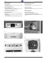
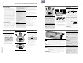
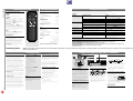
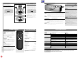
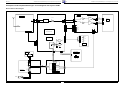
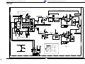
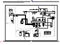
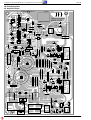
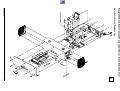
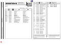
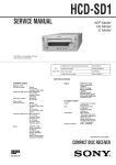
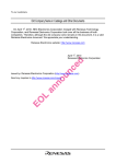
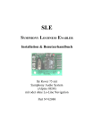
Service Manual
HiFi
RBX 1-RF
Zusätzlich erforderliche
Unterlagen für den Komplettservice
Additionally required
Service Manuals for the Complete Service
Service
Manual
Service
Manual
RBX 1-RF
Sicherheit
Safety
Sach-Nr./Part No.
72010-752.20
Sach-Nr./Part No.
72010-800.00
Btx * 32700 #
Sachnummer
Part Number 72010-752.20
Änderungen vorbehalten
Subject to alteration
Printed in Germany
VK233 0397
Allgemeiner Teil / General Section
RBX 1-RF
Es gelten die Vorschriften und Sicherheitshinweise
gemäß dem Service Manual "Sicherheit", Sach-Nummer 72010-800.00, sowie zusätzlich die eventuell
abweichenden, landesspezifischen Vorschriften!
The regulations and safety instructions shall be valid
as provided by the "Safety" Service Manual, part
number 72010-800.00, as well as the respective
national deviations.
GB
D
Inhaltsverzeichnis
Table of Contents
Seite
Page
Allgemeiner Teil ............................ 1 - 2 … 1 - 5
General Section ............................. 1 - 2 … 1 - 6
Meßgeräte / Meßmittel ...............................................................
Servicehinweis ..........................................................................
Ausbauhinweise .........................................................................
Bedienhinweise ..........................................................................
Technische Daten ......................................................................
Test Equipment / Aids ................................................................
Service Hint ...............................................................................
Disassembly Instructions ...........................................................
Operating Hints ..........................................................................
Specifications .............................................................................
1-2
1-2
1-3
1-4
1-5
1-2
1-2
1-3
1-5
1-6
Schaltpläne und
Druckplattenabbildungen ........... 2 - 1 … 2 - 12
Circuit Diagrams and
Layout of PCBs ........................... 2 - 1 … 2 - 12
Blockschaltbild .......................................................................... 2 - 1
Bauteilhinweise ....................................................................... 2 - 10
Schaltpläne
Prozessorplatte ........................................................... 2 - 3, 2 - 5
Netzplatte ............................................................................. 2 - 5
Netzschalterplatte ................................................................ 2 - 5
LED-Platte ............................................................................ 2 - 5
Schalterplatte ....................................................................... 2 - 6
NF-Verstärkerplatte ..................................................... 2 - 7, 2 - 9
Trafo ................................................................................... 2 - 10
Druckplattenabbildungen
Prozessorplatte .................................................................. 2 - 11
Netzplatte ........................................................................... 2 - 11
Netzschalterplatte .............................................................. 2 - 11
LED-Platte .......................................................................... 2 - 11
Schalterplatte ..................................................................... 2 - 11
NF-Verstärkerplatte ............................................................ 2 - 12
Block Diagram ........................................................................... 2 - 1
Hints on Components ............................................................. 2 - 10
Circuit Diagrams
Control Board .............................................................. 2 - 3, 2 - 5
Power Board ........................................................................ 2 - 5
Power Switch Board ............................................................. 2 - 5
LED Board ........................................................................... 2 - 5
Switch Board ........................................................................ 2 - 6
AF Amplifier Board ............................................................... 2 - 7
Trafo ................................................................................... 2 - 10
Layout of PCBs
Control Board ..................................................................... 2 - 11
Power Board ...................................................................... 2 - 11
Power Switch Board ........................................................... 2 - 11
LED Board ......................................................................... 2 - 11
Switch Board ...................................................................... 2 - 11
AF Amplifier Board ............................................................. 2 - 12
Explosionszeichnung
und Ersatzteilliste ......................... 3 - 1 … 3 - 2
Exploded View and
Spare Parts List ............................. 3 - 1 … 3 - 2
Explosionszeichnung ................................................................ 3 - 1
Ersatzteilliste ............................................................................. 3 - 2
Exploded View .......................................................................... 3 - 1
Spare Parts List ........................................................................ 3 - 2
Allgemeiner Teil
General Section
Meßgeräte / Meßmittel
Test Equipment / Aids
Beachten Sie bitte das GRUNDIG Meßtechnik-Programm, das Sie
unter folgender Adresse erhalten:
Please note the Grundig Catalog "Test and Measuring Equipment"
obtainable from:
GRUNDIG electronics GmbH
Würzburger Str. 150
D-90766 Fürth/Bay
Tel. 0911/703-0, Fax 0911/703-4479
GRUNDIG electronics GmbH
Würzburger Str. 150
D-90766 Fürth/Bay
Tel. 0911/703-0, Fax 0911/703-4479
Servicehinweis
Service Hint
Das HF-Empfängerteil wird im Defektfall komplett getauscht.
The RF Receiver is to be exchanged completely in case of any
defect.
1-2
GRUNDIG Service
RBX 1-RF
Allgemeiner Teil / General Section
Ausbauhinweise
Disassembly Instructions
1. Chassis ausbauen
- Die 6 Schrauben A (Fig. 1) in der Rückwand herausschrauben und
das Chassis herausziehen.
1. Removing the Chassis
- Undo 6 screws A (Fig. 1) on the rear and pull out the chassis.
2. Hochton-Lautsprecher ausbauen
- Chassis ausbauen (Pkt. 1).
- Durch Druck auf den Lautsprechermagneten B (Fig. 2) kann der
Lautsprecher nach außen herausgedrückt werden.
2. Removing the Tweeter
- Remove the Chassis (para 1).
- By pressing on the magnet B of the speaker (Fig. 2) it can be pushed
out.
3. Tiefton-Lautsprecher ausbauen
- Die 4 Schrauben C (Fig. 3) herausschrauben.
3. Removing the Woofer
- Undo 4 screws C (Fig. 3).
4. Bedieneinheit ausbauen
- Die 5 Schrauben D (Fig. 4) herausschrauben und die Blende E
abnehmen.
- Die 2 Schrauben F herausschrauben und die Bedieneinheit nach
vorne herausziehen.
- Beim Zusammenbau auf korrekten Sitz der Blende G achten.
4. Removing the Operating Panel
- Undo 5 screws D (Fig. 4) and take off the cover E.
- Undo 2 screws F and pull out the operating panel.
- When reassembling take care of the correct position of the
cover G.
Fig. 1
Fig. 2
A
A
B
Fig. 4
D
D
E
D
Fig. 3
Fig. 5
F
F
C
C
G
GRUNDIG Service
1-3
Hinweis: Dieses Kapitel enthält Auszüge aus der Bedienungsanleitung. Weitergehende Informationen entnehmen Sie bitte der gerätespezifischen Bedienungsanleitung, deren
Sachnummer Sie in der entsprechenden Ersatzteilliste finden.
EINLEITUNG
Einleitung
Aktiver Lautsprecher RBX1-RF
• RBX1-RF ist ein aktiver Lautsprecher mit internem RF
(Radiofrequenz)-Schaltkreis zum Empfang von
Audiosignalen, ausgestrahlt durch Geräte, die mit
einem RF-Sender ausgestattet sind, wie z. B. der
Verstärker V14DPL-RF
• RBX1-RF ist für Stereo- und hinteren Surroundgebrauch
geeignet. Als Surround-Lautsprecher übernimmt
RBX1-RF den Klang des hinteren Kanals, wenn
Dolby Pro Logic als Betriebsart am Verstärker
gewählt wurde. Als Stereo-Lautsprecher gibt RBX1RF den Stereoklang wieder, wenn der Verstärker auf
Betriebsart Stereo oder 3-Kanal-Modus gesetzt ist.
• Im Stereomodus kann die Lautstärke, unabhängig
von der Lautstärke anderer angeschlossener Lautsprecher, über die Fernbedienung gesteuert werden.
• Der aktive kabellose Lautsprecher RBX1-RF, basiert
auf dem akustischem Prinzip der Space Fidelity.
Dieses Prinzip bietet Ihnen den bestmöglichen
Stereo- und Surroundeffekt mit nur einem einzigen
Lautsprecher. Es sind keine Verbindungskabel nötig.
Centerlautsprecher CLB
• Der Centerlautsprecher CLB hat eine Sinusleistung
von 60 W bei 4 Ohm Impedanz und ist mit zwei
Lautsprecherbuchsen ausgestattet, die den Anschluß
an einen Verstärker ermöglichen.
RF-Verstärker oder Receiver
• Der Grundig Verstärker oder Receiver, der mit
diesem aktiven kabellosen Lautsprecher in Betrieb
genommen wird, sollte mit einem RF-Sender für den
hinteren Kanal oder Stereo-Raum-B ausgestattet sein.
• Die Radiotechnologie kann für den hinteren Lautsprecher in Dolby Prologic, aber auch für Stereoempfang benutzt werden. Dies ermöglicht Ihnen,
den Klang im ganzen Haus zu genießen, da Sie
beliebig viele Lautsprecher anschließen können.
AUFSTELLEN + ANSCHLUß DER LAUTSPRECHER
• Die Zusammenstellung RF-Verstärker oder
Receiver mit RBX1-RF ist die beste Lösung für
Home-Cinema-Installationen, die außerdem
die Möglichkeit der Mehrraumfunktion
bietet, deren Installation überaus einfach ist.
Auspacken
Haben Sie DPLS-RF gekauft, sollten die
folgenden Teile im Lieferumfang enthalten sein:
• 1x kabelloser Lautsprecher RBX1-RF
• 1x Centerlautsprecher CLB
• 1x Verbindungskabel für CLB
• 1x Fernbedienung für RBX1-RF
• 2x Batterien für Fernbedienung
• 1x Ident Dokument
• 1x Bedienungsanleitung
Haben Sie RBX1-RF gekauft, sollten die
folgenden Teile im Lieferumfang enthalten sein:
• 1x kabelloser Lautsprecher RBX1-RF
• 1x Fernbedienung für RBX1-RF
• 2x Batterien für Fernbedienung
• 1x Ident Dokument
• 1x Bedienungsanleitung
Privatsphäre
Bitte beachten Sie, daß bei der Übertragung
von RF-Signalen keine Kodierung
vorgenommen wird.
Das übertragene RF-Signal kann auch von
einer anderen RBX1-RF oder einem RF-Receiver,
z. B. eines Nachbarn, aufgenommen werden.
Dolby Pro Logic
DOLBY PRO LOGIC hergestellt unter Lizenz von
Dolby Laboratories Licensing Corporation.
DOLBY, das Doppel-D-Symbol d und ‘PRO
LOGIC’ sind Warenzeichen der Dolby Laboratories
Licensing Corporation
Hauptfunktionen Ihrer Lautsprecher
RBX1-RF:
• RF-Empfänger für Surround- oder Stereo-Raum-BAnschluß.
• Auswahl von Stereo- und Surround-Modi.
• Automatisches Ein- und Ausschalten von Standby
(im Surround-Modus).
• Automatisch Standby ein (Stereo) - Standby aus
über die Fernbedienung.
• Eingebaute elektronische Lautstärkekontrolle (in
Surround über den Verstärker, in Stereo über die
Fernbedienung).
• Eingebaute elektronische Klangsteuerung in
Stereo über die Fernbedienung.
CLB:
• Magnetisch abgeschirmter Lautsprecher.
• Lautsprecheranschlußklemmen.
• 60 / 90 W Sinus- / Musikleistung.
SURROUND ODER STEREO INSTALLATION
Der RBX1-RF Lautsprecher ist auf Surround- als
auch Stereogebrauch ausgerichtet.
Installation als Home Cinema
• Die Box RBX1-RF, als hintere Surround-Box,
sollte hinter dem Hörer im Raum aufgestellt
werden und der Centerlautsprecher CLB
sollte in der Mitte zwischen beiden Frontlautsprechern, z.B. unter oder auf dem Fernsehgerät, aufgestellt werden
• Setzen Sie den Schieber an der Rückseite
des Lautsprechers in Position SURROUND.
STEREO
CLB
TV
LEFT
RIGHT
Die RBX1-RF kann auch in einem Nebenraum
als Stereolautsprecher verwendet werden.
– Als Stereolautsprecher in einem Nebenraum
kann die RBX1-RF vor dem Hörer aufgestellt
werden. Das Space-Fidelity-Konzept bietet
ein phantastisches Stereoklangbild
innerhalb des gesamten Hörraums.
• Setzen Sie den Schieber an der Rückseite
der Box in Stellung STEREO.
STEREO
SURROUND
MODE
MODE
RBX1-RF
HOME CINEMA
ROOM B
RBX1-RF
• Der Lautsprecher RBX1-RF kann mit zwei Schrauben an
einer Wand angebracht werden.
Die Rückseite der Box ist mit 10 mm “Abstandhaltern”
versehen, die die Belüftung der Box sicherstellen.
RIGHT
CENTRE SPEAKER
–
+
525 mm
RF ANTENNA
CD
PHONO
TV/AUX
IN
TAPE
OUT
IN
VCR
OUT
TUNER
8.5 mm
L
RBX1-RF
Aufstellen der Lautsprecher
Allgemeine Hinweise für das Aufstellen
Stellen Sie die Lautsprecher möglichst nicht in
einer Ecke oder auf dem Boden auf, da hierdurch
die tiefen Töne zu sehr verstärkt werden. Durch
das Aufstellen der Lautsprecher hinter
Möbelstücken, Vorhängen usw. wird die
Wiedergabe von hohen Tönen und damit der
Stereo-Effekt erheblich beeinträchtigt. Der Hörer
sollte noch alle Lautsprecher ‘sehen’ können.
Sie können die beste Position für Ihre Lautsprecher
finden, wenn Sie das Bild (oben) beachten. Im
allgemeinen sollten die Lautsprecher möglichst
symmetrisch im Raum angeordnet werden.
Aufstellen des Centerlautsprechers CLB
Der Centerlautsprecher sollte in der Mitte zwischen
beiden Frontlautsprechern, z.B. unter oder auf dem
Fernsehgerät, aufgestellt werden. Die optimale
Höhe für den Centerlautsprecher entspricht der
Ohrhöhe (im Sitzen).
Hinweis: Um Bildstörungen beim Fernsehgerät zu
vermeiden, ist der CLB Lautsprecher magnetisch
abgeschirmt.
8.5 mm
Hinweis: Bevor Sie den Lautsprecher an der Wand anbringen,
stellen Sie bitte sicher, daß der korrekte RF-Übertragungskanal und Surround- oder Stereomodus,wie im Anschluß
und auf der folgenden Seite beschrieben, gewählt wurden.
• Wollen Sie Ihren Lautsprecher in Regalwänden oder
auf einem Tisch aufstellen, sorgen Sie bitte für ausreichende Belüftung des Gerätes. Ein Freiraum von
mindestens 3 cm seitlich und oberhalb des Lautsprechers
sowie 5 cm an der Rückseite sind empfehlenswert.
R
Anschließen des Centerlautsprechers CLB
Auswahl des RF-Übertragungskanals
m
8m
1
2
3
• Verbinden Sie das Kabel des CLBLautsprechers mit den Klemmen CENTRE
SPEAKER Ihres Verstärkers.
• Achten Sie beim Anschließen der AnschlußLitzen darauf, daß keine Drähte seitlich abstehen. Diese können Kurzschlüsse verursachen.
• Eine der Isolierung der Lautsprecherkabel ist
mit einer Farbe oder einer Rille gekennzeichnet. Die gekennzeichnete Ader wird an die
rote Klemme angeschlossen, die Ader ohne
Kennzeichnung an die schwarze Klemme.
Da bei einigen Übertragungsfrequenzen Störungen durch
Sender der Nachbarn oder elektronische Anlagen
auftreten können, haben Sie die Möglichkeit, zwischen 7
Übertragungskanälen zu wählen.
• Wählen Sie den Übertra1234567
gungskanal an der RBX1-RF
mit dem Schieber CHANNEL
an der Rückseite der Box.
CHANNEL
• Schalten Sie den Verstärker
ein und drücken Sie die Taste CHANNEL.
– Im Display erscheint für 5 Sekunden der ausgewählte
Übertragungskanal, z. B. CHANNEL1.
• Wählen Sie innerhalb dieser 5 Sekunden denselben
Kanal, der an RBX1-RF gewählt wurde.
Netzanschluß
• Verbinden Sie das Netzkabel der Box mit einer Wandsteckdose (230V~, 50/60 Hz).
Ein- und Ausschalten des RBX1-RF
• Stellen Sie sicher, daß STEREO oder
3-CHANNEL am Verstärker ausgewählt
wurde.
– Im Stereomodus können Sie den aktiven
Lautsprecher über seine Fernbedienung
steuern. Siehe Seite 8.
HINWEIS: die Reichweite des RF-Signals liegt
im Freien bei 30 m. Diese Distanz wird in
Räumen durch Wände eingeschränkt. In wie
weit, hängt vom Baumaterial ab.
Sie können den RBX1-RF ein- und ausschalten mit dem
Netzschalter POWER.
Ist der Lautsprecher über den Powerknopf ausgeschaltet, ist
er auch vollkommen von der Stromversorgung getrennt (kein
Stromverbrauch).
Die gelbe LED in der Mitte des Netzschalters leuchtet, wenn
das Gerät angeschaltet wurde oder sich in Standby befindet.
Stand by
Im SURROUND-Modus:
In diesem Modus wird der Lautsprecher automatisch
aktiviert, sobald ein korrektes RF-Signal empfangen wird.
Der Lautsprecher stellt sich automatisch auf Standby, wenn
Vorderseite des RBX1-RF
während 5 Sekunden keine RF-Signale vom Verstärker
POWER
Zum Ein- und Ausschalten des Lautsprechers. Die gelbe LED in der Mitte des Netzempfangen werden. Er bleibt in Standby bis wieder ein
schalters leuchtet wenn das Gerät angeschaltet wurde oder sich in Standby befindet.
Signal empfangen wird.
OPERATE 6 blinkt, wenn die Einstellungen der Box nicht mit dem Verstärker übereinstimmen. Der Im STEREO-Modus:
2-Positionen-Schieber an der Rückseite muß in die richtige Stellung gebracht werden Sie können den RBX1-RF mit der Fernbedienung (Taste y) in
(STEREO oder SURROUND). Anzeige blinkt auch, wenn keine RF-Signale
STAND BY schalten. Der Lautsprecher stellt sich auch auf
empfangen werden. Während Audioempfang leuchtet 6 stetig.
Standby, wenn während 5 Sekunden keine RF-Signale vom
MUTE 6
blinkt, sobald die Funktion MUTE oder SPEAKERS OFF aktiviert wird oder wenn kein Verstärker empfangen werden.
Wollen Sie den Lautsprecher wieder einschalten, drücken
RF-Signal empfangen wird. Während Audioempfang leuchtet 6 stetig.
Sie die Taste y auf der Fernbedienung erneut.
IR SENSOR Um Signale über die Fernbedienung zu empfangen (wenn RBX1-RF auf Stereo
gestellt ist).
Ein- und Ausschalten der Lautsprecher am
Rückseite des RBX1-RF
2-Positionen-Schieber
STEREO/
Mit diesem Schieber können Sie die gewünschte Betriebsart für RBX1-RF auswählen.
SURROUND In Betriebsart SURROUND gibt RBX1-RF den Klang des hinteren Kanals, wie in
einem Pro Logic System, wieder. In diesem Modus werden die Audiosignale des
Lautsprechers von dem RF Verstärker gesteuert. Demnach reagiert der RBX1-RF nicht
auf seine Fernbedienung.
In STEREO wird RBX1-RF als Stereolautsprecher verwendet, der in einem
Nebenraum aufgestellt werden kann. In diesem Modus, können die Audiosignale
über die mitgelieferte Fernbedienung gesteuert werden.
7-Positionen-Schieber
CHANNEL Zur Auswahl des übertragenden Kanals (1-7). Stellen Sie sicher, daß derselbe
Kanal am Verstärker und am Lautsprecher ausgewählt ist.
Verstärker
SPEAKERS A
• Benutzen Sie die Taste SPEAKERS A, um die Lautsprecher, die an die Ausgänge CENTRE SPEAKER und
SPEAKERS angeschlossen sind sowie die RBX1-RF (wenn
in Surround-Modus) ein- und auszuschalten.
RF
• Die Stereo-RF-Übertragung kann nur eingeschaltet
werden, wenn der Verstärker sich im Stereo- oder 3Kanal-Modus befindet.
In dieser Einstellung kann die RBX1-RF in Stereomodus die
Stereosignale des Verstärkers empfangen.
Hinweis: Stellen Sie sicher, daß derselbe Kanal am
Verstärker und am Lautsprecher ausgewählt ist.
RBX 1-RF
GRUNDIG Service
STEREO
LEFT
BEDIENELEMENTE
SURROUND
• Wählen Sie am Verstärker den DOLBY PRO
LOGIC-Modus
– In diesem Modus werden die Audiosignale
des Lautsprechers von dem Verstärker/Receiver gesteuert. Demnach reagiert der
RBX1-RF nicht auf seine Fernbedienung.
TV
Mehr-Raum-Installation
CENTRE
ROOM A
Aufstellen des RBX1-RF kabellosen
Lautsprechers
CLB
CLB
Dolby Pro Logic ist ein Kodiersystem, das es einem
Gerät ermöglicht, vier Klangkanäle aus einem
normalen Stereosignal zu entschlüsseln: Den
mittleren Kanal für bildbezogenen Klang, beide
vorderen Kanäle rechts und links für Stereoklang und
einen Surroundkanal, um Räumlichkeit und Tiefe in
das Klangbild zu bringen.
Allgemeiner Teil / General Section
1-4
Bedienhinweise
TECHNISCHE DATEN
RBX 1-RF
Nur wenn RBX1-RF auf Stereo gesetzt ist
Während des Empfangs von Fernbediensignalen blinkt
OPERATE 6.
VOLUME
Regulieren Sie die Lautstärke mit den Tasten
– VOLUME +.
MUTING
Drücken Sie auf die Taste s, können Sie die Lautstärke stummschalten, um z. B. ein Telefongespräch
entgegenzunehmen. MUTE 6 beginnt zu blinken.
Drücken Sie die Taste s erneut, beenden Sie die
Funktion MUTING. MUTING wird auch aufgehoben,
wenn Sie die Taste VOLUME + drücken.
BASS, TREBLE
Mit den Tasten BASS +/– und TREBLE +/– können
Sie das Klangbild in den Höhen und Bässen individuell verändern. Somit können Sie Unregelmäßigkeiten
in der Akustik des Abhörraumes kompensieren, die
durch Reflektionen an glatten Wänden oder Dämpfung
durch Textilien verursacht werden.
DEFEAT
Betätigen Sie die Taste DEFEAT, schalten Sie den
Einfluß der Klangeinsteller aus. Diese Funktion
versichert damit, daß der Originalklang mit der
höchsten Qualität wiedergegeben wird.
POWER
BASS
DEFEAT TREBLE
VOLUME
Remote Control RC - LS 1
CLB
Sinusleistung.................................................60 W
Musikleistung................................................90 W
Übertragungsbereich .......................85...20.000 Hz
Anzahl der Lautsprecher ........................................3
Art des Mitteltonlautsprechers..................100 mm
Art des Hochtonlautsprechers ....................20 mm
Impedanz ...................................................4 Ohm
Nettovolumen.................................................6,5 l
Abmessungen und Gewicht
B x H x T .........................430 x 125 x 175 mm
Gewicht .............................................ca. 4 kg
Batteriewechsel
Läßt die Reichweite Ihres IR-Gebers nach oder lassen
sich einzelne Funktionen nicht mehr ausführen, sollten
Sie die Batterien auswechseln.
Verwendeter Batterietyp 2x Micro 1,5 Volt LR03,
Größe AAA. Öffnen Sie zum Batteriewechsel den
Deckel des Batteriefaches auf der Rückseite des
Gebers. Achten Sie auf die richtige Polung der
Batterien (Markierung im Batteriefach beachten).
Umwelthinweis:Denken Sie beim Batteriewechsel
daran: Batterien sind Sondermüll.
Operating Hints
Sinusleistung ...........................................2 x 25 W
Musikleistung ..........................................2 x 45 W
Übertragungsbereich .......................40...15.000 Hz
Anzahl der Lautsprecher ........................................4
Art des Mitteltonlautsprechers..................105 mm
Art des Hochtonlautsprechers ....................13 mm
Impedanz ...................................................4 Ohm
Nettovolumen ...........................................ca. 7,1 l
Spannungsversorgung
Betriebsspannung ..................................230 V~
Frequenz .........................................50/60 Hz
max. Leistungsaufnahme .........................125 W
Leistungsaufnahme in Standby...................< 5 W
Abmessungen und Gewicht
B x H x T .........................665 x 215 x 180 mm
Gewicht .............................................ca. 9 kg
Zubehör...................................Bedienungsanleitung
.....................................................Ident Dokument
......................................................Fernbedienung
.......................................zwei Batterien LR03, AAA
........................................Verbindungskabel für CLB
Technische und optische Änderungen vorbehalten !
FEHLERCHECKLISTE
Die folgende Checkliste wird Ihnen helfen, die meisten Probleme, die bei Ihrem Gerät auftreten können, zu lösen. Bevor Sie die unten stehende Checkliste
durchgehen, sollten Sie überprüfen ob das Netzkabel (RBX1-RF) und die Lautsprecherkabel (CLB) fest angeschlossen sind.
Wenn der Fehler mit Hilfe der Liste nicht beseitigt werden kann, wenden Sie sich bitte an Ihren Fachhändler.
WARNUNG : Versuchen Sie unter keinen Umständen das Gerät selber zu reparieren, da die Garantie dadurch ihre Gültigkeit verliert.
Problem
Kein Ton
Kein Klang, Klangstörungen
oder OPERATE 6 blinkt
jede Sekunde
Klangverzerrungen
Übersteuerter Klang
Mögliche Ursache
Lösung
VOLUME zu niedrig eingestellt
Drücken Sie VOLUME + auf der Fernbedienung (in
STEREO-Modus) oder erhöhen Sie die Lautstärke am
Verstärker (in SURROUND-Modus)
Schalten Sie RBX1-RF mit der Taste POWER ein.
Drücken Sie die Taste SPEAKERS A und/oder RF am Verstärker.
Schalten Sie die MUTING-Funktion aus (Taste s auf Ferngeber).
Wählen Sie an beiden Geräten denselben RF-Kanal aus.
Wählen Sie an beiden Geräten denselben SURROUND
oder STEREO-Modus aus.
Stellen Sie den Lautsprecher dichter beim Verstärker auf.
RBX1-RF ist nicht eingeschaltet
SPEAKERS A/SPEAKERS RF am Verstärker nicht eingeschaltet
MUTING-Funktion eingeschaltet
Die RF-Kanäle des RBX1-RF und des Verstärkers stimmen nicht überein.
Die Einstellung von SURROUND/STEREO an Box und
Verstärker stimmen nicht überein.
Der Lautsprecher ist zu weit vom Verstärker entfernt oder die RF-Übertragung wird durch Gegenstände zwischen beiden Geräten gestört.
SPEAKERS RF ist nicht eingeschaltet (nur STEREO-Modus)
Verzerrungen durch Alarmanlagen an Haus oder Auto.
Elektromagnetische Aufladung von anderen elektrischen
oder elektronischen Anlagen.
Übertriebene Einstellung der hohen oder tiefen Töne.
RBX 1-RF
GRUNDIG Service
KLANGEINSTELLUNG
Klangeinstellung über die Fernbedienung
Drücken Sie die Taste SPEAKERS RF am Verstärker.
Positionieren Sie den RBX1-RF anders.
Wählen Sie einen anderen RF-Kanal sowie am
Lautsprecher als auch am Verstärker.
Drücken Sie DEFEAT auf der Fernbedienung oder stellen Sie
den Klang durch BASS und TREBLE auf Ihren Geschmack ein.
Wählen Sie einen anderen RF-Kanal an Lautsprecher
und Verstärker.
Batterien auswechseln.
Der Klang kann über den Verstärker gesteuert werden oder
wählen Sie STEREO an Verstärker und Lautsprecher, um
die Fernbedienung verwenden zu können.
Gehen Sie näher an das Gerät.
RBX1-RF reproduziert Klang von Störungen evtl. durch Installationen der Nachbarn.
einer anderen Programmquelle.
Die Fernbedienung geht nicht Die Batterien sind leer
RBX1-RF wurde auf SURROUND gesetzt. In diesem Fall wird
der Klang über den Verstärker kontrolliert.
Zu großer Abstand oder falscher Winkel zum Gerät
Pflege des Gerätes
• Gehäuse mit weichem, staubbindendem Lappen reinigen.
• Polier- und Reinigungsmittel können die Oberfläche des Gehäuses beschädigen.
Dieses Gerät ist funkentstört entsprechend den geltenden EG-Richtlinien.
Dieses Gerät entspricht der Sicherheitsbestimmung VDE 0860 und somit der internationalen Sicherheitsvorschrift EN 60065.
Dieses Produkt erfüllt die europäischen Richtlinien 89/336/EEC, 73/23/EEC und 93/68/EEC.
Dem 'Bundesamt für Zulassungen in der Telekommunikation' (BZT) wurde angezeigt, daß das Gerät in Verkehr gebracht wurde. Ihm wurde auch die
Berechtigung eingeräumt, die Serie auf Einhaltung der Bestimmungen zu überprüfen.
Note: This chapter contains excerpts from the operating instructions. For further particulars please refer to the appropriate user instructions the part number of which is indicated in the
relevant spare parts list.
INTRODUCTION
Introduction
1-5
• The package RF amplifier (or receiver) and DPLS-RF is
the best solution for Home Cinema installation providing also a true multiroom solution of which the installation is as easy as connecting a mains plug.
If you have purchased the DPLS-RF, the
following parts should be included in the
packing cartons:
• 1x RBX1-RF wireless speaker
• 1x CLB center speaker
• 1x connection cable for CLB
• 1x remote control for RBX1-RF
• 2x batteries for remote control
• 1x ident card.
• 1x instructions for use
CONNECTING AND SETTING UP THE SPEAKERS
Dolby Pro Logic
Dolby Pro Logic is a coding system that enables a
set to decode 4 sound channels out of a normal
stereo signal: the centre channel for picture related
sounds, both front left and right channels for stereo
sounds and one surround channel to bring room
and depth to the scene.
Setting up the RBX1-RF wireless speaker
CLB
CLB
• The RBX1-RF speaker can be mounted to a wall,
using 2 screws. The back of the speaker is provided
with 10 mm ‘spacers’ to ensure ventilation of the
speaker.
TV
LEFT
RIGHT
525 mm
CENTRE SPEAKER
–
+
RF ANTENNA
Dolby Pro Logic manufactured under license from
Dolby Laboratories Licensing Corporation.
DOLBY, the double-D symbol d and ‘PRO LOGIC’
are trademarks of Dolby Laboratories Licensing
Corporation.
8.5 mm
CD
PHONO
TV/AUX
IN
TAPE
OUT
IN
VCR
OUT
TUNER
L
R
RBX1-RF
If you have purchased the RBX1-RF, the
following parts should be included in the
packing cartons:
• 1x RBX1-RF wireless speaker
• 1x remote control for RBX1-RF
• 2x batteries for remote control
• 1x ident card.
• 1x instructions for use
Privacy
Please note that at the transmission of the RF
signals, no coding system is used.
The transmitted RF signals can also be picked
up by another RBX1-RF or an RF receiver set
situated at a neighbour.
Main features of your speakers
RBX1-RF:
• RF-receiver for surround use or stereo room B
• Selection of Surround and Stereo modes
• Automatic standby on/off (in SURROUND mode)
• Automatic standby on (stereo mode) standby off via remote control
• Built-in electronic volume control
(in surround mode via the amplifier and in stereo
mode via the remote control)
• Built-in electronic tone control in stereo mode via
the remote control
CLB:
• Magnetic shielded speaker
• Push pull speaker terminals
• 60 W Nominal/90 W Music power handling
capacity.
Speaker positioning
General hints for positioning
Avoid positioning the speakers in a corner or on
the floor, as this will boost the bass tones too
much. Placing the speakers behind curtains,
furniture etc. will reduce the treble response, thus
reducing the stereo effect considerably. The
listener should always be able to ‘see’ the
speakers.
You can find the best position for your speakers
by following the picture on the top of the page.
The speakers should always be arranged as
symmetrically as possible in the room.
Positioning the centre speaker CLB
The centre speaker should be placed in the
centre between both front speakers, e.g.
underneath or on top of the TV. The best height
for the centre speaker is at the height of the
listener’s ears (while seated).
Note: to avoid interference with the TV picture,
the CLB speaker is magnetically shielded.
Connecting the centre speaker CLB
8.5 mm
Note: Before mounting the speaker to a wall, please
make sure that the correct RF transmission channel and
the surround or stereo mode is selected as described
next.
• If you want to set up your speaker on a shelf or
table, always ensure that sufficient ventilation is
available. An open space of at least 3 cm at the
sides and the top, and 5 cm at the back of the
speaker is required.
Selecting the RF transmission channel
m
8m
1
2
3
• Connect the cable of the CLB speaker to the
terminals CENTRE SPEAKER on the amplifier.
• Make sure that speaker wires are properly and
tightly twisted to avoid protruding individual
wires. These can cause shorts.
• One of the wires of a loudspeaker cable is
marked, e.g. with a colour or rib. Connect the
marked wire to the red terminal, the nonmarked wire to the black one.
As on some transmission frequencies interferences from
neighbour transmitters or electronic equipment may occur,
you can to select between 7 transmission channels.
• Select on the RBX1-RF the
1234567
RF transmission channel with
the slide switch CHANNEL
on the back of the speaker.
CHANNEL
• Switch on the RF amplifier
(or receiver) and press the CHANNEL button.
– The display shows during 5 seconds the selected
transmission channel e.g. CHANNEL1.
• Select within these 5 seconds the same channel as
selected on the RBX1-RF.
Mains connection
• Connect the mains plug of the RBX1-RF to the wall
socket (230V~, 50/60 Hz).
Allgemeiner Teil / General Section
Active speaker RBX1-RF
• The RBX1-RF is an active speaker with an internal RF
(radio frequency) circuitry, for reception of the audio
signals transmitted by sets equipped with RF
transmitter like for example the V14DPL-RF.
• The RBX1-RF is configurable for surround and for
stereo use. As a surround speaker, the RBX1-RF will
emit the sound of the rear channel if Dolby Pro Logic
mode is selected on the amplifier. As a stereo
speaker, the RBX1-RF will emit the normal stereo
sound if the amplifier is in stereo or 3-channel mode.
• In stereo mode, the volume of the speaker can be
controlled (via remote control) independent of the
volume of the other (wired) speakers.
• The active wireless speaker RBX1-RF, uses the Space
Fidelity acoustic system. This system will give you the
best stereo and surround effect possible with only one
single speaker. No connection cables are necessary!
Centre speaker CLB
• The centre speaker CLB can handle 60 W Nominal
power, 4 Ohm impedance and is provided with two
speaker terminals for connection to the amplifier.
RF amplifier or receiver
• The Grundig amplifier or receiver that drives this
wireless active speaker should be equipped with an
RF transmitter for the rear channel or stereo room B.
• The radio transmitter can be used for the rear
speaker in Pro Logic mode but also for stereo to
enable you to enjoy the sound of your system
throughout your house. This, thanks to the fact that
you can install an unlimited number of speakers.
Unpacking
Home cinema installation
ROOM A
STEREO
CLB
TV
– As a rear surround speaker, the RBX1-RF
should be positioned behind the listener in
the room and the centre speaker CLB in the
centre between both front speakers, e.g.
underneath or on top of the TV.
• Set the 2-position slide switch on the back of
the RBX1-RF to SURROUND.
OPERATING ELEMENTS
LEFT
RIGHT
STEREO
• Make sure that normal STEREO or
3-CHANNEL mode is selected on the
amplifier.
– In stereo mode, you can control the active
speaker via the supplied remote control as
described on page 14.
NOTE: the reach of the RF signal is 30 m in
open air. This distance will be reduced if
walls are in between, depending very much
on the construction materials.
RBX1-RF
ROOM B
RBX1-RF
STEREO
SOUND CONTROL
Changing the batteries
This button is used for switching the unit on and off. The yellow 6
in the middle of the button indicates that the unit is on or in standby mode.
OPERATE 6 This 6 is blinking, any time the set is not matched with the mode of the amplifier.
The 2-position slide switch on the back must be set to the correct mode (STEREO or
SURROUND) It also blinks if there are no RF signals received. On an audio session
this 6 is always on.
MUTE 6
This 6 is blinking any time the commands MUTE and SPEAKERS OFF are activated
or if there are no RF signals received. On an audio session this 6 is always on.
IR SENSOR To receive signals from the supplied remote control (if RBX1-RF is set to STEREO mode).
POWER
DEFEAT TREBLE
VOLUME
Remote Control RC - LS 1
Nominal power.......................................2 x 25 W
Music power ..........................................2 x 45 W
Transmission range..........................40...15.000 Hz
Number of speakers.............................................4
Mid range type....................................105 mm
Tweeter type .........................................13 mm
Impedance .................................................4 Ohm
Volume approx. ..............................................7,1 l
Power supply
Voltage ...............................................230 V~
Frequency........................................50/60 Hz
Max. power consumption .......................125 W
Standby power consumption.....................< 5 W
Dimensions & weight
W x H x D.......................665 x 215 x 180 mm
Weight ........................................approx. 9 kg
Accessories.................................Instructions For Use
............................................................Ident card
.......................................................remote control
............................2 x 1.5V micro batteries size AAA
............................................Speaker cable for CLB
Subject to technical alterations and alterations in
styling E. and O.E.
Switching the speakers on and off on the
amplifier
SPEAKERS A
Back of the RBX1-RF
• Use the SPEAKERS A button to switch on and off the
2-position slide switch
speakers connected to the CENTRE SPEAKER and
SPEAKERS terminals and the rear speaker RBX1-RF (if set
STEREO/
This switch is used to select the desired mode of the RBX1-RF.
to SURROUND mode).
SURROUND If set to SURROUND, the RBX-1 RF acts as a rear speaker in a Pro Logic system. In
this mode the audio signal is controlled by the RF-amplifier. The speaker does not
RF
react to its remote control
• The stereo RF transmission can only be switched on when
If set to STEREO, the RBX-1 RF acts as a stereo speaker which can be placed in a
the amplifier is in normal stereo or in
second room. In this mode, the audio signal can be controlled by the supplied remote
3-CHANNEL mode.
control.
In this mode, an RBX1-RF set to STEREO mode can
receive the stereo signal from the amplifier.
7-position slide switch
CHANNEL To select the RF reception channel (1–7). Make sure that the same channel is
Note: make sure that the CHANNEL selection is the same
selected on the speaker and the amplifier
on the amplifier and on the speaker.
TROUBLESHOOTING
The following checklist will help you to correct most of the problems that can occur with your unit.
Before you go through the following list, verify if the mains cable (RBX1-RF) and the cables to the speaker (CLB) are securely connected.
If the following list does not help, please consult your HiFi dealer.
WARNING : Under no circumstances should you try to repair the set yourself, as this would invalidate the guarantee.
Problem
No sound.
Possible cause
VOLUME not adapted
RBX1-RF is not switched on
SPEAKERS A/SPEAKERS RF on the amplifier not switched on
MUTING function switched on
No sound, sound cuts
appear or OPERATE 6 is
blinking every second
CLB
Nominal power ............................................60 W
Music power................................................90 W
Transmission range..........................85...20.000 Hz
Number of speakers.............................................3
Mid range type....................................100 mm
Tweeter type .........................................20 mm
Impedance .................................................4 Ohm
Volume approx. ..............................................6,5 l
Dimensions & weight
W x H x D.......................430 x 125 x 175 mm
Weight ........................................approx. 4 kg
In SURROUND mode:
In this mode the speaker is automatically activated when the
correct RF signals are received. The speaker is also
switched to STAND BY automatically if during 5 minutes no
RF-signals are received from the amplifier and remains in
standby until RF-signals are received again.
In STEREO mode:
You can switch the speaker to STAND BY with the y button
on the remote control. The speaker is also switched to
STAND BY automatically if during 5 minutes no RF-signals
are received from the amplifier.
When you want to switch your speaker on again, simply
press y on the remote control again.
Sound interferences
Poor sound
The RBX1-RF produces sound
from another sound source
The remote control does
not work.
The RF channels selected on the amplifier and RBX1-RF
speaker do not match
The SURROUND/STEREO modes on amplifier and speaker
do not match
The speaker is too far away from the amplifier or the RFsignal is distorted by materials situated between the
speaker and the amplifier
The SPEAKERS RF is not switched on (STEREO mode only)
Interferences from home security and car locking systems
Electromagnetic radiation from other electric or electronic equipment.
Excessive adjustment of the bass or treble tones
Interference from a neighbour transmitter
Batteries empty
The RBX1-RF is set to SURROUND mode and in this
case the sound is controlled by the amplifier.
Too far away from the unit, or pointed at an excessive angle
Remedy
Press VOLUME + on the remote control (in STEREO mode)
Turn up the volume on the amplifier (in SURROUND mode)
Switch on the RBX1-RF with the POWER button.
Press the SPEAKERS A and/or RF on the amplifier.
Switch off the MUTING function
( s button on the remote control).
Select on both units the same RF channel
Select on both units the same SURROUND or STEREO
mode
Move the speaker nearer to the amplifier
Press the SPEAKERS RF switch on the amplifier.
Try to move the RBX1-RF to another position
Select another RF channel both on amplifier and RBX1-RF
Press DEFEAT on the remote control
Adjust BASS and TREBLE to your personal taste
Select another RF channel on amplifier and speaker
Replace the batteries.
The sound can be controlled by the amplifier or select
the STEREO mode on speaker and amplifier to be able to
use the remote control.
Move nearer to the unit
Caring for the unit
• Wipe the housing clean with a soft, dry and antistatic cloth.
• Polishing and cleaning agents can damage the surface of the housing.
This unit meets the CEE regulations concerning interference radiation.
This unit complies with the safety regulations according to VDE 0860/BS 415 and thus with the international safety regulation EN 60065.
This product fulfills European directives 89/336/EEC, 73/23/EEC and 93/68/EEC.
RBX 1-RF
GRUNDIG Service
If the range of your infrared remote control seems to
decrease, or if certain individual functions can no longer
be carried out, you should replace the batteries.
Two micro 1.5 Volt LR03 size AAA are required. To
change the batteries, open the compartment on the back
of the remote control. Ensure that the batteries are inserted properly (note the markings in the compartment).
In the interest of the environment: Remember that
batteries must always be disposed of properly.
RBX 1-RF
BASS
Front of the RBX1-RF
POWER
TECHNICAL DATA
Sound control via the remote control
Only when the RBX1-RF is set to STEREO mode
During reception of remote control signals the
OPERATE 6 is blinking.
VOLUME
The volume can be adjusted with the – VOLUME + keys.
MUTING
The volume can be completely muted by pressing the
s button on the remote control. This is useful, for
example, if you want to take a telephone call and do
not want to be distracted by music, news, etc., from
your system. The MUTE 6 starts blinking.
The MUTING function can be deactivated by pressing
s again or by pressing the VOLUME + key.
BASS, TREBLE
The BASS +/– and TREBLE +/– keys can be used to
individually adjust the higher and lower frequencies
from the sound of your speaker. In this way, you can
compensate for surrounding acoustic irregularities which
may be caused, for example, by sound reflection behaviour on walls with relatively large, empty surface
areas, or "damping" caused by furniture or other objects.
DEFEAT
The DEFEAT switch can be used to deactivate any
bass and treble adjustment.
This function ensures that the original sound is
reproduced with the highest fidelity.
Stand by
SURROUND
MODE
MODE
HOME CINEMA
You can switch the speaker on and off with the POWER
button.
When the power is switched off, the set is separated from
the mains supply. (no power consumption).
The yellow 6 in the middle of the POWER button indicates
that the unit is on or in standby mode.
The RBX1-RF can also be used as a stereo
speaker in a second room.
– As a stereo speaker in another room, the
RBX1-RF can be positioned in front of the
listener. The ‘Space Fidelity’ concept of the
speaker provides a fantastic stereo sound
everywhere you go in the listening room.
• Set the 2-position slide switch on the back
of the speaker to STEREO.
SURROUND
• Select on the amplifier the DOLBY PRO
LOGIC mode.
– In this mode the audio signal of the speaker
is controlled by the amplifier/receiver and
the RBX1-RF does not react to its remote
control.
Switching the RBX1-RF on and off
Multi-room installation
CENTRE
Allgemeiner Teil / General Section
1-6
SURROUND OR STEREO INSTALLATION
The RBX1-RF speaker is configurable for rear
surround and for stereo use.
RBX 1-RF
Schaltpläne und Druckplattenabbildungen / Circuit Diagrams and Layout of PCBs
RBX 1-RF
Schaltpläne und Druckplattenabbildungen / Circuit Diagrams and Layout of PCBs
Schaltpläne und Druckplattenabbildungen / Circuit Diagrams and Layout of PCBs
Blockschaltbild / Block Diagram
HEATSINK
AUDIO AMPLIFIER BOARD
RF-RX-BOARD
WIRE
CCC3
ACTIVE FILTER
WIRE
TDA 7318
ZIF3
CCC3
WIRE
WIRE
ZIF7
CCC7
KEHLER
TUBE
+12V
ANTENNA
-12V
DC PROT
+Vac
MUTE
-Vac
+12VA
AUDIO
STANDBY
+
JST3
CCC6
PROCESSOR BOARD
ON\OFF
UPROCESSOR
+18V
TUNED
LM7812
+12V
MUTE
CCC6
I.R.
+5V
+
LM7805
-Vac
+Vac
CCC6
JST2
CCC2
SWITCH BOARD
WIRE
WIRE
CCC2
WIRE
WIRE
POWER
SWITCH
JST2
3N3
WIRE
WIRE
FUSE
MAINS BOARD
AC
FILTER
POWER TRANSFORMER
JST2
BN
50Hz/60Hz
230V~
MAINS
BL
GRUNDIG Service
2-1
GRUNDIG Service
2-2
Schaltpläne und Druckplattenabbildungen / Circuit Diagrams and Layout of PCBs
RBX 1-RF
Schaltpläne und Druckplattenabbildungen / Circuit Diagrams and Layout of PCBs
RBX 1-RF
Prozessorplatte
Control Board
DINAMIC BASS EQUALISATION
ON STEREO MODE THE LEVEL IS SET BY THE USER (-79dB UP TO 0 dB)
THE DEFAULT VALUE IS -44dB
PHASE INVERTER
ON PROLOGIC MODE THE VALUE IS SET TO -10dB
+12V
38
27
36 Seite/page 2 - 6
10K
R413
D401
100K
1K
1N4148
68K
470pF
1K
R412
10
R414
+
10U
C486
R468
2.7K
C405
F
1K
F
C402
R408
F
100nF
T401
IC501
-
R470
10K
R411
C408
F
1K
6
0V
NJM4560
7
0V
C403
-12V
28
1/2
IC402
R406
27P
23
8305-293-560
5
+
0V
68K
4
6.8K
F
R407
18nF
68K
R403
470R
NJM4560
1
0V
-
470nF
R438
10
R401
12N
F
F
2
0V
1/2
IC402
+
C484
1U/
+
5
BC338-40
1U/
Surround Mode
3
400 mV (1KHz)
2
4
1
C433
+
24
10U
R441
MUTE
1
21
6
7
20
5
C480
+
+12V
R480
1K
MUTE
P404
68K
22
R460
3
+12V
10U
RB
SUPPLY
2
SPKR
ATT
R490
TREBLE
10
BASS
R429
VOL
10
R1
(+4.5V)
47K
11
SPKR
ATT
TO P108 AUDIO BOARD
R3
R2
R405
8
+
C409
9
10
0V
47K
26
+ GAIN
R4
3
470R
R400
8
I2C BUS DECODER + LATCHES
R404
+
1uF
56K
INPUT
SELECTOR
C404
C422
47K
MUTE
L4
-
C407
F
150nF
R409
L3
12
27P
2.7N
TREBLE
2
NJM4560
1
0V
IC403
F
100nF
22k
13
BASS
VOL
L2
SPKR
ATT
1/2
+
0V
R431
R437
14
47K
2k2
10U
MUTE
(+4.5V)
47K
3
0V
R432
C432
+
25
RB
L1
R434
R436
SPKR
ATT
8305-847-318
1
0V
C401
8305-293-560
R433
-
0V
4
TDA7318
NJM4560
IC401
2
22k
R442
18
1/2
+
0V
IC406
R452
19
100N
C439
F
F
C438
F
16
3
47K
17
100N
C437
+
2.2U
15
400 mV (1KHz)
Surround Mode
Surround Mode
C429
126 mV (1KHz)
C436
C423
400 mV (1KHz)
INPUT SELECTOR ALWAYS WITH GAIN = +6 dB
R402
5.6K
R444
Power Amp. left
+12V
4
6
0V
R419
+
1uF
150nF
C424
R420
2
0V
R416
10K
68k
4
+
6
0V
-
F
R449
NJM4560
7
0V
R428
2.7k
C418
F
470pF
-12V
+
C499
1U/
1n4148
+
C416
D402
1k
1U/
R447
100k
56k
R424
R425
BC338-40
1/2
IC404
1k
470nF
F
C415
-12V
T402
8305-293-560
5
0V
C417
6.8K
-12V
200 mV (1KHz)
R422
R421
10K
10R
R435
1
0V
-
100nF
ON PROLOGIC MODE THE VALUE IS SET TO -10dB
+12V
+
IC404
10
R451
R423
F
100nF
F
100N
ON STEREO MODE THE LEVEL IS SET BY THE USER (-79dB UP TO 0 dB)
THE DEFAULT VALUE IS -44dB
0V
1/2
NJM4560
8
3
470
470
1K
R443
2k2
C457
10
R417
C414
F
4
C413
F
NJM4560
7
0V
R427
5.6k
R439
R446
1/2
+
IC403
-
Power Amp. right
C412
F
100N
10
400 mV (1KHz)
0V
0V
8
18nF
IC401
6
0V
5
7
F
100nF
8305-293-560
C419
NJM4560
68K
1/2
C425
400 mV (1KHz)
Surround Mode
8
+
R418
5
0V
2.7N
100N
C447
F
F
C446
100N
+
2.2U
F
C445
+
22U/50V
C442
330
F
100N
126 mV (1KHz)
Surround Mode
C444
C443
R445
+
100U/25V
+12V_R
(9V)
C458
DBE
+12V
MUTE(FIELD STRENGTH)
100U/25V
2.0V
IC501
47K
47K
C455
+
110mV
12dB
40mV
+12_R
70 Hz
1KHz
+
R426
10
R415
AUDIO_L
AUDIO_R
-12V
CONTROL BOARD
59451-583.94
BAT42
D406
0,47U/100V
PILOT ON/OFF
+
22U/50V
1K
R458
R457
R456
C453
47K
R454
R453
+
22U/50V
C454
B
100U/25V
C452
+
-12V
16
15 Seite/page 2 - 6
1K
C448
+
Av
5k6
P401
20/01/97
FROM RECEIVER BOARD
2-3
GRUNDIG Service
2-4
GRUNDIG Service
RBX 1-RF
Schaltpläne und Druckplattenabbildungen / Circuit Diagrams and Layout of PCBs
RBX 1-RF
Schaltpläne und Druckplattenabbildungen / Circuit Diagrams and Layout of PCBs
Prozessorplatte, Netzplatte, Netzschalterplatte, LED-Platte, Schalterplatte
Control Board, Power Board, Power Switch Board, LED Board, Switch Board
+5v
1
Mute Led
5
2
(+5V)
Operate Led
4
3
3
4
2
5
6
D415
C473
F
D411
1N4148
D409
0.1U
1N4002
D414
1N4002
C474
F
D412
0.1U
D413
F
F
(+5V)
47K
6
R483
47K
P418
(+5V)VUP
R484
BC558B
T413
10K
7
RC-IN
(+5V)
1
P601
+12V
(+5V)
BC546B
P410
7
R605
FROM TRAFO
BOARD
1000U/25V
1N4002
47K
C471
R604
15.1VAC
+18V
0.1U
C476
T601
1N4002
IC407
7805
+5V
0.1U
C472
+
F
0.1U
C477
T500mA
8305-205-703
T602
1N4148
SI401
8305-209-712
power/stdy
D601
D602
mute
operate
18K
R463
R601
330
R602
330
R603
330
IC408
7812
+12V_R
BC546B
0.47U/100V
1K
R461
47K
47K
100K
R469
R462
R471
POWER DOWN
D603
R459
22K
C461
+
(+5V)
T403
BC546B
10
47K
38
47K
+12V_R
22
21
POWER DOWN
1N4148
R491
DC PROTECTION
DC_PROT.
D423
RESET
100K
D424
R492
+
2.2U\100V
C483
STEREO/SURROUND
L401
V REF
22U
1N4148
+
100U\25V
F
0.1U
C482
(+5V)
C481
10
11
MUTE SPEAKERS
31
32
33
12
13
14
15
16
T411
R481
BC546B
10K
+5V
+5V
26
30
47K
18
17
R410
9
20
T412
R430
BC546B
10K
R498
8
3
47K
7
FROM AUDIO
BOARD
4
16
6
19
IC501
M37471M2-477SP
8305-207-501
25 42 23 24
29
10K
5
28
STANDBY2
X IN
35 34
PILOT ON/OFF
4
X OUT
STANDBY1
36
P112
5
P403
MUTE(FIELD STRENGTH)
37
6
1
15
38
R496
39
10K
40
+5V
41
7
2
RC-IN
27
DATA TDA7313
CLOCK TDA7313
F
0.1U
TX\RX
+
1
24C04
8305-602-400
LED BOARD
59451-575.94
2
IC405
47U/10V
C601
47
R606
3
D
MUTE
F401
4MHZ
DATA EEPROM
C488
59852-001.00
GND VOUT VCC
R486
(+5V)
CLOCK EEPROM
IC601
DC_PROT.
IC406
Seite/page 2 - 3
36
R485
-12V R499
P401
Seite/page 2 - 3
+5v
C440
F
R450
POWER BOARD
SW 401
59451-573.94
C502
K
MODE
P405
1
BL
3.3N
C501
K
3.3N
ROOM A
SI501
T1Al
P411
E
F
59451-592.94
R440
POWER SWITCH BOARD
330
0.1U
10k
BN P503
P411
S501
1
SURROUND
G
PIN 42
0
ROOM B
SWITCH BOARD
STEREO
1
59451-574.94
F501
SW401
C
GRUNDIG Service
TRANSFORMER
BL
P502
BN
59451-572.94
gnd
20/01/97
50Hz/60Hz
220V~
MAINS
TO POWER
BN
BL
P501
59401-047.00
CONTROL BOARD
2-5
GRUNDIG Service
2-6
Schaltpläne und Druckplattenabbildungen / Circuit Diagrams and Layout of PCBs
RBX 1-RF
Schaltpläne und Druckplattenabbildungen / Circuit Diagrams and Layout of PCBs
RBX 1-RF
NF-Verstärkerplatte / AF Amplifier Board
+V (+27.0V)
+27V
C161
+
1U/100V
1
R108
1U/100V
1k
0V
5
835-204-876
LM3876
470P
C124
K
7
IC105
10
22k
LEFT CHANNEL
C144
+
C123
K
FROM P404
CONTROL BOARD
400 mV
220P
R109
P108
8305-204-878
9.5V
P103
L101
0V
C102
F
0.22U
C103
F
0.22U
+
C162
22N
R114
C126
K
1U/100V
+
C146
22K
5.6
4
.47U/100V
R111
10
C128
K
-3.5V
5.6
R156
8
R154
R153
22K
3
9
22N
0V
C180
K
09238-170.01
TO LEFT
SPEAKER
22N
-27V
-V (-27.0V)
R112
P104
C127
K
C163
+
C153 to be added
when not in use to use shunt
1U/100V
1
0V
BC546B
8305-204-878
9.5V
0V
0V
L102
09238-170.01
3
R115
22K
-3.5V
5.6
R157
R158
8
5.6
R155
9
10
4
+
C147
C131
K
T104
LM3876
470P
22k
7
IC104
10
100U/25V
1k
47k
R122
5
R116
C150
+
1U/100V
C132
K
RIGHT CHANNEL
220P
R121
400 mV
TO RIGHT
SPEAKER
22N
+V (+27.0V)
+27V
22N
47P
C129
K
22K
22N
C125
K
C190
K
1K
R113
+
C145
100U/25V
R110
22K
T105
BC546B
.47U/100V
0.22U
U.22U
22k
R101
0V (MUTE)
47K
R132
+
C164
+
C148
22K
C107
F
R163
MUTE
C106
F
.47U/100V
DCPROT
-27V
-V (-27.0V)
R118
22K
T106
NF / AF
R120
1K
+
C149
R117
C130
K
22K
47P
47K
R131
-26.4V
(MUTE)
110U/25V
BC546B
-27V
-V (-27.0V)
20/01/97
2-7
GRUNDIG Service
2-8
GRUNDIG Service
RBX 1-RF
Schaltpläne und Druckplattenabbildungen / Circuit Diagrams and Layout of PCBs
NF-Verstärkerplatte / AF Amplifier Board
IC101
7812CV
835-205-712
+12V
OUT
(+24.5V)
IN
0
100
R161
0.1U
R165
C116
F
0.1U
+
C160
C117
F
22U/25V
GND
(+27.0V)
+
C157
4700/40V
+V
REL106
D124
4X
D120
T4L
IN5401
SI102
-V
D118
TO
+
C158
4700/40V
D119
TRAFO
(-27.0V)
P110
T4L
+12VR
100
R162
SI103
REL
-12V
(-24.5V)
IN
GND
1N4148
1N4148
D112
D114
STANDBY
MUTE
+12VR
AUDIO BOARD
59451-583.94
P112
A
-12V
+12V
0.1U
C111
F
0.1U
C112
F
C159
+
22U/25V
STANDBY
DCPROT
OUT
JW2aSN-DC 12V
0
R166
IC103
7912CT
8305-205-911
TO
CONTROL BOARD
P403
20/01/97
GRUNDIG Service
2-9
Schaltpläne und Druckplattenabbildungen / Circuit Diagrams and Layout of PCBs
RBX 1-RF
Bauteilhinweise, Trafo / Notes on Components, Trafo
AENDERUNGEN VORBEHALTEN
SUBJECT TO ALTERATION
SOUS RESERVE DE MODIFIC.
CON RISERVA DI MODIFICA
RES. EL DERECHO DE MODIFIC.
KONDENSATOR/CAPACITOR
CONDENSATEUR/CONDENSATORE/CONDENSADOR
10
ELKO
ELECTROLYTIC
ELECTROLYTIQUE
ELETTROLITICO
ELECTROLITICO
T
WIDERSTAND/RESISTOR
RESISTANCE/RESISTENZA/RESISTENCIA
KSW 0204 DIN
MSW 0204 DIN
KSW 0207 DIN
MSW 0207 DIN
KSW 0309 DIN
KSW 0411 DIN
KSW 0617 DIN
MSW 0309 DIN
NTC
MSW 0414 DIN
TO
100
DRAHT
WIRE
BOBINEE
A FILO
BOBINADA
F
METALLOXYDSCHICHT
METAL OXIDE
A OXYDE METALLIQUE
AD OSSIDO METALLICO
DE CAPA DE OXIDO METALICO
K
RAUSCHARM
LOW NOISE
A SOUFFLE REDUIT
A BASSO RUMORE
DE BAJO RUIDO
G
SCHWER ENTFLAMMBAR
LOW FLAMMABILITY
PEU INFLAMMABLE
A BASSA INFLAMMABILITA
DIFICILMENTE INFLAMABLE
V
SICHERUNGSWIDERSTAND
SAFETY RESISTOR
FUSIBLE
DI SICUREZZA
RESISTENCIA FUSIBLE
P
TANTAL ELKO
TANTALUM ELECTROLYTIC
ELECTROLYTIQUE AU TANTALE
ELETTROLITICO AL TANTALIO
ELECTROLITICO DE TANTALO
FOLIE
FOIL
A FEUILLE
A FOGLIA
DELAMINA
KERAMIK
CERAMIC
CERAMIQUE
A CERAMICA
CERAMICO
GLIMMER
MICA
AU MICA
A MICA
DE MICA
VIELSCHICHT
MULTILAYER
A COUCHES MULTIPLES
A PIU’ STRATI
MULTICAPA
POLYPROPYLEN
DE POLIPROPILENO
(KS-KP)
C
CONTROL
BOARD
15.1V~
P418
VON OBEN GESEHEN
TOP VIEW
VUE DE HAUT
VISTA DA SOPRA
VISTO DESDE ARRIBA
M37471M2-477SP
X24C04
NJM4560
BC558
BC548
BC546
BC338
C
B
E
1
230V~
TO
AUDIO BOARD
20.7V~
P110
SEITENANSICHT
FRONT VIEW
VUE DE FACE
VISTA DI FRONTE
VISTO DEL FRENTE
20.7V~
59430-055.01
FUER DIE GERAETESICHERHEIT ABSOLUT NOTWENDIG UND ENTSPRECHEND
DEN RICHTLINIEN DES VDE BZW. IEC. IM ERSATZFALL DUERFEN NUR
BAUTEILE MIT GLEICHER SPEZIFIKATION VERWENDET WERDEN.
ABSOLUTELY NECESSARY FOR THE SAFETY OF THE SET. THESE COMPONENTS
MEET THE SAFETY REQUIREMENTS ACCORDING TO VDE OR IEC. RESP.
AND MUST BE REPLACED BY PARTS OF SAME SPECIFICATION ONLY.
7805
7812
BL
P105
BN
ABSOLUMENT NECESSAIRE POUR LA SECURITE DE L’APPAREIL
ET CONFORME AUX REGULATIONS VDE ET IEC. EN CAS DE REPLACEMENT.
N’UTILISER QUE DES COMPOSANTS AVEC LES MEMES SPECIFICATIONS.
FROM
IN
OUT
POWER
NECESSARI PER LA SICUREZZA DELL’ APPARECCHIO E SONO CONFORMI
ALLE NORMI DI SICUREZZA VDE E IEC. IN CASA DI SOSTITUZIONE
IMPIEGARE QUINDI SOLTANTO PEZZI IN RICAMBIO ORIGINALI.
ABSOLUTAMENTE NECESARIO PARA LA SEGURIDAD DEL APARATO Y DE ACUERDO
CON LAS NORMAS DE SEGURIDAD VDE O IEC. EN CASO DE SUSTITUCION
SUSTITUCTION SOLO DEBEN EMPLEARSE COMPONENTES CON LA MISMA ESPECIFICACION.
BOARD
P502
SPANNUNGEN MIT VOLTMETER (RI=10M ),FALLS NICHT
ANDERS ANGEGEBEN, GEGEN MASSE GEMESSEN.
MESSWERTE GELTEN BEI 230V NETZSPANNUNG.
7912
IF NOT OTHERWISE INDICATED ALL VOLTAGES ARE MEASURED
AGAINST CHASSIS WITH A VOLTMETER (RI=10M ). THE VALUES
ARE VALID FOR 230V AC MAINS VOLTAGES.
SAUF INDICATION CONTAIRE, LES TENSIONS SONT MESUREES
PAR RAPPORT AU CHASSIS AVEC UN VOLTMETRE (RI=10M )
LES VALEURS SONT VALABLES POUR UNE TENSION SECTEUR
DE 230V CA.
IN
OUT
TDA7318
TENSIONI MISURATE CON VOLTMETRO (RI=10M ), SALVE
ALTRE IDICATIONI, RIFERITE A MASSA. I VALORI DI MISURA
VALGONO CON TENSIONE DI RETE DI 230V .
LAS TENSIONES, SIEMPRE QUE NO SE INDIQUE OTRA COSA,
SE MIDEN CON RESPECTO A MASA CON VOLTIMETRO (RI=10M).
LOS VALORES DE MEDIDA SON VALIDOS CON 230V DE TENSION DE RED.
ACHTUNG!
VORSCHRIFTEN BEIM UMGANG MIT
MOS-BAUTEILEN BEACHTEN!
ATTENTION!
OBSERVE MOS COMPONENTS HANDLING
INSTRUCTIONS WHEN SERVICING!
ATTENTION!
LORS DE LA MANIPULATION DES
CIRCUITS MOS,RESPECTER LES
PESCRIPTIONS MOS!
ATTENZIONE!
OSSERVARE LE RELATIVE PRESCRIZIONI
DURANTE,LAVORI CON COMPONENTI MOS!
ATENCION!
RESPETAR EL TRATAMIENTO DE
COMPONENTS MOS
2 - 10
BK= SCHWARZ
BLACK
NOIR
NERO
NEGRO
BN= BRAUN
BROWN
BRUN
MARRONE
MARRON
RD= ROT
RED
ROUGE
ROSSO
ROJO
YE= GELB
YELLOW
JAUNE
GIALLO
AMARILLO
GN= GRUEN
GREEN
VERT
VERDE
BU= BLAU
BLUE
BLEU
BLU
AZUL
VT= VIOLETT
VIOLET
VIOLETTO
VIOLETA
GY= GRAU
GREY
GRIS
GRIGIO
WH= WEISS
WHITE
BLANC
BIANCO
BLANCO
RS= ROSA
PINK
ROSE
OR= ORANGE
ARANCIONE
NARANJA
NF= NATURFARBEN
NATURAL COLOUR
COLEUR NATURELLE
COLORI NATURALI
COLOR NATURAL
GRUNDIG Service
RBX 1-RF
Schaltpläne und Druckplattenabbildungen / Circuit Diagrams and Layout of PCBs
Netzplatte
Power Board
Schalterplatte
Switch Board
Netzschalterplatte
Power Switch Board
-984.05(00)4B
-984.02(00)4B
-984.03(00)4B
l2)00(50.
C501
SW401
20.489-05495
L2)00(
P501
S501
C502
SI501
B501
l2)00(30.
P411
F501
Prozessorplatte
Control Board
LED-Platte
LED Board
R468
GRUNDIG Service
+
+
T401
E
L2)00(40.489-05495 R605
P601
E
R604
-984.04(00)4B
D602
R602
R457
D601
+
P401
R456
C407
C402
R408
C429
R432
R431
R433
C423
R435
R429
R434
C422
B428
4
1
5
8
B451
R452
B423
IC403
C424
1
4
R400 IC402
R413
R414
R406
C408
R403
R404
C404
5
C403
+
8
R407
C
R402
E
R412
B426
R401
B147
D401
C405
R445
C425
R436
R451
R460
B422
C413
+
R423
C431
4
5
8
C456
B455 R439
R443
+
B424
1
R481
R410
E
C
R420
C447
B425
+
C457
C401
R419
C409
C484
C
T601
R453
+
C439
C458
R418
B602
B432
R458
D407
C442
IC401
+
C415
B416
T602
C
+
R494
R601
R454
C
+
6
40
R438
C444
B421
C452
R606
R603
C440
+
B430
B429
R446
R444
R426
C453
IC
+
R430
E
C433
B452
+
+
+
C432
C448
B450
R417
+
C443
R441
R427
R449
R421
C486
R498
E
T403
T412
R459
R491
B420
C418
P403
R428
IC404
C
B400
4
T402
C417
+
R424
R416
C480
R470 R480
R490
1
E
C419
R422
+
5
+
+
C414
8
C445
B431
B453
C
C473
+
R484
E
R483
C
T413
C416
R462
D415
R461
D414
D412
D413
1
SI401
+
C454
C437
C436
1
C455
C446
B417
B499
D423
C438
B435
T411
10.489-05495
L2)00(
C474
P418
59450-984.01(00)4B
C461
D402
C499
P404
R469
R463
B410
B438
B437
B436
+
C469
C472
C471
B603
22
21
B439
B433
B414
R471
P405
D406
SELO
B409
B440
R415
B454
R440
42
IC501
R496
+
R499
C412
R425
B404
C483
+
B601
C601
R450
B408
B419
C490
B441
R497
F401
1
C476
B460
IC407
+
IC601
D603
1
C435
R495
C477
R492
1
C434
R487
8
IC405
IC408 L401
C495
D409
D411
R437
1
1 C488
R488
D424
+
B401
B402
R442
P410
R489
R485
C481
C482
R486
R405
R411
2 - 11
Schaltpläne und Druckplattenabbildungen / Circuit Diagrams and Layout of PCBs
RBX 1-RF
NF-Verstärkerplatte
AF Amplifier Board
T116
C122
R104
R106
R103
C101
R102
R159
C135
C133
R126
R127
T117
FKT26
1
C112
+
1
C125
B154
B155
R113
R112
R109
C124
IC105
+
R111
C161
B153
B152
B132
B144
B145
B146
B147
B148
B149
B151
+
R161
R110 R156
C145
R108
+
C144
R154
C123
+
B117
R166
C147
R116
IC103
T105
T104 C
R165
C102
1
B118
P102
1
1
B161
B159
C103
1
P112
C116
1
R153
C128
C159
1
1
C111
R162
C117
IC101
B109
1
1
R125
+
C
C
R123
+
B102
B101
B
R114
B108
E
C160
C155
E
C
C104
P103 L101
+
R137
E
B104
R129
+
T111
C126
B111
R128
R130
R124
C108
B105
E
C152
59450-974.00
B106
C146
R160
+
59450-974.00(00)4B
P108
C134
C154
B114
B115
B116
C151
P106 1
+
+
B112
B113
R107
R138
C142
R105
T110
24/10/96
S1 S2 S3
B107
C
+
E
INDEX 00 01 02 03
C
B103
E
C162
+
+
T106
C163
B133
C164
+
B135
B134
B156
B136
+
C158
B143
B142
R101
C157
C106
C107
C
R132
C139
1
R157
C150
C130
D114
R118
T4A
B162
B120
B
R115
1
SI103
1
C127
B
B128
P110
L102
T4A
R155
C129
B163
B
B110
D112
R121
C132
R120
R117
D120
B123
SI102
B125
B126
IC104
C105
B140
C138
REL106
B127
B
2 - 12
B158
D118
C140
B122
D119
D124
C114
R122
C148
C115
B131
B129
+
C131
B157
B119
B121
+
R163
C149
+
B137
B138
B139
B141
E
R131
R158
C141
C120
P104
GRUNDIG Service
RBX 1-RF
40
3
6
49
2
41
4
3-1
1
Ersatzteillisten und Explosionszeichnungen / Spare Parts Lists and Exploded Views
18
14
28
5
30
8
10
1
Ersatzteilliste und Explosionszeichnung / Spare Parts List and Exploded View
7
22
20
21
Explosionszeichnung / Exploded View
GRUNDIG Service
35
D
2 / 97
Btx 32700 #
*
RBX 1-RF
SACH-NR. / PART NO.:
9.55378-8151
BESTELL-NR. / ORDER NO.: G.NG 0151
POS. NR.
ABB. SACHNUMMER
ANZ.
POS. NO.
FIG. PART NUMBER
QTY.
Printed in Germany
VK 233 0397
0001.000
0002.000
0003.000
0004.000
0005.000
0006.000
0007.000
0008.000
0010.000
0014.000
0018.000
0019.000
0020.000
0021.000
0022.000
0023.000
0028.000
0030.000
0035.000
0040.000
0041.000
0049.000
0050.000
1
1
1
1
1
1
1
1
1
1
1
S
S1
S1
1
S
1
1
1
1
1
1
55378-400.50
55378-200.50
55301-260.00
55301-263.00
54706-251.00
55301-250.00
55378-214.00
52315-252.00
55317-301.01
55301-210.00
59401-040.00
09621-113.02
59430-055.01
8290-991-376
09666-451.00
29303-452.02
55398-296.00
55378-285.00
59802-006.00
19144-121.61
19115-011.47
59852-001.00
59802-628.00
55378-941.01
72010-752.20
2
2
5
2
2
2
BEZEICHNUNG
D
DESCRIPTION
GRAU/GREY
GB
FRONTPLATTE HOLZ
FRONTPLATTE
LED-HALTER
LED-HALTER
LED-LINSE
LED-LINSE
SCHIEBETASTE
IR LINSE
LOGO GRUNDIG
NETZTASTE
NETZSCHALTER
SICHERUNGSHALTER
TRAFO NETZ
NETZKABEL KPL GWN9.17
NETZKABEL-ZUGENTLASTUNG
NETZSTECKER-UNTERTEIL KPL
BUCHSE
GITTER LS
KIT 2-KANAL EMPFAENGER PB
LAUTSPRECHER MITTELTON
LAUTSPRECHER HOCHTON
IR-EMPFAENGER TFMS 5360
FERNBEDIENUNG
FRONT PANEL WOOD
FRONT PANEL
LED HOLDER
LED HOLDER
LED LENS
LED LENS
SLIDE BUTTON
IR LENS
GRUNDIG LOGO
POWER KEY
POWER SWITCH
FUSE HOLDER
TRANSFORMER POWER
POWER CABLE CPL
POWER CABLE STRESS RELIEF
MAINS PLUG LOWER PART
SOCKET
GRID LOUDSPEAKER
KIT 2-CHANNEL RECEIVER PB
LOUDSPEAKER MID RANGE
LOUDSPEAKER TWEETER
IR RECEIVER TFMS 5360
REMOTE CONTROL
BEDIENUNGSANLEITUNG
SERVICE MANUAL D/GB
OPERATING INSTRUCTIONS
SERVICE MANUAL D/GB
POS. NR.
SACHNUMMER
BEZEICHNUNG
POS. NR.
SACHNUMMER
BEZEICHNUNG
POS. NO.
PART NUMBER
DESCRIPTION
POS. NO.
PART NUMBER
DESCRIPTION
8452-996-195
8452-996-195
8452-996-147
8660-197-043
8660-197-043
ELKO 4700UF 20% 40V MAX 1
ELKO 4700UF 20% 40V MAX 1
ELKO 1000UF 20% 25V
KERKO SI A 3300PF 20% 250
KERKO SI A 3300PF 20% 250
D 112
D 114
D 118
D 119
D 120
D 124
D 401
D 402
D 406
D 409
D 411
D 412
D 413
D 414
D 415
D 423
D 424
8309-215-045
8309-215-045
8309-215-401
8309-215-401
8309-215-401
8309-215-401
8309-215-045
8309-215-045
8309-198-042
8309-215-045
8309-215-045
8309-215-104
8309-215-104
8309-215-104
8309-215-104
8309-215-045
8309-215-045
DIODE 1N4148
DIODE 1N4148
DIODE 1 N 5401 G GI/FAG
DIODE 1 N 5401 G GI/FAG
DIODE 1 N 5401 G GI/FAG
DIODE 1 N 5401 G GI/FAG
DIODE 1N4148
DIODE 1N4148
DIODE TYP5 BAT42
DIODE 1N4148
DIODE 1N4148
DIODE 1 N 4002 -GA
DIODE 1 N 4002 -GA
DIODE 1 N 4002 -GA
DIODE 1 N 4002 -GA
DIODE 1N4148
DIODE 1N4148
T 402
T 403
T 411
T 412
T 413
T 601
T 602
F 401
8602-331-086
CER.RES.86/13 CST 4.0 MGW
IC 01
IC 101
IC 103
IC 104
IC 105
IC 401
IC 402
IC 403
IC 404
IC 405
IC 406
IC 407
IC 408
59798-417.00
8305-205-712
8305-205-911
8305-204-878
8305-204-878
8305-293-560
8305-293-560
8305-293-560
8305-293-560
8305-602-400
8305-847-318
8305-205-703
8305-205-712
IC M37471-E4-SP PROG.KPL
IC L7812CV SGS
IC MC 7912 CT MOT
IC LM3876TF
IC LM3876TF
IC RC 4560 N/NJM 4560 D
IC RC 4560 N/NJM 4560 D
IC RC 4560 N/NJM 4560 D
IC RC 4560 N/NJM 4560 D
IC X 24 C 00P XICOR
SMD IC TDA7318D013TR SGS
IC MC 7805 CT
IC L7812CV SGS
L 101
L 102
L 401
09238-197.01
09238-197.01
8140-526-022
HF-DROSSEL/CHOKE COIL
HF-DROSSEL/CHOKE COIL
DR AX 0309-GA 22UH
R 161
R 162
S 8701-118-049
S 8701-118-049
C 157
C 158
C 472
C 501
C 502
S
S
RELAIS JW2ASN-DC12V
59401-047.00
SCHIEBESCHALTER 1-POL AL/
SLIDE SWITCH
SI 102
SI 103
SI 401
SI 501
S 8315-623-003
S 8315-623-003
S 8315-614-026
S 8315-617-004
SI 5X20 T4A L 250V
SI 5X20 T4A L 250V
LOET-SI.-GR 500 MA/T
SI 5X20 T1A L 250V
TRANS.BC 546 B
TRANS.BC 546 B
TRANS.BC 546 B
TRANS.BC 560 C
TRANS.BC 560 C
TRANS.BC 338-40
Es gelten die Vorschriften und Sicherheitshinweise gemäß dem Service Manual "Sicherheit",
Sach-Nummer 72010-800.00, sowie zusätzlich
die eventuell abweichenden, landesspezifischen
Vorschriften!
()
The regulations and safety instructions shall be
valid as provided by the "Safety" Service Manual,
part number 72010-800.00, as well as the
respective national deviations.
RBX 1-RF
Service Manual Sach-Nr. / Part No. 72010-752.20
GRUNDIG Service
8312-003-229
S 400
8303-241-546
8303-241-546
8303-241-546
8303-259-560
8303-259-560
8303-275-338
TRANS.BC 338-40
TRANS.BC 546 B
TRANS.BC 546 B
TRANS.BC 546 B
TRANS BC558B
TRANS.BC 546 B
TRANS.BC 546 B
KSW SIB 100OHM 5%
KSW SIB 100OHM 5%
RL 106
T 104
T 105
T 106
T 116
T 117
T 401
8303-275-338
8303-241-546
8303-241-546
8303-241-546
8303-205-558
8303-241-546
8303-241-546
Ersatzteillisten und Explosionszeichnungen / Spare Parts Lists and Exploded Views
Änderungen vorbehalten
3-2
Subject
to alteration
Ersatzteilliste
Spare Parts List