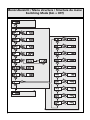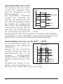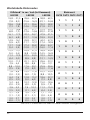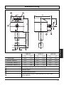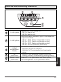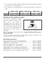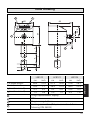
1
Bedienungsanleitung
Operating instructions
Notice pour utilisateurs
R
Elektronischer
Füllstandsensor
Electronic level sensor
ENGLISH
FRANÇAIS
Sachnr. 704047/00
01/2008
LK81
DEUTSCH
Capteur de niveau
électronique
Menü-Übersicht / Menu structure / Structure du menu
Switching Mode (bin = OFF)
M
S
M
S
M
S
M
S
M
M
S
M
M
S
M
M
S
M
M
S
S
M
M
S
M
S
M
M
S
M
M
S
M
M
S
S
M
M
S
M
S
M
S
M
2
M
M
M
M
M
M
M
M
M
M
Menü-Übersicht / Menu structure / Structure du menu
Binary Mode (bin = on)
M
S
M
M
S
M
M
S
M
S
M
M
S
M
M
S
M
S
M
M
DEUTSCH
M
Mode/Enter
Set
M
S
3
Inhalt
Bedien- und Anzeigeelemente . . . . . . . . . . . . . . . . . . . . . . . . . . 5
Bestimmungsgemäße Verwendung . . . . . . . . . . . . . . . . . . . . . . 6
Funktionsbeschreibung . . . . . . . . . . . . . . . . . . . . . . . . . . . . . . . 6
Montage . . . . . . . . . . . . . . . . . . . . . . . . . . . . . . . . . . . . . . . . . . 9
Elektrischer Anschluss . . . . . . . . . . . . . . . . . . . . . . . . . . . . . . . 11
Programmieren . . . . . . . . . . . . . . . . . . . . . . . . . . . . . . . . . . . . 12
Inbetriebnahme / Betrieb . . . . . . . . . . . . . . . . . . . . . . . . . . . . . 19
Technische Daten . . . . . . . . . . . . . . . . . . . . . . . . . . . . . . . . . . . 21
Wertetabelle Binärmodus . . . . . . . . . . . . . . . . . . . . . . . . . . . . . 22
Maßzeichnung . . . . . . . . . . . . . . . . . . . . . . . . . . . . . . . . . . . . 23
Wichtige Hinweise für den Benutzer der Bedienungsanleitung
• Diese Bedienungsanleitung ist Teil des Produkts. Lesen Sie sie vor
der Verwendung des Produkts sorgfältig durch.
• Bewahren Sie die Bedienungsanleitung für den späteren Gebrauch auf.
• Geben Sie die Bedienungsanleitung an nachfolgende Besitzer oder
Benutzer des Produkts weiter.
• Fügen Sie jede Ergänzung, die Sie erhalten, in diese
Bedienungsanleitung ein.
Sicherheitshinweise
• Das Gerät darf nur von einer Elektrofachkraft installiert werden.
• Befolgen Sie die nationalen und internationalen Vorschriften zur
Errichtung elektrotechnischer Anlagen.
• Spannungsversorgung nach EN50178, SELV, PELV.
• Das Gerät entspricht den einschlägigen Vorschriften und EGRichtlinien. Unsachgemäßer oder nicht bestimmungsgemäßer
Gebrauch können jedoch zu Funktionsstörungen des Gerätes oder
zu unerwünschten Auswirkungen in Ihrer Applikation führen.
Deshalb dürfen Montage, elektrischer Anschluss, Inbetriebnahme,
Bedienung und Wartung des Gerätes nur durchgeführt werden
durch ausgebildetes Fachpersonal, das vom Anlagenbetreiber dazu
autorisiert wurde.
• Das
Gerät
entspricht
der
Norm
EN61000-6-4.
In
Haushaltsumgebungen kann das Gerät Rundfunkstörungen verursachen. Sollten Störungen auftreten, muss der Anwender durch
geeignete Maßnahmen für Abhilfe sorgen.
4
Bedien- und Anzeigeelemente
1
2
3
1
2
3
4
5
Set
4
5
2 x LED grün
Leuchtende LED = eingestellte Anzeigeeinheit:
- LED 1 = Anzeige des Füllstands in cm.
- LED 2 = Anzeige des Füllstands in inch.
4 x LED gelb
Anzeige des Schaltzustands; leuchtet, wenn der
jeweilige Ausgang durchgeschaltet ist.
- LED 1 = OUT1 (frei konfigurierbarer Ausgang).
- LED 2 = OUT2 (frei konfigurierbarer Ausgang).
- LED 3 = OUT3 (frei konfigurierbarer Ausgang).
- LED 4 = OUT-OP (Überfüllsicherung).
- Anzeige des aktuellen Füllstands,
4-stellige
alphanumerische - Betriebs- und Fehleranzeigen,
Anzeige
- Anzeige der Parameter und Parameterwerte.
Programmiertaste - Einstellen der Parameterwerte (kontinuierlich durch
Set
Dauerdruck; schrittweise durch Einzeldruck).
Programmiertaste Anwahl der Parameter und Bestätigen der
Mode / Enter
Parameterwerte.
5
DEUTSCH
Mode/Enter
Bestimmungsgemäße Verwendung
Einsatzbereich
Der Füllstandsensor LK81 wurde speziell für die Bedürfnisse des
Werkzeugmaschinenbaus konzipiert. Er ist insbesondere geeignet für
die Überwachung von Kühlschmieremulsionen (auch verschmutzt)
sowie von Kühl- und Hydraulikölen.
Beschränkung des Einsatzbereichs
• Das Gerät ist nicht geeignet für stark leitende und anhaftende
Medien, Granulate, Schüttgüter, Säuren, und Laugen; es ist nicht
geeignet für den Lebensmittel- und Galvanikbereich.
• Das Gerät ist nicht geeignet für den Einsatz in Schleifmaschinen.
• Gut leitfähiger Schaum wird möglicherweise als Füllstand erfasst.
Prüfen Sie die Auswirkungen in Ihrer Applikation.
• Bei Einsatz in wasserbasierten Medien mit Temperaturen > 35°C
muss das Gerät in ein Klimarohr eingebaut werden (Bestell-Nr.
E43100, E43101, E43102).
Funktionsbeschreibung
Messprinzip
Der Sensor ermittelt den Füllstand von Flüssigkeiten nach dem kapazitiven Messprinzip:
• Ein elektrisches Feld wird aufgebaut und beeinflusst durch das zu
erfassende Medium. Diese Feldänderung erzeugt ein Messsignal,
das elektronisch ausgewertet wird.
• Maßgeblich für die Erfassung eines Mediums ist dessen
Dielektrizitätskonstante (DK). Medien mit einem hohen DK-Wert
(z.B. Wasser) erzeugen ein starkes Messsignal, Medien mit einem
niedrigen DK-Wert (z. B. Öle) ein entsprechend geringeres Signal.
• Der aktive Messbereich des Sensorstabes verfügt über 16 kapazitive
Messsegmente. Sie erzeugen jeweils Messsignale, die abhängig
sind vom Bedeckungsgrad.
6
7
DEUTSCH
Funktionsübersicht
• Das Gerät ist in unterschiedlichen Behältergrößen einsetzbar und
flexibel montierbar. Befestigungsvorrichtungen können sich auch
im aktiven Messbereich befinden. Beachten Sie bitte die
Montagehinweise (→ Seite 9).
• Zur Anpassung an verschiedene Medien lassen sich die
Empfindlichkeit und der Erfassungsmodus des Gerätes einstellen.
Damit ist eine sichere Erfassung auch von Medien mit sehr niedrigem DK-Wert (wie z. B. Öl) möglich.
• Eine Abgleichautomatik dient der einfachen und sicheren
Inbetriebnahme. Durch den Abgleich (→ Seite 15) stimmt sich das
Gerät optimal auf den zu überwachenden Behälter ab.
Bitte beachten Sie:
Der Abgleichvorgang ist zwingend erforderlich und dient der
Betriebssicherheit des Füllstandsensors! Ohne Abgleich zeigt das
Display
an, das Gerät geht nicht in den Betriebsmodus!
• Das Gerät besitzt eine integrierte, unabhängig arbeitende Überfüllsicherung. Als Überfüllschaltpunkt OP (= overflow protection
point) wird per Bedienmenü ein Messsegment des Sensorstabs ausgewählt (Messsegment OP) und dem Ausgang OUT-OP zugeordnet. Ansprechzeit für Übervollalarm: Typisch 450 ms, maximal
720 ms.
Das ausgewählte Messsegment wird gleichzeitig zum Abgleich verwendet. Beachten Sie deshalb die erforderlichen Mindestabstände
dieses Segments zu Behälterwand, Behälterdeckel bzw. Einbauadapter (→ Seite 9).
• Das Gerät zeigt den aktuellen Füllstand im Display an und schaltet
die Ausgänge entsprechend der eingestellten Ausgangskonfiguration.
Es bietet 2 Möglichkeiten der Auswertung:
A Schaltmodus (Switching Mode; Voreinstellung ab Werk)
B Binärmodus (Binary Mode)
- A: Im Schaltmodus signalisiert das Gerät das Erreichen oder
Unterschreiten eingestellter Grenzen über die Arbeitsschaltausgänge (OUT1, OUT2, OUT3) und OUT-OP. Schaltfunktion,
Schalt- und Rückschaltpunkt lassen sich über das Bedienmenü einstellen.
- B: Im Binärmodus geben die Ausgänge OUT1 ... OUT4 den
Füllstand im 8-4-2-1-Binärcode aus. Damit steht eine 16-stufige
Quasi-Analogauswertung mit einer Auflösung von maximal
6,25% des Messbereichs zur Verfügung (Wertetabelle → Seite 22).
Auch im Binärmodus muss ein OP-Messsegment festgelegt werden. Es wird allerdings keinem der Ausgänge zugeordnet.
Im Binärmodus werden bei Erreichen von OP alle 4 Ausgänge
durchgeschaltet (auf EINS gesetzt).
Es werden nur dann 16 Auswertestufen erreicht, wenn für OP der
Maximalwert eingestellt ist (oberstes Messsegment = OP). Sitzt OP
tiefer, reduzieren sich die Auswertestufen.
L
OP
Anzeigewert
OP'
OFS
t
OUT1 1
0
OUT2 1
0
OUT3 1
0
OUT4 1
0
A
B
A = Auswertestufen bei OP’ / B = Auswertestufen bei OP
• Der Bereich zwischen Behälterboden und Unterkante des Messstabs
kann als Offset (OFS) eingegeben werden. Dadurch beziehen sich
Anzeige und Schaltpunkte auf den realen Füllstand.
• Wellenbewegungen des Mediums werden geglättet.
8
Montage
M
y
L
OP
B
v
w
x
u
LK8123
cm
inch
47,2
18,6
23
9,1
LK8124
cm
inch
72,8
28,7
36
14,2
• Befestigen Sie Montageelemente innerhalb des Bereichs M.
• Montageelemente müssen oberhalb des Messsegments OP
und in einem Mindestabstand zu OP befestigt werden (siehe Wert
y, gemessen zur Mitte des Segments).
• Der Messstab muss Mindestabstände einhalten zu Behälterwand,
metallischen Objekten im Behälter (B), Behälterboden und weiteren
Füllstandsensoren. Die Abstände x, y und w sind abhängig vom eingestellten Medium (MEDI).
x
y (LK8122)
y (LK8123)
y (LK8124)
u
v
w
MEDI = CLW1
inch
cm
0,8
2,0
1,0
2,5
1,8
4,5
2,4
6,0
0,4
1,0
1,8
4,5
1,6
4,0
MEDI = CLW2, OIL1
inch
cm
1,2
3,0
1,4
3,5
2,2
5,5
2,8
7,0
0,4
1,0
1,8
4,5
2,0
5,0
MEDI = OIL2
inch
cm
1,6
4,0
1,8
4,5
2,6
6,5
3,2
8,0
0,4
1,0
1,8
4,5
2,4
6,0
9
DEUTSCH
L (Stablänge)
M (Montagebereich)
LK8122
cm
inch
26,4
10,4
14
5,5
• Bei Einbau in Kunststoffrohren / Kunststoffbehältern muss der
(Rohr-) / Innendurchmesser mindestens 12 cm (4,8 inch) betragen.
• Bei Einbau in Metallrohren muss der Rohr-Innendurchmesser (d)
mindestens folgenden Wert haben:
d
MEDI = CLW1
cm
inch
4,0
1,6
MEDI = CLW2, OIL1
cm
inch
6,0
2,4
MEDI = OIL2
cm
inch
12,0
4,8
Markieren der Einbauhöhe:
Fixieren Sie die eingestellte
Einbauhöhe mit der beiliegenden
Edelstahl-Schlauchklemme. Wird
der Sensor zu Wartungsarbeiten
aus der Halterung entfernt, dient
die Klemme beim Wiedereinbau
als Anschlag. Ein unabsichtliches
Verstellen des Sensors ist damit
ausgeschlossen. Dies ist insbesondere für die einwandfreie Funktion
der Überfüllsicherung notwendig.
Die Klemme wird mit einer handelsüblichen Beißzange angebracht.
Achten Sie auf einen sicheren Sitz. Zur Demontage muss die Klemme
zerstört werden.
Montagezubehör:
Befestigungsschelle Ø 16 mm, PP (Polypropylen) ............... Bestell-Nr. E43000
Flanschplatte 73 - 90, Aluminium / Edelstahl ..................... Bestell-Nr. E43001
Einschweißmuffe, Edelstahl ............................................... Bestell-Nr. E43002
Einbauadapter G3/4", Edelstahl.......................................... Bestell-Nr. E43003
Einbauadapter G1", Edelstahl............................................. Bestell-Nr. E43004
Flanschplatte 100 - 125, Aluminium / Edelstahl ................. Bestell-Nr. E43005
Flanschplatte 65 - 80, Aluminium / Edelstahl ..................... Bestell-Nr. E43006
Flanschplatte 54 - 52 x 52, Aluminium / Edelstahl ............. Bestell-Nr. E43007
Montageset Ø 16 mm, PP (Polypropylen) / Stahl ................ Bestell-Nr. E43016
10
Elektrischer Anschluss
Das Gerät darf nur von einer Elektrofachkraft installiert werden.
Befolgen Sie die nationalen und internationalen Vorschriften zur
Errichtung elektrotechnischer Anlagen.
Spannungsversorgung nach EN50178, SELV, PELV.
Schalten Sie die Anlage spannungsfrei; schließen Sie das Gerät
folgendermaßen an:
1
7
Pin / Belegung
1
2
3
4
5
6
7
UB+
OUT2 (Arbeitschaltausgang)
UBOUT1 (Arbeitschaltausgang)
OUT3 (Arbeitschaltausgang)
OUT-OP (Überfüllschaltausg.)
nicht belegt
L+
OUT2
L
OUT1
OUT3
OUT-OP/OUT4
n.c.
Adernfarben
bei Kabeldosen nach
bei ifm-Kabeldosen
DIN 47100
braun
weiß
weiß
braun
blau
grün
schwarz
gelb
grau
grau
rosa
rosa
violett
blau
Ausgangsbelegung im Binärmodus: OUT1...4 = Schaltausgänge für QuasiAnalogauswertung.
Steckverbindungen 8-polig auf 4-polig sind als Zubehör lieferbar:
Bestell-Nr. E11228 (Y-Verbindungskabel), Bestell-Nr. E11627 (T-Verteiler)
Zur sicheren Funktion muss das Sensorgehäuse elektrisch mit der
Behälterwand verbunden werden. Verwenden Sie dazu den
Gehäuseanschluss (siehe Maßzeichnung, Seite 23) und ein möglichst
kurzes Kabelstück mit mindestens 1,5 mm2 Adernquerschnitt.
Bei metallischen Behältern fungiert die Behälterwand als Gegenelektrode. Bei
Kunststoffbehältern muss eine Gegenelektrode installiert und mit dem
Sensorgehäuse verbunden werden (z. B. Metallblech im Behälter parallel zum
Sensorstab; Mindestabstand zum Sensorstab: → Seite 9, Abstand x).
11
DEUTSCH
3 2
4
5
6
1
2
3
4
5
6
7
Programmieren
1
Mode/Enter Set
Drücken Sie die Taste Mode/Enter,
bis der gewünschte Parameter
im Display erscheint.
Mode/Enter Set
Drücken Sie die Taste Set und
halten Sie sie gedrückt.
Der aktuelle Parameterwert wird
5 s lang blinkend angezeigt,
2
3
4
Mode/Enter Set
Weitere Parameter verändern:
Beginnen Sie wieder mit Schritt 1.
danach wird er erhöht*
(schrittweise durch Einzeldruck
oder kontinuierlich durch
Festhalten der Taste).
Drücken Sie kurz die Taste
Mode/Enter (= Bestätigung).
Der Parameter wird erneut angezeigt; der neue Parameterwert
ist wirksam.
Programmierung beenden:
Warten Sie 15 s oder drücken Sie
die Mode/Enter-Taste, bis wieder
der aktuelle Messwert erscheint.
*Wert verringern: Lassen Sie die Anzeige bis zum maximalen Einstellwert
laufen. Danach beginnt der Durchlauf wieder beim minimalen Einstellwert.
Timeout: Wird während des Programmiervorgangs 15 s lang keine Taste
gedrückt, geht das Gerät mit unveränderten Werten in den Betriebsmodus
zurück (Ausnahme: cOP).
Verriegeln / Entriegeln: Das Gerät lässt sich elektronisch verriegeln, so dass
unbeabsichtigte Fehleingaben verhindert werden: Drücken Sie im Run-Modus
10 s lang die beiden Programmiertasten ( bis
angezeigt wird). Zum Entriegeln
angezeigt wird).
drücken Sie 10 s lang die Tasten (bis
Auslieferungszustand: Nicht verriegelt.
Bei verriegeltem Gerät erscheint
in der Anzeige, wenn versucht wird, den
Programmiermodus zu öffnen.
Das Gerät kann vor oder nach der Installation programmiert werden.
Ausnahme: Für den Leerabgleich des OP-Segments muss das Gerät im
Behälter eingebaut sein.
12
Führen Sie zur Programmierung die folgenden Schritte in der angegebenen
Reihenfolge durch.
Schritt Programmiervorgang
2
3
4
Erweiterte Funktionen aufrufen
• Taste Mode/Enter drücken, bis EF im Display erscheint.
• Taste Set drücken. Im Display erscheint nun bin, der
erste Parameter des erweiterten Menüs.
• Durch Drücken der Taste Mode/Enter blättern Sie
durch die Parameter
• Durch erneutes Drücken der Taste Set rufen Sie den
zugehörigen Parameterwert auf.
Schaltmodus / Binärmodus auswählen
Auslieferungszustand: Schaltmodus; bin = OFF
Wenn der Auslieferungszustand bestehen bleiben soll,
übergehen Sie diesen Schritt.
Anzeigeeinheit auswählen
Stellen Sie die gewünschte Anzeigeeinheit ein: cm / inch.
Stellen Sie die Anzeigeeinheit ein, bevor Sie die
Schaltgrenzen (SPx, rPx, OP) festlegen. Dadurch vermeiden Sie Rundungsfehler bei der internen Umrechnung
auf die jeweils andere Einheit und erhalten exakt die
gewünschten Werte. Auslieferungszustand: Uni = cm.
Wenn der Auslieferungszustand bestehen bleiben soll,
übergehen Sie diesen Schritt.
Einstellen auf das Medium
Gehen Sie zurück in die Hauptebene des Menüs (durch
mehrfaches Drücken der Taste Mode/Enter).
Stellen Sie die für das Medium passende Empfindlichkeit
und den passenden Erfassungsmodus ein.
Folgende Einstellungen sind wählbar:
• MEDI = CLW1 für Wasser, wasserbasierte Medien,
Kühlschmieremulsionen.
• MEDI = CLW2 für wasserbasierte Medien bei
Temperaturen > 35°C (Betrieb im Klimarohr).
• MEDI = OIL1 für spezielle (z. B. synthetische) Öle oder
Medien mit einer Dielektrizitätskonstante (DK), die
etwas höher ist als die von Mineralölen.
• MEDI = OIL2 für mineralische Öle (DK ≈ 2).
Wählen Sie die Einstellung MEDI = OIL1 auch, wenn das
Medium mit der Einstellung MEDI = OIL2 zwar erkannt
wird, der Sensor aber insgesamt zu empfindlich reagiert.
Stellen Sie im Zweifelsfall die ordnungsgemäße Funktion
durch einen Applikationstest sicher.
DEUTSCH
1
Parameter
13
Schritt Programmiervorgang
5
6
7
8
14
Hinweis: In den Einstellungen CLW1 und CLW2 werden
Anhaftungen (z. B. Metallspäne) unterdrückt. In den
Einstellungen OIL1 und OIL2 wird ein höher dielektrischer Wasser- oder Spänesumpf von einigen Zentimetern
Höhe unterdrückt. Ist keine Ölschicht vorhanden (oder ist
sie sehr dünn), wird der Sumpf detektiert.
Offset einstellen
Der Bereich zwischen Behälterboden und Unterkante des
Messstabes kann als Offset-Wert eingegeben werden.
Dadurch beziehen sich Anzeige und Schaltpunkte auf den
realen Füllstand. Auslieferungszustand: OFS = 0.
Den Einstellbereich OFS finden Sie in der Tabelle auf
Seite 16.
Bitte beachten Sie: Stellen Sie OFS ein, bevor Sie die
Schaltgrenzen (SPx, rPx) und OP einstellen. Dadurch vermeiden Sie versehentliche Fehleinstellungen.
Überfüllschaltpunkt festlegen
Dieser Parameter legt die Position des Überfüllschaltpunktes OP (overflow protection point) fest. Der eingestellte Wert bezieht sich auf die Mitte des Messsegments.
Typischerweise spricht OP bereits an bei Erreichen des OPSegments.
Beachten Sie die Mindestabstände und die Montagevorgaben (→ Seite 9). Den Einstellbereich OP finden Sie in
der Tabelle auf Seite 17. Bitte beachten Sie:
- Stellen Sie OP ein, bevor Sie SPx einstellen. Wird der
OP-Wert nach Einstellen von SPx auf einen Wert ≤
SPx verringert, verschiebt sich der SPx-Wert nach unten.
- OP begrenzt den Messbereich nach oben.
Schaltpunkte festlegen
Legen Sie die Positionen fest für die Schaltpunkte (SPx =
oberer Grenzwert für Füllstand).
Die Einstellbereiche finden Sie in der Tabelle Seite 17.
Rückschaltpunkte festlegen
Rufen Sie wieder die erweiterten Funktionen auf (siehe
Schritt 1, EF).
Legen Sie die Positionen fest für die Rückschaltpunkte
(rPx = unterer Grenzwert für Füllstand).
Die Einstellbereiche finden Sie in der Tabelle Seite 17.
Parameter
Schritt Programmiervorgang
10
11
12
Schaltausgänge konfigurieren
Schaltfunktion für OUT1, OUT2, OUT3 festlegen.
Es sind 4 Einstellungen wählbar: Hysterese- (H..) oder
Fensterfunktion (F..), jeweils als Schließer (.no) oder Öffner (.nc).
Überfüllschaltausgang (OUT-OP) konfigurieren
Es sind zwei Einstellungen wählbar: Hno (Hysterese als
Schließer) und Hnc (Hysterese als Öffner).
Hinweis: Aus Sicherheitsgründen wird für OUT-OP die
Öffnerfunktion (Hnc) empfohlen. Durch das Ruhestromprinzip wird sichergestellt, dass auch Drahtbruch oder
Kabelabriss erkannt werden.
Ausschaltverzögerung für OUT1 einstellen
(z. B. für besonders lange Pumpzyklen).
Einstellbereich: 0...5 s in Schritten von 0,2 s.
dr1 ist nur aktiv, wenn OU1 = Hno oder Hnc.
Leerabgleich des OP-Segments
Gehen Sie zurück in die Hauptebene des Menüs (durch
mehrfaches Drücken der Taste Mode/Enter).
Führen Sie nach der Montage des Gerätes an seinem vorgesehen Einbauort einen Leerabgleich des OP-Segments
durch. Der Behälter darf hierbei teilweise befüllt sein. Das
OP-Segment darf beim Abgleichvorgang jedoch nicht
vom Medium bedeckt sein, andernfalls kann es zu
Fehlfunktionen kommen. Mindestabstand zwischen OP
und Medium beim Abgleich:
• LK8122: 2,0 cm / 0,8 inch
• LK8123: 3,5 cm / 1,4 inch
• LK8124: 5,0 cm / 2,0 inch
Abgleichvorgang
• Taste Mode/Enter drücken, bis cOP im Display
erscheint.
• Taste Set drücken und festhalten.
erscheint blinkend im Display. Taste loslassen, wenn Anzeige nicht
mehr blinkt.
• Ist der Abgleich erfolgreich, wird rdy angezeigt.
Druck auf Taste Mode/Enter führt zurück zum Menü.
Während des Abgleichs überprüft das Gerät die
Einbausituation durch Auswertung des Messsignals, das
vom OP-Element erzeugt wird. Liegt das Messsignal im
DEUTSCH
9
Parameter
15
Schritt Programmiervorgang
Parameter
ungültigen Bereich (wenn z. B. ein MontageMindestabstand unterschritten wird), erscheint im Display
eine Fehlermeldung (→ Seite 19, Betriebs- und Fehleranzeigen).
Wenn sich der OP-Abgleich nicht durchführen lässt, überprüfen Sie bitte die Lage des OP. Möglicherweise liegt der
OP zu nahe am Einbauadapter oder anderen metallischen
Objekten oder der OP ist vom Medium bedeckt.
Bei sehr vollen Behältern kann es notwendig sein, den
Behälter etwas zu entleeren oder (wenn möglich) den OPWert zu erhöhen.
Der Sensor lässt sich erst nach dem Leerabgleich in Betrieb nehmen.
Wird er nicht durchgeführt, geht das Gerät nicht in den Betriebsmodus,
das Display zeigt
an.
Ein OP-Abgleich muss jedesmal durchgeführt werden, wenn sensible
Parameter verändert wurden (Einstellung auf das Medium, OP-Wert).
Erkennt das Gerät relevante Veränderungen, erscheint
im Display.
Wird die Einbaulage (Höhe, Position) oder die Verbindung SensorBehältermasse (z.B. Länge des Verbindungskabels) verändert, ist ebenfalls ein erneuter OP-Abgleich zwingend notwendig, um eine einwandfreie Funktion der Überfüllsicherung zu gewährleisten.
Achtung: Der Leerabgleich wird in diesem Fall nicht durch Anzeige von
angefordert!
In den folgenden Tabellen finden Sie die Einstellbereiche für OFS, die
Einstellbereiche für SPx und rPx und die Einstellwerte für OP.
Bitte beachten Sie: Die OP-, SPx- rPx-Werte der Tabellen gelten für OFS
= 0; bei OFS > 0 erhöhen sie sich um den eingestellten OFS-Wert.
Einstellbereiche für OFS
LK8122
cm
inch
Einstellbereich
0...78 0...30,8
Schrittweite
0,5
0,2
16
LK8123
cm
inch
0...57 0...22,4
0,5
0,2
LK8124
cm
inch
0...186 0...73
1
0,5
Einstellwerte für OP
LK8122
cm
6,9
8,2
9,4
10,6
11,8
13,0
14,3
15,5
16,7
17,9
19,1
20,4
LK8123
inch
2,7
3,2
3,7
4,2
4,7
5,1
5,6
6,1
6,6
7,1
7,5
8,0
cm
13,9
16,3
18,8
21,2
23,6
26,1
28,5
31,0
33,4
35,8
38,3
40,7
LK8124
inch
5,5
6,4
7,4
8,3
9,3
10,3
11,2
12,2
13,1
14,1
15,1
16,0
cm
20
24
28
31
35
39
42
46
50
53
57
61
inch
8,0
9,5
10,9
12,3
13,8
15,2
16,7
18,1
19,5
21,0
22,4
23,9
Einstellbereiche für SPx, rPx
LK8123
cm
inch
4,0...39,0 1,6...15,4
3,5...38,5 1,4...15,2
0,5
0,2
LK8124
cm
inch
6...58
2,5...23,0
5...57
2,0...22,5
1
0,5
*ΔL = Schrittweite
• rPx ist stets kleiner als SPx, SPx ist stets kleiner als OP.
Wird der Wert für OP auf einen Wert ≤ SPx verringert, verschiebt sich auch
die Position von SPx. Wird der Wert für SPx auf einen Wert ≤ rPx verringert,
verschiebt sich auch die Position von rPx.
• Liegen rPx und SPx eng beieinander (ca. 3 x Schrittweite), wird rPx bei
Erhöhen von SPx mitgezogen.
• Liegen rPx und SPx weiter auseinander, bleibt rPx auf dem eingestellten
Wert, auch wenn SPx erhöht wird.
17
DEUTSCH
SPx
rPx
ΔL*
LK8122
cm
inch
2,5...19,0 1,0...7,4
2,0...18,5 0,8...7,2
0,5
0,2
Hysteresefunktion (Hno, Hnc):
Die Hysterese hält den SchaltL
zustand des Ausgangs stabil,
wenn der Prozesswert um den
SP
Sollwert schwankt.
Hysterese
rP
Bei steigendem Prozesswert
schaltet der Ausgang bei
Erreichen des Schaltpunkts (OP /
t
1
SPx). Fällt der Prozesswert wieder
0
Hno
ab, schaltet der Ausgang erst
1
Hnc
dann zurück, wenn die Hysterese
0
unterschritten wird (bei OUT-OP)
L = Füllstand
oder wenn der Rückschaltpunkt
rPx unterschritten wird (bei OUT1 ... OUT3).
Die Hysterese für OP ist fest eingestellt. Sie beträgt einige Millimeter.
Die Hysterese für SPx ist einstellbar: Zuerst wird der Schaltpunkt festgelegt, dann im gewünschten Abstand der Rückschaltpunkt.
Fensterfunktion (Fno, Fnc; nur für OUT1 ... OUT3):
Die Fensterfunktion erlaubt die
Gutbereich
Überwachung eines definierten
L
Gutbereichs.
SP
Bewegt sich der Prozesswert
zwischen Schaltpunkt (SPx) und
rP
Rückschaltpunkt (rPx), ist der
Ausgang
durchgeschaltet
(Fensterfunktion / Schließer) bzw.
1
0
geöffnet (Fensterfunktion / Öff1
ner).
0
Die Breite des Fensters ist einL = Füllstand
stellbar durch den Abstand von
SPx zu rPx. SPx = oberer Wert, rPx= unterer Wert.
18
t
Fno
Fnc
Inbetriebnahme / Betrieb
Prüfen Sie nach Montage, elektrischem Anschluss
Programmierung, ob das Gerät sicher funktioniert.
und
Betriebs- und Fehleranzeigen:
CAL
XX.X
FULL
XX.X
Initialisierung nach dem Einschalten.
Anzeige des Füllstands.
Füllstand unterhalb des aktiven Bereichs.
Überfüllschaltpunkt OP ist erreicht.
“FULL” und die Anzeige des aktuellen Füllstands wechseln im
Sekundentakt (= Warnanzeige Überfüllung).
Abgleich des OP-Segments erforderlich (→ Seite 15, cOP).
Err5
Fehler beim OP-Abgleich: Montageelement unterhalb des OPSegments erkannt. Beachten Sie die Montagehinweise und die
angegebenen Mindestabstände, (→ Seite 9).
Err6
Fehler beim Abgleich: Messwert nicht konstant.
DEUTSCH
Err0, Err2,
Fehler in der Elektronik (das Gerät muss ersetzt werden).
Err7, Err8
- OP-Segment verschmutzt (reinigen Sie den Messstab und
Err1
führen Sie ein Reset durch) oder
- OP-Segment defekt (das Gerät muss ersetzt werden).
Betriebssicherheit nicht gewährleistet (Störquellen, schlechte
Err3
Zuleitungen). Überprüfen Sie den elektrischen Anschluss, die
Verbindung Sensor- Behältermasse (→ Seite 11), und die
Einbaubedingungen (→ Seite 9).
Fehler beim OP-Abgleich: Abstand OP-Segment zu MontageErr4
elementen oder zum Medium zu gering. Beachten Sie die
Montagehinweise und die angegebenen Mindestabstände,
(→ Seite 9 / 15).
SC1...SC4 Blinkend: Kurzschluss Schaltausgang 1...4.
Reset (Zurücksetzen der Fehlermeldungen): OP-Abgleich erneut durchführen
oder Versorgungsspannung abschalten und wieder einschalten.
19
Einstellung der Parameter ablesen:
• Kurzer Druck auf die Taste “Mode/Enter” blättert durch die
Parameter.
• Kurzer Druck auf die Taste “Set” zeigt jeweils 15 s lang den
zugehörigen Parameterwert ohne ihn zu verändern.
Ausgangsverhalten in verschiedenen Betriebszuständen
Initialisierung
OP-Abgleich nicht durchgeführt
OP-Abgleich durchgeführt
Fehlerfall (Schaltmodus)
Fehlerfall (Binärmodus)
OUT1...OUT3
OUT-OP
AUS
AUS
AUS
AUS
gemäß Füllstand und gemäß Füllstand und
Einstellung OUx
Einstellung OU4
AUS
AUS
EIN
EIN
Wartung/Reinigung/Medienwechsel
• Beachten Sie, wenn das Gerät zu Wartungs- und Reinigungsarbeiten
aus dem Behälter ausgebaut wurde: Beim Wiedereinbau muss es
exakt in der gleichen Position und Einbauhöhe wie zuvor montiert
werden. Fixieren Sie vor dem Ausbau die eingestellte Einbauhöhe
mit der beiliegenden Edelstahl-Schlauchklemme (→ Seite 10).
• Wird die Verbindung Sensor-Behältermasse geändert, muss ein
erneuter OP-Abgleich durchgeführt werden (→ Seite 15).
• Nach dem Wechsel von Medien mit stark unterschiedlichen
Dielektrizitätskonstanten (z. B. Öl / Wasser) muss das Gerät auf das
neue Medium eingestellt und neu abgeglichen werden (→ Seite 13,
MEDI und Seite 15, cOP).
• Halten Sie den Sensorstab frei von Ablagerungen, insbesondere den
Bereich der Überfüllsicherung (OP-Segment). Ablagerungen in diesem Bereich können zu fehlerhaftem Ansprechen der Überfüllsicherung führen.
20
Betriebsspannung [V] . . . . . . . . . . . . . . . . . . . . . . . . . . . . . . 18 ... 30 DC
Strombelastbarkeit [mA] . . . . . . . . . . . . . . . . . . . . . . . . . . . . . . . . . . 200
Kurzschlussschutz, getaktet; verpolungssicher / überlastfest
Spannungsabfall [V] . . . . . . . . . . . . . . . . . . . . . . . . . . . . . . . . . . . . < 2,5
Stromaufnahme [mA] . . . . . . . . . . . . . . . . . . . . . . . . . . . . . . . . . . . . < 60
Schaltpunktgenauigkeit [% vom Messbereichsendwert] . . . . . . . . . . . . ± 5
Wiederholgenauigkeit [% vom Messbereichsendwert] . . . . . . . . . . . . . ± 2
Max. Geschwindigkeit der Füllstandsänderung [mm/s]
- LK8122 . . . . . . . . . . . . . . . . . . . . . . . . . . . . . . . . . . . . . . . . . . . . . 100
- LK8123 . . . . . . . . . . . . . . . . . . . . . . . . . . . . . . . . . . . . . . . . . . . . . 200
- LK8124 . . . . . . . . . . . . . . . . . . . . . . . . . . . . . . . . . . . . . . . . . . . . . 300
DK - Medium . . . . . . . . . . . . . . . . . . . . . . . . . . . . . . . . . . . . . . . . . . > 2
Max. Behälterdruck [bar] (bei Einbau mit ifm-Montagezubehör) . . . . . . 0,5
Gehäusewerkstoffe . . . . V2A (1.4301); FKM; NBR; PBT; PC; PEI; PP; TPE / V
Werkstoffe in Kontakt mit dem Medium . . . . . . . . . . . . . . . . . . . . . . . .PP
Schutzart, Schutzklasse . . . . . . . . . . . . . . . . . . . . . . . . . . . . . . . . .IP 67, III
Umgebungstemperatur [°C] . . . . . . . . . . . . . . . . . . . . . . . . . . . . . .0 ... 60
Mediumtemperatur
- Öl (Dauer / Kurzzeit) [°C] . . . . . . . . . . . . . . . . . . . . . . . . . . 0...70 / 0...90
- Wasserbasierte Kühlschmiermittel, Wasser und wasserähnliche Medien*
- LK8122 [°C] . . . . . . . . . . . . . . . . . . . . . . . . . . . . . . . . . . . . . . 0 ... 65
- LK8123 [°C] . . . . . . . . . . . . . . . . . . . . . . . . . . . . . . . . . . . . . . 0 ... 60
- LK8124 [°C] . . . . . . . . . . . . . . . . . . . . . . . . . . . . . . . . . . . . . . 0 ... 55
Lagertemperatur [°C] . . . . . . . . . . . . . . . . . . . . . . . . . . . . . . . . .-25 ... 80
Schockfestigkeit [g] . . . . . . . . . . . . . . . . . 15 (DIN EN 60068-2-29, 11 ms)
Vibrationsfestigkeit [g] . . . . . . . . . . . . 5 (DIN EN 60068-2-6, 10...2000 Hz)
EMV
EN 61000/4/2 ESD: . . . . . . . . . . . . . . . . . . . . . . . . . . . . . . . . . . . . . 4/8kV
EN 61000/4/3 HF gestrahlt: . . . . . . . . . . . . . . . . . . . . . . . . . . . . . . 10V/m
EN 61000/4/4 Burst: . . . . . . . . . . . . . . . . . . . . . . . . . . . . . . . . . . . . . 2kV
EN 61000/4/6 HF leitungsgebunden: . . . . . . . . . . . . . . . . . . . . . . . . . 10V
*Bei Einsatz in Wasser und wasserbasierten Medien mit Temperatur > 35° C
muss das Gerät in ein Klimarohr eingebaut werden (Bestell-Nr. E43100,
E43101, E43102).
21
DEUTSCH
Technische Daten
Wertetabelle Binärmodus
Füllstand* in cm / inch (in Klammern)
LK8122
LK8123
LK8124
19,8 ... 21,0
39,6 ... 42,0
(7,8 ... 8,2)
(15,6 ... 16,5)
18,6 ... 19,8
37,1 ... 39,6
(7,3 ... 7,8)
(14,6 ... 15,6)
17,3 ... 18,6
34,7 ... 37,1
(6,8 ... 7,3)
(13,6 ... 14,6)
16,1 ... 17,3
32,3 ... 34,7
(6,3 ... 6,8)
(12,7 ... 13,6)
14,9 ... 16,1
29,8 ... 32,3
(5,9 ... 6,3)
(11,7 ... 12,7)
13,7 ... 14,9
27,4 ... 29,8
(5,4 ... 5,9)
(10,8 ... 11,7)
12,5 ... 13,7
24,9 ... 27,4
(5,0 ... 5,4)
(9,8 ... 10,8)
11,3 ... 12,5
22,5 ... 24,9
(4,4 ... 5,0)
(8,9 ... 9,8)
10,0 ... 11,3
20,1 ... 22,5
3,9 ... 4,4
8,0 ... 8,9
8,8 ... 10,0
17,6 ... 20,1
(3,5 ... 3,9)
(7,0 ... 8,0)
7,6 ... 8,8
15,2 ... 17,6
(3,0 ... 3,5)
(6,0 ... 7,0)
6,4 ... 7,6
12,8 ... 15,2
(2,5 ... 3,0)
(5,0 ... 6,0)
5,2 ... 6,4
10,3 ... 12,8
(2,0 ... 2,5)
(4,0 ... 5,0)
3,9 ... 5,2
7,9 ... 10,3
(1,5 ... 2,0)
(3,1 ... 4,0)
2,7 ... 3,9
5,4 ... 7,9
(1,1 ... 1,5)
(2,1 ... 3,1)
0,0 ... 2,7
0,0 ... 5,4
(0,0 ... 1,1)
(0,0 ... 2,1)
*Bei OFS > 0 wird
22
Binärwert
OUT4 OUT3 OUT2 OUT1
58,8 ... 62,5
1
1
1
1
(23,1 ... 24,6)
55,2 ... 58,8
1
1
1
0
(21,8 ... 23,1)
51,5 ... 55,2
1
1
0
1
(20,2 ... 21,8)
47,9 ... 51,5
1
1
0
0
(18,9 ... 20,2)
44,2 ... 47,9
1
0
1
1
(17,4 ... 18,9)
40,6 ... 44,2
1
0
1
0
(16,0 ... 17,4)
36,9 ... 40,6
1
0
0
1
(14,5 ... 16,0)
33,3 ... 36,9
1
0
0
0
(13,1 ... 14,5)
29,6 ... 33,3
0
1
1
1
11,6 ... 13,1
25,9 ... 29,6
0
1
1
0
(10,2 ... 11,6)
22,3 ... 25,9
0
1
0
1
(8,8 ... 10,2)
18,6 ... 22,3
0
1
0
0
(7,3 ... 8,8)
15,0 ... 18,6
0
0
1
1
(5,9 ... 7,3)
11,3 ... 15,0
0
0
1
0
(4,4 ... 5,9)
7,7 ... 11,3
0
0
0
1
(3,0 ... 4,4)
0,0 ... 7,7
0
0
0
0
(0,0 ... 3,0)
der OFS-Wert zu diesen Werten hinzugezählt.
Maßzeichnung
2
3
50
4
16
L (Stablänge)
A (aktiver Bereich)
I1 (inaktiver Bereich 1)
I2 (inaktiver Bereich 2)
1
2
3
4
LK8122
cm
inch
26,4
10,4
19,5
7,7
5,3
2,0
1,5
0,6
LK8123
cm
inch
47,2
18,6
39,0
15,4
5,3
2,0
3,0
1,2
LK8124
cm
inch
72,8
28,7
58,5
23,0
10,2
4,0
4,0
1,6
4-stellige alphanumerische Anzeige
Status-LEDs
Programmiertasten
Gehäuseanschluss (Flachstecker 6,3 mm nach
DIN 46244)
23
DEUTSCH
I2
A
L
I1
1
3
57
M12 x1
30,5
64
Contents
Controls and indicating elements .
Function and features . . . . . . . . .
Functional overview . . . . . . . . . .
Mounting . . . . . . . . . . . . . . . . . .
Electrical connection . . . . . . . . . .
Programming . . . . . . . . . . . . . . .
Installation and set-up / Operation
Technical data . . . . . . . . . . . . . . .
Table of binary values . . . . . . . . . .
Scale drawing . . . . . . . . . . . . . . .
.
.
.
.
.
.
.
.
.
.
.
.
.
.
.
.
.
.
.
.
.
.
.
.
.
.
.
.
.
.
.
.
.
.
.
.
.
.
.
.
.
.
.
.
.
.
.
.
.
.
.
.
.
.
.
.
.
.
.
.
.
.
.
.
.
.
.
.
.
.
.
.
.
.
.
.
.
.
.
.
.
.
.
.
.
.
.
.
.
.
.
.
.
.
.
.
.
.
.
.
.
.
.
.
.
.
.
.
.
.
.
.
.
.
.
.
.
.
.
.
.
.
.
.
.
.
.
.
.
.
.
.
.
.
.
.
.
.
.
.
.
.
.
.
.
.
.
.
.
.
.
.
.
.
.
.
.
.
.
.
.
.
.
.
.
.
.
.
.
.
.
.
.
.
.
.
.
.
.
.
.
.
.
.
.
.
.
.
.
.
.
.
.
.
.
.
.
.
.
.
.
.
.
.
.
.
.
.
.
.
.
.
.
.
.
.
.
.
.
.
25
26
26
29
31
32
39
41
42
43
Important notes for the user of these instructions
• These operating instructions are a part of the product. Carefully
read them before using the product.
• Keep the operating instructions for later use.
• Pass the operating instructions on to future owners or users of the
product.
• Whenever you receive a supplement to these operating instructions
enclose it to them.
Safety instructions
• The unit must be connected by a suitably qualified electrician.
• The national and international regulations for the installation of
electrical equipment must be observed.
• Voltage supply according to EN50178, SELV, PELV.
• The unit conforms to the relevant regulations and EU directives.
Improper use or non-intended use may lead to malfunctions of the
unit or to unwanted effects in your application.
That is why installation, electrical connection, set-up, operation and
maintenance of the unit must only be carried out by qualified personnel authorised by the machine operator.
• The unit conforms to the standard EN 6100-6-4. The unit may
cause radio interference in domestic areas. If interference occur, the
user must take appropriate remedial actions.
24
Controls and indicating elements
1
2
3
Set
4
5
2 x LED green
Lighting LED = set display unit:
- LED 1 = level in cm.
- LED 2 = level in inch.
2
4 x LED yellow
Switching status indication; lights if the respective
output is switched.
- LED 1 = OUT1 (freely configurable output).
- LED 2 = OUT2 (freely configurable output).
- LED 3 = OUT3 (freely configurable output).
- LED 4 = OUT-OP (overflow protection).
3
4-digit
alphanumeric
display
- Indication of the current level.
- Operating and fault indication.
- Indication of the parameters and parameter
values.
Set
pushbutton
Mode / Enter
pushbutton
- Setting of the parameter values (scrolling by
holding pressed; incremental by pressing briefly).
Selection of the parameters and menu points,
acknowledgement of the parameter values.
1
4
5
ENGLISH
Mode/Enter
25
Function and features
Applications
The level sensor LK81 was specially designed to meet the requirements of machine tool building. It is specially suitable for monitoring
coolant emulsions (also dirty) as well as cutting and hydraulic oils.
Restriction of the application area
• The sensor is not suitable for extremely conductive and adhering
media, granulates and bulk materials, acids and alkalis. It is not suitable for food and electroplating applications.
• The sensor is not suitable for use in grinders.
• It is possible that foam of good conductivity is detected as level.
Check the effects in your application.
• For water and hydrous media with temperatures > 35°C the unit
must be mounted into a climatic tube (order no. E43100, E43101,
E43102).
Functional overview
Measuring principle
The sensor determines the level of fluids according to the capacitive
measuring principle:
• An electrical field is generated and influenced by the medium to be
detected. This change to the field causes a measurement signal that
is electronically evaluated.
• The dielectric constant of a medium is important for its detection.
Media with a high dielectric constant (e.g. water) generate a strong
measurement signal, media with a low dielectric constant (e.g. oils)
a correspondingly lower signal.
• The active measurement zone of the sensor probe is composed of
16 capacitive measuring segments. They generate measurement
signals depending on the degree of coverage.
26
The sensor offers 2 evaluation modes:
A Switching mode (factory preset)
B Binary mode
- A: In the switching mode the unit signals values that exceed or
do not reach the limit values set via the operating switching
outputs (OUT1, OUT2, OUT3) and OUT-OP. The switching function,
switch point and reset point can be set via the user menu.
- B: In the binary mode the outputs OUT1 ... OUT4 indicate the
level as a 8-4-2-1 binary code. Thus a 16-step quasi-analogue
evaluation with a resolution of max. 6.25% of the measuring
range is available (table of values → page 42).
27
ENGLISH
Functional overview
• The unit can be installed in tanks of different sizes. Mounting elements may also be placed in the active measurement zone. Please
adhere to the mounting instructions (→ page 29).
• The sensitivity and the mode of detection of the unit can be set in
order to adjust to different media. This allows the reliable detection
of media with a very low dielectric constant (e.g. oil).
• The automatic adjustment serves for easy and secure set-up. By
means of the adjustment operation (→ page 35) the unit can be
adjusted to the tank being monitored.
Please note:
The adjustment operation is compulsory to ensure the reliable operation of the level sensor! Without adjustment,
is displayed and
the unit will not change into the operating mode!
• The unit features an integrated, independent overflow
protection. A measuring segment of the sensor probe (measuring
segment OP) is selected as overflow protection point OP via the
user menu and assigned to the output OUT-OP. The response time
for the overflow alarm: typ. 450 ms, max. 720 ms.
The selected measuring segment is at the same time used for
adjustment. Therefore, please adhere to the required minimum distances of this segment to the tank wall, tank cover and mounting
adapter (→ page 29).
• The unit displays the current level and switches the outputs in
accordance with the set output configuration
A measuring segment OP also has to be determined in the binary
mode. However, it is not assigned to any of the outputs.
In the binary mode all 4 outputs are switched (set to ONE) when OP
is reached.
16 evaluation steps are only achieved when the maximum value is
set for OP (highest measuring segment = OP). The evaluation steps
are reduced if OP is lower.
L
OP
display
value
OP'
OFS
t
OUT1 1
0
OUT2 1
0
OUT3 1
0
OUT4 1
0
A
B
A = evaluation steps for OP' / B = evaluation steps for OP
• The zone between tank bottom and lower edge of the measuring
probe can be entered as offset value (OFS). Thus display and switch
points refer to the real level.
• Wave movements of the medium are smoothed.
28
Mounting
M
y
L
OP
B
v
w
x
u
L (probe length)
M (mounting zone)
LK8122
cm
inch
26.4
10.4
14
5.5
LK8123
cm
inch
47.2
18.6
23
9.1
LK8124
cm
inch
72.8
28.7
36
14.2
• Fasten mounting elements within zone M.
• Mounting elements must be fixed above the measuring segment
OP and at a minimum distance to OP (see value y, measured to the
middle of the segment).
• The probe must comply with minimum distances to the tank wall,
metallic objects in the tank (B), tank bottom and further level sensors. The distances x, y and w depend on the medium set (MEDI).
MEDI = CLW2, OIL1
inch
cm
1.2
3.0
1.4
3.5
2.2
5.5
2.8
7.0
0.4
1.0
1.8
4.5
2.0
5.0
MEDI = OIL2
inch
cm
1.6
4.0
1.8
4.5
2.6
6.5
3.2
8.0
0.4
1.0
1.8
4.5
2.4
6.0
ENGLISH
x
y (LK8122)
y (LK8123)
y (LK8124)
u
v
w
MEDI = CLW1
inch
cm
0.8
2.0
1.0
2.5
1.8
4.5
2.4
6.0
0.4
1.0
1.8
4.5
1.6
4.0
29
• For mounting in plastic pipes / plastic tanks the inside (pipe) diameter
must be min. 12 cm (4.8 inch).
• For mounting in metal pipes the inside pipe diameter must be at
least:
Diameter
MEDI = CLW1
cm
inch
4.0
1.6
MEDI = CLW2, OIL1
cm
inch
6.0
2.4
MEDI = OIL2
cm
inch
12.0
4.8
Marking of the installation height:
Fix the set installation height
with the supplied stainless steel
tube clip. If the sensor is
removed from the fixture for
maintenance the clip serves as a
limit stop when remounting the
sensor. Thus an inadvertent maladjustment of the sensor is
excluded.
This is in particular necessary for the correct function of the overflow protection.
The clip is fitted using common nipper pliers. Ensure a correct fit. To
remove the clip, it must be destroyed.
Mounting accessories:
Mounting clamp Ø 16 mm, PP (polypropylene) .................. order no. E43000
Flange plate 73 - 90, aluminum / stainless steel ................. order no. E43001
Welding bush, stainless steel .............................................. order no. E43002
Mounting adapter G3/4", stainless steel.............................. order no. E43003
Mounting adapter G1", stainless steel................................. order no. E43004
Flange plate 100 - 125, aluminum / stainless steel ............. order no. E43005
Flange plate 65 - 80, aluminum / stainless steel ................. order no. E43006
Flange plate 54 - 52 x 52, aluminum / stainless steel .......... order no. E43007
Mounting set Ø 16 mm, PP (polypropylene) / steel .............. order no. E43016
30
Electrical connection
The unit must be connected by a suitably qualified electrician.
The national and international regulations for the installation of
electrical equipment must be observed.
Voltage supply according to EN50178, SELV, PELV.
Disconnect power before connecting the unit as follows:
1
7
Pin / connection
1
2
3
4
5
6
7
UB+
OUT2 (operating output)
UBOUT1 (operating output)
OUT3 (operating output)
OUT-OP (overflow output)
not connected
L+
OUT2
L
OUT1
OUT3
OUT-OP/OUT4
n.c.
core colours
sockets following
ifm sockets
DIN 47100
brown
white
white
brown
blue
green
black
yellow
grey
grey
pink
pink
lilac
blue
Output configuration in binary mode: OUT1...4 = Switching outputs for
quasi-analogue evaluation.
Connector 8-pole on connector 4-pole are available as accessories
order no. E11228 (Y connection cable), order no. E11627 (T-Splitter box).
For safe function the sensor housing must be electrically connected to
the vessel wall. To do so, use the housing connection with the blue
cable lug (see scale drawing) and a cable piece with a wire crosssection of min. 1.5 mm2 that is as short as possible.
When using metal tanks the tank wall serves as the machine earth. When using
plastic tanks an electrode has to be installed and connected to the sensor housing (e.g. sheet metal in the tank in parallel with the probe; min. distance to
the probe: → page 29, distance x).
31
ENGLISH
3 2
4
5
6
1
2
3
4
5
6
7
Programming
1
Mode/Enter Set
Press the Mode/Enter button
several times until the respective
parameter is displayed.
Mode/Enter Set
Press the Set button and keep
it pressed. The current parameter
value flashes for 5 s,
2
then the value is increased*
(incremental by pressing briefly or
scrolling by holding pressed).
3
4
Mode/Enter Set
Change more parameters:
Start again with step 1.
Press the Mode/Enter button
briefly (= acknowledgement).
The parameter is displayed again,
the set parameter value
becomes effective.
Finish programming:
Wait for 15 s or press the
Mode/Enter button until the current
measured value is indicated again.
*Decrease the value: Let the display of the parameter value move to the
maximum setting value. Then the cycle starts again at the minimum setting
value.
Timeout: If no button is pressed for 15 s during the setting procedure, the unit
returns to the Run mode with unchanged values (exception: cOP).
Locking / Unlocking: The unit can be electronically locked to prevent unwanted adjustment of the set parameters: Press both pushbuttons for 10 s (until
is displayed). To unlock: Press both pushbuttons for 10 s (until
is
displayed).
Units are delivered from the factory in the unlocked state.
With the unit in the locked state
is indicated when you try to change
parameter values.
The sensor can be programmed before or after mounting. Exception: For the
adjustment of the measuring element OP the unit must be installed in the tank.
For programming carry out the following steps in the indicated order.
32
1
2
3
4
Programming
Parameter
Access the extended functions
• Press the Mode/Enter button until EF is displayed.
• Press the Set button. bin is now displayed, the first
parameter of the extended menu.
• You can scroll through the parameters by pressing the
Mode/Enter button.
• You can access the corresponding parameter value by
again pressing the Set button.
Select Switching mode / Binary mode
Factory setting: Switching mode; bin = OFF
Please skip this step if you want to maintain the factory
setting.
Selection of the display unit
Set the required display unit: cm / inch.
Select the display unit before setting values for the parameters (SPx, rPx, OP). This avoids rounding errors generated internally during the conversion of the units and
enables exact setting of the values.
Setting at the factory: Uni = cm.
Please skip this step if you want to maintain the factory
setting.
Setting to the medium
Return to the main level of the menu (by repeatedly
pressing the Mode/Enter button).
Set the appropriate sensitivity for the medium and the
appropriate mode of detection.
The following settings can be chosen:
• MEDI = CLW1 for water, coolant emulsions, hydrous
media.
• MEDI = CLW2 for hydrous media with temperatures
> 35°C (mounted in the climatic tube).
• MEDI = OIL1 for special (e.g. synthetic) oils or media
with a dielectric constant that is a little higher than
that of mineral oils.
• MEDI = OIL2 for mineral oils (DK ≈ 2).
Also select the setting MEDI = OIL1 if the medium is
detected with MEDI = OIL2 but on the whole the sensor
sensitivity is too high. In case of doubt ensure the correct
function by performing a test in your application.
ENGLISH
Step
33
Step
5
6
7
8
34
Programming
Note: If CLW1 or CLW2 are selected build-up (e.g. metal
swarf) is suppressed. If OIL1 or OIL2 are selected, a bottom layer of higher dielectric water or swarf which is a
few cm high is suppressed. If no oil layer is present (or if
it is very thin), the bottom layer is detected.
Setting of the offset value
The zone between tank bottom and lower edge of the
measuring probe can be entered as offset value (OFS).
Thus display and switch points refer to the real level.
Setting at the factory: OFS = 0.
The setting values OFS are indicated in the table on page
36.
Please note: Select OFS, before setting values for the
parameters SPx, rPx and OP. This avoids inadvertent
maladjustment.
Setting of the overflow protection point
This parameter defines the position of the overflow protection point OP. The set value refers to the middle of the
measuring segment. Typically, OP already reacts when the
OP segment is reached.
Please adhere to the minimum distances and mounting
instructions (→ page 29). For the setting range of OP
please refer to the table on page 37.
Please note:
- Set OP before setting SPx. If the OP value is reduced to
a value ≤ after switch point setting, the SPx value shifts
downward.
- OP is the maximum limit of the measuring range.
Setting of the switch points
Define the positions for the switch points (SPx = upper
limit level value).
For the setting ranges please refer to the table on page
37.
Setting of the reset points
Access the extended functions (see step 1, EF).
Define the positions for the reset points (rPx = lower limit
level value).
For the setting ranges please refer to the table on page
37.
Parameter
9
10
11
12
Programming
Parameter
Configuration of the switching outputs
(setting of the switching functions for OUT1, OUT2, OUT3.
4 settings can be selected: hysteresis- (H..) or window
function (F..), as normally open (.no) or normally closed
(.nc).
Configuration of the overflow output (OUT-OP
2 settings can be selected: Hno (hysteresis function as
normally open) and Hnc (hysteresis function as normally
closed).
Note: For safety reasons the normally closed function
(Hnc) is recommended for OU4. The principle of normally
closed operation ensures that wire break or cable break
are detected.
Setting the Switch-off delay for OUT1
(for example for specially long pump cycles).
setting range: 0 ... 5 s in steps of 0.2s.
dr1 is active only if OU1 = Hno or Hnc.
Empty adjustment of the OP segment
Return to the main level of the menu (by repeatedly
pressing the Mode/Enter button).
Carry out an empty adjustment of the OP segment after
mounting of the unit at the intended mounting location.
The tank may be partly filled. During the adjustment
operation, the OP segment must however not be covered
by the medium, otherwise malfunctions may occur.
Minimum distance between OP and the medium during
adjustment:
• LK8122: 2.0 cm / 0.8 inch
• LK8123: 3.5 cm / 1.4 inch
• LK8124: 5.0 cm / 2.0 inch
Adjustment operation:
• Press the Mode/Enter button until cOP is displayed.
• Press the Set button and keep it pressed.
is indicated (flashing). Release the button when the display
stops flashing.
• If adjustment is successful, rdy is indicated. Return to
the menu by pressing the Mode/Enter button.
During the adjustment the unit checks the installation
conditions by evaluating the measured signal generated
by the OP element. If the measured signal is invalid (if for
ENGLISH
Step
35
Step
Programming
Parameter
example the mounting situation is below the minimum
distance), an error message is displayed (→ page 39,
operating and error messages).
When an OP adjustment is not possible please check the
position of the OP. The OP may be too close to the
mounting adapter or to other metal objects, or the OP
may be covered by the medium.
If the tank is very full, empty it a little or (if possible)
increase the OP value.
The sensor can start its operation only after empty adjustment. If it is not
carried out, the unit will not change into the operating mode,
is
displayed.
Furthermore, empty adjustment must be carried out each time when
changing a sensitive parameter (setting to the medium, position of the
overflow switch point). If the sensor detects relevant changes,
is
displayed.
If the mounting situation (height, position) or grounding (e.g. length of
the earthing cable) is changed, it is also absolutely necessary to make a
new empty adjustment to ensure a correct function of the overflow
protection. Caution: In this case empty adjustment is not required by
the sensor by displaying
!
The setting values for OFS, the setting range for SPx and rPx and the
setting values for OP are indicated in the following tables.
Please note: The values for OP, SPx and rPx apply to OFS = 0; for OFS
> 0 they increase by the set OFS value.
Setting range for OFS
LK8122
cm
inch
Setting range
0...78 0...30.8
in steps of
0.5
0.2
36
LK8123
cm
inch
0...57 0...22.4
0.5
0.2
LK8124
cm
inch
0...186 0...73
1
0.5
Setting values for OP
LK8122
cm
6.9
8.2
9.4
10.6
11.8
13.0
14.3
15.5
16.7
17.9
19.1
20.4
LK8123
inch
2.7
3.2
3.7
4.2
4.7
5.1
5.6
6.1
6.6
7.1
7.5
8.0
cm
13.9
16.3
18.8
21.2
23.6
26.1
28.5
31.0
33.4
35.8
38.3
40.7
LK8124
inch
5.5
6.4
7.4
8.3
9.3
10.3
11.2
12.2
13.1
14.1
15.1
16.0
cm
20
24
28
31
35
39
42
46
50
53
57
61
inch
8.0
9.5
10.9
12.3
13.8
15.2
16.7
18.1
19.5
21.0
22.4
23.9
Setting range for SPx, rPx
ENGLISH
LK8123
LK8124
LK8122
cm
inch
cm
inch
cm
inch
2.5...19.0 1.0...7.4 4.0...39.0 1.6...15.4
SPx
6...58
2.5...23.0
rPx
2.0...18.5 0.8...7.2 3.5...38.5 1.4...15.2
5...57
2.0...22.5
ΔL*
0.5
0.2
0.5
0.2
1
0.5
*ΔL = increments
• rPx is always smaller than SPx, SPx is always smaller than OP.
If the value for OP is reduced to a value ≤ SPx, the position of SPx is shifted.
Reducing the value for SPx to a value ≤ rPx also shifts the position of rPx.
• If the difference between rPx and SPx is small (approx. 3 x increment),
increasing rPx also increases SPx.
• If the difference between rPx and SPx is great, rPx remains at the set value
even if SPx is increased.
37
Hysteresis function (Hno, Hnc):
The hysteresis keeps the switchL
ing state of the output stable if
the level of the medium varies
SP
about the preset value.
hysteresis
rP
With the level rising, the output
switches when the switch-on
point has been reached (OP /
t
1
SPx). With the level falling, the
0
Hno
output does not switch back
1
Hnc
until the level falls below the hys0
teresis value (for OUT-OP) or
L = level
below the reset point rPx (for
OUT1 ... OUT3).
The hysteresis for OP is fixed. It is a few millimetres.
The hysteresis for SPx can be adjusted: First the switch-on point is set,
then the switch-off point with the requested distance.
Window function (Fno, Fnc; only for OUT1 ... OUT3):
The window function enables
acceptable range
the monitoring of a defined
L
acceptable range. When the level
SP
of the medium varies between
the switch-on point (SPx) and the
rP
switch-off point (rPx), the output
is switched (window function /
t
NO) or not switched (window
1
0
Fno
function / NC).
1
Fnc
The width of the window can be
0
set by means of the difference
L = level
between SPx and rPx. SPx =
upper value, rPx = lower value.
38
Installation and set-up / Operation
After mounting, wiring and programming check whether the unit
operates correctly.
Operating and fault indication:
CAL
XX.X
Initialisation after power on.
Level indication.
FULL
XX.X
Level below the active zone.
The reference point OP is reached.
"FULL" and the indication of the current level alternate every
second (= warning overflow).
Err0, Err2,
Fault in the electronics (the unit must be replaced).
Err7, Err8
- OP segment dirty (clean the probe and carry out a reset) or
Err1
- OP-segment faulty (the unit must be replaced).
Err3
Operational reliability not ensured (sources of interference,
faulty wiring). Check the electrical connection, the connection
sensor- vessel wall (→ page 31), and the mounting conditions (→
page 29).
Err4
Adjustment fault: distance between OP segment and the
mounting elements or the medium too small.
Please observe the installation instructions and the indicated
minimum distances, especially the distance between OP and
the medium (→ page 29, 35).
Adjustment fault: mounting element below OP segment
Err5
detected. Please observe the installation instructions and the
indicated minimum distances, especially the distance between OP
and the medium (→ page 29, 35).
Err6
Adjustment fault: measured value not constant.
SC1...SC4 Flashing: short circuit in the switching output 1 ... 4.
Resetting the error messages: carry out the empty adjustment again or
power off and on again.
39
ENGLISH
Empty adjustment of the OP segment required (→ page 35,
cOP).
Read the set parameter values:
• The parameter names are scrolled with each pressing of the
"Mode/Enter" button.
• When the "Set" button is pressed briefly, the corresponding parameter value is displayed for 15 s.
Output response in different operating states
Initialisation
OP adjustment not carried out
OP adjustment carried out
Fault (Switching mode)
Fault (Binary mode)
OUT1...OUT3
OUT-OP
OFF
OFF
OFF
OFF
according to the
according to the level
level and OUx setting
and OU4 setting
OFF
OFF
ON
ON
Maintenance / cleaning / change of medium
• After removal of the unit from the tank for maintenance and
cleaning purposes please note: When remounting, the unit must be
mounted exactly in the same position and at the same installation
height as before. Before removal, fix the set installation height with
the supplied stainless steel tube clip (→ page 30).
• If the connection between the sensor and the tank ground is
changed, another OP adjustment must be carried out (→ page 35).
• After a change of media with dielectric constants which differ
greatly (e.g. oil / water) the unit must be adjusted to the new medium and another adjustment must be carried out (→ page 33,
MEDI / page 35, cOP).
• Keep the probe free from deposits, especially the area of the overflow protection (OP segment). Deposits in this area can lead to an
incorrect response of the overflow protection.
40
Technical data
Housing material . . . . . . . . . . . . . . . . . . . . . . . . . stainless steel (304S15);
FKM; NBR; PBT; PC; PEI; PP; TPE / V
Materials (wetted parts) . . . . . . . . . . . . . . . . . . . . . . . . . . . . . . . . . . . .PP
Protection . . . . . . . . . . . . . . . . . . . . . . . . . . . . . . . . . . . . . . . . . .IP 67, III
Operating temperature [°C] . . . . . . . . . . . . . . . . . . . . . . . . . . . . . .0 ... 60
Medium temperature
- Oil (permanent / short-term) [°C] . . . . . . . . . . . . . . . . . . . . 0...70 / 0...90
- Coolant emulsions, water and hydrous media*
- LK8122 [°C] . . . . . . . . . . . . . . . . . . . . . . . . . . . . . . . . . . . . . . 0 ... 65
- LK8123 [°C] . . . . . . . . . . . . . . . . . . . . . . . . . . . . . . . . . . . . . . 0 ... 60
- LK8124 [°C] . . . . . . . . . . . . . . . . . . . . . . . . . . . . . . . . . . . . . . 0 ... 55
Storage temperature [°C] . . . . . . . . . . . . . . . . . . . . . . . . . . . . . .-25 ... 80
Shock resistance [g] . . . . . . . . . . . . . . . . . .15 (DIN EN 60068-2-29, 11 ms)
Vibration resistance [g] . . . . . . . . . . . . 5 (DIN EN 60068-2-6, 10...2000 Hz)
EMC
EN 61000/4/2 ESD: . . . . . . . . . . . . . . . . . . . . . . . . . . . . . . . . . . . .4/8 kV
EN 61000/4/3 HF radiated: . . . . . . . . . . . . . . . . . . . . . . . . . . . . .10 V/m
EN 61000/4/4 Burst: . . . . . . . . . . . . . . . . . . . . . . . . . . . . . . . . . . . .2 kV
EN 61000/4/6 HF conducted: . . . . . . . . . . . . . . . . . . . . . . . . . . . . . . .10
*For water and hydrous media with temperatures > 35°C install the unit into
a climatic tube (order no. E43100, E43101, E43102).
41
ENGLISH
Operating voltage [V] . . . . . . . . . . . . . . . . . . . . . . . . . . . . . . 18 ... 30 DC
Current rating [mA] . . . . . . . . . . . . . . . . . . . . . . . . . . . . . . . . . . . . . . 200
Short-circuit protection; reverse polarity protection / overload protection
Voltage drop [V] . . . . . . . . . . . . . . . . . . . . . . . . . . . . . . . . . . . . . . . < 2,5
Current consumption [mA] . . . . . . . . . . . . . . . . . . . . . . . . . . . . . . . < 60
Accuracy of switch point [% of the final value of the measuring range] ± 5
Repeatability [% of the final value of the measuring range] . . . . . . . . . ± 2
Maximum speed of the change of level [mm/s]
- LK8122 . . . . . . . . . . . . . . . . . . . . . . . . . . . . . . . . . . . . . . . . . . . . . 100
- LK8123 . . . . . . . . . . . . . . . . . . . . . . . . . . . . . . . . . . . . . . . . . . . . . 200
- LK8124 . . . . . . . . . . . . . . . . . . . . . . . . . . . . . . . . . . . . . . . . . . . . . 300
Dielectric constant medium . . . . . . . . . . . . . . . . . . . . . . . . . . . . . . . . > 2
Maximum tank pressure [bar] . . . . . . . . . . . . . . . . . . . . . . . . . . . . . . . 0.5
(when mounted with ifm mounting accessories)
Table of binary values
Level* in cm / inch (in brackets)
LK8122
LK8123
LK8124
19.8 ... 21.0
(7.8 ... 8.2)
18.6 ... 19.8
(7.3 ... 7.8)
17.3 ... 18.6
(6.8 ... 7.3)
16.1 ... 17.3
(6.3 ... 6.8)
14.9 ... 16.1
(5.9 ... 6.3)
13.7 ... 14.9
(5.4 ... 5.9)
12.5 ... 13.7
(5.0 ... 5.4)
11.3 ... 12.5
(4.4 ... 5.0)
10.0 ... 11.3
3.9 ... 4.4
8.8 ... 10.0
(3.5 ... 3.9)
7.6 ... 8.8
(3.0 ... 3.5)
6.4 ... 7.6
(2.5 ... 3.0)
5.2 ... 6.4
(2.0 ... 2.5)
3.9 ... 5.2
(1.5 ... 2.0)
2.7 ... 3.9
(1.1 ... 1.5)
0.0 ... 2.7
(0.0 ... 1.1)
*Values for
42
Binary value
OUT4 OUT3 OUT2 OUT1
39.6 ... 42.0
58.8 ... 62.5
1
1
(15.6 ... 16.5) (23.1 ... 24.6)
37.1 ... 39.6
55.2 ... 58.8
1
1
(14.6 ... 15.6) (21.8 ... 23.1)
34.7 ... 37.1
51.5 ... 55.2
1
1
(13.6 ... 14.6) (20.2 ... 21.8)
32.3 ... 34.7
47.9 ... 51.5
1
1
(12.7 ... 13.6) (18.9 ... 20.2)
29.8 ... 32.3
44.2 ... 47.9
1
0
(11.7 ... 12.7) (17.4 ... 18.9)
27.4 ... 29.8
40.6 ... 44.2
1
0
(10.8 ... 11.7) (16.0 ... 17.4)
24.9 ... 27.4
36.9 ... 40.6
1
0
(9.8 ... 10.8) (14.5 ... 16.0)
22.5 ... 24.9
33.3 ... 36.9
1
0
(8.9 ... 9.8)
(13.1 ... 14.5)
20.1 ... 22.5
29.6 ... 33.3
0
1
8.0 ... 8.9
11.6 ... 13.1
17.6 ... 20.1
25.9 ... 29.6
0
1
(7.0 ... 8.0)
(10.2 ... 11.6)
15.2 ... 17.6
22.3 ... 25.9
0
1
(6.0 ... 7.0)
(8.8 ... 10.2)
12.8 ... 15.2
18.6 ... 22.3
0
1
(5.0 ... 6.0)
(7.3 ... 8.8)
10.3 ... 12.8
15.0 ... 18.6
0
0
(4.0 ... 5.0)
(5.9 ... 7.3)
7.9 ... 10.3
11.3 ... 15.0
0
0
(3.1 ... 4.0)
(4.4 ... 5.9)
5.4 ... 7.9
7.7 ... 11.3
0
0
(2.1 ... 3.1)
(3.0 ... 4.4)
0.0 ... 5.4
0.0 ... 7.7
0
0
(0.0 ... 2.1)
(0.0 ... 3.0)
OFS = 0; with OFS > 0 the OFS value is added to
1
1
1
0
0
1
0
0
1
1
1
0
0
1
0
0
1
1
1
0
0
1
0
0
1
1
1
0
0
1
0
0
these values.
Scale drawing
2
3
50
4
I2
A
L
I1
1
3
57
M12 x1
30,5
64
L = probe length
A = active zone
I1 (inactive zone 1)
I2 (inactive zone 2)
1
2
3
4
LK8122
cm
inch
26.4
10.4
19.5
7.7
5.3
2.0
1.5
0.6
LK8123
cm
inch
47.2
18.6
39.0
15.4
5.3
2.0
3.0
1.2
LK8124
cm
inch
72.8
28.7
58.5
23.0
10.2
4.0
4.0
1.6
4-digit alphanumeric display
LEDs
Programming buttons
Housing connection (flat-pin connector 6.3 mm
folowing DIN 46244)
43
ENGLISH
16
Contenue
Eléments de service et d'indication
Fonctionnement et caractéristiques
Aperçu des fonctions . . . . . . . . .
Montage . . . . . . . . . . . . . . . . . . .
Raccordement électrique . . . . . . .
Programmation . . . . . . . . . . . . .
Mise en service / Fonctionnement
Données techniques . . . . . . . . . .
Mode binaire: Tableau de valeurs .
Dimensions . . . . . . . . . . . . . . . .
.
.
.
.
.
.
.
.
.
.
.
.
.
.
.
.
.
.
.
.
.
.
.
.
.
.
.
.
.
.
.
.
.
.
.
.
.
.
.
.
.
.
.
.
.
.
.
.
.
.
.
.
.
.
.
.
.
.
.
.
.
.
.
.
.
.
.
.
.
.
.
.
.
.
.
.
.
.
.
.
.
.
.
.
.
.
.
.
.
.
.
.
.
.
.
.
.
.
.
.
.
.
.
.
.
.
.
.
.
.
.
.
.
.
.
.
.
.
.
.
.
.
.
.
.
.
.
.
.
.
.
.
.
.
.
.
.
.
.
.
.
.
.
.
.
.
.
.
.
.
.
.
.
.
.
.
.
.
.
.
.
.
.
.
.
.
.
.
.
.
.
.
.
.
.
.
.
.
.
.
.
.
.
.
.
.
.
.
.
.
.
.
.
.
.
.
.
.
.
.
.
.
.
.
.
.
.
.
.
.
.
.
.
.
.
.
.
.
45
46
46
49
51
52
59
61
64
63
Informations importantes pour l'utilisateur de cette notice
• Cette notice fait partie du produit. Lisez-la attentivement avant
l'emploi du produit.
• Gardez la notice pour un emploi ultérieur.
• Passez la notice aux propriétaires ou utilisateurs ultérieurs du produit.
• Joignez chaque supplément que vous recevrez à cette notice.
Remarque sur la sécurité
• L'appareil doit être monté par un électricien.
• Les règlements nationaux et internationaux relatifs à l'installation
de matériel électrique doivent être respectés.
• Alimentation selon EN50178, TBTS, TBTP.
• L'appareil est conforme aux dispositions et directives de l'UE en
vigueur. L'emploi non approprié ou incorrect peut mener à des
défauts de fonctionnement de l'appareil ou à des effets non désirés
dans votre application.
C'est pourquoi le montage, le raccordement électrique, la mise en
service, le fonctionnement et l'entretien de l'appareil ne doivent
être effectués que par du personnel qualifié et autorisé par le responsable de l'installation.
• L’appareil est conforme à la norme EN 6100-6-4. L’appareil peut
causer des problèmes de radiodiffusion dans des maisons. S’il y a
des problèmes, l’utilisateur doit trouver un remède approprié.
44
Eléments de service et d'indication
1
2
3
Mode/Enter
2
3
4
5
4
5
2 x LED verte
LED allumée = unité sélectionnée :
- LED 1 = niveau en cm.
- LED 2 = niveau en inch.
4 x LED jaune
Indication de l'état de commutation, LED allumée
si la sortie correspondante est commutée.
- LED 1 = OUT1 (sortie à configurer librement).
- LED 2 = OUT2 (sortie à configurer librement).
- LED 3 = OUT3 (sortie à configurer librement).
- LED 4 = OUT-OP (protection contre le débordement).
- Indication du niveau actuel.
Visualisation
alphanumérique - Indication de fonctionnement et de défauts.
à 4 digits
- Indication des paramètres et valeurs de paramètres.
- Réglage des valeurs de paramètres (en appuyant
sur le bouton-poussoir et le maintenant appuyé,
Bouton-poussoir
Set
ou en pas à pas en appuyant sur le boutonpoussoir plusieurs fois).
Bouton-poussoir Sélection des paramètres et validation des valeurs
Mode / Enter
de paramètres.
FRANÇAIS
1
Set
45
Fonctionnement et caractéristiques
Application
Le capteur de niveau LK81 a été conçu notamment pour satisfaire aux
exigences des applications en machines-outils. Il est particulièrement
approprié pour contrôler des liquides d'arrosage et de lubrification
(émulsions même chargées) ainsi que des huiles de coupe et hydrauliques.
Restriction de l'application
• Le capteur n'est pas approprié pour des fluides de haute conductivité et collants, des fluides pulvérulents et matières en vrac, des
acides et alcalis. Il n'est pas approprié pour des applications agroalimentaires et de galvanisation.
• Le capteur n'est pas approprié pour l'emploi dans des meuleuses.
• Une mousse de forte conductivité peut éventuellement être
détectée comme niveau. Vérifier les effets dans votre application.
• En cas d'emploi dans l'eau et des fluides aqueux avec des températures > 35°C, l'appareil doit être monté dans un tube isolant thermique (référence E43100, E43101, E43102).
Description de la fonction
Principe de mesure
Le capteur de niveau détecte le niveau de liquides selon le principe de
mesure capacitif :
• Un champ électrique est généré et influencé par le fluide à détecter. Ce changement du champ donne un signal de mesure qui est
évalué de façon électronique.
• La constante diélectrique du fluide est déterminante pour sa détection. Des fluides avec une haute constante diélectrique (par ex. eau)
causent un fort signal de mesure, des fluides avec une basse
constante diélectrique (par ex. huile) un signal plus faible.
• La zone de mesure active de la sonde dispose de 16 segments de
mesure capacitifs. Ils génèrent des signaux de mesure dépendants
du degré de couverture.
46
47
FRANÇAIS
Aperçu des fonctions
• L'appareil peut être utilisé et monté indifféremment dans des cuves
de tailles différentes. Les éléments de fixation peuvent également se
trouver dans la zone de mesure active. Veuillez respecter les
remarques sur le montage (→ page 49).
• La sensibilité et le mode de détection de l'appareil peuvent être
réglés pour l'adaptation à différents fluides. Ainsi, une détection
sûre même de fluides avec une très basse constante diélectrique
(par ex. huile) est possible.
• Une opération de réglage automatique sert à la mise en service
sûre et facile. Par l'opération de réglage (→ page 55) l'appareil
s'adapte de façon optimale à la cuve à surveiller.
Notez :
L'opération de réglage est indispensable et sert à la fiabilité opérationnelle du capteur de niveau ! Sans réglage l'affichage montre
et l’appareil ne passe pas au mode de fonctionnement !
• L'appareil dispose d'une protection intégrée et indépendante
contre le débordement. Un segment de mesure de la sonde (segment de mesure OP) est choisi via le menu comme seuil de commutation de débordement OP (= overflow protection point) et associé à la sortie OUT-OP. Temps de réponse pour l'alarme trop plein :
typ. 450 ms, max. 720 ms.
Le segment de mesure choisi est en même temps utilisé pour le
réglage. Pour cette raison, veuillez respecter les distances minimales
nécessaires entre le segment et la paroi de la cuve, le couvercle de
la cuve et l'adaptateur de montage (→ page 49).
• L'appareil affiche le niveau actuel et commute les sorties en fonction de la configuration de sortie réglée.
Le capteur offre 2 possibilités d'évaluation :
A Mode commutation (Switching Mode; par défaut)
B Mode binaire (Binary Mode)
- A : En mode commutation, l'appareil signale les valeurs supérieures ou inférieures aux valeurs limites via les sorties de travail
(OUT1, OUT2, OUT3). La fonction de commutation, la consigne
haute et la consigne basse peuvent être réglées via le menu.
- B : En mode binaire les sorties OUT1 ... OUT4 indiquent le niveau
sous la forme d'un code binaire 8-4-2-1. Ainsi il est possible d'obtenir une évaluation quasiment analogique en 16 étapes avec une
résolution de max. 6,25 % de l'étendue de mesure (tableau de
valeurs → page 62).
En mode binaire aussi, un segment de mesure de la sonde OP doit être
déterminé. Par contre, il n'est pas associé à une des sorties.
En mode binaire, toutes les 4 sorties sont commutées (mises à 1)
lorsque le segment OP est atteint.
Dans le cas où le segment OP est placé au plus haut, il y a 16 étapes
d'évaluation au total (le segment de mesure le plus haut = OP). Si le
segment OP est plus bas, le nombre d'étapes d'évaluation se réduit.
L
OP
valeur
affichée
OP'
OFS
t
OUT1 1
0
OUT2 1
0
OUT3 1
0
OUT4 1
0
A
B
A = Etapes d'évaluation pour OP' / B = Etapes d'évaluation pour OP
• La zone entre le fond de la cuve et le bord inférieur de la sonde peut
être saisie comme valeur offset (OFS). De ce fait, l'affichage et les
seuils de commutation se réfèrent au niveau réel.
• Des ondulations du fluide sont lissées.
48
Montage
M
y
L
OP
B
v
w
x
u
L (longueur de la sonde)
M (zone de montage)
LK8122
cm
inch
26,4
10,4
14
5,5
LK8123
cm
inch
47,2
18,6
23
9,1
LK8124
cm
inch
72,8
28,7
36
14,2
• Fixer des éléments de montage dans la zone M1.
• Les éléments de montage doivent être fixés au-dessus du segment
de mesure OP et à une distance minimale par rapport à OP (voir
la valeur y, mesurée par rapport au milieu du segment).
• La sonde doit respecter des distances minimales par rapport à la
paroi de la cuve, aux objets métalliques dans la cuve (B), au fond de
la cuve et aux autres capteurs de niveau. Les distances x, y et w
dépendent du fluide réglé (MEDI).
MEDI = CLW2, OIL1
inch
cm
1,2
3,0
1,4
3,5
2,2
5,5
2,8
7,0
0,4
1,0
1,8
4,5
2,0
5,0
MEDI = OIL2
inch
cm
1,6
4,0
1,8
4,5
2,6
6,5
3,2
8,0
0,4
1,0
1,8
4,5
2,4
6,0
FRANÇAIS
x
y (LK8122)
y (LK8123)
y (LK8124)
u
v
w
MEDI = CLW1
inch
cm
0,8
2,0
1,0
2,5
1,8
4,5
2,4
6,0
0,4
1,0
1,8
4,5
1,6
4,0
49
• En cas de montage dans des tuyaux plastiques / cuves plastiques, le
diamètre intérieur (du tuyau) doit être min. 12 cm (4,8 inch).
• En cas de montage dans des tuyaux métalliques, le diamètre
intérieur (d) du tuyau doit être au moins de :
d
MEDI = CLW1
cm
inch
4,0
1,6
MEDI = CLW2, OIL1
cm
inch
6,0
2,4
MEDI = OIL2
cm
inch
12,0
4,8
Marquage de la hauteur d'installation :
Fixer la hauteur d'installation
réglée à l'aide de la pince pour
tuyau en acier inox fournie. Si le
capteur est enlevé de la fixation
pour des travaux d'entretien, la
pince sert de butée lors du
remontage. De ce fait, un déréglage non intentionnel du capteur est exclu.
Ceci est notamment nécessaire pour le bon fonctionnement de la
protection contre le débordement.
La pince est fixée à l'aide d'une tenaille usuelle. S'assurer d'un bon
ajustement. Le démontage de la pince entraînera sa destruction.
Accessoires:
Bride de fixation Ø 16 mm, PP (polypropylène) ................. référence E43000
Bride à visser 73 - 90, alumimium / INOX .......................... référence E43001
Raccord à souder, INOX .................................................... référence E43002
Doigt de gant G3/4", INOX .............................................. référence E43003
Doigt de gant G1", INOX ................................................. référence E43004
Bride à visser 100 - 125, aluminium / INOX ....................... référence E43005
Bride à visser 65 - 80, aluminium / INOX ........................... référence E43006
Bride à visser 54 - 52 x 52, aluminium / INOX ................... référence E43007
Kit de montage Ø 16 mm, PP (polypropylène) / INOX ....... référence E43016
50
Raccordement électrique
L'appareil doit être monté par un électricien.
Les règlements nationaux et internationaux relatifs à
l'installation de matériel électrique doivent être respectés.
Alimentation selon EN50178, TBTS, TBTP.
Mettre l'installation hors tension avant de raccorder l'appareil
comme suit :
1
7
Broche / raccordement
1
2
3
4
5
6
7
UB+
OUT2 (sortie de travail)
UBOUT1 (sortie de travail)
OUT3 (sortie de travail)
OUT-OP (sortie / débordement)
non raccordé
L+
OUT2
L
OUT1
OUT3
OUT-OP/OUT4
n.c.
Couleurs des fils conducteurs
connecteurs femelles connecteurs femelles
ifm
selon DIN 47100
brun
blanc
blanc
brun
bleu
verte
noir
jaune
gris
gris
rose
rose
violet
bleu
Configuration des sorties en mode binaire : OUT1...4 = sorties de
commutation pour évaluation quasiment analogique.
Connecteur 8 pôles / 4 pôles à commander séparément comme accessoires :
Référence E11228 (câble en Y), référence E11627 (Répartiteur en T).
Pour assurer un bon fonctionnement, le boîtier du capteur doit être
relié électriquement à la paroi de la cuve. Pour ce faire, utiliser la cosse
de câblage et un câble le plus court possible de section transversale au
min. de 1,5 mm2.
En cas d’utilisation de cuves métalliques, le paroi de la cuve sert d’électrode de
masse. En cas d’utilisation de cuves plastiques une électrode de masse doit être
installée et raccordée avec le boîtier du capteur (par ex. tôle métallique dans la
cuve, parallèle à la sonde; distance minimale à la sonde : → page 49, distance x).
51
FRANÇAIS
3 2
4
5
6
1
2
3
4
5
6
7
Programmation
1
Mode/Enter Set
Appuyer sur le bouton Mode/Enter
plusieurs fois jusqu'à ce que le
paramètre désiré soit affiché.
Mode/Enter Set
Appuyer sur le bouton Set et le
maintenir appuyé.
La valeur de paramètre actuelle
clignote pendant 5 s,
2
après la valeur est incrémentée*
(pas à pas en appuyant sur le bouton-poussoir plusieurs fois ou continuellement en le maintenant
appuyé).
3
Mode/Enter Set
4
Changer d'autres paramètres:
Recommencer avec l'étape 1.
Appuyer brièvement sur le
bouton Mode/Enter
(= confirmation). Le paramètre est
indiqué de nouveau, la nouvelle
valeur de paramètre réglée
devient effective.
Terminer la programmation:
Attendre 15 s ou appuyer sur le
bouton Mode/Enter jusqu'à ce que la
valeur mesurée actuelle soit
indiquée de nouveau.
*Réduire la valeur du paramètre: Laisser l'affichage de la valeur du paramètre
aller jusqu'à la valeur de réglage maximum. Ensuite le cycle recommence à
la valeur de réglage minimum.
Timeout : Si lors du programmation, aucun bouton-poussoir n'est appuyé
pendant 15 s, l'appareil redevient opérationnel sans aucune modification des
valeurs (exception : cOP).
L'appareil peut être verrouillé afin d'éviter une fausse programmation non
intentionnelle: Appuyer sur les deux boutons pendant 10 s (jusqu’à
soit
indiqué); (l’appareil doit être en Mode Run). Déverrouiller: Appuyer sur les deux
boutons pendant 10 s (jusqu'à ce que
soit indiqué). Appareil livré: non
verrouillé. En cas d'appareil verrouillé, l'information
est indiquée lorsque
vous essayez de changer des valeurs de paramètres.
L’appareil peut être programmé avant ou après l'installation. Exception : Pour
le réglage de segment de mesure OP l'appareil doit être installé dans la cuve.
Pour la programmation, effectuer les étapes suivantes dans l'ordre indiqué.
52
1
2
3
4
Programmation
Paramètre
Accéder aux fonctions étendues
• Appuyer sur le bouton Mode/Enter jusqu'à ce que EF
soit affiché.
• Appuyer sur le bouton Set. bin est alors affiché, le premier paramètre du menu étendu.
• Feuilleter les paramètres en appuyant sur le bouton
Mode/Enter.
• Accéder à la valeur de paramètre correspondante en
appuyant encore une fois sur le bouton Set.
Sélection : Mode commutation / Mode binaire
Réglage effectué en usine: Mode commutation
Sauter ce point si vous voulez retenir les réglages d'usine.
Sélection de l'unité d'affichage
Choisir l'unité d'affichage : cm / inch.
Choisir l'unité d'affichage avant de régler les valeurs pour
les paramètres (SPx, rPx, OP). Cela évitera les erreurs
d'arrondi générées en interne lors de la conversion des
unités et permettra de régler des valeurs exacts.
Réglage en usine : Uni = cm.
Sauter ce point si vous voulez retenir les réglages d'usine.
Réglage sur le fluide
Retourner au niveau principal du menu (en appuyant plusieurs fois sur le bouton Mode/Enter).
Régler la sensibilité et le mode de détection appropriés
pour le fluide.
Les réglages suivants sont possibles :
• MEDI = CLW1 pour eau, émulsions de lubrifiant,
fluides aqueux.
• MEDI = CLW2 pour fluides aqueux avec des températures > 35°C (capteur monté dans le tube thermique
isolant / = accessoire ifm).
• MEDI = OIL1 pour des huiles (par ex. synthétiques) ou
fluides spéciaux avec une constante diélectrique un
peu plus haute que celle des huiles minérales.
• MEDI = OIL2 pour huiles minérales (DK ≈ 2).
Sélectionner ce réglage MEDI = OIL1 même si le fluide
est détecté avec MEDI = OIL2 mais le capteur réagit trop
sensiblement. En cas de doute, s'assurer du bon fonctionnement en effectuant un test dans l'application.
FRANÇAIS
Pas
53
Pas
5
6
7
8
54
Programmation
Remarque : En cas de réglage MEDI = CLW1 ou CLW2
des dépôts (par ex. copeaux métalliques) sont supprimés.
En cas de réglage MEDI = OIL1 ou OIL2 une couche
d'eau ou de copeaux de quelques cm au fond de la cuve
avec une constante diélectrique supérieure est supprimée. Si aucune couche d'huile n'est présente (ou si elle
est très faible), la couche au fond est détectée.
Saisie de la valeur offset
La zone entre le fond de la cuve et le bord inférieur de la
sonde peut être saisie comme valeur offset (OFS). De ce
fait, l'affichage et les seuils de commutation se réfèrent
au niveau réel. Réglage en usine : OFS = 0.
Valeurs de réglage pour OFS → page 56.
Attention : Régler OFS avant de régler les seuils de commutation (SPx, rPx) et OP. Il est ainsi possible d'éviter des
mauvais réglages par inadvertance.
Définition du seuil de commutation de débordement
Ce paramètre détermine la position du seuil de protection
contre le débordement OP (overflow protection point). La
valeur réglée se réfère au milieu du segment de mesure.
Typiquement, OP réagit déjà lorsque le segment OP est
atteint.
Respecter les distances minimales et les remarques sur le
montage (→ page 49). La plage de réglage OP est indiquée dans la table à la page 57. A noter :
- Choisir la valeur OP avant de régler SPx. Si OP est
décalé à une valeur ≤ SPx, la position de SPx est
également décalé vers le bas.
- OP est la limite maximale de l'étendue de mesure.
Définition des points de consigne haute
Déterminer les positions des points de consigne haute
(SPx = valeur maximale du niveau).
Les plages de réglage sont indiquées dans la table à la
page 57.
Définition des points de consigne basse
Accéder de nouveau aux fonctions étendues (voir point 1,
EF). Déterminer les positions des points de consigne
basse (rPx = valeur minimale du niveau).
Les plages de réglage sont indiquées dans la table à la
page 57.
Paramètre
9
10
11
12
Programmation
Paramètre
Configuration des sorties de commutation
(fonction de commutation pour OUT1 ... OUT3).
4 réglages peuvent être sélectionnés : fonction hystérésis
(H..) ou fenêtre (F..) comme normalement ouvert (.no) ou
normalement fermé (.nc).
Configuration de la sortie de débordement (OUT-OP)
2 réglages peuvent être sélectionnés : Hno (fonction
hystérésis comme normalement ouvert) et Hnc (fonction
hystérési comme normalement fermé).
Remarque : Pour des raisons de sécurité la fonction
normalement fermé (Hnc) est recommandée pour OU2.
Grâce à la fonction normalement fermé, des ruptures de
fils ou du câble peuvent être détectées.
Définition de temporisation pour la sortie OUT1
(p. ex. pour des cycles de pompe particulièrement longs).
Plage de réglage 0 ... 5 s en pas de 0,2 s
dr1 est actif seul si OU1 = Hno our Hnc.
Réglage vide pour adapter OP
Retourner au niveau principal du menu (en appuyant plusieurs fois sur le bouton Mode/Enter).
Effectuer un réglage vide du segment OP après le montage de l'appareil à l'endroit prévu. Un remplissage partiel
de la cuve est permis. Par contre, le segment OP ne doit
pas être couvert par le fluide pendant le réglage, sinon
des défauts de fonctionnement pourront se produire.
Distance minimale entre OP et le fluide pendant le réglage :
• LK8122: 2,0 cm / 0,8 inch
• LK8123: 3,5 cm / 1,4 inch
• LK8124: 5,0 cm / 2,0 inch
Opération de réglage :
• Appuyer sur le bouton Mode/Enter , jusqu'à ce que cOP
soit affiché.
• Appuyer sur le bouton Set et le maintenir appuyé.
L’indication
clignote. Relâcher le bouton quand
l'affichage ne clignote plus.
• En cas de réglage réussi, rdy est indiqué.
Retourner au menu en appuyant sur le bouton
Mode/Enter.
Durant le réglage, le capteur vérifie les conditions
d'installation. Si par ex. la distance de montage est
FRANÇAIS
Pas
55
Pas
Programmation
Paramètre
inférieure à la valeur minimale, un message d'erreur est
indiqué (→ page 59 / indication de fonctionnement et de
défauts).
Vérifier la position de OP quand le réglage OP n'est pas
possible. Il se peut que OP soit trop près de l'adaptateur
de montage ou d'autres objets métalliques ou que OP
soit couvert par le fluide.
Lorsqu'une cuve est très pleine, il peut être nécessaire de
vider la cuve un peu ou (si possible) d'augmenter la valeur
OP.
Le capteur ne peut être mis en service qu'après un réglage vide. Si le
réglage vide n'est pas effectué, l’appareil ne passe pas au mode de
fonctionnement,
est indiqué.
En outre, un réglage vide doit être effectué chaque fois qu'un
paramètre sensible a été changé (réglage sur le fluide, position du seuil
de commutation de débordement). Si le capteur détecte des modifications importantes,
est affiché.
Si la situation de montage (hauteur, position) ou la mise à la terre (par
ex. longueur du câble de mise à la terre) est changée, il est absolument
nécessaire qu'un nouveau réglage vide soit effectué de nouveau pour
garantir une bonne fonction de la protection contre le débordement. Attention! Dans ce cas, le réglage vide n'est pas demandé par le
capteur en affichant
!
Les valeurs de réglage pour OFS, OP, SPx et rPx sont indiquées dans les
tableaux suivants.
Remarque : Les valeurs de réglage pour OP, SPx et rPx sont valables
pour OFS = 0; pour OFS > 0 elles augmentent de la valeur OFS réglée.
Plages de réglage pour OFS
LK8122
cm
inch
Plage de réglage 0...78 0...30,8
en pas de
0,5
0,2
56
LK8123
cm
inch
0...57 0...22,4
0,5
0,2
LK8124
cm
inch
0...186 0...73
1
0,5
Valeurs de réglage pour OP
LK8122
cm
6,9
8,2
9,4
10,6
11,8
13,0
14,3
15,5
16,7
17,9
19,1
20,4
LK8123
inch
2,7
3,2
3,7
4,2
4,7
5,1
5,6
6,1
6,6
7,1
7,5
8,0
cm
13,9
16,3
18,8
21,2
23,6
26,1
28,5
31,0
33,4
35,8
38,3
40,7
LK8124
inch
5,5
6,4
7,4
8,3
9,3
10,3
11,2
12,2
13,1
14,1
15,1
16,0
cm
20
24
28
31
35
39
42
46
50
53
57
61
inch
8,0
9,5
10,9
12,3
13,8
15,2
16,7
18,1
19,5
21,0
22,4
23,9
Plages de réglage pour SPx, rPx
SPx
rPx
ΔL*
LK8122
cm
inch
2,5...19,0 1,0...7,4
2,0...18,5 0,8...7,2
0,5
0,2
LK8123
cm
inch
4,0...39,0 1,6...15,4
3,5...38,5 1,4...15,2
0,5
0,2
LK8124
cm
inch
6...58
2,5...23,0
5...57
2,0...22,5
1
0,5
FRANÇAIS
*ΔL = incréments
• rPx est toujours plus bas que SPx, SPx est toujours plus bas que OP.
Si la valeur pour OP est réduite à une valeur ≤ SPx, la position de SPx se
déplace également. Si la valeur pour SPx est réduite à une valeur ≤ rPx, la
position de rPx se déplace également.
• Si l'écart entre rPx et SPx est faible (env. 3 x incrément), rPx est également
augmenté lorsque SPx est augmenté. Si l'écart entre rPx et SPx est plus
grand, rPx reste à la valeur réglée même si SPx est augmenté.
57
Fonction hystérésis (Hno, Hnc) :
L'hystérésis garantit un état de
L
commutation stable de la sortie
en cas de fluctuations du niveau
SP
du fluide autour de la valeur
hystérésis
rP
présélectionnée.
Si le niveau augmente, la sortie
commute lorsque la consigne
t
1
haute est atteinte (OP / SPx). Si le
0
Hno
niveau diminue de nouveau, la
1
Hnc
sortie ne commute que lorsque
0
le niveau est en dessous de
L = niveau
l'hystérésis (pour OUT-OP) ou en
dessous de rPx (pour OUT1 ... OUT3).
L'hystérésis pour OP est fixe. Elle est de quelques millimètres.
L'hystérésis pour SPx est réglable : La consigne haute doit d'abord être
réglée, puis la consigne basse (ce qui correspond à l'écart souhaité).
Fonction fenêtre (Fno, Fnc; seul pour OUT1 ... OUT3) :
La fonction fenêtre permet la
plage acceptable
surveillance d'une plage accepL
table définie. Si le niveau du fluiSP
de est entre la consigne haute
(SPx) et la consigne basse (rPx), la
rP
sortie est commutée (fonction
fenêtre/normalement ouvert) ou
t
non
commutée
(fonction
1
0
Fno
fenêtre / normalement fermé). La
1
Fnc
largeur de la fenêtre peut être
0
réglée par la différence entre SPx
L = niveau
et rPx. SPx = consigne haute, rPx
= consigne basse.
58
Mise en service / Fonctionnement
Après le montage, le raccordement électrique et la programmation,
vérifier le bon fonctionnement de l'appareil.
Indication de fonctionnement et de défauts :
CAL
XX.X
Initialisation après la mise sous tension.
Indication du niveau.
FULL
XX.X
Niveau en-dessous de la zone active.
Point de référence OP atteint.
"FULL" et l'indication du niveau actuel alternent chaque seconde
(= avertissement débordement).
Réglage vide pour adapter OP nécessaire (→ page 55, cOP).
Err0, Err2,
Défaut dans l'électronique (l'appareil doit être remplacé).
Err7, Err8
- Segment OP souillé (nettoyer la sonde et effectuer un reset) ou
Err1
- segment OP défectueux (l'appareil doit être remplacé).
Bon fonctionnement n'est pas assuré (sources parasites, mauvais
Err3
câblage). Vérifier le raccordement électrique, le raccordement de
l'anneau de masse (→ page 50), et les conditions de montage
(→ page 49).
Défaut lors du réglage : distance segmemt OP par rapport aux
Err4
éléments de montage ou au fluide trop faible (→ page 49 / 55).
Défaut lors du réglage : élément de montage détecté
Err5
en-dessous du segment OP (→ page 49).
Défaut lors du réglage : valeur mesurée n'est pas constante.
Err6
SC1...SC4 Clignotant : Court-circuit de la sortie 1 ... 4.
FRANÇAIS
Reset des messages d'erreur : Effectuer le réglage vide de nouveau ou mise
hors tension et ensuite mise sous tension.
59
Lecture des valeurs de paramètres réglées :
• Si le bouton-poussoir "Mode / Enter" est appuyé brièvement, les
paramètres sont parcourus.
• Si le bouton-poussoir "Set" est appuyé brièvement, la valeur de
paramètre correspondante est indiquée pendant env. 15 s.
Comportement de la sortie en différents modes de
fonctionnement
Initialisation
Réglage OP non effectué
Réglage OP effectué
Défaut (Mode commutation)
Défaut (Mode binaire)
OUT1...OUT3
OUT-OP
ouverte
ouverte
ouverte
ouverte
en fonction du
en fonction du
niveau et du réglage niveau et du réglage
OUx
OU4
ouverte
ouverte
fermé
fermé
Entretien / nettoyage / changement de fluide
• A noter après le démontage de l'appareil de la cuve pour des raisons
d'entretien et de nettoyage : Lors du remontage, l'appareil doit être
monté précisément dans la même position et à la même hauteur
d'installation comme avant. Avant le démontage, fixer la hauteur
d'installation réglée à l'aide de la pince pour tuyau en acier inox fournie (→ page 50).
• Si le raccordement entre le capteur et la terre de la cuve est modifié,
un nouveau réglage OP doit être effectué (→ page 55).
• Après le changement de fluides avec des constantes diélectriques
fortement différentes (par ex. huile / eau), l'appareil doit être réglé
au nouveau milieu (→ page 53, MEDI et page 55, cOP).
• Dégager la sonde de toute présence de dépôts, notamment la zone
de la protection contre le débordement (segment OP). Des dépôts
dans cette zone peuvent causer une fausse réponse de la protection
contre le débordement.
60
Données techniques
Tension d'alimentation [V] . . . . . . . . . . . . . . . . . . . . . . . . . . . 18 ... 30 DC
Courant de sortie [mA] . . . . . . . . . . . . . . . . . . . . . . . . . . . . . . . . . . . 200
Protection : courts-circuits, inversion de polarité, surcharges
Chute de tension [V] . . . . . . . . . . . . . . . . . . . . . . . . . . . . . . . . . . . . < 2,5
Consommation [mA] . . . . . . . . . . . . . . . . . . . . . . . . . . . . . . . . . . . . < 60
Exactitude du seuil [% de la valeur final
de l'étendue de mesure] . . . . . . . . . . . . . . . . . . . . . . . . . . . . . . . . . . . ± 5
Répétabilité [% de la valeur final de l'étendue de mesure] . . . . . . . . . . ± 2
Vitesse max. du changement du fluide [mm/s]
- LK8122 . . . . . . . . . . . . . . . . . . . . . . . . . . . . . . . . . . . . . . . . . . . . . 100
- LK8123 . . . . . . . . . . . . . . . . . . . . . . . . . . . . . . . . . . . . . . . . . . . . . 200
- LK8124 . . . . . . . . . . . . . . . . . . . . . . . . . . . . . . . . . . . . . . . . . . . . . 300
Constante diélectrique fluide . . . . . . . . . . . . . . . . . . . . . . . . . . . . . . . > 2
Pression max. de la cuve [bar] . . . . . . . . . . . . . . . . . . . . . . . . . . . . . . . 0,5
(si monté avec les accessoires de montage ifm)
Boîtier . . . . . . . . . . . . . . . . INOX 304; FKM; NBR; PBT; PC; PEI; PP; TPE / V
Matières en contact avec le fluide . . . . . . . . . . . . . . . . . . . . . . . . . . . . .PP
Protection . . . . . . . . . . . . . . . . . . . . . . . . . . . . . . . . . . . . . . . . . .IP 67, III
Température ambiante [°C] . . . . . . . . . . . . . . . . . . . . . . . . . . . . . .0 ... 60
Température du fluide
- Huile (en permanence / de courte durée) [°C] . . . . . . . . . . . 0...70 / 0...90
- Liquides d'arrosage et de lubrification, de l'eau et des fluides aqueux*
- LK8122 [°C] . . . . . . . . . . . . . . . . . . . . . . . . . . . . . . . . . . . . . . 0 ... 65
- LK8123 [°C] . . . . . . . . . . . . . . . . . . . . . . . . . . . . . . . . . . . . . . 0 ... 60
- LK8124 [°C] . . . . . . . . . . . . . . . . . . . . . . . . . . . . . . . . . . . . . . 0 ... 55
Température de stockage [°C] . . . . . . . . . . . . . . . . . . . . . . . . . . .-25 ... 80
Tenue aux chocs [g] . . . . . . . . . . . . . . . . . .15 (DIN EN 60068-2-29, 11 ms)
Tenue aux vibrations [g] . . . . . . . . . . . 5 (DIN EN 60068-2-6, 10...2000 Hz)
CEM
EN 61000/4/2 décharges électrostatiques: . . . . . . . . . . . . . . . . . . .4/8 kV
EN 61000/4/3 rayonnement HF: . . . . . . . . . . . . . . . . . . . . . . . . . . .10 V/m
EN 61000/4/4 transitoires électriques rapides: . . . . . . . . . . . . . . . . . . .2 kV
EN 61000/4/6 HF conduits par le câble: . . . . . . . . . . . . . . . . . . . . . . .10 V
FRANÇAIS
*En cas d'emploi dans l'eau et des fluides aqueux avec des températures
> 35°C, monter l'appareil dans le tube isolant thermique (référence
E43100, E43101, E43102).
61
Mode binaire : Tableau de valeurs
niveau* en cm / inch (entre parenthèses)
LK8122
LK8123
LK8124
19,8 ... 21,0
(7,8 ... 8,2)
18,6 ... 19,8
(7,3 ... 7,8)
17,3 ... 18,6
(6,8 ... 7,3)
16,1 ... 17,3
(6,3 ... 6,8)
14,9 ... 16,1
(5,9 ... 6,3)
13,7 ... 14,9
(5,4 ... 5,9)
12,5 ... 13,7
(5,0 ... 5,4)
11,3 ... 12,5
(4,4 ... 5,0)
10,0 ... 11,3
3,9 ... 4,4
8,8 ... 10,0
(3,5 ... 3,9)
7,6 ... 8,8
(3,0 ... 3,5)
6,4 ... 7,6
(2,5 ... 3,0)
5,2 ... 6,4
(2,0 ... 2,5)
3,9 ... 5,2
(1,5 ... 2,0)
2,7 ... 3,9
(1,1 ... 1,5)
0,0 ... 2,7
(0,0 ... 1,1)
62
Valeur binaire
OUT4 OUT3 OUT2 OUT1
39,6 ... 42,0
58,8 ... 62,5
1
1
(15,6 ... 16,5) (23,1 ... 24,6)
37,1 ... 39,6
55,2 ... 58,8
1
1
(14,6 ... 15,6) (21,8 ... 23,1)
34,7 ... 37,1
51,5 ... 55,2
1
1
(13,6 ... 14,6) (20,2 ... 21,8)
32,3 ... 34,7
47,9 ... 51,5
1
1
(12,7 ... 13,6) (18,9 ... 20,2)
29,8 ... 32,3
44,2 ... 47,9
1
0
(11,7 ... 12,7) (17,4 ... 18,9)
27,4 ... 29,8
40,6 ... 44,2
1
0
(10,8 ... 11,7) (16,0 ... 17,4)
24,9 ... 27,4
36,9 ... 40,6
1
0
(9,8 ... 10,8) (14,5 ... 16,0)
22,5 ... 24,9
33,3 ... 36,9
1
0
(8,9 ... 9,8)
(13,1 ... 14,5)
20,1 ... 22,5
29,6 ... 33,3
0
1
8,0 ... 8,9
11,6 ... 13,1
17,6 ... 20,1
25,9 ... 29,6
0
1
(7,0 ... 8,0)
(10,2 ... 11,6)
15,2 ... 17,6
22,3 ... 25,9
0
1
(6,0 ... 7,0)
(8,8 ... 10,2)
12,8 ... 15,2
18,6 ... 22,3
0
1
(5,0 ... 6,0)
(7,3 ... 8,8)
10,3 ... 12,8
15,0 ... 18,6
0
0
(4,0 ... 5,0)
(5,9 ... 7,3)
7,9 ... 10,3
11,3 ... 15,0
0
0
(3,1 ... 4,0)
(4,4 ... 5,9)
5,4 ... 7,9
7,7 ... 11,3
0
0
(2,1 ... 3,1)
(3,0 ... 4,4)
0,0 ... 5,4
0,0 ... 7,7
0
0
(0,0 ... 2,1)
(0,0 ... 3,0)
*Si OFS > 0 la valeur OFS est ajoutée à
1
1
1
0
0
1
0
0
1
1
1
0
0
1
0
0
1
1
1
0
0
1
0
0
1
1
1
0
0
1
0
0
ces valeurs.
Dimensions
2
3
50
4
I2
A
L
I1
1
3
57
M12 x1
30,5
64
16
1
2
3
4
LK8123
cm
inch
47,2
18,6
39,0
15,4
5,3
2,0
3,0
1,2
LK8124
cm
inch
72,8
28,7
58,5
23,0
10,2
4,0
4,0
1,6
Visualisation alphanumérique à 4 digits
LEDs
Boutons-poussoir
Raccord au boîtier (connecteur plat 6,3 mm selon
DIN 46244)
FRANÇAIS
L (longueur de la sonde)
A (zone active)
I1 (zone non active 1)
I2 (zone non active 2)
LK8122
cm
inch
26,4
10,4
19,5
7,7
5,3
2,0
1,5
0,6
63