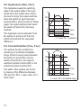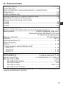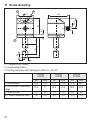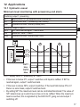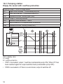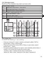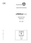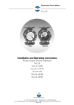
1
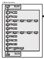
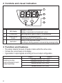
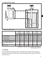
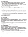
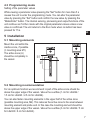
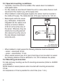
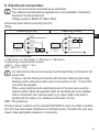
Operating instructions Electronic level sensor UK 701593/07 04/2006 LK7 / LK0 Contents 1 Menu structure�����������������������������������������������������������������������������������������������������3 2 Controls and visual indication������������������������������������������������������������������������������4 3 Function and features������������������������������������������������������������������������������������������4 3.1 Measuring range��������������������������������������������������������������������������������������������5 3.2 Offset�������������������������������������������������������������������������������������������������������������5 3.3 Applications���������������������������������������������������������������������������������������������������6 4 Operating modes�������������������������������������������������������������������������������������������������6 4.1 Run mode������������������������������������������������������������������������������������������������������6 4.2 Display mode�������������������������������������������������������������������������������������������������6 4.3 Programming mode���������������������������������������������������������������������������������������7 5 Installation�����������������������������������������������������������������������������������������������������������7 5.1 Mounting elements����������������������������������������������������������������������������������������7 5.2 Mounting recommendation����������������������������������������������������������������������������7 5.3 Special mounting conditions��������������������������������������������������������������������������8 5.4 Mounting accessories������������������������������������������������������������������������������������8 6 Electrical connection��������������������������������������������������������������������������������������������9 7 Programming�����������������������������������������������������������������������������������������������������10 8 Installation and set-up / operation��������������������������������������������������������������������� 11 8.1 Display during operation������������������������������������������������������������������������������ 11 8.2 Level at power on���������������������������������������������������������������������������������������� 11 8.3 Maintenance, cleaning, change of medium������������������������������������������������� 11 9 Technical information / Functioning / Parameters����������������������������������������������12 9.1 Adjustable parameters���������������������������������������������������������������������������������12 9.2 Hysteresis (Hno, Hnc):��������������������������������������������������������������������������������14 9.3 Fensterfunktion (Fno, Fnc): ������������������������������������������������������������������������14 10 Technical data��������������������������������������������������������������������������������������������������15 11 Scale drawing��������������������������������������������������������������������������������������������������16 12 Applications�����������������������������������������������������������������������������������������������������17 12.1 Hydraulic vessel����������������������������������������������������������������������������������������17 12.2 Pumping station�����������������������������������������������������������������������������������������18 12.3 Storage vessel�������������������������������������������������������������������������������������������19 2 1 Menu structure UK 3 2 Controls and visual indication 1 2 Mode/Enter Set 3 4 1 LED display 2 2 x LED red Mode / Enter button 3 4 Set button display of the level, display of parameters and parameter values switching status; lights if output I / II has switched selection of the parameters and acknowledgement of the parameter values setting of the parameter values (scrolling by holding pressed; incremental by pressing briefly) 3 Function and features • The sensor detects the level of media in tanks within the active zone. • It shows the current level on its display. • It generates 2 output signals according to the set output configuration. Switching function (can be selected for each output separately) 4 output 1 output 2 hysteresis function / N.O. (Hno) hysteresis function / N.C. (Hnc) window function / N.O. (Fno) window function / N.C. (Fnc) L UK A OFS min max A max min I 3.1 Measuring range A = measured / display value LK0022 LK7022 cm inch 26.4 10.4 19.5 7.7 5.3 2.0 1.5* 0.6* L = probe length A = active zone I = inactive zone min = lowest measured value max = highest measured 21.0* value OFS = offset 0...78.8 8.3* 0..30.7 LK0023 LK7023 cm inch 47.2 18.6 39.0 15.4 5.3 2.0 3.0* 1.2* LK0024 LK7024 cm inch 72.8 28.7 58.5 23.0 10.2 4.0 4.0* 1.6* 42.0* 62.0* 24.4* 0...186 0...73.2 16.6* 0...57.0 0...22.5 *With offset > 0 the OFS value is added to these values. factory setting: OFS = 0 3.2 Offset The area between the bottom of the vessel and the lower face of the measuring probe can be entered as offset value. Thus the display and the switch points refer to the real level. 5 3.3 Applications • The sensor continually monitors and adjusts to the medium. Thus it adapts itself to different media and compensates for changes in the medium. • For water and hydrous media with temperatures > 35°C install the unit into the climatic tube (order no. E43100, E43101, E43102). The sensor is not suitable for: • Very conductive and adhesive media (shampoo, toothpaste, glue, etc.). • Dry granulated materials with low density. • Media which are very inhomogeneous, separate from each other thus forming separation layers (e.g. oil layer on water which is several cm thick or a water layer at the bottom of a vessel filled with oil). -- Note: A thin oil film (a few mm) on water or water based media does not affect the function of the sensor. 4 Operating modes 4.1 Run mode Normal operating mode After power on and elapsing of the power-on delay time* (approx. 1 s) the unit is in the Run mode. It monitors and switches the transistor outputs according to the set parameters. The display indicates the current level, the red LEDs indicate the switching state of the outputs. is displayed. *During the power-on delay time 4.2 Display mode Indication of parameters and the set parameter values When the "Mode/Enter" button is pressed briefly, the unit passes to the Display mode which allows parameter values to be read. The internal sensing, processing and output functions of the unit continue as if in Run mode: • The parameter names are scrolled with each pressing of the "Mode/Enter" button. • When the "Set" button is pressed briefly, the corresponding parameter value is displayed for approx. 15 s. After another 15 s the unit returns to the Run mode. 6 4.3 Programming mode Setting of the parameter values While viewing a parameter value pressing the "Set" button for more than 5 s causes the unit to enter the programming mode. You can alter the parameter value by pressing the "Set" button and confirm the new value by pressing the "Mode/Enter" button. The internal sensing, processing and output functions of the unit continue as if in Run mode with the original parameter values unless a new value is confirmed. The unit returns to the Run mode when no button has been pressed for 15 s. A A M2 I M1 5.1 Mounting elements Mount the unit within the inactive zone, if possible (I; mounting area M1). The active zone (A) should be completely in the vessel. I 5 Installation 5.2 Mounting recommendation For an optimum function we recommend: A part of the active zone should be above the upper edge of the vessel / above the overflow (1 cm for LKx022 / 1.5 cm for LKx023 / 2.5 cm for LKx024). You can also fasten mounting elements in the upper half of the active zone (possible mounting area, M2). This reduces the active zone to the area between mounting element and probe end. In this case the mounting element should be above the upper edge of the vessel / above the overflow (3 cm for LKx022 / 5 cm for LKx023 / 8 cm for LKx024). 7 UK A 5.3 Special mounting conditions • If possible, mount the unit in the middle of the vessel when it is installed in small plastic tanks: • For dirty media we recommend: Fasten the unit in a zone where there is much movement of the medium (e.g. at the supply inlet). • When installed in metal rising pipes (bypass) the sensor must be mounted in the middle of the pipe. The inside diameter of the pipe must be min. 120 mm. • Metal objects within the vessel (e.g. metal pipes, components integrated into the vessel) must observe a minimum distance of 60 mm to the active zone of the sensor. Otherwise, they are detected as mounting element min. 60mm min. B 40mm (this reduces the active zone to the area between metal object and probe end). min. 10mm A = active zone B = metal component • When installed in metal vessels the following distances must be observed: -- sensor - vessel wall: 40 mm -- sensor - vessel bottom: 10 mm • When several sensors type LK or type LK and type LI are mounted in a vessel the following distance must be adhered to: min. 45 mm between the probes. 5.4 Mounting accessories For safe and easy mounting use the ifm mounting accessories (Order no. E43000 up to E43007). NOTE: Maximum vessel pressure when mounted with mounting accessories: 0.5 bar. An overpressure of 3 bar is possible for a short time (max. 1 min.). 8 6 Electrical connection The unit must only be connected by an electrician. The national and international regulations for the installation of electrical equipment must be observed. Voltage supply to EN50178, SELV, PELV. Disconnect power before connecting the unit. Wiring: p-switching (LK7xxx) 1 BN 2 WH n-switching (LK0xxx) 1 BN L+ 2 WH 4 BK 4: OUT1 2: OUT2 3 BU UK L+ 4 BK L 4: OUT1 2: OUT2 3 BU L Core colours of ifm sockets: 1 = BN (brown), 2 = WH (white), 3 = BU (blue), 4 = BK (black). Programming of complementary outputs: output 1: = Hno, output 2: = Hnc, SP1 = SP2 / rP1 = rP2. For safe function the sensor housing must be electrically connected to the vessel wall. To do so, use the housing connection with the blue cable lug (see scale drawing) and a cable piece with a wire cross-section of min. 1.5 mm² that is as short as possible. When using metal tanks the electrical ground of the tank serves as the machine earth. When using plastic tanks an electrode has to be installed that is connected to the machine earth (e.g. sheet metal in the tank in parallel with the probe; min. distance to the probe: 40 mm. EMC / CE guidelines The level sensor conforms to the standard EN 50081-2 and it is a class A product. The unit may cause radio interference in domestic areas. Therefore the user may have to take appropriate measures, if necessary. 9 7 Programming 1 2 Mode/Enter Set Mode/Enter Set Press the Mode/Enter button several times until the respective parameter is displayed. Press the Set button and keep it pressed. The current parameter value flashes for 5 s, then the value is increased* (incremental by pressing briefly or scrolling by holding pressed). Press the Mode/Enter button briefly (= acknowledgement). Mode/Enter Set 3 The parameter is displayed again, the set parameter value becomes effective. Finish programming: Change more parameters: Wait for 15 s or press the Mode/Enter 4 Start again with step 1. button until the current measured value is indicated again. *Decrease the value: Let the display of the parameter value move to the maximum setting value. Then the cycle starts again at the minimum setting value. Timeout: If no button is pressed for 15 s during the setting procedure, the unit returns to the run mode with unchanged values. The unit can be electronically locked to prevent unwanted adjustment of the set parameters: Press (in Run mode) both setting buttons for 10 s. As soon as the indication goes out the unit is locked or unlocked. Units are delivered from the factory in the unlocked state. is indicated briefly when you try to change With the unit in the locked state parameter values. 10 8 Installation and set-up / operation After mounting, wiring and setting check whether the unit operates correctly. 8.1 Display during operation switch on, initialisation XXX / XX.X --SC1, SC2 level indication; flashing: level close to the maximum measured value level below the active zone flashing = short circuit in switching output 1 or 2 UK 8.2 Level at power on At every power on the sensor initialises again. During this phase ensure that the vessel is not completely filled. Max. level at power on in cm from the lower edge of the sensor LKx22 20 LKx23 40.5 LKx24 59.5 If a mounting element (flange, etc.) is in the active zone, the level must have a minimum distance to the lower edge of the mounting element at power on: Minimum distance between the medium and mounting element in the active zone [cm] LKx22 3 LKx23 5 LKx24 8 The values are maintained if you follow the mounting recommendation (→ 5.2). 8.3 Maintenance, cleaning, change of medium Always carry out a reset in the following cases (disconnect the sensor briefly and then connect it again) so that the sensor initialises again. Observe the indications in the two tables above. • After all maintenance operations. • After cleaning operations (e.g. water jet cleaning of the sensor probe). • If the sensor has been removed from the vessel and then inserted again during operation. • If the active zone of the sensor has been touched with the hand or grounded objects (e.g. a screwdriver). • After a change of media if the dielectric constants differ much (e.g. oil/water). 11 9 Technical information / Functioning / Parameters 9.1 Adjustable parameters Switch-on point: Upper limit value at which the output changes its switching status, indicated in cm or inch. setting range cm inch in steps of LK0022 / LK7022 2.5 ... 20.5 1.0 ... 8.0 0.5 cm / 0.2 inch LK0023 / LK7023 4.0 ... 41.5 1.4 ... 16.2 0.5 cm / 0.2 inch LK0024 / LK7024 6.0 ... 61.0 2.5 ... 24.0 1.05 cm / 0.5 inch Values for OFS = 0; with OFS > 0 the OFS value is added to these values. Switch-off point: Lower limit value at which the output changes its switching status, indicated in cm or inch. setting range cm inch in steps of LK0022 / LK7022 2.0 ... 20.0 0.8 ... 7.8 0.5 cm / 0.2 inch LK0023 / LK7023 3.5 ... 41.0 1.2 ... 16.0 0.5 cm / 0.2 inch LK0024 / LK7024 5.0 ... 60.0 2.0 ... 23.5 1.05 cm / 0.5 inch Values for OFS = 0; with OFS > 0 the OFS value is added to these values. Dependence between rPx and SPx: 1. rPx is always lower than SPx. The unit only accepts values which are lower than SPx. 2. If the difference between rPx and SPx is small (approx. 3 x steps), increasing the switch-on point also increases the switch-off point (the difference SPx - rPx remains constant). 3. If the difference between rPx and SPx is great, rPx remains at the set value even if SPx is increased. 4. If SPx is set to the minimum value and then increased, rPx is also set to the minimum value and increased proportionally. Switching functions of the transistor outputs: 4 settings can be selected: -- Hno = hysteresis / normally open -- Hnc = hysteresis / normally closed -- Fno = window function / normally open -- Fnc = window function / normally closed 12 Offset (basic value for display and measured value): The area between the bottom of the vessel and lower face of the measuring probe can be entered as offset value. Thus the display and switch points refer to the real vessel level. setting range cm inch in steps of LK0022 / LK7022 0 ... 78 0 ... 30.6 0.5 cm / 0.2 inch LK0023 / LK7023 0 ... 57 0 ... 22.4 0.5 cm / 0.2 inch LK0024 / LK7024 0 ... 186 0 ... 74.5 1.05 cm / 0.5 inch Display unit: 2 settings can be selected: •EU = display in cm (Europe) •inc = display in inch Select the display unit before setting the switch points (SPx, rPx). This avoids rounding errors generated internally during the conversion of the units and enables exact setting of the values. Min-Max memory: •HI: Displays the highest measured level •LO: Displays the lowest measured level Erase the memory: - Press the "Mode/Enter" button until “HI” or “LO” is displayed. - Press the"Set" button and keep it pressed until “- - -” is displayed. - Then press the "Mode/Enter" button briefly. UK 13 9.2 Hysteresis (Hno, Hnc): The hysteresis keeps the switching state of the output stable if the level varies about the preset value. When the level is rising, the output switches when the switch-on point has been reached (SPx); when the level is falling again, the output switches back when the switch-off point (rPx) has been reached. The hysteresis can be adjusted: First the switch-on point is set, then the switch-off point with the requested difference. L = level; HY = hysteresis 9.3 Fensterfunktion (Fno, Fnc): The window function enables the monitoring of a defined acceptable range. When the level varies between the switch-on point (SPx) and the switch-off point (rPx), the output is switched (window function/NO) or not switched (window function/NC). The width of the window can be set by means of the difference between SPx and rPx. SPx = upper value, rPx = lower value. 14 L = level; FE = acceptable range 10 Technical data Operating voltage [V]............................................................................................ 12...30 DC Current rating [mA].......................................................................................................... 200 Short-circuit protection; reverse polarity protection / overload protection Voltage drop [V]............................................................................................................. < 2.5 Current consumption [mA].............................................................................................. < 80 Accuracy of switch point [% of value of measuring range]............................................... ± 5 Repeatability [% of value of measuring range.................................................................. ± 2 Maximum speed of the change of level [mm/s] - LKx022.......................................................................................................................... 100 UK - LKx023.......................................................................................................................... 200 - LKx024.......................................................................................................................... 300 Dielectric constant medium.............................................................................................. > 2 Maximum vessel pressure [bar] ((when mounted with mounting accessories)................ 0.5 Housing material......................................................... EPDM/X (Santoprene); FPM (Viton); Optalloy-plated brass; NBR (Buna N); PA; Pocan; PC (Macrolon); PP (polypropylene) Materials (wetted parts).......................................................................... PP (polypropylene) Protection................................................................................................................ IP 67, III Operating temperature [°C].......................................................................................... 0...60 Medium temperature - Oil [°C]........................................................................................................................ 0...65 - Coolant emulsions, water and hydrous media* - LKx022 [°C]............................................................................................................. 0...65 - LKx023 [°C]............................................................................................................. 0...60 - LKx024 [°C]............................................................................................................. 0...55 Storage temperature [°C]......................................................................................... -25...80 Shock resistance [g]............................................................ 12 (DIN EN 60068-2-29, 11 ms) Vibration resistance [g]............................................. 2.5 (DIN EN 60068-2-6, 10...2000 Hz) EMCEN 61000-4-2 ESD:........................................................................................ 4 / 8 kV EN 61000-4-3 HF radiated:............................................................................... 10 V/m EN 61000-4-4 Burst:............................................................................................ 2 kV EN 61000-4-4 Surge:................................................................................ 500 V /1 kV EN 61000-4-6 HF conducted:............................................................................... 10 V *For water and hydrous media with temperatures > 35°C install the unit into a climatic tube (order no. E43100, E43101, E43102). 15 11 Scale drawing 1 2 50 8,5 51 M12 x1 30,5 64 M A L I 3 16 1 = 7-segment LED display 2 = programming buttons 3 = housing connection with cable lug for cable 1.5 - 2.5 mm2 L = probe length A = active zone / measuring range I = inactive zone M = lowest measured value 16 LK0022 LK7022 cm inch 26.4 10.4 LK0023 LK7023 cm inch 47.2 18.6 LK0024 LK7024 cm inch 72.8 28.7 19.5 7.7 39.0 15.4 58.5 23.0 5.3 1.5 2.0 0.6 5.3 3.0 2.0 1.2 10.2 4.0 4.0 1.6 12 Applications 12.1 Hydraulic vessel Minimum level monitoring with prewarning and alarm Switching output 1: prewarning SP1 slightly above rP1 (to suppress wave movements) rP1 below preset level → prewarning, start refilling OU1 hysteresis function, normally closed (Hnc) Switching output 2: alarm SP2 min. value reached again → alarm reset rP2 below min. value → alarm OU2 hysteresis function, normally open (Hno) UK XX.X = display value, A = prewarning, B = alarm • If the level is below rP1, output 1 switches until liquid is refilled. If SP1 is reached again, output 1 switches back. • If the level is above SP2, output 2 switches. If the level falls below rP2 or if there is a wire break, output 2 switches back. • By setting SP1 the maximum level can be controlled/monitored: The value of SP1 determines up to which level (max) is to be refilled. When the maximum level is reached, this is signalled by the LED OUT1 going out and output 1 switching off. 17 12.2 Pumping station Empty the vessel with overflow protection Switching output 1: control to empty vessel SP1 upper value exceeded → submersible pump ON rP1 lower value reached → submersible pump OFF OU1 hysteresis function, normally open (Hno) Switching output 2: overflow protection SP2 maximum value exceeded → alarm rP2 slightly below SP2 (to suppress wave movements) OU2 hysteresis function, normally closed (Hnc) XX.X = display value A = empty B = overflow protection • If SP1 is exceeded, output 1 switches (submersible pump ON). When rP1 has been reached again the output switches back (submersible pump OFF). • If SP2 is exceeded or if there is a wire break, output 2 switches off. 18 12.3 Storage vessel Monitoring of the acceptable range (alarm) and level control Switching output 1: refilling SP1 upper preset value reached → finish refilling rP1 below lower preset value → start refilling OU1 hysteresis function, normally closed (Hnc) Switching output 2: safety function min - max SP2 max. value exceeded → alarm rP2 below min. value → alarm OU2 window function, normally open (Fno) UK XX.X = display value A = refill; B = min. monitoring; C = max. monitoring • If the level is below rP1, output 1 switches until liquid is refilled. If SP1 is reached again, output 1 switches back. • If the level is below rP2 or above SP2 or if there is a wire break, output 2 switches OFF (→ alarm). • The logical operation between the outputs 1 and 2 indicates whether there is overflow or the actual level is below the minimum level. -- Overflow: output 1 switched off and output 2 switched off. -- Below min. value: output 1 switched on and output 2 switched off. 19