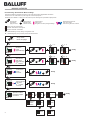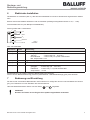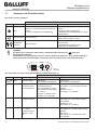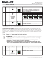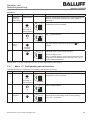
1
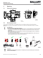
Montage- und Bedienungsanleitung Mounting and operating instructions BFS000F BFS 26K-GI-L04-S92 Farbsensor mit IO-Link Schnittstelle Colour sensor with interface IO-Link Inhalt / Content / Contenu Deutsch................................................................................................................... 5 English................................................................................................................... 26 Français...................................................................................................................X Copyright (Deutsch) Die Wiedergabe bzw. der Nachdruck dieses Dokuments, sowie die entsprechende Speicherung in Datenbanken und Abrufsystemen bzw. die Veröffentlichung, in jeglicher Form, auch auszugsweise, oder die Nachahmung der Abbildungen, Zeichnungen und Gestaltung ist nur auf Grundlage einer vorherigen, in schriftlicher Form vorliegenden Genehmigung seitens der Balluff GmbH, zulässig. Für Druckfehler und Irrtümer, die bei der Erstellung der Montageanleitung unterlaufen sind, ist jede Haftung ausgeschlossen. Liefermöglichkeiten und technische Änderungen vorbehalten. Erstveröffentlichung Dezember 2008. Copyright (English) No part of this document may be reproduced, published or stored in information retrieval systems or data bases in any manner whatsoever, nor may illustrations, drawings and the layout be copied without prior written permission from Balluff GmbH. We accept no responsibility for printing errors and mistakes which occurred in drafting this manual. Subject to delivery and technical alterations. First publication December 2008 Copyright (Français) Toute reproduction de ce document, ainsi que son enregistrement dans une base ou système de données ou sa publication, sous quelque forme que ce soit, même par extraits, ainsi que la contrefaçon des dessins et de la mise en page ne sont pas permises sans l’autorisation explicite et écrite de Balluff GmbH. Nous déclinons toute responsabilité concernent les fautes éventuelles d’impression et autres erreurs qui auraient pu intervenir lors du montage de cette brochure. Sous réserve de modifications techniques et de disponibilité pour livraison. Première publication Décembre 2008 Balluff GmbH Schurwaldstraße 9 D-73765 Neuhausen a.d.F. Kurzanleitung / Quick Guide / Manuel abrégé Hinweise zur Bedienung: Drücken der Tasten nur mit Finger! Keine spitzen Gegenstände verwenden! Instructions for use: Push buttons only with finger! Do not use sharp objects! Indications pour l’utilisation : N’ appuyer sur les boutons qu’avec les doigts ! Ne pas utiliser d’objets pointus ! SET Taste drücken Press button Appuyer bouton SET Taste loslassen Release button Relâcher bouton Farbe einlernen Teach colour Enregistrer la couleur par apprentissage Farbbereiche einscannen Scan colour range Scanner une gamme de couleurs LED EIN / LED ON / LED allumée LED blinkt / LED flashes / LED clignote LED AUS / LED OFF / LED éteinte W = Werkseinstellung / Factory setting / Configuration usine A = Abfallverzögerung / Drop-out delay / Retard au déclenchement SET 3s Einstellmodus Set-up mode Mode de réglage (1...4) C S +/F einlernen teach apprentissage SET 1 2 W 4 Tol.C SET Menü “C” (1...4) SET (1...4) C S +/F Menü “C+” C S +/F dazu lernen add colour apprentissage 2ème couleur SET einscannen scan scanner 1 2 W 4 Tol.C SET SET SET SET SET 1 W 3 4 Tol.I SET Ready (1...4) SET 1 W 3 4 Tol.I SET Ready Ready Menü “S” C S +/F Menü “S+” C S +/F Menü “F” dazu scannen add scan 2ème couleur scanner Sonderfunktionen Special functions Fonctions supplémentaires W SET SET aktiviert active active A SET ON SET 3 OFF Ready Pin 4: Q SET NO SET NC SET Ready Maßzeichnung / Dimensional drawing / Plan coté Abb. 1 / Illustr. 1 / Fig. 1 15300350 Anschluss / Wiring / Raccordement 1 BN 2 WH 3 BU 4 BK 5 GY Abb. 2 / Illustr. 2 / Fig. 2 15400487 4 +UB IN ET -UB Q/IO-Link IN TR Montage- und Bedienungsanleitung Inhaltsverzeichnis Inhaltsverzeichnis........................................................................................................................................................5 1 Symbolerklärung....................................................................................................................................................6 2 Sicherheitshinweise...............................................................................................................................................6 3 Bestimmungsgemäße Verwendung.......................................................................................................................7 4 Leistungsmerkmale...............................................................................................................................................7 5 Montage.................................................................................................................................................................8 5.1 Maßzeichnung..............................................................................................................................................8 5.2 Sensormontage.............................................................................................................................................8 6 Elektrische Installation...........................................................................................................................................9 7 Bedienung und Einstellung....................................................................................................................................9 7.1 Anzeigen und Einstellelemente...................................................................................................................10 7.2 Mögliche Einstellungen und Betriebsarten................................................................................................. 11 7.3 Einstellungen über das Bedienfeld vornehmen..........................................................................................12 7.3.1 Kurzanleitung (068-14274) siehe Ausklappseite................................................................................12 7.3.2 Einstellmodus (conf) aktivieren..........................................................................................................12 7.3.3 Menü „C”: Eine einzelne Farbe einlernen..........................................................................................12 7.3.4 Menü „C+”: Weitere Farben einlernen, hinzufügen, verknüpfen........................................................13 7.3.5 Menü „S”: Scannen eines einzelnen Farbbereiches..........................................................................15 7.3.6 Menü „S+”: Weitere Farbbereiche einscannen, hinzufügen, verknüpfen...........................................15 7.3.7 Menü „F“: Sonderfunktionen einstellen..............................................................................................16 8 Kommunikation über die IO-Link-Schnittstelle.....................................................................................................18 8.1 Grundlegende Eigenschaften der IO-Link-Schnittstelle..............................................................................18 8.2 Datenformate..............................................................................................................................................18 8.3 Prozessdaten..............................................................................................................................................19 8.4 Übersicht der Parameter (nach Datenkanälen sortiert)..............................................................................20 8.5 Integration in das Engineering System.......................................................................................................22 9 Pflege und Wartung.............................................................................................................................................23 9.1 Reinigung....................................................................................................................................................23 9.2 Transport, Verpackung, Lagerung..............................................................................................................23 9.3 Entsorgung..................................................................................................................................................23 10 Fehlersuche (Troubleshooting)............................................................................................................................23 11 Technische Daten................................................................................................................................................24 12 Bestellinformationen............................................................................................................................................25 12.1 Zubehör.......................................................................................................................................................25 BFS 26K mit IO-Link Nr. 862090 D Ausgabe 0907 5 Montage- und Bedienungsanleitung 1 Symbolerklärung Warnhinweise und sonstige Hinweise sind in dieser Anleitung durch Symbole gekennzeichnet. Sie werden durch Signalworte eingeleitet. Die verwendeten Symbole sind: WARNUNG ... weist auf eine möglicherweise gefährliche Situation hin, die zum Tod oder zu schweren Verletzungen führen kann, wenn sie nicht gemieden wird. VORSICHT ... weist auf eine möglicherweise gefährliche Situation hin, die zu Sachschäden führen kann, wenn sie nicht gemieden wird. HINWEIS Hebt nützliche Tipps und Empfehlungen sowie Informationen für einen effizienten Betrieb hervor. 2 Sicherheitshinweise Zur Vermeidung von Unfällen Personen- und Sachschäden, umsichtig handeln und unbedingt die folgenden Sicherheitshinweise beachten und einhalten: WARNUNG Das Produkt ist für das Sichern von Personen nicht zugelassen (kein Sicherheitsbauteil gemäß Maschinenrichtlinie). Alle in der Montage- und Bedienungsanweisung angegebenen Sicherheitshinweise und Handlungsanweisungen einhalten. Die geltenden örtlichen Unfallverhütungsvorschriften und allgemeinen Sicherheitsbestimmungen einhalten. Vor Beginn aller Arbeiten diese Montage- und Bedienungsanleitung sorgfältig lesen. Die Anleitung ist Produktbestandteil und muss in unmittelbarer Nähe des Sensors, für das Personal jederzeit zugänglich, aufbewahrt werden. Anschluss, Montage und Einstellung des Sensors darf nur durch Fachpersonal erfolgen. Eingriffe und Veränderungen am Gerät sind nicht zulässig! 6 BFS 26K mit IO-Link Nr. 862090 D Ausgabe 0907 Montage- und Bedienungsanleitung 3 Bestimmungsgemäße Verwendung Der BFS 26K ist ein Farbsensor zum Erkennen farblich unterschiedlicher Objekte im Tasterbetrieb (bei opaken Objekten) und Reflektorbetrieb (bei transparenten Objekten). WARNUNG Das Produkt ist für das Sichern von Personen nicht zugelassen (kein Sicherheitsbauteil gemäß Maschinenrichtlinie). 4 Leistungsmerkmale Die Farbsensoren der Baureihe BFS 26K sind ideal für die Online-Farberkennung in industriellen Abläufen und Prozessen. • Die Speicherung von Referenzfarben erfolgt einfach im Teach-in-Verfahren - wahlweise per Knopfdruck am Gerät oder über eine externe Eingabeleitung. • Die Farbselektivität (Farbe und Intensität) kann während dem Einlernen von Farben individuell an die spezifische Applikation angepasst werden. • Bei inhomogenen Farboberflächen kann ein Farbbereich / Farbspektrum eingescannt werden. • Über die „C+“ / „S+” Funktion ist es möglich Referenzfarben hinzuzufügen oder den Farbbereich in bis zu 4 Schritten zu erweitern ohne einen zu großen Farbbereich aufzuspannen. Dadurch wird eine hohe Farbselektivität auch über einen größeren Farbbereich mit bis zu 5 Farbmerkmalen erreicht. • Im laufenden Betrieb wird die Objektfarbe mit den eingelernten Sollwerten verglichen und das Ergebnis über den integrierten Schaltausgang angezeigt. Dieser BFS 26K ist mit einer IO-Link-Schnittstelle zum Übertragen der Farbwerte, sowie zum Einstellen von Sensorfunktionen ausgestattet. • Damit können beliebig viele Farben eingelernt und in Form von Farbvektoren (Sollwert inkl. Toleranzen) über die Schnittstelle in der Maschinensteuerung abgespeichert werden. • Vor Prozessbeginn wird die relevante Referenzfarbe wieder zurück zum Sensor übertragen. Im Betrieb vergleicht der Sensor die Istfarbe mit der Sollfarbe und signalisiert das Ergebnis am Schaltausgang. Die Zeit für das wiederholte Einlernen von Farben entfällt. • Über die Prozessdaten der IO-Link-Schnittstelle lassen sich die intern gespeicherten Farben / Farbbereiche (max. 5) getrennt auswerten Sonstige Leistungsmerkmale des Sensors im Überblick: • • • • • • Farberkennung auch im Durchlicht (auf Reflektor) möglich Hohe Farbselektivität, unempfindlich gegenüber Tastabstandsschwankungen Schaltart (N.O. / N.C.), einstellbar Betrieb wahlweise permanent oder getriggert (ausgetastet) möglich Anschlussstecker um 270° drehbar Wartungsfrei BFS 26K mit IO-Link Nr. 862090 D Ausgabe 0907 7 Montage- und Bedienungsanleitung 5 Montage 5.1 Maßzeichnung Abb. 4 15300065 Abb. 3 15300350 5.2 Sensormontage Sensor mit Befestigungsbohrungen an geeigneten Halter z.B. Typ BOS 26-HW-1 (nicht im Lieferumfang enthalten) schrauben. Sensor so positionieren, dass der Abstand vom Sensor zum Objekt möglichst konstant ist. HINWEIS Einsatzbedingungen beachten • Der Abstand zum Objekt muss innerhalb der Tastweite des Sensors liegen (siehe technische Daten). • Die Bewegungsrichtung des Objekts sollte quer zur Frontscheibe des Sensors verlaufen (Abb. 5+6). • Bei stark reflektierenden oder glänzenden Objektoberflächen den Sensor um ca. 10-30 ° zur Objektoberfläche neigen. (Abb. 7). • Bei Durchlichtbetrieb den Reflektor BOS R-1 gegenüber vom Farbsensor so montieren, dass der Lichtstrahl in der Mitte des Reflektors auftrifft. (Abb. 8). � � � Abb. 5 15500270 10-30° � Abb. 6 Abb. 7 15500697 Abb. 8 15500925 VORSICHT Bei starker Erschütterung (Schock / Schwingung) den Sensor konstruktiv vor Beschädigung schützen. 8 BFS 26K mit IO-Link Nr. 862090 D Ausgabe 0907 Montage- und Bedienungsanleitung 6 Elektrische Installation Gerätestecker so verdrehen (Abb. 3), dass das Anschlusskabel frei und ohne abzuknicken angeschlossen werden kann. Buchse des Anschlusskabels aufstecken und verschrauben (zulässige Anzugsdrehmomente ca. 0,5 ...1 Nm). Anschlusskabel sichern (zum Beispiel mit Kabelbinder). Sensor gemäss Abb. 9 anschließen. 1 BN 2 WH 3 BU 4 BK 5 GY +UB IN ET -UB Q/IO-Link IN TR Abb. 9 15400487 Abb. 9 Anschlussbild Anschluss Farbe Verwendung 1 (BN) Braun + UB = Versorgungsspannung 2 (WH) Weiß IN ET = Eingang für Extern Teach Teach-in wenn High (18 ... 30 V DC) Normalbetrieb wenn Low (< 3 V) oder unbeschaltet Min. Ansprechzeit 2 ms 3 (BU) Blau - UB = Versorgungsspannung 4 (BK) Schwarz Q / IO-Link = Schaltausgang / IO-Link-Anschluss 5 (GY) Grau IN TR = Eingang für Triggerung getriggert wenn High (18 ... 30 V DC) freilaufend wenn Low (< 3 V) oder unbeschaltet Ansprechzeit < 10 ms Betriebsspannung einschalten (zulässige Betriebsspannung beachten). Sensor ist nach Bereitschaftsverzug (≤ 300 ms) betriebsbereit. LED Betriebsanzeige (grün) muss leuchten. 7 Bedienung und Einstellung Der Sensor hat verschiedene Betriebsarten und Funktionen. Er verfügt über eine IO-Link-Schnittstelle zur Übertragung von Farbwerten und zum Einstellen der Sensorfunktionen. Über das Bedienfeld wird der Sensor mit den Tasten SET und eingestellt. VORSICHT Drücken der Tasten nur mit Finger! Keine spitzen Gegenstände verwenden! BFS 26K mit IO-Link Nr. 862090 D Ausgabe 0907 9 Montage- und Bedienungsanleitung 7.1 Anzeigen und Einstellelemente Die Tasten und ihre Funktion: Generelle Bedienfunktionen Tasten SET SET ESC Bezeichnung Im Betriebsmodus Im Einstellmodus SET Taste > 3 s drücken aktiviert den Einstellmodus LED „C” blinkt gelb zur Bestätigung Kurzes Drücken und wieder Loslassen bewirkt: Sprung in das nächste Menü Übernahme und Bestätigung von eingestellten Werten Weiterschalten Keine Funktion Einstellungen ändern und Sprung zum jeweils nächsten Menü / Punkt Bedienfeld komplett Beide Tasten gleichzeitig drücken bewirkt ESC (Escape) Einstellmodus verlassen ohne Änderungen zu übernehmen Keine Funktion HINWEIS Ein Zeitschloss verhindert, dass kurzes, unbeabsichtigtes Drücken der SET -Taste den Einstellmodus aktiviert. Nach Öffnen des Einstellmodus wird ein weiteres Zeitfenster (Dauer ca. 20 s) geöffnet. Erfolgt in dieser Zeit keine weitere Eingabe, schaltet der Sensor wieder zurück in den Betriebsmodus. C S +/F Tol.C Tol.I Conf. SET ESC Abb. 10 15500349 Die LEDs (Abb. 10) zeigen die gewählten Menüs und Einstellungen an. Anzeigefunktion LED 10 Farbe Verwendung Im Betriebsmodus Im Einstellmodus Grün Betriebsanzeige LEUCHTET, wenn Sensor betriebsbereit. LEUCHTET, wenn Sensor betriebsbereit. C Gelb C = Colour Farbe teachen Schaltzustand LEUCHTET (in Schaltart N.O. = Werkseinstellung), wenn Objektfarbe = eingelernte Farbe (Schaltausgang „Q” = aktiv). Funktion = invertiert, wenn Schaltart N.C. eingestellt BLINKT, wenn Menü „C” (eine Farbe einlernen) gewählt, BLINKT mit „+/F”, wenn Menü „C”+ gewählt S Gelb S = Scan Farbe scannen Keine Funktion BLINKT, wenn Menü „S” (eine Farbe einscannen) gewählt, BLINKT mit „+/F”, wenn Menü „S+” gewählt. +/F Gelb C+ = Teach+ S+ = Scan+ weitere Farben einlernen / scannen Keine Funktion BLINKT mit „C”, wenn Menü „C+” (Farben dazu lernen) gewählt oder mit „S”, wenn Menü „S+” (Farben dazu scannen) gewählt BFS 26K mit IO-Link Nr. 862090 D Ausgabe 0907 Montage- und Bedienungsanleitung Anzeigefunktion LED Farbe Verwendung Grün blinkend F = Functions Keine Funktion (Sonderfunktionen) BLINKT, wenn Menü „F” (Sonderfunktionen) gewählt Tol. C Grün Tol. C (Tolerance Col.) Keine Funktion Farbtoleranz einstellen (in 4 Stufen einstellbar) Tol. I Rot Tol. I (Tolerance Int.) Keine Funktion Intensität (Graustufen) einstellen (in 4 Stufen einstellbar) Tol. C Tol. I Rot blinkend Spezifische Sonderfunktionen Keine Funktion Sonderfunktionen werden über spezifische LED Kombination angezeigt +/F 7.2 Im Betriebsmodus Im Einstellmodus Mögliche Einstellungen und Betriebsarten Beim BFS 26K können verschiedene Einstellungen vorgenommen werden. Sie sind in 5 Hauptmenü-Bereiche unterteilt. Mögliche Funktionen, Einstellungen und Betriebsarten sind: Werkseinstellung Hauptmenü „C” (Colour) • Eine (einzelne) Farbe einlernen (teachen) Die Toleranz für Farbton und Intensität ist separat einstellbar. Neutral Weiß (Kodak 90%) Hauptmenü „C+” Colour +) • Eine weitere Farbe einlernen (teachen) und mit bis zu 4 bereits eingelernten Farben ODER-verknüpfen Die Toleranz für Farbton und Intensität ist separat einstellbar. Neutral Weiß (Kodak 90%) für alle Kanäle Hauptmenü „S” (Scan) • Ein Farbspektrum (einen Farbbereich) einscannen Neutral Weiß (Kodak 90%) Hauptmenü „S+” (Scan +) • Weitere Farbbereiche einscannen, hinzufügen und mit bis zu 4 bereits gescannten Farbbereichen ODER-verknüpfen Neutral Weiß (Kodak 90%) für alle Kanäle Hauptmenü „F” (Functions) • Sensor in Werksauslieferungszustand zurücksetzen - • Abfallverzögerung einstellen Abfallverzögerung deaktiviert • Schaltart (N.O. / N.C.) einstellen Schaltart N.O. (Schließer) Zusätzlich über die elektrische Schnittstelle: • Über die externe Eingabeleitung „IN ET“ ist das Einlernen einer Referenzfarbe möglich • Über die IO-Link-Schnittstelle können alle Sensorfunktionen eingestellt und ausgelesen werden • Über die IO-Link-Schnittstelle können die einzelnen Farben / Farbbereiche einzeln ausgewertet werden BFS 26K mit IO-Link Nr. 862090 D Ausgabe 0907 11 Montage- und Bedienungsanleitung 7.3 Einstellungen über das Bedienfeld vornehmen 7.3.1 Kurzanleitung (068-14274) siehe Ausklappseite 7.3.2 Einstellmodus (conf) aktivieren HINWEIS = LED EIN / Aktivität = LED blinkt / Es folgt Bild SET >3s Bemerkung LED blinkt, wenn Einstellmodus aktiviert ist. C S +/F Nach Aktivieren des Einstellmodus wird ein weiteres Zeitfenster von ca. 20 s geöffnet. Erfolgt in dieser Zeit keine weitere Eingabe, schaltet der Sensor wieder zurück in den Betriebsmodus. drücken, bis LED „C” (gelb) blinkt 7.3.3 = LED AUS Menü „C”: Eine einzelne Farbe einlernen HINWEIS • Wird eine Farbe eingelernt, werden alle vorher eingelernten sowie eingescannten Farben / Farbbereiche gelöscht. • Die Farb- und Intensitätstoleranz ist während des Programmiervorganges individuell einstellbar. • Nach dem Einlernvorgang leuchtet die gelbe LED „C”, wenn der Schaltausgang „Q” aktiv ist / eine Farbe erkannt worden ist (wenn Schaltart = N.O. = Werkseinstellung eingestellt). Ablauf: Schritt Menüpunkt Aktivität 1 Betriebsmo- Objekt dus (kein positionieren Menüpunkt) 2 SET >3s Es folgt Bild Bemerkung Betriebsparameter wie Tastweite, Bewegungsrichtung, Neigungswinkel, etc. (siehe Kapitel 5 „Montage”) beachten. C S +/F LED „C” (gelb) blinkt, wenn Zeitschloss geöffnet und Einstellmodus aktiviert ist. drücken, bis LED „C” (gelb) blinkt 3 4 Farbe einlernen drücken SET wieder loslassen 12 Taste kurz drücken (mit dem Loslassen der Taste wird die Farbe eingelernt). SET C S +/F Farbwert wird im Sensor gespeichert. Sensor ist bereit für die Einstellung der Farbtoleranz. LED „C” (gelb) leuchtet, wenn Farbe erkannt wird,* LEDs „Tol. C” (grün) leuchten. BFS 26K mit IO-Link Nr. 862090 D Ausgabe 0907 Montage- und Bedienungsanleitung Schritt 5 Menüpunkt Aktivität Es folgt Bild mehrfach Bemerkung Farbtoleranz (Farbselektivität) auswählen 1 2 3 drücken, bis gewünschte Toleranz gewählt ist C S +/F C S +/F 4 C S +/F C S +/F 1 = kleinste Toleranz, 4 = größte Toleranz 3 = Werkseinstellung 6 mit SET C S +/F bestätigen 7 mehrfach Farbtoleranz ist übernommen. Sensor ist bereit für die Einstellung der Intensitätstoleranz LED „C” (gelb) leuchtet, wenn Farbe erkannt wird,* LEDs „Tol.I” (rot) leuchten. Intensitätstoleranz (Grauselektivität) auswählen 1 2 3 3 drücken, bis gewünschte Toleranz gewählt ist C S +/F C S +/F C S +/F C S +/F 1 = kleinste Toleranz, 4 = größte Toleranz 2 = Werkseinstellung 8 mit SET C S +/F bestätigen Sensor ist einsatzbereit. LED „C” (gelb) leuchtet, wenn Farbe erkannt / Schaltausgang „Q” aktiv ist*. * wenn Schaltart = N.O. = Werkseinstellung eingestellt. Farbe einlernen über Eingang IN ET: Der Teach-in-Vorgang kann auch über die Eingabeleitung IN ET ausgelöst werden. Hierzu muss die Eingabeleitung > 3s auf High-Pegel gesetzt werden (Zeitschloss). Die Farbe wird mit dem Wechsel der Flanke (von High auf Low) eingelernt. Nach dem Einlernen wird die Farbe mit den Toleranzeinstellungen, die zuletzt manuell verwendet worden sind, gespeichert. Wurde noch keine Farbe manuell (über das Bedienfeld) eingelernt, werden die werksseitig eingestellten Werte (Farbwerttoleranz Stufe 3 / Intensitätstoleranz Stufe 2) übernommen. 7.3.4 Menü „C+”: Weitere Farben einlernen, hinzufügen, verknüpfen HINWEIS • Über die „C+” („Teach +”) Funktion ist es möglich, 1 bis 4 weitere Referenzfarben einzulernen. Sie werden automatisch miteinander verknüpft. Die vorher eingelernten und eingescannten Farben / Farbbereiche bleiben erhalten. • Die Farb- und Intensitätstoleranz ist während des Programmiervorganges individuell einstellbar. • Bei mehr als 5 Farben werden die ältesten überschrieben (FIFO). • Nach dem Einlernvorgang leuchtet die gelbe LED „C”, wenn der Schaltausgang „Q” aktiv ist / eine Farbe erkannt worden ist (wenn Schaltart = N.O. = Werkseinstellung eingestellt). BFS 26K mit IO-Link Nr. 862090 D Ausgabe 0907 13 Montage- und Bedienungsanleitung Ablauf: Schritt Menüpunkt Aktivität 1 Betriebsmo- Objekt dus (kein positionieren Menüpunkt) 2 SET >3s Es folgt Bild Bemerkung Betriebsparameter wie Tastweite, Bewegungsrichtung, Neigungswinkel, etc. (siehe Kapitel 5 „Montage”) beachten. C S +/F LED „C” (gelb) blinkt, wenn Zeitschloss geöffnet und Einstellmodus aktiviert ist. C S +/F Menü „weitere Farben einlernen” ist gewählt LED „C“ und „+” (gelb) blinken. drücken bis LED „C” (gelb) blinkt 3 drücken 4 5 Farbe einlernen SET wieder loslassen 6 Taste kurz drücken (mit dem Loslassen der Taste wird die Farbe eingelernt). SET C S +/F mehrfach Farbwert wird im Sensor gespeichert. Sensor ist bereit für die Einstellung der Farbtoleranz. LED „C” (gelb) leuchtet, wenn Farbe erkannt wird,* LEDs „Tol. C” (grün) leuchten. Farbtoleranz (Farbselektivität) auswählen 1 2 3 drücken, bis gewünschte Toleranz gewählt ist C S +/F C S +/F 4 C S +/F C S +/F 1 = kleinste Toleranz, 4 = größte Toleranz 3 = Werkseinstellung 7 mit SET C S +/F bestätigen 8 mehrfach Farbtoleranz ist übernommen. Sensor ist bereit für die Einstellung der Intensitätstoleranz. LED „C” (gelb) leuchtet, wenn Farbe erkannt wird,* LEDs „Tol.I” (rot) leuchten Intensitätstoleranz (Grauselektivität) auswählen 1 2 3 4 drücken, bis gewünschte Toleranz gewählt ist C S +/F C S +/F C S +/F C S +/F 1 = kleinste Toleranz, 4 = größte Toleranz 2 = Werkseinstellung 9 mit SET bestätigen 14 C S +/F Sensor ist einsatzbereit. LED „C” (gelb) leuchtet, wenn Farbe erkannt / Schaltausgang „Q” aktiv ist.* BFS 26K mit IO-Link Nr. 862090 D Ausgabe 0907 Montage- und Bedienungsanleitung * wenn Schaltart = N.O. = Werkseinstellung eingestellt. Zum Einlernen (Hinzufügen) weiterer Farben den Einstellablauf (Schritte 1-8) wiederholen. 7.3.5 Menü „S”: Scannen eines einzelnen Farbbereiches HINWEIS • Funktion für das Einscannen einer inhomogenen Farboberfläche. • Wird eine Farbe eingescannt, werden alle vorher eingelernten und eingescannten Farben / Farbbereiche gelöscht. • Nach dem Einscannvorgang leuchtet die gelbe LED „C”, wenn der Schaltausgang aktiv ist / eine Farbe erkannt wurde (wenn Schaltart = N.O. = Werkseinstellung eingestellt). Ablauf: Schritt Menüpunkt Aktivität 1 Betriebsmo- Objekt dus (kein positionieren Menüpunkt) 2 Es folgt Bild SET >3s Bemerkung Betriebsparameter wie Tastweite, Bewegungsrichtung, Neigungswinkel, etc. (siehe Kapitel 5 „Montage”) beachten. C S +/F LED „C” (gelb) blinkt, wenn Zeitschloss geöffnet und Einstellmodus aktiviert ist. C S +/F Menü „Farbbereich einscannen” ist gewählt LED „S” (gelb) blinkt C S +/F Solange SET gedrückt ist, wird der Farbbereich eingescannt. drücken bis LED „C” (gelb) blinkt 3 2x drücken 4 5 Farbbereich einscannen SET drücken und gedrückt halten SET loslassen 7.3.6 C S +/F Farbbereich wird gespeichert. Sensor ist einsatzbereit. LED „C” (gelb) leuchtet, wenn Farbe erkannt / Schaltausgang „Q” aktiv ist (wenn Schaltart = N.O. = Werkseinstellung eingestellt). Menü „S+”: Weitere Farbbereiche einscannen, hinzufügen, verknüpfen HINWEIS • Über die „S+” („Scan +”) Funktion ist es möglich 1 bis 4 weitere Farbbereiche einzuscannen und den Farbbereich in bis zu 4 Schritten zu erweitern • Wird mit „S+” („Scan+”) ein Farbbereich eingescannt, bleiben die vorher eingelernten und eingescannten Farben erhalten. • Bei mehr als 5 Farbbereichen werden die ältesten überschrieben (FIFO). • Nach dem Einscannvorgang leuchtet die gelbe LED „C”, wenn der Schaltausgang aktiv ist / eine Farbe erkannt worden ist (wenn Schaltart = N.O. = Werkseinstellung eingestellt). BFS 26K mit IO-Link Nr. 862090 D Ausgabe 0907 15 Montage- und Bedienungsanleitung Ablauf: Schritt Menüpunkt Aktivität 1 Betriebsmo- Objekt dus (kein positionieren Menüpunkt) 2 SET >3s Es folgt Bild Bemerkung Betriebsparameter wie Tastweite, Bewegungsrichtung, Neigungswinkel, etc. (siehe Kapitel 5 „Montage”) beachten. C S +/F LED „C” (gelb) blinkt, wenn Zeitschloss geöffnet und Einstellmodus aktiviert ist. C S +/F Menü „weitere Farbbereiche einscannen” ist gewählt. LED „S” und „+” (gelb) blinken. drücken bis LED „C” (gelb) blinkt 3 3x drücken 4 Weitere Farbbereiche einscannen 5 SET Solange SET gedrückt ist, wird der zusätzliche Farbbereich eingescannt. drücken und gedrückt halten SET loslassen C S +/F Zusätzlicher Farbbereich wird gespeichert. Sensor ist einsatzbereit. LED „C” (gelb) leuchtet, wenn Farbe erkannt / Schaltausgang „Q” aktiv ist (wenn Schaltart = N.O. = Werkseinstellung eingestellt).. Zum Einlernen (hinzufügen) weiterer Farbbereiche den Einstellablauf (Schritte 1-5) wiederholen. 7.3.7 Menü „F“: Sonderfunktionen einstellen In diesem Menü werden die einzelnen Sonderfunktionen eingestellt oder aktiviert / deaktiviert. Schritt Menüpunkt Aktivität Es folgt Bild SET C S +/F LED „C” (gelb) blinkt, wenn Zeitschloss geöffnet und Einstellmodus aktiviert ist. C S +/F Menü „Sonderfunktionen” ist gewählt. LED „F“ (grün) blinkt. 1 >3s Bemerkung drücken bis LED „C“ (gelb) blinkt 2 4x drücken 3 16 Sonderfunktionen SET drücken C S +/F Menü „Sonderfunktionen” ist aktiviert. Sensor springt zur ersten Einstellung (Rücksetzen in Werkseinstellung). LEDs „Tol. I” (rot) blinken. BFS 26K mit IO-Link Nr. 862090 D Ausgabe 0907 Montage- und Bedienungsanleitung Schritt Menüpunkt Aktivität Es folgt Bild In Werkseinstellung zurücksetzen C S +/F Bemerkung LEDs „Tol. I” (rot) blinken. C S +/F Mit SET Sensor auf Werkseinstellung zurücksetzen. 4 Wurde SET gedrückt, blinkt zur Bestätigung die LED „+/F” (grün) im Wechsel mit den LEDs „Tol. I” (rot). Weiter zur nächsten Funktion (Abfallverzögerung) drücken Abfallverzögerung C S +/F Abfallverzögerung inaktiv: C S +/F Mit SET aktivieren. 5 Mit SET deaktivieren. Weiter zur nächsten Funktion (Schaltart Schaltausgang „Q” einstellen) drücken Schaltart Q einstellen Abfallverzögerung aktiv: C S +/F „Q” (PIN 4) ist als Schließer eingestellt. Mit SET umschalten auf Öffner. 6 C S +/F „Q” (PIN 4) ist als Öffner eingestellt. Mit SET umschalten auf Schließer. Weiter zu „Menüausgang” drücken Menüausgang 7 C S +/F SET drücken BFS 26K mit IO-Link Nr. 862090 D Ausgabe 0907 Die Einstellungen werden gespeichert, der Einstellmodus wird verlassen. 17 Montage- und Bedienungsanleitung 8 Kommunikation über die IO-Link-Schnittstelle IO-Link ist eine intelligente Punkt-zu-Punkt-Verbindung, signal- und anschlusskompatibel zur binären StandardSchnittstelle. Der BFS 26K ist mit dieser Schnittstelle ausgestattet. Es können Farbwerte übertragen oder Sensorfunktionen eingestellt werden. Damit ergeben sich folgende Nutzungsmöglichkeiten: • Sensorintern können bis zu 5 Referenzfarben eingelernt und verwaltet werden. Die gemessen Farbwerte werden mit den gespeicherten Referenzfarbwerten verglichen. Liegen diese innerhalb der definierten Toleranzbereiche, wird die Information „Farbe erkannt” mit den Prozessdaten ausgegeben. • Referenzfarben können eingelernt und in Form von Farbvektoren (Sollwert inkl. Toleranzen) über die Schnittstelle in der Maschinensteuerung abgespeichert werden. Vor Prozessbeginn wird die relevante Referenzfarbe zurück zum Sensor übertragen. Im SIO-Mode vergleicht der Sensor dann die Istfarbe mit der Referenzfarbe und signalisiert das Ergebnis am Signalausgang. • Es ist möglich die aktuell gemessenen Farbwerte über die Schnittstelle auszugeben. In diesem Fall muss der Vergleich der Istfarbe mit der Referenzfarbe über die Steuerung erfolgen. 8.1 Grundlegende Eigenschaften der IO-Link-Schnittstelle Nach Einschalten der Betriebsspannung ist der Sensor im I/O-Modus (SIO-Mode). Per „Wake up” wird er in den Kommunikationsmodus (COM-Mode) gesetzt. Es können Prozessdaten zyklisch übertragen und Parameter-/Servicedaten azyklisch empfangen und gesendet werden. Die physikalischen Eigenschaften der IO-Link-Schnittstelle des Sensors sind: Physik: SIO-Modus: Min. Zykluszeit: Frame-Typ: Prozessdatenbreite: 8.2 COM 2 (38,4 kBaud) ja 2,6 ms 2.1 1 Byte Datenformate Die Datenübertragung zum IO-Link Master folgt dem Type 2.1 Frame der IO-link-Spezifikation. Die übertragenen Werte können in folgenden Formaten auftreten: IntegerT (8): Zahlenwerte mit 8 Bit Wortbreite StringT Strings werden Byteweise gemäß ASCII-Code übertragen. 18 BFS 26K mit IO-Link Nr. 862090 D Ausgabe 0907 Montage- und Bedienungsanleitung 8.3 Prozessdaten Funktion Zugriffsart Adresse Datenformat Belegung der Bits Wertebereich Prozessdaten R 00h IntegerT (8) Bit 0 copy of output state SIO-mode Bit 1 1 = colour 1 detected Bit 2 1 = colour 2 detected Bit 3 1 = colour 3 detected Bit 4 1 = colour 4 detected Bit 5 1 = colour 5 detected Bit 6,7 not used (= 00) HINWEIS Wird nur eine Referenzfarbe eingelernt gehen alle benutzten Bits (Bit 0 ... Bit 5) auf High (1), wenn die im laufenden Betrieb gemessene Farbe der eingelernten Referenzfarbe entspricht. Erst bei der Addition von Farben (C+) werden die Zustände einzeln dargestellt. BFS 26K mit IO-Link Nr. 862090 D Ausgabe 0907 19 Montage- und Bedienungsanleitung 8.4 Übersicht der Parameter (nach Datenkanälen sortiert) Parameterdaten Adresse Objektname 00h Zugriffsart * Master Command R/W Wert Wertebereich Bemerkung 00h Write: 5Ah - initate fallback 97h - goto start-up state 99h - goto operate state, PD out invalid Read: no requirements Command interface for control of communication state machine A0h-FFh reserved for vendor specific extension 01h Master cycle time R/W 00h 0 - 537.6 ms bit 6, 7 = time base bit 0-5 = multiplier 0x00 02h Min. cycle time R 1Ah 0 - 537.6 ms bit 6-7 = time base bit 0-5 = multiplier 2,6 ms 03h Frame Capability R 01h bit 0 = SPDU support bit 1 = frame type 1 support (parameter transfer only) bit 7 = PHY2: 0 / PHY1: 1 SPDU supported 04h IO-Link Revision ID R 10h lower nibble: minor revision upper nibble:major revision Actual revision code: Example: 1.0 05h Process data in R 46h Start-up Parameter bit 0-4 bit 5 bit 6 bit 7 = length = 0 (reserved) = SIO mode support = length in bit: 0, byte: 1 (only ≥ 16 bit) SIO mode supported; process data = 6 bits: Bit 0 = output at SIO mode Bit 1..Bit 5 = colour 1..5 detected 06h Process data out R 00h bit 0-4 bit 5 bit 6 bit 7 = length 0x00 (no process data out) = 0 (reserved) = SIO mode support = length in bit: 0, byte: 1 (only ≥ 16 bit) 07h Vendor ID 1 R 03h 08h Vendor ID 2 R 78h unique vendor ID defined by IO-Link Consortium 09h Device ID 1 R 04h 0Ah Device ID 2 R 01h 0Bh Device ID 3 R 01h 0Ch Function ID 1 R/W 00h 0Dh Function ID 2 R/W 00h 20 vendor specific device ID defined by vendor specific code for device function 0000h - not used, no validation 0001h - 7FFFh - reserved 8000h - FFFFh - vendor specific vendor specific not supported BFS 26K mit IO-Link Nr. 862090 D Ausgabe 0907 Montage- und Bedienungsanleitung Service-PDU-Daten Funktion Zugriffs- Index art * Wertebereich Direct Parameter Page R/W 0 00h 16 entries Direct Parameter Page R/W 1 01h 16 entries System Command Index W 2 02h 1 Byte Funktion Zugriffs- Index art * Bemerkung dez. hex. Datenformat Belegung Wertebereich der Bits Command Code Definition Vendor specific: A0h: factory preset A1h: teach A2h: scan Afh: save to flash Bemerkung dez. hex. Identifikationsdaten Vendor Name R 16 10 StringT Balluff Vendor Text R 17 11 StringT www.balluff.com Product Name R 18 12 StringT BFS 26K-GI-L04-S92 Product-ID R 19 13 StringT BFS000F Hardware Revision R 22 16 StringT 2 byte Firmware Revision R 23 17 StringT 2 byte 40 2x IntegerT (8) Byte 1 Device control Byte 2 BFS 26K mit IO-Link Nr. 862090 D Ausgabe 0907 Bit 0 0 = N.O. (Schließer) 1 = N.C. (Öffner) Bit 2 0 = no output delay (keine Abfallverzögerung) 1 = output delay (Abfallverzögerung) Bit 6 0 = no button lock (keine Tastenverriegelung) 1 = button lock (Tastenverriegelung) Bit [1:0] 00 = Colour tolerance step 1 01 = Colour tolerance step 2 10 = Colour tolerance step 3 11 = Colour tolerance step 4 Bit [3:2] 00 = Ievel tolerance step 1 01 = level tolerance step 2 10 = level tolerance step 3 11 = level tolerance step 4 2 byte 21 Montage- und Bedienungsanleitung Funktion Zugriffs- Index art * Datenformat Belegung Wertebe- Bemerkung der Bits reich dez. hex. Im Sensor gespeicherte Referenzfarbwerte (inkl. Toleranzen) Colour vector 1 R/W 41 3x IntegerT (16) 6 Byte Colour values channel 1 Farbwerte Kanal 1 Colour vector 2 R/W 42 3x IntegerT (16) 6 Byte Colour values channel 2 Farbwerte Kanal 2 Colour vector 3 R/W 43 3x IntegerT (16) 6 Byte Colour values channel 3 Farbwerte Kanal 3 Colour vector 4 R/W 44 3x IntegerT (16) 6 Byte Colour values channel 4 Farbwerte Kanal 4 Colour vector 5 R/W 45 3x IntegerT (16) 6 Byte Colour values channel 5 Farbwerte Kanal 5 16 Byte Byte 0: Process data (Prozessdaten) Byte 1: not used (nicht belegt) Byte 2+3: red Byte 4+5: green Byte 6+7: level Remaining bytes (restliche Byte): not used (nicht belegt) Gemessene Farbwerte R 46 * R = Read W = Write HINWEIS Wird auf einen nicht zur Verfügung stehenden Index geschrieben oder gelesen, antwortet der Sensor mit der Fehlermeldung „Subindex not available”. 8.5 Integration in das Engineering System Die Parametrierung des BFS 26K erfolgt im Engineering System mittels IODD-Datei (IO-Link Device Description). Die zum Farbsensor BFS 26K passende IODD-Datei ist im Internet als Download verfügbar unter: www.balluff.com 22 BFS 26K mit IO-Link Nr. 862090 D Ausgabe 0907 Montage- und Bedienungsanleitung 9 Pflege und Wartung 9.1 Reinigung Bei Verschmutzung die Frontscheibe des Sensors mit einem weichen Tuch und ggf. etwas Kunststoffreiniger reinigen. VORSICHT Niemals aggressive Reinigungsmittel verwenden. 9.2 Transport, Verpackung, Lagerung Die Lieferung bei Erhalt unverzüglich auf Vollständigkeit und Transportschäden prüfen. Bei Transportschäden den Transporteur benachrichtigen. Bei Rücksendungen den Sensor immer in einer ausreichend stabilen Verpackung verschicken. HINWEIS Jeden Mangel reklamieren, sobald er erkannt ist. Ansprüche können nur innerhalb der geltenden Fristen geltend gemacht werden. 9.3 Entsorgung Elektronikkomponenten unterliegen der Sondermüllbehandlung und dürfen nur durch Fachbetriebe entsorgt werden. 10 Fehlersuche (Troubleshooting) Fehlerbeschreibung Die Programmierung über das Tastenfeld ist nicht möglich. Mögliche Ursache Die Taste SET wurde zu kurz gedrückt (< 3 s) und aufgrund des Zeitschlosses wurde der Einstellmodus nicht aktiviert. Über die IO-Link-Schnittstelle wurde per Befehl die Tastenverriegelung aktiviert. Behebung SET >3s drücken Tastenverriegelung wieder aufheben. Bei davon abweichenden Störungen wenden Sie sich bitte an Ihren Balluff-Ansprechpartner in den für Sie zuständigen Vertretungen und Geschäftsstellen. BFS 26K mit IO-Link Nr. 862090 D Ausgabe 0907 23 Montage- und Bedienungsanleitung 11 Technische Daten Optische Daten (typ.) Tastweite (ab Referenzpunkt) 12 ... 32 mm Tastweitentoleranz *1 ± 6 mm (bei Tol C 3 und Tol I 2) Lichtfleckgröße Ø 4 mm bei Tastweite 22 mm Betriebsreichweite mit Reflektor BOS R-1 applikationsspezifisch Lichtart Weißlicht (gepulst) Fremdlichtgrenze EN 60947-5-2 Farb-/ Intensitätstoleranz einstellbar (je 4 Stufen) Elektrische Daten (typ.) Betriebsspannung UB 18 ... 30 V DC Restwelligkeit innerhalb UB 10 % Stromaufnahme IO ohne Last ≤ 40 mA Schaltausgang Q Gegentakt, N.O. / N.C. umschaltbar Ausgangsstrom Ie ≤ 100 mA Spannungsabfall Ud ≤ 2,4 V Schaltfrequenz (ti/tp 1:1) max. 500 Hz (SIO-Mode) Max. kapazitive Last < 100 nF (SIO-Mode) Zeitstufe für Q 50 ms Abfallverzögerung einstellbar Eingang IN ET (Extern Teach) Teach in > 3 s (Zeitschloss) wenn High (18 ... 30 V DC) Normalbetrieb wenn Low (< 3 V) oder unbeschaltet Min. Ansprechzeit 2 ms Eingang IN TR (Trigger) getriggert wenn High (18 ... 30 V DC) freilaufend wenn Low (< 3 V) oder unbeschaltet Ansprechzeit < 10 ms Kommunikations-Schnittstelle IO-Link (siehe Kap. 8) Schutzschaltungen Verpolungsschutz, Kurzschlussschutz VDE Schutzklasse Bereitschaftsverzug tv *2 ≤ 300 ms Mechanische Daten (typ.) Gehäusematerial ABS, schlagfest Material Frontscheibe PMMA Schutzart IP 67 *3 Umgebungstemperaturbereich -10 ... +55 °C Lagertemperaturbereich -20 ... +80 °C Schock und Schwingungsfestigkeit EN 60947-5-2 Anschluss M12 Stecker, drehbar, 5-polig Gewicht ca. 40 g 24 BFS 26K mit IO-Link Nr. 862090 D Ausgabe 0907 Montage- und Bedienungsanleitung Tol C = Farbtoleranz, Tol I = Intensitätstoleranz (Grauwert) Bemessungsspannung 50 V DC * bei angeschraubter Leitung *1 *2 3 12 Bestellinformationen Typenbezeichnung Beschreibung BFS000F BFS 26K-GI-L04-S92 Farbsensor 12 ... 32 mm, Lichtfleckgröße ø 4 mm, Gegentakt, ET / TR, IO-Link, Stecker M12, 5-polig *3 *3 inkl. Montage- und Bedienungsanleitung BFS 26K (Artikel -Nr. 862090) 12.1 Zubehör Bezeichnung Beschreibung BOS 26-HW-1 Empfohlener Haltewinkel BOS R-1 Empfohlener Reflektor Bezeichnung Verbindungskablel zum IO-Link Master (beidseitig M12 Stecker, 3-adrig miteinander verbunden) BCC M415-M413-3A-300-PX0334-003 Länge 30 cm BCC M415-M413-3A-300-PX0334-006 Länge 60 cm BCC M415-M413-3A-300-PX0334-010 Länge 1 m BCC M415-M413-3A-300-PX0334-015 Länge 1,5 m BCC M415-M413-3A-300-PX0334-020 Länge 2 m BCC M415-M413-3A-300-PX0334-030 Länge 3 m BCC M415-M413-3A-300-PX0334-050 Länge 5 m BFS 26K mit IO-Link Nr. 862090 D Ausgabe 0907 25 Montage- und Bedienungsanleitung Contents Contents....................................................................................................................................................................27 1 Guide to symbols.................................................................................................................................................28 2 Safety instructions...............................................................................................................................................28 3 Correct use..........................................................................................................................................................29 4 Performance........................................................................................................................................................29 5 Mounting..............................................................................................................................................................30 5.1 Dimensional drawing...................................................................................................................................30 5.2 Mounting the sensor...................................................................................................................................30 6 Electrical installation............................................................................................................................................31 7 Use and configuration..........................................................................................................................................31 7.1 Displays and configuration elements..........................................................................................................32 7.2 Possible configurations and operating modes............................................................................................33 7.3 Configuration via the control panel.............................................................................................................33 7.3.1 Quick user guide (068-14274): see fold-out page..............................................................................33 7.3.2 Activate configuration mode (conf) ...................................................................................................34 7.3.3 Menu „C”: Teach a single colour........................................................................................................34 7.3.4 Menu „C+”: teach, add, link further colours........................................................................................35 7.3.5 Menu „S”: Scan a single colour range................................................................................................37 7.3.6 Menu „S+”: Scan, add, link further colour ranges..............................................................................37 7.3.7 Menu „F”: Configurating special functions..........................................................................................38 8 Communication via the IO-Link interface.............................................................................................................39 8.1 Basic characteristics of the IO-Link interface..............................................................................................40 8.2 Data format.................................................................................................................................................40 8.3 Process data...............................................................................................................................................40 8.4 Overview of parameters (sorted by data channels)....................................................................................41 8.5 Integration in the Engineering System........................................................................................................43 9 Care and maintenance........................................................................................................................................44 9.1 Cleaning......................................................................................................................................................44 9.2 Transport, packaging, storage....................................................................................................................44 9.3 Disposal......................................................................................................................................................44 10 Troubleshooting...................................................................................................................................................44 11 Technical data......................................................................................................................................................45 12 Order information.................................................................................................................................................46 12.1 Accessories ...............................................................................................................................................46 26 BFS 26K mit IO-Link Nr. 862090 D Ausgabe 0907 Montage- und Bedienungsanleitung 1 Guide to symbols Warnings and other information are signalled by symbols in this manual. They are accompanied by headings. The following symbols are used: WARNING ... indicates a possibly dangerous situation which can cause death or serious injury if not avoided. CAUTION ... indicates a possibly dangerous situation which can cause material damage if not avoided. INFORMATION Useful tips and recommendations as well as information for efficient use of the sensor. 2 Safety instructions In order to avoid accidents, injuries or material damage, act with caution and always observe the following safety instructions: WARNING The product is not approved for the protection of personnel (no safety component according to Machinery Directive). All the safety and handling instructions indicated in these mounting and operating instructions must be observed. The valid on-site accident prevention regulations and general safety regulations must be observed. Read these mounting and operating instructions carefully before using the sensor. The manual is a product component and must be kept in immediate proximity of the sensor and accessible to personnel at all times. Connection, mounting and configuration of the sensor is to be carried out by trained personnel only. It is forbidden to tamper with or alter the device in any way! BFS 26K mit IO-Link Nr. 862090 D Ausgabe 0907 27 Montage- und Bedienungsanleitung 3 Correct use The BFS 26K is a colour sensor for the detection of objects in varying colours in proximity mode (for opaque objects) and reflector mode (for transparent objects). WARNING The product is not approved for the protection of personnel (no safety component according to Machinery Directive). 4 Performance The colour sensors of the BFS 26K series are ideal for on-line colour detection in industrial procedures and processes. • Reference colours are easily stored using a teach-in process – either by pressing a button on the sensor or via an external input cable. • Colour selectivity (colour and intensity) can be individually adapted to the particular application during the teach-in process. • With inhomogeneous colour surfaces, a colour range / colour spectrum can be scanned. • It is possible to add reference colours or extend the colour range by up to 4 steps using the „Teach +” / „Scan +” function without spanning too large a colour range. A high colour selectivity is thus also achieved via a larger colour range with up to 5 colour characteristics. • In operating conditions, the colour of the object is compared with the reference values which have been taught and the result is indicated via the integrated switching output. This BFS 26K sensor is equipped with an IO-Link interace for the transmisstion of colour values as well as the setting of sensor functions. • This makes it possible to teach-in any number of colours and store them as colour vectors (reference value incl. tolerances) in the control system via the interface. • Before beginning the process, the relevant reference colour is transferred back to the sensor. In operating conditions, the sensor compares the actual colour with the reference colour and signals the result to the switching output. Repeated teaching of colours is unnecessary. • With the process data of the IO-Link interface, the stored colours / colour ranges (max. 5) can be evaluated separately. Other sensor performances at a glance: • • • • • • 28 Colour detection possible even in transmitted light (on reflector) High colour selectivity, insensitive to variations in scanning distance Adjustable signal mode (N.O. / N.C) Choice of operating mode - either permanent or triggered (blanked out) Connector plug can be rotated by 270° Maintenance-free BFS 26K mit IO-Link Nr. 862090 D Ausgabe 0907 Montage- und Bedienungsanleitung 5 Mounting 5.1 Dimensional drawing Illustr. 5 15300065 Illustr. 4 15300350 5.2 Mounting the sensor Screw sensor to suitable holder, e.g. type BOS 26-HW-1 (not included in delivery) using the fixing holes. Fit the sensor in a place where the distance to the object is as constant as possible (little variation in scanning distance). INFORMATION Observe the following operating conditions: • The distance to the object must be within the sensor’s scanning distance (see technical data) • The direction of movement of the object should be cross-wise to the sensor’s front screen (illustr. 5+6). • With strongly reflective or shiny surfaces, incline the sensor by approx. 10-30° in relation to the surface of the object (illustr. 7). • In transmitted light mode, BOS R-1 reflector should be fitted opposite the colour sensor so that the light beam hits the centre of the foil (illustr. 8). � � � Illustr. 5 15500270 10-30° � Illustr. 6 Illustr. 7 15500697 Illustr. 8 15500925 CAUTION In the case of strong vibrations (shocks / oscillations), the sensor must be given constructive protection from damage. BFS 26K mit IO-Link Nr. 862090 D Ausgabe 0907 29 Montage- und Bedienungsanleitung 6 Electrical installation Rotate the connector plug (illustr. 3) so that the cable can be connected easily, without kinks. Fit socket of the connector cable and screw tight (authorised approx. tightening torque 0.5 to 1 Nm). Secure connection cable (for example with cable retainer). Connect sensor according to illustr. 9 1 BN 2 WH 3 BU 4 BK 5 GY +UB IN ET -UB Q/IO-Link IN TR Illustr. 9 15400487 Illustr. 9 connection diagram Connection Colour Use 1 (BN) Brown +UB = supply voltage 2 (WH) White IN ET =input for external teach-in teach-in when high (18 ... 30 V DC) normal operation when low (< 3 V) or not connected min. response time 2 ms 3 (BU) Blue -UB = supply voltage 4 (BK) Black Q / IO-Link = switching output / IO-Link terminal 5 (GY) Grey IN TR =input for triggering triggered when high (18 ... 30 V DC) freerunning when low (< 3 V) or not connected response time 10 ms Switch on power supply (observe authorised operating voltage). Sensor is ready for operation after power-on delay (≤ 300 ms). LED operating display (green) must light up. 7 Use and configuration The sensor has different operating modes and functions. It has a serial IO-Link interface for the transfer of colour values and configuration of sensor functions. Sensor configuration can be carried out via the control panel using the SET and keys. CAUTION Push buttons only with finger! Do not use sharp objects! 30 BFS 26K mit IO-Link Nr. 862090 D Ausgabe 0907 Montage- und Bedienungsanleitung 7.1 Displays and configuration elements Keys and their functions: General operating functions Keys SET SET ESC Description In operating mode In configuration mode SET Pressing key > 3 s activates configuration mode LED „C” flashes yellow to confirm Quick press and release: jump to next menu save and confirm set values Continue No function Alter configuration and jump to next menu / point No function Pressing both keys together activates ESC (Escape) quit configuration mode without saving modifications Entire control panel INFORMATION A time lock prevents short unintentional pressure on the SET key from activating configuration mode. Once configuration mode has been opened, a time window (duration approx. 20 s) also opens. Should no further input occur during this period, then the sensor switches back to operating mode. Conf. C S +/F Tol.C Tol.I SET ESC Illustr. 10 15500349 The LEDs (illustr. 10) indicate the selected menus and configurations. Display function LED Colour Use In operating mode In configuration mode Green Operating mode display LIGHTS UP, when sensor is ready for use. LIGHTS UP, when sensor is ready for use. C Yellow C = Colour teach colour Signal status LIGHTS UP, (in switching mode N.O. = Factory setting) if object colour = taught colour (switching output „Q” = active). Function = inverted when switching mode N.C. is selected. FLASHES, if menu „C” (teach a colour) is selected, FLASHES with „+/F”, if menu „C+” is selected. S Yellow S = Scan Scan colour No function FLASHES, if menu „S” (scan a colour) is selected, FLASHES with „+/F”, if menu „S+” is selected. +/F Yellow C+ = Teach+ S+ = Scan+ teach / scan further colours No function FLASHES with „C”, if menu „C+” (teach extra colours) is selected or with „S”, if menu „S+” (scan extra colours) is selected. +/F Green flashing F = Functions (special functions) No function FLASHES, if menu „F” (special functions) selected. BFS 26K mit IO-Link Nr. 862090 D Ausgabe 0907 31 Montage- und Bedienungsanleitung Display function LED Colour Use In operating mode In configuration mode Tol. C Green Tol. C (Tolerance Col.) No function Set colour tolerance (4 levels). Tol. I Red Tol. I (Tolerance Int.) No function Set intensity (grey levels) (4 levels). Tol. C Tol. I Red flashing Specific special functions No function Special functions are indicated by special LED combinations. 7.2 Possible configurations and operating modes Different configurations are possible with the BFS 26K. They are divided into 5 main menus. Possible functions, configurations and operating modes: Factory setting Main menu „C” (Colour) • Teach-in the (individual) colours Tolerance for colour tone and intensity is set separately. Neutral White (Kodak 90%) Main menu „C+” (Colour +) • Teach-in another colour with a disjunctive link to max. 4 existing colours. Tolerance for colour tone and intensity is set separately. Neutral White (Kodak 90%) for all channels Main menu „S” (Scan) • Scan a colour spectrum (a colour range) Neutral White (Kodak 90%) Main menu „S+” (Scan +) • Scan, add further colour ranges with a disjunctive link to max. 4 already scanned colour ranges Neutral White (Kodak 90%) for all channels Main menu „F” (Functions) • Reset sensor to factory setting. - • Configure drop-out delay time. Drop-out delay time deactivated • Configure signal mode (N.O. / N.C). Signal mode N.O. Also via the electrical interface: • It is possible to teach a reference colour via the external input cable „IN ET” - • All sensor functions can be configured and read-out via the IO-Link interface - • The individual colours / colour ranges can be evaluated individually via the IO-Link interface - 7.3 Configuration via the control panel 7.3.1 Quick user guide (068-14274): see fold-out page 32 BFS 26K mit IO-Link Nr. 862090 D Ausgabe 0907 Montage- und Bedienungsanleitung 7.3.2 Activate configuration mode (conf) INFORMATION = LED ON / = LED flashes / Activity Picture follows Remark SET >3s LED flashes when configuration mode is activated. C S +/F Once configuration mode has been activated, a time window of approx. 20 s opens. Should no further input occur during this period, then the sensor switches back to operating mode. until LED „C” (yellow) flashes 7.3.3 = LED OFF Menu „C”: Teach a single colour INFORMATION • When a colour is taught, all previously taught or scanned colours / colour ranges are deleted. • Colour and intensity tolerance are set individually during the programming procedure. • After the teaching process, the yellow LED „C” lights up when the switching output „Q” is active a colour has been detected (when switching mode = N.O. = Factory setting is selected). Procedure: Step Menu item Activity 1 Operating mode (no menu item) Position object 2 Picture follows Remark Press SET Observe operating parameters such as scanning distance, direction of movement, inclination etc. (see chapter 5 „Mounting”). C S +/F LED „C” (yellow) flashes, when time lock is open and configuration mode is activated. >3s until LED „C” (yellow) flashes 3 4 Teach colours Press Release SET 5 Press button briefly and release it. When the button gets released, the colour is taught. SET Press several times until the required tolerance is selected BFS 26K mit IO-Link Nr. 862090 D Ausgabe 0907 C S +/F Colour value is stored in sensor. Sensor is ready for the setting of colour tolerance. LED „C” (yellow) lights up when colour is detected,* LEDs „Tol. C” (green) light up. Select colour tolerance (colour selectivity). 1 2 3 C S +/F C S +/F 4 C S +/F C S +/F 1 = smallest tolerance, 4 = greatest tolerance 3 = factory setting 33 Montage- und Bedienungsanleitung Step Menu item 6 Activity Confirm with SET 7 Picture follows Remark C S +/F Press Confirm with SET Sensor is ready for the setting of intensity tolerance. LED „C” (yellow) lights up when colour is detected,* LEDs „Tol.I” (red) light up. Select intensity tolerance (grey selectivity). 1 2 3 several times until the required tolerance is selected 8 Colour tolerance is stored. C S +/F C S +/F 4 C S +/F C S +/F 1 = smallest tolerance, 4 = greatest tolerance 2 = factory setting C S +/F Sensor is ready for use. LED „C” (yellow) lights up when colour is detected / switching output „Q” is active*. * when switching mode = N.O. = factory setting is selected. Teach-in colours via input IN ET: The teach-in procedure can also be initiated by means of the input cable IN ET. For this purpose, the input cable must be set for > 3 s to High (time lock).The colour is taught by the variation of the edge (from High to Low). After the teach-in process, the colour is stored with the last manual tolerance settings. If a colour has not yet been taught manually (via the control panel), the factory values (colour value tolerance level 3 / intensity tolerance level 2) are adopted. 7.3.4 Menu „C+”: teach, add, link further colours INFORMATION • The „C+” (Teach +) function enables the teaching of 1 to 4 further reference colours. They are automatically linked to one another. Previously taught and scanned colours / colour ranges remain stored. • Colour and intensity tolerance are set individually during the programming process. • If more than 5 colours are taught, the oldest is erased (FIFO). • After the teach-in process, the yellow LED „C” lights up when the switching output „Q” is active a colour has been detected (when switching mode = N.O. = Factory setting is selected). Procedure: Step Menu item Activity 1 Operating mode (no menu item) Position object 2 Press SET Picture follows Remark Observe operating parameters such as scanning distance, direction of movement, inclination etc. (see chapter 5 „Mounting”). C S +/F LED „C” (yellow) flashes, when time lock is open and configuration mode is activated. >3s until LED „C” (yellow) flashes 34 BFS 26K mit IO-Link Nr. 862090 D Ausgabe 0907 Montage- und Bedienungsanleitung Step Menu item 3 4 5 Activity Picture follows Remark Press Teach colours Press Release C S +/F Press Confirm with SET 8 SET C S +/F 4 C S +/F C S +/F 1 = smallest tolerance, 4 = greatest tolerance 2 = factory setting C S +/F Press Confirm with Sensor is ready for the setting of colour tolerance.LED „C” (yellow) lights up when colour is detected,* LEDs „Tol. C” (green) light up. C S +/F Colour tolerance is stored. Sensor is ready for the setting of intensity tolerance LED „C” (yellow) lights up when colour is detected,* LEDs „Tol.I” (red) light up. Select intensity tolerance (grey selectivity). 1 2 3 several times until the required tolerance is selected 9 Colour value is stored in sensor. Select colour tolerance (colour selectivity) 1 2 3 several times until the required tolerance is selected 7 Menu „Scan further colours” is selected LED „C” and „+” (yellow) flashes. Press button briefly and release it. When the button gets released, the colour is taught. SET SET 6 C S +/F C S +/F C S +/F 4 C S +/F C S +/F 1 = smallest tolerance, 4 = greatest tolerance 2 = factory setting C S +/F Sensor is ready for use. LED „C” (yellow) lights up when colour is detected / switching output „Q” is active*. * when switching mode = N.O. = Factory setting is selected. Repeat the configuration procedure (steps 1 – 8) to teach (add) further colours. BFS 26K mit IO-Link Nr. 862090 D Ausgabe 0907 35 Montage- und Bedienungsanleitung 7.3.5 Menu „S”: Scan a single colour range INFORMATION • Function for the scanning of an inhomogeneous colour surface. • If a colour is scanned, all previously taught and scanned colours / colour ranges are deleted. • After the scanning process, the yellow LED „C” lights up when the switching output „Q” is active a colour has been detected (when switching mode = N.O. = Factory setting is selected). Procedure: Step Menu item Activity 1 Operating mode (no menu item) Position object 2 Press SET Picture follows Remark Observe operating parameters such as scanning distance, direction of movement, inclination etc. (see chapter 5 „Mounting”). C S +/F LED „C” (yellow) flashes, when time lock is open and configuration mode is activated. C S +/F Menu „Scan colour range” is selected LED „S” (yellow) flashes. C S +/F The colour range is scanned as long as SET is pressed. >3s until LED „C” (yellow) flashes 3 Press 2x 4 Scan colour range Press SET and keep pressed 5 Release SET 7.3.6 C S +/F Colour range is stored. Sensor is ready for use. LED „C” (yellow) lights up, when colour is detected / switching output „Q” is active (when switching mode = N.O. = Factory setting is selected). Menu „S+”: Scan, add, link further colour ranges INFORMATION • The „S+” („Scan +”) function makes it possible to scan 1 to 4 further colour ranges and extend the colour range by up to 4 steps. • When a colour range is scanned with „S+” (Scan+), previously taught and scanned colours remain stored. • If more than 5 colour ranges are taught, the oldest is erased (FIFO). • After the scanning process, the yellow LED „C” lights up when the switching output „Q” is active a colour has been detected (when switching mode = N.O. = Factory setting is selected). 36 BFS 26K mit IO-Link Nr. 862090 D Ausgabe 0907 Montage- und Bedienungsanleitung Procedure: Step Menu item Activity 1 Operating mode (no menu item) Position object 2 Picture follows Remark Observe operating parameters such as scanning distance, direction of movement, inclination etc. (see chapter 5 „Mounting”). Press SET C S +/F LED „C” (yellow) flashes, when time lock is open and configuration mode is activated. C S +/F Menu „Scan further colour ranges” is selected LED „S” and „+” (yellow) flashes. >3s until LED „C” (yellow) flashes 3 Press 3x 4 Scan further colour range 5 Press The colour range is scanned for as long as SET is pressed. SET and keep pressed Release C S +/F SET Additional colour / colour range is stored. Sensor is ready for use. LED „C” (yellow) lights up, when colour is detected / switching output „Q” is active (when switching mode = N.O. = Factory setting is selected). Repeat steps 1-5 of the configuration process to teach (add) further colour ranges. 7.3.7 Menu „F”: Configurating special functions Individual functions are configurated or activated / deactivated in this menu. Step Menu item 1 Activity Picture follows Remark Press SET C S +/F LED „C” (yellow) flashes, when time lock is open and configuration mode is activated. C S +/F Menu „Special functions” is selected. LED „F” (green) flashes. C S +/F Menu „Special functions” is activated. Sensor jumps to first setting (reset to factory setting) LEDs „Tol. I” (red) flash. >3s until LED „C” (yellow) flashes 2 Press 4x 3 Special functions Press SET BFS 26K mit IO-Link Nr. 862090 D Ausgabe 0907 37 Montage- und Bedienungsanleitung Step Menu item Activity Reset to factory setting Picture follows Remark C S +/F LEDs „Tol. I” (red) flash. Reset sensor to factory setting with C S +/F SET . 4 Press Drop-out delay time 5 Continue to next function (drop-out delay time). C S +/F Press Set signal type „Q” Drop-out delay time inactive: Activate with SET . C S +/F Press Exit menu 7 8 C S +/F Drop-out delay time active: Deactivate with SET . Continue to next function (Set signal type for switching output „Q”). „Q” (PIN 4) is set as N.O. Switch to N.C. with SET . 6 If SET was pressed, the LED „S+/F” (green) flashes alternately with LEDs „Tol. I” (red) to confirm. C S +/F „Q” (PIN 4) is set as N.C. Switch to N.O. with SET . Continue to „Exit menu”. C S +/F Press The settings are stored and configuration mode is exited. Communication via the IO-Link interface IO-Link is an intelligent point-to-point connection, its signals and connections are compatible with the binary standard interface. The BFS 26K is equipped with this interface. It is possible to transfer colour values or set sensor functions. Thus there are following ways to use: • Up to 5 reference colours can be taught-in and administrated in the sensor. The measured colour values are compared with the stored reference colour values. If they are within the defined tolerance ranges, the information „Colour detected” is put out with the process data. • Reference colours can be taught-in and stored in the control system as colour vectors (reference value incl. tolerances) via interface. Before beginning the process, the relevant reference colour is transferred back to the sensor. In SIO mode, the sensor compares the actual colour with the reference colour and signals the result to the switching output. • It is possible to put out the presently measured colour values via interface. In this case, the comparison of actual colour with reference colour must be made via the control system. 38 BFS 26K mit IO-Link Nr. 862090 D Ausgabe 0907 Montage- und Bedienungsanleitung 8.1 Basic characteristics of the IO-Link interface When operating voltage is switched on, the sensor is in I/O mode (SIO mode). It is set to the communication mode (COM-Mode) by „Wake up”. It is possible to cyclically transfer process data and to noncyclically receive and send parameter data / service data. The physical features of the sensor‘s IO-Link interface are: Physics: SIO-Modus: Min. cycle time: Frame type: Process bit length: 8.2 COM 2 (38.4 kBaud) yes 2.6 ms 2.1 1 Byte Data format The data transfer to the IO-Link master follows the type 2.1 frame of the IO-link specification. The transferred values can have following formats: IntegerT (8): Numerical values with a length of 8 bits. StringT Strings are transferred byte-by-byte according to ASCII-Code. 8.3 Process data Function Access mode Address Data format Bit assignment Range Process data R 00h IntegerT (8) Bit 0 copy of output state SIO-mode Bit 1 1 = colour 1 detected Bit 2 1 = colour 2 detected Bit 3 1 = colour 3 detected Bit 4 1 = colour 4 detected Bit 5 1 = colour 5 detected Bit 6,7 not used (= 00) INFORMATION If only one reference colour is taught-in, all used bits (Bit 0 ... Bit 5) go to High (1), when the colour measured in the running process corresponds to the taught-in reference colour. Only when the colours are added (C+), the conditions are separately indicated. BFS 26K mit IO-Link Nr. 862090 D Ausgabe 0907 39 Montage- und Bedienungsanleitung 8.4 Overview of parameters (sorted by data channels) Parameter data Address Object name 00h Access mode * Master Command R/W Value Range Remark 00h Write: 5Ah - initate fallback 97h - goto start-up state 99h - goto operate state, PD out invalid Read: no requirements Command interface for control of communication state machine A0h-FFh reserved for vendorspecific extension 01h Master cycle time R/W 00h 0 - 537.6 ms bit 6, 7 = time base bit 0-5 = multiplier 0x00 02h Min. cycle time R 1Ah 0 - 537.6 ms bit 6-7 = time base bit 0-5 = multiplier 2,6 ms 03h Frame capability R 01h bit 0 = SPDU support bit 1 = frame type 1 support (parameter transfer only) bit 7 = PHY2: 0 / PHY1: 1 SPDU supported 04h IO-Link revision ID R 10h lower nibble: minor revision upper nibble:major revision Actual revision code: Example: 1.0 05h Process data in R 46h Start-up Parameter bit 0-4 bit 5 bit 6 bit 7 = length = 0 (reserved) = SIO mode support = length in bit: 0, byte: 1 (only ≥ 16 bit) SIO mode supported; process data = 6 bits: Bit 0 = output at SIO mode Bit 1..Bit 5 = colour 1..5 detected 06h Process data out R 00h bit 0-4 bit 5 bit 6 bit 7 = length 0x00 (no process data out) = 0 (reserved) = SIO mode support = length in bit: 0, byte: 1 (only ≥ 16 bit) 07h Vendor ID 1 R 01h 08h Vendor ID 2 R 5Bh unique vendor ID defined by IO-Link Consortium 09h Device ID 1 R 00h 0Ah Device ID 2 R 00h 0Bh Device ID 3 R 01h 0Ch Function ID 1 R/W 00h 0Dh Function ID 2 R/W 00h 40 vendor-specific device ID defined by vendor specific code for device function 0000h - not used, no validation 0001h - 7FFFh - reserved 8000h - FFFFh - vendor specific vendor-specific not supported BFS 26K mit IO-Link Nr. 862090 D Ausgabe 0907 Montage- und Bedienungsanleitung Service-PDU data Function Access mode Index Range Direct Parameter Page R/W 0 00h 16 entries Direct Parameter Page R/W 1 01h 16 entries System Command Index W 2 02h 1 byte Function Access mode * Index Remark dez. hex. Data format Bit assign- Range ment Command Code Definition Vendor specific: A0h: factory preset A1h: teach A2h: scan Afh: save to flash Remark dez. hex. Identification data Vendor Name R 16 10 StringT Balluff Vendor Text R 17 11 StringT www.balluff.com Product Name R 18 12 StringT BFS 26K-GI-L04-S92 Product-ID R 19 13 StringT BFS000F Hardware Revision R 22 16 StringT 2 byte Firmware Revision R 23 17 StringT 2 byte 40 2x IntegerT (8) Byte 1 Device control Byte 2 BFS 26K mit IO-Link Nr. 862090 D Ausgabe 0907 Bit 0 0 = N.O. 1 = N.C. Bit 2 0 = no output delay 1 = output delay Bit 6 0 = no button lock 1 = button lock Bit [1:0] 00 = colour tolerance step 1 01 = colour tolerance step 2 10 = colour tolerance step 3 11 = colour tolerance step 4 Bit [3:2] 00 = Ievel tolerance step 1 01 = level tolerance step 2 10 = level tolerance step 3 11 = level tolerance step 4 2 byte 41 Montage- und Bedienungsanleitung Function Access mode * Index Data format Bit assign- Range ment Remark dez. hex. Reference colour values, saved in the sensor (incl. tolerances) Colour vector 1 R/W 41 3x IntegerT (16) 6 Byte Colour values channel 1 Colour vector 2 R/W 42 3x IntegerT (16) 6 Byte Colour values channel 2 Colour vector 3 R/W 43 3x IntegerT (16) 6 Byte Colour values channel 3 Colour vector 4 R/W 44 3x IntegerT (16) 6 Byte Colour values channel 4 Colour vector 5 R/W 45 3x IntegerT (16) 6 Byte Colour values channel 5 16 Byte Byte 0: process data Byte 1: not used Byte 2+3: red Byte 4+5: green Byte 6+7: level Remaining bytes: not used Measured colour values R 46 * R = Read W = Write INFORMATION If an index which is not available is used for writing or reading, the sensor answers with the error message „Subindex not available”. 8.5 Integration in the Engineering System Parameterization of BFS 26K is made in the Engineering System by means of IODD file (IO-Link Device Description). The IODD file suitable for colour sensor BFS 26K is available for download in the internet at: www.balluff.com 42 BFS 26K mit IO-Link Nr. 862090 D Ausgabe 0907 Montage- und Bedienungsanleitung 9 Care and maintenance 9.1 Cleaning Should the front screen of the sensor become dirty, wipe it with a soft cloth and if necessary use a cleaning agent for plastic surfaces. CAUTION Never use aggressive detergents. 9.2 Transport, packaging, storage Check the delivery upon receipt to ensure that it is complete and that no damage occurred during transport. Should the delivery be damaged, contact the carrier immediately. When returning the sensor, the packaging must always be sufficient solid. INFORMATION If a defect is found, a complaint must be made immediately. Claims can only be made within the valid time limit. 9.3 Disposal Electronic components are subject to the regulations governing treatment of hazardous waste and may only be disposed of by specialist companies. 10 Troubleshooting Description of error It is not possible to configure the sensor via the operating keys. Possible cause Remedy Press The button SET was pushed too briefly (< 3 s) and due to the time lock the setup mode is not activated. The key lock command was activated via the IO-Link interface. SET >3s Key lock function via the interface. In the event of any other malfunctions, please contact us or our representations. BFS 26K mit IO-Link Nr. 862090 D Ausgabe 0907 43 Montage- und Bedienungsanleitung 11 Technical data Optical data (typ.) Scanning distance (from reference point) 12 ... 32 mm Scanning distance tolerance *1 ± 6 mm (with Tol C 3 and Tol I 2) Size of light spot Ø 4 mm with scanning distance 22 mm Scanning range with reflector BOS R-1 application-specific Type of light white light (pulsed) Max. ambient light EN 60947-5-2 Colour / intensity tolerance adjustable (4 levels each) Electrical data (typ.) Operating voltage UB 18 ... 30 V DC Residual ripple within UB 10 % Power consumption IO no load ≤ 40 mA Switching output Q push-pull, N.O./ N.C. reversible Output current Ie ≤ 100 mA Voltage drop Ud ≤ 2.4 V Switching frequency (ti/tp 1:1) max. 500 Hz (SIO mode) Max. capacitive load < 100 nF (SIO mode) Time level for Q 50 ms drop-out delay time adjustable IN ET input (Extern teach) Teach in > 3 s (time lock) when high (18 V ... 30 V DC) Normal mode when low (< 3 V) or not connected Min. response time 2 ms IN TR input (Trigger) triggered when high (18 V ... 30 V DC) freerunning when low (< 3 V) or not connected response time < 10 ms Communication interface IO-Link (see chapter 8) Protective circuits reverse-battery protection, short-circuit protection VDE protection class Power-on delay tv *2 ≤ 300 ms Mechanical data (typ.) Casing material ABS, shock-resistant Front screen material PMMA Protection standard IP 67 *3 Ambient temperature range -10 ... +55 °C Storage temperature range -20 ... +80 °C Resistance to thermal shocks and vibration EN 60947-5-2 Connection M12 connector, rotatable, 5-pin Weight approx. 40 g 44 BFS 26K mit IO-Link Nr. 862090 D Ausgabe 0907 Montage- und Bedienungsanleitung *1 *2 *3 Tol C = Colour tolerance, Tol I = Intensity tolerance (grey scale) Rated voltage 50 V DC with screwed-on cable 12 Order information Part no. Description BFS000F BFS 26K-GI-L04-S92 Colour sensor 12 ... 32 mm, size of light spot ø 4 mm, push-pull, ET / TR, IO-Link, M12, 5-pin connector *3 *3 each include operating instructions SIMATIC PXO560C C50 12.1 Accessories Designation Description BOS 26-HW-1 Recommended mounting bracket BOS R-1 Recommended reflector Designation Connector cable to IO-Link master (M12 plug on both sides, connected by 3 wires) BCC M415-M413-3A-300-PX0334-003 Length 30 cm BCC M415-M413-3A-300-PX0334-006 Length 60 cm BCC M415-M413-3A-300-PX0334-010 Length 1 m BCC M415-M413-3A-300-PX0334-015 Length 1,5 m BCC M415-M413-3A-300-PX0334-020 Length 2 m BCC M415-M413-3A-300-PX0334-030 Length 3 m BCC M415-M413-3A-300-PX0334-050 Length 5 m BFS 26K mit IO-Link Nr. 862090 D Ausgabe 0907 45 Kontaktadressen / Contact addresses / Contacts Deutschland Balluff GmbH Schurwaldstraße 9 73765 Neuhausen a.d.F. Tel: +49 (0) 71 58 / 1 73-0 Fax: +49 (0) 71 58 / 50 10 E-Mail: [email protected] www.balluff.de