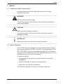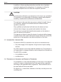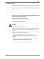
1
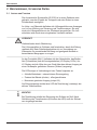
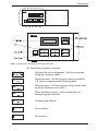
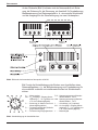
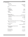
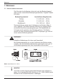
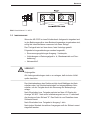
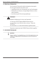
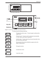
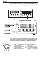
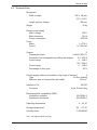
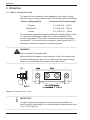
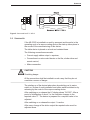
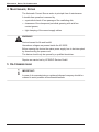
Vakuumpumpen
Instrumente
Bauteile und Ventile
LEYBOLD
VAKUUM GMBH
LEYBOLD SERVICE
GA 14.007/1
AUTOMATISCHE
STROMQUELLE
AS 053/2
AUTOMATIC
CURRENT SOURCE
AS 053/2
BEDIENUNGSANLEITUNG
OPERATING INSTRUCTIONS
INHALTSVERZEICHNIS, LIEFERUMFANG
INHALTSVERZEICHNIS
1
SICHERHEIT ............................................................................................................................................... 3
1.1 SYMBOLE FÜR SICHERHEITSHINWEISE
1.2 SICHERHEITSGRUNDSÄTZE .................................................................................................................... 3
1.3 BESTIMMUNGSGEMÄSSER GEBRAUCH - SACHWIDRIGE VERWENDUNG .................................... 4
1.4 VERHÜTUNG VON UNFÄLLEN UND VERMEIDUNG VON GERÄTESCHÄDEN ................................. 4
1.5 VERBLEIBENDE GEFÄHRDUNGEN ......................................................................................................... 5
1.6 ELEKTRISCHE SICHERHEIT .................................................................................................................... 5
2
BESCHREIBUNG, TECHNISCHE DATEN ............................................................................................... 6
2.1 AUFBAU UND FUNKTION ......................................................................................................................... 6
2.2 TECHNISCHE DATEN ............................................................................................................................... 9
3
BEDIENUNG............................................................................................................................................. 10
3.1 ANSCHLUSSWERT FESTLEGEN ........................................................................................................... 10
3.2 INBETRIEBNAHME................................................................................................................................... 11
4
WARTUNG, REPARATUR ..................................................................................................................... 12
5
AUSSERBETRIEBNAHME ...................................................................................................................... 12
EG-KONFORMITÄTSERKLÄRUNG .................................................................................................................. 13
OPERATING INSTRUCTIONS ........................................................................................................................... 14
WICHTIG!
Die Automatische Stromquelle AS 053/2 ist entsprechend der EMVRichtlinie 89/336/EWG für den bestimmungsgemäßen Gebrauch im
Industriebereich ausgelegt.
LIEFERUMFANG
Automatische Stromquelle AS 053/2 mit Gehäuse als Tischgerät,
Netzleitung mit Schutzkontakt-Stecker,
Feinsicherungen: 1 x T10 A, 1 x T200 mA,
Brücken: 4 (Messing),
Scheiben: 8 (Messing),
Sechskantmuttern: 8 (Messing),
Bedienungsanleitung.
2
Für künftige Verwendung aufbewahren!
SICHERHEIT
1 SICHERHEIT
1.1 SYMBOLE FÜR SICHERHEITSHINWEISE
In dieser Bedienungsanleitung werden folgende Symbole für
sicherheitsrelevante Hinweise verwendet:
WARNUNG!
Kennzeichnet eine möglicherweise vorhandene Gefahr.
Das Nichtbeachten dieses Hinweises kann schwere gesundheitliche
und Sachschäden hervorrufen.
VORSICHT!
Kennzeichnet eine möglicherweise gefährliche Situation.
Das Nichtbeachten dieses Hinweises kann leichte Verletzungen oder
Sachbeschädigungen bewirken.
WICHTIG!
Kennzeichnet Verwendungshinweise und andere nützliche
Informationen.
1.2 SICHERHEITSGRUNDSÄTZE
Das Gerät ist nach dem neuesten Stand der Technik, den Europanormen EN 292-1 und 292-2, den EG-Richtlinien 73/23/EWG, 89/336/EWG
und anderen geltenden sicherheitstechnischen Regeln gebaut.
Dennoch können bei seiner Verwendung Gefahren entstehen, wenn es
nicht von qualifiziertem Personal bzw. unsachgemäß bedient oder zu
nicht bestimmungsgemäßem Gebrauch eingesetzt wird.
Um zu vermeiden, daß
• Leben und Gesundheit des Bedieners oder dritter Personen
gefährdet werden;
• Funktion und Qualität des Gerätes beeinträchtigt werden;
• Sachwerte des Anwenders gefährdet werden;
sind die Hinweise dieser Bedienungsanleitung unbedingt einzuhalten.
3
SICHERHEIT
Neben der Bedienungsanleitung und den am Einsatzort geltenden
verbindlichen Regelungen zur Unfallverhütung sind auch die allgemein
anerkannten fachtechnischen Regeln für sicherheits- und fachgerechtes
Arbeiten zu beachten.
VORSICHT!
Umbauten und Veränderungen am Gerät, die nicht in dieser Bedienungsanleitung beschrieben sind, sind aus Sicherheitsgründen
verboten. Diese eigenmächtigen Veränderungen schließen eine
Haftung des Herstellers für daraus resultierende Personen- und Sachschäden aus.
Der Betreiber muß dafür sorgen, daß jede Person, die mit der Montage
bzw. Aufstellung, Erstinbetriebnahme, Bedienung und Wartung des
Gerätes beauftragt ist, diese Bedienungsanleitung gelesen und
verstanden hat.
Das Gerät darf nur von ausgebildetem und autorisiertem Personal
bedient und gewartet werden, das damit vertraut und über die Gefahren
unterrichtet ist.
Der Betreiber hat zu verhindern, daß nichtautorisierte Personen mit dem
Gerät arbeiten bzw. Handlungen vollziehen.
Der Bediener hat das Gerät mindestens einmal pro Schicht auf äußerlich erkennbare Schäden oder Mängel zu prüfen. Erkannte Veränderungen einschließlich des Betriebsverhaltens, die die Sicherheit beeinträchtigen, sind sofort dem Beauftragten des Betreibers zu melden.
1.3 BESTIMMUNGSGEMÄSSER GEBRAUCH - SACHWIDRIGE VERWENDUNG
Das Gerät AS 053/2 ist zum Gebrauch im Industriebereich bestimmt als
• Stromversorgung für Verdampfer in Hochvakuum-Bedampfungsanlagen.
Jeder darüber hinausgehende Gebrauch gilt als nicht bestimmungsgemäß. Für hieraus entstehende Schäden haftet der Hersteller nicht.
Das AS 053/2 ist verwendbar als
• Einbaugerät in einem Schaltschrank;
• Tischgerät.
1.4 VERHÜTUNG VON UNFÄLLEN UND VERMEIDUNG VON GERÄTESCHÄDEN
Schaltschrankeinbau und Einbindung des Gerätes in das elektrische
System einer Bedampfungsanlage hat durch einen Fachmann
entsprechend den VDE-Richtlinien zu erfolgen. Diese Arbeiten sind im
4
SICHERHEIT
spannungslosen Zustand von Gerät und Anlage durchzuführen.
Das Durchfassen der Lüftungsschlitze mit Fremdkörpern (z. B. Schraubendreher, Pinzette o. ä.) ist nicht gestattet.
1.5 VERBLEIBENDE GEFÄHRDUNGEN
Der vom Gerät erzeugte Strom (bis 400 A) kann durch Lichtbogen oder
starke Wärmeentwicklung einen Brand verursachen, wenn die Stromanschlüsse oder beide Leitungen je Ausgang vom Gerät zum Verdampfer
kurzgeschlossen werden oder nicht fest an den Klemmen befestigt sind.
1.6 ELEKTRISCHE SICHERHEIT
Alle netzspannungsführenden Teile befinden sich in einem geschlossenen Gehäuse. Netzanschluß und Steuerstromkreis sind getrennt
abgesichert.
Durch Einbeziehung aller Baugruppen in das Schutzleitersystem des
Gerätes wird verhindert, daß im Fehlerfall Strom durch Geräteteile fließt.
Diese Schutzwirkung darf nicht aufgehoben werden durch
• Verwendung von Netzanschluß- oder Verlängerungskabeln ohne
Schutzleiter,
• Lösen von Schutzleiterverbindungen.
WARNUNG!
Erhebliche Gefährdungen für Leben und Gesundheit!
Müssen bei Instandhaltungs- oder sonstigen Arbeiten Schutzleiterverbindungen gelöst werden, sind diese sofort nach Beendigung dieser
Arbeiten wieder herzustellen.
Weiterhin sind folgende Hinweise zu beachten:
• Es sind nur Originalsicherungen mit der vorgeschriebenen
Stromstärke zu verwenden.
• Bei Störungen in der Energieversorgung ist das Gerät sofort
abzuschalten.
• Mängel wie lose Leitungsverbindungen, angeschmorte oder
korrodierte Kabel müssen sofort nach ihrer Erkennung beseitigt
werden.
• Der geräteeigene Netzschalter kann im Dauerzustand eingeschaltet
sein, wenn das Gerät in das NOT-AUS-System und die Automatiksteuerung einer Bedampfungsanlage eingebunden ist.
5
BESCHREIBUNG
2 BESCHREIBUNG, TECHNISCHE DATEN
2.1 AUFBAU UND FUNKTION
Die Automatische Stromquelle AS 053/2 ist in einem Gehäuse untergebracht, was den Einsatz als Tischgerät oder den Einbau in einen
Schaltschrank ermöglicht.
An Unter- und Oberseite befinden sich Lüftungsschlitze zum Ansaugen
von Luft zur Kühlung von Steuerung und Transformatoren. Sie wird
durch die Lüftungsschlitze an der Rückwand ausgestoßen. Die Luftzirkulation wird durch einen eingebauten Ventilator realisiert.
VORSICHT!
Geräteschaden durch Überhitzung.
Die Lüftungsschlitze im Gehäuse sind freizuhalten, damit die Kühlung
realisiert wird. Beim Schaltschrankeinbau ist zur Vermeidung von
Wärmestau für ausreichende Belüftung und genügend Abstand zu
benachbarten Baugruppen zu sorgen.
An der Frontplatte (Bild 1) befinden sich der Netzschalter, das Bedienfeld (Folientasten) und die Anzeigeeinheiten (LC-Display, LEDs). Am
LC-Display wird die Höhe des vom Gerät über den aktiven Ausgang an
einen Verdampfer gelieferten Stromes (Sollwert) angezeigt.
Die LEDs zeigen in Verbindung mit den Tasten folgendes an:
• Aktuelle Betriebsart - externe/interne Stromregelung,
• Zustand der Blende (shutter) - offen/geschlossen.
• Momentan genutzter Ausgang (output I/II).
Als Störungsanzeige meldet eine LED die Überhitzung (overtemp) des
aktiven Transformators.
WICHTIG!
Bei Überhitzung schaltet die Steuerung den Sollwert auf Null. Nach
Abkühlung des Transformators (Erlöschen der LED) muß der Sollwert
neu eingeregelt werden.
6
BESCHREIBUNG
I
0
I
0
Bild 1: Frontseite der Automatischen Stromquelle AS 053/2
Die Tasten haben folgende Funktionen:
Wechseln des aktiven Ausganges - Die Stromversorgung
erfolgt über Ausgang I oder II.
Betriebsart extern - Die Stromregelung erfolgt automatisch
z. B. über ein angeschlossenes Ratenregelgerät.
Betriebsart intern - Die Stromregelung erfolgt manuell durch
die beiden Pfeiltasten (siehe unten).
Öffnen der Blende (shutter), die den Verdampfer vom
Bedampfungsraum abschirmt.
Schließen dieser Blende.
Strom erhöhen.
Strom senken.
7
BESCHREIBUNG
An der Rückseite (Bild 2) befinden sich der Netzanschluß mit Sicherung, die Sicherung für die Steuerung, ein Anschluß für Fernbedienung,
Blendensteuerung und Ratenregelgerät o. ä., eine serielle Schnittstelle
und die Ausgänge für die Stromversorgung von zwei Verdampfern.
Bild 2: Rückseite der Automatischen Stromquelle AS 053/2
Bild 3 zeigt die Kontaktbelegung der Buchse zum Anschließen eines
Ratenregelgerätes o. ä., der Blendensteuerung und Fernbedienung für
eine eventuell zusätzlich zu installierende Buchse bei Schaltschrankeinbau.
A .......Masse-analog
A/B ... USoll Ausgang 1; Eingang Steuerspannung, 0 ... 10 V (geliefert von
z. B. einem Ratenregelgerät)
C ......Steuerung (im Stecker immer mit
Masse-digital gebrückt)
D ......Fernsteuerung Blende (Schließer
gegen Masse-digital)
E .......Fernsteuerung Ausgangwechsel
Bild 3: Kontaktbelegung der Anschlußbuchse
8
F/G ... Spannungsversorgung Blendenantrieb Blende 2, ±24 V
H/M ..Spannungsversorgung Blendenantrieb Blende 1, ±24 V
J .......nicht belegt (+24 V optional)
A/K ... USoll Ausgang 2; Eingang Steuerspannung, 0 ... 10 V (geliefert von
z. B. einem Ratenregelgerät)
L .......Masse-digital
BESCHREIBUNG
2.2 TECHNISCHE DATEN
Abmessungen
Breite x Höhe
Tiefe (ohne Anschlußklemmen)
Masse
Elt-Anschluß
Netzspannung
Netzfrequenz
Anschlußleistung
Sicherung
Netz
Steuerung
Ausgänge (output)
Klemmen je Ausgang
446 x 135 mm
(19" x 3 HE)
400 mm
30 kg
220 V
50 Hz
2200 W
1 x T10 A
1 x T200 mA
2
4 x M10 (SW 17)
Anschlußwerte (umschaltbar durch Ändern der Brücken) 5 V / 400 A
Regelbereich
0 ... 400 A
Regelbereich
Einschaltdauer
10 V / 200 A
0 ... 200 A
20 %
Stromversorgungsleitungen (gehören nicht zum Lieferumfang)
4
Art
CU-Litze, isoliert
Mindestquerschnitt (je Leitung)
150 mm2
Schnittstelle für PC
Anschluß
Elektromagnetische Verträglichkeit (EMV)
Störaussendung
Störfestigkeit
Betriebstemperatur
RS 232
9-poliger SUB-D-Stecker
EN 50081-2
EN 50082-2
0 ... 45 °C
Lagerungstemperatur
-25 ... +70 °C
Feuchte-Klasse
F, DIN40040
9
BEDIENUNG
3 BEDIENUNG
3.1 ANSCHLUSSWERT FESTLEGEN
Die Höhe des Anschlußwertes richtet sich nach der Bedampfungsaufgabe und den verwendeten Bedampfungsmaterialien. Folgende Tabelle
soll helfen:
Bedampfungsmaterial
Anschlußwert (Regelbereich)
Wolfram
5 V / 400 A (0 ... 400 A)
Molybdän
5 V / 400 A (0 ... 400 A)
Metallkeramik
10 V / 200 A (0 ... 200 A)
Die Anschlußwerte werden durch Umklemmen der Brücken (Bilder 4
und 5) geändert. Die außen liegenden Klemmen pro Ausgang dienen
als Anschluß der Stromversorgungsleitungen. Die Kabelschuhe der
Leitungen werden zwischen zwei Scheiben geklemmt. Die Muttern
werden mit einem Schraubenschlüssel SW17 angezogen; ggf. wird mit
einem zweiten Schlüssel gekontert.
WARNUNG!
Erhebliche Gefährdungen für Leben und Gesundheit!
Bei Schaltschrankeinbau ist vor dem Umklemmen der Brücken sicherzustellen, daß alle Schaltschrankeinbauten spannungslos sind, ggf. ist
die Bedampfungsanlage durch den Hauptschalter abzuschalten.
Bild 4: Anschlußwert 10 V / 200 A
WICHTIG!
Um beide zu jedem Ausgang gehörenden Brücken stets verfügbar zu
haben, ist es zweckmäßig, beim Arbeiten mit 10 V / 200 A (Bild 4) beide
Brücken an den mittleren Klemmen zu befestigen.
10
BEDIENUNG
Bild 5: Anschlußwert 5 V / 400 A
3.2 INBETRIEBNAHME
Wenn das AS 053/2 in einen Schaltschrank fachgerecht eingebaut und
in den Bedienungszyklus einer Bedampfungsanlage eingebunden wird,
erfolgt die Inbetriebnahme zusammen mit dieser Anlage.
Das Tischgerät wird auf eine ebene, feste Unterlage gestellt.
Folgende Leitungsverbindungen werden hergestellt:
• Stromversorgungsleitungen Ausgang - Verdampfer,
• Verbindungen zu Ratenregelgerät o. ä., Blendenantrieb und Fernbedienung,
• Netzanschluß.
VORSICHT!
Stolpergefahr.
Alle Leitungsverbindungen sind so zu verlegen, daß sie keine Unfallquelle darstellen.
Das Inbetriebnehmen des Gerätes erfolgt durch Betätigen des Netzschalters oder, bei Schaltschrankeinbau und eingeschaltetem Netzschalter, mit der Freigabe durch die Steuerung der Bedampfungsanlage.
Nach Einschalten bzw. Freigabe erscheint auf dem LC-Display die
Anzeige "AS 053". Nach einer Initialisierungszeit von ca. 3 s wechselt
die Anzeige auf den Sollwert "0". Das Gerät ist zum Einstellen eines
Sollwertes bereit.
Nach Einschalten bzw. Freigabe ist Ausgang 1 aktiv.
Nach jedem Wechsel des aktiven Ausganges muß der Sollwert erneut
eingestellt werden.
11
WARTUNG, REPARATUR, AUSSERBETRIEBNAHME
4 WARTUNG, REPARATUR
Die Automatische Stromquelle arbeitet weitestgehend wartungsfrei.
Ein störungsfreier Betrieb wird realisiert durch
• regelmäßiges Prüfen der Lüftungsschlitze auf freie Durchlässigkeit,
• Sauberhalten der Klemmen und regelmäßiges Einfetten mit säurefreiem Kontaktfett,
• feste Klemmung der Stromversorgungsleitungen.
WARNUNG!
Erhebliche Gefährdungen für Leben und Gesundheit!
Im Innern der AS 053/2 liegen gefährliche Spannungen an.
Vor dem Öffnen ist das Gerät vom Netz zu trennen - Ziehen der
Netzleitung.
Das Gerät darf nur von einem Elektrofachmann geöffnet werden.
Reparaturen werden durch die LEYBOLD Service GmbH ausgeführt.
5 AUSSERBETRIEBNAHME
WICHTIG!
Wegen möglicher Umweltgefährdungen ist bei Außerbetriebnahme des
Gerätes ein zugelassenes Fachunternehmen mit der Entsorgung zu
beauftragen.
12
EG-KONFORMITÄTSERKLÄRUNG
EG-Konformitätserklärung
entsprechend der EMV-Richtlinie 89/336/EWG, Anhang I
Wir,
LEYBOLD SERVICE GMBH,
Königsbrücker Landstraße 159 / Haus 133, D-01109 Dresden,
erklären in alleiniger Verantwortung, daß das Produkt
Automatische Stromquelle AS 053/2,
Sachnummer 200 23 209/2,
auf das sich diese Erklärung bezieht, den einschlägigen grundlegenden Sicherheits- und
Gesundheitsanforderungen der EG-Richtlinien
- Niederspannung 73/23/EWG
- Elektromagnetische Verträglichkeit 89/336/EWG
sowie den Anforderungen der folgenden einschlägigen harmonisierten Normen:
EN 292 : 1991 Sicherheit von Anlagen; Grundbegriffe, allgemeine Gestaltungsleitsätze
ENV 26 385 Prinzipien der Ergonomie in der Auslegung von Arbeitssystemen
(ISO 6385 : 1981)
entspricht.
Zur sachgerechten Umsetzung der in den EG-Richtlinien genannten Sicherheits- und
Gesundheitsanforderungen wurde folgende Vorschrift herangezogen:
VDE 0113 : 1986 Sicherheit von Anlagen; Elektrische Ausrüstung von Anlagen
Dresden, 29.03.1996
Dr. Großmann
Geschäftsführer
Dipl.-Ing. Willkommen
Prokurist
13
CONTENTS, STANDARD SPECIFICATION
CONTENTS
1
SAFETY .................................................................................................................................................... 15
1.1 SYMBOLS FOR SAFETY INSTRUCTIONS ............................................................................................ 15
1.2 SAFETY PRINCIPLES ............................................................................................................................. 15
1.3 INTENDED USE - IMPROPER USE ...................................................................................................... 16
1.4 PREVENTION OF ACCIDENT AND DAMAGE TO PROPERTIES ....................................................... 16
1.5 REMAINING HAZARDS ........................................................................................................................... 17
1.6 ELECTRICAL SAFETY ............................................................................................................................ 17
2
DESCRIPTION, TECHNICAL DATA ...................................................................................................... 18
2.1 DESIGN AND FUNCTION ....................................................................................................................... 18
2.2 TECHNICAL DATA .................................................................................................................................. 21
3
OPERATION ............................................................................................................................................. 22
3.1 SELECT A CONNECTED LOAD ............................................................................................................ 22
3.2 STARTING-UP ......................................................................................................................................... 23
4
MAINTENANCE, REPAIR ....................................................................................................................... 24
5
DE-COMMISSIONING ............................................................................................................................. 24
EC DECLARATION OF CONFORMITY ........................................................................................................... 25
BEDIENUNGSANLEITUNG .................................................................................................................................. 2
CAUTION!
The Automatic Current Source AS 053/2 is designed for the intended
use in an industrial area according to the EMC guideline 89/336/EEC.
SCOPE OF DELIVERY
Automatic current source AS 053/2 with housing,
Power cord with earthing-contact plug,
Miniature fuses: 1 x T10 A, 1 x T200 mA,
Bridges: 4 (brass),
Washers: 8 (brass),
Hexagon nuts: 8 (brass),
Operating instructions.
14
Keep for further use!
SAFETY
1 SAFETY
1.1 SYMBOLS FOR SAFETY INSTRUCTIONS
In these operation instructions the following symbols for safety
instructions are used:
WARNING!
Marks a possibly existing danger.
The non-observance of this instruction may cause heavy damage to
health and properties.
CAUTION!
Marks a possibly dangerous situation.
The non-observance of this instruction may cause light injuries or
damage to property.
IMPORTANT!
Marks instructions of use and other helpful information.
1.2 SAFETY PRINCIPLES
The AS 053/2 has been designed and constructed to state-of-the-art,
the European standards EN 292-1 and 292-2, the EU-guidelines 73/23/
EEC, 89/336/EEC as well as other applying safety rules. Nevertheless,
its use may cause danger if the device is operated improperly or by nonqualified personnel or if not used as agreed.
In order to avoid that
• life and health of the operator or people indirectly involved are
endangered;
• function and quality of the device are deteriorated;
• properties of the user are endangered,
it is absolutely necessary to follow the operating instructions.
15
SAFETY
In addition to these operating instructions and the rules of accident
prevention applying at the using place, it is necessary to follow the
generally accepted rules of a safe and competent operation.
CAUTION!
Unauthorized modifications and alterations of the device are prohibited.
The producer is not responsible for damage to people and properties
caused by unauthorized modifications and alterations.
The user has to take care that every person ordered to install, first put
into operation, operate and maintain read and understood these
operation instructions.
Only qualified and authorized staff who know the device and are
informed about danger may operate and maintain the device.
The user has to prevent that unauthorized people use the device or
carry out actions on the device.
The operator is obliged to check the device for external visible damage
or faults at least once a shift. Observed changes which may reduce the
safety have to be reported to the authorized person of the user.
1.3 INTENDED USE - IMPROPER USE
The device AS 053/2 is intended to be used in an industrial area as
• the power supply for the vaporizer in high vacuum vapour coating
devices.
Any other actions do not comply with the intended use. The producer is
not responsible for damage caused by actions beyond the intended use.
The AS 053/2 is suitable
• for installation in a rack,
• as table device.
1.4 PREVENTION OF ACCIDENTS AND DAMAGE TO PROPERTIES
The installation in a rack and the binding-in of the device in the electrical
system of a vapour coating device has to be executed by a specialist
according to the applicable safety regulations. These activities have to
be made while all devices are dead.
No objects (e. g. screw-driver, tweezers or the like) must be put into the
ventilating slits.
16
SAFETY
1.5 REMAINING HAZARDS
The current produced by the device (up to 400 A) may cause a fire by an
arc or by strong heating if the connections or both leads per output from
the device to the vaporizer have a short-circuit or if they are not attached
tightly to the clamps.
1.6 ELECTRICAL SAFETY
All areas containing live electric parts are covered. The mains
connection and the controlling current circuit are fused separately.
Inclusion of all components in the earthing system prevents parts of the
device from being live in case of fault.
This precaution must not be cancelled by
• use of an extension lead without earthing wire,
• removing earthing connections.
WARNING!
Serious hazard for life and health!
If the earthing connections have to be removed during maintenance or
other work they shall be connected immediately after the end of these
activities.
Furthermore, note the following instructions:
• Use only original fuses with the required amperage.
• Switch off the device immediately in case of faults in the power
supply.
• Defects like slack connections, braised or corroded wires have to be
repaired immediately after having been observed.
• The device´s mains switch may be switched on permanently if the
device is bound in the emergency stopping system or the automatic
control system of a vapour coating device.
17
DESCRIPTION
2 DESCRIPTION, TECHNICAL DATA
2.1 DESIGN AND FUNCTION
The Automatic Current Source AS 053/2 is placed in a housing so that it
may be used as a table device or installed in a rack.
On top and bottom, ventilating slits are placed through which air is
drawn in to cool the control and transformer. This air is exhausted
through the slits in the device´s back face. Ventilating is carried-out by a
built-in ventilator.
CAUTION!
Damage to property by overheating.
The device´s ventilating slits have to be kept free to perform the cooling.
To avoid heat build-up when installed in a rack care should be taken for
sufficient ventilation and distance to neighbouring instruments.
At the front face (figure 1) the mains switch, the operating area (film
keys) and the indicating units (LC display, LEDs) are placed.
The LC display shows the value of the current (required value) delivered
from the device´s active output to a vaporizer.
In connection with the keys the LEDs show:
• Present operation - external/internal current control,
• Status of the shutter - open/close,
• Output used actually (I or II).
As a failure indication an LED indicates the overheat (overtemp) of the
active transformer.
IMPORTANT!
In case of overheat the required value is switched to zero by the control.
After transformer´s cooling (LED goes out) the required value must be
adjusted anew.
18
DESCRIPTION
I
0
I
0
Figure 1: Front face of the Automatic Current Source AS 053/2
The keys have the following functions:
Changing the active output - Current supply is performed by
output I or II.
External mode - Current control is performed automatically,
e. g. by a rate control device connected.
Internal mode - Current control is performed manually by the
two arrow keys (see below).
Opening the shutter which shields the vaporizer from the
vapour coating space.
Closing this shutter.
Increase the current.
Lower the current.
19
DESCRIPTION
At the rear side (figure 2) the mains connection with its fuse, the fuse of
the control, a connection socket for the remote control, shutter control
and rate control device, a connection for RS 232 interface and the
outputs for the current supply of two vaporizers are placed.
Figure 2: Rear side of the Automatic Current Source AS 053/2
Figure 3 shows the contact assignment of the socket to connect a rate
control device or the like, the shutter control and the remote control for
possible mounting of an additional socket in case of rack installation.
A .......Mass-analog
A/B ... Urequ. output 1; Input controlling
voltage, 0 ... 10 V (delivered by e.
g. a rate control device)
C ......Control (permanently bridged with
mass-digital in the plug)
D ......Remote control shutter (closer to
mass-digital)
E .......Remote control output change
Figure 3: Contact assignment of the connection socket
20
F/G ... Power supply shutter drive,
shutter 2, ±24 V
H/M ..Power supply shutter drive,
shutter 1, ±24 V
J .......not assigned (+24 V optional)
A/K ... Urequ. output 2; Input controlling
voltage, 0 ... 10 V (delivered by
e. g. a rate control device)
L .......Mass-digital
TECHNICAL DATA
2.2 TECHNICAL DATA
Dimensions
Width x height
446 x 135 mm
(19" x 3 HU*)
Length (without clamps)
400 mm
Weight
30 kg
Electric power supply
Mains voltage
Mains frequency
Power consumption
220 V
50 Hz
2200 W
Fuses
Mains
Control
Outputs
Clamps per output
1 x T10 A
1 x T200 mA
2
4 x M10 (SW 17)
Connected load (changeable by shifting the bridges)
Control range
Control range
Percentage of duty cycle
5 V / 400 A
0 ... 400 A
10 V / 200 A
0 ... 200 A
20 %
Current supply cables (not included in the scope of delivery)
4
Type
Cu-flex, isolated
Minimum area of cross section (per cable)
150 mm2
Interface to PC
Connector
Electromagnetic compatibility (EMC)
Interference radiation
Interference resistance
Operating temperature
RS 232
9-pin, D-shell, plug
EN 50081-2
EN 50082-2
0 ... 45 °C
Storage temperature
-25 ... +70 °C
Humidity class
F, DIN40040
*
HU = unit height (modular spacing)
21
OPERATION
3 OPERATION
3.1 SELECT A CONNECTED LOAD
The amount of the connection value depends on the vapour coating
task and vapour coating materials used. The following table should help:
Vapour coating material
Connected load (control range)
Tungsten
5 V / 400 A (0 ... 400 A)
Molybdenum
5 V / 400 A (0 ... 400 A)
Cermet
10 V / 200 A (0 ... 200 A)
The connected loads are changed by shifting the bridges (figures 4 and
5). The external clamps per output serve for the connection of the
current supply cables. The cable´s connectors are clamped between
two washers. The nuts are fixed by a spanner (width across flats 17); if
necessary counteract by means of a second spanner.
WARNING!
Serious hazard for life and health!
Before shifting the bridges in rack installation it has to be ensured that
all rack installed devices are not live; if necessary the vapour coating
device is to be switched off by means of its mains switch.
Figure 4: Connected load 10 V / 200 A
IMPORTANT!
In order to have both bridges per output permanently available it is
useful to attach both bridges to the central clamps during operation with
10 V / 200 A (figure 4).
22
OPERATION
Figure 5: Connected load 5 V / 400 A
3.2 STARTING-UP
If the AS 053/2 is installed in a rack by an expert and bound-in in the
operating cycle of a vapour coating device, the start-up takes place in
the course of the commissioning of this device.
The table device is placed on a level and resistant base.
The following connections are made:
• Current supply cables output ≡ vaporizer,
• Connections to a rate control device or the like, shutter drive and
remote control,
• Mains connection.
CAUTION!
Stumbling danger.
All the connections shall be installed in such a way that they do not
constitute a source of danger.
The starting-up of the device takes place by switching-on its mains
switch or, in case of rack installation and mains switch switched-on by
releasing by the control of the vapour coating device.
After switching-on or release the LC display shows "AS 053". After a
period of initialisation of about 3 s, the indication changes to the
required value "0". The device is prepared for a required value to be
adjusted.
After switching on or release the output 1 is active.
After every change of the aktive output the required value must be
adjusted anew.
23
MAINTENANCE, REPAIR, DE-COMMISSIONING
4 MAINTENANCE, REPAIR
The Automatic Current Source works in principle free of maintenance.
A trouble-free operation is ensured by
• a periodical check of free passage of the ventilating slits,
• cleanness of the clamps and periodical greasing with acid-free
contact grease,
• tight clamping of the current supply cables.
WARNING!
Serious hazard for life and health!
Hazardous voltages are present inside the AS 053/2.
Before opening the device the mains power supply has to be interrupted
by disconnecting the power cord.
The device should only be opened by a qualified electrician.
Repairs are carried out by LEYBOLD Service GmbH.
5 DE-COMMISSIONING
IMPORTANT!
In case of de-commissioning a registered disposal company should be
ordered to avoid possible environmental hazards.
24
EC DECLARATION OF CONFORMITY
EC Declaration of Conformity
as defined by EMC-directive 89/336/EEC Annex I
Herewith we,
LEYBOLD SERVICE GMBH,
Königsbrücker Landstraße 159 / Haus 133, D-01109 Dresden,
declare that the product
Automatic Current Source AS 053/2,
Product number 200 23 209/2
complies with the following EC guidelines applying to it:
- Low Voltage Directive 73/23/EEC
- Electromagnetic Compatibility Directive 89/336/EEC
Applied harmonized standards in particular:
EN 292:1991 Safety of machinery; basic concepts, general design principles
ENV 26 385 Principles of ergonomy in the design of working systems (ISO 6385 : 1981)
In order to comply with the safety and health requirements designated in the EC
guidelines the following regulation was applied:
VDE 0113:1986 Safety of installations; electric equipment of installations
Dresden, 29.03.1996
Dr. Großmann
Manager
Dipl.-Ing. Willkommen
Authorized signatory
25
04.96
Nach Unterlagen und Informationen des
Herstellers erarbeitet von:
Dipl.-Ing. Gerd Wetzig - Technischer Redakteur Königsbrücker Landstraße 8
D-01478 Weixdorf
Tel./Fax (03 51) 8 80 57 17
LEYBOLD Service GmbH
Königsbrücker Landstraße 159 / Haus 133
D-01109 Dresden
Telefon: (03 51) 8 85 50-0
Telefax: (03 51) 8 85 50-41
Printed in Germany on chlorine-free bleached paper
1.80.6.639.05 CD
IMPRESSUM