1
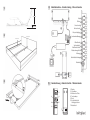
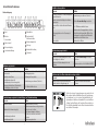
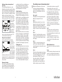
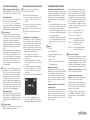
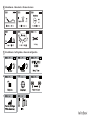
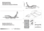
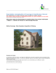
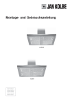
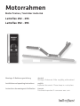
Motorrahmen Motor frames / Sommier motorisé Lattoflex 292 - 295 Lattoflex 392 - 395 Montage- & Bedienungsanleitung deutsch Installation and operating instructions english Instructions de montage et d’utilisation français Document important. A conserver avec soin. Wichtiges Dokument. Bitte sorgfältig aufbewahren! Important document. Please keep in a safe place. 4 1 Inbetriebnahme – Commissioning – Mise en Service ca. 70 cm Kopf 1 9 Rücken 2 Oberschenkel 3 ca. 13 cm 1 Unterschenkel 4 Körperschräglage 5 2 2 Lendenunterstützung max. 8 cm max. 4 cm 6 Wärmflasche 7 Synchronkabel/ 8 Kabelhandschalter Notabsenkungsblock 9 4 3 Massage 10 Unterbettbeleuchtung 11 Netzkabel 12 3 5 Fernbedienung – Remote Control – Télécommande 1 – Display 2 – Steuerkreuz 3 – Menüwechsel-Taste 4 – Taschenlampe 5 – Reset 6 – Komforttasten für Lieblingspositionen 7 – Batteriefach 1 3 2 4 5 6 7 4 Sie haben ein Smartphone? Bitte nutzen Sie die kostenlose LattoflexApp zur Steuerung Ihres Motorrahmens – auch quer durch’s Haus solange Sie in Ihrem W-LAN-Netz sind. Laden Sie die LattoflexApp für iPhone oder iPad bei itunes runter, für Android-Geräte bei Google Play. Folgen Sie einfach dem QR-Code: Have you got a smart phone? Please use the free Lattoflex app to control your motor frame - even throughout the house as long as you are in the Wi-Fi network. Load the Lattoflex app for iPhone or iPad from itunes, or from GooglePlay for android devices. Simply follow the QR code: Vous possédez un Smartphone ? Alors veuillez utiliser l’appli Lattoflex gratuite pour commander votre sommier motorisé – même à travers la maison, tant que vous êtes connecté à votre réseau WIFI. Téléchargez l’appli Lattoflex pour iPhone ou iPad sur iTunes, pour Android sur Google Play. Il vous suffit de suivre le code QR. Inhaltsverzeichnis Montage und Anschluss.................................................................................................. 4 Die Lattoflex Fernbedienung............................................................................................ 5 Einstellungen vornehmen und speichern........................................................................... 6 Notabsenkung................................................................................................................ 6 Sicherheitshinweise........................................................................................................ 6 Pflegehinweise............................................................................................................... 6 Einstellmenü.................................................................................................................. 7 Erste Hilfe bei Problemen........................................................................................... 8 - 9 Baubiologische Gesichtspunkte..................................................................................... 22 Technische Daten......................................................................................................... 23 Bitte beachten Sie die Aufklappseiten vorne und hinten. Contents Zur Verbindung mit dem Motorrahmen benötigen Sie den W-LAN-Adapter „Smart Remote“ (als Zubehör erhältlich). You will need the Smart Remote Wi-Fi adapter to connect with the motor frame (available as accessory). Pour vous connecter au sommier motorisé, vous devez disposer de l’adaptateur WIFI « Smart Remote » (disponible comme accessoire). Installation and connection............................................................................................ 10 The Lattoflex remote control......................................................................................... 11 Adjusting and saving the settings................................................................................... 12 Emergency lowering..................................................................................................... 12 Safety instructions........................................................................................................ 12 Care instructions.......................................................................................................... 12 Settings menu.............................................................................................................. 13 Troubleshooting.................................................................................................... 14 - 15 Ecological aspects....................................................................................................... 22 Technical data.............................................................................................................. 23 Please note the front and back fold-out pages. Sommaire Montage et raccordement............................................................................................. 16 La télécommande Lattoflex .......................................................................................... 17 Configurations et enregistrements................................................................................. 18 Abaissement de secours............................................................................................... 18 Consignes de sécurité.................................................................................................. 18 Conseils d‘entretien...................................................................................................... 18 Menu de configuration.................................................................................................. 19 Remèdes en cas de pannes .................................................................................. 20 - 21 Aspects écobiologiques du bâtiment ............................................................................. 22 Caractéristiques techniques.......................................................................................... 23 Veuillez observer les pages à déplier à l‘avant et à l‘arrière. Montagehinweise Rahmentyp und Seriennummer Das Typenschild finden Sie am Kopfende auf dem linken Längsholm unter der Kopfhoch lagerung. 4 2 Bitte gehen Sie zur Inbetriebnahme Ihres Motorrahmens wie folgt vor: Bidirektionale Funkverbindung 2 Netzgerät an die Steuerung anschließen, Steckersicherung aufclipsen. - 3 Motorrahmen ans Stromnetz anschließen. 4 Fernbedienung auspacken und Batterien einlegen. Einlegen in ein Bett/Bodenfreiheit: Bitte berücksichtigen Sie den notwendigen Platzbedarf für die verstellbaren Rahmenteile z.B. bei Dachschrägen, Bettüberbauten oder gepolsterten Kopfteilen. Für die Verstell mechanik und Antriebstechnik im Unterbau wird eine Einbautiefe (Bodenfreiheit) von ca. 14 cm benötigt. Bitte beachten Sie immer den Abstand des motorisch verstellbaren Rückenteils zum Kopf teil des Bettes. In Flachlage sollte hier ein Abstand von mindestens 1,5 cm bestehen. Um ein unbeabsichtigtes Verrutschen auszuschließen, den Rahmen bitte an vorgebohrten Punkten im Metallunterbau mit dem Bett verschrauben. Anlernen der Fernbedienung: Nach dem ersten Einlegen der Batterien erscheint das Display zur Sprachwahl: Bitte wählen Sie Deutsch, Englisch oder Französisch durch Drücken der Mitteltaste im Steuerkreuz aus. Anschließend befindet sich die Fernbedienung automatisch im Menü zum Anlernen eines Motorrahmens: 1. Den Suchmodus durch Drücken der Mitteltaste im Steuerkreuz auslösen. 2. Innerhalb von 30 Sekunden den Taster auf dem Notabsenkungsblock kurz drücken. 3. Die Fernbedienung bestätigt das erfolg reiche Anlernen mit „Erfolgreich“, die Steuerung im Motorrahmen piept. Seitliche Auflageleisten dürfen maximal 4 cm breit sein (Mittelzarge 8 cm). Der Motorrahmen muss immer spannungsfrei ins Bett passen. Bei Betten mit Dreiecksauflagen (Schenkellänge max. 15 cm) bitte den Einbausatz „Verlängerungselemente“ verwenden (als Zubehör erhältlich). Wir empfehlen für eine stabile Bettkonstruktion bei Dreiecksauflagen immer einen Auflagepunkt in der Bettseitenmitte. 4. Auf dem Display erscheint automatisch die Aufforderung zur Initialisierung: 5. Um den Anlernvorgang abzuschließen die Taste R so lange drücken, bis auf dem Display die Motorrahmenabbildung erscheint. Matratzenhalter Den mitgelieferten Halter am Fußende anbringen. Die Kunststoffschellen sind vormontiert. 4 Auf den 6 Komforttasten sind bei Auslieferung Voreinstellungen hinterlegt. Damit kommen Sie schnell in den Genuss des kompletten Funktionsumfanges. Die Voreinstellungen sind jederzeit änderbar und durch eigene Lieblingseinstellungen ersetzbar (s. Seite 6, Einstellungen speichern). Bei Motorverstellung: Die jeweilige Nummerntaste so lange gedrückt halten, bis der Rahmen seine Endposition erreicht hat. Mit Ihrem Motorrahmen wurde eine intelligente Funk-Fernbedienung ausgeliefert. Zwischen der Fernbedienung und der Steuereinheit im Motorrahmen besteht eine bidirektionale, also beidseitige Funkverbindung. Das hat zwei entscheidende Vorteile: Steuerung anschließen. Ggf. alle weiteren Zubehörteile anschließen. Antirutschfolie An den Auflagepunkten des Rahmens im Bettgestell anbringen. Die Folien verhindern Geräusche, die durch Verrutschen der Rahmen im Bettgestell entstehen können. 3 Die Lattoflex Fernbedienung 1 Notabsenkungsblock an Buchse 9 der Mitgeliefertes Zubehör Montagezubehör: Matratzenhalter (Fußende), 4 Antirutschfolien Anschlusszubehör: Funk-Fernbedienung mit Batterien (3 x AAA), Filztasche, Notab senkungsblock, Netzgerät, Zuleitungskabel, Steckersicherung 1 Anschluss und Inbetriebnahme - 5 Es werden nur Motoren und Zubehörteile angezeigt, die in Ihrem Rahmen installiert sind. Nachträglich angeschlossene Komponenten werden nach einem erneuten Anlernvorgang automatisch im Menü der Fernbedienung ergänzt. Taste 1 = Lese- und Sitzposition Taste 2 = Beinhochlagerug Taste 3 = Relaxposition Im Display wird zu jeder Zeit die genaue Position aller Verstellteile und der Funk tionsstatus aller Zubehörteile angezeigt. Taste 4 = Licht an/aus (Stufe 3/10min), Option Taste 5 = Steckdose an/aus, Option Übersicht Taste 6 = Wärmflasche an/aus (Stufe 3/15min), Option 1 – Display 2 – Steuerkreuz 3 – Menüwechsel-Taste (Mitteltaste) 6 4 – Taschenlampe 5 – Reset 6 – Komforttasten für Lieblingspositionen 7 – Batteriefach Batteriewechsel Bitte halten Sie Batterien zum Wechseln bereit, sobald die Akkuanzeige nur noch einen roten Balken anzeigt. Es werden 3 Batterien oder 3 aufladbare Akkus der Größe AAA benötigt. Einfach den Batteriefachdeckel auf der Rückseite aufschieben. Auf korrekte Polarität achten. Menü-Übersicht Die Lattoflex-Fernbedienung vereint die Steue rung der Motorverstellungen und aller installierten Lattoflex-Komponenten in nur einer Bedieneinheit. Je nach installierten Antrieben und Funktionskomponenten erscheinen auf der Fernbedienung die verschiedenen Ebenen laut Abb. 6. Wechsel zwischen den Ebenen: fortlaufend durch die „Menüwechsel-Taste“. Rücksprung auf die Motorverstellebene: Immer mit kurzem Tastendruck auf die RTaste „Reset“. Durch Bewegung oder einen Tastendruck wird die Fernbedienung eingeschaltet. Nach dem Lattoflex-Logo ist immer die Motorverstellung zu sehen. Schnellstart Motorrahmenbedienung Die Fernbedienung schaltet sich bei Bewegung oder bei Tastendruck selbstständig ein. Wird für eine Dauer von 10 Sekunden keine Einstellung vorgenommen oder die Fernbedienung nicht bewegt, schaltet sie sich in den Schlaf-Modus. Unterbettbeleuchtung, Steckdosenempfänger und Wärmflasche sind als Zubehör erhältlich. Bitte wenden Sie sich an Ihren LattoflexFachhändler. 5 Einstellungen vornehmen und bei Bedarf speichern Die Menüwechsel-Taste führt im Rundlauf durch die verschiedenen Funktionen und das Einstellmenü. Ist die gewünschte Funktion erreicht, einfach mit den Tasten „Rechts“ oder „Links“ das einzustellende Element auswählen. Dann mit den Tasten „Hoch“ und „Runter“ die Einstellung vornehmen. In jeder Menüebene kommt man auf die „Memory“-Ansicht (mehrfach Taste „Rechts“ oder „Links“ drücken). Hier können Sie die gerade vorgenommenen Einstellungen als Lieblingsposition abspeichern. Dazu im Memory modus eine der sechs Komfort tasten 2 Sekunden gedrückt halten. Zur Bestätigung piept die Steuerung im Motor rahmen. die Motoren sehr langsam und hintereinander zurück. Bitte beachten Sie, dass die Batterien bei Verwendung der Notabsenkung fast entleert werden und anschließend ausgetauscht werden müssen (2 x 9 V E Block). Sicherheitshinweise Beim Betätigen und im hochgestellten Zustand nicht auf den Rahmen steigen. Der Rahmen ist so konstruiert, dass bei Betätigung normalerweise keine Einklemm- oder Quetschgefahr besteht. Achten Sie trotzdem darauf, dass sich bei Betätigung des Rahmens keine Personen, insbesondere keine Kinder unter dem Rahmen befinden oder in den Mechanismus hineingreifen. Lattoflex 292-295, 392-395 und baugleiche Modelle sind Einlegerahmen für Bettgestelle. Die Nutzung ist nur nach den Maßgaben dieser Anleitung und nur für den Hausgebrauch vorgesehen. Niemals die Kabel einklemmen, scharfkantig verlegen oder durch bewegliche Rahmenteile quetschen. Beschädigte Anschlussleitungen nur gegen Originalteile ersetzen. Beschädigungsgefahr durch Kürzen der Tragholme oder durch Demontage von Beschlagteilen. Verstauen Sie keine Gegenstände unter dem Rahmen. Besonders Bettwäsche kann durch die Motoren Schaden nehmen. Beispiel Rahmenverstellung Mit den Pfeil tasten „Rechts“ und „Links“ das zu bewegende Rahmenteil auswählen. Das ausgewählte Element ist an der gelben Markierung erkennbar. Verstellung mit den Pfeiltasten „Hoch“ und „Runter“. Die Tasten so lange gedrückt halten, bis die Motoren die gewünschte Stellung erreicht haben. Durch langes Drücken der Taste R fahren alle Motoren gleichzeitig in die Flachlage. Reinigung und Pflege Ihre Lattoflex Unterfederung braucht keine besondere Pflege. Es genügt, wenn Sie sie einfach ab und zu mit einem feuchten Tuch abwischen. Bitte verwenden Sie weder Lösungsmittel oder Benzin, noch ätzende oder scheuernde Mittel. Immer den Netzstecker während der Reinigung aus der Steckdose ziehen. Gelegentlich auftretende Geräusche an den Laufflächen der Schiebefunktion oder an Kunststofflagern können mit Silikon oder besser mit Flonium behandelt werden. Benutzen Sie in keinem Fall handelsübliche Öle oder Fette. Notabsenkung Bei Stromausfall können die Motoren über den Taster auf dem Notabsenkungsblock in die Flachlage verstellt werden. Hierbei fahren 6 Das Einstellmenü in der Fernbedienung 7 Je nach Bedarf können alle Funktionen und Parameter der Fernbedienung eingestellt und angepasst werden. Bitte vergleichen Sie diese Beschreibung mit den Abbildungen auf der hinteren Aufklappseite. Anlernen am Motorrahmen: siehe Seite 4. Anlernen am Steckdosenempfänger: Mit der Menüwechseltaste „Suche“ auswählen, den Codierschalter am Steckdosenempfänger auf POS B (Einlernen, nach rechts) stellen, den gewünschten Kanal an der Fernbedienung auswählen und mit der Menüwechseltaste bestätigen. Standardmäßig wird der nächste freie Kanal gewählt (max. 6). Den Codierschalter am Steckdosenempfänger wieder auf POS A (Betrieb, nach links) stellen. Die Inbetriebnahme ist damit abgeschlossen. Siehe auch separate Anleitung. Abbildungen 1 und 2: Helligkeit von Display und Tastaturbeleuchtung kann 6-stufig angepasst werden. Abbildung 3: Uhrzeit und Datum einstellen. Um in den Einstellmodus zu gelangen, bitte hier die Menüwechsel-Taste drücken. Nach erfolgten Einstellungen ebenso. Mit den 4 Pfeiltasten alle Einstellungen vornehmen. Anschließend wieder die Menüwechseltaste drücken. Abbildung 7: Um die Fernbedienung auf Werkseinstellung zurückzusetzen wie folgt vorgehen: Durch Drücken der Menüwechsel-Taste auswählen und die nächste Abfrage mit Ja bestätigen. Jetzt müssen alle Geräte neu angelernt werden, siehe Seite 4, Anlernen der Fernbedienung. Datum und Uhrzeit bleiben erhalten. Abbildung 4: Kindersicherung, zum Aktivieren und Deak tivieren die Menüwechsel-Taste mindestens 10 Sekunden gedrückt halten. Der Status wird im Display durch das Schloßsymbol angezeigt. Abbildung 5: Sprache: Um die Sprache zu ändern bitte die Menüwechsel-Taste drücken. Gewünschte Sprache einstellen und mit MenüwechselTaste bestätigen. Ohne Abbildung: Test Dieser Punkt beinhaltet keine relevanten Funktionen. Abbildung 8: Info: Hier werden Softwarestand und Seriennummer angezeigt. Bei technischen Rück fragen diese Informationen bereithalten. Abbildung 6: Teach in / out: Nach Drücken der Menüwechseltaste kann man mit den Pfeiltasten „Rechts“ oder „Links“ folgende Funktionen auswählen: „Suche“ (neues Gerät anlernen), „Entfernen“ (eingelerntes Gerät entfernen) oder „Verlassen“ (hiermit verlässt man den Teach in / out – Bereich). Die gewünschte Funktion mit der Menüwechseltaste auswählen und ggf. den Display anweisungen folgen. 7 Erste Hilfe bei Problemen Ein Motor ist ausgefallen Ursache Buchsenbelegung 12 1 2 3 4 5 6 7 8 9 10 1 Kopf 7 Wärmflasche 2 Rücken 8 Synchronkabel/ 11 Kabelhandschalter 3 Oberschenkel 9 Notabsenkungsblock 4 Unterschenkel Abhilfe Der Motor kann auf der Fernbedienung nicht angewählt werden. Stecker steckt nicht richtig in der Buchse / ausgezogen. Einzelner Motor ist überhitzt durch Dauerbetrieb. Fernbedienung neu anlernen (Teach In). Stecker bis zum Anschlag einstecken. Ca. 20 Minuten auskühlen lassen. Motor in andere Ausgangsbuchse stecken. Siehe Buchsenbelegung links. Mit der Fernbedienung das entsprechende Rahmenteil auswählen und den Motor testen. Austausch des Motors 1 Ausgangsbuchse an der Steuerung ist defekt. Motor defekt 10 Massage 5 Körperschräglage 6 Lendenunterstützung 11 Unterbettbeleuchtung Notabsenkung reagiert nicht 12 Netzkabel Ursache Abhilfe Stecker vom Notabsenkungsblock steckt nicht richtig in der Buchse. Batterien im Notabsenkungsblock sind entladen. Stecker bis zum Anschlag in Buchse 9 einstecken. Rahmen reagiert nicht Ursache Netzstecker gezogen / Netzzuleitung unterbrochen. Steckdose ohne Strom. Fernbedienung vertauscht. Fernbedienung nicht mehr angelernt. Steuerung überhitzt durch Dauerbetrieb. Bei Betätigung ertönt ein Piepton. Abhilfe Netzstecker einstecken / Steckverbindungen am Netzgerät prüfen. Sicherung im Haus prüfen. Fernbedienung neu anlernen (Teach In). Batterien wechseln, 2 x 9-Volt-Block (6LR61) Rücken- und/oder Oberschenkelmotor senken nicht ab Ursache Abhilfe Rahmen stößt auf einen Widerstand und schaltet durch die Zugsicherung ab. Motoren hoch fahren und Widerstand entfernen. Ca. 20min abkühlen lassen. Fernbedienung reagiert nicht, keine Display- und Tastenbeleuchtung Ursache Abhilfe Batterien entladen. Batterien wechseln, 3 x AAA. Batterien herausnehmen, richtig einsetzen. Dabei auf + und – achten. Siehe Kennzeichnung im Gehäuse. Eine Batterie entnehmen und wieder einsetzen. Fernbedienung tauschen. Batterien falsch herum eingelegt. Fernbedienung deaktiviert. Fernbedienung defekt. 8 Sollten Sie zu keiner Lösung gekommen sein, wenden Sie sich bitte an Ihren Lattoflex-Fachhändler. Wenn die Fernbedienung noch funktioniert, so ist es in jedem Problemfall hilfreich, die Systemdaten an Lattoflex zu übermitteln. Diese sind im Menü „Settings“ auf dem Display „Info“ zu finden. Wenn möglich ein Foto des Bildschirminhalts senden. Diese Informationen helfen zur schnellen Fehleranalyse. 9 Installation instructions Frame type and serial number The name plate is located at the head end on the left longitudinal beam below the raised head. 4 2 Please proceed as follows to commission your motor frame: Bi-directional radio connection Your motor frame has been delivered with an intelligent radio remote control. There is a bi-directional i.e. two-sided radio connection between the remote control and the control unit in the motor frame. This offers you two crucial advantages: jack 9 of the control. Connect up all other accessory parts as appropriate. 2 Connect the mains adapter to the control and clip the plug fuse in position. batteries Placing in a bed Please heed the necessary space for the adjustable frame parts, e.g. in rooms with inclined roofs, superstructures over the bed or padded head sections. An installation depth of approx. 14 cm (floor clearance) is needed in the substructure for the adjustment mechanism and drive system. Please always heed the spacing of the back part with its motorised adjustment, to the head part of the bed. There should be spacing of at least 1.5 cm here when the bed is laid flat. To rule out any unintentional slipping, please screw the frame to the bed at the predrilled points in the metal substructure. Remote control teach-in: After inserting the batteries for the first time, the language selection display appears. Please select German, English or French by pressing the middle button in the control cross. The remote control is then automatically in the menu to proceed with teach-in for a motor frame. Side support sections must not exceed 4 cm in width (middle frame 8 cm). The motor frame must always fit in the bed without any tension. For beds with triangular supports (leg length max. 15 cm), please use the „Extension elements“ installation kit (available as accessory). For a stable bed structure, we always recommend a supporting point in the middle of the bed for triangular supports. Mattress holder Attach the supplied holder at the foot end. The plastic clamps are premounted. 10 5 Button 2 = raised legs Button 3 = relax position Button 4 = light on/off (stage 3 / 10 min), optional Button 5 = socket on/off, optional Button 6 = electrical hot-water bottle on/off (stage 3 / 15 min), optional Overview 1 - Display 6 2 - Control cross 3 - Menu change button 2. Within 30 seconds, briefly press the button on the emergency lowering block. 5 - Reset 3. The remote control shows „Teach-In Ok“ to confirm that the teach-in was successful; the control in the motor frame beeps. 7 - Battery compartment 5. To conclude the teach-in procedure, now press button R until the picture of the motor frame appears on the display. Button 1 = reading and sitting position – At all times, the display shows the exact position of all adjustable parts and the function status of all accessories. 1. Trigger the search mode by pressing the middle button in the control cross. 4. The display tells you to reset the unit: The 6 comfort buttons are preset on delivery. This lets you quickly enjoy the full range of functions. The presets can be changed at any time and replaced by your own favourite positions (see page 6, save settings). For motor adjustment, press the corresponding number button until the frame has reached its end position. – The display only shows those motors and accessories that are actually installed in your frame. Components connected up later on are automatically added to the remote control menu after a corresponding teach-in session. 3 Connect the motor frame to the mains. 4 Unpack the remote control and insert the Non-slip foil Affix in the bed structure to the supporting point of the frame. The foils prevent any noise that could be caused by the frame slipping in the bed structure. 3 The Lattoflex remote control 1 Connect emergency lowering block to Supplied accessories Installation accessories: mattress holder (foot end), 4 non-slip foils Connection accessories: radio remote control with batteries (3 x AAA), felt pocket, emergency lowering block, mains adapter, lead cable, plug fuse 1 Connection and commissioning 4 - Torch 6 - Comfort buttons for favourite positions Menu overview The Lattoflex remote control combines control of the motor adjustments and all installed Lattoflex components in one single control unit. The various levels shown in Fig. 6 appear on the remote control, depending on the installed drives and function components. Change between the levels: by repeatedly pressing the menu change button. Changing the batteries Make sure that you have spare batteries ready as soon as there is only one red bar in the battery display. You will need 3 batteries or 3 rechargeable batteries, size AAA. Simply push open the cover of the battery compartment on the back of the unit. Make sure you insert the batteries with the positive and negative ends pointing in the correct direction. Return to the motor adjustment level: by briefly pressing the R button (Reset). The remote control switches on when moved or when a button is pressed. The Lattoflex logo always appears first, followed by the motor adjustment. Underbed lighting, socket receiver and hotwater bottle are available as accessories. Please contact your Lattoflex dealer. Motor frame control quick start The remote control switches on automatically when moved or when a button is pressed. If no adjustment is made for 10 seconds or if the remote control is not moved, it switches to the sleep mode. 11 Adjusting settings and saving them if necessary The menu change button runs in a cycle through the various functions and the settings menu. On reaching the required function, simply select the element to be adjusted with the „right“ or „left“ button. Then adjust the setting with the „up“ and „down“ buttons. You can go to the “memory” view in every menu level simply by pressing the „right“ or „left“ button. one after the other. Please note that the emergency lowering function almost completely discharges the batteries so that they must be replaced afterwards (2 x 9 V E block). Safety instructions Do not climb on the frame when it is being adjusted and when it is raised. The frame is designed so that it normally poses no risk of getting clamped or crushed during operation. Even so, please make sure that there is nobody, in particular no child, under the frame or in a position to reach into the mechanism when raising or lowering the frame. Lattoflex 292-295, 392-395 and all equivalent models are inlay frames for bed structures. They are only intended for use according to the conditions stated in these instructions and only for domestic use. Make sure that the cables are never clamped, placed over sharp edges or crushed between moving parts of the frame. Only use original parts to replace damaged connection leads. Shortening the support beams or dismantling attachment parts poses a risk of damage. Do not store any items under the frame. Bedding in particular can be damaged by the motors. Here the settings that have just been adjusted can be saved as your favourite positions. To do so, press and hold one of the six comfort buttons for two seconds in the memory mode. The control in the motor frame beeps. Example: frame adjustment Use the „right“ and „left“ arrow buttons to select the frame part to be moved. The selected element is shown in yellow. Use the „up“ and „down“ arrow buttons to adjust the frame part. Hold the buttons until the motors have reached the required position. Press and hold the R button for all motors to move to the flat position at the same time. Cleaning and care Your Lattoflex spring base does not need any special care. Simply wipe it down from time to time with a damp cloth. Please do not use any solvents or benzene, or any caustic or scouring cleaning agents! Always take the mains plug out of the socket before cleaning. Use silicone or preferably Flonium to treat any noises coming from the running surfaces of the sliding function or plastic bearings. Never use commercially available oil or grease. Emergency lowering In the event of a power failure, the motors can be adjusted to the flat position with the button on the emergency lowering block. In this case, the motors move very slowly and 12 The settings menu in the remote control 7 All functions and parameters of the remote control can be adjusted and adapted as required. When reading these instructions, please refer to the illustrations on the rear fold-out page. Teach-in at the motor frame: see page 10. Teach-in at the socket receiver: select “Search” with the menu change button, adjust the coding switch on the socket receiver to POS B (teach-in, to the right), select the required channel at the remote control and press the menu change button to confirm. The next free channel is chosen as default (max. 6). Set the coding switch on the socket receiver back to POS A (operation, to the left). This concludes the commissioning procedure. Please also refer to the separate instructions. Figs. 1 and 2: The brightness of the display and keyboard lighting can be adjusted in 6 levels. Fig. 3: Adjust the time and date. To go to the settings mode, please press the menu change button here, and again after adjusting the settings. Use the 4 arrow buttons to adjust all settings. Then press the menu change button again. Fig. 7: To reset the remote control to the factory settings, please proceed as follows: press the menu change button and confirm the next query with Yes. The teach-in procedure now has to be repeated for all devices, see page 4, remote control teach-in. The date and time remain unchanged. Fig. 4: Child lock. To enable and disable, press and hold the menu change button for at least 10 seconds. The lock symbol shows the status in the display. Fig. 5: Language: to change the language, please press the menu change button. Adjust the required language and confirm with the menu change button. Without illustration: test This point does not contain any relevant functions. Fig. 8: Info: this shows the software status and serial number. You should have this information at the ready when making any technical queries. Fig. 6: Teach-in/out: after pressing the menu change button, use the „right“ or „left“ arrow buttons to select the following functions: “Search” (teach new device), “Remove” (remove a device after teach-in) or “Exit” (to quit the teach-in/out area). Select the required function with the menu change button and follow the instructions given in the display. 13 Troubleshooting One of the motors is not working Cause Jack assignment 12 1 2 3 4 5 6 7 8 9 10 11 1 Head 7 Hot-water bottle 2 Back 8 Synchronous cable/ cable hand switch 3 Thigh 9 Emergency lowering block 4 Calf 6 Lumbar support Emergency lowering does not react 12 Mains lead Cause Insert plug as far as it will go. Leave to cool down for approx. 20 min. Connect motor to another jack. See jack assignment on the left. Use the remote control to select the corresponding frame part and test the motor. Replace the motor. Remedy Emergency lowering block plug not inserted correctly in the jack Batteries in emergency lowering block are flat. Remedy Connect mains plug / check plug connections on the mains adapter. Check house fuse. Repeat teach-in process for remote control. Insert plug in jack 9 as far as it will go. Replace batteries, 2 x 9V block (6LR61) No lowering of back and/or thigh motor Cause Remedy Frame collides with resistance and is switched off by the fuse. Raise motors and remove resistance Leave to cool down for approx. 20 min. Remote control does not react, no display or keyboard lighting Cause Remedy Batteries flat Change batteries, 3 x AAA. Remove batteries, insert correctly. Check + and -. See marking in housing. Remove a battery and insert it again. Replace remote control. Remote control disabled. Remote control defective. Motor defective. 11 Underbed lighting Frame does not react Batteries incorrectly inserted. One of the jacks on the control unit is defective. Repeat teach-in process for remote control. 10 Massage 5 Inclined body position Cause Mains plug disconnected/ mains lead interrupted. Socket without power. Remote control mixed up. Remote control no longer in teach-in status. Control overheated because of continuous operation. Beep sounds when activated. Remedy The motor cannot be selected on the remote control Plug not inserted correctly in jack / disconnected. One of the motors has overheated because of continuous operation. 14 If you cannot solve the problem, please contact your Lattoflex dealer. If the remote control is still working, it can help to send the system data to Lattoflex. These can be found on the „Info“ display in the „Settings“ menu. If possible, send a photo of the screen content. This information will be helpful in making a quick analysis of the problem. 15 Instructions de montage Type de sommier et numéro de série La plaque signalétique se situe côté tête sur le longeron gauche sous le relèvement de la tête. 4 Communication radio bidirectionnelle Votre sommier motorisé est fourni avec une télécommande radio intelligente. La télécommande et l‘unité de commande intégrée au sommier motorisé sont reliées par une communication radio bidirectionnelle. Ceci a deux avantages évidents : 2 Raccordez le bloc-secteur à la commande, - clipsez l’embout anti-arrachement. 3 Raccordez le sommier motorisé au secteur. 4 Déballez la télécommande et insérez les Pose dans un lit : Tenez impérativement compte de l‘espace nécessaire au déplacement des pièces réglables du sommier, p. ex. en sous-pente, lors d‘une tête de lit surélevée ou d‘un dosseret matelassé. La mécanique de déplacement et la technique d‘entraînement intégrées au châssis exigent une profondeur d‘implantation (garde au sol) d‘env. 14 cm. Respectez toujours la distance de la partie dorsale à réglage motorisé par rapport à la tête de lit. La distance devrait comporter au moins 1,5 cm en position horizontale. Il est recommandé, en vue d‘exclure un glissement inopiné, de fixer le sommier avec des vis au cadre de lit en se servant des taraudages respectifs prévus sur le châssis métallique. piles. Configuration de la télécommande : L’écran affiche la sélection de la langue après la première insertion des piles. Faites votre choix entre un affichage en langue allemande, anglaise ou française, puis appuyez sur la touche du milieu de la croix directionnelle. Ensuite, la télécommande affiche automatiquement le menu de configuration d’un sommier motorisé : 1. Déclenchez le mode de recherche en appuyant sur la touche du milieu de la croix directionnelle. 2. Appuyez brièvement sur la touche du bloc d’abaissement de secours en l’espace de 30 secondes. 3. La télécommande confirme la configuration réussie via « Appairage réussi » ; l’unité de commande intégrée au sommier motorisé émet un bip. 4. L’écran vous invite à procéder à l’initialisation : La largeur des barres d‘appui latérales ne doit pas dépasser 4 cm (8 cm au milieu du châssis). Veillez à ce que le sommier motorisé soit toujours adapté au lit sans la moindre contrainte. Veuillez utiliser le jeu de pièces des « éléments de rallonge » (disponible comme accessoire) pour les lits équipés d‘appuis triangulaires (longueur des branches de 15 cm maximum). Nous recommandons toujours de prévoir un point d‘appui au milieu du lit afin de garantir une construction solide des lits à appuis triangulaires. Bande antidérapante Appliquez-les sur les points d’appui du sommier dans le cadre de lit. Les bandes préviennent les nuisances sonores susceptibles de provenir du glissement du sommier installé dans le cadre de lit. 3 Procédez comme suit pour mettre votre sommier motorisé en service : secours à la borne 9 de la commande. Raccordez tous les autres accessoires, le cas échéant. Accessoires de montage : cales pour matelas (côté pieds), 4 bandes antidérapantes Accessoires de raccordement : télécommande radio avec piles (3 x AAA), pochette feutrée, bloc d‘abaissement de secours, bloc-secteur, cordon d‘alimentation, embout anti-arrachement 2 La télécommande Lattoflex 1 Raccordez le bloc d’abaissement de Accessoires fournis 1 Raccordement et mise en service 5. Pour achever la configuration, appuyez ensuite sur la touche « R » jusqu’à ce que l’écran affiche la figure du sommier motorisé. - 5 Des préconfigurations sont consignées aux 6 touches confort à la livraison. Elles sont destinées à vous simplifier l‘accès à l‘intégralité des fonctions existantes. Vous pouvez modifier les préconfigurations à tout moment et les remplacer par vos configurations favorites (voir page 18 : « Configurations et enregistrements »). Déplacement motorisé : appuyez sur la touche numérotée respective jusqu‘à ce que le sommier ait atteint sa position finale. La télécommande n‘affiche que les moteurs et accessoires effectivement installés pour votre sommier. Le menu de la télécommande affiche automatiquement les composants que vous raccorderez ultérieurement après leur reconfiguration. L‘écran affiche la position exacte de toutes les pièces déplaçables et l‘état de fonctionnement de tous les accessoires à tout moment. Aperçu 1 – Écran 2 – Croix directionnelle 3 – Touche de changement de menu 4 – LED d‘éclairage 5 – Remise à zéro 6 – Touches confort des positions favorites 7 – Compartiment à piles Touche 1 = position de lecture et assise Touche 2 = relèvement des jambes Touche 3 = position de détente Touche 4 = marche/arrêt de l‘éclairage (niveau 3/10 minutes), option Touche 5 = marche/arrêt de la prise de courant, option Touche 6 = marche/arrête de la bouillotte (niveau 3/15 minutes), option 6 Changement des piles Veuillez prévoir des piles de réserve dès que l‘affichage de l‘accu ne signale plus qu’une barre rouge. La télécommande exige 3 piles ou 3 accus rechargeables de type AAA. Il suffit de repousser le capot du compartiment à piles au dos de la télécommande. Veillez à la polarité correcte ! Changement entre les niveaux : continu via la « touche de changement de menu ». Retour au niveau du déplacement motorisé : appuyez toujours brièvement sur la touche « R » de remise à zéro (Reset). La télécommande se branche dès que vous la prenez en main ou que vous actionnez une touche. Le déplacement motorisé s‘affiche toujours après le logo Lattoflex. Démarrage rapide de la commande du sommier motorisé La télécommande se branche automatiquement dès que vous la prenez en main ou que vous appuyez sur une touche. Elle passe en mode de veille si vous ne procédez à aucun réglage pendant une durée de 10 secondes ou si elle demeure immobile. Un éclairage sous le lit, des prises réceptrices et une bouillotte sont disponibles comme accessoires. Adressez-vous à votre distributeur Lattoflex. Cale pour matelas Installez la cale fournie côté pieds. Les brides de fixation en plastique sont prémontées. 16 Arborescence du menu La télécommande Lattoflex réunit la commande du déplacement motorisé et tous les composants Lattoflex installés dans une seule unité de commande. Les différents niveaux selon la Fig. 6 s‘affichent sur la télécommande en fonction des moteurs et composants fonctionnels installés. 17 Configurations et enregistrements La touche de changement de menu permet d’afficher les différentes fonctions et le menu de configuration en continu. Tout ce que vous devez faire, dès l’affichage de la fonction souhaitée, est de sélectionner l’élément à configurer en appuyant sur la touche « droite » ou « gauche ». Procédez ensuite à la configuration en vous servant des touches « haut » et « bas ». Chaque menu permet aussi d’accéder à l’affichage des fonctions à mémoriser (appuyez plusieurs fois sur la touche « droite » ou « gauche »). Ce menu permet d’enregistrer les configurations effectuées en tant que positions favorites. Pour ce faire, continuez d’appuyer sans interruption pendant 2 secondes sur l’une des six touches confort en mode de mémorisation. L’unité de commande intégrée au sommier motorisé émet un bip. dérer qu’un tel abaissement de secours a pour effet de vider les piles presque intégralement et que vous devrez les remplacer par la suite (2 piles monobloc de 9 Volts). Consignes de sécurité Ne montez pas sur le sommier en cours d’actionnement et en l’état relevé. Le sommier est conçu de sorte à exclure les risques de coincement ou d’écrasement en actionnement normal. Nous vous recommandons toutefois de vérifier que personne, et notamment aucun enfant, ne se trouve sous le sommier lors de son actionnement, ou puisse introduire quoi que ce soit dans le mécanisme. Les produits Lattoflex 292-295, 392-395 et les autres modèles de construction identique sont des sommiers à intégrer dans des cadres de lit. L’utilisation est uniquement autorisée dans le respect de ces instructions et pour un usage personnel. Ne coincez jamais les câbles, veillez à ne pas les faire passer sur des arêtes vives en les posant et à éviter leur écrasement par les éléments en mouvement du sommier. Ne remplacez les câbles de raccordement endommagés que par des pièces d’origine. Vous risquez de dégrader les longerons en les raccourcissant ou les armatures en les démontant. Ne rangez rien sous le sommier. Les moteurs risquent toujours d’endommager les parures de lit. Exemple de déplacement du sommier Sélectionner la partie du sommier à déplacer en vous servant des touches fléchées « droite » et « gauche ». Un repère jaune signale l’élément que vous avez sélectionné. Procédez au déplacement en vous servant des touches fléchées « haut » ou « bas » Continuez d’appuyer sur les touches jusqu’à ce que les moteurs aient atteint la position souhaitée. Tous les moteurs se déplacent simultanément en position horizontale si vous appuyez plus longtemps sur la touche « R ». Nettoyage et entretien Votre sommier Lattoflex ne nécessite pas d’entretien particulier. Il suffit de l’essuyer de temps en temps avec un chiffon humide. N’utilisez ni solvant ou essence et renoncez aux produits caustiques ou abrasifs. Retirez toujours la fiche de la prise au secteur pendant le nettoyage. Traitez les nuisances sonores se présentant parfois au niveau des surfaces de déplacement de la fonction coulissante ou des paliers en plastique avec de la silicone ou, de préférence, avec du Flonium. Ne vous servez en aucun cas d’huiles ou de graisses disponibles dans le commerce. Abaissement de secours en cas de panne d’électricité En cas de panne d’électricité, vous pouvez déplacer les moteurs en position horizontale via les touches du bloc d’abaissement de secours. Les moteurs se déplacent très lentement les uns après les autres dans un tel cas. Veuillez consi- 18 Menu de configuration 7 Configuration sur le sommier motorisé : voir page 16. Vous pouvez configurer et adapter toutes les fonctions et tous les paramètres de la télécommande selon vos besoins. Veuillez comparer cette description avec les figures de la page à déplier à l’arrière. Configuration sur la prise réceptrice : sélectionnez « Chercher » via la touche de changement de menu, placez le programmateur de la prise réceptrice sur « POS B » (configuration, à droite), sélectionnez le canal souhaité de configuration sur le récepteur et validez via la touche de changement de menu. Le programme choisit habituellement le prochain canal libre (6 maximum). Replacez le programmateur de la prise réceptrice sur « POS A » (Service, à gauche). La mise en service est achevée de ce fait. Reportez-vous également aux instructions séparées. Figures 1 et 2 : Adaptation sur 6 niveaux de la luminosité de l‘écran et de l‘éclairage du clavier. Figure 3 : Configuration de l’heure et de la date. Appuyez sur la touche de changement de menu pour accéder au menu de configuration. Appuyez à nouveau sur cette touche après la configuration. Procédez aux configurations via les 4 touches fléchées. Réappuyez ensuite sur la touche de changement de menu. Figure 7 : Procédez comme suit pour réinitialiser les configurations par défaut de la télécommande : sélectionnez via la touche de changement de menu et validez l‘interrogation consécutive par « oui ». Vous devrez reconfigurer tous les appareils, voir page 16 : « Configuration de la télécommande ». La date et l’heure demeurent inchangées. Figure 4 : Sécurité enfant : appuyez au moins 10 secondes sans interruption sur la touche de changement de menu pour activer ou désactiver la sécurité enfant. L‘état est affiché à l‘écran via le pictogramme d‘une serrure. Sans figure : test Ce point est dénué de toute fonction importante. Figure 5 : Langue : appuyez sur la touche de changement de menu pour changer la langue. Configurez la langue souhaitée et validez via l›actionnement de la touche de changement de menu. Figure 8 : Info : affichage de la version du logiciel et du numéro de série. Veuillez vous munir de ces informations pour toute demande de renseignements techniques. Figure 6 : Teach in / out : après l‘actionnement de la touche de changement de menu, servez-vous des touches fléchées « droite » ou « gauche » afin de sélectionner les fonctions suivantes : « Chercher » (configurer un nouvel appareil), « Effacer » (supprimer un appareil configuré) ou « Sortie » (pour quitter le mode de configuration « Teach in / out »). Sélectionnez la fonction souhaitée via la touche de changement de menu et suivez les instructions s‘affichant à l‘écran, le cas échéant. 19 Remède en cas de pannes Panne d‘un moteur Cause Occupation des bornes 12 1 2 3 4 5 6 7 8 9 10 1 Tête 7 Bouillotte 2 Dos 8 Câble synchrone / 11 interrupteur manuel à câble 3 Cuisse 9 Bloc d‘abaissement de secours 4 Mollet Reconfigurez la télécommande (Teach In). Enfichez la fiche jusqu'à la butée. Patientez env. 20 minutes jusqu'au refroidissement. Raccordez le moteur à une autre borne de sortie. Voir l'occupation des bornes á droite. Servez-vous de la télécommande pour sélectionner la partie respective du sommier et testez le moteur. Remplacement du moteur Moteur surchauffée en service continu. 1 borne de sortie de la commande est défectueuse. Moteur défectueux 10 Massage 5 Relèvement des jambes 11 Éclairage sous le lit 6 Soutien lombaire 12 Cordon d’alimentation Sommier ne réagit pas Cause Fiche de secteur retirée / ligne d'alimentation interrompue Prise de courant sans courant. Télécommande permutée. Télécommande n'est plus configurée. Commande surchauffée en service continu. Un bip retentit lors de l'actionnement. Remède La télécommande ne peut pas sélectionner le moteur. Introduction incorrecte de la fiche de secteur dans la borne ou fiche retirée. Remède Enfichez la fiche de secteur / vérifiez les connecteurs du bloc secteur. Vérifiez les fusibles de la maison. Reconfigurez la télécommande (Teach In). Patientez env. 20 minutes jusqu'au refroidissement. Abaissement de secours ne réagit pas Cause Remède Fiche du bloc d'abaissement de secours n'est pas correctement reliée à la borne. Piles du bloc d'abaissement de secours sont déchargées. Enfichez la fiche dans la borne 9 jusqu'à la butée. Changez les piles, 2 piles monobloc de 9 Volts (6LR61) Moteur du dos et/ou de la cuisse ne s‘abaisse pas Cause Remède Sommier rencontre une résistance et a été débranché par la sécurité de traction. Relevez les moteurs et éliminez la résistance. Info Télécommande ne réagit pas, pas d‘éclairage de l‘écran et des touches Cause Remède Piles déchargées. Changer les piles, 3 x AAA. Retirez les piles et replacez-les correctement. Veiller à la polarité correcte + et –. Voir les repères sur le boîtier. Retirez une pile et réinsérez-la. Remplacez la télécommande. Piles insérées dans un sens erroné. Télécommande désactivée. Fernbedienung defekt. 20 Adressez-vous à votre distributeur Lattoflex pour peu que ces conseils ne vous permettent pas de remédier à la panne. Il est toujours utile, si la télécommande fonctionne encore, de transmettre les données du système à Lattoflex. Ces données figurent au menu de configuration (« Settings ») de l‘écran « Info ». Envoyez-nous, de préférence, une photo des informations affichées. Ces informations nous permettront d‘analyser les erreurs plus rapidement. 21 Baubiologische Gesichtspunkte: Technische Daten Die Lattoflex-Motorrahmen sind so konstruiert und gebaut, dass elektrische und magnetische Wechselfelder – umgangssprachlich meist mit dem Begriff „Elektrosmog“ bezeichnet – auf ein Minimum reduziert sind. Im Ruhe- und im Betriebszustand. Zusätzlich zu den gesetzlichen Grenzwerten sind dafür die baubiologischen Vorsorgewerte der Maßstab. Die wichtigsten Konstruktionsmerkmale, welche Elektrosmog reduzieren, sind: - Betrieb mit 29V Gleichspannung (besser als Wechselspannung) - „fliegendes Netzteil“: Das Schaltnetzteil liegt auf dem Fußboden oder kann auch abseits des Bettes abgelegt werden (Kabellänge ca. 2 m). Dadurch größerer Abstand zur Liegefläche. - Dreipoliges, geerdetes Netzteil: Dadurch wird Elektrosmog effektiv abgeschirmt und verringert. Ecological aspects: The Lattoflex motor frames are designed and made to minimise alternating electrical and magnetic fields - generally known as electrosmog - both in idle mode and when operating. Environmentally compatible precautionary levels were taken as standard here, in addition to the statutory limit values. The main design features that help to minimise electrosmog are as follows: - operation with 29V DC voltage (better than AC voltage) - variable power supply unit: the switching power supply unit can be placed on the floor or away from the bed (approx. 2 m cable length), to take it further away from the lying surface - 3-pin earthed power supply unit with effective shielding and reduction of electrosmog. Aspects écobiologiques du bâtiment : Les sommiers motorisés Lattoflex sont conçus et construits de sorte à réduire les champs alternants électriques et magnétiques – généralement désignés par le terme « smog électrique » – au minimum. Au repos et en fonctionnement. Ils respectent non seulement les valeurs limites légales, mais se basent également sur les valeurs limites écobiologiques du bâtiment. Les principaux critères de construction susceptibles de réduire le smog électrique sont les suivants : - utilisation avec une tension à courant continu de 29 volts (mieux appropriée qu‘un courant alternatif) - « bloc d‘alimentation mobile » : possibilité de poser le bloc du réseau de distribution à même le sol ou à une certaine distance du lit (cordon d‘une longueur d‘env. 2 mètres). Ainsi, la distance par rapport au couchage augmente considérablement. - bloc d‘alimentation tripolaire mis à la terre : effet de blindage efficace et de réduction du smog électrique. 22 Die Motoren arbeiten mit einer Sicherheits-Kleinspannung von max. 29 V DC. Netzanschluss 100V – 230V, 50Hz bis 60Hz (Einphasen-Wechselstrom), max. 2,0 A Einschaltdauer bei maximaler Dauerlast 2min „ON“ – 18min „OFF“ Schutzklasse IP20 Notabsenkung 2 Batterien 9V E Block Standby ca. 0,8 Watt Anschlussmöglichkeiten 6 Motoren, elektrische Wärmflasche, Massagesystem, LED-Unterbettbeleuchtung, Kabelhandschalter, Synchronkabel, Notabsenkungsblock Funk-Fernbedienung Stromversorgung 3 Batterien 1,5V AAA, alternativ sind Akkus 1,2V einsetzbar Funk-Frequenz 2,4 Ghz, bidirektionale Verbindung nach EN 30440-1 V1.6.1 und EN300440-2 V1.4.1. Sendeleistung <1mW LED-Taschenlampe 0,1 Watt Bedienbare Empfänger Motorrahmen, max. 6 Steckdosenempfänger Die Produkte enthalten einen Funksender und dürfen nur im Geltungsbereich der EN 300440 betrieben werden. Ggf. sind regionale Bestimmungen einzuhalten. Technical Data The motors work with safe low voltage of max. 29V DC. Mains connection 100V – 230V, 50Hz to 60Hz (single phase alternating current), max. 2.0 A Switch-on period 2 min ON at maximum continuous load, 18 min OFF Protection class IP20 Emergency lowering 2 x 9V E-block batteries Standby approx. 0.8 W Possible connections 6 motors, electrical hot water bottle, massage system, LED underbed lighting, cable hand switch, synchronous cable, emergency lowering block Radio remote control Power supply 3 x 1.5V AAA batteries or 1.2V rechargeable batteries Radio frequency 2.4 GHz, bidirectional connection as per EN 30440-1 V1.6.1 und EN300440-2 V1.4.1, transmitting power <1mW LED torch 0.1 W Operable receiver motor frame, max. 6-socket receiver The products are fitted with a radio transmitter and may only be operated within the scope of EN 300440. Regional regulations must be heeded where applicable. Caractéristiques techniques Les moteurs fonctionnent avec un courant de sécurité à faible tension de 29 Volts C.C. maximum Raccord au réseau 100 V – 230 V, 50 Hz à 60Hz (courant alternatif monophasé), 2,0 A maximum Durée de branchement 2 minutes « ON » – 18 minutes « OFF » en charge permanente maximale Catégorie de protection IP20 Abaissement de secours 2 piles monobloc de 9 Volts Mode de veille env. 0,8 Watt Possibilités de raccordement 6 moteurs, bouillotte électrique, système de massage, LED d'éclairage sous le lit, interrupteur manuel à câble, câble synchrone, bloc d'abaissement de secours Télécommande radio Alimentation en courant 3 piles de 1,5 Volts AAA, l'utilisation d'accumulateurs de 1,2 Volts est possible en alternative Fréquence radio 2,4 Ghz, connexion bidirectionnelle selon EN 30440-1 V1.6.1 et EN 300440-2 V1.4.1, puissance d'émission < à 1 mW DEL d'éclairage 0,1 Watt Récepteurs commandables sommier motorisé, 6 prises réceptrices maximum Les produits sont dotés d‘un émetteur radio et leur utilisation est restreinte au domaine d‘application de la norme EN 300440. Respecter les dispositions régionales, le cas échéant. 23 6 Menüebenen – Menu levels – Niveaux du menu Settings 7 Einstellmenü – Setting Menu – Menu de configuration 1 2 3 4 5 17:18 6 7 8 www.lattoflex.com 960047350 0000 - Version 3/14 - Stand Juni 2014 · technische Änderungen vorbehalten Thomas GmbH+Co. Sitz- und Liegemöbel KG · Postfach 1464 · D-27424 Bremervörde Tel. + 49 (0) 4761/979-0 · Fax + 49 (0) 4761/979-161 · E-Mail: [email protected]