1
FRONIUS String Control
D
Bedienungsanleitung
Datenkommunikation
GB Operating Instructions
Data Communication
I
Istruzioni d‘impiego
Trasmissione dati
E
Manual de instrucciones
Comunicación de datos
42,0410,1268
022006
Sehr geehrter Leser
Einleitung
Wir danken Ihnen für Ihr entgegengebrachtes Vertrauen und gratulieren Ihnen zu Ihrem
technisch hochwertigen Fronius Produkt. Die vorliegende Anleitung hilft Ihnen, sich mit
diesem vertraut zu machen. Indem Sie die Anleitung sorgfältig lesen, lernen Sie die
vielfältigen Möglichkeiten Ihres Fronius-Produktes kennen. Nur so können Sie seine
Vorteile bestmöglich nutzen.
Bitte beachten Sie auch die Sicherheitsvorschriften und sorgen Sie so für mehr Sicherheit am Einsatzort des Produktes. Sorgfältiger Umgang mit Ihrem Produkt unterstützt
dessen langlebige Qualität und Zuverlässigkeit. Das sind wesentliche Voraussetzungen
für hervorragende Ergebnisse.
ud_fr_st_et_00491
012004
Sicherheitsvorschriften
GEFAHR!
WARNUNG!
VORSICHT!
„GEFAHR!“ Bezeichnet eine unmittelbar drohende Gefahr. Wenn sie nicht
gemieden wird, sind Tod oder schwerste Verletzungen die Folge.
„WARNUNG!“ Bezeichnet eine möglicherweise gefährliche Situation.
Wenn sie nicht gemieden wird, können Tod und schwerste Verletzungen die
Folge sein.
„VORSICHT!“ Bezeichnet eine möglicherweise schädliche Situation. Wenn
sie nicht gemieden wird, können leichte oder geringfügige Verletzungen
sowie Sachschäden die Folge sein.
HINWEIS!
„HINWEIS!“ bezeichnet die Gefahr beeinträchtigter Arbeitsergebnisse und
möglicher Schäden an der Ausrüstung.
Wichtig!
„Wichtig!“ bezeichnet Anwendungstipps und andere besonders nützliche
Informationen. Es ist kein Signalwort für eine schädliche oder gefährliche
Situation.
Wenn Sie eines der im Kapitel „Sicherheitsvorschriften“ abgebildeten Symbole sehen, ist erhöhte Achtsamkeit erforderlich.
Allgemeines
Das Gerät ist nach dem Stand der Technik und den anerkannten sicherheitstechnischen Regeln gefertigt. Dennoch drohen bei Fehlbedienung oder
Missbrauch Gefahr für
- Leib und Leben des Bedieners oder Dritte,
- das Gerät und andere Sachwerte des Betreibers,
- die effiziente Arbeit mit dem Gerät.
Alle Personen, die mit der Inbetriebnahme, Wartung und Instandhaltung des
Gerätes zu tun haben, müssen
- entsprechend qualifiziert sein,
- Kenntnisse im Umgang mit Elektroinstallationen haben und
- diese Bedienungsanleitung vollständig lesen und genau befolgen.
Die Bedienungsanleitung ist ständig am Einsatzort des Gerätes aufzubewahren. Ergänzend zur Bedienungsanleitung sind die allgemein gültigen sowie
die örtlichen Regeln zu Unfallverhütung und Umweltschutz zu beachten.
I
ud_fr_se_sv_00912
012005
Allgemeines
(Fortsetzung)
Alle Sicherheits- und Gefahrenhinweise am Gerät sind
- in lesbarem Zustand zu halten
- nicht zu beschädigen
- nicht zu entfernen
- nicht abzudecken, zu überkleben oder zu übermalen.
Die Positionen der Sicherheits- und Gefahrenhinweise am Gerät, entnehmen
Sie dem Kapitel „Allgemeines“ der Bedienungsanleitung Ihres Gerätes.
Störungen, die die Sicherheit beeinträchtigen können, vor dem Einschalten
des Gerätes beseitigen.
Es geht um Ihre Sicherheit!
Bestimmungsgemäße Verwendung
Das Gerät ist ausschließlich für den Einsatz im Sinne der bestimmungsgemäßen Verwendung zu benutzen.
Eine andere oder darüber hinaus gehende Benutzung gilt als nicht bestimmungsgemäß. Für hieraus entstandene Schäden haftet der Hersteller nicht.
Zur bestimmungsgemäßen Verwendung gehört auch
- das vollständige Lesen und Befolgen aller Hinweise, sowie aller Sicherheits- und Gefahrenhinweise aus der Bedienungsanleitung
- die Einhaltung aller
Inspektions- und Wartungsarbeiten
- die Montage gemäß Bedienungsanleitung
Sofern zutreffend, auch folgende Richtlinien anwenden:
- Bestimmungen des Energieversorgungs-Unternehmens für die Netzeinspeisung
- Hinweise der Solarmodul-Hersteller
Umgebungsbedingungen
Betrieb bzw. Lagerung des Gerätes außerhalb des angegebenen Bereiches
gilt als nicht bestimmungsgemäß. Für hieraus entstandene Schäden haftet
der Hersteller nicht.
Genaue Informationen über die zulässigen Umgebungsbedingungen entnehmen Sie den technischen Daten Ihrer Bedienungsanleitung.
Qualifiziertes
Personal
Die Serviceinformationen in dieser Bedienungsanleitung sind nur für qualifiziertes Fachpersonal bestimmt. Ein Elektroschock kann tödlich sein. Führen
Sie bitte keine anderen als die in der Dokumentation angeführten Tätigkeiten
aus. Das gilt auch, wenn Sie dafür qualifiziert sind.
Sämtliche Kabel und Leitungen müssen fest, unbeschädigt, isoliert und
ausreichend dimensioniert sein. Lose Verbindungen, angeschmorte, beschädigte oder unterdimensionierte Kabel und Leitungen sofort von einem autorisierten Fachbetrieb instandsetzen lassen.
ud_fr_se_sv_00912
012005
II
Qualifiziertes
Personal
(Fortsetzung)
Wartung und Instandsetzung dürfen nur durch einen autorisierten Fachbetrieb erfolgen.
Bei fremdbezogenen Teilen ist nicht gewährleistet, dass sie beanspruchungs- und sicherheitsgerecht konstruiert und gefertigt sind. Nur OriginalErsatzteile verwenden (gilt auch für Normteile).
Ohne Genehmigung des Herstellers keine Veränderungen, Ein- oder Umbauten am Gerät vornehmen.
Bauteile in nicht einwandfreiem Zustand sofort austauschen.
Sicherheitsmaßnahmen am
Einsatzort
Bei der Installation von Geräten mit Kühlluft-Öffnungen sicherstellen, dass die Kühlluft
ungehindert durch die Luftschlitze ein- und austreten kann. Das Gerät nur gemäß der
am Leistungsschild angegebenen Schutzart betreiben.
EMV-Maßnahmen
Bei der Installation ist dafür Sorge zu tragen, dass keine elektromagnetischen Störungen an elektrischen und elektronischen Einrichtungen auftreten.
Elektroinstallationen
Elektroinstallationen nur gemäß den entsprechenden nationalen sowie
regionalen Normen und Bestimmungen durchführen.
ESD-Schutzmaßnahmen
Gefahr einer Beschädigung elektronischer Komponenten durch elektrische
Entladung. Bei Austausch und Installation der Komponenten geeignete ESDSchutzmaßnahmen treffen.
Sicherheitsmaßnahmen im
Normalbetrieb
Das Gerät nur betreiben, wenn alle Schutzeinrichtungen voll funktionstüchtig
sind. Sind die Schutzeinrichtungen nicht voll funktionsfähig, besteht Gefahr
für
- Leib und Leben des Bedieners oder Dritte,
- das Gerät und andere Sachwerte des Betreibers
- die effiziente Arbeit mit dem Gerät.
Nicht voll funktionstüchtige Sicherheitseinrichtungen vor dem Einschalten
des Gerätes von einem autorisierten Fachbetrieb instandsetzen lassen.
Schutzeinrichtungen niemals umgehen oder außer Betrieb setzen.
III
ud_fr_se_sv_00912
012005
Sicherheitskennzeichnung
Geräte mit CE-Kennzeichnung erfüllen die grundlegenden Anforderungen
der Niederspannungs- und Elektromagnetischen Verträglichkeits-Richtlinie.
Nähere Informationen dazu finden Sie im Anhang bzw. im Kapitel „Technische Daten“ Ihrer Dokumentation).
Entsorgung
Werfen Sie dieses Gerät nicht in den Hausmüll!
Gemäß Europäischer Richtlinie 2002/96/EG über Elektro- und ElektronikAltgeräte und Umsetzung in nationales Recht, müssen verbrauchte Elektrowerkzeuge getrennt gesammelt und einer umweltgerechten Wiederverwertung zugeführt werden. Stellen Sie sicher, dass Sie ihr gebrauchtes Gerät bei
Ihrem Händler zurückgeben oder holen Sie Informationen über ein lokales,
autorisiertes Sammel- bzw. Entsorgungssystem ein.
Ein Ignorieren dieser EU Direktive kann zu potentiellen Auswirkungen auf die
Umwelt und ihre Gesundheit führen!
Datensicherheit
Für die Datensicherung von Änderungen gegenüber den Werkseinstellungen
ist der Anwender verantwortlich. Im Falle gelöschter persönlicher Einstellungen haftet der Hersteller nicht.
Urheberrecht
Das Urheberrecht an dieser Bedienungsanleitung verbleibt beim Hersteller.
Text und Abbildungen entsprechen dem technischen Stand bei Drucklegung.
Änderungen vorbehalten. Der Inhalt der Bedienungsanleitung begründet
keinerlei Ansprüche seitens des Käufers. Für Verbesserungsvorschläge und
Hinweise auf Fehler in der Bedienungsanleitung sind wir dankbar.
ud_fr_se_sv_00912
012005
IV
Inhaltsverzeichnis
Allgemeines ...................................................................................................................................................
Urheberrecht ............................................................................................................................................
Einleitung .................................................................................................................................................
Funktion ...................................................................................................................................................
Systemvoraussetzungen ..........................................................................................................................
2
2
2
2
2
Vor der Inbetriebnahme ................................................................................................................................. 3
Einleitung ................................................................................................................................................. 3
Bestimmungsgemäße Verwendung ......................................................................................................... 3
Gehäuse öffnen ............................................................................................................................................. 3
Gehäuse .................................................................................................................................................. 3
Sicherungen ..................................................................................................................................................
Sicherungen einsetzen .............................................................................................................................
Absicherung in Abhängigkeit von den Solarmodulen ..............................................................................
Kriterien zur richtigen Sicherungsauswahl ...............................................................................................
Empfehlung für die Sicherungen ..............................................................................................................
Sicherungen bestellen ..............................................................................................................................
4
4
5
5
5
6
Adresse einstellen .........................................................................................................................................
Sicherheit .................................................................................................................................................
Jumper und Einstellräder .........................................................................................................................
LocalNet-Adresse einstellen ....................................................................................................................
6
6
6
6
Montage ........................................................................................................................................................ 7
Standortwahl allgemein ............................................................................................................................ 7
Wandhalterung montieren ........................................................................................................................ 7
Anschlüsse im Gehäuse ............................................................................................................................... 9
Allgemein ................................................................................................................................................. 9
(+)-Kabel für FRONIUS IG ....................................................................................................................... 9
(-)-Kabel für FRONIUS IG ........................................................................................................................ 9
DatCom-Kabel ....................................................................................................................................... 10
Sonderfall: externes Netzteil .................................................................................................................. 10
Gehäuse schließen ...................................................................................................................................... 11
Gehäuse ................................................................................................................................................. 11
Solarmodul-Stränge anschließen ................................................................................................................ 12
Sicherheit ............................................................................................................................................... 12
Solarmodul-Stränge anstecken .............................................................................................................. 12
Einstellungen ...............................................................................................................................................
Allgemein ...............................................................................................................................................
Strangzahl pro Messkanal ......................................................................................................................
Zulässige Abweichung ...........................................................................................................................
Schwellwert [Ah] .....................................................................................................................................
Ultraschallgeber EIN/AUS ......................................................................................................................
13
13
13
13
13
13
Anzeige der Daten ....................................................................................................................................... 14
Aktuell .................................................................................................................................................... 14
Analyse .................................................................................................................................................. 14
Statusmeldungen ........................................................................................................................................ 15
Allgemein ............................................................................................................................................... 15
Technische Daten ........................................................................................................................................ 15
Sonderspannung .................................................................................................................................... 15
FRONIUS String Control ........................................................................................................................ 15
Konformitätserklärung ................................................................................................................................. 16
1
Allgemeines
Urheberrecht
Das Urheberrecht dieser Bedienungsanleitung verbleibt bei der Firma Fronius International GmbH. Text und Abbildungen entsprechen dem technischen Stand bei Drucklegung.
Änderungen vorbehalten. Für Verbesserungsvorschläge und Hinweise auf Fehler in der
Bedienungsanleitung sind wir dankbar.
Der Inhalt der Bedienungsanleitung begründet keinerlei Ansprüche seitens des Käufers.
Die Fronius International GmbH haftet nicht für Schäden (einschließlich entgangenen
Geschäftsgewinns und anderer finanzieller Verluste), die auf die Nutzung oder die
Unmöglichkeit der Nutzung des Geräts zurückzuführen sind.
Einleitung
Die FRONIUS String Control ist eine Systemerweiterung für die netzgekoppelten Wechselrichter FRONIUS IG 300, 390, 400 und 500. Die FRONIUS String Control fasst
jeweils 5 Solarmodul-Stränge zu einem Messkanal zusammen. Die FRONIUS String
Control vergleicht den Strom jedes Messkanals mit dem Durschnittswert aller Messkanäle. Eine unzulässige Abweichung führt zu einer Statusmeldung. Welche Abweichung
noch als zulässig gilt, ist frei definierbar.
Auch für die FRONIUS String Control unterstützt die Software „FRONIUS IG.access“ und
der FRONIUS IG Datalogger das Versenden der Statusmeldung per E-Mail oder SMS.
Dadurch lässt sich ein defektes Solarmodul rasch ausfindig machen.
Darüber hinaus bündelt die FRONIUS String Control alle Solarmodul-Stränge zu einem
einzigen Plus- und Minuspol. Steckplätze für die Aufnahme von Sicherungen sind vorgesehen. Die Wahl der richtigen Sicherungen vorausgesetzt, ist jeder einzelne Strang
gegen Überstrom abgesichert.
Funktion
Die FRONIUS String Control hat 5 Messkanäle für jeweils 5 Strings. Das ergibt bis zu 25
Stringanschlüsse. Über den ganzen Einspeisetag hinweg, erfassen die 5 Messkanäle
den Summenstrom der jeweils angeschlossenen Strings. Am Abend bildet die FRONIUS
String Control daraus den Mittelwert aller Messkanäle. Registriert die FRONIUS String
Control eine zu große Abweichung eines Messkanals von diesem Mittelwert, ergeht eine
Statusmeldung an den FRONIUS IG Datalogger.
Systemvoraussetzungen
-
FRONIUS IG 300, 390, 400 oder 500
FRONIUS IG Datalogger
PC mit installierter Software FRONIUS IG.access
2
Vor der Inbetriebnahme
Einleitung
WARNUNG! Fehlbedienung kann schwerwiegende Personen- und Sachschäden verursachen. Beschriebene Funktionen erst anwenden, wenn folgende
Dokumente vollständig gelesen und verstanden wurden:
diese Bedienungsanleitung
sämtliche Bedienungsanleitungen der Systemkomponenten,
insbesondere Sicherheitsvorschriften
WARNUNG! Fehlerhaft durchgeführte Arbeiten können schwerwiegende
Sach- und Personenschäden verursachen. Nachfolgend beschriebene Tätigkeiten dürfen nur von lizenzierten Elektro-Installateuren durchgeführt werden!
Beachten Sie die Sicherheitsvorschriften in dieser Bedienungsanleitung.
Bestimmungsgemäße Verwendung
Das Gerät ist ausschließlich als Sammler und Messeinrichtung für die DC-Stränge von
den Solarmodulen geeignet. Der Betrieb des Geräts ist nur in Verbindung mit dem
FRONIUS IG 300, 390, 400 und 500 zulässig.
Eine andere oder darüber hinausgehende Benutzung gilt als nicht bestimmungsgemäß.
Für hieraus entstehende Schäden haftet der Hersteller nicht.
Zur bestimmungsgemäßen Verwendung gehört auch
das Beachten aller Hinweise aus der Bedienungsanleitung
Gehäuse öffnen
Gehäuse
WARNUNG! Gefahr durch DC-Spannung von den Solarmodulen. Die FRONIUS String Control darf nur durch lizenzierte Elektro-Installateure im spannungsfreien Zustand geöffnet werden.
1.
(1)
(2)
(1)
(1)
(1)
Abb.1 Gehäuse öffnen
3
2.
An jeder Gehäuseseite zwei Schrauben (1) lösen
Deckel (2) abnehmen
Sicherungen
Sicherungen
einsetzen
WARNUNG! Gefahr durch DC-Spannung von den Solarmodulen. Die FRONIUS String Control darf nur durch lizenzierte Elektro-Installateure im spannungsfreien Zustand geöffnet werden.
HINWEIS! Zur Absicherung der FRONIUS String Control ausschließlich Sicherungen verwenden, die den Kriterien zur richtigen Sicherungsauswahl entsprechen. Lesen Sie dazu das Kapitel „Sicherungen“ vollständig.
Für den Betrieb der String Control sind die Sicherungen unbedingt erforderlich.
Die Sicherungen sind nicht im Lieferumfang enthalten.
1.
2.
3.
4.
5.
6.
Jeder Sicherungshalter (1) entspricht einem Solarmodul-Strang
Jeweils 5 Sicherungshalter sind zu einem Messkanal (2) zusammengefasst
Insgesamt gibt es 5 Messkanäle
Die Beschriftung finden Sie
an den Anschlüssen für die Solarmodul-Stränge (3)
an den Sicherungshaltern
Beispiel: 4/5 = Messkanal 4, Strang 5
Passende Sicherung in den entsprechenden Sicherungshalter einsetzen
(1)
(2)
Abb.2 Sicherungshalter
(3)
Abb.3 Anschlussplatte
4
Absicherung in
Abhängigkeit von
den Solarmodulen
Die Absicherung der einzelnen Modulstränge hängt von den vorhandenen Solarmodulen
ab. Ausschlaggebend dafür ist der maximale Kurzschluss-Strom (ISC) des jeweiligen
Solarmoduls.
Kriterien zur
richtigen Sicherungsauswahl
Die Sicherung eines Solarmodul-Strangs muss folgende Kriterien erfüllen:
1. IN > 1,5 x ISC
2. IN < 2,00 x ISC
3. UN >/= 530 V DC
4. Sicherungsdimensionen: 10,3 x 35 - 38 mm
Erklärung:
IN: Nenn-Stromwert der Sicherung
ISC: Kurzschluss-Strom bei Standard-Testbedingungen gemäß Datenblatt der Solarmodule
UN: Nenn-Spannungswert der Sicherung
HINWEIS! Bei zu klein ausgelegten Sicherungen ist der Nenn-Stromwert der
Sicherung kleiner als der Kurzschluss-Strom des Solarmodules.
Auswirkung:
Die Sicherung kann bei intensiven Lichtverhältnissen auslösen.
Empfehlung für
die Sicherungen
FRONIUS empfiehlt die Verwendung von Littlefuse-Sicherungen. Die Kriterien zur
richtigen Sicherungsauswahl müssen erfüllt sein.
HINWEIS! Nur Sicherungen auswählen, die für eine Spannung von 530 V DC
geeignet sind!
z.B.: Maximaler Kurzschluss-Strom (ISC) des Solarmoduls = 5,75 A
Entsprechend der Kriterien zur richtigen Sicherungsauswahl muss der Nenn-Stromwert
der Sicherung größer sein als das 1,5-fache des Kurzschluss-Stromes:
5,75 A x 1,5 = 8,625 A
zu wählende Sicherung: Littlefuse KLKD-10 mit 10,0 A und 530 V AC/DC
Nenn-Stromwert
Sicherung
Nenn-Stromwert
Sicherung
1,0 A
KLKD-1
10,0 A
KLKD-10
2,0 A
KLKD-2
15,0 A
KLKD-15
3,0 A
KLKD-3
20,0 A
KLKD-20
4,0 A
KLKD-4
25,0 A
KLKD-25
5,0 A
KLKD-5
30,0 A
KLKD-30
5
Sicherungen
bestellen
Sicherungen mit Nennstromwerten von 5 A, 10 A und 20 A können Sie bei FRONIUS
unter den folgenden Artikelnummern bestellen:
Littlefuse KLKD-5 (41,0007,0205)
Littlefuse KLKD-10 (41,0007,0207)
Littlefuse KLKD-20 (41,0007,0200)
Adresse einstellen
Sicherheit
WARNUNG! Gefahr durch Spannung der Solarmodule. Vor Arbeiten an der
FRONIUS String Control, Solarmodul-Stränge in spannungslosen Zustand
bringen.
Jumper und
Einstellräder
(1) (2)
Das LocalNet ermöglicht den gleichzeitigen Betrieb von bis zu 200 FRONIUS
String Controls. Die Unterscheidung der
FRONIUS String Controls voneinander
erfordert durch Vergabe einer Adresse.
Das Einstellen der Adresse (0 bis 199)
erfolgt mittels
Jumper (1)
Einstellrad (2)
Einstellrad (3)
(3)
Abb.4 Jumper und Einstellräder
LocalNet-Adresse
einstellen
Die Vorgehensweise entnehmen Sie den
abgebildeten Beispielen.
FRONIUS
String Control
Nr.:
1
0
0
1
37
0
3
7
123
1
2
3
Abb.5 LocalNet-Adresse
6
Montage
Standortwahl
allgemein
Beachten Sie folgende Kriterien:
Installation nur auf festem Untergrund
Die Umgebungstemperatur darf -20 °C nicht unter- und +40 °C nicht überschreiten
Die Schutzart IP 45 erlaubt es, die FRONIUS String Control einer Nässeeinwirkung
auszusetzen. Dennoch empfehlen wir, unmittelbare Nässeeinwirkung zu vermeiden.
Die FRONIUS String Control ist sowohl für vertikale als auch horizontale Montage
geeignet - gemäß Abschnitt „Wandhalterung montieren“.
Auf Grund der Schutzart IP 45 ist die Montage im Außenbereich möglich. FRONIUS
String Control
Vor direkter Sonneneinstrahlung und Witterungseinflüssen schützen
Wenn möglich unter den Solarmodulen montieren
Wandhalterung
montieren
Wichtig! Die Wandhalterung ist gemäß Abbildung sowohl für vertikale als auch für
horizontale Position des FRONIUS IG geeignet.
Abb.6 Vertikale Montageposition
Abb.7 Horizontale Montageposition
Damit allfällig eingedrungenes Wasser
abfließen kann:
Bei vertikaler Montageposition AblassSchraube (1) entfernen
Bei horizontaler Montageposition
Ablass-Schraube (2) entfernen
(2)
(1)
Abb.8 Ablass-Schrauben
7
Wandhalterung
montieren
(Fortsetzung)
(1)
Nachfolgend dargestellte Abbildung zeigt
beide Teile (1) und (2) der Wandhalterung.
Beide Teile liegen der FRONIUS String
Control bei.
Für die Montage von Teil (2) wie folgt
vorgehen:
Schrauben (3) an der Unterseite der
FRONIUS String Control lösen
Teil (2) mit den Schrauben (3) montieren
(3)
(2)
Abb.9 Teile für Wandhalterung
(1)
(2x)
434 mm
(4) (5)
(4)
(5)
Abb.10 Wandhalterung montieren
Abb.11 Wandhalterung montiert
HINWEIS! Da für jeden Untergrund andere Dübel und Schrauben erforderlich
sind, liegen diese nicht bei.
1.
Teil (1) der Wandhalterung mittels geeigneten Schrauben (4) und Dübeln (5) an
einem festen Untergrund montieren
VORSICHT! Gefahr durch herabfallendes Gerät, wenn die FRONIUS String
Control nicht mittels Teil (2) der Wandhalterung gesichert wird. FRONIUS
String Control in Teil (1) der Wandhalterung einhängen und mittels Teil (2) der
Wandhalterung sichern.
2.
3.
FRONIUS String Control in Teil (1) der Wandhalterung einhängen
Teil (2) der Wandhalterung mittels geeigneten Schrauben und Dübeln montieren
8
Anschlüsse im Gehäuse
Allgemein
WARNUNG! Gefahr durch Spannung der Solarmodule. Vor Arbeiten an der
FRONIUS String Control, Solarmodul-Stränge in spannungslosen Zustand
bringen.
Wichtig! Beachten Sie bei der Montage des Plus- und Minuskabels folgende Hinweise:
Das Plus- und Minuskabel mit einem Kabelschuh M10 ausführen
Die metrische Verschraubung für das Plus- und Minuskabel ist mit M32 dimensioniert
Dadurch eignet sich die metrische Verschraubung für einen Kabeldurchmesser von 11
bis 22 mm.
1.
(+)-Kabel für
FRONIUS IG
2.
(1)
(2)
(6)
(5)
(4)
3.
(+)-Kabel (1) durch metrische Verschraubung (2) führen
(+)-Kabel (1) mittels folgendem
Montagematerial am (+)-Bolzen (3)
montieren (Drehmoment 16 Nm):
Federscheibe (4)
Distanzscheibe (5)
Sechskantmutter (6)
Metrische Verschraubung (2) festziehen
(3)
Abb.12 (+)-Kabel anschließen
1.
(-)-Kabel für
FRONIUS IG
2.
(1)
(6)
(5)
(4)
(2)
3.
(-)-Kabel (1) durch metrische Verschraubung (2) führen
(-)-Kabel (1) mittels folgendem Montagematerial am (-)-Bolzen (3) montieren (Drehmoment 16 Nm):
Federscheibe (4)
Distanzscheibe (5)
Sechskantmutter (6)
Metrische Verschraubung (2) festziehen
(3)
Abb.13 (-)-Kabel anschließen
Wichtig! Neben den metrischen Verschraubungen für die (+)-Kabel und (-)-Kabel,
befinden sich zwei weitere Durchführungen mit Blindabdeckungen. Die Durchführungen
sind für den Einsatz zweier M16-Verschraubungen vorgesehen. Diese M16-Verschraubungen ermöglichen das Anschließen zusätzlicher Kabel (16 mm²), für einen externen
Blitzschutz, an den (+)-Bolzen und (-)-Bolzen.
9
DatCom-Kabel
HINWEIS! Wird nur ein DatComKabel (1) angeschlossen, eine
der beiden Buchsen (2) mit
einem Abschluss-Stecker versehen.
(2)
Der Abschluss-Stecker befindet sich im
Lieferumfang des FRONIUS IG Dataloggers.
(1)
(4)
(1) (3)
1.
2.
3.
Metrische Verschraubung (3) öffnen
Einsatz (4) entnehmen
DatCom Kabel in die beiden Öffnungen des Einsatzes (4) klemmen
(5)
Abb.14 DatCom-Kabel anschließen
HINWEIS! Wird nur ein DatCom-Kabel eingeklemmt, die zweite Öffnung mit
dem mitgelieferten Bolzen (5) versehen.
4.
5.
6.
Einsatz (4) komplett mit DatCom-Kabeln in die metrische Verschraubung (3) einsetzen
DatCom-Kabel (1) an den Buchsen (2) anstecken
Metrische Verschraubung (3) festziehen
Sonderfall:
externes Netzteil
(3)
HINWEIS! In Sonderfällen kann
es vorkommen, dass die Energieversorgung über das LocalNet
nicht ausreicht. Vor allem in
Verbindung mit zusätzlichen
DatCom-Komponenten. Oder
wenn die DatCom-Kabel zwischen FRONIUS IG und FRONIUS String Control eine Länge von
100 m überschreiten.
(2)
Für diesen Fall ist ein externes Netzteil
vorgesehen.
(1)
Abb.15 Netzteil anschließen
Aufgrund der einfacheren Zugänglichkeit empfehlen wir, das Netzteil möglichst an einer
anderen DatCom-Komponente als der FRONIUS String Control anzustecken.
Bietet sich dennoch keine einfacher zugängliche DatCom-Komponente, gehen Sie wie
folgt vor:
1. Gehäuse öffnen, gemäß Kapitel „Gehäuse öffnen“
2. Metrische Verschraubung (1) lockern
3. Netzgerät-Kabel (2) zusätzlich zu den DatCom-Kabeln durch metrische Verschraubung (1) führen
4. Netzgerät-Kabel (2) an der Buchse (3) anstecken
5. Metrische Verschraubung (1) festziehen
6. Gehäuse schließen, gemäß Kapitel „Gehäuse schließen“
10
Gehäuse schließen
Gehäuse
(1)
(2)
(1)
(1)
(1)
Abb.16 Gehäuse schließen
11
1.
2.
Deckel (2) aufsetzen
An jeder Gehäuseseite zwei Schrauben (1) festschrauben
Solarmodul-Stränge anschließen
Sicherheit
WARNUNG! Gefahr durch Spannung der Solarmodule. Vor Arbeiten an der
FRONIUS String Control, Solarmodul-Stränge in spannungslosen Zustand
bringen.
HINWEIS! Nicht verwendete DC-Stecker mit beiliegenden Abdeckkappen
verschließen.
HINWEIS! Pro Messkanal in Summe nie mehr als 25 A DC anschließen. Pro
Strang nie mehr als 20 A DC anschließen.
SolarmodulStränge anstecken
Abb.17 Anschlussplatte
HINWEIS! Vergewissern Sie sich bei der Montage der DC-Steckverbindungen,
für den Anschluss der Solarmodule, dass die Polarität der Solarmodule mit den
Symbolen „+“ und „-“ übereinstimmt.
-
DC-Steckverbindungen am Plus- und am Minus-Pol der Stränge von den Solarmodulen montieren
Die Solarmodul-Stränge an der FRONIUS String Control anstecken
HINWEIS! Die DC-Stecker niemals während des Einspeisebetriebes des
FRONIUS IG von den Steckkontakten trennen. Vor dem Abstecken der Solarmodul-Stränge immer zuerst die Netzversorgung trennen oder den FRONIUS
IG in den Standby-Betrieb schalten.
Wird dieser Hinweis nicht beachtet, können die Steckkontakte beschädigt
werden.
Kommt es beim Abstecken zu einem Lichtbogen, sind sowohl Stecker als auch
Buchse auszutauschen. Beschädigte DC-Stecker dürfen nicht mehr zum
Einsatz kommen.
Die Anzahl der DC-Steckverbindungen entspricht dem Bestellumfang. Hat die
FRONIUS String Control weniger als 25 Stränge, verfügen die verbleibenden
Öffnungen über wasserdichte Blindabdeckungen.
12
Einstellungen
Allgemein
Alle Einstellungen für die FRONIUS String Control erfolgen in der Software „FRONIUS
IG.access“.
Abb.18 Dialogfenster Einstellungen
Strangzahl pro
Messkanal
Angabe der Anzahl an Solarmodul-Strängen für jeden Messkanal. Dadurch erfolgt eine
automatische Kompensation von Messkanal-Abweichungen, die nur aufgund einer
unterschiedlichen Strangzahl pro Messkanal bedingt wären.
Zulässige Abweichung
Über den ganzen Einspeisetag hinweg, erfassen die 5 Messkanäle den Summenstrom
aller angeschlossenen Strings. Am Abend bildet die Software „FRONIUS IG.access“
daraus einen Mittelwert pro String. Registriert „FRONIUS IG.access“ eine zu große
Abweichung eines Strings von diesem Mittelwert, ergeht eine Statusmeldung an den
Datenlogger.
Im Eingabefeld „Zulässige Abweichung“ definieren Sie, ab welcher Abweichung (%) ein
Messkanal als fehlerhaft eingestuft werden soll.
Schwellwert [Ah]
Eingespeiste Strommenge (Ah), ab der die Auswertung aktiv sein soll. Dadurch vermeiden Sie mögliche Statusmeldungen bei Schlechtwetter.
Ultraschallgeber
EIN/AUS
Der Ultraschallgeber versendet unterschiedliche akustische Signale. Diese sind für den
Menschen unhörbar, werden jedoch von Kleintieren als störend empfunden. In Stellung
„EIN“ ist Biss-Schäden an Steckverbindungen und Kabeln bestmöglich vorgebeugt.
13
Anzeige der Daten
Aktuell
Das Menü „Aktuell“ zeigt die aktuellen Daten der FRONIUS String Control.
Abb.19 Anzeigefenester im Menü „Aktuell“
Analyse
Mittels Button „Analyse“ die letzten Servicemeldungen detailliert abrufen.
Abb.20 Anzeigefenster „Analyse“
14
Statusmeldungen
Allgemein
Statusmeldungen von der FRONIUS String Control gelangen an den Datenlogger. In
dem Fall verfährt der Datenlogger wie bei einer Statusmeldung am FRONIUS IG selbst.
Ein Versenden von Statusmeldungen als SMS, Fax oder E-mail ist ebenso möglich.
Näheres dazu entnehmen Sie der Bedienungsanleitung DatCom Detail.
Die Servicecodes der FRONIUS IG String Control lauten State 901 bis 905. Diese
Sevicecodes beschreiben eine unzulässige Abweichung der Messkanäle 1 bis 5.
Empfehlenswert ist das Aktivieren des Ertragsvergleichs im Menü „Einstellungen Allgemein“. Damit erhalten Sie eine Liste mit Servicemeldungen, nach jedem Download
vom Datenlogger zum PC. Diese Liste verschafft Ihnen einen raschen Überblick aller
Meldungen des FRONIUS IG und der FRONIUS String Control.
Technische Daten
Sonderspannung
Bei Geräten, die für Sonderspannungen ausgelegt sind, gelten die Technischen Daten
auf dem Leistungsschild.
FRONIUS String
Control
Maximale Stranganzahl
25
Maximaler Eingangsstrom gesamt
Maximaler Eingangsstrom pro Kanal
Maximaler Eingangsstrom pro Strang
Anschlüsse (DC in)
125 A
25 A
20 A
MC3, MC4, Tyco
Anschlüsse (DC out)
75 mm² mit Kabelschuh M10
Anschlüsse DatCom
2 x RJ 45
Umgebungsbedingungen
-20 °C bis 40 °C
Schutzart
IP 45
Maximale Spannung
530 V
Versorgung
12 V DC
Schutzklasse
2
Abmessungen l x b x h
416 x 415 x 179 mm
Gewicht
6 kg
15
EU-KONFORMITÄTSERKLÄRUNG 2005
EC-DECLARATION OF CONFORMITY 2005
DECLARATION DE CONFORMITÉ DE LA CE, 2005
Wels-Thalheim, 2005-06-23
Die Firma
Manufacturer
La compagnie
FRONIUS INTERNATIONAL GMBH
Günter Fronius Straße 1, A-4600 Wels-Thalheim
erklärt in alleiniger Verantwortung,
dass folgendes Produkt:
Hereby certifies on it´s sole
responsibility that the following
product:
se déclare seule responsable du fait
que le produit suivant:
STRING CONTROL
STRING CONTROL
STRING CONTROL
Solar-Wechselrichter
Photovoltaic-inverter
Onduleur solaire
auf das sich diese Erklärung bezieht,
mit folgenden Richtlinien bzw.
Normen übereinstimmt:
which is explicitly referred to by this
Declaration meet the following
directives and standard(s):
qui est l’objet de la présente
déclaration correspondent aux
suivantes directives et normes:
Richtlinie 73/23/EWG
Elektrische Betriebsmittel
Niederspannungsrichtlinie
Directive 73/23/EEC
Electrical Apparatus
Low Voltage Directive
Directive 73/23/CEE
Outillages électriques
Directive de basse tension
Richtlinie 89/336/EWG
Elektromag. Verträglichkeit
Directive 89/336/EEC
Electromag. compatibility
Directive 89/336/CEE
Électromag. compatibilité
Richtlinie 93/68/EWG
CE Kennzeichnung
Directive 93/68/EEC
CE marking
Directive 93/68/CEE
Identification CE
Europäische Normen
EN 50 178
EN 61 000-6-2
EN 61 000-6-3
European Standard
EN 50 178
EN 61 000-6-2
EN 61 000-6-3
Norme européenne
EN 50 178
EN 61 000-6-2
EN 61 000-6-3
Die oben genannte Firma hält
Dokumentationen als Nachweis der
Erfüllung der Sicherheitsziele und die
wesentlichen Schutzanforderungen
zur Einsicht bereit.
Documentation evidencing
conformity with the requirements of
the Directives is kept available for
inspection at the above
Manufacture´s.
En tant que preuve de la satisfaction
des demandes de sécurité la
documentation peut être consultée
chez la compagnie susmentionnée.
2005
ppa. Mag.Ing. H.Hackl
16
Dear Reader
Introduction
Thank you for choosing Fronius - and congratulations on your new, technically highgrade Fronius product! This instruction manual will help you get to know your new
machine. Read the manual carefully and you will soon be familiar with all the many
great features of your new Fronius product. This really is the best way to get the most
out of all the advantages that your machine has to offer.
Please also take special note of the safety rules - and observe them! In this way, you
will help to ensure more safety at your product location. And of course, if you treat your
product carefully, this definitely helps to prolong its enduring quality and reliability - things
which are both essential prerequisites for getting outstanding results.
ud_fr_st_et_00493
012004
Safety rules
DANGER!
WARNING!
CAUTION!
“DANGER!” indicates an imminently hazardous situation which, if not
avoided, will result in death or serious injury. This signal word must be
limited to the most extreme situations. This signal word is not used for
hazards relating to property damage unless there is also a risk of personal
injury appropriate to this level.
“WARNING!” indicates a potentially hazardous situation which, if not
avoided, could result in death or serious injury. This signal word is not used
for hazards relating to property damage unless there is also a risk of personal injury appropriate to this level.
“CAUTION!” indicates a potentially hazardous situation which, if not avoided, may result in minor or moderate injury. It may also be used to draw
attention to unsafe practices that may cause damage to property.
NOTE!
“NOTE!” indicates a situation which implies a risk of impaired results and
damage to the equipment.
Important!
“Important!” indicates practical hints and other particularly useful information. It is not a signal word for a harmful or dangerous situation.
Whenever you see any of the symbols shown above, pay close attention to
the contents of the manual!
General Remarks
This equipment has been manufactured in accordance with the state of the
art and general safety-engineering principles. Nevertheless, incorrect operation or misuse may still endanger
- the life and well-being of the operator or of third parties,
- the equipment and other tangible assets belonging to the owner/operator,
- working efficiently with the equipment.
All persons involved in any way with starting up, servicing and maintaining
the equipment must
- be suitably qualified
- have good knowledge of dealing with electrical installations and
- read this instruction manual thoroughly and follow the instructions to the
letter.
The instruction manual must be kept at the machine location at all times. In
addition to the instruction manual, it is important to comply with both the
generally applicable and local accident prevention and environmental protection regulations.
I
ud_fr_se_sv_00923
022005
General Remarks
(continued)
All the safety instructions and warning signs on the machine itself:
- must be kept in a legible condition
- must not be damaged
- must not be removed
- must not be covered, pasted or painted over
For information about where the safety instructions and warning signs are
located on the machine, please refer to the section of your machine’s instruction manual headed “General Remarks”.
Any malfunctions which might impair machine safety must be remedied
immediately before the machine is switched on.
Your safety is at stake!
Utilisation for
Intended Purpose
Only
The machine may only be used for jobs as defined by the “intended purpose”.
Utilisation for any other purpose, or in any other manner, shall be deemed
"not in accordance with the intended purpose". The manufacturer shall not
be liable for any damage resulting from such improper use.
Utilisation in accordance with the “intended purpose” also comprises
- thorough reading of and compliance with all the instructions, safety
instructions and warnings given in this manual
- performing all stipulated inspection and servicing work
- installation in accordance with the instruction manual
Where appropriate, the following guidelines should also be applied:
- regulations of the power supply company for input to the grid
- information provided by the manufacturer of the solar modules
Operation or storage of the machine outside the stipulated range is deemed
“not in accordance with the intended use”. The manufacturer shall not be
liable for any damage resulting therefrom.
Ambient
Conditions
Please refer to the technical data in your instruction manual for accurate
information about the permissible ambient conditions.
Qualified Staff
The servicing information provided in this instruction manual is only intended
for qualified staff. An electric shock can be fatal. Please do not carry out any
activities other than those referred to in the documentation. This also applies
even if you are suitably qualified.
All cables and other leads must be firmly attached, undamaged, properly
insulated and adequately dimensioned. Have loose connections, scorched,
damaged or under-dimensioned cables and wires repaired immediately by
an authorised specialist company.
ud_fr_se_sv_00923
022005
II
Qualified Staff
(continued)
Maintenance and repair may only be carried out by an authorised specialist
company.
There is no guarantee in the case of parts sourced from other suppliers that
these parts have been designed and manufactured to cope with the stresses
and safety requirements that will be placed on them. Use only original spare
parts (this also applies to standard parts).
Do not carry out any alterations, installations or modifications to the machine
without first getting the manufacturer’s permission.
Replace immediately any components that are not in perfect condition.
Safety Precautions at the Machine Location
Ensure when installing machines with cooling-air vents that the cooling air can flow freely
through the air vents without obstruction. Only operate the machine with the degree of
protection specified on the rating plate.
EMC Precautions
Care must be taken during installation to ensure that there is no occurrence
of electromagnetic interference with electrical and electronic equipment.
Electrical Installations
Electrical installations may only be executed in accordance with the relevant
national and regional standards and specifications.
ESD Protective
Measures
Danger of damage to electronic components due to electrostatic discharge.
Take appropriate protective measures when replacing and installing the
components.
Safety Precautions in Normal
Operation
Only operate the machine if all its protective features are fully functional. If
any of the protective features are not fully functional, there is a danger to:
- the life and well-being of the operator or other persons
- the equipment and other tangible assets belonging to the owner/operator
- working efficiently with the equipment.
Have any safety features that are not fully functional repaired by an authorised specialist company before switching the machine on again.
Never bypass or disable safety features.
III
ud_fr_se_sv_00923
022005
Safety markings
Equipment with the CE mark fulfils the basic requirements of the Guideline
Governing Low-Voltage and Electromagnetic Compatibility. (More detailed
information about this may be found in the Annex or in the section of your
documentation headed “Technical Data”.)
Disposal
Do not dispose of this device with normal domestic waste!
To comply with the European Directive 2002/96/EC on Waste Electrical and
Electronic Equipment and its implementation as national law, electrical
equipment that has reached the end of its life must be collected separately
and returned to an approved recycling facility Any device that you no longer
require must be returned to our agent, or find out about the approved collection and recycling facilities in your area.
Ignoring this European Directive may have potentially adverse affects on the
environment and your health!
Data security
The user is responsible for backing up data relating to changes made to
factory settings. The manufacturer will not accept liability if personal settings
are deleted.
Copyright
Copyright to this instruction manual remains the property of the
manufacturer.
The text and illustrations are all technically correct at the time of going to
print. The right to make modifications is reserved. The contents of the
instruction manual shall not provide the basis for any claims whatever on the
part of the purchaser. We should be most grateful for your comments if you
have any suggestions for improvement, or can point out to us any mistakes
which you may have found in the manual.
ud_fr_se_sv_00923
022005
IV
Contents
General remarks ...........................................................................................................................................
Copyright ..................................................................................................................................................
Introduction ..............................................................................................................................................
Function ...................................................................................................................................................
System requirements ...............................................................................................................................
2
2
2
2
2
Before commissioning ................................................................................................................................... 3
Introduction .............................................................................................................................................. 3
Utilisation in accordance with „intended purpose“ .................................................................................... 3
Open housing ................................................................................................................................................ 3
Housing .................................................................................................................................................... 3
Fuses ............................................................................................................................................................
Inserting fuses ..........................................................................................................................................
Fuse protection dependent on the solar modules ....................................................................................
Criteria for selecting the correct fuse .......................................................................................................
Fuse recommendations ...........................................................................................................................
Ordering fuses .........................................................................................................................................
4
4
5
5
5
6
Setting the address .......................................................................................................................................
Safety .......................................................................................................................................................
Jumper and adjusting dials ......................................................................................................................
Setting the LocalNet address ...................................................................................................................
6
6
6
6
Installation ..................................................................................................................................................... 7
Choosing location - general remarks ....................................................................................................... 7
Fitting wall bracket ................................................................................................................................... 7
Connections in the housing ........................................................................................................................... 9
General remarks ...................................................................................................................................... 9
(+) cable for FRONIUS IG ........................................................................................................................ 9
(-) cable for FRONIUS IG ......................................................................................................................... 9
DatCom cable ........................................................................................................................................ 10
Special case: external mains adapter .................................................................................................... 10
Closing the housing ...................................................................................................................................... 11
Housing ................................................................................................................................................... 11
Connecting the solar module strings ........................................................................................................... 12
Safety ..................................................................................................................................................... 12
Plugging in the solar module strings ...................................................................................................... 12
Settings .......................................................................................................................................................
General remarks ....................................................................................................................................
Number of strings per measuring channel .............................................................................................
Maximum deviation ................................................................................................................................
Threshold [Ah] ........................................................................................................................................
Ultrasonic signal ON/OFF ......................................................................................................................
13
13
13
13
13
13
Data display ................................................................................................................................................. 14
„Now“ ..................................................................................................................................................... 14
Analysis .................................................................................................................................................. 14
Status messages ......................................................................................................................................... 15
General remarks .................................................................................................................................... 15
Technical data ............................................................................................................................................. 15
Special voltage ....................................................................................................................................... 15
FRONIUS String Control ........................................................................................................................ 15
Declaration of conformity ............................................................................................................................ 16
1
General remarks
Copyright
The copyright to these operating instructions remains the property of Fronius International GmbH. Text and illustrations were accurate at the time of printing. Subject to change
without notice. We are grateful for any suggestions for improvement and for drawing our
attention to any errors in these instructions.
The contents of the instruction manual shall not provide the basis for any claims
whatsoever on the part of the purchaser. Fronius International GmbH shall not be liable
for any damage (including loss of profit or any other financial loss) attributable to the use
of, or impossibility of using, this device.
Introduction
The FRONIUS String Control is a system add-on for mains-connected FRONIUS IG 300,
390, 400 and 500 inverters. The FRONIUS String Control combines 5 solar module
strings in one measuring channel. The FRONIUS String Control compares the current of
each measuring channel with the average value of all channels. Any excessive deviation
will result in a status message. The user is free to define what an acceptable deviation
is.
„FRONIUS IG.access“ software and the FRONIUS IG datalogger also support the
sending of status messages by e-mail or SMS for FRONIUS String Control. This allows a
faulty solar module to be detected quickly.
In addition, the FRONIUS String Control bundles all solar module strings into one single
positive and negative pole. Slots are provided for fuses. Provided that the correct fuses
have been chosen, each individual string is protected against overcurrent.
Function
The FRONIUS String Control has 5 measuring channels for each of the 5 strings. This
gives up to 25 string connections. The 5 measuring channels record the total current of
each of the strings connected over the whole charging day. In the evening, the FRONIUS String Control uses these figures to calculate an average value for all measuring
channels. If the FRONIUS String Control detects that one of the measuring channels
deviates too much from the average, a status message is sent to the FRONIUS IG
Datalogger.
System requirements
-
FRONIUS IG 300, 390, 400 or 500
FRONIUS IG Datalogger
PC with installed FRONIUS IG.access software
2
Before commissioning
Introduction
WARNING! Operating the equipment incorrectly can cause serious injury and
damage. Do not use the functions described here until you have read and
completely understood all of the following documents:
- these Operating Instructions
- all operating instructions for the system components, especially the
„Safety rules“
WARNING! Operating the equipment incorrectly can cause serious injury and
damage. The following activities must only be carried out by qualified electricians! Note the safety rules in these operating instructions.
Utilisation in
accordance with
„intended purpose“
The device is intended solely for use as a collector and measuring device for the solar
module DC strings. The device may only be operated with the FRONIUS IG 300, 390,
400 and 500.
Utilisation for any other purpose, or in any other manner, shall be deemed to be „not in
accordance with the intended purpose“. The manufacturer shall not be liable for any
damage resulting from such improper use.
Utilisation in accordance with the “intended purpose” also comprises
following all the instructions given in this manual
Open housing
Housing
WARNING! Danger from DC voltage in solar modules. The FRONIUS String
Control may only be opened in a de-energised state by a qualified electrician.
1.
(1)
(2)
(1)
(1)
(1)
Fig. 1 Opening the housing
3
2.
Loosen two screws (1) on each side
of the housing
Remove cover (2)
Fuses
Inserting fuses
WARNING! Danger from DC voltage in solar modules. The FRONIUS String
Control may only be opened in a de-energised state by a qualified electrician.
NOTE! For protect the FRONIUS String Control, only use fuses that comply
with the criteria for selecting the correct fuses. For further details, read all the
section entitled „Fuses“.
Fuses are absolutely essential for operating the String Control. Fuses are not
supplied.
1.
2.
3.
4.
5.
6.
Each fuse holder (1) corresponds to one solar module string
There are 5 fuse holders for each measuring channel (2)
There are 5 measuring channels in total
Labelling is situated
on the connections for the solar module strings (3)
on the fuse holders
Example: 4/5 = measuring channel 4, string 5
Place a suitable fuse in the corresponding fuse holder
(1)
(2)
Fig. 2 Fuse holder
(3)
Fig. 3 Connection plate
4
Fuse protection
dependent on the
solar modules
Fuse protection of the individual module strings depends on which solar modules are
present. A crucial factor is the maximum short circuit current (ISC) of the solar module
concerned.
Criteria for
selecting the
correct fuse
The fuse for a solar module string must satisfy the following criteria:
1. IN > 1.5 x ISC
2. IN < 2.00 x ISC
3. UN >/= 530 V DC
4. Fuse dimensions: 10.3 x 35 - 38 mm
Key:
IN: Nominal current value of the fuse
ISC: Short circuit current for standard test conditions according to solar module data
sheet
UN: Nominal voltage value of the fuse
NOTE! In underrated fuses, the nominal current value is less than the short
circuit current of the solar module.
Effect:
The fuse may trip in intensive lighting conditions.
Fuse recommendations
FRONIUS recommends Littelfuse fuses. The criteria for selecting the correct fuses must
be satisfied.
NOTE! Only select fuses suitable for a voltage of 530 V DC!
e.g.: Maximum short circuit current (ISC) of the solar module = 5.75 A
According to the criteria for selecting the correct fuse, the fuse must have a nominal
current greater than 1.5 times the short circuit current:
5.75 A x 1.5 = 8.625 A
Fuse to be selected: Littelfuse KLKD-10 with 10.0 A and 530 V AC/DC
Nominal current
Fuse
Nominal current
Fuse
1.0 A
KLKD-1
10.0 A
KLKD-10
2.0 A
KLKD-2
15.0 A
KLKD-15
3.0 A
KLKD-3
20.0 A
KLKD-20
4.0 A
KLKD-4
25.0 A
KLKD-25
5.0 A
KLKD-5
30.0 A
KLKD-30
5
Ordering fuses
Fuses with nominal values of 5 A, 10 A and 20 A can be ordered from FRONIUS by
quoting the following item numbers:
Littelfuse KLKD-5 (41,0007,0205)
Littelfuse KLKD-10 (41,0007,0207)
Littelfuse KLKD-20 (41,0007,0200)
Setting the address
Safety
WARNING! The solar modules operate at high voltage. Before performing any
work on the FRONIUS String Control, de-energise the solar module strings.
Jumper and
adjusting dials
(1) (2)
The LocalNet allows up to 200 FRONIUS
String Controls to be operated simultaneously. The FRONIUS String Controls are
allocated addresses to distinguish them
from one another. To set the address (0 to
199), use
jumper (1)
adjusting dial (2)
adjusting dial (3)
(3)
Fig. 4 Jumpers and adjusting dials
Setting the
LocalNet address
The procedure can be seen in the examples illustrated.
FRONIUS
String Control
No.:
1
0
0
1
37
0
3
7
123
1
2
3
Fig. 5 LocalNet address
6
Installation
Choosing location - general
remarks
Note the following criteria:
Install on firm surface
The ambient temperature must be between -20 °C and +40 °C
IP 45 means that the FRONIUS String Control can be exposed to moisture.
However we recommend that the device is not exposed directly to moisture.
The FRONIUS String Control can be installed vertically or horizontally - see section
„Fitting wall bracket“.
IP 45 also means that the device can be installed outside. FRONIUS String Control
should be protected from direct sunlight and direct exposure to the elements
should be installed below the solar module where possible
Fitting wall
bracket
Important! The wall bracket can be fitted as shown for both vertical and horizontal
installation of the FRONIUS IG.
Fig. 6 Vertical installation position
Fig. 7 Horizontal installation position
To allow any water ingress to escape:
Remove drain plug (1) when installing
vertically
Remove drain plug (2) when installing
horizontally
(2)
(1)
Fig. 8 Drain plugs
7
Fitting wall
bracket
(continued)
(1)
The following illustration shows both parts
(1) and (2) of the wall bracket. Both parts
are enclosed with the FRONIUS String
Control.
To fit part (2), proceed as follows:
Loosen screws (3) on the underside
of the FRONIUS String Control
Fit part (2) using screws (3)
(3)
(2)
Fig. 9 Parts for wall bracket
(1)
(2x)
434 mm
(4) (5)
(4)
(5)
Fig. 10 Fitting the wall bracket
Fig. 11 Fitted wall bracket
NOTE! As the choice of dowels and screws will depend on the subsurface,
these are not included.
1.
Fit part (1) of the wall bracket to a firm surface using suitable screws (4) and dowels
(5)
CAUTION! Risk of injury and damage from falling device if the FRONIUS
String Control is not secured with part (2) of the wall bracket. Attach FRONIUS
String Control to part (1) of the wall bracket and secure using part (2) of the
wall bracket.
2.
3.
Attach FRONIUS String Control to part (1) of the wall bracket
Fit part (2) of the wall bracket using suitable screws and dowels
8
Connections in the housing
General remarks
WARNING! The solar modules operate at high voltage. Before performing any
work on the FRONIUS String Control, de-energise the solar module strings.
Important! Note the following when fitting the positive and negative cables:
Attach an M10 cable lug to the positive and negative cables
The metric screw joint for the positive and negative cables is size M32
This means that the metric screw joint is suitable for cables with diameters from 11 to 22
mm.
1.
(+) cable for
FRONIUS IG
2.
(1)
(2)
(6)
(5)
(4)
3.
Feed (+) cable (1) through metric
screw joint (2)
Using the following installation materials, fit (+) cable (1) to (+) bolt (3)
(torque 16 Nm):
Spring washer (4)
Spacer (5)
Hexagon nut (6)
Tighten metric screw joint (2)
(3)
Fig. 12 Connecting (+) cable
1.
(-) cable for
FRONIUS IG
2.
(1)
(6)
(5)
(4)
(2)
3.
Feed (-) cable (1) through metric
screw joint (2)
Using the following installation materials, fit (-) cable (1) to (-) bolt (3)
(torque 16 Nm):
Spring washer (4)
Spacer (5)
Hexagon nut (6)
Tighten metric screw joint (2)
(3)
Fig. 13 Connecting (-) cable
Important! In addition to the metric screw joints for the (+) and (-) cables are two additional bushings with blanking covers. The bushings are intended for two M16 screw joints.
These M16 joints allow the user to connect additional cables (16 mm²) to the (+) and (-)
bolts for external lightning protection.
9
DatCom cable
NOTE! If only one DatCom cable
(1) is connected, insert a terminating plug in one of the two sockets (2).
(2)
The terminating plug is supplied with the
FRONIUS IG Datalogger.
(1)
1.
2.
3.
Open metric screw joint (3)
Remove insert (4)
Clamp DatCom cable into both
openings on the insert (4)
(4)
(1) (3)
(5)
Fig. 14 Connecting the DatCom cable
NOTE! If only one DatCom cable is clamped, insert the bolt supplied (5) into the
second opening.
4.
5.
6.
Place the insert (4) (and the DatCom cables) into the metric screw joint (3)
Plug DatCom cables (1) into the sockets (2)
Tighten metric screw joint (3)
Special case:
external mains
adapter
(3)
NOTE! In certain situations the
power supply from the LocalNet
may not be sufficient. This is
especially true in the case of
additional DatCom components.
It also applies when the DatCom
cables between the FRONIUS IG
and FRONIUS String Control are
longer than 100 m.
(2)
An external mains adapter is provided for
such a situation.
(1)
Fig. 15 Connecting the mains adapter
Because of the easier access, we recommend that whenever possible the adapter be
plugged into a DatCom component other than the FRONIUS String Control.
However, if there is no other more easily accessible DatCom component, proceed as
follows:
1. Open housing as described in the section „Opening the housing“
2. Loosen metric screw joint (1)
3. Feed mains cable (2) and the DatCom cables through metric screw joint (1)
4. Plug mains cable (2) into socket (3)
5. Tighten metric screw joint (1)
6. Close housing as described in section „Closing the housing“
10
Closing the housing
Housing
(1)
(2)
(1)
(1)
(1)
Fig. 16 Closing the housing
11
1.
2.
Fit cover (2)
Tighten two screws (1) on each side
of the housing
Connecting the solar module strings
Safety
WARNING! The solar modules operate at high voltage. Before performing any
work on the FRONIUS String Control, de-energise the solar module strings.
NOTE! DC plugs not in use must be covered with the enclosed protective caps.
NOTE! Never connect more than 25 A DC in total to each measuring channel.
Never connect more than 20 A DC to each string.
Plugging in the
solar module
strings
Fig. 17 Connection plate
NOTE! When connecting the solar modules and when making the DC connections, ensure that the polarity of the solar modules matches the „+“ and „-“
symbols.
-
Connect DC plugs to the positive and negative poles on the solar module strings
Plug the solar module strings into the FRONIUS String Control
NOTE! Never remove the DC plug from the plug contacts while the FRONIUS
IG is charging. Before unplugging the solar module strings, always unplug the
mains supply first or switch the FRONIUS IG to standby mode.
The plug contacts may be damaged if this instruction is ignored.
If an arc appears while unplugging, the plug and socket must both be replaced.
Do not use DC plugs if they are damaged.
The number of DC plug connections depends on the number ordered. If the
FRONIUS String Control has fewer than 25 strings, the remaining openings are
sealed with water-tight blanking covers.
12
Settings
General remarks
All settings for the FRONIUS String Control are made using the software package
„FRONIUS IG.access“.
Fig. 18 Settings dialog window
Number of
strings per
measuring channel
Enter the number of solar module strings for each measuring channel. This results in
automatic compensation of measuring channel deviations, which would only be required
if there were a different number of strings per channel.
Maximum deviation
The 5 measuring channels record the total current of all strings connected over the
whole charging day. In the evening, the „FRONIUS IG.access“ software uses these
figures to calculate an average value for each string. If „FRONIUS IG.access“ detects
that one of the strings deviates too much from this average value, a status message is
sent to the Datalogger.
The percentage deviation above which a measuring channel is to be classed as faulty is
defined in the „max. energy deviation“ input field.
Threshold [Ah]
Minimum electric charge (Ah) at which evaluation is to start. This prevents possible
status messages in bad weather.
Ultrasonic signal
ON/OFF
The ultrasonic transmitter sends various acoustic signals. They are inaudible to the
human ear, but distress small animals. If it is switched on, damage to cables and plugs
from biting and gnawing animals is kept to a minimum.
13
Data display
„Now“
The „Now“ menu shows the current FRONIUS String Control data.
Fig. 19 Display window in the „Now“ menu
Analysis
Call up details of the latest service messages by clicking the „Analysis“ button.
Fig. 20 „Analysis“ display window
14
Status messages
General remarks
Status messages from the FRONIUS String Control are sent to the Datalogger. In this
case the Datalogger proceeds in the same way as it does when there is a status message on the FRONIUS IG itself. A status message can also be sent as an SMS, fax or email.For further details please refer to the DatCom operating instructions.
The FRONIUS IG String Control service codes are „states“ 901 to 905. These service
codes indicate an excessive deviation in measuring channels 1 to 5.
We recommend that you activate the energy comparison in the „Settings - General“
menu. This provides you with a list of service messages each time data is downloaded
from the Datalogger to the PC. This list provides a quick overview of all the messages
from FRONIUS IG and FRONIUS String Control.
Technical data
Special voltage
For machines designed for special voltages, the technical data on the rating plate applies.
FRONIUS String
Control
Maximum number of strings
25
Maximum total input current
125 A
Maximum input current per channel
25 A
Maximum input current per string
20 A
Connections (DC in)
MC3, MC4, Tyco
Connections (DC out)
75 mm² with M10 cable lug
DatCom connections
2 x RJ 45
Environmental conditions
-20 °C to 40 °C
Protection
IP 45
Maximum voltage
530 V
Supply
12 V DC
Protection class
2
Dimensions l x b x h
416 x 415 x 179 mm
Weight
6 kg
15
EU-KONFORMITÄTSERKLÄRUNG 2005
EC-DECLARATION OF CONFORMITY 2005
DECLARATION DE CONFORMITÉ DE LA CE, 2005
Wels-Thalheim, 2005-06-23
Die Firma
Manufacturer
La compagnie
FRONIUS INTERNATIONAL GMBH
Günter Fronius Straße 1, A-4600 Wels-Thalheim
erklärt in alleiniger Verantwortung,
dass folgendes Produkt:
Hereby certifies on it´s sole
responsibility that the following
product:
se déclare seule responsable du fait
que le produit suivant:
STRING CONTROL
STRING CONTROL
STRING CONTROL
Solar-Wechselrichter
Photovoltaic-inverter
Onduleur solaire
auf das sich diese Erklärung bezieht,
mit folgenden Richtlinien bzw.
Normen übereinstimmt:
which is explicitly referred to by this
Declaration meet the following
directives and standard(s):
qui est l’objet de la présente
déclaration correspondent aux
suivantes directives et normes:
Richtlinie 73/23/EWG
Elektrische Betriebsmittel
Niederspannungsrichtlinie
Directive 73/23/EEC
Electrical Apparatus
Low Voltage Directive
Directive 73/23/CEE
Outillages électriques
Directive de basse tension
Richtlinie 89/336/EWG
Elektromag. Verträglichkeit
Directive 89/336/EEC
Electromag. compatibility
Directive 89/336/CEE
Électromag. compatibilité
Richtlinie 93/68/EWG
CE Kennzeichnung
Directive 93/68/EEC
CE marking
Directive 93/68/CEE
Identification CE
Europäische Normen
EN 50 178
EN 61 000-6-2
EN 61 000-6-3
European Standard
EN 50 178
EN 61 000-6-2
EN 61 000-6-3
Norme européenne
EN 50 178
EN 61 000-6-2
EN 61 000-6-3
Die oben genannte Firma hält
Dokumentationen als Nachweis der
Erfüllung der Sicherheitsziele und die
wesentlichen Schutzanforderungen
zur Einsicht bereit.
Documentation evidencing
conformity with the requirements of
the Directives is kept available for
inspection at the above
Manufacture´s.
En tant que preuve de la satisfaction
des demandes de sécurité la
documentation peut être consultée
chez la compagnie susmentionnée.
2005
ppa. Mag.Ing. H.Hackl
16
Egregio Cliente!
Introduzione
La ringraziamo per la fiducia dimostrataci e ci congratuliamo con Lei per aver preferito
un prodotto di alta tecnologia Fronius. Le presenti istruzioni La aiuteranno a conoscere
meglio il prodotto che ha acquistato. Leggendo attentamente le istruzioni conoscerà le
molteplici potenzialità del Suo apparecchio Fronius. Solo così potrà sfruttarne al meglio
le caratteristiche.
La invitiamo ad osservare attentamente le norme di sicurezza e ad assicurarsi che il
luogo d‘impiego del prodotto sia il più sicuro possibile. Un utilizzo corretto del Suo
apparecchio ne favorirà la durata e l’affidabilità, che sono i presupposti per l’ottenimento
dei migliori risultati.
ud_fr_st_et_00519
012004
Norme di sicurezza
PERICOLO!
ATTENZIONE!
PRUDENZA!
„PERICOLO!“ indica un pericolo direttamente incombente.Se non lo si
evita, le conseguenze possono essere la morte o ferite molto gravi.
„ATTENZIONE!“ indica una situazione potenzialmente pericolosa. Se non
la si evita, le conseguenze possono essere la morte o ferite molto gravi.
„PRUDENZA!“ indica una situazione potenzialmente pericolosa. Se non la
si evita è possibile che si producano danni di leggera entità a persone e
AVVERTENZA!
„AVVERTENZA!“ indica la possibilità che si creino situazioni di lavoro
pericolose e che si producano danni alle attrezzature.
Importante!
„Importante!“ indica consigli per l’utilizzo dell’attrezzatura o altre informazioni particolarmente utili. Non si tratta della segnalazione di una situazione
pericolosa o che può generare danni.
Se nel capitolo „Norme di sicurezza“ trovate uno dei simboli raffigurati,
dovete prestare particolare attenzione.
Indicazioni
generali
L’apparecchio è costruito secondo lo stato più avanzato della tecnica e nel
rispetto delle norme di sicurezza riconosciute. Comunque, in caso di utilizzo
non conforme o errato esiste pericolo per
- l’incolumità e la vita dell’utente o di terzi,
- l’apparecchio ed altri beni materiali dell’utente,
- l’efficienza di utilizzo dell’apparecchio.
Tutte le persone che hanno a che fare con la messa in funzione, la riparazione e la manutenzione dell’apparecchio devono
- possedere una qualifica adeguata,
- essere in grado di effettuare installazioni elettriche e
- leggere attentamente le presenti istruzioni, attenendovisi scrupolosamente.
Le istruzioni d’uso devono sempre essere conservate sul luogo d’impiego
dell’apparecchio. In aggiunta alle istruzioni d’uso dovranno essere messe a
osservate le norme generali e locali per la prevenzione degli infortuni e la
tutela dell’ambiente.
I
ud_fr_se_sv_00926
012005
Indicazioni
generali
(continuazione)
Le istruzioni d’uso devono sempre essere conservate sul luogo d’impiego
dell’apparecchio. In aggiunta alle istruzioni d’uso dovranno essere messe a
disposizione e osservate le norme generali e locali per la prevenzione degli
infortuni e la tutela dell’ambiente.
Tutte le indicazioni di sicurezza e di pericolo che si trovano sull’apparecchio
- dovranno essere mantenute leggibili
- non dovranno essere danneggiate
- non dovranno essere rimosse
- non dovranno essere coperte con adesivi o scritte.
Le posizioni delle indicazioni di sicurezza e di pericolo sull’apparecchio sono
descritte nel capitolo „Indicazioni generali“ delle istruzioni d’uso
I guasti che possono pregiudicare la sicurezza devono essere riparati prima
di accendere l’apparecchio.
Si tratta della vostra sicurezza!
Uso appropriato
L‘apparecchio va utilizzato esclusivamente per l‘impiego secondo i fini per
cui è previsto.
Un utilizzo diverso o che vada oltre i campi d’impiego descritti sopra è da
considerarsi inappropriato. In questo caso il costruttore non sarà responsabile dei danni.
Per uso appropriato dell’apparecchio si intendono anche i seguenti punti:
- la lettura completa di tutte le indicazioni contenute nelle istruzioni d’uso,
le indicazioni relative alla sicurezza e ai pericoli e il loro rispetto
- il rispetto di tutti gli interventi di controllo e manutenzione
- il montaggio secondo le istruzioni per l‘uso
Seguire anche le seguenti norme se attinenti:
- norme riguardanti il gestore d‘energia elettrica
- indicazioni del produttore di moduli solari
L’utilizzo o la conservazione dell’apparecchio in condizioni non conformi a
quelle riportate di seguito verranno considerati come uso improprio. In
questo caso il costruttore non risponderà dei danni.
Condizioni
ambientali
Per informazioni più dettagliate sulle condizioni generali ammesse consultare i dati tecnici delle istruzioni per l‘uso.
Personale qualificato
Le informazioni relative all‘assistenza riportate nelle presenti istruzioni per
l‘uso sono riservate esclusivamente al personale specializzato. Uno schock
elettrico può avere esiti mortali. Non effettuare manovre diverse da quelle
descritte nella documentazione, nemmeno se si è esperti nel settore.
Tutti i cavi e le condutture devono essere ben fissati, integri, isolati ed
opportunamente dimensionati. Far riparare immediatamente da un tecnico
autorizzato i collegamenti non ben fissati e i cavi laschi, danneggiati o
sottodimensionati.
ud_fr_se_sv_00926
012005
II
Personale qualificato
(continuazione)
La manutenzione e la riparazione devono essere effettuate unicamente da
specialisti autorizzati.
Per le parti non originali non esiste garanzia che siano sicure e in grado di
resistere alle sollecitazioni. Usare solamente ricambi di consumo originali
(ciò vale anche per le parti standard).
Non eseguire modifiche e nemmeno inserire o aggiungere parti
all’apparecchio senza l’autorizzazione del costruttore.
Sostituire immediatamente i componenti non in perfetto stato.
Misure di sicurezza sul luogo
d‘impiego
Per l‘installazione d‘apparecchi con prese per l‘aria accertarsi che l‘aria di raffreddamento possa circolare liberamente da e nelle apposite entrate ed uscite. Far funzionare
l‘apparecchio soltanto con il tipo di protezione indicata sulla targhetta.
Misure per i
dispositivi elettromagnetici
Durante l‘installazione assicurarsi che non si verifichino disturbi elettromagnetici alle apparecchiature elettriche ed elettroniche.
Installazioni
elettriche
Effettuare le installazioni elettriche soltanto secondo le rispettive norme e
disposizioni nazionali e regionali.
Misure di protezione ESD
Pericolo di danni ai componenti elettronici per la scarica elettrica. Durante la
sostituzione e l‘installazione dei componenti osservare le rispettive misure di
protezione ESD.
Misure di sicurezza per il normale
funzionamento
Utilizzare l’apparecchio solamente se tutti i dispositivi di protezione sono
completamente funzionanti. Dispositivi di protezione non perfettamente
funzionanti possono
- essere pericolosi per la vita dell’utente o di terzi,
- danneggiare l’apparecchio o altri oggetti
- compromettere l’efficienza dell’apparecchio.
Far riparare da uno specialista autorizzato tutti i dispositivi di sicurezza non
perfettamente funzionanti prima di accendere l‘apparecchio.
Non bypassare mai i dispositivi di sicurezza o metterli fuori uso.
III
ud_fr_se_sv_00926
012005
Marchio di
sicurezza
Gli apparecchi con il marchio CE sono conformi ai requisiti di base della
direttiva relativa alle apparecchiature a bassa tensione e alla compatibilità
elettromagnetica. Per informazioni più dettagliate su questo argomento
vedere l‘appendice o il capitolo „Dati tecnici“ della documentazione).
Smaltimento
Non gettare l’apparecchio tra i rifiuti domestici.
Conformemente alla Direttiva Europea 2002/96/CE relativa ai rifiuti di apparecchiature elettriche ed elettroniche e alla rispettiva applicazione nell’ambito
giuridico nazionale, le apparecchiature elettroniche usate devono essere
raccolti separatamente e recuperate ecologicamente. Provvedere alla
restituzione dell’apparecchio usato presso il proprio rivenditore oppure
informarsi sull’eventuale presenza di un sistema di raccolta e smaltimento
autorizzato nella propria zona.
La mancata osservanza di questa Direttiva UE può avere ripercussioni
potenzialmente pericolose sull’ambiente e sulla salute!
Sicurezza dati
L’utente è responsabile della protezione dei dati settati in fabbrica. Il produttore non risponde della perdita di eventuali regolazioni personalizzate.
Copyright
Il copyright per le presenti istruzioni d’uso appartiene al produttore.
Il testo e le figure corrispondono allo stato della tecnica nel momento in cui
le istruzioni venivano stampate. Riservato il diritto di apportare modifiche. Il
contenuto delle presenti istruzioni non giustifica alcuna pretesa da parte
dell’acquirente. Ringraziamo per le proposte di miglioramento che vorrete
inviarci e per la segnalazione di eventuali errori.
ud_fr_se_sv_00926
012005
IV
Indice
In generale ....................................................................................................................................................
Diritti d’autore ...........................................................................................................................................
Introduzione .............................................................................................................................................
Funzionamento ........................................................................................................................................
Requisiti di sistema ..................................................................................................................................
2
2
2
2
2
Prima della messa in funzione ...................................................................................................................... 3
Introduzione ............................................................................................................................................. 3
Utilizzo prescritto ...................................................................................................................................... 3
Apertura del corpo esterno ............................................................................................................................ 3
Corpo esterno .......................................................................................................................................... 3
Protezioni ......................................................................................................................................................
Utilizzo delle protezioni .............................................................................................................................
Protezione in funzione dei moduli solari ...................................................................................................
Criteri per una scelta corretta delle protezioni ..........................................................................................
Consigli per le protezioni ..........................................................................................................................
Ordine delle protezioni .............................................................................................................................
4
4
5
5
5
6
Impostazione dell’indirizzo .............................................................................................................................
Sicurezza .................................................................................................................................................
Jumper e manopole di regolazione ..........................................................................................................
Impostazione dell’indirizzo LocalNet ........................................................................................................
6
6
6
6
Montaggio ..................................................................................................................................................... 7
Scelta dell’ubicazione, informazioni generali ............................................................................................ 7
Montaggio del supporto da parete ............................................................................................................ 7
Collegamenti nel corpo esterno .................................................................................................................... 9
In generale ............................................................................................................................................... 9
Cavo (+) per FRONIUS IG ....................................................................................................................... 9
Cavo (-) per FRONIUS IG ........................................................................................................................ 9
Cavo DatCom ........................................................................................................................................ 10
Caso particolare: alimentatore esterno .................................................................................................. 10
Chiusura del corpo esterno .......................................................................................................................... 11
Corpo esterno ......................................................................................................................................... 11
Collegamento delle stringhe dei moduli solari ............................................................................................. 12
Sicurezza ............................................................................................................................................... 12
Fissaggio delle stringhe dei moduli solari............................................................................................... 12
Impostazioni ................................................................................................................................................
In generale .............................................................................................................................................
Numero di stringhe per canale di misurazione .......................................................................................
Scarto consentito ...................................................................................................................................
Valore di soglia [Ah] ...............................................................................................................................
Trasmettitore di ultrasuoni ON/OFF .......................................................................................................
13
13
13
13
13
13
Visualizzazione dei dati ............................................................................................................................... 14
Now ........................................................................................................................................................ 14
Analisi .................................................................................................................................................... 14
Messaggi di stato ........................................................................................................................................ 15
In generale ............................................................................................................................................. 15
Dati tecnici ................................................................................................................................................... 15
Tensione speciale .................................................................................................................................. 15
FRONIUS String Control ........................................................................................................................ 15
Dichiarazione di conformità ......................................................................................................................... 16
1
In generale
Diritti d’autore
I diritti d’autore sulle presenti istruzioni per l’uso sono di proprietà della ditta Fronius
International GmbH. Il testo e le illustrazioni corrispondono alla dotazione tecnica
dell’apparecchio al momento della stampa. Con riserva di modifiche. Si accettano
indicazioni su eventuali errori, nonché suggerimenti per il miglioramento delle presenti
istruzioni per l’uso.
L’acquirente non può vantare alcun diritto sul contenuto delle presenti istruzioni per l’uso.
Fronius International GmbH declina ogni responsabilità per eventuali danni (inclusa la
perdita di utili economici o altre perdite finanziarie) derivanti dall’utilizzo o
dall’impossibilità di utilizzo dell’apparecchio.
Introduzione
FRONIUS String Control è un’estensione del sistema degli inverter FRONIUS IG 300,
390, 400 e 500 collegati alla rete. FRONIUS String Control riunisce 5 stringhe di moduli
solari per ogni canale di misurazione. FRONIUS String Control confronta la corrente di
ogni canale con il valore medio di tutti i canali di misurazione. Uno scarto non consentito
genera un messaggio di stato. Lo scarto consentito può essere definito liberamente.
Anche nel caso di FRONIUS String Control, il software „FRONIUS IG.access“ e FRONIUS IG Datalogger supportano l’invio del messaggio di stato tramite e-mail o SMS. In
questo modo è possibile individuare rapidamente un modulo solare difettoso.
Inoltre, FRONIUS String Control collega tutte le stringhe dei moduli solari in un unico
polo positivo e negativo. È prevista la presenza di connettori per l’alloggiamento delle
protezioni. La scelta delle protezioni giuste presuppone che ogni singola stringa sia
protetta dalla sovracorrente.
Funzionamento
FRONIUS String Control dispone di 5 canali di misurazione, ognuno con 5 stringhe. Il
che significa fino a 25 collegamenti di stringhe. Per tutta la durata dell’alimentazione
(giorno), i 5 canali di misurazione rilevano la corrente complessiva delle rispettive
stringhe collegate. La sera, FRONIUS String Control calcola il valore medio di tutti i
canali di misurazione. Se viene registrato uno scarto eccessivo di un canale di misurazione rispetto a detto valore medio, FRONIUS IG Datalogger visualizza un messaggio di
stato.
Requisiti di
sistema
-
FRONIUS IG 300, 390, 400 o 500
FRONIUS IG Datalogger
PC con software FRONIUS IG.access installato
2
Prima della messa in funzione
Introduzione
AVVISO! L’utilizzo improprio dell’apparecchio può causare gravi lesioni
personali e danni materiali. Utilizzare le funzioni descritte soltanto dopo aver
letto e compreso a fondo i seguenti documenti:
le presenti istruzioni per l’uso
tutte le istruzioni per l’uso dei componenti del sistema, in particolar modo
le norme di sicurezza
AVVISO! Un’esecuzione errata degli interventi può comportare gravi lesioni
personali e danni materiali. Le attività descritte di seguito devono essere
eseguite esclusivamente da installatori elettrici qualificati. Attenersi alle norme
di sicurezza riportate nelle presenti istruzioni per l’uso.
Utilizzo prescritto
L’apparecchio può essere utilizzato esclusivamente come accumulatore e dispositivo di
misurazione per le stringhe CC dei moduli solari. Il funzionamento dell’apparecchio è
consentito soltanto con FRONIUS IG 300, 390, 400 e 500.
Qualunque altro utilizzo che non rientri in quelli citati viene definito come non conforme
all’uso prescritto. Il produttore non si assume alcuna responsabilità per eventuali danni
che ne potrebbero derivare.
L’utilizzo prescritto comprende anche
l’osservanza di tutte le indicazioni riportate nelle presenti istruzioni per l’uso
Apertura del corpo esterno
Corpo esterno
AVVISO! Pericolo derivante dalla tensione CC dei moduli solari. L’apertura di
FRONIUS String Control può essere eseguita esclusivamente da installatori
elettrici qualificati, in assenza di tensione.
1.
(1)
(2)
(1)
(1)
(1)
Fig.1
Apertura del corpo esterno
3
2.
Su ogni lato del corpo esterno, allentare due viti (1)
Rimuovere la copertura (2)
Protezioni
Utilizzo delle
protezioni
AVVISO! Pericolo derivante dalla tensione CC dei moduli solari. L’apertura di
FRONIUS String Control può essere eseguita esclusivamente da installatori
elettrici qualificati, in assenza di tensione.
AVVERTENZA! Per la protezione di FRONIUS String Control, utilizzare esclusivamente protezioni conformi ai relativi criteri per la scelta corretta. A tal proposito, leggere a fondo il capitolo „Protezioni“.
Le protezioni sono indispensabili per il funzionamento di String Control. Le
protezioni non sono comprese nella fornitura.
1.
2.
3.
4.
5.
6.
Ogni supporto delle protezioni (1) corrisponde ad una stringa dei moduli solari
Ogni canale di misurazione (2) raggruppa 5 supporti delle protezioni
Complessivamente, sono presenti 5 canali di misurazione
L’indicazione si trova
sui collegamenti delle stringhe dei moduli solari (3)
sui supporti delle protezioni
Esempio: 4/5 = canale di misurazione 4, stringa 5
Inserire la protezione adatta nel rispettivo supporto
(1)
(2)
Fig.2
Supporto delle protezioni
(3)
Fig.3
Piastra di collegamento
4
Protezione in
funzione dei
moduli solari
La protezione delle singole stringhe dei moduli dipende dai moduli solari presenti.
Determinante a tal proposito è la corrente di corto circuito massima (ISC) del rispettivo
modulo solare.
Criteri per una
scelta corretta
delle protezioni
La protezione di una stringa dei moduli solari deve soddisfare i seguenti criteri:
1. IN > 1,5 x ISC
2. IN < 2,00 x ISC
3. UN >/= 530 V CC
4. Dimensioni della protezione: 10,3 x 35 - 38 mm
Spiegazione:
IN: valore di corrente nominale della protezione
ISC: corrente di corto circuito in condizioni di prova standard conformemente alla scheda
tecnica dei moduli solari
UN: valore di tensione nominale della protezione
AVVERTENZA! In caso di utilizzo di protezioni troppo piccole, il valore di
corrente nominale sarà inferiore a quello della corrente di corto circuito del
modulo solare.
Conseguenza:
È possibile che la protezione scatti in caso di luminosità intensa.
Consigli per le
protezioni
FRONIUS consiglia l’utilizzo di protezioni Littlefuse. È necessario soddisfare i criteri per
la scelta corretta delle protezioni.
AVVERTENZA! Utilizzare esclusivamente protezioni adatte ad una tensione di
530 V CC.
p.es.: corrente di corto circuito massima (ISC) del modulo solare = 5,75 A
Secondo i criteri per la scelta corretta delle protezioni, il valore di corrente nominale della
protezione deve essere 1,5 volte superiore alla corrente di corto circuito:
5,75 A x 1,5 = 8,625 A
Protezioni utilizzabili: Littlefuse KLKD-10 con 10,0 A e 530 V CA/CC
Valore di corrente nominale
Protezione
Valore di corrente nominale
Protezione
1,0 A
KLKD-1
10,0 A
KLKD-10
2,0 A
KLKD-2
15,0 A
KLKD-15
3,0 A
KLKD-3
20,0 A
KLKD-20
4,0 A
KLKD-4
25,0 A
KLKD-25
5,0 A
KLKD-5
30,0 A
KLKD-30
5
Ordine delle
protezioni
Le protezioni con valore di corrente nominale di 5 A, 10 A e 20 A possono essere ordinate a FRONIUS utilizzando i seguenti numeri articolo:
Littlefuse KLKD-5 (41,0007,0205)
Littlefuse KLKD-10 (41,0007,0207)
Littlefuse KLKD-20 (41,0007,0200)
Impostazione dell’indirizzo
Sicurezza
AVVISO! Pericolo derivante dalla tensione dei moduli solari. Prima di eseguire
interventi su FRONIUS String Control, togliere la tensione dalle stringhe dei
moduli solari.
Jumper e manopole di regolazione
(1) (2)
Fig.4
Impostazione
dell’indirizzo
LocalNet
LocalNet consente di far funzionare fino a
200 FRONIUS String Control contemporaneamente. Per la distinzione tra i vari
FRONIUS String Control, è necessario
assegnare un indirizzo. L’impostazione
dell’indirizzo (da 0 a 199) avviene mediante
Jumper (1)
Manopola di regolazione (2)
Manopola di regolazione (3)
(3)
Jumper e manopole di regolazione
Le indicazioni riguardanti la procedura
sono riportate negli esempi illustrati.
FRONIUS
String Control
n.:
1
0
0
1
37
0
3
7
123
1
2
3
Fig.5
Indirizzo LocalNet
6
Montaggio
Scelta
dell’ubicazione,
informazioni
generali
Attenersi ai seguenti criteri:
Eseguire l’installazione esclusivamente su una base solida
La temperatura ambiente non deve essere inferiore a -20°C né superiore a +40°C
Il tipo di protezione IP 45 consente l’installazione di FRONIUS String Control in
ambienti umidi. Tuttavia, si consiglia di evitare un’azione diretta dell’umidità.
FRONIUS String Control è adatto all’installazione sia orizzontale sia verticale (vedere il paragrafo „Montaggio del supporto da parete“).
Grazie al tipo di protezione IP 45, il montaggio è possibile anche in esterni. FRONIUS
String Control
deve essere protetto dalla luce solare diretta e dagli influssi atmosferici
deve essere montato, se possibile, sotto i moduli solari
Montaggio del
supporto da
parete
Importante! Come illustrato in figura, il supporto da parete è adatto al posizionamento
sia verticale sia orizzontale di FRONIUS IG.
Fig.6
Posizione di montaggio verticale
Fig.7
Posizione di montaggio orizzontale
Per far defluire l’eventuale acqua infiltrata,
è possibile:
in caso di montaggio in posizione
verticale, rimuovere la vite di scolo (1)
in caso di montaggio in posizione
orizzontale, rimuovere la vite di scolo
(2)
(2)
(1)
Fig.8
Viti di scolo
7
Montaggio del
supporto da
parete
(continuazione)
(1)
L’illustrazione riportata di seguito mostra i
componenti (1) e (2) del supporto da
parete. Entrambi i componenti sono forniti
in dotazione con FRONIUS String Control.
Per il montaggio del componente (2),
procedere come segue:
Svitare le viti (3) nella parte inferiore
di FRONIUS String Control
Montare il componente (2) servendosi
delle viti (3)
(3)
(2)
Fig.9
Componenti del supporto da parete
(1)
(2)
434 mm
(4) (5)
(4)
(5)
Fig.10 Montaggio del supporto da parete
Fig.11 Supporto da parete montato
AVVERTENZA! Tasselli e viti non sono compresi nella fornitura, in quanto ad
ogni base corrisponde un tipo diverso.
1.
Montare il componente (1) del supporto da parete su una base solida, servendosi di
viti (4) e tasselli (5) adatti
PRUDENZA! Pericolo di caduta dell’apparecchio, qualora FRONIUS String
Control non fosse fissato mediante il componente (2) del supporto da parete.
Agganciare FRONIUS String Control al componente (1) e fissarlo mediante il
componente (2) del supporto da parete.
2.
3.
Agganciare FRONIUS String Control al componente (1) del supporto da parete
Montare il componente (2) del supporto da parete servendosi di viti e tasselli adatti
8
Collegamenti nel corpo esterno
In generale
AVVISO! Pericolo derivante dalla tensione dei moduli solari. Prima di eseguire
interventi su FRONIUS String Control, togliere la tensione dalle stringhe dei
moduli solari.
Importante! Attenersi alle seguenti indicazioni per il montaggio dei cavi (+) e (-):
Applicare un capocorda M10 ai cavi (+) e (-)
Il raccordo a vite metrico per i cavi (+) e (-) è dimensionato secondo M32
Il raccordo a vite metrico è adatto quindi a cavi con diametro compreso tra 11 e 22 mm.
1.
Cavo (+) per
FRONIUS IG
2.
(1)
(2)
(6)
(5)
(4)
3.
Far passare il cavo (+) (1) attraverso il
raccordo a vite metrico (2)
Montare il cavo (+) (1) sul perno (+)
(3) servendosi del seguente materiale
di montaggio (coppia 16 Nm):
Rondella elastica (4)
Distanziatore (5)
Dado esagonale (6)
Serrare il raccordo a vite metrico (2)
(3)
Fig.12 Collegamento del cavo (+)
1.
Cavo (-) per
FRONIUS IG
2.
(1)
(6)
(5)
(4)
(2)
3.
Far passare il cavo (-) (1) attraverso il
raccordo a vite metrico (2)
Montare il cavo (-) (1) sul perno (-) (3)
servendosi del seguente materiale di
montaggio (coppia 16 Nm):
Rondella elastica (4)
Distanziatore (5)
Dado esagonale (6)
Serrare il raccordo a vite metrico (2)
(3)
Fig.13 Collegamento del cavo (-)
Importante! Accanto ai raccordi a vite metrici dei cavi (+) e (-) si trovano altri due passanti con coperture cieche. Tali passanti sono previsti per l’eventuale utilizzo di due
raccordi a vite M16. Questi raccordi a vite M16 consentono il collegamento di cavi
aggiuntivi (16 mm²) ai perni (+) e (-), per un limitatore di tensione esterno.
9
Cavo DatCom
AVVERTENZA! In caso di collegamento di un solo cavo DatCom
(1), predisporre una spina di
chiusura su una delle due prese
(2).
(2)
La spina di chiusura è fornita in dotazione
con FRONIUS IG Datalogger.
(1)
1.
2.
3.
(4)
(1) (3)
Aprire il raccordo a vite metrico (3)
Estrarre l’inserto (4)
Serrare il cavo DatCom in entrambe
le aperture dell’inserto (4)
(5)
Fig.14 Collegamento del cavo DatCom
AVVERTENZA! In caso di utilizzo di un solo cavo DatCom, applicare alla
seconda apertura il perno (5) fornito in dotazione.
4.
5.
6.
Inserire l’inserto (4) nel raccordo a vite metrico (3), insieme al cavo DatCom
Fissare il cavo DatCom (1) alla presa (2)
Serrare il raccordo a vite metrico (3)
Caso particolare:
alimentatore
esterno
(3)
AVVERTENZA! In alcuni casi
particolari, può accadere che
l’alimentazione sulla LocalNet
non sia sufficiente. In particolar
modo, in presenza di componenti
DatCom aggiuntivi. Oppure nel
caso in cui la lunghezza del cavo
DatCom che collega FRONIUS
IG a FRONIUS String Control
superi i 100 m.
(2)
In questi casi, è previsto l’uso di un alimentatore esterno.
(1)
Fig.15 Collegamento dell’alimentatore
Per una maggiore facilità di accesso si consiglia, se possibile, di collegare l’alimentatore
ad un altro componente DatCom che non sia FRONIUS String Control.
Tuttavia, se non vi sono componenti DatCom facilmente accessibili, procedere come
segue:
1. Aprire il corpo esterno (vedere il capitolo „Apertura del corpo esterno“)
2. Allentare il raccordo a vite metrico (1)
3. Far passare il cavo dell’alimentatore di rete (2) e i cavi DatCom attraverso il raccordo a vite (1)
4. Fissare il cavo dell’alimentatore di rete (2) alla presa (3)
5. Serrare il raccordo a vite metrico (1)
6. Chiudere il corpo esterno (vedere il capitolo „Chiusura del corpo esterno“)
10
Chiusura del corpo esterno
Corpo esterno
(1)
(2)
(1)
(1)
(1)
Fig.16 Chiusura del corpo esterno
11
1.
2.
Collocare la copertura (2)
Su ogni lato del corpo esterno, serrare due viti (1)
Collegamento delle stringhe dei moduli solari
Sicurezza
AVVISO! Pericolo derivante dalla tensione dei moduli solari. Prima di eseguire
interventi su FRONIUS String Control, togliere la tensione dalle stringhe dei
moduli solari.
AVVERTENZA! Chiudere le spine CC non utilizzate con le cappe di copertura
fornite in dotazione.
AVVERTENZA! Mai collegare più di 25 A CC totali per ogni canale di misurazione. Mai collegare più di 20 A CC per ogni stringa.
Fissaggio delle
stringhe dei
moduli solari
Fig.17 Piastra di collegamento
AVVERTENZA! Durante il montaggio dei collegamenti a spina CC, necessari
all’allacciamento dei moduli solari, verificare che la polarità dei moduli coincida
con i simboli „+“ e „-“.
-
Montare i collegamenti a spina CC sul polo positivo e negativo delle stringhe dei
moduli solari.
Fissare le stringhe dei moduli solari a FRONIUS String Control
AVVERTENZA! Mai staccare le spine CC dai relativi contatti durante il funzionamento di alimentazione di FRONIUS IG. Prima di staccare le stringhe dei
moduli solari, interrompere sempre l’alimentazione di rete o portare FRONIUS
IG in modalità standby.
La mancata osservanza di questa istruzione può causare il danneggiamento dei
contatti a spina.
In caso di scollegamento di un arco voltaico, sostituire sia le spine sia le prese.
Le spine CC danneggiate non possono più essere utilizzate.
Il numero di collegamenti a spina CC corrisponde alla quantità ordinata. Se
FRONIUS String Control presenta meno di 25 stringhe, le restanti aperture
sono dotate di coperture cieche a tenuta d’acqua.
12
Impostazioni
In generale
Tutte le impostazioni di FRONIUS String Control sono contenute nel software „FRONIUS
IG.access“.
Fig.18 Impostazioni della finestra di dialogo
Numero di stringhe per canale di
misurazione
Indicazione del numero di stringhe dei moduli solari per ogni canale di misurazione. Ne
consegue una compensazione automatica degli scarti tra i canali di misurazione, che
sarebbero limitati solo da un diverso numero di stringhe per canale di misurazione.
Scarto consentito
Per tutta la durata dell’alimentazione (giorno), i 5 canali di misurazione rilevano la corrente complessiva di tutte le stringhe collegate. La sera, il software „FRONIUS
IG.access“ calcola un valore medio per ogni stringa. Se viene registrato uno scarto
eccessivo di una stringa rispetto a questo valore medio, il Datalogger visualizza un
messaggio di stato.
Nel campo di immissione „Scarto consentito“, definire la percentuale di scarto oltre la
quale un canale di misurazione verrà classificato come difettoso.
Valore di soglia
[Ah]
Quantità di corrente alimentata (Ah) a partire dalla quale la valutazione deve essere
attiva. Serve ad evitare possibili messaggi di stato in caso di maltempo.
Trasmettitore di
ultrasuoni ON/
OFF
Il trasmettitore di ultrasuoni emette diversi segnali acustici. Questi segnali non sono
udibili dall’uomo, tuttavia vengono percepiti come disturbo dai piccoli animali domestici.
Posizionandolo su „ON“, si evitano gravi danni ai collegamenti a spina e ai cavi.
13
Visualizzazione dei dati
Now
Il menu „Now“ mostra i dati correnti di FRONIUS String Control.
Fig.19 Finestra di visualizzazione nel menu „Now“
Analisi
Utilizzando il pulsante „Analisi“, richiamare il dettaglio degli ultimi messaggi di servizio.
Fig.20 Finestra di visualizzazione „Analisi“
14
Messaggi di stato
In generale
I messaggi di stato emessi da FRONIUS String Control arrivano al Datalogger. In tal
caso, il Datalogger procede come per un messaggio di stato sullo stesso FRONIUS IG.
L’invio dei messaggi di stato è possibile anche tramite SMS, fax o e-mail. Per maggiori
informazioni, consultare le istruzioni per l’uso DatCom.
I codici di servizio di FRONIUS IG String Control sono compresi tra State 901 e State
905. Questi codici di servizio descrivono uno scarto non consentito dei canali di misurazione 1-5.
Si consiglia l’attivazione del confronto di produzione nel menu „Impostazioni - Generale“.
In questo modo, ad ogni download del Datalogger sul PC, si riceve un elenco dei messaggi di servizio. Questo elenco consente di disporre rapidamente di una panoramica di
tutti i messaggi di FRONIUS IG e FRONIUS String Control.
Dati tecnici
Tensione speciale
Per apparecchi predisposti per il funzionamento con tensione speciale, valgono i dati
tecnici indicati sulla targhetta.
FRONIUS String
Control
Numero massimo di stringhe
25
Corrente di entrata massima complessiva
125 A
Corrente di entrata massima per canale
25 A
Corrente di entrata massima per stringa
20 A
Collegamenti (CC in)
MC3, MC4, Tyco
Collegamenti (CC out)
75 mm² con capocorda M10
Collegamenti DatCom
2 x RJ 45
Condizioni ambientali
da -20°C a 40°C
Tipo di protezione
IP 45
Tensione massima
530 V
Alimentazione
12 V CC
Classe di protezione
2
Dimensioni (lung x larg x alt)
416 x 415 x 179 mm
Peso
6 kg
15
EU-KONFORMITÄTSERKLÄRUNG 2005
EC-DECLARATION OF CONFORMITY 2005
DECLARATION DE CONFORMITÉ DE LA CE, 2005
Wels-Thalheim, 2005-06-23
Die Firma
Manufacturer
La compagnie
FRONIUS INTERNATIONAL GMBH
Günter Fronius Straße 1, A-4600 Wels-Thalheim
erklärt in alleiniger Verantwortung,
dass folgendes Produkt:
Hereby certifies on it´s sole
responsibility that the following
product:
se déclare seule responsable du fait
que le produit suivant:
STRING CONTROL
STRING CONTROL
STRING CONTROL
Solar-Wechselrichter
Photovoltaic-inverter
Onduleur solaire
auf das sich diese Erklärung bezieht,
mit folgenden Richtlinien bzw.
Normen übereinstimmt:
which is explicitly referred to by this
Declaration meet the following
directives and standard(s):
qui est l’objet de la présente
déclaration correspondent aux
suivantes directives et normes:
Richtlinie 73/23/EWG
Elektrische Betriebsmittel
Niederspannungsrichtlinie
Directive 73/23/EEC
Electrical Apparatus
Low Voltage Directive
Directive 73/23/CEE
Outillages électriques
Directive de basse tension
Richtlinie 89/336/EWG
Elektromag. Verträglichkeit
Directive 89/336/EEC
Electromag. compatibility
Directive 89/336/CEE
Électromag. compatibilité
Richtlinie 93/68/EWG
CE Kennzeichnung
Directive 93/68/EEC
CE marking
Directive 93/68/CEE
Identification CE
Europäische Normen
EN 50 178
EN 61 000-6-2
EN 61 000-6-3
European Standard
EN 50 178
EN 61 000-6-2
EN 61 000-6-3
Norme européenne
EN 50 178
EN 61 000-6-2
EN 61 000-6-3
Die oben genannte Firma hält
Dokumentationen als Nachweis der
Erfüllung der Sicherheitsziele und die
wesentlichen Schutzanforderungen
zur Einsicht bereit.
Documentation evidencing
conformity with the requirements of
the Directives is kept available for
inspection at the above
Manufacture´s.
En tant que preuve de la satisfaction
des demandes de sécurité la
documentation peut être consultée
chez la compagnie susmentionnée.
2005
ppa. Mag.Ing. H.Hackl
16
Estimado lector
Introducción
Le agradecemos la confianza que ha depositado en nosotros y le felicitamos por haber
adquirido este producto de primera calidad de Fronius. Estas instrucciones de uso le
ayudarán a familiarizarse con su uso. Mediante la lectura atenta de las instrucciones
conocerá las diversas posibilidades de uso de su producto Fronius. Solo así podrá
aprovechar al máximo sus múltiples ventajas.
Por favor tenga en cuenta también las normas de seguridad y procure usted de este
modo más seguridad en el lugar de aplicación del producto. Un manejo cuidadoso del
producto ayudará a aumentar su duración y su fiabilidad de uso. Esto son requisitos
importantes para alcanzar unos resultados extraordinarios.
ud_fr_st_et_00520
012004
Normativa de seguridad
¡PELIGRO!
¡ADVERTENCIA!
¡CUIDADO!
„¡PELIGRO!“ Indica un peligro inminente. Si no se evita, las consecuencias son la muerte o lesiones muy graves.
„¡ADVERTENCIA!“ Indica un situación potencialmente peligrosa. Si no se
evita, las consecuencias pueden ser la muerte o lesiones muy graves.
„¡CUIDADO!“ Indica una situación potencialmente dañina. Si no se evita,
las consecuencias pueden ser lesiones ligeras o daños materiales.
¡NOTA!
„¡NOTA!“ Indica el riesgo de resultados insatisfactorios del trabajo y posibles daños del equipamiento.
¡Importante!
„¡Importante!“ Indica consejos de aplicación y otras informaciones particularmente útiles. No es un término indicativo de situaciones dañinas o peligrosas.
Cuando vea uno de los símbolos representados en el capítulo „Indicaciones
de seguridad“, será necesario aumentar las precauciones.
Generalidades
El aparato ha sido fabricado según el estado de la técnica y las reglas de
técnica de seguridad reconocidas. Sin embargo, en caso de una manipulación incorrecta, hay peligros para
- la integridad física y la vida del usuario o de terceros,
- el aparato y otros bienes del operador,
- el trabajo eficaz con el aparato.
Todas las personas relacionadas con la puesta en servicio, el mantenimiento
y la reparación del aparato, deben
- tener la capacitación correspondiente,
- tener conocimientos sobre la manipulación de instalaciones eléctricas y
- haber leído este manual de instrucciones y seguirlo al pie de la letra.
Las Instrucciones de servicio deben guardarse siempre en el lugar de
utilización del NCD 67. Como complemento del manual de instrucciones se
debe observar, las reglas generales y locales aplicables para la prevención
de accidentes y la protección del medio ambiente.
I
ud_fr_se_sv_00925
012005
Generalidades
(Continuación)
Todas las indicaciones de seguridad y de peligro en el aparato
- se deben mantener en estado legible
- se deben preservar intactas
- no deben ser retiradas
- no se deben cubrir, tapar con adhesivos o pintar.
Las ubicaciones de las indicaciones de seguridad y de peligro en el aparato
están descritas en el capítulo „Generalidades“ del manual de instrucciones
del aparato.
Las averías que pudiesen afectar la seguridad deben ser solucionadas
antes de encender el aparato.
¡Se trata de su seguridad!
Empleo conforme
a lo establecido
El aparato debe ser utilizado exclusivamente para las aplicaciones que
estén dentro del uso previsto para el diseño constructivo.
Toda utilización diferente se considera como no prevista por la construcción.
El fabricante no asume responsabilidad alguna por los daños que resulten
de ello.
También forman parte del uso previsto:
- la lectura íntegra y la observación de todas las indicaciones y las indicaciones de seguridad y de peligros del manual de instrucciones
- la observación de los trabajos de mantenimiento y de revisión.
- el cumplimiento de todas las tareas de control y mantenimiento
- el montaje según el manual de instrucciones
Si procede se tienen que aplicar, también, las siguientes directivas:
- Disposiciones de las empresas de suministro energético para la alimentación de red
- Instrucciones del fabricante del módulo solar.
Condiciones del
entorno
La operación o el almacenamiento fuera de la zona indicada se considera
como no previsto por la construcción. El fabricante no asume responsabilidad alguna por los daños que resulten de ello.
Encontrara información más detallada sobre las condiciones de entorno
admisibles en los datos técnicos del manual de instrucciones.
Personal
cualificado
La información de servicio de este manual de instrucciones va destinada
sólo a personal profesional cualificado. Un electrochoque puede ser mortal.
No lleve a cabo ninguna otra actividad que no esté descrita en esta documentación. Esto es aplicable, incluso aunque usted está cualificado para
ello.
Todos los cables y conductos deben ser resistentes, estar intactos, aislados
y tener un tamaño suficiente. Las conexiones flojas, los cables o conductos
chamuscados, dañados o de un tamaño insuficiente deben ser sustituidos
inmediatamente por una empresa especializada autorizada.
ud_fr_se_sv_00925
012005
II
Personal cualificado
(continuación)
El mantenimiento y la reparación sólo las puede llevar a cabo una empresa
especializada autorizada.
En el caso de piezas de otras marcas no se garantiza que éstas fueran
diseñadas y fabricadas para los requisitos de carga y de seguridad. Utilizar
exclusivamente repuestos originales (aplicable también a piezas normalizadas).
Sin la correspondiente autorización del fabricante, no efectuar ningún tipo de
modificaciones en el aparato.
Cambiar inmediatamente los componentes que no estén en perfecto estado.
Medidas de
seguridad en el
lugar de aplicación
Cuando se instalan aparatos con aperturas de aire refrigerante, tiene que quedar garantizado que el aire refrigerante pueda entrar y salir sin impedimentos a través de las
rendijas de ventilación. El aparato sólo se debe hacer funcionar con el grado de protección indicado en la placa de características.
Medidas de
compatibilidad
electromagnética
Durante la instalación hay que asegurarse que no hayan interferencias
electromagnéticas en las instalaciones eléctricas y electrónicas.
Instalación
eléctrica
Las instalaciones eléctricas se deben realizar sólo conforme a las normas y
directivas nacionales y regionales.
Medidas de
protección ESD
Existe peligro de que se dañen los componentes electrónicos por descarga
eléctrica. Se tienen que tomar las medidas de protección ESD correspondientes cuando se sustituyan o instalen los componentes.
Medidas de
seguridad durante el servicio
normal
Utilizar el aparato solamente cuando todos los dispositivos de protección
estén plenamente funcionales. Si los dispositivos de protección no están
plenamente funcionales, hay peligros para
- la integridad física y la vida del operario o terceros,
- el aparato y otros bienes del operador
- el trabajo eficiente con el trabajo.
Los dispositivos de seguridad que no funcionen perfectamente tienen que
ser reparados por una empresa especializada autorizada antes de encender
el aparato.
Nunca rodear los dispositivos de protección ni ponerlos fuera de servicio.
III
ud_fr_se_sv_00925
012005
Identificación de
seguridad
Los aparatos con el marcado CE cumplen con los requisitos básicos de la
directriz de baja tensión y compatibilidad electromagnética. Encontrara
información más detallada en el anexo o en el capítulo „Datos técnicos“ de
su documentación).
Eliminación
¡No tire este aparato junto con el resto de las basuras domésticas!
De conformidad con la Directiva europea 2002/96/CE sobre residuos de
aparatos eléctricos y electrónicos y su transposición al derecho nacional, los
aparatos eléctricos usados deben ser recogidos por separado y reciclados
respetando el medio ambiente. Asegúrese de devolver el aparato usado al
distribuidor o solicite información sobre los sistemas de desecho y recogida
locales autorizados.
¡Hacer caso omiso de la presente directiva europea puede acarrear posibles
efectos sobre el medio ambiente y su salud!
Seguridad de
datos
El usuario es el responsable de garantizar la seguridad de los datos frente a
cambios en los ajustes de fábrica. El fabricante no se hace responsable en
el caso de que se borren los ajustes individuales.
Derecho de
propiedad intelectual
La propiedad intelectual de este manual de instrucciones pertenece al
fabricante.
El texto y las ilustraciones corresponden al estado de la técnica en la fecha
de impresión. Queda reservado el derecho a realizar modificaciones. El
contenido del manual de instrucciones no justifica ningún tipo de derecho
por parte del comprador. Agradecemos todas las sugerencias de mejoras y
la indicación de errores en el manual de instrucciones.
ud_fr_se_sv_00925
012005
IV
Tabla de contenido
Generalidades ...............................................................................................................................................
Derechos de autor ....................................................................................................................................
Introducción .............................................................................................................................................
Función ....................................................................................................................................................
Requisitos de sistema ..............................................................................................................................
2
2
2
2
2
Antes de la puesta en servicio ...................................................................................................................... 3
Introducción ............................................................................................................................................. 3
Utilización prevista ................................................................................................................................... 3
Abrir la caja ................................................................................................................................................... 3
Caja .......................................................................................................................................................... 3
Fusibles .........................................................................................................................................................
Introducir los fusibles ...............................................................................................................................
Protección en función de los módulos solares .........................................................................................
Criterios para la correcta selección de fusibles ........................................................................................
Recomendación para los fusibles ............................................................................................................
Pedir fusibles ...........................................................................................................................................
4
4
5
5
5
6
Ajustar la dirección ........................................................................................................................................
Seguridad .................................................................................................................................................
Saltadores y ruedas de ajuste ..................................................................................................................
Ajustar la dirección LocalNet ....................................................................................................................
6
6
6
6
Montaje ......................................................................................................................................................... 7
Selección del emplazamiento en general ................................................................................................. 7
Montar el soporte mural ........................................................................................................................... 7
Conexiones en la caja ................................................................................................................................... 9
Generalidades .......................................................................................................................................... 9
Cable (+) para FRONIUS IG .................................................................................................................... 9
Cable (-) para FRONIUS IG ..................................................................................................................... 9
Cable DatCom ....................................................................................................................................... 10
Caso especial: fuente de alimentación externa ...................................................................................... 10
Cerrar la caja ............................................................................................................................................... 11
Caja ......................................................................................................................................................... 11
Conectar los ramales de módulo solar ........................................................................................................ 12
Seguridad ............................................................................................................................................... 12
Enchufar los ramales de módulo solar ................................................................................................... 12
Ajustes ........................................................................................................................................................
Generalidades ........................................................................................................................................
Número de ramales por canal de medición ...........................................................................................
Desviación admisible .............................................................................................................................
Valor umbral [Ah] ....................................................................................................................................
Transmisor por ultrasonido CON/DES ...................................................................................................
13
13
13
13
13
13
Indicación de los datos ................................................................................................................................ 14
Actual ..................................................................................................................................................... 14
Análisis ................................................................................................................................................... 14
Mensajes de estado .................................................................................................................................... 15
Generalidades ........................................................................................................................................ 15
Datos técnicos............................................................................................................................................. 15
Tensión especial .................................................................................................................................... 15
FRONIUS String Control ........................................................................................................................ 15
Declaración de conformidad ....................................................................................................................... 16
1
Generalidades
Derechos de
autor
Los derechos de autor del presente manual de instrucciones son propiedad de la empresa Fronius International GmbH. El texto y las ilustraciones corresponden al estado de
la técnica en el momento de la impresión. Reservado el derecho a modificaciones.
Agradecemos cualquier propuesta de mejora e indicaciones respecto a errores en el
manual de instrucciones.
El contenido del manual de instrucciones no justifica derecho de ningún tipo por parte
del comprador. Fronius International GmbH no responderá por daños (incluyendo
pérdidas de negocio y otras pérdidas de tipo financiero) originados por el uso o la
imposibilidad de uso del aparato.
Introducción
El FRONIUS String Control es una ampliación del sistema para los inversores acoplados
a la red FRONIUS IG 400 y 500. El FRONIUS String Control agrupa en cada caso 5
ramales de módulo solar en un canal de medición. El FRONIUS String Control compara
la corriente de cada canal de medición con el valor medio de todos los canales de
medición. Una desviación inadmisible origina un mensaje de estado. Se puede definir
libremente la desviación que aún se considera como admisible.
El software „FRONIUS IG.access“ y el Datalogger de FRONIUS IG permiten también
para el FRONIUS String Control el envío del mensaje de estado por e-mail o SMS. De
este modo, es posible localizar rápidamente un módulo solar defectuoso.
El FRONIUS String Control agrupa además todos los ramales de módulo solar en un
solo polo positivo y negativo. Se han previsto puestos enchufables para el alojamiento
de fusibles. Suponiendo que se seleccionan los fusibles correctos, cada uno de los
ramales está protegido contra cualquier exceso de corriente.
Función
El FRONIUS String Control tiene 5 canales de medición, cada uno para 5 cadenas. Esto
da como resultado hasta 25 conexiones de cadenas. Los 5 canales de medición graban
el total de la corriente de cada cadena conectada, a lo largo del día. Por la tarde, el
FRONIUS String Control genera sobre esta base el valor medio de todos los canales de
medición. Si el FRONIUS String Control registra una desviación excesivamente grande
de un canal de medición de este valor medio, se emite un mensaje de estado al Datalogger de FRONIUS IG.
Requisitos de
sistema
-
FRONIUS IG 400 ó 500
Datalogger de FRONIUS IG
PC con el software FRONIUS IG.access instalado
2
Antes de la puesta en servicio
Introducción
¡ADVERTENCIA! El manejo incorrecto puede causar graves daños personales y materiales. No se deben utilizar las funciones descritas antes de haber
leído y comprendido, en su totalidad, los documentos siguientes:
Este manual de instrucciones
Todos los manuales de instrucciones de los componentes del sistema,
en particular las indicaciones de seguridad.
¡ADVERTENCIA! Los trabajos realizados de forma defectuosa pueden
causar graves daños materiales y personales. ¡Las actividades descritas a
continuación sólo deben ser realizadas por instaladores eléctricos oficiales!
Se deben tener en cuenta las indicaciones de seguridad del presente manual
de instrucciones.
Utilización prevista
El aparato resulta adecuado exclusivamente como colector y dispositivo de medición
para los ramales DC de los módulos solares. El servicio del aparato sólo es admisible
en combinación con el FRONIUS IG 400 y 500.
Cualquier otro uso se considera como no previsto por el diseño constructivo. El fabricante declina cualquier responsabilidad frente a los daños que se pudieran originar.
También forman parte de la utilización prevista:
La observación de las indicaciones del manual de instrucciones
Abrir la caja
Caja
¡ADVERTENCIA! Riesgo originado por la tensión DC de los módulos solares.
Sólo instaladores eléctricos oficiales pueden abrir el FRONIUS String Control
cuando está sin tensión.
1.
(1)
(2)
(1)
(1)
(1)
Ilustr. 1
Abrir la caja
3
2.
Soltar dos tornillos (1) en cada lado
de la caja
Retirar la tapa (2)
Fusibles
Introducir los
fusibles
¡ADVERTENCIA! Riesgo originado por la tensión DC de los módulos solares.
Sólo instaladores eléctricos oficiales pueden abrir el FRONIUS String Control
cuando está sin tensión.
¡OBSERVACIÓN! Para la protección del FRONIUS String Control, se deben
utilizar exclusivamente fusibles que cumplan los criterios de la selección
correcta de fusibles. Para ello, se debe leer el capítulo „Fusibles“ entero.
Los fusibles son imprescindibles para el servicio del String Control. Los fusibles
no están incluidos en el volumen de suministro.
1.
2.
3.
4.
5.
6.
Cada portafusibles (1) corresponde a un ramal de módulo solar
En cada caso se han agrupado 5 portafusibles para formar un canal de medición (2)
Existe un total de 5 canales de medición
La rotulación se encuentra:
en las conexiones para los ramales de módulo solar (3)
en los portafusibles
Ejemplo: 4/5 = canal de medición 4, ramal 5
Introducir el fusible adecuado en el portafusibles correspondiente
(1)
(2)
Ilustr. 2
Portafusibles
(3)
Ilustr. 3
Placa de conexión
4
Protección en
función de los
módulos solares
La protección de los diferentes ramales de módulo varía en función de los módulos
solares presentes. En este sentido, la corriente máxima de cortocircuito (ISC) del módulo
solar en cuestión resulta ser determinante.
Criterios para
una correcta
selección de
fusibles
El fusible de un ramal de módulo solar debe cumplir los siguientes criterios:
1. IN > 1,5 x ISC
2. IN < 2,00 x ISC
3. UN >/= 530 V DC
4. Dimensiones de los fusibles: 10,3 x 35 - 38 mm
Explicación:
IN: Valor nominal de corriente del fusible
ISC: Corriente de cortocircuito durante las condiciones de prueba estándar según la
ficha de datos de los módulos solares
UN: Valor nominal de tensión del fusible
¡OBSERVACIÓN! Si los fusibles se han dimensionado demasiado pequeños, el
valor nominal de corriente del fusible es inferior a la corriente de cortocircuito
del módulo solar.
Efecto:
Bajo condiciones de luz intensas, el fusible se puede activar.
Recomendación
para los fusibles
FRONIUS recomienda la utilización de fusibles Littlefuse. Se deben cumplir los criterios
para la correcta selección de fusibles.
¡OBSERVACIÓN! ¡Sólo se deben seleccionar fusibles que resulten adecuados
para una tensión de 530 V DC!
Por ejemplo: Corriente máxima de cortocircuito (ISC) del módulo solar = 5,75 A
Según los criterios de la correcta selección de fusibles, el valor nominal de corriente del
fusible debe ser superior a 1,5 veces el valor de corriente de cortocircuito:
5,75 A x 1,5 = 8,625 A
Fusible a seleccionar: Littlefuse KLKD-10 con 10,0 A y 530 V AC/DC
Valor nominal de corriente
Fusible
Valor nominal de corriente
Fusible
1,0 A
KLKD-1
10,0 A
KLKD-10
2,0 A
KLKD-2
15,0 A
KLKD-15
3,0 A
KLKD-3
20,0 A
KLKD-20
4,0 A
KLKD-4
25,0 A
KLKD-25
5,0 A
KLKD-5
30,0 A
KLKD-30
5
Pedir fusibles
Los fusibles con valores nominales de corriente de 5 A, 10 A y 20 A se pueden pedir a
FRONIUS con los siguientes números de artículo:
Littlefuse KLKD-5 (41,0007,0205)
Littlefuse KLKD-10 (41,0007,0207)
Littlefuse KLKD-20 (41,0007,0200)
Ajustar la dirección
Seguridad
¡ADVERTENCIA! Riesgo originado por la tensión de los módulos solares.
Antes de realizar trabajos en el FRONIUS String Control, se debe eliminar la
tensión de los ramales de módulo solar.
Saltadores y
ruedas de ajuste
(1) (2)
Ilustr. 4
Ajustar la dirección LocalNet
La LocalNet permite el servicio de hasta
200 FRONIUS String Controls al mismo
tiempo. Para diferenciar los FRONIUS
String Controls entre sí, es necesario
asignarles una dirección. El ajuste de la
dirección (de 0 a 199) se realiza mediante:
Saltador (1)
Rueda de ajuste (2)
Rueda de ajuste (3)
(3)
Saltadores y ruedas de ajuste
El procedimiento se puede deducir de los
ejemplos representados.
FRONIUS
String Control
Nº:
1
0
0
1
37
0
3
7
123
1
2
3
Ilustr. 5
Dirección LocalNet
6
Montaje
Selección del
emplazamiento
en general
Se deben tener en cuenta los siguientes criterios:
Instalación sólo sobre una base firme
La temperatura ambiente no debe ser inferior a -20 °C ni superior a +40 °C
La clase de protección IP 45 permite exponer el FRONIUS String Control a la
acción de la humedad. No obstante, recomendamos evitar cualquier acción directa
de la humedad.
El FRONIUS String Control resulta adecuado tanto para el montaje vertical como
horizontal, según el apartado „Montar el soporte mural“.
Gracias a la clase de protección IP 45, existe la posibilidad de montarlo en el exterior.
FRONIUS String Control
Proteger de la irradiación solar directa y de la intemperie
A ser posible, montar debajo de los módulos solares
Montar el soporte
mural
¡Importante! Según la ilustración, el soporte mural conviene tanto para la posición
horizontal como vertical del FRONIUS IG.
Ilustr. 6
Posición de montaje vertical
Ilustr. 7
Posición de montaje horizontal
Para la evacuación del agua que haya
podido entrar:
Retirar el tornillo de desagüe (1) en
caso de posición de montaje vertical
Retirar el tornillo de desagüe (2) en
caso de posición de montaje horizontal
(2)
(1)
Ilustr. 8
Tornillos de desagüe
7
Montar el soporte
mural
(continuación)
(1)
La siguiente ilustración muestra las dos
piezas (1) y (2) del soporte mural. Las dos
piezas se suministran junto con el FRONIUS String Control.
Para el montaje de la pieza (2), proceder
de la manera siguiente:
Soltar los tornillos (3) en el lado
inferior del FRONIUS String Control
Montar la pieza (2) con los tornillos
(3)
(3)
(2)
Ilustr. 9
Piezas para el soporte mural
(1)
(2x)
434 mm
(4) (5)
(4)
(5)
Ilustr. 10 Montar el soporte mural
Ilustr. 11 Soporte mural montado
¡OBSERVACIÓN! Como cada base requiere tacos y tornillos diferentes, éstos
no están incluidos en el suministro.
1.
Montar la pieza (1) del soporte mural por medio de unos tornillos (4) y tacos (5)
adecuados sobre una base firme
¡PRECAUCIÓN! Riesgo originado por la caída del aparato, si no se fija el
FRONIUS String Control por medio de la pieza (2) del soporte mural. Colgar el
FRONIUS String Control en la pieza (1) del soporte mural y asegurarlo con la
pieza (2) del soporte mural.
2.
3.
Colgar el FRONIUS String Control en la pieza (1) del soporte mural
Montar la pieza (2) del soporte mural por medio de unos tornillos y tacos adecuados
8
Conexiones en la caja
Generalidades
¡ADVERTENCIA! Riesgo originado por la tensión de los módulos solares.
Antes de realizar trabajos en el FRONIUS String Control, se debe eliminar la
tensión de los ramales de módulo solar.
¡Importante! Para el montaje del cable positivo y negativo se deben tener en cuenta las
siguientes indicaciones:
Realizar el cable positivo y negativo con un terminal de cable M10
La prensaestopa métrica para el cable positivo y negativo está dimensionado con
M32
De este modo, la prensaestopa métrica resulta adecuada para un diámetro de cable de
11 a 22 mm.
1.
Cable (+) para
FRONIUS IG
2.
(1)
(2)
(6)
(5)
(4)
3.
Pasar el cable (+) (1) por la prensaestopa métrica (2)
Montar el cable (+) (1) mediante el
siguiente material de montaje en el
borne (+) (3) (par 16 Nm):
Arandela elástica (4)
Disco distanciador (5)
Tuerca hexagonal (6)
Apretar la prensaestopa métrica (2)
(3)
Ilustr. 12 Conectar el cable (+)
1.
Cable (-) para
FRONIUS IG
2.
(1)
(6)
(5)
(4)
(2)
3.
Pasar el cable (-) (1) por la prensaestopa métrica (2)
Montar el cable (-) mediante el siguiente material de montaje en el borne
(-) (3) (par 16 Nm):
Arandela elástica (4)
Disco distanciador (5)
Tuerca hexagonal (6)
Apretar la prensaestopa métrica (2)
(3)
Ilustr. 13 Conectar el cable (-)
¡Importante! Al lado de las prensaestopas métricas para los cables (+) y los cables (-),
se encuentran otros dos pasos con cubiertas ciegas. Los pasos están previstos para el
empleo de dos prensaestopas M16. Estas prensaestopas M16 permiten la conexión de
cables adicionales (16 mm²) para una protección externa contra rayos en los bornes (+)
y (-).
9
Cable DatCom
¡OBSERVACIÓN! Si sólo se
conecta un cable DatCom (1), se
debe dotar uno de los dos zócalos (2) de una clavija final.
(2)
La clavija final forma parte del volumen de
suministro del Datalogger de FRONIUS
IG.
(1)
1.
2.
3.
(4)
(1) (3)
Abrir la prensaestopa métrica (3)
Retirar el inserto (4)
Apretar el cable DatCom en las dos
aberturas del inserto (4)
(5)
Ilustr. 14 Conectar el cable DatCom
¡OBSERVACIÓN! Si sólo se conecta un cable DatCom, se debe colocar el
tornillo suministrado adjunto (5) en la segunda abertura.
4.
5.
6.
Introducir el inserto (4) completamente con los cables DatCom en la prensaestopa
métrica (3)
Conectar el cable DatCom (1) a los zócalos (2)
Apretar la prensaestopa métrica (3)
Caso especial:
fuente de alimentación externa
(3)
¡OBSERVACIÓN! En algún caso
especial, puede ocurrir que el
suministro de energía a través de
la LocalNet no sea suficiente.
Ese es el caso, sobre todo, en
combinación con componentes
DatCom adicionales. También
puede ocurrir si los cables
DatCom entre el FRONIUS IG y
el FRONIUS String Control
superan una longitud de 100 m.
(2)
(1)
Ilustr. 15 Conectar la fuente de alimentación
Para este caso se ha previsto una fuente
de alimentación externa.
Para facilitar el acceso, recomendamos conectar la fuente de alimentación a un componente DatCom que no sea el FRONIUS String Control.
Si no se dispone de un componente DatCom de fácil acceso, proceder de la manera
siguiente:
1. Abrir la caja, según el capítulo „Abrir la caja“
2. Aflojar la prensaestopa métrica (1)
3. Pasar el cable del equipo de alimentación (2) adicionalmente a los cables DatCom
por la prensaestopa métrica (1)
4. Conectar el cable del equipo de alimentación (2) al zócalo (3)
5. Apretar la prensaestopa métrica (1)
6. Cerrar la caja, según el capítulo „Cerrar la caja“
10
Cerrar la caja
Caja
(1)
(2)
(1)
(1)
(1)
Ilustr. 16 Cerrar la caja
11
1.
2.
Colocar la tapa (2)
Apretar los dos tornillos (1) en cada
lado de la caja
Conectar los ramales de módulo solar
Seguridad
¡ADVERTENCIA! Riesgo originado por la tensión de los módulos solares.
Antes de realizar trabajos en el FRONIUS String Control, se debe eliminar la
tensión de los ramales de módulo solar.
¡OBSERVACIÓN! Cerrar las clavijas DC no utilizadas con las cubiertas adjuntas.
¡OBSERVACIÓN! La suma de conexión para cada canal de medición nunca
debe superar 25 A DC. No conectar más de 20 A DC por ramal.
Enchufar los
ramales de
módulo solar
Ilustr. 17 Placa de conexión
¡OBSERVACIÓN! Al montar las uniones enchufables DC, comprobar que, para
la conexión de los módulos solares, la polaridad de los módulos solares coincide con los símbolos „+“ y „-“.
-
Montar las uniones enchufables DC en los polos positivo y negativo de los ramales
de los módulos solares
Conectar los ramales de módulo solar al FRONIUS String Control
¡OBSERVACIÓN! Jamás se deben separar las clavijas DC de los contactos
enchufables durante el servicio de alimentación del FRONIUS IG. Antes de
desenchufar los ramales de módulo solar, siempre se debe separar primero la
alimentación de red o conmutar el FRONIUS IG al servicio de reposo.
Si no se sigue esta indicación, es posible que los contactos enchufables sufran
daños.
Si al desenchufar se produce un arco voltaico, se debe sustituir tanto la clavija
como el zócalo. Jamás se deben volver a utilizar clavijas DC dañadas.
La cantidad de uniones enchufables DC corresponde al volumen de suministro.
Si el FRONIUS String Control tiene menos de 25 ramales, el resto de las
aberturas dispone de cubiertas ciegas a prueba de agua.
12
Ajustes
Generalidades
Todos los ajustes para el FRONIUS String Control se realizan en el software „FRONIUS
IG.access“.
Ilustr. 18 Cuadro de diálogo de ajustes
Número de
ramales por
canal de medición
Indicación de la cantidad de ramales de módulo solar por canal de medición. De este
modo, se realiza una compensación automática de las desviaciones de canal de medición que sólo se deberían al número diferente de ramales por canal de medición.
Desviación
admisible
Los 5 canales de medición graban el total de la corriente de cada cadena conectada, a
lo largo del día. Por la tarde, el software „FRONIUS IG.access“ genera sobre esta base
el valor medio por cadena. Si „FRONIUS IG.access“ registra una desviación excesivamente grande de una cadena de este valor medio, se emite un mensaje de estado al
Datalogger.
En el campo de entrada „Desviación admisible“ se define la desviación (%) a partir de la
cual se considera que un canal de medición es defectuoso.
Valor umbral [Ah]
Cantidad de corriente suministrada (Ah), a partir de la cual la evaluación debe estar
activa. De este modo, se pueden evitar los posibles mensajes de estado en caso de mal
tiempo.
Transmisor por
ultrasonido CON/
DES
El transmisor por ultrasonido envía diferentes señales acústicas. El hombre no puede
oír estas señales que, en cambio, resultan molestas para los animales pequeños. En la
posición „CON“, es la mejor forma de prevenir los daños por mordedura en las uniones
enchufables y en los cables.
13
Indicación de los datos
Actual
El menú „Actual“ muestra los datos actuales del FRONIUS String Control.
Ilustr. 19 Ventana de indicación en el menú „Actual“
Análisis
Con el botón „Análisis“ se pueden abrir los últimos mensajes de servicio en detalle.
Ilustr. 20 Ventana de indicación „Análisis“
14
Mensajes de estado
Generalidades
Los mensajes de estado del String Control de FRONIUS llegan al Datalogger. En este
caso, el Datalogger procede de la misma manera que en el caso de un mensaje de
estado al FRONIUS IG mismo. También existe la posibilidad de enviar mensajes de
estado por SMS, fax o e-mail. Más detalles al respecto figuran en el manual de instrucciones DatCom.
Los códigos de servicio del FRONIUS IG String Control van de State 901 a 905. Estos
códigos de servicio describen una desviación inadmisible de los canales de medición de
1 a 5.
Se recomienda activar la comparación de producción en el menú „Ajustes - General“.
De este modo, se consigue una lista de los mensajes de servicio después de cada
transferencia de datos del Datalogger al PC. Esta lista proporciona una rápida vista
general sobre todos los mensajes del FRONIUS IG y del FRONIUS String Control.
Datos técnicos
Tensión especial
Para los aparatos, que están construidos para tensiones especiales, se aplican los
Datos técnicos en la placa de características.
FRONIUS String
Control
Número máximo de ramales
25
Corriente de entrada máxima en total
125 A
Corriente de entrada máxima por canal
25 A
Corriente de entrada máxima por ramal
20 A
Conexiones (DC in)
MC3, MC4, Tyco
Conexiones (DC out)
75 mm² con terminal de cable M10
Conexiones DatCom
2 RJ 45
Condiciones ambientales
-20 °C hasta 40 °C
Clase de protección
IP 45
Tensión máxima
530 V
Alimentación
12 V DC
Clase de protección
2
Dimensiones longitud x anchura x altura
Peso
416 x 415 x 179 mm
6 kg
15
EU-KONFORMITÄTSERKLÄRUNG 2005
EC-DECLARATION OF CONFORMITY 2005
DECLARATION DE CONFORMITÉ DE LA CE, 2005
Wels-Thalheim, 2005-06-23
Die Firma
Manufacturer
La compagnie
FRONIUS INTERNATIONAL GMBH
Günter Fronius Straße 1, A-4600 Wels-Thalheim
erklärt in alleiniger Verantwortung,
dass folgendes Produkt:
Hereby certifies on it´s sole
responsibility that the following
product:
se déclare seule responsable du fait
que le produit suivant:
STRING CONTROL
STRING CONTROL
STRING CONTROL
Solar-Wechselrichter
Photovoltaic-inverter
Onduleur solaire
auf das sich diese Erklärung bezieht,
mit folgenden Richtlinien bzw.
Normen übereinstimmt:
which is explicitly referred to by this
Declaration meet the following
directives and standard(s):
qui est l’objet de la présente
déclaration correspondent aux
suivantes directives et normes:
Richtlinie 73/23/EWG
Elektrische Betriebsmittel
Niederspannungsrichtlinie
Directive 73/23/EEC
Electrical Apparatus
Low Voltage Directive
Directive 73/23/CEE
Outillages électriques
Directive de basse tension
Richtlinie 89/336/EWG
Elektromag. Verträglichkeit
Directive 89/336/EEC
Electromag. compatibility
Directive 89/336/CEE
Électromag. compatibilité
Richtlinie 93/68/EWG
CE Kennzeichnung
Directive 93/68/EEC
CE marking
Directive 93/68/CEE
Identification CE
Europäische Normen
EN 50 178
EN 61 000-6-2
EN 61 000-6-3
European Standard
EN 50 178
EN 61 000-6-2
EN 61 000-6-3
Norme européenne
EN 50 178
EN 61 000-6-2
EN 61 000-6-3
Die oben genannte Firma hält
Dokumentationen als Nachweis der
Erfüllung der Sicherheitsziele und die
wesentlichen Schutzanforderungen
zur Einsicht bereit.
Documentation evidencing
conformity with the requirements of
the Directives is kept available for
inspection at the above
Manufacture´s.
En tant que preuve de la satisfaction
des demandes de sécurité la
documentation peut être consultée
chez la compagnie susmentionnée.
2005
ppa. Mag.Ing. H.Hackl
16
Fronius Worldwide - www.fronius.com/addresses
A
Fronius International GmbH
4600 Wels-Thalheim, Günter-Fronius-Straße 1, Austria
E-Mail: [email protected]
http://www.fronius.com
USA Fronius USA LLC Solar Electronic Division
5266 Hollister Ave., #117, Santa Barbara, California 93111
E-Mail: [email protected]
http://www.fronius-usa.com
Under http://www.fronius.com/addresses you will find all addresses of our sales branches and partner firms!
ud_fr_se_so_00913
022005


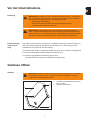
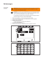
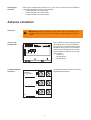
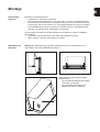
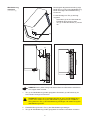

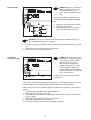


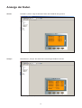

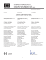


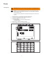
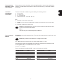
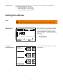
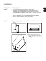
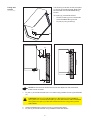
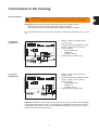
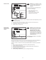
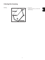
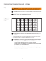
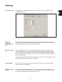


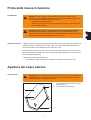
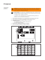


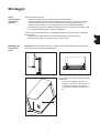


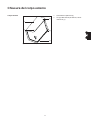
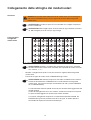
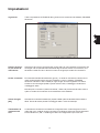
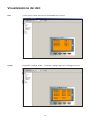


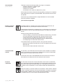
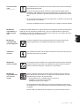


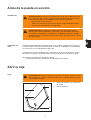


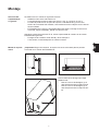
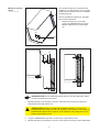
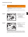
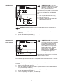
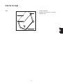

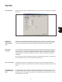


![Fronius String Control 125/25 [42,0410,1268]](http://vs1.manualzilla.com/store/data/006374199_1-8f1f21f20f580b642976bc9720b0b1fe-150x150.png)
![Fronius String Control 125/25 [42,0410,1268]](http://vs1.manualzilla.com/store/data/006734038_1-bda849b151fd277bba46fa211c83e9b1-150x150.png)

![Fronius String Control 250/30 [42,0426,0134,DE]](http://vs1.manualzilla.com/store/data/006734040_1-3ecaad58c89f5ce7d67e32ebe45ca0ef-150x150.png)