1
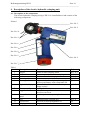
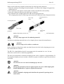
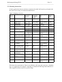
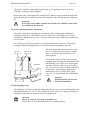
Auf dem Knapp 46 Tel.: ++49(0)2191/907-0 D-42855 Remscheid Fax: ++49(0)2191/907-141 ___________________________________________________________________________ Bedienungsanleitung Instruction Manual EK 22 Inhaltsangabe 1. 2. 3. 4. 4.1. 4.2. 4.3. 4.4. 5. 5.1. 5.2. 5.3. 5.4. 5.5. 5.6. 5.7. 5.8. 6. 7. 8. JCS HE.4077 Einleitung Aufschriften Gewährleistung Beschreibung des elektro-hydraulischen Preßgerätes Beschreibung der Komponenten Beschreibung der Betätigungsfunktionen Beschreibung des Preßvorganges Beschreibung der Leuchtdiodenanzeige Hinweise zum bestimmungsgemäßen Gebrauch Bedienung des Gerätes Erläuterung des Anwendungsbereiches Verarbeitungshinweise Wartungshinweise Ölwechselintervalle Hinweis zur Verwendung des Akkus und des Ladeteils Aufbewahrung und Transport des Preßgerätes Hinweis, welche (Ersatz-) Teile vom Kunden selber ausgewechselt werden dürfen. Verhalten bei Störungen am Preßgerät Außerbetriebnahme/Entsorgung Technische Daten H:\DOKU\BED_KL\HYDR\HE4077.DOC Anzahl der Seiten: 27 Bedienungsanleitung EK 22 Seite 2 ___________________________________________________________________________ Kurzinspektion vor Inbetriebnahme Bitte prüfen Sie als erstes, ob Sie alle im Lieferumfang angeführten Teile erhalten haben. Lieferumfang: 1 1 1 1 elektro-hydraulisches Preßgerät Typ EK 22 Akku (schon im Gerät) Ladegerät Bedienungsanleitung Bitte prüfen Sie anhand Ihres Lieferscheins, ob Sie auch die von Ihnen gewünschten Werkzeugeinsätze und ggf. einen Ersatzakku erhalten haben. Bedienungsanleitung für das elektro-hydraulische Preßgerät Typ EK 22, Seriennummer ............................ 1. Einleitung Vor Inbetriebnahme Ihres Preßgerätes lesen Sie sich die Bedienungsanleitung sorgfältig durch. Benutzen Sie dieses Gerät ausschließlich für den bestimmungsgemäßen Gebrauch. Diese Bedienungsanleitung ist während der gesamten Lebensdauer des Gerätes mitzuführen. Der Betreiber muß - dem Bediener die Betriebsanleitung zugänglich machen und - sich vergewissern, daß der Bediener sie gelesen und verstanden hat. 2. Aufschriften Auf dem an dem Gehäuse angebrachten Typenschild finden Sie Typbezeichnung, Herkunftsangabe und der Firmenname. Auf der gegenüberliegenden Seite des Gehäuses befindet sich ein Aufkleber mit einer Kurzdarstellung der preßbaren Querschnitte für Kupfer und Aluminium, der Preßkraft und der Seriennummer. Am Preßkopf befindet sich ein Hinweis auf eine mögliche Quetschgefahr bei Preßvorgängen. 3. Gewährleistung Die Gewährleistung bei sachgemäßer Bedienung und unter Einhaltung der geforderten regelmäßigen Kontrollen des Gerätes beträgt 6 Monate ab Lieferdatum. Bedienungsanleitung EK 22 Seite 3 ___________________________________________________________________________ 4. Beschreibung des elektro-hydraulischen Preßgerätes 4.1. Beschreibung der Komponenten Das elektro-hydraulische Preßgerät mit unserer Typbezeichnung EK 22 ist ein handgeführtes Gerät und besteht aus folgenden Komponenten: Bild 1 Pos.-Nr. 3 Pos.-Nr. 5 Pos.-Nr. 10 Pos.-Nr. 4 Pos.-Nr. 6 Pos.-Nr. 1 Pos.-Nr. 8 Pos.-Nr. 9 Pos.-Nr. 2 Pos.-Nr. 7 Tabelle 1 Pos.-Nr. Bezeichnung 1 Bedienungsschalter 2 Rückstelltaste 3 4 5 6 7 8 9 10 11 12 Funktion Auslösung des Preßvorgangs Taste zum Öffnen der Preßeinsätze nach der Verpressung Zuganker Vorrichtung zum Öffnen des Preßkopfes Druckknöpfe Preßknopf zum Herausnehmen der Werkzeugeinsätze Gehäusedeckel ergonomisch geformtes Kunststoffgehäuse Leuchtdiodenanzeige Kontrollinstrument zum Feststellen des Ladezustandes und weiterer Gerätefunktionen Akku wiederaufladbarer Akku Verriegelungsschieber Sicherungselement gegen unbeabsichtigte Auslösung eines Preßvorganges Handschutz Bügel zum Schutz der bedienenden Hand Werkzeugeinsätze Preßeinsätze Öltank Vorratsbehälter für das Hydrauliköl Ölstopfen Verschluß für den Ölvorratsbehälter Referenz S 3, 4, 5 S 3, 11 S 3, 5 S 3, 5 S3 S 3, 5, 11 S 3, 10 S 3, 4, 5 S3 S 3, 6 S9 S9 Bedienungsanleitung EK 22 Seite 4 ___________________________________________________________________________ 4.2. Beschreibung der Betätigungsfunktionen Es sollte vor Arbeitsbeginn der Ladezustand des Akkus (Pos.-Nr. 7) überprüft worden sein. Ein niedriger Ladezustand kann beispielsweise an der Leuchtdiode (Pos.-Nr. 6) durch ein 20 s Aufleuchten am Ende einer Pressung erkannt werden. hRückstelltaste to retract ondrücken trigger to Bedienungsschalter drücken p Verriegelungs- hschieber triggerzum lock nAuslösen nach unten schieben Bild 2 Siehe Kap. 4.4 zur Leuchtdiodenanzeige Ein Preßvorgang wird durch die Betätigung des Bedienungsschalters (Pos.-Nr. 1) nach vorheriger Entriegelung des Verriegelungsschiebers (Pos.-Nr. 8) ausgelöst. Das Gerät ist mit einem Nachlaufstop ausgerüstet, der den Vorschub nach Loslassen des Bedienungsschalters sofort stoppt. Durch Drücken der Rückstelltaste fährt der Kolben wieder in seine Ausgangsposition zurück. 4.3. Beschreibung des Preßvorganges Der Preßvorgang wird gekennzeichnet durch das Zusammenfahren der Preßeinsätze. Dabei befindet sich das auf das Kabel aufgeschobene Verbindungsmaterial bei geschlossenem Preßkopf in dem Preßprofil der stationärem Hälfte des Preßeinsatzes. Der auf der Kolbenstange sitzende bewegliche Teil des Preßeinsatzes bewegt sich dabei auf die Preßstelle zu. Der Preßkopf ist stufenlos 360° um die Längsachse drehbar. Dieses ermöglicht Montagen auch an sehr schlecht zugänglichen Stellen. Ein Preßvorgang ist abgeschlossen, wenn die Werkzeugeinsätze zusammengefahren sind. Dieses wird durch ein akustisches Signal, einem Klacken, angezeigt, des durch das Öffnen des Überdruckventils verursacht wird. Sollte das akustische Signal nicht ertönen, ist das Gerät entsprechend Kap. 6 zu überprüfen. Die EK 22 ist mit einer Mikroprozessor-Steuerung ausgestattet, die den Motor nach ertönen des akustischen Signals abschaltet. Durch Drücken der Rückstelltaste (Pos.-Nr. 2) fahren die Werkzeugeinsätze selbständig in die Ausgangsposition zurück. Anschließend kann entweder ein weiterer Preßvorgang vorgenommen werden oder durch Öffnen des Zugankers (Pos.-Nr. 3) das Verbindungsmaterial aus dem Preßkopf herausgenommen werden. 4.4. Beschreibung der Leuchtdiodenanzeige Die Leuchtdiode dient in Verbindung mit der Steuerungselektronik zur Information über den Zustand des Akkus und des Werkzeuges. Im einzelnen leuchtet die Diode in folgenden Fällen: - Beim Einsetzen eines Akkus blinkt die Leuchtdiode einige Male. Damit wird angezeigt, daß die elektronische Steuerung ihren Selbsttest erfolgreich durchführt. - Wenn die Leuchtdiode nach einen Arbeitsvorgang für etwa 20 Sekunden dauernd leuchtet, ist der Akku entladen und muß aufgeladen werden. Bedienungsanleitung EK 22 Seite 5 ___________________________________________________________________________ - Blinkt die Leuchtdiode ab einem bestimmten Zeitpunkt immer am Ende eines Arbeitsvorgangs für etwa 20 Sekunden, dann ist eine Wartung fällig. Das Gerät ist baldmöglichst ins Werk einzuschicken. - Beim Auftreten eines Fehlers blinkt die Leuchtdiode gleichfalls am Ende der Verpressung. Das Blinken zeigt in diesem Fall das Ansprechen der elektronischen Sicherung an. Eine mögliche Ursache dafür ist der Versuch, eine Verpressung mit einem unzulässig entleerten Akku durchzuführen. Tritt das Blinken auch nach Auswechseln des Akkus weiterhin auf, liegt eine andere Störung vor oder eine Wartung ist fällig. In diesen Fällen ist das Gerät ins Werk einzuschicken. - Befindet sich das Gerät in einem Zustand, in dem die Leuchtdiode sowohl dauernd leuchten (Batterie leer) als auch blinken müßte (Wartung fällig) so leuchtet sie zunächst dauernd und blinkt anschließend. 5. Hinweise zum bestimmungsgemäßen Gebrauch 5.1. Bedienung des Gerätes Als erstes wird für die gewünschte Anwendung der geeignete Preßeinsatz bereitgelegt. I Achtung Preßwerkzeug niemals ohne Preßeinsätze betätigen! Anschließend wird der Zuganker (Pos.-Nr. 3) ausgerastet und der Preßkopf geöffnet. Die beiden Hälften der Werkzeugeinsätze werden nacheinander seitlich unter Betätigung der Druckknöpfe (Pos. 4) bis zum Einrasten eingeschoben. Nachdem der Preßkopf wieder vollständig geschlossen wurde, wird der Verriegelungsschieber (Pos.-Nr. 8) für den Bedienungsschalter (Pos.-Nr. 1) freigeschaltet, d.h. nach unten geschoben. Nun wird, wie in Kap. 4.3. beschrieben, der Preßvorgang durchgeführt. Achtung Der Preßvorgang kann jederzeit durch Loslassen des Betätigungsschalters unterbrochen werden. Nach Beendigung des Preßvorganges muß der Verriegelungsschieber (Pos.-Nr. 8) wieder nach oben geschoben werden. Achtung Vor Auswechselung der Werkzeugeinsätze unbedingt Bedienungsschalter mit dem Verriegelungsschieber gegen unbeabsichtigtes Betätigen sichern. Bedienungsanleitung EK 22 Seite 6 ___________________________________________________________________________ 5.2. Erläuterung des Anwendungsbereiches Unser elektro-hydraulisches Preßgerät vom Typ EK 22 verfügt über eine große Anzahl verschiedener Werkzeugeinsätze (Pos.-Nr. 10) zum Verpressen von Cu- und Al-Verbindungsmaterial. Tabelle 2 Bild 3 Preßbereich ________________________________________________________________________ a 6-300 mm² Rohrkabelschuhe und Verbinder „Normalausführung“ _____________________________________________________________________ b 6-240 mm² Preßkabelschuhe und Verbinder DIN 46235/DIN 46267 ________________________________________________________________________ c 10-240 mm² Aluminium Kabelschuhe und Verbinder _____________________________________________________________________ d 25-185 mm² Preßverbinder für zugfeste Verbindungen von Aldrey-Seilen nach DIN 48201, Blatt 6 und Al-Leiter DIN 48201, Blatt 5, 120 - 185 mm² _____________________________________________________________________ e 25/4-120/20 mm² Preßverbinder DIN 48085 Teil 3 für AL-/St-Seile DIN 48204 ________________________________________________________________________ f 10-240 sm mm² Runddrückeinsätze für für Al- und Cu-Sektorleiter 35-300 se mm² ________________________________________________________________________ g 10-70 mm² Quetschkabelschuhe DIN 46234, Stiftkabelschuhe DIN 46230 _____________________________________________________________________ h 10-70 mm² Isolierte Quetschkabelschuhe ________________________________________________________________________ i 10-70 mm² Rohrkabelschuhe für feindrähtige Leiter ________________________________________________________________________ j 4-50 mm² C-Abzweigklemmen ________________________________________________________________________ k 10-150 mm² isolierte Rohrkabelschuhe und Verbinder sowie isolierte Stiftkabelschuhe ________________________________________________________________________ l 2x50-2x70 mm² Doppel-Preßkabelschuhe ________________________________________________________________________ m 10-50 mm² Nickel-Kabelschuhe und Verbinder ________________________________________________________________________ n 10-70 mm² Ovale Preßverbinder DIN 48217 Al + Cu und Preßendbunde ________________________________________________________________________ o 10-185 mm² Aderendhülsen ________________________________________________________________________ p 2x4-2x16 mm² Zwillingsaderendhülsen Bitte beachten Sie unbedingt die im Katalog Kapitel 12 angeführten Montagehinweise. Bedienungsanleitung EK 22 Seite 7 ___________________________________________________________________________ Achtung Es dürfen nur die in Tab. 2 genannten Verbindungsmaterialien verpreßt werden. Sollten andere Verbindungsmaterialien verpreßt werden müssen, ist eine Rücksprache mit dem Werk zwingend erforderlich. Achtung Desweiteren dürfen keine unter Spannung stehenden Teile verpreßt werden. Vor Arbeitsbeginn ist ein spannungsfreier Zustand der zu verpressenden Verbindung sicherzustellen. Bei dem EK 22 handelt es sich um ein handgeführtes Gerät das nicht eingespannt werden darf. Es darf nicht für den stationären Einsatz verwendet werden. Das Gerät ist nicht für den Dauerbetrieb geeignet. Es muß nach ca. 30-40 Verpressungen hintereinander eine kurze Pause von mindestens einer viertel Stunde eingelegt werden, damit dem Gerät Zeit zur Abkühlung gegeben wird. I Achtung Bei zu intensivem Gebrauch kann es durch Erhitzung zu Schäden am Gerät kommen. Achtung Beim Betrieb von Elektromotoren kann es zur Funkenbildung kommen, durch die feuergefährliche oder explosive Stoffe in Brand gesetzt werden können. Achtung Das Elektrohydraulische Preßgerät darf nicht bei starkem Regen oder unter Wasser eingesetzt werden. Bedienungsanleitung EK 22 Seite 8 ___________________________________________________________________________ 5.3. Verarbeitungshinweise Bei weiteren über die in Tabelle 2&3 angeführten Anwendungsfällen hinaus ist zwingend Rücksprache mit dem Werk zu halten. Tabelle 3 Kennzeichnung der Werkzeugeinsätze Zuordn. Preßeinsätze Kennzeichnung Kennzeichnung Oberfläche des Tab. 2 außen Preßprofil Preßeinsatzes a Normalausführung CU, QS QS gelb chromatisiert b DIN 46235/ CU, QS, Kennzahl gelb DIN 46267 DIN 46235 chromatisiert c Aluminium AL, QS Kennzahl blau verzinkt d Al-Preßverbinder Al, QS Kennzahl blau verzinkt Aldrey e Preßverbinder Al, QS Kennzahl blau verzinkt DIN 48085 T3 St, QS Kennzahl brüniert f Runddruckeinsatz RU; QS, sm; gelb QS, sm chromatisiert g Quetsch-/Stift-KS CU, QS, QS gelb DIN 46234 chromatisiert h isol. Quetsch-KS ISQ, QS QS gelb chromatisiert i Rohr-KS für F, QS QS gelb feindrähtige Leiter chromatisiert j C-Abzweigkl. C, QS gelb chromatisiert k Rohr-KS und VB IS, QS QS gelb isol., Stift-KS isol. chromatisiert l Doppel-Preß-KS DP, QS QS gelb chromatisiert m Nickel-KS + VB Ni, QS blau verzinkt n Ovale Preß-VB Cu o. Al, QS QS gelb cromatisiert o AEH DIN 46228 AE, QS gelb chromatisiert p Twin AEH AE, 2xQS gelb chromatisiert Preßbreite 5 mm 5 mm 7 mm 7 mm 7 mm 5 mm 5 mm 5 mm 5 mm 5 mm - Abküzungen: KS-Kabelschuhe, AEH-Aderendhülsen, QS-Querschnitt Mit den in Tabelle 3 Abs. a aufgeführten Einsätzen dürfen ausschließlich Klauke Rohrkabelschuhe und Verbinder in Normalausführung verarbeitet werden. Eine Verpressung von handelsüblichen Kabelschuhen und Verbindern anderer Hersteller ergibt keine ordnungsgemäße Verpressung. Bedienungsanleitung EK 22 Seite 9 ___________________________________________________________________________ Mit den in Tabelle 3 Abs. j beschriebenen Einsätzen für C-Klemmen dürfen ausschließlich Klauke Klemmen verpreßt werden. Bei C-Klemmen anderer Hersteller kann keine Garantie für eine ordnungsgemäße Verpressung gegeben werden. Trotz gleicher Kennzahl sind die Preßbreiten bei Cu- und Al-Preßkabelschuhen und Verbindern unterschiedlich. Zur Kennzeichnung sind die Einsätze neben der Aufschrift noch farblich unterschiedlich ausgeführt. Achtung Es dürfen auch bei gleicher Kennzahl nur die für das Material vorgesehenen Werkzeugeinsätze verwendet werden. I 5.4. Wartungshinweise Das elektro-hydraulische Preßgerät ist nach jedem Gebrauch zu reinigen und ein trockener Zustand vor Einlagerung sicherzustellen. Sowohl Akku als auch Ladegerät müssen vor Feuchtigkeit und vor Fremdkörpern geschützt werden. Das Gerät ist im Prinzip wartungsfrei, lediglich der Ölstand ist regelmäßig zu kontrollieren und die Bolzenverbindungen leicht einzuölen. Ölstopfen Pos.-Nr. 12 Öltank Pos.-Nr. 11 Bild 4 Zur Ölstandskontrolle das Gerät mit dem Preßkopf nach unten halten, den Gehäusedeckel (Teile-Nr. 5) demontieren, den darunterliegenden Ölstopfen (Pos.-Nr. 12) entfernen und durch die Öffnung den Ölstand kontrollieren, bzw. den Öltank (Pos.-Nr. 11) bis zum Rand füllen. Nach erfolgter Wartung den Ölstopfen wieder einsetzen und den Gehäusedeckel aufschrauben. Folgende legierte Hydrauliköle der Viskositätsklasse VG 15 und der Qualitätsstufe HPL können bei Umgebungstemperaturen von -20°C bis +40°C verwendet werden: AVIA HVI 15, Shell Tellus T 15, Mobil DTE 11, NUTO H 15, Rando HD - Z15, Agip OSO 15, BP Energol HLP 15 Achtung Verschüttetes Hydrauliköl muß sofort mit Saugmaterial gebunden werden. Bedienungsanleitung EK 22 Seite 10 ___________________________________________________________________________ 5.5. Ölwechselintervalle Das Hydrauliköl wird im Rahmen der durch die Leuchtdiodenanzeige angezeigten fälligen Wartung werkseitig gewechselt. Sollte dennoch ein Ölwechsel notwendig sein, so müssen legierte Hydrauliköle mit obiger Spezifikation verwendet werden. I Achtung Bitte verwenden Sie nur sauberes, einwandfreies Hydrauliköl Achtung Hydrauliköle können Hautausschläge und andere Gesundheits-schädigungen hervorrufen. Vermeiden Sie längeren Hautkontakt. Waschen Sie sich nach jedem Kontakt gründlich. 5.6. Hinweis zur Verwendung des Akkus und des Ladeteils Das Ladegerät ist für Wechselspannung von 230 V mit einer Frequenz von 50 Hz ausgerüstet. Neue Akkus müssen vor dem erstmaligen Gebrauch geladen werden. Zur Aufladung des Akkus wird der Stecker des Ladegerätes in die Steckdose und der Akku in das Ladegerät eingesteckt. Die Ladezeit beträgt ca. eine Stunde. Der Ladezustand des Akkus kann an einer Leuchtdiode am Ladegerät abgelesen werden. grün: rot: blinken: Akku ist aufgeladen Akku ist leer und wird gerade geladen. Akku falsch eingeschoben oder Akku zu heiß, ein akustisches Signal ertönt. Schieben Sie den Akku so in das Gerät, daß die Plus- und Minuspole an der Batterie denen am Lader entsprechen. Ist der Akku richtig angeschlossen, so wechselt das Ladelicht von grün auf rot und der Ladevorgang beginnt. Ist der Ladevorgang abgeschlossen wechselt das Ladelicht wieder auf grün, wobei gleichzeitig ein Piepton 5 Sekunden lang abgegeben wird. Es dürfen keine artfremden Akkus z.B. Trockenbatterien oder Autobatterien etc. weder in der Presse noch im Ladegerät verwendet werden. Laden Sie Ihren Akku auf, sobald die Geschwindigkeit Ihrer Maschine merklich nachläßt. Laden Sie nicht vorsichtshalber einen teilentladenen Akku nach. Wenn Sie einen Akku aus einem kürzlich betriebenen Gerät oder einen, der längere Zeit in der Sonne lag, laden, kann das Aufladelicht rot blinken. Warten Sie in diesem Fall eine Weile. Das Aufladen beginnt nach Abkühlung des Akku. Blinkt das Aufladelicht abwechselnd rot und grün und wird ein Piepton 20 sec. lang abgegeben, ist das Aufladen nicht möglich. Die Pole des Ladegerätes oder die des Akkus sind durch Staub verschmutzt oder der Akku ist verbraucht oder beschädigt. Wollen Sie zwei Akkus hintereinander aufladen, warten Sie 15 min bevor Sie den zweiten Akku laden. Bedienungsanleitung EK 22 Seite 11 ___________________________________________________________________________ Vermeiden Sie starke Temperaturschwankungen unter 0°C und über 40°C. Dadurch können Beschädigungen sowohl am Akku als auch an der Presse auftreten. Die optimale Betriebstemperatur liegt zwischen 15 und 25 °C. Lassen Sie das Ladegerät nie im Regen oder Schnee liegen. Laden Sie den Akku nicht in Anwesenheit leicht entzündbarer Stoffe oder Gase. Tragen Sie das Ladegerät nie am Netzkabel und ziehen Sie es nicht gewaltsam aus der Steckdose heraus. Stecken Sie keine fremden Gegenstände in die Lüftungsgitter des Ladegerätes. Das Laden der Akkus darf nur in den vom Hersteller vorgeschriebenen Ladegeräten vorgenommen werden. Achtung Stecken Sie den Akku nicht in Ihre Hosentasche oder in Ihre Werkzeugkiste wenn sich in ihnen leitfähige Teile befinden, wie z.B. Münzen, Schlüssel, Werkzeuge oder andere metallische Teile. Ziehen Sie den Stecker des Ladegerätes nach dem Laden aus der Steckdose heraus. Nehmen Sie das Ladegerät nicht auseinander. Um die Sicherheit und Zuverlässigkeit des Ladegerätes zu gewährleisten sollten Reparatur, Wartung oder Einstellung durch unser Service-Center durchgeführt werden. 5.7. Aufbewahrung und Transport des Preßgerätes Um das Preßgerät vor Beschädigungen zu schützen, muß das Preßgerät nach Gebrauch und nachdem es gesäubert worden ist, in den Transportkoffer gelegt werden, der dann anschließend sicher zu verschließen ist. In diesem Koffer finden desweiteren ein Ersatzakku, das Ladegerät, 10 Werkzeugeinsätze und die Betriebsanleitung platz. 5.8. Hinweis welche (Ersatz-) Teile vom Kunden selber ausgetauscht werden dürfen. Im Rahmen des bestimmungsgemäßen Gebrauchs dürfen vom Kunden nur das Öl und die Werkzeugeinsätze gewechselt werden. I Achtung Geräteversiegelung nicht beschädigen! Bei Beschädigung der Geräteversiegelung erlischt der Garantieanspruch. Die Geräteversiegelung besteht aus einer Schraubenfarbversiegelung und aus einem unlösbaren Siegelaufkleber, der sich unterhalb des Öltanks befindet. Bedienungsanleitung EK 22 Seite 12 ___________________________________________________________________________ 6. Verhalten bei Störungen am Preßgerät a.) Die Preßeinsätze bleiben während des Preßvorganges stehen. => Ölstand kontrollieren. Sollte der Fehler dadurch nicht beseitigt werden können, muß das Gerät ins Werk eingeschickt werden. b.) Regelmäßiges Leuchten der Leuchtdiodenanzeige => Akku austauschen. Leuchtet die Anzeige weiter, muß das Gerät eingeschickt werden. (siehe auch Kap. 4.4) c.) Das Preßwerkzeug verliert Öl. => Das Gerät einschicken. Das Gerät nicht öffnen und die Geräteversiegelung entfernen. d.) Preßwerkzeug löst bei Enddruck nicht aus. => Preßvorgang unterbrechen. Rückstelltaste (Pos.-Nr. 2) gedrückt halten und gleichzeitig Bedienungsschalter ca. 10 sec. dauerbetätigen. Wird der Fehler dadurch nicht behoben, muß das Gerät ins Werk eingeschickt werden. 7. Außerbetriebnahme/Entsorgung Auch bei qualitativ hochwertigen Geräten ist irgendwann der Zeitpunkt gekommen, an dem die Entsorgungsfrage gestellt werden muß. Die Entsorgung der einzelnen Komponenten des Aggregates muß getrennt erfolgen. Dabei muß zuerst das Öl abgelassen werden und an speziellen Abnahmestellen entsorgt werden. Achtung Hydrauliköle stellen eine Gefahr für das Grundwasser dar. Unkontrolliertes Ablassen oder unsachgemäße Entsorgung steht unter Strafe. (Umwelthaftungsgesetz) Als nächstes muß der Akku speziell entsorgt werden. Bei der Entsorgung der restlichen Teile des Aggregates sind die jeweiligen Umweltstandards zu berücksichtigen. Wir empfehlen wegen möglicher Umweltverschmutzung die Entsorgung durch zugelassene Fachunternehmen vornehmen zu lassen. Eine kostenfreie Rücknahme des Altgerätes durch den Hersteller kann nicht zugesagt werden. Bedienungsanleitung EK 22 Seite 13 ___________________________________________________________________________ 8. Technische Daten Gewicht des kompl. Gerätes: Preßkraft: Antriebsmotor: Motorspannung: Ladespannung: Akku-Ladezeit: Preßzeit: Schließgeschwindigkeit: Preßleistung: Hydrauliköl: Schalldruckpegel: Vibrationen: ca. 3,2 kg ca. 55 kN Gleichstrom-Permanentfeldmotor 12 V DC 12 V ca. 1 h ca. 7 s 2,4 mm/s ca. 120 Pressungen/Akku ca. 65 ml "AVIA HVI 15" 75 dB (A) in 1m Abstand < 2,5 m/s² (gewichteter Effektivwert der Beschleunigung) Maße: Kolbenhub: Öffnungsbreite des Preßkopfes: Außendurchmesser des Kopfes: Länge des Kopfes: Länge des Gehäuses: Gesamthöhe: Länge Kopf und Gehäuse: I 15 mm 42,4 mm 90,5 mm 130 mm 185 mm 280 mm 315 mm Hinweis Wenn Sie einmal Unterstützung bezüglich dieses Gerätes benötigen, so rufen Sie bitte unser SERVICE-CENTER an. Tel.: 02191/907-222 Fax: 02191/907-243 Symbole Sicherheitstechnische Hinweise Bitte unbedingt beachten, um Personenund Umweltschäden zu vermeiden. I Anwendungstechnische Hinweise Bitte unbedingt beachten, um Schäden am Gerät zu vermeiden. Anmerkung Diese Bedienungsanleitung jederzeit kostenlos unter der Bestell-Nr. HE.4077 nachbestellt werden. Version 2.d 7/97 Auf dem Knapp 46 Tel.: 02191/907-0 D-42855 Remscheid Fax: 02191/907-141 ___________________________________________________________________________ Instruction Manual EK 22 Index 1. 2. 3. 4. 4.1. 4.2. 4.3. 4.4. 5. 5.1. 5.2. 5.3. 5.4. 5.5. 5.6. 5.7. 5.8. 6. 7. 8. JCS HE.4077 Introduction Labels Warranty Description of the electric-hydraulic crimping unit Description of the components Description of the operation functions Description of the crimping processes Description of the light diode display Remarks in respect of the determined use Operation of the units Explanation of the application range Mounting instructions Service and maintenance instructions Oil changing cycles Remarks on the use of the battery cartridge and charger Storage and transport of the crimping unit. Reference as to which (spare-) parts can be exchanged by the customer. Troubleshooting Putting out of operation/waste disposal Technical data H:\DOKU\BED_KL\HYDR\HE4077.DOC Anzahl der Seiten: 27 Bedienungsanleitung EK 22 Seite 15 ___________________________________________________________________________ Brief inspection before putting into service Please check immediately if you received all parts mentioned in our basic supply. Basic supply: 1 1 1 1 Electric-hydraulic crimping unit Type EK 22 Battery cartridge (plugged in the unit) Charging unit Instruction manual Please check according your bill of delivery if you received all requested dies and e.g. a spare battery cartridge. Instruction Manual for the electric-hydraulic crimping unit Type EK 22, Serial-No. ............................ 1. Introduction Before starting to use the tool please read the instruction manual carefully. Use this tool exclusively for its determined use. Mounting and assembly of connecting material with the help of this tool must only be performed by specially trained personnel. The minimum age is 16 years. This instruction manual has to be carried along during the entire life span of that tool. The operator has - to guaranty the availability of the instruction manual for the user and - to make sure, that the user has read and understood the instruction manual. 2. Labels On the labels fixed on the housing of the tool you’ll find the type specification name of the manufacturer and the company logo. On the opposite side of the housing you’ll find a label with a brief presentation of the scope of manageable cross-sections for copper and aluminium, the pressing force and the serial number. On the crimping head you’ll find a warning against possible injuries during the crimping process. 3. Warranty If correct operation is guaranteed and regular service is provided our warranty is 6 months from the time of delivery. Bedienungsanleitung EK 22 Seite 16 ___________________________________________________________________________ 4. Description of the electric-hydraulic crimping unit 4.1. Description of the components The electric-hydraulic crimping unit type EK 22 is a hand held tool and consists of the following components: Picture 1 Pos.-No. 3 Pos.-No. 5 Pos.-No. 10 Pos.-No. 4 Pos.-No. 6 Pos.-No. 1 Pos.-No. 8 Pos.-No. 9 Pos.-No. 2 Pos.-No. 7 Table 1 Pos.-No. 1 2 3 4 5 Description Trigger Retract button latch Retaining clips Housing 6 Light diode display 7 8 Battery cartridge trigger lock 9 Removable hand guard Dies Oil reservoir Oil plug 10 11 12 Function switch to start crimping action button to open the dies after crimping device to close the crimping head button to remove the dies ergonomically formed plastic housing for perfect performance with a detachable lid indicator for tool functions and battery charge control rechargeable battery safety lock to guarantee that no unintentional processes can occur. guard to protect the operating hand Reference pp 3, 4, 5 pp 3, 11 pp 3, 5 pp 3, 5 p3 p3 interchangeable crimping dies reservoir to store the hydraulic oil plug to close the oil tank pp 3, 6 p9 p9 pp 3, 5, 11 pp 3, 10 pp 3, 4, 5 Bedienungsanleitung EK 22 Seite 17 ___________________________________________________________________________ 4.2. Description of the operation- and control functions Push to retract piston Pull trigger to crimp Push trigger lock down A crimping process will be initiated by pressing the trigger (Pos.-No. 1) after having released the trigger lock (Pos.-No. 8). The unit is supplied with a special brake which stops the forward motion of the piston after having released the trigger. Push retract button to return the piston into starting position. picture 2 Please see chapter 4.4 for more information on the light diode display. 4.3. Description of the crimping processes The crimping process is defined by the closing motion of the dies. During that process the connecting material is positioned in the stationary half of the die whereas the moving part of the die is approaching the compression point. The crimping head can be smoothly turned by 360° around the longitudinal axis in order to gain better access to tight corners and other difficult working areas. The crimping process is terminated when the dies contact each other. This is indicated by an acoustic signal, a „pop“, which signals that the high pressure valve has opened and that the maximum operating pressure has been reached. If that signal should not occur the unit must be checked according to chapter 6. The EK 22 is equipped with a microprocessor which shuts off the motor automatically after the acoustic signal occurred. After pressing the retract button the dies return to the starting position. Afterwards a second crimping cycle can be initiated or the crimping process can be terminated by opening the latch (Pos.-No.3) 4.4. Description of the light diode display This tool is equipped with a electronic controller with several important features to inform the user about the current status of the unit. These diode signals in the following cases: - The diode will signal periodically a few times while the battery is being inserted into the tool. This indicates that the electronic circuitboard performed its self-test successfully. If the diode signals continuously after a crimping cycle for approx. 20 sec. the battery is discharged and must be recharged again. Does the diode signal periodically at the end of a crimping cycle for approx. 20 sec the unit must be returned to an authorised Service Center for Service as soon as possible. Bedienungsanleitung EK 22 Seite 18 ___________________________________________________________________________ - - In case of an error the light diode display also signals periodically at the end of an pressing cycle. The signal indicates in this case the circuit opening by the electronic fuse. A possible reason for that is that a pressing cycle was performed with an incorrectly low battery. If the signal occurs even after changing the battery there must be a different error or a service is due. In these cases the tool must be returned to the manufacturer or an authorised service center. Is the unit in a state in which the diode should signal continuously (Battery empty) as well as periodically (Service due) the diode signals first continuously and then periodically. 5. Remarks in respect of the determined use 5.1. Operation of the units First you have to select the right dies for the intended application. Attention Don’t use the tool without dies. The crimping head has to be opened by unhooking the latch (Pos.-No. 3). Afterwards the retaining clips (Pos.-No. 4) have to be pressed while the dies will be inserted into the opened crimping head. After having completely closed the crimping head the trigger lock (Pos.-No. 8) for the trigger (Pos.-No. 1) will be released, which means that it is pushed down. The crimping process will proceed as described in chapter 4.3. Please see also chapter 4.4. for further information on the diode functions. Attention The crimping process can be interrupted at any moment by releasing the trigger. After the crimping process has been finished the trigger lock (Pos.-No. 8) has to be pushed up again. Attention Before changing the dies the trigger has to be locked with the trigger lock to avoid unintended use. Bedienungsanleitung EK 22 Seite 19 ___________________________________________________________________________ 5.2. Explanation of the application range Our electric-hydraulic crimping tool type EK 22 has a large number of various dies (Pos.-No. 10) available to crimp copper and aluminium connecting material. Table 2 Picture 3 Crimping range Connecting material ___________________________________________________________________________ a 6-300 mm² Tubular cable lugs and connectors „Standard type“ _____________________________________________________________________ b 6-240 mm² Compression cable lugs and joints DIN 46235/DIN 46267 ___________________________________________________________________________ c 10-240 mm² Aluminium cable lugs and connectors ___________________________________________________________________________ d 25-185 mm² Compression joints for full-tension connections for Aldrey conductors acc. to DIN 48201, sheet 6 and Al-conductors acc. to DIN 48201, sheet 5, 120-185 mm² ___________________________________________________________________________ e 25-4 to mm² Compression joints acc. to DIN 48085, part 3 for 120-20 AL/steel conductors acc. to DIN 48204. ___________________________________________________________________________ f 10-185 sm mm² Pre-rounding dies for Al- and Cu-sector-conductors 35-240 se mm² ___________________________________________________________________________ g 10-70 mm² Solderless Terminals DIN 46234, Pin terminals DIN 46230 _____________________________________________________________________ h 10-70 mm² Insulated solderless terminals ___________________________________________________________________________ i 10-70 mm² Tubular cable lugs for fine-stranded conductors ___________________________________________________________________________ j 4-50 mm² C-clamps ___________________________________________________________________________ k 10-150 mm² Pre-insulated tubular cable lugs and connectors, insulated pin cable lugs ___________________________________________________________________________ l 2x50 to mm² Double compression cable-lugs 2x70 ___________________________________________________________________________ m 10-50 mm² Tubular nickel cable lugs ___________________________________________________________________________ n 10-70 mm² oval shape compression joints acc. to DIN 48217 and compression dead ends ___________________________________________________________________________ o 10-95 mm² Cable end-sleeves ___________________________________________________________________________ p 2x4-2x16 mm² Twin cable end-sleeves Bedienungsanleitung EK 22 Seite 20 ___________________________________________________________________________ Please use the following assembly instructions for cable lugs and connectors: 1. Strip the conductor according to insertion depth (+10% due to the change of length of the crimped sleeve) 2. The Conductor ends must be cleaned with a cloth or brush before the assembly. 3. Insert the conductor fully into the cable lug or connector 4. Pay attention to the crimping directions and use the appropriate dies. The crimping directions for cable lugs and connectors is indicated in the illustration below. First crimp Side a Crimping direction Side b Crimping direction First crimp picture 3 Crimping direction Side a First crimp Side b 5. After crimping, wipe away excess compound forced out of Al-cable lugs and connectors. Attention Do only crimp copper and Al conducting material If different conducting materials have to be crimped, please contact the manufacturer. Attention Do not crimp on live cables or conductors Before starting to crimp please make sure that all parts involved in the crimping process are not connected to live circuits. The EK 22 is a hand held tool and it is not supposed to be restrained in a vise. It is not allowed to use the tool in a stationary application. The tool is not designed for continued crimping action. After a sequence of approximately 3040 completed crimps you have to make a break of a quarter of an hour to give the tool time to cool down. Attention Too intensive use can cause heat damages for the tool Attention During the operation of electric engines sparks can occur which might ignite highly inflammable or explosive liquids and materials Attention Electric-hydraulic crimping tools should not be operated in pouring rain or under water. Bedienungsanleitung EK 22 Seite 21 ___________________________________________________________________________ 5.3. Mounting instructions If other applications that exceeds those mentioned in table 2&3 must be performed with this tool it is necessary to contact the manufacturer. Table 3 Marking of the dies Relation Dies Tab. 2 Marking outside a „Standard type“ CU, „QS“ b DIN 46235/ DIN 46267 Aluminium compression joint Aldrey Compression joint DIN 48085 part 3 Pre-rounding dies CU, „QS“, DIN 46235 AL, „QS“ Al, „QS“ c d e f g h i j k Al, „QS“ ST, „QS“ RU; QS, sm; QS, sm Terminals CU, „QS“, DIN 46234/46230 DIN 46234 insulated terminals ISQ, QS tub. CL for finestr. conductors C-clamps F, QS C, QS IS, QS o pre-insulated tub. CL and connectors double compression CL Ni-CL and connectors Oval compression joints AEH DIN 46228 p Twin AEH AE, 2xQS l m n DP, QS NI, QS CU or AL, QS AE, QS Marking crimping profile „QS“ Surface of the dies Crimping width chrome plated, yellow code number chrome plated, yellow code number blue zinc code number blue zinc 5 mm code number blue zinc code number black chrome plated, yellow QS chrome plated, yellow QS chrome plated, yellow QS chrome plated, yellow chrome plated, yellow QS chrome plated, yellow QS chrome plated, yellow blue zinc 7 mm 5 mm - code number chrome plated, yellow chrome plated, yellow chrome plated, yellow - 5 mm 7 mm 7 mm - - Abbreviations: CL-tubular cable lugs, AEH-cable end-sleeves, QS-Cross-section With those dies mentioned in Table 3a only Klauke cable lugs and connectors „Standard type“ are supposed to be crimped. Crimping of commercial cable lugs and connectors of other suppliers will not result in a perfect crimp. Bedienungsanleitung EK 22 Seite 22 ___________________________________________________________________________ The same is valid for conducting material table 3g. No guarantee can be given for crimping C-clamps of other suppliers. Despite the same code numbers the compression width for copper and aluminium cable lugs and connectors is different. Besides the marking of the dies the plating is different too. Attention Even if the code number is identical only those dies should be used which are suitable for the material. 5.4. Service and maintenance instruction The electric-hydraulic crimping unit is equipped with a sophisticated switchboard enabling the user to see when the next service is due. (Pls. read chapter 4.4 for more information) When the next service is due the unit needs to be returned to an authorised service center. For every day service the unit has to be cleaned and dried after each use. The battery cartridge and the charging unit have to be protected against humidity and dust. Oil-plug Pos.-No. 12 The unit is basically maintenance-free, only the oil level has to be checked on a regular basis as well as the bolt joints have to be oiled regularly. Oilreservoir Pos.-No. 11 picture 4 To check the oil level of the unit, point the crimping head to the ground and dismount the tank housing cover, remove the oil plug and check the oil level. If the oil reservoir (Pos.No. 11) proves to be not completely full fill it up to the top. After having completed the maintenance service push in the oil plug (Pos.-No. 12) and assemble the tank housing cover. Attention Spilled hydraulic oil has to be absorbed immediately. 5.5. Oil changing cycles The hydraulic oil will be completely changed during the service intervals indicated by the light diode display (Pos.-No. 6). We recommend to have the service done in specialised companies where the safe disposal of the oil is guaranteed. Attention Please do only use clean, proper hydraulic oil. (AVIA HVI 15 and other Hydraulic oils of similar quality) Bedienungsanleitung EK 22 Seite 23 ___________________________________________________________________________ Attention Hydraulic oils can cause cutaneous eruption (eczema) or other health hazards. Avoid longer skin contacts. Wash your hands carefully after each contact. The following hydraulic oils with the viscosity class VG 15 and the quality level HLP are suitable within the temperature range of –20 to +40°C: AVIA HVI 15, Shell Tellus T 15, Mobil DTE 11, NUTO H 15, Rando HD - Z15, Agip OSO 15, BP Energol HLP 15. 5.6. Remarks on the use of the battery cartridge and charging unit. The charging unit is run with a nominal voltage of 230 V and a frequency of 50 Hz. New Batteries must be charged prior to use. To charge the battery cartridge (Pos.-No. 7) the power plug of the charging unit has to be plugged into the power supply and the battery cartridge has to be pushed into the charging unit. The charging time is one hour. The charging level of the battery cartridge can be checked by a LED. green red flashing battery cartridge is charged Battery cartridge is empty and is just being charged battery cartridge is not pushed in properly or too hot, a sound signal occurs Push the battery into the charging unit so that the polarity of the poles of the battery corresponds to those at the charger. Is the battery plugged in correctly the LED changes from green to red and the charging procedure starts. When the charging procedure is terminated the LED changes again to green. Simultaneously a signal occurs for 5 seconds. No other battery cartridges e.g. dry batteries or car batteries etc. are permitted to be used neither in the tool nor in the charging unit. As soon as the speed of the machine decreases noticeably the battery must be recharged. Do not recharge a partially empty battery as a precaution. If charging a battery which has currently been used or which was laying in the sun for a longer period of time the LED might flash red. In this case wait for a while. The charging procedure starts after the battery cooled down. Does the LED flash red and green and does an audible tone occur for 20 seconds it is not possible to charge that battery. The poles of the battery or the charging unit are dirty or the battery is low or damaged. If you want to charge two batteries in a row wait for 15 min before you charge the second battery. Avoid great fluctuating temperatures under 0°C and above 40°C. Through these fluctuations damages may result for the battery cartridge as well as for the charging unit. The best operation temperature is between 15-25 °C. Bedienungsanleitung EK 22 Seite 24 ___________________________________________________________________________ Do not leave or operate the charging unit in rain or snow. Do not charge the battery near lightly inflammable materials or gases. Do not use the cord to transport the charging unit or to pull the plug out of the mains socket with force. Do not insert strange parts into the ducts of the charging unit. Attention Do not place the battery in your pocket or in your toolbox if there are any conductive materials in it such as coins, keys, tools or other metallic parts. The charging of the batteries must only be done with charging units supplied by the manufacturer. Pull the plug of the charging unit after charging. Do not disassemble the charging unit or battery. In order to safeguard a safe and proper performance of the charging unit the repair and service of the unit should be made through our Service Center. 5.7. Storage and transport of the crimping tool In order to protect the tool against damages it has to be cleaned carefully after every use and be put into the transportation case which has to be closed safely. Into this case you can put a spare battery cartridge, the charging unit, 16 dies and the instruction manual. 5.8. Reference as to which spare parts can be exchanged by the customers Within the determined use of the tool only the dies (Pos.-No. 10) and the oil are permitted to be changed by the customers. Attention Do not damage the seals of the tool. If the seals are damaged the warranty is invalidated. The seals of the tool consists of colour coating of the screw heads and of a permanent decal under the oil reservoir. Bedienungsanleitung EK 22 Seite 25 ___________________________________________________________________________ 6. Troubleshooting a.) The dies (Pos.-No. 10) came to a standstill during the crimping operation. => Check oil level. If the malfunction can’t be eliminated the tool has to be returned to the manufacturer. b.) Flashing of the light diode display (Pos.-No. 5) => See chapter 4.4 for more information about the special functions of the tool. c.) The tool loses oil. => Return the tool to the manufacturer. Do not open the tool and damage the seal of the tool. d.) The crimping tool doesn’t reach the final operating pressure. => Stop the crimping process. Press the retract button (Pos.-No. 2) and the operating switch continuously and simultaneously for about 10 sec. Is the malfunction not be eliminated by this attempt the tool has to be returned to the manufacturer. 7. Putting out of operation/waste disposal After intensive use even a high-quality tool has to be put of operation. The disposal of the various components of the tool have to be treated separately. Doing that the first step is to dispose of the oil at special delivery points. Attention Hydraulic oils represent a danger for the ground-water. Uncontrolled draining of or improper disposal is under penalty. (environmental liability law) Next, the battery cartridge has to be specially disposed of. To dispose of the remaining parts of the unit please consult your national environmental laws. Because of possible environmental damages we recommend to dispose of the tool by professional companies. A return of the old tool free of charge to the manufacturer cannot be granted. Bedienungsanleitung EK 22 Seite 26 ___________________________________________________________________________ 8. Technical Data Weight of the complete tool: Crimping force: Driving motor: Motor voltage: Charging voltage: Charging time: Crimping time: Closing speed: Crimping performance: Hydraulic oil: Sound level: Vibrations: ca. 3,2 kg ca. 55 kN direct-current permanent field motor 12 V DC 12 V ca. 1 h ca. 7 s 2,4 mm/s ca. 120 compressions/battery ca. 65 ml "AVIA HVI 15" 75 dB (A) in 1m distance < 2,5 m/s² Dimensions: Piston stroke: Width of the crimping head: Length of the crimping head: Length of the housing: Complete height: Length head and housing: 15 mm 80 mm 130 mm 165 mm 280 mm 300 mm Remark If you should need support in respect of this tool please contact our Service Center. Tel.: Fax: ++ 49 (0)2191/907-222 ++ 49 (0)2191/907-243 Symbols Safety warnings Please do not disregard these instructions in order to avoid human injuries and environmental damages. Operational warnings Please do not disregard them to avoid damaging the pump unit. Version 2.d 7/97 Auf dem Knapp 46 D-42855 Remscheid ___________________________________________________________________________ Handgeführte Elektrowerkzeuge Typ EK 22 (D) CE - Konformitätserklärung. Wir erklären in alleiniger Verantwortlichkeit, daß dieses Produkt mit den folgenden Normen oder normativen Dokumenten übereinstimmt: DIN EN 292 Teil 1 und 2, EN 294, EN 349, EN 60204-1, EN 28662-1, EN 50081-1, EN 50082-2, EN 60529 gemäß den Bestimmungen der Richtlinien 89/392/EWG, 89/336/EWG (GB) CE - Declaration of conformity. We declare under our sole responsibility that this product is in conformity with the following standards or normative documents: DIN EN 292 Teil 1 und 2, EN 294, EN 349, EN 60204-1, EN 28662-1, EN 50081-1, EN 50082-2, EN 60529 in accordance with the regulations of directives 89/392/EEC, 89/336/EEC (F) CE - Déclaration de conformité. Nous déclarons sous notre seule reponsabilité que ce produit est en conformité avec les normes ou documents normatifs suivants: DIN EN 292 Teil 1 und 2, EN 294, EN 349, EN 60204-1, EN 28662-1, EN 50081-1, EN 50082-2, EN 60529 conformément aux réglementations des directives 89/392/CEE, 89/336/CEE (NL) CE - Konformiteitsverklaring. Wij verklaren en wij stellen ons er alleen voor verantwoordelijk dat dit produkt voldoet aan de volgende normen of normatieve documenten: DIN EN 292 Teil 1 und 2, EN 294, EN 349, EN 60204-1, EN 28662-1, EN 50081-1, EN 50082-2, EN 60529 overeenkomstig de bepalingen van de richtlijnen 89/392/EEG, 89/336/EEG (I) CE - Dichiarazione di conformità. Dichiariamo sotto la nostra esclusiva responsabilità che questo prodotto è conforme alle seguenti norme e documenti normativi: DIN EN 292 Teil 1 und 2, EN 294, EN 349, EN 60204-1, EN 28662-1, EN 50081-1, EN 50082-2, EN 60529 conformemente alle disposizioni delle direttive 89/392/CEE, 89/336/CEE (E) CE - Declaración de conformidad. Declaramos bajo nuestra sola responsabilidad que este producto està en conformidad con las normas o documentos normativos siguientes: DIN EN 292 Teil 1 und 2, EN 294, EN 349, EN 60204-1, EN 28662-1, EN 50081-1, EN 50082-2, EN 60529 de acuerdo con las regulaciones de las directivas 89/392/CEE, 89/336/CEE (P) CE - Declaração de conformidade. Declaramos sob nossa exclusiva responsabilidade que este producto cumpre as seguintes normas ou documentos normativos: DIN EN 292 Teil 1 und 2, EN 294, EN 349, EN 60204-1, EN 28662-1, EN 50081-1, EN 50082-2, EN 60529 conforme as disposiçoes das directivas 89/392/CEE, 89/336/CEE (S) CE - Konformitetsdeklaration. Vi förklarar pá eget ansvar att denna produkt õverenstämmer med följande normer eller normativa dokument: DIN EN 292 Teil 1 und 2, EN 294, EN 349, EN 60204-1, EN 28662-1, EN 50081-1, EN 50082-2, EN 60529 enligt bestãmmelserna i direktiverna 89/392/EG, 89/336/EG (FIN) CE - Todistus slandardinmukaisuudesta. Asiasta vastaavana todistamme täten, että tämä tuote on seuraavien standardien ja standardoimisasiakirjojen vaatimusten mukainen: DIN EN 292 Teil 1 und 2, EN 294, EN 349, EN 60204-1, EN 28662-1, EN 50081-1, EN 50082-2, EN 60529 ja vastaa säädoksiä 89/392/EU, 89/336/EU (N) CE - Konformitetserklæring. Vi erklærer på eget ansvarlighet at dette produkt er i overensstemmelse med følgende standarder eller standarddokumenter: DIN EN 292 Teil 1 und 2, EN 294, EN 349, EN 60204-1, EN 28662-1, EN 50081-1, EN 50082-2, EN 60529 i henhold til bestemmelsene i direktive ne 89/392/EØF, 89/336/EØF (DK) CE - Konformitetserklæring. Vi erklærer under almindeligt ansvardt at dette produkt er i overensstemmelse med folgende normer eller normative dokumenter: DIN EN 292 Teil 1 und 2, EN 294, EN 349, EN 60204-1, EN 28662-1, EN 50081-1, EN 50082-2, EN 60529 i henhold til bestemmelseme i direktiverne 89/392/EØF, 89/336/EØF (PL) CE - Zgodnosc z dyrektywami CE. Swiadomi odpowiedzialnosci oswiadczamy, ze niniejszy produkt jest zgodny z nastepujacymi normami lub dokumentacja normatywna: DIN EN 292 Teil 1 und 2, EN 294, EN 349, EN 60204-1, EN 28662-1, EN 50081-1, EN 50082-2, EN 60529 zgodnie z postanowieniami wytycznych 89/392/EWG, 89/336/EWG (GR) CE - ∆ΗΛΩΣΗ ΣΥΜΜΟΡΦΩΣΗΣ Με αναληψη συνολικης δηλωνοµε. οτι το πορον προιον συµϕωνει µε τα παρακατω ποοτυπα και µε τα ηροτυηα ηου αναϕερονται στα σχεπκο εγγραϕα DIN EN 292 Teil 1 und 2, EN 294, EN 349, EN 60204-1, EN 28662-1, EN 50081-1, EN 50082-2, EN 60529 συµϕωνα µε τοχς κονονισµους 89/392/EEC, 89/336/EEC Remscheid, den 06.02.2004 ____________________________ Dipl.-Ing. Joh.-Christoph Schütz, CE-Beauftragter