1
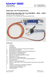
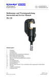
Auf dem Knapp 46 Tel.: ++49 (0)2191/907-0 D-42855 Remscheid Fax: ++49 (0)2191/907-141 _____________________________________________________________________________ Bedienungs- und Wartungsanleitung Instruction and Service Manual FHP 3 Inhaltsangabe 1. 2. 3. 4. 4.1. 4.2. 5. 5.1. 5.2. 5.3. 5.4 5.5. 5.6. 6. 7. 8. Einleitung Aufschriften Gewährleistung Beschreibung der hydraulischen Fußpumpe Beschreibung der Komponenten Beschreibung der Betätigungs- und Überwachungsfunktionen Hinweise zum bestimmungsgemäßen Gebrauch Bedienung der Pumpe Anwendung Montageanleitung Wartungshinweise Ölwechsel- und Wartungsintervalle Hinweis, welche (Ersatz-) Teile vom Kunden selber ausgewechselt werden dürfen. Verhalten bei Störungen Außerbetriebnahme/Entsorgung Technische Daten Joh.-Christoph Schütz HE.8233 Version 0.a 9/99 HE8233 Anzahl der Seiten: 15 Bedienungsanleitung FHP 3 Seite 2 ___________________________________________________________________________ Kurzinspektion vor Inbetriebnahme Bitte prüfen Sie, ob Sie alle im Lieferumfang angeführten Teile erhalten haben. Lieferumfang: 1 1 1 hydraulische Fußpumpe Typ FHP 3 2m Hochdruckschlauch mit Kupplung Bedienungsanleitung Bedienungsanleitung für die hydraulische Fußpumpe Typ FHP 3, Seriennummer ..................... 1. Einleitung • Vor Inbetriebnahme Ihre Fußpumpe lesen Sie sich die Bedienungsanleitung sorgfältig durch. • Benutzen Sie dieses Gerät ausschließlich für den bestimmungsgemäßen Gebrauch. • Diese Bedienungsanleitung ist während der gesamten Lebensdauer des Gerätes mitzuführen. • Der Betreiber muß - dem Bediener die Betriebsanleitung zugänglich machen und - sich vergewissern, daß der Bediener sie gelesen und verstanden hat. 2. Aufschriften An der Fußpumpe finden Sie einen Aufkleber mit Firmenlogo/Firmennamen, Typenangabe, Seriennummer und dem zulässigen Betriebsüberdruck. Der Hydraulikschlauch ist mit Herstellerangabe, Typ, Nennweite und Herstellungsjahr versehen. Die Nennweite kann an den letzten beiden Ziffern der Typangabe abgelesen werden. 3. Gewährleistung Die Gewährleistung beträgt bei sachgemäßer Bedienung und unter Einhaltung der geforderten regelmäßigen Kontrollen 1 Jahr ab Lieferdatum. Bedienungsanleitung FHP 3 Seite 3 ___________________________________________________________________________ 4. Beschreibung der hydraulischen Fußpumpe 4.1. Beschreibung der Komponenten Die hydraulische Fußpumpe mit unserer Typbezeichnung FHP2 besteht aus folgenden Komponenten: Bild 1 Hochdruckhydraulikschlauch Pumphebel Pos.-Nr. 5 Pos.-Nr. 1 Tabelle 1 Pos.-Nr. Bezeichnung 1 Pumphebel 2 Haltebügel 3 4 Rückstellhebel Ölstopfen 5 Hydraulikschlauch Haltebügel Pos.-Nr. 2 Ölstopfen Pos.-Nr. 4 Rückstellhebel Pos.-Nr. 3 Funktion Hebel zum Ausführen des Pumpvorganges Transportsicherung zum Fixieren des Pumphebels zum Öffnen des Rückströmventiles Schraube zum Öffnen und Schließen des Ölvorratsbehälters Stahlarmierte Hockdruckschlauchleitung zum Verbinden des Preßkopfes mit der Pumpe Referenz S 3, 4 S 3, 4, 5 S 3, 4, 5 S3 S3, 5, 11 4.2. Beschreibung der Betätigungs- und Überwachungsfunktionen Zum Entfernen der Transportsicherung wird der Pumpenhebel (Pos.-Nr. 1) nach unten in Richtung des Pumpenkörpers gedrückt und der Haltebügel (Pos.-Nr. 2) zur Seite geschwenkt. Durch Fußbetätigung des Pumpenhebels wird der Arbeitsvorgang eingeleitet. Nach kontinuierlicher Betätigung des Fußhebels schaltet die Pumpe nach einem hörbaren Klicken bei 630 bar selbständig ab. Die Pumpe ist mit einem Doppelkolben ausgestattet, der einen schnellen Vorschub und einen langsamen Arbeitshub aufweist. Nach Ansprechen des Überdruckventils wird der Kolben durch Betätigung des Rückstellhebels (Pos.-Nr. 3) der Fußpumpe zurückgefahren. Der Druckaufbau kann jederzeit an einem an der Pumpe auf Wunsch angebrachten Manometer verfolgt werden. Bedienungsanleitung FHP 3 Seite 4 ___________________________________________________________________________ 5. Hinweise zum bestimmungsgemäßen Gebrauch Es muß darauf geachtet werden, daß das Pumpaggregat standsicher auf einer ebenen Fläche mit einem maximalen Neigungswinkel von 15° aufgestellt wird. In Verbindung mit einem 2 m Hochdruckschlauch (Pos.-Nr. 5) ist das Arbeiten im Kabelgraben nicht möglich. Für diese Anwendung wird mindestens ein 3 m Schlauch benötigt. 5.1. Bedienung des Gerätes 1. Anschluß der Arbeitseinheit an die Fußpumpe und vollständiges Ausrollen des Hochdruckschlauches. Achtung Vorsicht beim Entriegeln und Verriegeln des Fußpedals. Das Fußpedal wird durch eine Feder im Pumpenkopf unter Vorspannung gehalten. I I Achtung Pumpe niemals ohne Arbeitseinheit betreiben! Achtung Vor Inbetriebnahme Ölstand prüfen und ggf. auffüllen. 2. Entfernen der Transportsicherung (Pos.-Nr. 2) und Positionierung der Arbeitseinheit. 3. Durchführung des Arbeitsvorganges. 4. Nach Erreichen des max. Betriebsdruckes wird der Rückstellhebel (Pos.-Nr. 3) betätigt. Achtung Desweiteren dürfen keine unter Spannung stehenden Teile bearbeitet werden. Vor Arbeitsbeginn ist ein spannungsfreier Zustand sicherzustellen. Achtung Die Kupplung darf nur im drucklosem Zustand gekuppelt werden. Das Gerät kann in einem Temperaturbereich von -20°C bis +40°C sowohl im Innen- als auch im Aussenbereich eingesetzt werden. 5.2. Anwendung Die Pumpe kann mit allen im Programm befindlichen Preß- und Schneidköpfen betrieben werden. 5.3. Montageanleitung Zum Anschluß des Preßkopfes wird der Kupplungsring zurückgezogen und auf den am Schlauch sitzenden Nippel aufgesetzt. Bedienungsanleitung FHP 3 Seite 5 ___________________________________________________________________________ 5.4. Wartungshinweise Die hydraulische Pumpe ist nach jedem Gebrauch zu reinigen und ein trockener Zustand vor Einlagerung sicherzustellen. Bitte achten Sie dabei auch stets auf die Sauberkeit von Kupplung und Kupplungsnippel. Die Pumpe ist weitgehend wartungsfrei. Lediglich der Ölstand ist regelmäßig zu kontrollieren und die Pumpe ist nach möglichen Beschädigungen zu untersuchen. Zur Ölstandskontrolle den Ölstopfen (Pos.-Nr. 4) aufdrehen und optisch den Ölstand kontrollieren. Ist der Ölstand zu niedrig, muß entsprechend Öl nachgefüllt werden. Nach erfolgter Wartung den Ölstopfen (Pos.-Nr. 4) wieder aufschrauben. Der Hydraulikschlauch und die Armaturen müssen vor und nach der Anwendung auf Beschädigungen und Undichtigkeiten hin überprüft werden. Folgende legierte Hydrauliköle können verwendet werden: Tabelle 4 Sorte Temperaturbereich Viskositätsklasse Qualitätsstufe ___________________________________________________________________________ AVIA HVI 15 -20°C bis +40°C VG 15 HLP Shell Tellus T 15 -20°C bis +40°C VG 15 HLP Mobil DTE 11 -20°C bis +40°C VG 15 HLP NUTO H 15 -20°C bis +40°C VG 15 HLP Rando HD - Z15 -20°C bis +40°C VG 15 HLP Agip OSO 15 -20°C bis +40°C VG 15 HLP BP Energol HLP 15 -20°C bis +40°C VG 15 HLP Es können auch andere vergleichbare Hydrauliköle verwendet werden. Bedienungsanleitung FHP 3 Seite 6 ___________________________________________________________________________ 5.5. Ölwechsel- und Wartungsintervalle. Es ist empfehlenswert, die Pumpe in regelmäßigen Abständen durch einen Sachkundigen zu warten, um einen einwandfreien Zustand vor dem nächsten Gebrauch zu gewährleisten. Tabelle 5 Wartungsplan: Was? Wann? wer? ________________________________________________________________ Reinigen nach jedem Gebrauch Bediener Ölstand prüfen wöchentlich Bediener Hochdruckschlauch prüfen wöchentlich Sachkundigen Hydrauliköl wechseln jährlich Werk/Sachkundigen Das Hydrauliköl ist nach spätestens einem Jahr oder bei häufigem Gebrauch nach ca. 10.000 Verpressungen komplett auszutauschen. Wir empfehlen, diesen Ölwechsel im Werk ausführen zu lassen. I Achtung Bitte verwenden Sie nur sauberes, einwandfreies Hydrauliköl (AVIA HVI 15 und andere Hydrauliköle gleicher Qualität). Achtung Hydrauliköle können Hautausschläge und andere Gesundheitsschädigungen hervorrufen. Vermeiden Sie längeren Hautkontakt. Waschen Sie sich nach jedem Kontakt gründlich. I Achtung Verschüttetes Hydrauliköl muß sofort mit Saugmaterial gebunden werden. 5.6. Hinweis welche (Ersatz-) Teile vom Kunden selber ausgetauscht werden dürfen. Innerhalb des Gewährleistungszeitraums darf vom Kunden nur das Öl gewechselt werden. I Achtung Versiegelung der Druckeinstellschraube nicht beschädigen! Führen Sie keine eigenen Reparaturen durch und entfernen Sie keine Bauteile wie Schrauben oder andere Komponenten. Bedienungsanleitung FHP 3 Seite 7 ___________________________________________________________________________ 5.7. Transport Das Hydraulikaggregat sollte, um Beschädigungen beim Transport zu vermeiden, immer in einem Transportkoffer transportiert werden. Dabei ist darauf zu achten, daß der Hydraulikschlauch (Pos.-Nr. 5) ordentlich aufgerollt wird. Der Mindestknickradius von max. 70 mm darf nicht unterschritten werden. 6. Verhalten bei Störungen Erreicht die Pumpe nicht Ihren vollen Druck, so kann Luft in das System eingedrungen sein. Abhilfe: Halten Sie bitte die Arbeitseinheit tiefer als die Pumpe und betätigen Sie den Pumphebel. Nach dem vollständigen Rücklauf des Kolbens Ölstopfen öffnen damit die Luft aus dem Tank entweichen kann. Diesen Vorgang wiederholen Sie bitte 2-3 mal. Erreicht die Pumpe dann noch nicht den vollen Druck, so muß der Entlüftungsvorgang wiederholt werden. Tritt Hydrauliköl an der Pumpe aus, muß das jeweilige Bauteil oder ggf. das gesamte Gerät zur Reparatur ins Werk eingeschickt werden. 7. Außerbetriebnahme/Entsorgung Auch bei qualitativ hochwertigen Geräten ist irgendwann der Zeitpunkt gekommen, an dem die Entsorgungsfrage gestellt werden muß. Die Entsorgung der einzelnen Komponenten des Gerätes muß getrennt erfolgen. Dabei muß zuerst das Öl abgelassen und an speziellen Abnahmestellen entsorgt werden. Achtung Hydrauliköle stellen eine Gefahr für das Grundwasser dar. Unkontrolliertes Ablassen oder unsachgemäße Entsorgung steht unter Strafe. (Umwelthaftungsgesetz) Als nächstes muß der Schlauch abgeschraubt werden und das im Schlauch befindliche Öl mit dem Öl aus der Pumpe entsorgt werden. Auch der Schlauch muß als ölverschmutztes Betriebsmittel speziell entsorgt werden. Die restlichen Teile des Gerätes müssen unter Beachtung der geltenden Umweltstandards entsorgt werden. Wir empfehlen wegen möglicher Umweltverschmutzung die Entsorgung durch zugelassene Fachunternehmen vornehmen zu lassen. Eine kostenfreie Rücknahme des Altgerätes durch den Hersteller kann nicht zugesagt werden. Bedienungsanleitung FHP 3 Seite 8 ___________________________________________________________________________ 8. Technische Daten Temperaturbereich des Hydrauliköls: Schlauchlänge: Hydrauliköl: Betriebsdruck: Fördermenge im Niederdruckbereich: Hochdruckbereich: Eingefüllte Ölmenge nutzbares Ölvolumen: Gewicht: (inkl. Öl) -20°C bis +40°C 2m "AVIA HVI 15" 700 bar 52,3 cm³ 2,1 cm³ 1l ca. 700 cm³ 10,500 kg Symbole Sicherheitstechnische Hinweise Bitte unbedingt beachten, um Personenund Umweltschäden zu vermeiden. I Anwendungstechnische Hinweise Bitte unbedingt beachten, um Schäden am Gerät zu vermeiden. Anmerkung Diese Bedienungsanleitung können Sie jederzeit kostenlos unter der Bestell-Nr. HE.8233 bei uns bestellen. Auf dem Knapp 46 Tel.: ..49 (0)2191/907-0 D-42855 Remscheid Fax: ..49 (0)2191/907-141 ___________________________________________________________________________ Instruction Manual FHP 3 Index 1. 2. 3. 4. 4.1. 4.2. 5. 5.1. 5.2. 5.3. 5.4. 5.5. 5.6. 5.7. 6. 7. 8. Introduction Labels Warranty Description of the hydraulic pump Description of the components Description of the operation Remarks with respect to the determined use Operation of the unit Explanation of the application range Mounting instructions Service and Maintenance instructions Oil changing cycles Storage and transport of the unit Reference as to which (spare-) parts can be exchanged by the customer Troubleshooting Putting out of action/waste disposal Technical data Joh.-Christoph Schütz HE.8233 Version 0.a 9/99 HE8233 Anzahl der Seiten: 15 Instruction Manual FHP 3 page 10 _____________________________________________________________________________ Brief inspection before putting into service Please check immediately if you received all parts mentioned in our basic supply. Basic supply: 1 1 1 hydraulic foot pump Type FHP 3 2 m high pressure hose with coupling instruction manual Instruction Manual for the hydraulic unit Type FHP 3, Serial-No. ............................ 1. Introduction Before starting to use the pump please read the instruction manual carefully. Use this pump exclusively for its determined use. Mounting and assembly of connecting material with the help of this pump must only be performed by specially trained personnel. The minimum age is 16 years. This instruction manual must be carried along during the entire life span of that pump. The operator must - guaranty the availability of the instruction manual for the user and - make sure, that the user has read and understood the instruction manual. 2. Labels On the labels fixed on the unit you’ll find the type specification, name of the manufacturer and/or the company logo and the serial number. 3. Warranty If correct operation is guaranteed and regular service is provided our warranty is 1 year from the time of delivery. Instruction Manual FHP 3 page 11 _____________________________________________________________________________ 4. Description of the hydraulic pump 4.1. Description of the components The hydraulic pump type FHP 3 consists of the following components: picture 1 Pump lever Pos.-No. 1 High pressure hose Pos.-No. 3 Table 1 Pos.-No. Description 1 Pump lever 2 3 4 Hook Release lever Oil plug 5 High pressure hose Hook Pos.-Nr. 2 Oil plug Pos.-Nr. 4 Release lever Pos.-Nr. 5 Function To actuate the pump To fix the pump lever for easy transportation To release the pressure of the pump Screw for the oil reservoir to service the pump Steel armed hydraulic high pressure hose Reference pp.11, 12, 14 pp. 11, 12 p. 11 p. 12 pp. 12, 13 4.2. Description of the operation In order to release the pump lever (Pos.-No. 1) the hook (Pos.-No. 2) must be disengaged by pushing the lever towards the body of the pump so that the hook (Pos.-No. 2) can be pushed aside and thus releasing the pump lever. By actuating the pump lever with the foot the crimping cycle will be initiated. After continuously actuating the pump lever the pump will switch off automatically when reaching the max. operating pressure at 630 bar. Reaching this point will be indicated by an audible „click“. The pump has a double piston which allows a fast approach of the dies/blades to the cable in a low pressure mode. When the compression starts the pump will automatically switch over to the high pressure mode. After reaching the max. operating pressure the piston can be returned into the starting position by actuating the release lever (Pos.-No.3). If a pressure pick up is available the pressure increase can be observed. Instruction Manual FHP 3 page 12 _____________________________________________________________________________ 5. Remarks with respect to the determined use The pump must be positioned on an even surface with a max. angle of 15°. In combination with a 2 m high-pressure hose it is not possible to work in a cable trench. For this application at least a 3m high-pressure hose is needed. 5.1. Operation of the unit 1.) First you have to connect the crimping head to the high pressure hose (Pos.-No. 5) and roll out the hose completely. I Attention Don’t actuate the pump without the crimping head. I Attention Before operating the unit the oil level must be checked and adjusted if necessary. 2.) Remove the hook (Pos.-No. 2) and bring the remote head into position. 3.) Actuate the pump lever (Pos.-No. 1) continuously until the remote head has terminated the intended operation. After this process has been completed the release button must be actuated to return the piston into its starting position. 5.2. Explanation of the application range The pump can be operated with the all Klauke crimping and cutting heads. 5.3. Mounting instructions The remote heads must be mounted on the hose by retracting the sleeve of the coupling and pushing it onto the nipple. 5.4. Service and maintenance instruction The hydraulic pump must be cleaned and dried after each use. The pump is basically maintenance free, only the oil level must be checked regularly and it has to be inspected for possible damages and wear. Check the oil level of the pump unit. If the oil level proves to be unsatisfactory additional oil has to be added. To do that open the oil filler plug (Pos.-No. 4) and fill in the oil. After servicing the oil filler plug must be screwed on again. The hydraulic hose (Pos.-No. 5) and the armature must be checked for damage and leakage. Instruction Manual FHP 3 page 13 _____________________________________________________________________________ Attention Spilled hydraulic oil has to be absorbed immediately. After one year we recommend sending the pump in to the manufacturer for an inspection. 5.5. Oil changing cycles The hydraulic oil has to be completely changed annually or after 10.000 crimping/cutting cycles if the pump is used frequently. We recommend to have the service done in specialised companies where the safe disposal of the oil is guaranteed. I Attention Please use only clean, proper hydraulic oil. (AVIA HVI 15 and other hydraulic oils of similar quality) The following hydraulic oils are suitable: Sort Temperature range Viscosity Class Quality level ________________________________________________________________________ AVIA HVI 15 -20°C to +40°C VG 15 HLP Shell Tellus T 15 -20°C to +40°C VG 15 HLP Mobil DTE 11 -20°C to +40°C VG 15 HLP NUTO H 15 -20°C to +40°C VG 15 HLP Rando HD - Z15 -20°C to +40°C VG 15 HLP Agip OSO 15 -20°C to +40°C VG 15 HLP BP Energol HLP 15 -20°C to +40°C VG 15 HLP Attention Hydraulic oils can cause cutaneous eruption (eczema) or other health hazards. Avoid longer skin contact. Wash your hands carefully after each contact. 5.6. Storage and transport of the pump In order to protect the pump unit against damages it has to be cleaned carefully after heavy duty operations. The hydraulic pump is supplied with a hook (Pos.-No. 2) to hold the pump lever down for easier transportation. The hydraulic hose (Pos.-No. 5) is the most vulnerable part of the pump and has to be handled with care. The minimum bending radius should not be lower than 70 mm. 5.7. Reference as to which spare parts can be exchanged by the customer Within the determined use of the pump only the oil are permitted to be changed by the customer. I Attention Do not damage the seals of the pump. Do not attempt to repair the pump yourself, and do not remove any parts such as screws and other components. Instruction Manual FHP 3 page 14 _____________________________________________________________________________ 6. Troubleshooting a.) If the pump doesn’t reach the final operating pressure air may have penetrated the system. => Hold the crimping unit lower than the pump and actuate the pump lever (Pos.No 1) until the dies are completely closed. Repeat this procedure 2 or 3 times. If the pump is still not reaching the full pressure repeat this process again until the pump works properly. Should the malfunction not be corrected by this the pump must be returned to the manufacturer. b.) The pump loses oil. => Return the pump to the manufacturer. Do not open or destroy the seal of the pump. 7. Putting out of service/waste disposal After many years of intensive use even a high quality pump has finally to be put out of service. The disposal of the various components of the pump have to be treated separately. The first step is to dispose of the oil at special delivery points. Attention Hydraulic oils represent a danger for the ground water. Uncontrolled draining of oil or improper disposal is under penalty of applicable environmental liability laws. Next dismantle the high-pressure hose and dispose of the oil in the hose with the oil in the pump. The emptied hose needs also to be disposed of at a special delivery point. The remaining parts of the unit can currently be disposed of as scrap-metal. Because of possible environmental damages we recommend the disposal of the pump by professional companies. A return of the old unit free of charge to the manufacturer cannot be granted. Instruction Manual FHP 3 page 15 _____________________________________________________________________________ 8. Technical Data Hose length: Hydraulic oil: Oil capacity: Usuable oil capacity: Flow - Low pressure: - High pressure: Temperature range (hydraulic oil): Weight of the complete unit with oil: Max. operation pressure: 2m „AVIA HVI 15“ 1l ca. 700 cm³ Hydraulic pump: double piston for two speed operations 52,3 cm³ 2,1 cm³ -20°C to +40°C approx. 10,5 kg 700 bar Symbols Safety warnings Please do not disregard these instructions in order to avoid human injuries and environmental damages. I Operational warnings Please do not disregard them to avoid damaging the pump unit. Note This Instruction Manual can be ordered free of charge. The part # is HE.8233.