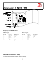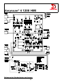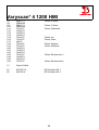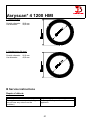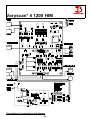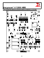
1
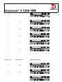
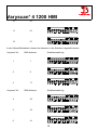
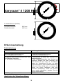
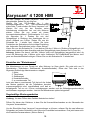
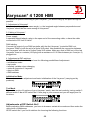
Varyscan* 4
1200 HMI
Made in Germany by JB-lighting
JB lighting Lichtanlagentechnik GmbH Sallersteigweg 15, 89134 Blaustein, Tel. +49 7304 9617-0, Fax. -99
Varyscan* 4 1200 HMI
Bedienungsanleitung
deutsch
2
Seite
05-38
Varyscan* 4 1200 HMI
Operating Instructions
english
3
Page
39-70
Varyscan* 4 1200 HMI
Bedienungsanleitung
4
Varyscan* 4 1200 HMI
Varyscan* 4
1200 HMI
Made in Germany by JB-lighting
Version 1.1
Vorwort
Sie haben sich für den Kauf des Varyscan* 4 1200 HMI von JB-lighting entschieden.
Vielen Dank für das entgegengebrachte Vertrauen.
5
Varyscan* 4 1200 HMI
Der Varyscan* 4 1200 HMI gibt Ihnen viele Möglichkeiten, Ihre gewünschten Effekte zu
realisieren. Lesen Sie zuerst in aller Ruhe diese Bedienungsanleitung durch, denn sie enthält
Informationen, die Ihnen gewährleisten, Ihren Varyscan* voll zu nutzen.
Viel Spaß und gute Shows wünscht Ihnen
JB-lighting
Inhaltsverzeichnis
A
Bedienungsanleitung
Deckblatt
Vorwort
Inhaltsverzeichnis
6
7
6
Varyscan* 4 1200 HMI
Abbildung Varyscan* 1200 HMI
Rückansicht und Lage der Bedienelemente
Auspacken der Varyscan* Anlage
Brenner einsetzen / auswechseln
Inbetriebnahme der Anlage
DIP-Schaltereinstellungen
Betriebsartenwahl
DMX-Adresseneinstellung
Eine bestimmte DMX-Adresse einstellen
Auswechseln der Gobos
GOBO Maße
8
9
10
10
11
11
12
14
17
18
18
B Serviceanleitung
Fehlerbehebung
Abgleichen des Spiegelanschlages
Einstellen der "Motorbremse"
Regelmäßige Wartungsarbeiten
Allgemeine Information zum DMX512 Protokoll
Kanalbelegung Varyscan* 4 1200 HMI
Belegung DMX-IN / DMX-OUT
Technische Daten
Epromwechsel / Software Update
Stromlaufplan Varyscan* 4 1200 HMI
Belegung der Steckerleisten und Jumper
Stückliste Platine VS4 1200 HMI
Bestückungsplan
Abbildung VS4 1200 HMI
7
19
19
20
20
21
22
30
30
30
31
32
33
36
Varyscan* 4 1200 HMI
Rückansicht und Lage der Bedienelemente
8
Varyscan* 4 1200 HMI
Belegung der DMX-Buchsen
DMX-Eingang
Pin Nr.
1
2
3
4
5
Signal
Ground
DMX DMX +
frei
+5V
DMX-Ausgang
Kabelfarbe
schwarz
weiß
rot
gr/sw
Pin Nr.
1
2
3
4
5
Auspacken der Varyscan* Anlage
Vor Ihnen befindet sich die komplette Varyscan*-Anlage.
9
Signal
Ground
DMX DMX +
frei
frei
Kabelfarbe
schwarz
weiß
rot
Varyscan* 4 1200 HMI
Entnehmen Sie zuerst alle Teile aus den Kartons.
•
•
Varyscan* 1200 HMI
diese Anleitung
Prüfen Sie, ob alle Teile in der Lieferung enthalten sind.
Sollten Sie einen Transportschaden feststellen oder sollten Sie feststellen, daß Teile fehlen,
teilen Sie dies bitte sofort dem Transportunternehmen bzw. Ihrem Händler mit.
Die Verpackung Ihrer Varyscan* wird -wenn möglich- aus Umweltgründen mehrfach verwendet.
Sie erhalten bei Rückgabe der Verpackungen eine Teilgutschrift.
Bitte machen Sie von der Rückgabe im Sinne unserer Umwelt Gebrauch. Wir bitten Sie aus
diesem Grunde auch um Verständnis, falls Sie evtl. eine gebrauchte Verpackung bzw. Inlay
erhalten sollten.
Brenner einsetzen/auswechseln
HINWEIS: Vor dem Öffnen Netzstecker ziehen!!
Öffnen Sie den Deckel (Aufschrift Varyscan 4 1200HMI) Ihres
Varyscan* mit einem passenden Kreuzschlitzschraubendreher
und heben Sie diesen ab. Jetzt können Sie im hinteren Drittel
des Varyscan* die Brennerfassung erkennen.(Skizze Seite 4)
Lösen Sie nun die beiden Muttern 1 und 2 und entnehmen Sie
den Brenner aus der Fassung. Setzen Sie nun den neuen HMIBrenner in die Fassung ein und drehen die beiden Muttern 1
und 2 von Hand fest. Der "Absaugstutzen" des Brenners darf auf keinen Fall in Richtung des
Hohlspiegels bzw. in Richtung der Linsen zeigen (Skizze Seite 4), er sollte in Richtung des
Bodenblechs oder des Deckels zeigen. Achten Sie auf einen festen Sitz des Brenners.
Achtung: Berühren Sie niemals beim 1200HMI-Brenner den Glaskörper selbst!
Eine Justierung des Brenners entfällt.
Inbetriebnahme der Anlage
1. Varyscan* aufhängen
Um die optimale Funktionsfähigkeit der Varyscan* auszuschöpfen, sollten Sie die Spots so
hoch wie möglich aufhängen.
10
Varyscan* 4 1200 HMI
2. Varyscan* einstellen
Alle Spots sollten im selben Winkel hängen, das heißt der gedachte Winkel zwischen Lot und
Varyscan* sollte bei allen Varyscan* gleich sein.
3. Varyscan* verkabeln
Spannungsversorgung:
Lassen Sie von einem Fachmann an das offene Ende des Anschlußkabels einen SchukoStecker anbringen, oder lassen Sie das Kabel direkt an 230 Volt 50 Herz anschließen.
Signalverkabelung:
Verbinden Sie den Ausgang Ihres DMX-Controllers mit dem ersten Varyscan* (Controller DMXOut; Varyscan* DMX-In) mit Hilfe eines 5poligen XLR-Kabels. Stellen Sie nun mit Hilfe weiterer
5pol-XLR Kabel die Verbindung zwischen den Varyscan* her. Achten Sie darauf, daß beim
letzten Scan im DMX-Out ein Endstecker (XLR-Stecker mit einem Widerstand von 100 Ohm
zwischen Pin 2 und 3) steckt.
4. Einstellen der DIP-Schalter
Sie haben an den DIP-Schaltern Nr.1 und Nr.2 folgende Einstellmöglichkeiten:
• Initialisierungsmodus
• Testmodus
• Farbwechsel stufenlos
• Kanalauswahl des Varyscan*
• Reset über DMX
• DMX-Adresse
Initialisierungsmodus:
Dieser Modus dient zur Einstellung und zur Grundinitialisierung des Varyscan* (wird vom
Hersteller durchgeführt.)
Testmodus:
Um mit einfachen Mitteln die Funktionvielfalt Ihres Varyscan* zu sehen, schalten Sie den
Varyscan* in den Testmodus, indem Sie am DIP-Schalter Nr.2 den Schalter 3 auf off und
den Schalter 2 auf on
stellen
(siehe
auch
Typenschild). Jetzt stecken
Sie den Scanner ein, und er
zeigt Ihnen einen großen Teil
seiner Funktionen.
Einstellungen am DIP-Schalter NR.2
Bevor wir zur DMX-Adresseneinstellung kommen, müssen wir zuerst am DIP-Schalter Nr. 2
eine bestimmte Betriebsart auswählen, um danach die richtige Adressauswahl zu treffen.
Sie haben am DIP-Schalter Nr.2 4 Schalter, mit denen Sie folgende Funktionen auswählen
können.
Farbwechsel stufenlos: DIP-Schalter Nr.2 Schalter 1
11
Varyscan* 4 1200 HMI
d.h. wenn diese Funktion eingeschaltet ist, entspricht jeder DMX-Wert zwischen 0 und 128
einer Farbradstellung, Sie können somit nicht nur Halbfarben erzeugen, sondern auch 1/3-2/3
Farben oder 1/4-3/4Farben usw. Um diese Funktion zu wählen, schalten Sie am DIP-Schalter
Nr.2 den Schalter 1 auf on (siehe auch Typenschild)
ist der Schalter 1 auf off, so haben Sie nur Voll- bzw. Halbfarben.
Betriebsartenwahl: DIP-Schalter Nr.2 Schalter 2 und 3
Es stehen Ihnen insgesamt 3 DMX-Kanal-Formate zur Verfügung, die im folgenden genauer
erklärt werden (Kurzbeschreibung siehe Typenschild).
1. JB-lighting 8 Kanal
Kanal 1
X-Achse
Kanal 2
Y-Achse
Kanal 3
Gobo
Kanal 4
Farbe
Kanal 5
Shutter/Dimmer
Kanal 6
Iris
Kanal 7
drehbare Gobos (Positionierung und Rotation)
Kanal 8
Effektrad
DIP-Schaltereinstellung: DIP-Schalter Nr.2 Schalter 2 und 3 off
2. 6 Kanal (Clay Paky - Goldenscan 3 kompatibel)
Kanal 1
Kanal 2
Kanal 3
Kanal 4
Kanal 5
Kanal 6
Iris und Gobodreh
Farbe
Gobo- und Effektrad
Dimmer / Shutter
X-Achse
Y-Achse
DIP-Schalterstellung: DIP-Schalter Nr.2 Schalter 2 off Schalter 3 on
12
Varyscan* 4 1200 HMI
3. JB-lighting 6 Kanal
Kanal 1
Kanal 2
Kanal 3
Kanal 4
Kanal 5
Kanal 6
X-Motor
Y-Motor
Gobo
Farbe
Dimmer/Shutter
Iris / Gobodreh
DIP-Schaltereinstellung: DIP-Schalter Nr.2 Schalter 2 und 3 on
Reset über DMX: DIP-Schalter Nr.2 Schalter 4
Wenn Sie an Ihren Varyscan* von Ihrem DMX-Pult aus einen Reset durchführen wollen, so
müssen Sie am DIP-Schalter Nr. 2 den Schalter 4 auf on stellen. Jetzt haben Sie die
Möglichkeit, wenn Sie über den Gobokanal den DMX-Wert 255 übertragen, an Ihrem Varyscan*
einen Reset durchzuführen.
Ist am DIP-Schalter Nr.2 der Schalter 4 auf off, so ist der Reset über DMX ausgeschaltet.
DMX-Adresse einstellen: DIP-Schalter Nr. 1 Schalter 1 bis 9
Je nach gewählter Betriebsart müssen nun die DMX-Adressen wie folgt eingestellt werden. Die
Adressierung erfolgt nach dem binären Zahlensystem und muß bei den beiden Sechs-KanalBetriebsarten in 6er-Schritten erfolgen.
Varyscan* Nr.
DMX-Adresse
1
1
Schaltereinstellung
13
Varyscan* 4 1200 HMI
2
7
3
13
4
19
5
25
6
31
7
37
Varyscan* Nr.
DMX-Adresse
8
43
9
49
Schaltereinstellung
14
Varyscan* 4 1200 HMI
10
55
11
61
12
67
In der 8-Kanal-Betriebsart müssen die Adressen in 8er-Schritten eingestellt werden.
Varyscan* Nr.
DMX-Adresse
1
1
2
9
3
17
Varyscan* Nr.
DMX-Adresse
4
25
5
33
6
41
Schaltereinstellung
Schaltereinstellung
15
Varyscan* 4 1200 HMI
7
49
8
57
9
65
10
73
11
81
12
89
Bestimmung der DIP-Schaltereinstellung für bestimmte DMX-Adressen
Die einzelnen DIP-Schalter entsprechen den oben angezeigten Werten. Soll nun eine
bestimmte DMX-Adresse eingestellt werden, so muß diese nur aus den einzelnen Werten
zusammengezählt werden.
Beispiel:
DMX-Adresse "45"
32 + 8 + 4 + 1 = 45
SW6 SW4 SW3 SW1
on on
on
on
Die restlichen DIP-Schalter SW9 SW8 SW7 SW5 SW2 bleiben auf "OFF".
16
Varyscan* 4 1200 HMI
Auswechseln der Gobos
Öffnen Sie den Deckel mit der Beschriftung Varyscan* 4 1200 HMI, indem Sie die sechs
Kreuzschlitzschrauben herausdrehen. Jetzt können Sie die Gobos am Goborad aus der
Halterung drücken und die neuen Gobos einsetzen. Achten Sie darauf, daß das Gobo exact mit
den Schlitzen in der Halterung einrastet. Wenn das Gobo richtig eingesetzt ist, läßt es sich
ganz leicht in der Halterung bewegen. Jetzt können Sie den Deckel wieder schließen.
Gobo-Maße:
Sie haben an Ihrem Varyscan* 4 1200 HMI die Möglichkeit zwei verschiedene Gobo-Maße
einzusetzen.
1. Gobos im JB-Format:
Außendurchmesser:
Nutzdurchmesser:
68,0 mm
49,0 mm
Vorteil: Durch die Ausklinkungen mit 1mm Tiefe mit 120°-Teilung ist gewährleistet, daß sich die
Gobos in der Gobohalterung auf dem Goborad nicht wie bei anderen Herstellern drehen.
17
Varyscan* 4 1200 HMI
2. Standardformat: (M-Size)
Außendurchmesser:
Nutzdurchmesser:
66,0 mm
49,0 mm
B Serviceanleitung
Fehlerbehebung
Fehler
Behebung des Problems
Das Gerät arbeitet überhaupt nicht
16 Ampere-Sicherung des Gerätes
(kein Lüftergeräusch zu hören)
austauschen (Skizze Seite 5)
Der Brenner des Gerätes leuchtet nicht, aber 1. Der Brenner ist defekt, der Brenner muß
die Elektronik funktioniert,
getauscht werden
d.h. die Motoren funktionieren
2. Der Temperaturschalter des Gerätes hat
ausgelöst. Stecken Sie Ihren Varyscan* aus
und stecken Sie Ihn nach ca. 15 Minuten
wieder ein. Kontrollieren Sie nun, ob beide
Lüfter noch laufen, und ob diese sauber sind.
Sollte ein Lüfter defekt sein, so lassen Sie
diesen von einem Fachmann oder dem
Hersteller austauschen. Sollte der Scanner
immer wieder abschalten, wenden Sie sich
bitte an Ihren Händler
DMX-Eingang funktioniert nicht
DIP-Schaltereinstellung kontrollieren
Abgleichen des Spiegelanschlages
18
Varyscan* 4 1200 HMI
Um den Spiegel an Ihrem Varyscan* 1200 HMI
abzugleichen, gehen Sie wie folgt vor:
Stellen Sie am DIP-Schalter Nr. 1 den
Initialisierungsmodus
ein
(DIP-Schalterstellung
siehe Seite 7) und schalten Sie Ihren Varyscan* ein.
Warten Sie nun, bis der Scanner seine
Initialisierung durchlaufen hat und alle Motoren
stehen. Lösen Sie nun zuerst mit einem
Innensechskantschlüssel (Schlüsselweite 2,0 mm)
die Schraube Nr. 1. Drehen Sie nun den
Spiegelbügel in Richtung des Anschlages bis zu
einem Abstand von 0,5mm. Ziehen Sie nun die
Schraube Nr. 1 wieder fest. Achten Sie beim
Festziehen der Schraube auf die richtige Einstellung
des federnden Druckstückes (siehe untere Skizze).
Lösen Sie nun die Schraube Nr. 2 und drehen Sie den Y-Motor in Richtung Spiegelbügel und
stellen somit zwischen dem Anschlag und dem Spiegelbügel einen Abstand von 0,5 mm ein.
Achtung: Achten Sie darauf, daß der Y-Motor nicht vom Spiegelbügel weggedrückt wird, da
sonst die Klemmung des Y-Motors nicht mehr funktioniert. Die Reibefläche des Motors muß
ganz am Kunststoffdrehteil anliegen. Ziehen Sie nun die Schraube Nr. 2 wieder fest.
Einstellen der "Motorbremse"
Die Motorbremse ist vom Prinzip bei allen Motoren im Scan gleich. Sie setzt sich aus 3
Spezialteilen (Tellerfedern, Stahllaserteil, Kunststoffscheibe). Diese drei Teile sind in der
folgenden Reihenfolge übereinander zu stapeln:
1. Motor
2. Telerfedern
3. Stahllaserteil
4. Kunststoffscheibe
5. zu montierendes Teil.
Jetzt wird das zu montierende Teil fest auf die Achse
des Motors gedrückt, bis die Tellerfedern komplett
zusammengedrückt sind, anschließend muß das zu
befestigende Teil um ca. 0,5mm zurückgezogen werden und die Befestigungsschraube(n)
muß/müssen angezogen werden. Jetzt ist die Motorbremse optimal eingestellt
Regelmäßige Wartungsarbeiten
Achtung: Vor dem Öffnen des Gerätes Netzstecker ziehen!
Öffnen Sie hierzu das Gehäuse, in dem Sie die Kreuzschlitzschrauben an der Oberseite des
Varyscan* herausdrehen.
Um die Einschübe Ihres Varyscan* herausnehmen zu können, müssen Sie die zwei silbernen
Schrauben auf jedem Seitenteil in der Höhe der Einschübe herausdrehen. Erst jetzt lassen sich
die Einschübe herausnehmen. (Skizze Seite 4)
19
Varyscan* 4 1200 HMI
Achtung:
Vergessen Sie nicht beim Abschluß Ihrer Wartungsarbeiten die Einschübe wieder
zu verriegeln, indem Sie die silbernen Schrauben wieder vorsichtig hineindrehen.
1. Reinigung aller optischen Teile:
Sie sollten in regelmäßigen Abständen die optischen Teile des Varyscan* reinigen, um wieder
die maximale Helligkeit des Scanners herzustellen. Entnehmen Sie, nachdem Sie das Gehäuse
wie oben beschrieben geöffnet haben, nun den Effektradeinschub (Skizze Seite 4) und legen
diesen vor Ihnen auf eine Unterlage. Nehmen Sie nun ein fusselfreies Tuch und etwas
Fensterputzmittel und reinigen Sie die Effektfilter auf dem Effektrad.
Anschließend reinigen Sie noch die beiden Linsen (Skizze Seite 4). Um das Objektiv leichter
reinigen zu können, lösen Sie die Objektivhalteschraube und entnehmen das Objektiv. Nun
können Sie es leicht innen und außen reinigen. Entnehmen Sie nun noch den
Farbradeinschub, um die Farbfilter zu reinigen. Setzen Sie anschließend das Objektiv, den
Effektradeinschub und den Farbradeinschub wieder ein. Vergessen Sie nicht, die
Objektivhalteschraube wieder anzuziehen.
2. Reinigung der Lüftung:
Sie sollten in regelmäßigen Abständen die Funktion der Lüfter überprüfen. Vor allem sollten Sie
darauf achten, daß die Lufteinlässe und das Innere des Varyscan* frei von Fusseln und
sonstigem Staub sind. Hierzu öffnen Sie am besten beide Deckel des Varyscan*, indem Sie die
Kreuzschlitzschrauben an den Deckeln herausdrehen. Jetzt saugen Sie Ihren Varyscan* mit
einem Staubsauger vorsichtig aus. Schrauben Sie nun die beiden Deckel wieder zu. Achten Sie
darauf , daß Sie für den kleineren Deckel wieder die Blechschrauben verwenden.
Achtung:
Achten Sie darauf, daß Sie beim Reinigen des Scanners keine Teile verbiegen
oder beschädigen.
3. Ölen der drehbaren Gobos
Besorgen Sie sich eine handelsübliche Spritze mit einer dünnen Nadel (Schleifen Sie die Spitze
stumpf - keine Verletzungsgefahr!!) und befüllen Sie diese mit unserem Spezialöl. Verwenden
Sie auf keinen Fall ein anderes Öl, da unser Öl speziell angemischt wird. Spritzen Sie nun
das Öl zwischen die Messingzahnräder und die Messingscheibe und drehen Sie dabei von
Hand die drehbaren Gobos.
Achtung: Nicht zuviel Öl verwenden!!
Allgemeine Informationen zum DMX512-Protokoll
Das DMX512-Protokoll ist wie man aus dem Namen schon erkennen kann in 512 Adressen
eingeteilt. Über diese 512 Adressen kann frei verfügt werden. Um nun verschiedene Geräte an
einen DMX-Controller anschließen zu können, muß zuerst die Anzahl der DMX-Kanäle für
jedes Gerät ermittelt werden. Die Kanalbelegung eines Scanners könnte beispielsweise wie
folgt aussehen.
Kanal 1
X-Bewegung
Kanal 2
Y-Bewegung
Kanal 3
Gobo / Effektrad
Kanal 4
Farbe
20
Varyscan* 4 1200 HMI
Kanal 5
Kanal 6
Shutter / Dimmer
Iris / Gobopositionierung / Goborotation
Damit nun nicht jedes angeschlossene DMX-Gerät die gleichen Funktionen ausführt, werden
die Geräte hintereinander adressiert; d.h. das Erste verwendet die ersten sechs Adressen (gilt
für ein Gerät mit sechs Kanälen) und das Zweite verwendet die nächsten sechs Adressen
(Gerät mit sechs Kanälen) der 512 DMX-Adressen (Beispiel Varyscan* siehe Seite 10).
Kanalbelegung Varyscan* 4 1200 HMI
1. JB lighting 8 Kanäle
Kanal 1
Kanal 2
Kanal 3
Kanal 4
Kanal 5
Kanal 6
Kanal 7
Kanal 8
X-Bewegung
Y-Bewegung
Gobo
Farbe
Shutter / Dimmer
Iris
drehbare Gobos (Positionierung und Rotation)
Effektrad
Kanal 1 = x (pan) 170 Grad
Kanal 2 = y (tilt) 90 Grad
Kanal 3 = Gobo
Gobo 0 (Beam)
Gobo 1
Gobo 2
Gobo 3
Gobo 4
wenn am DIP-Schalter Nr. 2 Schalter 4 auf "ON"
Gobo 4
Reset
Kanal 4 = Farbe
Farbe 0 (weiß)
Farbe 1
Farbe 2
Farbe 3
Farbe 4
Farbe 5
DMX
DMX
DMX
DMX
DMX
-
DMX 128
DMX
DMX
DMX
DMX
DMX
DMX
DMX
21
000
032
064
096
128
000
008
016
024
032
040
031
063
095
127
255
- 254
255
-
007
015
023
031
039
047
Varyscan* 4 1200 HMI
Farbe 6
Farbe 7
Farbe 8
Farbe 9
Farbe 10
Farbe 11
Farbe 12
Farbe 13
Farbe 14
Farbe 15
Farbraddreh - Geschwindigkeit 1(langsam)
Farbraddreh - Geschwindigkeit 7(schnell)
Kanal 5 = Dimmer / Shutter
Shutter Dimmer zu --> Blackout
Dimmer erstes Licht zu erkennen
Dimmer
Dimmer voll offen
Shutter schlagartig offen
Shuttersequenz 0,98 Blitze/sec
Shuttersequenz 1,04 Blitze/sec
Shuttersequenz 1,16 Blitze/sec
Shuttersequenz 1,23 Blitze/sec
Shuttersequenz 1,33 Blitze/sec
Shuttersequenz 1,43 Blitze/sec
Shuttersequenz 1,52 Blitze/sec
Shuttersequenz 1,60 Blitze/sec
Shuttersequenz 1,67 Blitze/sec
Shuttersequenz 1,77 Blitze/sec
Shuttersequenz 1,85 Blitze/sec
Shuttersequenz 1,96 Blitze/sec
Shuttersequenz 2,17 Blitze/sec
Shuttersequenz 2,27 Blitze/sec
Shuttersequenz 2,50 Blitze/sec
Shuttersequenz 2,70 Blitze/sec
Shuttersequenz 3,10 Blitze/sec
Shuttersequenz 3,50 Blitze/sec
Shuttersequenz 3,63 Blitze/sec
Shuttersequenz 4,00 Blitze/sec
Shuttersequenz 4,65 Blitze/sec
Shuttersequenz 4,88 Blitze/sec
Shuttersequenz 5,26 Blitze/sec
Shuttersequenz 5,88 Blitze/sec
Shuttersequenz 6,25 Blitze/sec
Shuttersequenz 6,90 Blitze/sec
Shuttersequenz 7,14 Blitze/sec
Shuttersequenz 7,30 Blitze/sec
Shuttersequenz 7,40 Blitze/sec
Shuttersequenz 8,00 Blitze/sec
DMX
DMX
DMX
DMX
DMX
DMX
DMX
DMX
DMX
DMX
DMX
DMX
048
056
064
072
080
088
096
104
112
120
128
-
055
063
071
079
087
095
103
111
119
127
255
DMX
0
DMX
19
DMX 20 - 127
DMX 128 - 137
DMX 138 - 139
DMX 140 - 151
DMX
152
DMX
153
DMX
154
DMX
155
DMX
156
DMX
157
DMX
158
DMX
159
DMX
160
DMX
161
DMX
162
DMX
164
DMX
166
DMX
168
DMX
170
DMX
172
DMX
174
DMX
176
DMX
178
DMX
180
DMX
185
DMX
190
DMX
195
DMX
200
DMX
205
DMX
210
DMX
215
DMX
220
DMX
225
22
Varyscan* 4 1200 HMI
Shuttersequenz 8,65 Blitze/sec
Shuttersequenz 9,25 Blitze/sec
Shuttersequenz 10,0 Blitze/sec
Shutter offen
DMX
DMX
DMX
DMX 244 -
230
235
243
255
Kanal 6 = Iris
Iris (linear)
DMX 000 - 255
Kanal 7 = drehbare Gobos (Positionierung und Rotation)
0°
180°
360°
540°
Linksdrehung (schnell)
Linksdrehung (langsam)
Drehung stop
Rechtsdrehung (langsam)
Rechtsdrehung (schnell)
DMX
000
DMX
063
DMX
126
DMX
191
DMX
192
DMX
222
DMX 223 - 224
DMX
225
DMX
255
Kanal 8 = Effektrad
offen
Kunstlichtfilter
Tageslichtfilter
Prisma
Floodfilter
stufenlos von Flood bis offen
DMX
DMX
DMX
DMX
DMX
DMX
000
032
064
096
128
160
-
031
063
095
127
159
255
2. 6 Kanäle (Clay Paky Goldenscan 3 kompatibel)
Kanal 1
Iris und Gobodreh
Kanal 2
Farbe
Kanal 3
Gobo und Effektrad
Kanal 4
Dimmer / Shutter
Kanal 5
X-Achse
Kanal 6
Y-Achse
Kanal 1 = Iris und Gobodreh
Iris zu Gobo 1. Position
Iris ganz auf Gobo 1. Position
2. Goboposition
3. Goboposition
..........
360° positioniert
540° positioniert
links Dreh höchste Geschwindigkeit
links Dreh langsamste Geschwindigkeit
Dreh Stop
DMX
DMX
DMX
DMX
0
- 64
65
66
DMX
DMX
DMX
DMX
DMX 223 -
23
191
191
192
222
224
Varyscan* 4 1200 HMI
rechts Dreh langsamste Geschwindigkeit
rechts Dreh höchste Geschwindigkeit
DMX
DMX
225
255
Kanal 2 = Farbe
Farbe 0 (weiß)
Farbe 1
Farbe 2
Farbe 3
Farbe 4
Farbe 5
Farbe 6
Farbe 7
Farbe 8
Farbe 9
Farbe 10
Farbe 11
Farbe 12
Farbe 13
Farbe 14
Farbe 15
Farbraddreh - Geschwindigkeit 1(langsam)
Farbraddreh - Geschwindigkeit 7(schnell)
DMX
DMX
DMX
DMX
DMX
DMX
DMX
DMX
DMX
DMX
DMX
DMX
DMX
DMX
DMX
DMX
DMX
DMX
000
008
016
024
032
040
048
056
064
072
080
088
096
104
112
120
128
Kanal 3 = Gobo und Effektrad
weiß
Kunstlichtfilter
Tageslichtfilter
Prisma
Floodfilter
Gobo 1 weiß
Gobo 1 Kunstlichtfilter
Gobo 1 Tageslichtfilter
Gobo 1 Prisma
Gobo 2 weiß
Gobo 2 Kunstlichtfilter
Gobo 2 Tageslichtfilter
Gobo 2 Prisma
Gobo 3 weiß
Gobo 3 Kunstlichtfilter
Gobo 3 Tageslichtfilter
Gobo 3 Prisma
Gobo 4 weiß
Gobo 4 Kunstlichtfilter
DMX
DMX
DMX
DMX
DMX
DMX
DMX
DMX
DMX
DMX
DMX
DMX
DMX
DMX
DMX
DMX
DMX
DMX
DMX
0
10
20
30
40
52
65
78
91
104
117
130
143
156
169
182
195
208
221
24
-
007
015
023
031
039
047
055
063
071
079
087
095
103
111
119
127
255
-
9
19
29
39
51
64
77
90
103
116
129
142
155
168
181
194
207
220
233
Varyscan* 4 1200 HMI
Gobo 4 Tageslichtfilter
Gobo 4 Prisma
wenn am DIP-Schalter Nr. 2 Schalter 4 auf "ON"
GOBO 4 Prisma
Reset
DMX 247 - 254
DMX
255
Kanal 4 = Dimmer und Shutter
Shutter Dimmer zu --> Blackout
Dimmer erstes Licht zu erkennen
Dimmer
Dimmer voll offen
Shutter schlagartig offen
Shuttersequenz 0,98 Blitze/sec
Shuttersequenz 1,04 Blitze/sec
Shuttersequenz 1,16 Blitze/sec
Shuttersequenz 1,23 Blitze/sec
Shuttersequenz 1,33 Blitze/sec
Shuttersequenz 1,43 Blitze/sec
Shuttersequenz 1,52 Blitze/sec
Shuttersequenz 1,60 Blitze/sec
Shuttersequenz 1,67 Blitze/sec
Shuttersequenz 1,77 Blitze/sec
Shuttersequenz 1,85 Blitze/sec
Shuttersequenz 1,96 Blitze/sec
Shuttersequenz 2,17 Blitze/sec
Shuttersequenz 2,27 Blitze/sec
Shuttersequenz 2,50 Blitze/sec
Shuttersequenz 2,70 Blitze/sec
Shuttersequenz 3,10 Blitze/sec
Shuttersequenz 3,50 Blitze/sec
Shuttersequenz 3,63 Blitze/sec
Shuttersequenz 4,00 Blitze/sec
Shuttersequenz 4,65 Blitze/sec
Shuttersequenz 4,88 Blitze/sec
Shuttersequenz 5,26 Blitze/sec
Shuttersequenz 5,88 Blitze/sec
Shuttersequenz 6,25 Blitze/sec
Shuttersequenz 6,90 Blitze/sec
Shuttersequenz 7,14 Blitze/sec
Shuttersequenz 7,30 Blitze/sec
Shuttersequenz 7,40 Blitze/sec
Shuttersequenz 8,00 Blitze/sec
Shuttersequenz 8,65 Blitze/sec
Shuttersequenz 9,25 Blitze/sec
Shuttersequenz 10,0 Blitze/sec
Shutter offen
DMX
DMX
DMX
DMX
DMX
DMX
DMX
DMX
DMX
DMX
DMX
DMX
DMX
DMX
DMX
DMX
DMX
DMX
DMX
DMX
DMX
DMX
DMX
DMX
DMX
DMX
DMX
DMX
DMX
DMX
DMX
DMX
DMX
DMX
DMX
DMX
DMX
DMX
DMX
Kanal 5 = x (pan) 170 Grad
25
DMX 234 - 246
DMX 247 - 255
20
128
138
140
-
244 -
0
19
127
137
139
151
152
153
154
155
156
157
158
159
160
161
162
164
166
168
170
172
174
176
178
180
185
190
195
200
205
210
215
220
225
230
235
243
255
Varyscan* 4 1200 HMI
Kanal 6 = y (tilt) 90 Grad
3. JB lighting 6 Kanäle
Kanal 1
Kanal 2
Kanal 3
Kanal 4
Kanal 5
Kanal 6
X-Achse
Y-Achse
Gobo und Effektrad
Farbe
Dimmer / Shutter
Iris und Gobodreh
Kanal 1 = x (pan) 170 Grad
Kanal 2 = y (tilt) 90 Grad
Kanal 3 = Gobo und Effektrad
weiß
Kunstlichtfilter
Tageslichtfilter
Prisma
Floodfilter
Gobo 1 weiß
Gobo 1 Kunstlichtfilter
Gobo 1 Tageslichtfilter
Gobo 1 Prisma
Gobo 2 weiß
Gobo 2 Kunstlichtfilter
Gobo 2 Tageslichtfilter
Gobo 2 Prisma
Gobo 3 weiß
Gobo 3 Kunstlichtfilter
Gobo 3 Tageslichtfilter
Gobo 3 Prisma
Gobo 4 weiß
Gobo 4 Kunstlichtfilter
Gobo 4 Tageslichtfilter
Gobo 4 Prisma
wenn am DIP-Schalter Nr. 2 Schalter 4 auf "ON"
Gobo 4 Prisma
Reset
26
DMX
DMX
DMX
DMX
DMX
DMX
DMX
DMX
DMX
DMX
DMX
DMX
DMX
DMX
DMX
DMX
DMX
DMX
DMX
DMX
DMX
0
10
20
30
40
52
65
78
91
104
117
130
143
156
169
182
195
208
221
234
247
-
9
19
29
39
51
64
77
90
103
116
129
142
155
168
181
194
207
220
233
246
255
DMX 247 - 254
DMX
255
Varyscan* 4 1200 HMI
Kanal 4 = Farbe
Farbe 0 (weiß)
Farbe 1
Farbe 2
Farbe 3
Farbe 4
Farbe 5
Farbe 6
Farbe 7
Farbe 8
Farbe 9
Farbe 10
Farbe 11
Farbe 12
Farbe 13
Farbe 14
Farbe 15
Farbraddreh - Geschwindigkeit 1(langsam)
Farbraddreh - Geschwindigkeit 7(schnell)
DMX
DMX
DMX
DMX
DMX
DMX
DMX
DMX
DMX
DMX
DMX
DMX
DMX
DMX
DMX
DMX
DMX
DMX
Kanal 5 = Dimmer und Shutter
Shutter Dimmer zu --> Blackout
Dimmer erstes Licht zu erkennen
Dimmer
Dimmer voll offen
Shutter schlagartig offen
Shuttersequenz 0,98 Blitze/sec
Shuttersequenz 1,04 Blitze/sec
Shuttersequenz 1,16 Blitze/sec
Shuttersequenz 1,23 Blitze/sec
Shuttersequenz 1,33 Blitze/sec
Shuttersequenz 1,43 Blitze/sec
Shuttersequenz 1,52 Blitze/sec
Shuttersequenz 1,60 Blitze/sec
Shuttersequenz 1,67 Blitze/sec
Shuttersequenz 1,77 Blitze/sec
Shuttersequenz 1,85 Blitze/sec
Shuttersequenz 1,96 Blitze/sec
Shuttersequenz 2,17 Blitze/sec
Shuttersequenz 2,27 Blitze/sec
Shuttersequenz 2,50 Blitze/sec
Shuttersequenz 2,70 Blitze/sec
Shuttersequenz 3,10 Blitze/sec
Shuttersequenz 3,50 Blitze/sec
Shuttersequenz 3,63 Blitze/sec
DMX
0
DMX
19
DMX 20 - 127
DMX 128 - 137
DMX 138 - 139
DMX 140 - 151
DMX
152
DMX
153
DMX
154
DMX
155
DMX
156
DMX
157
DMX
158
DMX
159
DMX
160
DMX
161
DMX
162
DMX
164
DMX
166
DMX
168
DMX
170
DMX
172
DMX
174
DMX
176
27
000
008
016
024
032
040
048
056
064
072
080
088
096
104
112
120
128
-
007
015
023
031
039
047
055
063
071
079
087
095
103
111
119
127
255
Varyscan* 4 1200 HMI
Shuttersequenz 4,00 Blitze/sec
Shuttersequenz 4,65 Blitze/sec
Shuttersequenz 4,88 Blitze/sec
Shuttersequenz 5,26 Blitze/sec
Shuttersequenz 5,88 Blitze/sec
Shuttersequenz 6,25 Blitze/sec
Shuttersequenz 6,90 Blitze/sec
Shuttersequenz 7,14 Blitze/sec
Shuttersequenz 7,30 Blitze/sec
Shuttersequenz 7,40 Blitze/sec
Shuttersequenz 8,00 Blitze/sec
Shuttersequenz 8,65 Blitze/sec
Shuttersequenz 9,25 Blitze/sec
Shuttersequenz 10,0 Blitze/sec
Shutter offen
DMX
DMX
DMX
DMX
DMX
DMX
DMX
DMX
DMX
DMX
DMX
DMX
DMX
DMX
DMX 244 -
Kanal 6 = Iris und Gobodreh
Iris zu Gobo 1. Position
Iris ganz auf Gobo 1. Position
2. Goboposition
3. Goboposition
..........
360° positioniert
540° positioniert
links Dreh höchste Geschwindigkeit
links Dreh langsamste Geschwindigkeit
Dreh Stop
rechts Dreh langsamste Geschwindigkeit
rechts Dreh höchste Geschwindigkeit
Belegung DMX-In / DMX-Out
28
DMX
DMX
DMX
DMX
178
180
185
190
195
200
205
210
215
220
225
230
235
243
255
0
- 64
65
66
DMX
149
DMX
191
DMX
192
DMX
222
DMX 223 - 224
DMX
225
DMX
255
Varyscan* 4 1200 HMI
Lage der Buchsen siehe Seite 5
DMX-IN
Pin1:
Pin2:
Pin3:
Pin4:
Pin5:
DMX-OUT
Ground
DMXDMX+
frei
+ 5V
schwarz
beige
rot
grün
Pin1:
Pin2:
Pin3:
Pin4:
Pin5:
Ground
DMXDMX+
frei
frei
schwarz
beige
rot
Technische Daten
Ausmaße:
Höhe
100cm
Breite
34cm
Tiefe
24cm
Gewicht:
36 kg
Leistungsaufnahme: ca. 1430W
Netzspannung:
230V 50Hz 6,5A kompensiert
Brenner:
Osram 1200 HMI
Sicherung:
16 Ampere träge
Epromwechsel / Software Update
Um das Eprom zu wechseln gehen Sie wie folgt vor:
Entfernen Sie die Platinenabdeckung unterhalb des Spiegels, indem Sie die vier
Kreuzschlitzschrauben entfernen (siehe Skizze Seite 4). Wenn Sie nun die Platine mit dem
Bestückungsplan vergleichen, können Sie auf der rechten Seite das Eprom erkennen (IC U2).
Heben Sie das alte Eprom vorsichtig aus der Fassung und tauschen Sie es gegen das neue
Eprom aus.
Achtung:
Achten Sie auf die Polarität des Eproms!!
(Die Einbuchtung am Eprom muß in die gleiche
Richtung zeigen wie die Einbuchtung an der IC-Fassung)
Schließen Sie nun den Deckel und schrauben ihn fest. Stecken Sie jetzt Ihren Varyscan* ein
und testen Sie bitte alle Funktionen.
Stromlaufplan Varyscan* 4 1200HMI
29
Varyscan* 4 1200 HMI
Belegung der Steckerleisten und Jumper
30
Varyscan* 4 1200 HMI
X-Motor
Y-Motor
Effektrad
Farbrad
Shutter/Dim.1
Shutter/Dim.2
Goborad
Gobodreh
Iris
DMX In/Out
Pin
1
1
1
14
5
9
5
9
1
1
Farbe
blau
blau
blau
blau
blau
blau
blau
blau
blau
grün
Pin
Farbe
2
grün
2
weiß
2
grün
15
grün
6 orange
10 orange
6
grün
10
grün
2
grün
2 schwarz
Pin
3
3
3
16
7
11
7
11
3
3
Farbe
rot
rot
rot
rot
rot
rot
rot
rot
rot
rot
Pin
4
4
4
17
8
12
8
12
4
4
Stückliste Platine Varyscan* 4 1200 HMI
R1
10M
0,6W
R41
31
30R
0,6W
Farbe
gelb
gelb
gelb
gelb
gelb
gelb
gelb
gelb
gelb
weiß
Stecker
JP4
JP5
P2
P1
P2
P2
P1
P1
P1
JP3
Varyscan* 4 1200 HMI
R2
R3
R4
R5
R6
R7
R8
R9
R10
R11
R12
R13
R14
R15
R16
R17
R18
R19
R20
R21
R22
R23
R24
R25
R26
R27
R28
R29
R30
R31
R32
R33
R34
R35
R36
R37
R38
R39
R40
22K
9*10K Sip
9*10K Sip
10K
10K
10K
2,2K
15K
1,2R
1K
1,2R
1K
1,5R
1K
1,5R
1K
15K
1,5R
1,5R
37R
75R
300R
150R
37R
75R
300R
150R
2R
2R
750R
250R
1,2R
1,2R
1,5R
1,5R
1,2R
1,2R
1,2R
1,2R
C1
C2
C3
C4
C5
C6
18pF
18pF
4,7uF
100nF
100nF
100nF
0,6W
0,25W
0,25W
0,6W
0,6W
0,6W
0,6W
0,6W
1W
0,6W
1W
0,6W
1W
0,6W
1W
0,6W
0,6W
1W
1W
0,6W
0,6W
0,6W
0,6W
0,6W
0,6W
0,6W
0,6W
1W
1W
0,6W
0,6W
1W
1W
1W
1W
1W
1W
1W
1W
R42
R43
R44
R45
R46
R47
R48
R49
R50
R51
R52
R53
R54
R55
R56
R57
R58
R59
R60
R61
R62
R63
R64
R65
R66
60R
240R
120R
30R
60R
240R
120R
1,2R
1,2R
30R
60R
240R
120R
30R
60R
240R
120R
300R
150R
75R
37R
300R
150R
75R
37R
C41
C42
C43
C44
C45
C46
220nF
2,2nF
220uF
220nF
2,2nF
100nF
32
0,6W
0,6W
0,6W
0,6W
0,6W
0,6W
0,6W
1W
1W
0,6W
0,6W
0,6W
0,6W
0,6W
0,6W
0,6W
0,6W
0,6W
0,6W
0,6W
0,6W
0,6W
0,6W
0,6W
0,6W
Varyscan* 4 1200 HMI
C7
C8
C9
C10
C11
C12
C13
C14
C15
C16
C17
C18
C19
C20
C21
C22
C23
C24
C25
C26
C27
C28
C29
C30
C31
C32
C33
C34
C35
C36
C37
C38
C39
C40
22uF
100n
100nF
820pF
820pF
47uF
220nF
220nF
47uF
220nF
220nF
100nF
3,3nF
220nF
47uF
220nF
47uF
820pF
820pF
3,3nF
nb
220nF
2,2nF
47uF
220nF
47uF
220nF
nb
220nF
2,2nF
nb
220nF
2,2nF
nb
C47
C48
C49
C50
C51
C52
C53
C54
C55
C56
C57
C58
C59
C60
C61
C62
C63
C64
C65
C66
C67
C68
C69
C70
Q1-Q32
P1,P2
JP2
JP3,JP4,JP5
BC337B
Connector DB15
Header5
Header4
D1,D2
Bridge
U1
U2
U3
U4
U5
U6
M68HC11F1FN
Eprom 27C256
AM26LS32
PAL22V10
74HC245
nb
470uF
100nF
47uF
220nF
47uF
220nF
47uF
220nF
4700uF
4700uF
4700uF
47uF
220nF
2,2nf
47uF
220nF
47uF
220nF
47uF
220nF
2,2nF
100nF
4,7uF
100nF
IC DMX-IN
33
Varyscan* 4 1200 HMI
U7
U8
U9
U10
U11
U12
U13
U14
U15
U16
U17
U18
U19
U20
U21
U22
U23
U24
U25
U26
PBL3771
PBM3960
PBL3771
PBM3960
TCA3727
74HC574
74HC574
74HC574
TCA3727
TCA3727
LM317
TCA3727
TCA3727
74HC574
74HC574
74HC574
TCA3727
74HC574
74HC574
TCA3727
Y1
Quarz 16MHz
S1
S2
SW DIP-10
SW DIP-4
Treiber X-Motor
Treiber Y-Motor
Treiber Gobodreh
Treiber Iris
Treiber Gobo
Treiber Farbrad
Treiber Effektrad
Treiber Shuttermotor1
Treiber Shuttermotor2
DIP-Schalter NR. 1
DIP-Schalter NR. 2
34
Varyscan* 4 1200 HMI
Bestückungsplan Platine Varyscan* 4 1200 HMI
35
Varyscan* 4 1200 HMI
36
Varyscan* 4 1200 HMI
Operating Instructions
37
Varyscan* 4 1200 HMI
Varyscan* 4
1200 HMI
Made in Germany by JB-lighting
Version 1.1
Preface
You decided to buy a Varyscan* 4 1200 HMI by JB-lighting.
38
Varyscan* 4 1200 HMI
Thanks a lot for your confidence in our products.
With the Varyscan* 4 1200 HMI you have many facilities to realize desired effects. First of all
read through the operating instructions very calmly, because they contain informations that will
guarantee an entire use of your Varyscan*.
We wish you lots of fun and successful shows.
JB-lighting
Index
A Operating instructions
Slip
39
Varyscan* 4 1200 HMI
Preface
Index
Illustration of Varyscan*1200 HMI
Backview and position of operating sections
Unpacking of Varyscan* equipment
How to put in/ exchange the bulb
Starting the equipment
DIP-switch positions
Optional drive modes
Adjustment of DMX-addresses
Adjustment of a definite DMX-address
Changing of gobos
Gobo measurements
40
41
42
43
44
44
45
45
46
48
51
52
52
B Service instructions
Repair of defects
Adjustment of mirror stop
Adjustment of motor brake
Regular maintenance performances
General informations about DMX512-record
Occupation of channels for Varyscan* 4 1200 HMI
Occupation DMX-IN DMX-OUT
Technical data
Changing of eprom/ software update
Plan of current circuits for Varyscan* 4 1200HMI
Occupation of connectors and jumper
List of pieces for electronic board of VS 4 1200 HMI
Plan of electronic parts
Illustration of VS 4 1200HMI
40
53
53
54
54
55
56
64
64
64
65
66
67
70
Varyscan* 4 1200 HMI
41
Varyscan* 4 1200 HMI
Back view and position of operating sections
Occupation of DMX-sockets
DMX-in
Pin No.
1
2
3
4
5
DMX-out
signal
Ground
DMX DMX +
frei
+5V
Colour of wire
black
white
red
green/black
Pin No.
1
2
3
4
5
Unpacking of Varyscan* Equipment
42
Signal
Colour of wire
Ground
black
DMX white
DMX +
red
not connected
not connected
Varyscan* 4 1200 HMI
Before you, you find the complete Varyscan*equipment.
First of all, take all parts from the carton.
Varyscan* 1200 HMI
these operating instructions
Check, if the delivery contains all parts.
Should you notice a damage through transportation, please immediately inform the carriers
respectively your dealer. Also in case of noticing missing parts.
The packing of Varycolors will be used several times- if possible- because of conservation. In
case of returning packings you will get a part-credit.
Please make use of the return of packings within the meaning of our environment.
For this reason we ask for your comprehension, also in case of getting a used packing
respectively inlay from us.
Put in/ Exchange of the Bulb
Warning: Before opening pull out mains plug!
Loosen the screws at the lid of your Varyscan* with a suitable
screw-driver and lift the lid (label Varyscan* 4 1200 HMI). You
can see the bulb holder in the back third of your Varyscan* (see
sketch page 4). Now detach nuts No.1 and No.2 and remove the
bulb from it's holder. Put the new HMI bulb into the holder and
tighten nuts No.1 and No.2 by hand. The point on the glass of
the bulb should on no account point to the concave mirror, respectively to the lenses (sketch
page 4), it should point to the base sheet or to the lid. Take care that the bulb is tightened in the
holder.
Warning: Never touch the glass of bulb of the 1200 HMI bulb itself!
An adjustment of the bulb is not necessary.
Starting the Equipment
1. Hang up of Varyscan*
43
Varyscan* 4 1200 HMI
To scoop the optimal functioning of your Varyscan*, you should hang up the spots as high as
possible.
2. Adjustment of Varyscan*
All spots should hang in the same angle, i.e. the imagined angle between perpendicular and
Varyscan* should be the same among all Varyscans*
3. Cabling of Varyscan*
Power supply:
A specialist should attach a plug to the open end of the connecting cable, or have the cable
connected to 230 Volt 50 Hertz.
DMX-cabling:
Connect the output of your DMX-controller with the first Varyscan* (controller DMX-out;
Varyscan* DMX-in) with the aid of a 5pole XLR-cabel. Now establish the connection between
the Varyscans* with the aid of further 5pole XLR-cables. Make sure that in DMX-out of the last
Varyscan* there is a resistor (XLR-plug with a resistance of 100 Ohm between pin 2 and pin 3)
plugged into.
4. Adjustment at DIP-switches
At DIP-switch No.1 and No.2 you have the following possibilities of adjustment:
• initialisation mode
• test mode
• infinitely variable colour changing
• optional channels of Varyscan*
• reset on DMX
• DMX-address
Initialisation Mode
This mode serves for adjustment and basic initialisation of the Varyscan* (carrying-out by
producer).
Test Mode
To see the variety of functions of your Varyscan* easily, start the test mode by turning switch 3
off and switch 2 on at DIP-switch No.2. Now plug in your scanner and you will largely see it's
functions.
Adjustments at DIP-Switch No.2
Before adjusting DMX-addresses, you have to choose a certain drive mode and then make the
right choice of addresses.
At DIP-switch No.2 you find 4 switches for choosing the following functions.
44
Varyscan* 4 1200 HMI
Infinitely Variable Colour Changing: DIP-switch No.2 switch 1
i.e. the moment this function is turned on, every DMX-factor between 0 and 128 corresponds to
an adjustment of the colour wheel. You can produce not only half colours but 1/3- 2/3 colours or
1/4- 3/4 colours etc. To choose this function, turn switch 1 at DIP-switch No.2 on.
Is switch 1 on position off, you get only full colours, respectively half colours.
Optional Drive Modes: DIP-switch No.2 switch 2 and 3
You have 3 DMX-channel formats to your disposal, which are explained precisely in the
following text.
1. JB lighting 8 channel drive mode
channel 1
x-axis
channel 2
y-axis
channel 3
gobo
channel 4
colour
channel 5
shutter/dimmer
channel 6
iris
channel 7
rotating gobos; positioning and rotation
channel 8
effect wheel
DIP-switch position: DIP-switch No.2 switch 2 and 3 off
2. 6 channel drive mode (Clay Paky - Goldenscan 3 compatible)
channel 1
iris and gobo rotation
channel 2
colour
channel 3
gobo and effect wheel
channel 4
dimmer/shutter
channel 5
x-axis
channel 6
y-axis
45
Varyscan* 4 1200 HMI
DIP-switch position: DIP-switch No.2 switch 2 off, switch 3 on
3. JB lighting 6 channel drive mode
channel 1
x-motor
channel 2
y-motor
channel 3
gobo
channel 4
colour
channel 5
dimmer/shutter
channel 6
iris/gobo rotation
DIP-switch position: DIP-switch No.2 switch 2 and 3 on
Reset on DMX: DIP-switch No.2 switch 4
If you would like to reset your Varyscan* from your DMX-desk, turn switch 4 on at DIP-switch
No.2. Now you have the possibility to reset your Varyscan*, if you transmit DMX-factor 255 via
gobo channel.
No.2 is turned off, reset on DMX
If switch 4 at DIP-switch
is not possible.
Adjustment of DMX-Addresses: DIP-switch No.1 switch 1-9
Depending on the optional drive mode, you have to adjust DMX-addresses as follows. The
addressing works by a binary numeral system and in 6 channel drive mode it has to follow in six
steps.
Varyscan* No.
DMX-address
1
1
DIP-switch position
46
Varyscan* 4 1200 HMI
2
7
3
13
4
19
5
25
6
31
7
37
Varyscan* No.
DMX-address
8
43
9
49
DIP-switch position
47
Varyscan* 4 1200 HMI
10
55
11
61
12
67
In 8 channel drive mode addresses have to be adjusted in 8 steps.
Varyscan* No.
DMX-address
1
1
2
9
3
17
Varyscan* No.
DIP-switch position
DMX-address
4
25
5
33
DIP-switch position
48
Varyscan* 4 1200 HMI
6
41
7
49
8
57
9
65
10
73
11
81
12
89
Definition of DIP-switch positions for defined DMX-addresses
Every single DIP-switch responds to the above designated figures. If you would like to adjust a
defined DMX-address, you have to add up the single figures to get it.
For example: DMX-address "45"
32 + 8 + 4 + 1 = 45
SW6 SW4 SW3 SW1
on on
on
on
49
Varyscan* 4 1200 HMI
All remaining DIP-switches SW9 SW8 SW7 SW5 SW2 stay in position "OFF".
Changing of gobos
Open the lid with the label Varyscan* 4 1200 HMI, by screwing off the six screws. Now you are
able to press the gobos at the gobo wheel out of their holder and then put in other gobos. Take
care that the gobo engages exactly with it's slits in the holder. If the gobo is put in correctly, it
moves easily inside the holder. Now you can close the lid.
GOBO measurements
With your Varyscan*, you have the chance of using two different gobo sizes.
50
Varyscan* 4 1200 HMI
1. Gobos JB-size
Outside diameter: 68,0 mm
Use diameter:
49,0 mm
2. Standard size (M-size)
Outside diameter: 66,0 mm
Use diameter:
49,0 mm
B Service instructions
Repair of defects
Defect
The appliance does not work at all (you
can not hear any noise from the
ventilator)
Reparation
Exchange 12 Ampere fuse of the
appliance
51
Varyscan* 4 1200 HMI
The bulb of the appliance does not
shine, but electronics are working, i.e.
motors are working
DMX-input does not work
1. The bulb is defect, you have to
change it
2. The temperature switch of the
appliance is released. Plug out your
Varyscan* and after approximately 15
minutes plug it in again. Check now, if
both ventilators are working and if they
are clean. If one of the ventilators is
defect, have it exchanged by a specialist
or the producer. If the scanner turns off
again and again, please contact your
dealer.
Control DIP-switch position
Adjustment of Mirror Stop
To adjust the mirror of your Varyscan* 1200 HMI, proceed as follows:
Adjust the initialisation mode at DIP- switch No.1 (DIP-switch position see page 7) and start
your Varyscan*. Now wait until the initialisation of the scan is ran through and all motors
stopped. Then loosen screw No.1 Now turn the
holder for the y-motor towards the stop up to a
distance of 0,5 mm. Tighten screw No.1 now.
During tightening the screw pay attention to the
correct adjustment of the motor brake (see
sketch below). Loosen screw No.2 and turn the
y-motor towards the holder for the y-motor and
adjust hereby a distance of 0,5 mm between
the stop and the holder for the y-motor.
Adjustment of the motor brake
The motor brake is similar at each of the stepping-motor of the scan. There are three special
parts (part no. 2,3 and 4) which must be installed in the following
succession:
Part no. 1.
motor
Part no. 2.
Tellerfedern
Part no. 3.
Stahllaserteil
Part no. 4.
Kunststoffscheibe
Part no. 5.
zu montierendes Teil
52
Varyscan* 4 1200 HMI
Part no. 5 has to be pushed on the axis of the stepping-motor until the parts no. 2 can not be
compressed anymore. After remove the part no. 5 about 0,5 mm. After turn the fastening
screws. The "motor-brake" is now optimum adjusted .
Regular Maintenance Performances
Warning: Before opening the appliance pull out mains plug!
Open the casing by turning out the screws at the top of the Varyscan*.
To be able to take out the slide-in modules of your Varyscan*, you have to screw off two screws
of silver at the side-piece, up to the mark of the slide-in modules. Now you are able to take out
the slide-in modules (sketch page 4).
Direction:
Do not forget to lock in the slide-in modules after having completed
your maintenance performances, by screwing in the screws of silver
carefully!
1. Cleaning of all Optical Parts
You should clean the optical parts of your Varyscan* periodically to restore maximum
brightness of the scan. After having opened the casing as explained above, take out the effect
wheel slide-in (see sketch page 4) and put it on an underlay before you. Take a fuzz-free rag
and a detergent for windows and clean the effect filters on the effect wheel.
Subsequently clean both lenses (sketch page 4). In order to clean the lens easily, loosen the
screw which fixes the lens and remove the lens. Now it is easy to clean from the outside and
the inside. Take out the colour wheel slide-in in order to clean the dichroitic filters. Put in the
lens, the effect wheel slide-in and the colour wheel slide-in. Do not forget to tighten the screw
which fixes the lens.
2. Cleaning of Ventilation
You should check the function of ventilators regularly. Above all take care that ventilation inlets
and the interior of the Varyscan* are free from fuzzes and other dust. Open both lids of your
Varyscan*,
by screwing off the screws from the lids. Now clean your Varyscan* carefully with a vacuum
cleaner. Screw down the lid now. Take care that you use the sheet metal screws for closing the
smaller lid.
Attention:
Take care that you do not twist or damage any parts while cleaning
your scanner!
3 Oiling of Rotating Gobos
Procure a syringe with a thin needle, customary in trade (grind off the tip, so it will be blunt - no
risk of injury!!), and fill it with our special oil. On no account use another kind of oil, because
our oil is a special mixture. Now syringe the oil between the brass gear wheels and the brass
plate and turn the rotating gobos by hand.
53
Varyscan* 4 1200 HMI
Attention: Do not use too much oil!
General Informations about DMX512 Record
DMX512 record is devided in 512 addresses. You have 512 addresses to your disposal. To be
able to connect different appliances with a DMX-controller, it is necessary to determine the
number of DMX-channels for every appliance. The occupation of channels of a scanner could
be like that for example:
channel 1
channel 2
channel 3
channel 4
channel 5
channel 6
x-movement
y-movement
gobo/effect wheel
colour
shutter/dimmer
iris/gobo positioning/gobo rotation
In order that not every connected DMX-appliance performs same functions, the appliances are
addressed in series; i.e. for the first appliance the first 6 addresses are used (be right for an
appliance with six channels), for the second one (appliance with six channels) the next 6
addresses of all the DMX-addresses are used (see for example Varyscan* page 10).
Occupation of Channels for Varyscan* 4 1200 HMI
1. JB lighting 8 channels
Channel 1
Channel 2
Channel 3
Channel 4
Channel 5
Channel 6
Channel 7
Channel 8
X-movement
Y-movment
gobo
color
shutter / dimmer
iris
rotating gobos (positioning and rotating)
effect wheel
channel 1 = x (pan) 170°
channel 2 = y (tilt) 90°
54
Varyscan* 4 1200 HMI
channel 3 = gobo
gobo 0 (Beam)
gobo 1
gobo 2
gobo 3
gobo 4
if at DIP-switch No.2 switch 4 is "ON"
gobo 4
Reset
DMX
DMX
DMX
DMX
DMX
000
032
064
096
128
-
DMX 128
DMX
031
063
095
127
255
- 254
255
channel 4 = colour
colour 0 (weiß)
colour 1
colour 2
colour 3
colour 4
colour 5
colour 6
colour 7
colour 8
colour 9
colour 10
colour 11
colour 12
colour 13
colour 14
colour 15
colour wheel rotation speed 1 (slow)
colour wheel rotation speed 7 (fast)
DMX
DMX
DMX
DMX
DMX
DMX
DMX
DMX
DMX
DMX
DMX
DMX
DMX
DMX
DMX
DMX
DMX
DMX
channel 5 = dimmer / shutter
dimmer shutter closed --> blackout (BO)
dimmer: you can perceive some light
dimmer
dimmer completely open
shutter immediatelly closed
shutter sequence 0,98 flashes/sec
shutter sequence 1,04 flashes/sec
shutter sequence 1,16 flashes/sec
shutter sequence 1,23 flashes/sec
shutter sequence 1,33 flashes/sec
shutter sequence 1,43 flashes/sec
shutter sequence 1,52 flashes/sec
shutter sequence 1,60 flashes/sec
shutter sequence 1,67 flashes/sec
shutter sequence 1,77 flashes/sec
shutter sequence 1,85 flashes/sec
shutter sequence 1,96 flashes/sec
shutter sequence 2,17 flashes/sec
DMX
0
DMX
19
DMX 20 - 127
DMX 128 - 137
DMX 138 - 139
DMX 140 - 151
DMX
152
DMX
153
DMX
154
DMX
155
DMX
156
DMX
157
DMX
158
DMX
159
DMX
160
DMX
161
DMX
162
DMX
164
55
000
008
016
024
032
040
048
056
064
072
080
088
096
104
112
120
128
-
007
015
023
031
039
047
055
063
071
079
087
095
103
111
119
127
255
Varyscan* 4 1200 HMI
shutter sequence 2,27 flashes/sec
shutter sequence 2,50 flashes/sec
shutter sequence 2,70 flashes/sec
shutter sequence 3,10 flashes/sec
shutter sequence 3,50 flashes/sec
shutter sequence 3,63 flashes/sec
shutter sequence 4,00 flashes/sec
shutter sequence 4,65 flashes/sec
shutter sequence 4,88 flashes/sec
shutter sequence 5,26 flashes/sec
shutter sequence 5,88 flashes/sec
shutter sequence 6,25 flashes/sec
shutter sequence 6,90 flashes/sec
shutter sequence 7,14 flashes/sec
shutter sequence 7,30 flashes/sec
shutter sequence 7,40 flashes/sec
shutter sequence 8,00 flashes/sec
shutter sequence 8,65 flashes/sec
shutter sequence 9,25 flashes/sec
shutter sequence 10,0 flashes/sec
shutter open
DMX
DMX
DMX
DMX
DMX
DMX
DMX
DMX
DMX
DMX
DMX
DMX
DMX
DMX
DMX
DMX
DMX
DMX
DMX
DMX
DMX 244 -
166
168
170
172
174
176
178
180
185
190
195
200
205
210
215
220
225
230
235
243
255
channel 6 = iris
iris (linear)
DMX 000 - 255
channel 7 = rotating gobos (positioning and rotation
0°
180°
360°
540°
rotation left (fast)
rotation left (slow)
rotation stop
rotation right (slow)
rotation right (fast)
DMX
000
DMX
063
DMX
126
DMX
191
DMX
192
DMX
222
DMX 223 - 224
DMX
225
DMX
255
channel 8 = effect wheel
open
artificial light filter
daylight filter
prism
floodfilter
infinitely variable from flood to open
DMX
DMX
DMX
DMX
DMX
DMX
2. 6 channels (Clay Paky Goldenscan 3 compatible)
channel 1
iris and gobo rotation
56
000
032
064
096
128
160
-
031
063
095
127
159
255
Varyscan* 4 1200 HMI
channel 2
channel 3
channel 4
channel 5
channel 6
colour
gobo and effect wheel
dimmer / shutter
X-axis
Y-axis
channel 1 = iris and gobo rotation
iris closed / gobo first position
iris open / gobo first position
second gobo position
third gobo position
..........
locked into position 360°
locked into position 540°
rotation left highest speed
rotation left lowest speed
rotation stop
rotation right lowest speed
rotation right highest speed
DMX
DMX
DMX
DMX
0
- 64
65
66
DMX
191
DMX
191
DMX
192
DMX
222
DMX 223 - 224
DMX
225
DMX
255
channel 2 = colour
colour 0 (white)
colour 1
colour 2
colour 3
colour 4
colour 5
colour 6
colour 7
colour 8
colour 9
colour 10
colour 11
colour 12
colour 13
colour 14
colour 15
colour wheel rotation speed (slow)
colour wheel rotation speed (fast)
DMX
DMX
DMX
DMX
DMX
DMX
DMX
DMX
DMX
DMX
DMX
DMX
DMX
DMX
DMX
DMX
DMX
DMX
channel 3 = gobo and effect wheel
white
artificial light filter
DMX
DMX
57
000
008
016
024
032
040
048
056
064
072
080
088
096
104
112
120
128
-
007
015
023
031
039
047
055
063
071
079
087
095
103
111
119
127
255
0 - 9
10 - 19
Varyscan* 4 1200 HMI
daylight filter
prism
floodfilter
gobo 1 white
gobo 1 artificial light filter
gobo 1 daylight filter
gobo 1 prism
gobo 2 white
gobo 2 artificial light filter
gobo 2 daylight filter
gobo 2 prism
gobo 3 white
gobo 3 artificial light filter
gobo 3 daylight filter
gobo 3 prism
gobo 4 white
gobo 4 artificial light filter
gobo 4 daylight filter
gobo 4 prism
if at DIP-switch No. 2 switch is "ON"
GOBO 4 prism
Reset
DMX
DMX
DMX
DMX
DMX
DMX
DMX
DMX
DMX
DMX
DMX
DMX
DMX
DMX
DMX
DMX
DMX
DMX
DMX
DMX 247 - 254
DMX
255
channel 4 = dimmer / shutter
dimmer shutter closed --> blackout (BO)
dimmer: you can perceive some light
dimmer
dimmer completely open
shutter immediatelly closed
shutter sequence 0,98 flashes/sec
shutter sequence 1,04 flashes/sec
shutter sequence 1,16 flashes/sec
shutter sequence 1,23 flashes/sec
shutter sequence 1,33 flashes/sec
shutter sequence 1,43 flashes/sec
shutter sequence 1,52 flashes/sec
shutter sequence 1,60 flashes/sec
shutter sequence 1,67 flashes/sec
shutter sequence 1,77 flashes/sec
shutter sequence 1,85 flashes/sec
shutter sequence 1,96 flashes/sec
shutter sequence 2,17 flashes/sec
shutter sequence 2,27 flashes/sec
shutter sequence 2,50 flashes/sec
shutter sequence 2,70 flashes/sec
shutter sequence 3,10 flashes/sec
shutter sequence 3,50 flashes/sec
shutter sequence 3,63 flashes/sec
DMX
0
DMX
19
DMX 20 - 127
DMX 128 - 137
DMX 138 - 139
DMX 140 - 151
DMX
152
DMX
153
DMX
154
DMX
155
DMX
156
DMX
157
DMX
158
DMX
159
DMX
160
DMX
161
DMX
162
DMX
164
DMX
166
DMX
168
DMX
170
DMX
172
DMX
174
DMX
176
58
20
30
40
52
65
78
91
104
117
130
143
156
169
182
195
208
221
234
247
-
29
39
51
64
77
90
103
116
129
142
155
168
181
194
207
220
233
246
255
Varyscan* 4 1200 HMI
shutter sequence 4,00 flashes/sec
shutter sequence 4,65 flashes/sec
shutter sequence 4,88 flashes/sec
shutter sequence 5,26 flashes/sec
shutter sequence 5,88 flashes/sec
shutter sequence 6,25 flashes/sec
shutter sequence 6,90 flashes/sec
shutter sequence 7,14 flashes/sec
shutter sequence 7,30 flashes/sec
shutter sequence 7,40 flashes/sec
shutter sequence 8,00 flashes/sec
shutter sequence 8,65 flashes/sec
shutter sequence 9,25 flashes/sec
shutter sequence 10,0 flashes/sec
shutter open
DMX
DMX
DMX
DMX
DMX
DMX
DMX
DMX
DMX
DMX
DMX
DMX
DMX
DMX
DMX 244 -
178
180
185
190
195
200
205
210
215
220
225
230
235
243
255
DMX
DMX
DMX
DMX
DMX
DMX
DMX
DMX
DMX
DMX
DMX
DMX
DMX
DMX
9
19
29
39
51
64
77
90
103
116
129
142
155
168
channel 5 = x (pan) 170°
channel 6 = y (tilt) 90°
3. JB lighting 6 Kanäle
channel 1
channel 2
channel 3
channel 4
channel 5
channel 6
X-axis
Y-axis
gobo and effect wheel
colour
simmer shutter
iris and goborotation
channel 1 = x (pan) 170°
channel 2 = y (tilt) 90°
channel 3 = gobo and effektwheel
white
artificial light filter
daylight filter
prism
floodfilter
gobo 1 white
gobo 1 artificial light filter
gobo 1 daylight filter
gobo 1 prism
gobo 2 white
gobo 2 artificial light filter
gobo 2 daylight filter
gobo 2 prism
gobo 3 white
59
0
10
20
30
40
52
65
78
91
104
117
130
143
156
-
Varyscan* 4 1200 HMI
gobo 3 artificial light filter
gobo 3 daylight filter
gobo 3 prism
gobo 4 white
gobo 4 artificial light filter
gobo 4 daylight filter
gobo 4 prism
if at DIP-switch No. 2 switch 4 is "ON"
gobo 4 prism
Reset
DMX
DMX
DMX
DMX
DMX
DMX
DMX
DMX 247 - 254
DMX
255
channel 4 = colour
colour 0 (weiß)
colour 1
colour 2
colour 3
colour 4
colour 5
colour 6
colour 7
colour 8
colour 9
colour 10
colour 11
colour 12
colour 13
colour 14
colour 15
colour wheel rotation speed (slow)
colour wheel rotation speed (fast)
DMX
DMX
DMX
DMX
DMX
DMX
DMX
DMX
DMX
DMX
DMX
DMX
DMX
DMX
DMX
DMX
DMX
DMX
channel 5 = dimmer / shutter
dimmer shutter closed --> blackout (BO)
dimmer: you can perceive some light
dimmer
dimmer completely open
shutter immediatelly closed
shutter sequence 0,98 flashes/sec
shutter sequence 1,04 flashes/sec
shutter sequence 1,16 flashes/sec
DMX
0
DMX
19
DMX 20 - 127
DMX 128 - 137
DMX 138 - 139
DMX 140 - 151
DMX
152
DMX
153
60
169
182
195
208
221
234
247
000
008
016
024
032
040
048
056
064
072
080
088
096
104
112
120
128
-
-
181
194
207
220
233
246
255
007
015
023
031
039
047
055
063
071
079
087
095
103
111
119
127
255
Varyscan* 4 1200 HMI
shutter sequence 1,23 flashes/sec
shutter sequence 1,33 flashes/sec
shutter sequence 1,43 flashes/sec
shutter sequence 1,52 flashes/sec
shutter sequence 1,60 flashes/sec
shutter sequence 1,67 flashes/sec
shutter sequence 1,77 flashes/sec
shutter sequence 1,85 flashes/sec
shutter sequence 1,96 flashes/sec
shutter sequence 2,17 flashes/sec
shutter sequence 2,27 flashes/sec
shutter sequence 2,50 flashes/sec
shutter sequence 2,70 flashes/sec
shutter sequence 3,10 flashes/sec
shutter sequence 3,50 flashes/sec
shutter sequence 3,63 flashes/sec
DMX
DMX
DMX
DMX
DMX
DMX
DMX
DMX
DMX
DMX
DMX
DMX
DMX
DMX
DMX
DMX
154
155
156
157
158
159
160
161
162
164
166
168
170
172
174
176
shutter sequence 4,00 flashes/sec
shutter sequence 4,65 flashes/sec
shutter sequence 4,88 flashes/sec
shutter sequence 5,26 flashes/sec
shutter sequence 5,88 flashes/sec
shutter sequence 6,25 flashes/sec
shutter sequence 6,90 flashes/sec
shutter sequence 7,14 flashes/sec
shutter sequence 7,30 flashes/sec
shutter sequence 7,40 flashes/sec
shutter sequence 8,00 flashes/sec
shutter sequence 8,65 flashes/sec
shutter sequence 9,25 flashes/sec
shutter sequence 10,0 flashes/sec
shutter open
DMX
DMX
DMX
DMX
DMX
DMX
DMX
DMX
DMX
DMX
DMX
DMX
DMX
DMX
DMX 244 -
178
180
185
190
195
200
205
210
215
220
225
230
235
243
255
channel 6 = iris and gobo rotation
iris closed / gobo first position
iris open / gobo first position
second gobo position
third gobo position
..........
locked into position 360°
locked into position 540°
rotation left highest speed
rotation left lowest speed
rotation stop
rotation right lowest speed
rotation right highest speed
DMX
DMX
DMX
DMX
0
- 64
65
66
DMX
191
DMX
191
DMX
192
DMX
222
DMX 223 - 224
DMX
225
DMX
255
61
Varyscan* 4 1200 HMI
Occupation DMX-In / DMX-Out
Position of sockets see page 5
DMX-IN
Pin1:
Pin2:
Pin3:
Pin4:
Pin5:
DMX-OUT
ground
DMXDMX+
frei
+ 5V
black
beige
red
green
Pin1:
Pin2:
Pin3:
Pin4:
Pin5:
ground
DMXDMX+
frei
frei
black
beige
red
Technical data
Measurements:
hight
100cm
width
34cm
depth
24cm
Weight:
36 kg
Power consumption: ca. 1725W
Mains Voltage:
230V 50Hz 7,5A kompensiert
Bulb
:
Osram 1200 HMI
Fuse:
16 ampere inert
Change of Eprom/ Software Update
To change the Eprom proceed as follows:
Remove the cover sheet for the electronic board below the mirror by taking out the 4 screws
(see sketch page 36). By comparing the electronic board with the plan of electronic parts you
can see the Eprom at the right side (IC U2). Carefully lever the used Eprom from the holder and
exchange it for a new one.
Direction:
Pay attention to the polarity of the Eprom!
62
Varyscan* 4 1200 HMI
(The inlet of the Eprom has to point to the same direction as the inlet
of the IC-holder.)
Close the lid and fix it with screws. Plug in your Varyscan* and please test all functions.
Plan of current circuits for Varyscan* 4 1200HMI
63
Varyscan* 4 1200 HMI
Occupation of connectors and Jumper
64
Varyscan* 4 1200 HMI
x-motor
y-motor
effect wheel
colour wheel
shutter/dim.1
shutter/dim.2
gobo wheel
gobo rotation
iris
DMX In/Out
Pin
1
1
1
14
5
9
5
9
1
1
colour
blue
blue
blue
blue
blue
blue
blue
blue
blue
green
Pin
2
2
2
15
6
10
6
10
2
2
colour
green
white
green
green
orange
orange
green
green
green
black
Pin
3
3
3
16
7
11
7
11
3
3
colour
rot
rot
rot
rot
rot
rot
rot
rot
rot
rot
Pin
4
4
4
17
8
12
8
12
4
4
List of pieces for electronic board of Varyscan* 4 1200 HMI
R1
10M
0,6W
R41
65
30R
0,6W
colour connector
yellow
JP4
yellow
JP5
yellow
P2
yellow
P1
yellow
P2
yellow
P2
yellow
P1
yellow
P1
yellow
P1
white
JP3
Varyscan* 4 1200 HMI
R2
R3
R4
R5
R6
R7
R8
R9
R10
R11
R12
R13
R14
R15
R16
R17
R18
R19
R20
R21
R22
R23
R24
R25
R26
R27
R28
R29
R30
R31
R32
R33
R34
R35
R36
R37
R38
R39
R40
22K
9*10K Sip
9*10K Sip
10K
10K
10K
2,2K
15K
1,2R
1K
1,2R
1K
1,5R
1K
1,5R
1K
15K
1,5R
1,5R
37R
75R
300R
150R
37R
75R
300R
150R
2R
2R
750R
250R
1,2R
1,2R
1,5R
1,5R
1,2R
1,2R
1,2R
1,2R
C1
C2
C3
C4
C5
C6
18pF
18pF
4,7uF
100nF
100nF
100nF
0,6W
0,25W
0,25W
0,6W
0,6W
0,6W
0,6W
0,6W
1W
0,6W
1W
0,6W
1W
0,6W
1W
0,6W
0,6W
1W
1W
0,6W
0,6W
0,6W
0,6W
0,6W
0,6W
0,6W
0,6W
1W
1W
0,6W
0,6W
1W
1W
1W
1W
1W
1W
1W
1W
R42
R43
R44
R45
R46
R47
R48
R49
R50
R51
R52
R53
R54
R55
R56
R57
R58
R59
R60
R61
R62
R63
R64
R65
R66
60R
240R
120R
30R
60R
240R
120R
1,2R
1,2R
30R
60R
240R
120R
30R
60R
240R
120R
300R
150R
75R
37R
300R
150R
75R
37R
C41
C42
C43
C44
C45
C46
220nF
2,2nF
220uF
220nF
2,2nF
100nF
66
0,6W
0,6W
0,6W
0,6W
0,6W
0,6W
0,6W
1W
1W
0,6W
0,6W
0,6W
0,6W
0,6W
0,6W
0,6W
0,6W
0,6W
0,6W
0,6W
0,6W
0,6W
0,6W
0,6W
0,6W
Varyscan* 4 1200 HMI
C7
C8
C9
C10
C11
C12
C13
C14
C15
C16
C17
C18
C19
C20
C21
C22
C23
C24
C25
C26
C27
C28
C29
C30
C31
C32
C33
C34
C35
C36
C37
C38
C39
C40
22uF
100n
100nF
820pF
820pF
47uF
220nF
220nF
47uF
220nF
220nF
100nF
3,3nF
220nF
47uF
220nF
47uF
820pF
820pF
3,3nF
no.(not occupied)
220nF
2,2nF
47uF
220nF
47uF
220nF
no.
220nF
2,2nF
no.
220nF
2,2nF
no.
Q1-Q32
P1,P2
JP2
JP3,JP4,JP5
C47
C48
C49
C50
C51
C52
C53
C54
C55
C56
C57
C58
C59
C60
C61
C62
C63
C64
C65
C66
C68
C69
C70
470uF
100nF
47uF
220nF
47uF
220nF
47uF
220nF
4700uF
4700uF
4700uF
47uF
220nF
2,2nf
47uF
220nF
47uF
220nF
47uF
220nF
C67
100nF
4,7uF
100nF
BC337B
Connector DB15
Header5
Header4
D1,D2
Bridge
U1
U2
U3
U4
U5
U6
M68HC11F1FN
Eprom 27C256
AM26LS32
PAL22V10
74HC245
no.
IC DMX-IN
67
2,2nF
Varyscan* 4 1200 HMI
U7
U8
U9
U10
U11
U12
U13
U14
U15
U16
U17
U18
U19
U20
U21
U22
U23
U24
U25
U26
PBL3771
PBM3960
PBL3771
PBM3960
TCA3727
74HC574
74HC574
74HC574
TCA3727
TCA3727
LM317
TCA3727
TCA3727
74HC574
74HC574
74HC574
TCA3727
74HC574
74HC574
TCA3727
Y1
Quarz 16MHz
S1
S2
SW DIP-10
SW DIP-4
driver x-motor
driver y-motor
driver for goborotation
driver for iris
driver for gobowheel
driver for colour wheel
driver for effect wheel
driver for shutter motor 1
driver for shutter motor 2
DIP-switch No. 1
DIP-switch No. 2
68
Varyscan* 4 1200 HMI
Plan of electronic parts for electronic board of Varyscan* 4 1200 HMI
69