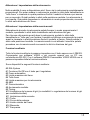
1
Bedienungsanleitung
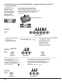
brushless + brushed
Graupner - GENIUS 30 Best.-Nr. 2895
Graupner - GENIUS 40 Best.-Nr. 2896
Graupner - GENIUS 70 Best.-Nr. 2897
GM - GENIUS 80 Best.-Nr. 2894
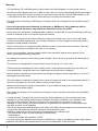
5 Herzlichen Glückwunsch zum Kauf des wohl weltweit besten und vielseitigsten Wettbewerbsregler für
Bürsten- und Bürstenlose Motoren von Graupner/GM-Racing. Dabei können bürstenlose Motoren mit
und ohne Hallsensoren verwendet werden. Wird ein bürstenloser Motor mit Hallsensoren
angeschlossen, so liest der Regler beim ersten Gasgeben nach dem Einstecken die Positionen der
Hallsensoren automatisch ein, so dass danach das noch feinfühligere Regelverhalten verfügbar ist. Bei
unseren Tests war der Regler aber auch ohne Hallsensoren so feinfühlig, dass der Wunsch nach
teureren Motoren mit Sensoren nicht vorhanden war. Mit diesem Regler setzt Entwicklungschef Ralf
Helbing die Reihe seiner erfolgreichen Fahrtenregler fort, mit denen schon zahlreiche Welt- und
Europameisterschaften, sowie nationale Titel gewonnen wurden. Die Genius Regler setzten erneut
Maßstäbe in der Funktionalität und Regelverhalten.
Wichtiger Hinweis:
Bitte lesen Sie diese Anleitung vor Gebrauch Ihres Reglers sorgfältig durch. Nur so nutzen Sie das
gesamte Potential Ihres Reglers und vermeiden Fehler bei der Bedienung.
Beschreibung:
GM-Racing Regler sind mit den neuesten Bauteilen bestückt. Besonderer Wert wird hierbei auf
Funktionalität, Lebensdauer, Stand der Technik, Design und Bauteilgröße gelegt.
Die von unserem Team ständig weiter entwickelte Software garantiert in erster Linie präzise und
einfache Einstellungen. Das „Easy-Set-System” und das „IDA-System“ ermöglicht Ihnen das Einstellen
jeder Funktion innerhalb von Sekunden mit oder ohne Hilfe des GMVIS-Commanders 94401 (Software
V2005 oder neuer) oder mit Hilfe eines PC mit RS-232 Schnittstelle. Mittels weniger Tastendrücke
passen Sie Ihren Regler und damit maßgeblich das Verhalten Ihres Modells den Gegebenheiten an.
Dabei lässt sich der Regler aber auch schon ohne jede Programmierung im Auslieferzustand sofort
einsetzen.
Der Regler ist im Auslieferzustand sowohl für Ni-MH, Ni-Cd als auch für LiPo-Akkus geeignet.
Der Regler erkennt im Modus 1-3 die Spannung des Antriebsakkus nach dem Einstecken des
Fahrakkus automatisch und regelt dann bei Unterschreiten der zulässigen Spannung von 5/8 der
Anfangsspannung die Leistung automatisch ab, um eine Tiefentladung von LiPo-/LiIo-Zellen sowie NiMH und Ni-Cd Zellen zu vermeiden. Vorraussetzung dafür ist ein ausbalancierter Akkupack, bei dem die
Zellen die gleiche Kapazität haben.
Weiterhin erkennt der Regler beim Einstecken automatisch, ob ein Bürstenmotor oder ein Bürstenloser
Motor (mit oder ohne Sensoren) angeschlossen wurde.
Achtung! Bei Verwendung von Bürstenmotoren in der Motorkonfiguration #3 für möglichen
Rückwärtsgang dürfen max. 9,6V Akkus angeschlossen werden.
Programmierbare Hauptfunktionen:
-Modellmodus 1 (vorwärts mit Bremse) Motorsegler, (alle Modelle) mit LiPo-Abschaltung,
Drehzahlbegrenzung bei ca. 180000U/min bei 2Pol-Motoren
-Modellmodus 2 (vorwärts ohne Bremse) Motormodelle, Rennboote mit LiPo-Abschaltung,
Drehzahlbegrenzung bei ca. 120000U/min bei 2Pol-Motoren
-Modellmodus 3 (vorwärst ohne Bremse mit Drehzahlregelung) für Helikopter mit LiPo-Abschaltung
(Dieser Modus ist nur mit bürstenlosen Motoren verwendbar!),
Drehzahlbegrenzung bei ca. 180000U/min bei 2Pol-Motoren
-Modellmodus 4 (vorwärts mit Bremse und rückwärts) für Automodelle, Boote, Trucks mit LiPoAbschaltung für 2 Zellen, Taste als Ein- /Ausschalter.
Drehzahlbegrenzung bei ca. 180000U/min bei 2Pol-Motoren
Genaue Beschreibung der Hauptfunktionen ab Seite 9 und der Zusatzfunktionen siehe ab Seite 15.
Sonstige Funktionen:
- Spannungsüberwachung
- starkes BEC-System
- Digitale Leistungsanpassung im Modellmodus 4
- Wiederaufladen des Fahrakkus beim Bremsen
- rote und grüne LED zur einfachen Programmierung
- Übertemperaturabschaltung
- ...
2
Programmierbare Zusatzfunktionen:
#1 Ein-/Ausschaltfunktion mit Taster für den Regler
#2 Automatikbremse
#3 Bremse Maximum
#4 Vollbremse
#5 Maximale Rückwärtsfahrt
#6 ABS
#7 Automatikgas
#8 Softanlauf
#9 Timing
(nur mit bürstenlosen Motoren)
#10 Drehzahlbegrenzung
(nur mit bürstenlosen Motoren)
(im Modellmodus 3 = Helimodus Drehzahlregelung)
#11 Strombegrenzung
#12 Startstrombegrenzung
#13 Turbo
#14 Powerkurve
#15 Bremse Minimum
#16 Reserviert
#17 Frequenz
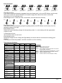
Inhaltsverzeichnis:
Warnhinweise...................................................................................................................... 4
Einbau des Reglers.............................................................................................................. 5
Anschluss des Reglers an den Empfänger.......................................................................... 5
Anschluss eines bürstenlosen Motors (Motorkonfiguration #1)........................................... 6
Anschluss eines Bürstenmotors für die Funktionen vorwärts/Motor aus/(Bremse) (#2)...... 7
Anschluss eines Bürstenmotors für die Funktionen vorwärts/Motor aus/Bremse/rückwärts 8
Einstellen des Reglers auf die Senderwege, Programmierung der Hauptfunktionen......... 9-14
Zurücksetzen der Zusatzfunktionen auf die Werkseinstellung............................................ 9-14
Programmierung des Modellmodus 1 (vorwärts mit Bremse).(Motorsegler)......................... 10
Programmierung des Modellmodus 2 (vorwärts ohne Bremse).(Motormodelle)................... 11
Programmierung des Modellmodus 3 (vorwärts ohne Bremse mit Drehzahlregelung) Heli.. 12-13
Programmierung des Modellmodus 4 (vorwärts mit Bremse und Rückwärtsg.) Auto/Boot... 14
Aktivieren des Rückwärtsgangs/Vorwärtsgangs................................................................... 15
Zusatzfunktionen................................................................................................................... 15-19
Programmieren der Zusatzfunktionen mit dem SET-Taster.................................................. 20-21
IDA-System: Einstellen der Werte mit dem GMVIS-Commander......................................... 22
IDA-System: Einstellen der Werte mit dem PC.................................................................... 23
Programmablauf IDA-System, Zusatzfunktionen................................................................. 24
Fehlermeldungen................................................................................................................. 25
Technische Daten................................................................................................................ 25
Zubehör............................................................................................................................... 25
Kurzanleitung...................................................................................................................... 26-29
Servicestellen...................................................................................................................... 30
3
Warnhinweise:
- Dass CE-Zertifikat des Reglers entbindet nicht der Verpflichtung, äußerste Vorsicht zu wahren.
- Sollte der Motor einmal nicht wie gewünscht anlaufen oder bei einem Absturz stellen Sie den
Senderknüppel sofort auf Motorposition aus, um eine Überlastung des Reglers zu vermeiden. Stellen
Sie die Drehzahlbegrenzung auf 20 = 120000U/min oder niedriger und wählen Sie einen softeren Anlauf
für einen besseren und sauberen Anlauf.
- Benutzen Sie nur Motoren von GM-Racing oder Graupner, die für den verwendeten
Spannungsbereich vorgesehen sind!
- Verwenden Sie nur Hochleistungsakkus von GM-Racing oder Graupner. Akkus mit einem zu
hohen Innenwiderstand können zur Zerstörung des Reglers führen!
- Lassen Sie Ihr RC-Modell niemals unbeaufsichtigt, solange ein Akku angesteckt ist. Im Falle eines
Defektes, könnte dies Feuer am Modell oder seiner Umgebung verursachen.
- Der Fahrtenregler oder andere elektronische Komponenten dürfen niemals mit Wasser in Berührung
kommen. Der Fahrtenregler ist vor Staub, Schmutz, Feuchtigkeit, Vibration und anderen Fremdteilen zu
schützen.
- Solange der Motor an den Regler angeschlossen ist, dürfen Sie niemals den Motor mit einem
separaten Akku laufen lassen. Dies zerstört den Regler und führt zum Verlust der Garantie.
- Verpolen Sie Ihren Regler nicht. Benutzen Sie verpolsichere Stecksysteme. Vermeiden Sie
Kurzschlüsse und blockierende Motoren.
- Alle Kabel und Verbindungen sollen gut isoliert sein. Kurzschlüsse können zur Zerstörung Ihres
Reglers führen.
- Nicht für Kinder unter 14Jahren, kein Spielzeug!
- Die Regler sind ausschließlich für den Einsatz in Batterie- bzw. Akkubetriebenen, funkferngesteuerten
Modellen vorgesehen, ein anderweitiger Betrieb ist nicht zulässig. Der Gebrauch in einem Modell zur
Personenbeförderung ist verboten!
- Motoren, Getriebe, Schiffs- oder Luftschrauben sind gefährliche Gegenstände. Halten Sie sich daher
niemals neben oder vor dem Gefährdungsbereich des Antriebes auf!
- Technische Defekte mechanischer oder elektronischer Teile können zum unverhofften Anlaufen des
Motors und herumfliegenden Teilen führen, die erhebliche Verletzungen verursachen können.
- Führen Sie immer zuerst einen Reichweitetest am Boden durch (halten Sie dabei Ihr Modell fest),
bevor Ihr Modell zum Einsatz kommt.
- Es dürfen keinerlei Veränderungen am Regler durchgeführt werden, es sei denn, diese sind in der
Anleitung beschrieben.
- Haftungsausschluss: Sowohl die Einhaltung der Montage- und Bedienungsanleitung, als auch die
Bedingungen und Methoden bei Installation, Betrieb, Verwendung und Wartung des Fahrtenreglers
können von der Fa. GM-Racing oder Fa. Graupner nicht überwacht werden. Daher übernimmt die Fa.
GM-Racing oder die Fa. Graupner keinerlei Haftung für Verluste, Schäden oder Kosten, die sich aus
fehlerhafter Verwendung und Betrieb ergeben, oder in irgendeiner Weise damit zusammenhängen.
- Es dürfen nur von uns empfohlene Komponenten und Zubehörteile verwendet werden. Verwenden Sie
nur zueinander passende, Original GM-Racing oder GRAUPNER - Steckverbindungen und
Zubehörteile.
- Vergewissern Sie sich vor jeder Inbetriebnahme bevor Sie den Fahrtenregler einstecken, dass: Ihr
Sender als einziger auf der Frequenz Ihres Empfängers sendet und Ihr Sender eingeschaltet ist und der
Gashebel auf der Position STOP steht.
4
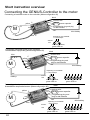
Einbau des Reglers ins Modell:
Nachdem Sie den Regler ausgepackt haben, überlegen Sie sich bitte, an welcher Stelle des Modells
Sie diesen am besten platzieren wollen. Beachten Sie dabei bitte, dass der Regler so gut wie möglich
gekühlt wird und dass der Empfänger sowie die Empfangsantenne möglichst mehr als 3cm Abstand
zum Fahrtenregler, sowie den dicken, stromführenden Kabeln sowie dem Akku haben soll. Nachdem
Sie sich für eine geeignete Stelle entschieden haben, fixieren Sie bitte den Regler so mit zwei Streifen
doppelseitigem Klebeband, dass die Kühlfläche nach oben zeigt und damit gut gekühlt wird oder
höchstens um 30% vermindert wird.
Anschluss des Reglers an den Empfänger:
Ihr Regler ist werkseitig mit einem Graupner/JR-Stecker bestückt. Dieser passt sowohl bei
Graupner/JR- als auch bei Futaba und KO (ab 1995)-Empfängern. Bei anderen Empfängern
erkundigen Sie sich bitte nach der richtigen Polarität.
rot
=
schwarz oder braun=
weiß oder orange =
Empfänger plus
Empfänger minus
Impulsleitung
Stecken Sie den Stecker des Empfängerkabels in den gewünschten Servosteckplatz
(bei Automodellen Steckplatz 2) Ihres Empfängers.
Bevor Sie den Fahrakku anschließen, schalten Sie den Sender ein und stellen den Gashebel auf die
Position „Motor aus“ und schließen Sie den Motor wie anfolgend beschrieben an!
5
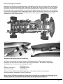
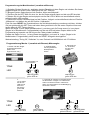
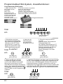
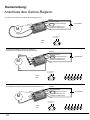
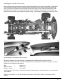
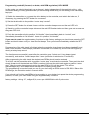
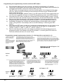
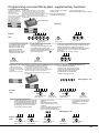
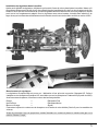
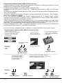
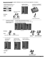
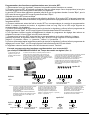
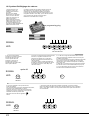
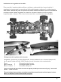
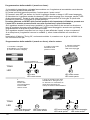
Anschluss eines bürstenlosen Motors (Motorkonfiguration #1):
Benutzen Sie nur Motoren von Graupner oder GM-Racing, die für den verwendeten Spannungsbereich
vorgesehen sind! Motoren anderer Fabrikate könnten zu einem schlechten Anlauf führen und im
schlimmsten Fall den Regler zerstören.
Verbinden/Verlöten Sie die drei Motoranschlüsse des Reglers mit den drei Anschlüssen des Motors.
Sollte Ihr Motor falsch herum laufen, so vertauschen Sie zwei Anschlüsse des Motors. Vertauschen Sie
niemals die Anschlüsse am Akku!
Die Motor- und Akkuanschlusskabel sollten niemals länger als 12cm und möglichst gleich lang sein. Je
länger die Anschlusskabel sind, um so schwerer wird Ihr Modell und um so mehr Störungen strahlen die
Kabel ab.
Bei GM Motoren mit Hallsensoren stecken Sie nun den Stecker der Hallsensoren in den Regler ein.
(rot = 3V, schwarz = GND, andere Farben = Sensoren 1-3). Bei Verwendung eines anderen Fabrikates
kaufen Sie sich das entsprechende Adapterkabel, falls gewünscht.
Ansonsten müssen die Hallsensoren nicht unbedingt angeschlossen sein. Der Motor läuft dann
sensorlos.
Beim ersten Gasgeben nach dem Einschalten des Reglers werden die Positionen der Hallsensoren
automatisch eingelesen, so dass beim 2. Gasgeben der Motor mit Sensoren gestartet wird. Ab einer
bestimmten Drehzahl wird dann automatisch wieder sensorlos kommmutiert um ein besseres Timing
und einen höheren Wirkungsgrad zu erreichen.
Bei angeschlossenen Hallsensoren zeigen die LEDs die Position zweier Hallsensoren an und
funktionieren nicht wie später in der Anleitung beschrieben. Es empfiehlt sich daher zur
Programmierung des Reglers die Hallsensoren vor dem Anschließen der Stromversorgungen
abzustecken.
Anschluss des Akkus:
Verwenden Sie nur Hochleistungsakkus von Graupner oder GM-Racing. Akkus mit einem zu
hohen Innenwiderstand können zur Zerstörung des Reglers führen!
Verbinden Sie das rote Akkuanschlusskabel mit dem Fahrakku +.
Verbinden Sie das schwarze Akkuanschlusskabel mit dem Fahrakku -.
Nach dem Einschalten des Reglers meldet sich der Regler mit dem Modellmodus:
Je nach Modus 1-4
kurze Pieptöne
TÖNE
red gn
rot
LED
...
...
red gn
rot
rote LED blinkt,
grüne LED an
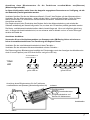
Anschluss eines bürstenlosen Motors (Motorkonfiguration #1)
-
schwarz
Empfängerkabel
M
C
6
B
+
rot
B
A
blau
-
A
Powerkondensator
+
gelb C
Programmierstecker und
Stecker für Hallsensoren
rot
Antriebsakku
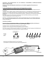
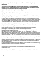
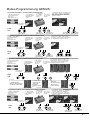
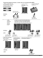
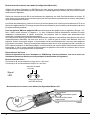
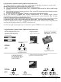
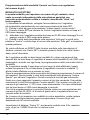
Anschluss eines Bürstenmotors für die Funktionen vorwärts/Motor aus/(Bremse)
(Motorkonfiguration #2):
In dieser Konfiguration steht Ihnen der doppelte angegebene Dauerstrom zur Verfügung, da alle
drei Endstufen parallel geschaltet werden.
Verbinden/Verlöten Sie alle drei Motoranschlüsse A, B und C des Reglers mit dem Motoranschluss -.
Verbinden Sie den Motoranschluss + direkt mit dem Akku + Anschluss des Reglers. Sollte Ihr Motor
falsch herum laufen, so vertauschen die Anschlüsse des Motors. Vertauschen Sie niemals die
Anschlüsse am Akku!
Der Regler erkennt beim Einschalten des Reglers die Art der Motorverkabelung und schaltet die
Software selbständig auf diese Konfiguration um, so dass alle 3 Endstufen parallel geschaltet werden.
Die Motor- und Akkuanschlusskabel sollten dabei niemals länger als 12cm und möglichst gleich lang
sein. Je länger die Anschlusskabel sind, um so schwerer wird Ihr Modell und um so mehr Störungen
strahlen die Kabel ab.
Anschluss des Akkus:
Verwenden Sie nur Hochleistungsakkus von Graupner oder GM-Racing. Akkus mit einem zu
hohen Innenwiderstand können zur Zerstörung des Reglers führen!
Verbinden Sie das rote Akkuanschlusskabel mit dem Fahrakku +.
Verbinden Sie das schwarze Akkuanschlusskabel mit dem Fahrakku -.
Die Erkennung eines Bürstenmotors bestätigt der Fahrtenregler nach dem Anzeigen des Modellmodus
durch 6 kurze Pieptöne (rote LED blinkt 6x kurz und grüne LED an)
Je nach Modus 1-4
kurze Pieptöne
LED
red gn
rot
...
...
red gn
rot
red gn
rot
Anschluss eines Bürstenmotors für die Funktionen
vorwärts/Motor aus/(Bremse) (Motorkonfiguration #2)
M
Powerkondensator
+
rot
B
Programmierstecker und
Stecker für Hallsensoren
rot
Antriebsakku
blau
+
red gn
rot
Empfängerkabel
C
gelb
red gn
rot
+
A, B, C
red gn
rot
schwarz
-
blau
red gn
rot
rote LED blinkt 6x,
grüne LED an
rote LED blinkt,
grüne LED an
-
red gn
rot
-
TÖNE
A
rot
Akku+
7
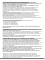
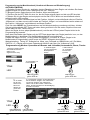
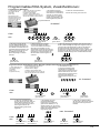
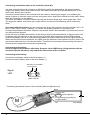
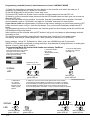
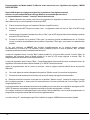
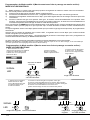
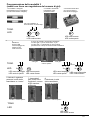
Anschluss eines Bürstenmotors für die Funktionen vorwärts/Motor aus/Bremse/rückwärts
(Motorkonfiguration #3):
Achtung! In dieser Konfiguration steht Ihnen nur der halbe angegebene Dauerstrom zur
Verfügung.
In dieser Konfiguration nur Akkus mit max. 9,6V angeschlossen werden!
Verbinden/Verlöten Sie den äußeren blauen Motoranschluss A des Reglers mit dem Motoranschluss des Motors.
Verbinden Sie den gelben (anderen äußeren) Motoranschluss C des Reglers mit dem Motoranschluss +
des Motors. Der mittlere Motoranschluss des Reglers bleibt unbenutzt.(frei) Sollte Ihr Motor falsch
herum laufen, so vertauschen Sie die Anschlüsse des Motors. Vertauschen Sie niemals die Anschlüsse
am Akku!
Der Regler erkennt beim Einschalten des Reglers die Art der Motorverkabelung und schaltet die
Software selbständig auf diese Konfiguration um.
Die Motor- und Akkuanschlusskabel sollten dabei niemals länger als 12cm und möglichst gleich lang
sein. Je länger die Anschlusskabel sind, um so schwerer wird Ihr Modell und um so mehr Störungen
strahlen die Kabel ab.
Anschluss des Akkus:
Verwenden Sie nur Hochleistungsakkus von Graupner oder GM-Racing. Akkus mit einem zu
hohen Innenwiderstand können zur Zerstörung des Reglers führen!
Verbinden Sie das rote Akkuanschlusskabel mit dem Fahrakku +.
Verbinden Sie das schwarze Akkuanschlusskabel mit dem Fahrakku -.
Die Erkennung eines Bürstenmotors bestätigt der Fahrtenregler nach dem Anzeigen des Modellmodus
durch 6 kurze Pieptöne (rote LED blinkt 6x kurz und grüne LED an)
Je nach Modus 1-4
kurze Pieptöne
TÖNE
LED
red gn
rot
...
...
red gn
rot
red gn
rot
red gn
rot
red gn
rot
red gn
rot
red gn
rot
red gn
rot
rote LED blinkt 6x,
grüne LED an
rote LED blinkt,
grüne LED an
Anschluss eines Bürstenmotors für die Funktionen
vorwärts/Motor aus/Bremse/rückwärts (Motorkonfiguration #3)
schwarz
-
Powerkondensator
+
M
-
8
A
rot
B
Programmierstecker und
Stecker für Hallsensoren
rot
A
blau
-
C
+
+
Empfängerkabel
gelb C
Antriebsakku
Einstellung des Reglers auf die Senderwege, Programmierung der Hauptfunktionen,
Zurücksetzen der Zusatzfunktionen auf die Werkseinstellungen:
Damit der Regler richtig funktionieren kann stellen Sie bitte alle Funktionen des Gashebels auf
“NORMAL” (Futaba “REVERSE”) und die Wege auf 100%.
Der Regler benutzt den Motor als Lautsprecher für die Pieptöne. Deshalb können Sie die
Pieptöne nur bei angeschlossenem Motor hören.
Bei angeschlossenen Hallsensoren zeigen die LEDs die Position zweier Hallsensoren an und
funktionieren nicht wie später in der Anleitung beschrieben. Es empfiehlt sich daher zur
Programmierung des Reglers die Hallsensoren vor dem Anschließen der Stromversorgungen
abzustecken. Geübte Programmierer können den Regler aber auch nur mit Hilfe der Pieptöne
programmieren.
Der Regler hat voreingestellte Knüppelwege. Die Werkseinstellung ist auf den Modellmodus 1
(vorwärts mit Bremse), geeignet für alle Modelle mit LiPo-Abschaltung eingestellt.
Mit diesem Modus lassen sich erst einmal alle Modelle mit allen Akkusorten betreiben.
Damit der Motor aktiviert wird, muss zuerst der Senderhebel auf die Position „Motor aus oder
Bremse“ gebracht werden. Ansonsten läuft der Motor aus Sicherheitsgründen nicht an.
Sollte der Motor in der Gasstellung bremsen und in der Bremsstellung anlaufen, dann programmieren
Sie bitte den Senderknüppel auf „Reverse“ (Futaba)!
Bei richtiger Einstellung der Senderwege leuchtet:
- die rote und die grüne LED in der Knüppelposition „Motor aus/Neutralstellung“
- die grüne LED im „Gasregelbereich“
- die rote LED in der „Vollgasstellung“
- keine LED in dem „Bremsregelbereich“
- die rote LED in der „Vollbremsestellung“
Einstellung des Reglers auf die genauen Senderwege und Einstellung der Hauptfunktionen
(Modellmodus 1-4):
Im Modellmodus 1-3 wird nach dem Einschalten des Reglers die Akkuspannung gemessen und
die Unterspannungsabschaltung so berechnet, dass diese sowohl für LiPo-Akkus als auch für
Ni-MH und Ni-Cd Akkus optimal geeignet ist.
Wenn sich der Regler einschaltet, gibt er je nach gewähltem Modellmodus 1-3 kurze Pieptöne aus und
die rote LED blinkt dabei, um den Modellmodus und das Einschalten des Reglers zu bestätigen.
Bei angeschlossenem Bürstenmotor piepst der Regler nach einer kurzen Pause noch einmal 6x kurz
und die rote LED blinkt dabei.
Der Regler ist nach dem Einstecken an den Antriebsakkus sofort an und aktiviert, wenn der
Senderknüppel auf „Motor aus“ oder „Bremse steht“.
Im Modellmodus 4 wird der Motor bei einer Akkuspannung unter 4V abgeregelt. Damit erreichen
Sie die max. Beschleunigung, ohne dass der Empfänger Störungen bekommt.
Der Regler lässt sich über die SET-Taste ein- oder ausschalten. Er lässt sich ebenfalls
ausschalten, wenn man am Sender ca. 16s lang den Gashebel auf der Position „Vollbremse“
hält. Dadurch kann der Regler ausgeschaltet werden, ohne den Fahrerstand zu verlassen.
Wenn sich der Regler einschaltet, gibt er je nach gewähltem Modellmodus 4 kurze Pieptöne aus und die
rote LED blinkt dabei, um den Modellmodus zu und das Einschalten des Reglers zu bestätigen.
Bei angeschlossenem Bürstenmotor piepst der Regler nach einer kurzen Pause noch einmal 6x kurz
und die rote LED blinkt dabei.
Der Regler ist nach dem Einstecken an den Antriebsakkus erst nach einem Tastendruck an und
aktiviert, wenn der Senderknüppel auf „Motor aus“ oder „Bremse steht“.
Wurde der Regler nicht abgeschaltet, so ist er beim nächsten Anstecken an den Fahrakku sofort
an.
Der Softanlauf ist auf 68ms von kein Gas bis Vollgas programmiert. Timing 30°
In diesem Modus dürfen Ni-MH und Ni-Cd Akkus ohne Beschränkung oder LiPo-Akkus mit 2
Zellen verwendet werden.
-Modellmodus 1 (vorwärts mit Bremse) Motorsegler, (alle Modelle) mit LiPo-Abschaltung
-Modellmodus 2 (vorwärts ohne Bremse) Motormodelle, Rennboote mit LiPo-Abschaltung
-Modellmodus 3 (vorwärst ohne Bremse mit Drehzahlregelung) für Helikopter mit LiPo-Abschaltung
-Modellmodus 4 (vorwärts mit Bremse und rückwärts) für Automodelle, Boote, Trucks ohne LiPoZellenzahlerkennung, Taste als Ein- /Ausschalter.
9
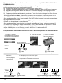
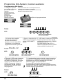
Programmierung des Modellmodus 1 (vorwärts mit Bremse):
1.) Schalten Sie den Sender ein, verbinden sie den Fahrakku mit dem Regler und schalten Sie diesen
gegebenenfalls mit einem kurzen Tastendruck der SET-Taste ein.
2.) Bringen Sie den Gasknüppel auf die Position „Motor aus/Nullpunkt“.
3.) Drücken Sie die SET-Taste für mind. 4s, bis der Regler einmal piepst und die rote LED leuchtet.
4.) Warten Sie, bis der Regler zweimal piepst und die rote LED 2x blinkt und anschließend erlischt,
sowie die grüne LED leuchtet.
5.) Gehen Sie mit dem Senderknüppel auf die Position „Vollgas“ und anschließend sofort auf Position
„Vollbremse“ und bleiben sie auf der Position „Vollbremse“.
Falls Sie einen RESET der Zusatzfunktionen auf die Werkseinstellung vornehmen möchten, drücken
Sie jetzt gleichzeitig die SET-Taste und halten diese gedrückt bis Sie die ersten Pieptöne hören und
lassen dann die SET-Taste sofort los.
Wenn der Regler 1x kurz piepst (Modellmodus 1) und dann nach 2s Pause erneut 1x kurz piepst
(Regler ist im Modellmodus 1 eingeschaltet) und die rote LED bei jedem Piepton blinkt ist die
Programmierung beendet und Sie können den Taster wieder loslassen.
Piepste der Regler 3x kurz, 1 x lang (Reset durchgeführt), und nach 3s 1x kurz (Regler ist im
Modellmodus 1 eingeschaltet), dann wurde ein RESET erfolgreich durchgeführt.
Werkseinstellung: Timing 30°, Softanlauf 1s, max. Drehzahl ca.180000U/min mit 2 Pol-Motor
Programmierung Modus 1 (vorwärts mit Bremse) Motorsegler:
3. SET-Taste für
ca. 4s drücken,
bis rote LED
leuchtet
2. Senderknüppel
auf die gewünschte
Neutralposition
stellen
1. Sender und dann Regler
einschalten/einstecken
(Motor muss
angeschlossen sein)
Je nach Modus 1-4
kurze Pieptöne
TÖNE
LED
red gn
rot
...
...
“Neutral=Motor aus”
red gn
rot
red gn
rot
rote LED blinkt,
grüne LED an
rote LED an,
grüne LED aus
5. innerhalb der nächsten 4s Senderknüppel
auf die Position “Vollgas” und “Vollbremse”
stellen und auf der Position “Vollbremse”
halten, bis die Piepstöne für die Bestätigung
für Modus 1 ertönen.
4.
ca. 2s warten,
bis die rote
LED 2x kurz
blinkt und
danach die
grüne LED
leuchtet
“Vollgas”
TÖNE
LED
1s
Pause
2x
red gn
rot
rote LED blinkt,
grüne LED aus
10
“Vollbremse”
red gn
rot
rote LED aus,
grüne LED an
red gn
rot
rote LED blinkt,
grüne LED aus
red gn
rot
rote LED blinkt,
grüne LED an
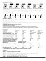
Programmierung des Modellmodus 2 (vorwärts ohne Bremse):
1.) Schalten Sie den Sender ein, verbinden sie den Fahrakku mit dem Regler und schalten Sie diesen
gegebenenfalls mit einem kurzen Tastendruck der SET-Taste ein.
2.) Bringen Sie den Gasknüppel auf die Position „Motor aus/Nullpunkt“.
3.) Drücken Sie die SET-Taste für mind. 4s, bis der Regler einmal piepst und die rote LED leuchtet.
4.) Warten Sie, bis der Regler zweimal piepst und die rote LED 2x blinkt und anschließend erlischt,
sowie die grüne LED leuchtet.
5.) Gehen Sie mit dem Senderknüppel auf die Position „Vollgas“ und bleiben sie auf dieser Position.
Falls Sie einen RESET der Zusatzfunktionen auf die Werkseinstellung vornehmen möchten, drücken
Sie jetzt gleichzeitig die SET-Taste und halten diese gedrückt bis Sie die ersten Pieptöne hören und
lassen dann die SET-Taste sofort los.
Wenn der Regler 2x kurz piepst (Modellmodus 2) und dann nach 2s Pause erneut 2x kurz piepst
(Regler ist im Modellmodus 2 eingeschaltet) und die rote LED bei jedem Piepton blinkt ist die
Programmierung beendet.
Piepste der Regler 3x kurz, 1 x lang (Reset durchgeführt), und nach 3s 2x kurz (Regler ist im
Modellmodus 2 eingeschaltet), dann wurde ein RESET erfolgreich durchgeführt.
Werkseinstellung: Timing 30°, Softanlauf 1s, max. Drehzahl ca.120000U/min mit 2 Pol-Motor
Programmierung Modus 2 (vorwärts ohne Bremse) Motormodelle:
3. SET-Taste für
ca. 4s drücken,
bis rote LED
leuchtet
2. Senderknüppel
auf die gewünschte
Neutralposition
stellen
1. Sender und dann Regler
einschalten/einstecken
(Motor muss
angeschlossen sein)
Je nach Modus 1-4
kurze Pieptöne
TÖNE
LED
red gn
rot
...
...
“Neutral=Motor aus”
red gn
rot
red gn
rot
rote LED blinkt,
grüne LED an
rote LED an,
grüne LED aus
5. innerhalb der nächsten 4s Senderknüppel
auf die Position “Vollgas” stellen und auf der
Position “Vollgas” halten, bis die Piepstöne
für die Bestätigung für Modus 2 ertönen.
4.
ca. 2s warten,
bis die rote
LED 2x kurz
blinkt und
danach die
grüne LED
leuchtet
“Vollgas”
TÖNE
LED
1s
Pause
2x
red gn
rot
rote LED blinkt,
grüne LED aus
red gn
rot
rote LED aus,
grüne LED an
red gn
rot
red gn
rot
rote LED blinkt,
grüne LED aus
red gn
rot
red gn
rot
rote LED blinkt,
grüne LED an
11
Programmierung des Modellmodus 3 (vorwärts ohne Bremse mit Drehzahlregelung):
HELIMODUS
Verwenden Sie in diesem Modus für die Einstellung der geregelten (= konstant gehaltenen)
Drehzahl einen von der Gas-/Pitchmischung unabhängigen Kanal mit daran angeschlossenen
Schiebe- oder Drehpoti in folgendem Text mit Geber bezeichnet.
1.) Schalten Sie den Sender ein, verbinden sie den Fahrakku mit dem Regler und schalten Sie diesen
gegebenenfalls mit einem kurzen Tastendruck der SET-Taste ein.
2.) Bringen Sie den Geber (Schiebe- oder Drehpoti) auf die Position „Motor aus“.
3.) Drücken Sie die SET-Taste für mind. 4s, bis der Regler einmal piepst und die rote LED leuchtet.
4.) Warten Sie, bis der Regler zweimal piepst und die rote LED 2x blinkt und anschließend erlischt,
sowie die grüne LED leuchtet.
5.) Gehen Sie mit dem Geber auf die Position „max. Drehzahl“ und anschließend sofort auf Position
„Motor aus“ und dann sofort wieder auf die Position „max. Drehzahl“ und bleiben sie auf dieser Position.
Falls Sie einen RESET der Zusatzfunktionen auf die Werkseinstellung vornehmen möchten, drücken
Sie jetzt gleichzeitig die SET-Taste und halten diese gedrückt bis Sie die ersten Pieptöne hören und
lassen dann die SET-Taste sofort los.
Wenn der Regler 3x kurz piepst (Modellmodus 3) und dann nach 2s Pause erneut 3x kurz piepst
(Regler ist im Modellmodus 3 eingeschaltet) und die rote LED bei jedem Piepton blinkt ist die
Programmierung der Geberwege beendet.
Piepste der Regler 3x kurz, 1 x lang (Reset durchgeführt), und nach 3s 3x kurz (Regler ist im
Modellmodus 3 eingeschaltet), dann wurde ein RESET erfolgreich durchgeführt.
Nach der Programmierung der Geberwege muss nun noch die Programmierung der gewünschten
maximalen Drehzahl vorgenommen werden.
Dazu gehen sie nun mit dem Geber auf die Position „Motor aus“, um den Regler zu aktivieren.
Danach betätigen Sie den Geber langsam soweit, bis die maximale gewünschte Drehzahl erreicht wird.
Nun bringen Sie den Geber wieder auf die Position „Motor aus“. Wenn der Motor nicht mehr läuft wird
die maximale Drehzahl +- etwa 10% abgespeichert. Dies wird durch 3 kurze Piepstöne (rote LED blinkt
dabei 3x) bestätigt.
Nun ist die Programmierung abgeschlossen und Sie können mit einer Drehzahlregelung von 50-100%
fliegen. Unterhalb dieses Bereiches arbeitet der Regler im Stellerbetrieb.
Sollte sich herausstellen, dass die maximale Drehzahl nicht Ihren Wünschen entspricht, so nehmen Sie
die Programmierung einfach erneut durch oder programmieren die gewünschte maximale Drehzahl
über die Zusatzfunktionen.
Es kann hilfreich sein, nach dem Einlernen der Geberwege und der Drehzahl eine Zeitverzögerung für
den Geber zu programmieren, um einen sanfteren Anlauf zu erreichen. Während der Programmierung
des Reglers darf jedoch keine Zeitverzögerung eingestellt sein.
(Falls Sie das Gas mit PITCH mischen möchten verwenden Sie bitte den Modellmodus 2
(vorwärts/Motor aus)!)
Werkseinstellung: Timing 15°, Softanlauf ca. 0,2s, max. Drehzahl ca.180000U/min mit 2 Pol-Motor
12
Programmierung Modus 3 (vorwärts mit Drehzahlregelung) Heli:
3. SET-Taste für
ca. 4s drücken,
bis rote LED
leuchtet
2. Geber auf die
Position “Motor aus”
stellen
1. Sender und dann Regler
einschalten/einstecken
(Motor muss
angeschlossen sein)
Je nach Modus 1-4
kurze Pieptöne
TÖNE
LED
red gn
rot
...
...
“Neutral=Motor aus”
red gn
rot
red gn
rot
rote LED blinkt,
grüne LED an
5. innerhalb der nächsten 4s Geber auf die
Position “max. Drehzahl” und “Motor aus” und
wieder “max. Drehzahl” stellen und auf der Position
“max. Drehzahl” halten, bis die Piepstöne für die
Bestätigung für Modus 3 ertönen.
4.
ca. 2s warten,
bis die rote
LED 2x kurz
blinkt und
danach die
grüne LED
leuchtet
“max. Drehzahl” “Neutral=Motor aus” “max. Drehzahl”
TÖNE
LED
rote LED an,
grüne LED aus
2x
red gn
rot
red gn
rot
3x
rote LED blinkt, rote LED aus,
grüne LED aus grüne LED an
6. Regler aktivieren,
indem der Geber auf
“Motor aus” gestellt
wird.
7. Geben Sie so
viel Gas, bis die
gewünschte
maximale Drehzahl
erreicht ist.
LED
red gn
rot
rote LED blinkt,
grüne LED aus
3x
red gn
rot
rote LED blinkt,
grüne LED an
8. Stellen Sie den
Geber wieder auf
die Position
“Motor aus”
“Neutral=Motor aus”
“Neutral=Motor aus”
TÖNE
1s
Pause
“Gas bis zur´
gewünschten
Drehzahl”
3x
red gn
rot
rote LED blinkt,
grüne LED an
13
Programmierung des Modellmodus 4 ( Vorwärts mit Bremse und Rückwärtsgang)
AUTO/BOOTMODUS)
1.) Schalten Sie den Sender ein, verbinden sie den Fahrakku mit dem Regler und schalten Sie diesen
gegebenenfalls mit einem kurzen Tastendruck der SET-Taste ein.
2.) Bringen Sie den Gasknüppel auf die Position „Motor aus/Nullpunkt“.
3.) Drücken Sie die SET-Taste für mind. 4s, bis der Regler einmal piepst und die rote LED leuchtet.
4.) Warten Sie, bis der Regler zweimal piepst und die rote LED 2x blinkt und anschließend erlischt,
sowie die grüne LED leuchtet.
5.) Gehen Sie mit dem Senderknüppel auf die Position „Vollgas“ und anschließend sofort auf Position
„Vollbremse“ und dann erneut sofort wieder auf Position „Vollgas“ und anschließend sofort wieder auf
die Position „Vollbremse“ und bleiben sie auf dieser Position.
Falls Sie einen RESET der Zusatzfunktionen auf die Werkseinstellung vornehmen möchten, drücken
Sie jetzt gleichzeitig die SET-Taste und halten diese gedrückt bis Sie die ersten Pieptöne hören und
lassen dann die SET-Taste sofort los.
Wenn der Regler 4x kurz piepst (Modellmodus 4) und die rote LED bei jedem Piepton blinkt ist die
Programmierung beendet.
Nach dem Einschalten des Reglers mit der SET-Taste piepst dann der Regler jeweils 4x kurz, um den
Modellmodus 4 zu bestätigen und die Betriebsbereitschaft zu signalisieren.
Piepste der Regler 3x kurz, 1 x lang (Reset durchgeführt), und nach 3s 4x kurz (Regler ist im
Modellmodus 4 eingeschaltet), dann wurde ein RESET erfolgreich durchgeführt.
Werkseinstellung: Timing 30°, Softanlauf ca. 68ms, max. Drehzahl ca.180000U/min mit 2 Pol-Motor,
SWITCH = 5 = Regler nach kurzem Tastendruck AN/AUS oder über 16s “Vollbremse” AUS.
Programmierung Modus 4 (vorwärts mit Bremse und rückwärts) Automodelle, Boote, Trucks:
2. Senderknüppel
auf die gewünschte
Neutralposition
stellen
1. Sender und dann Regler
einschalten/einstecken
(Motor muss
angeschlossen sein)
3. SET-Taste für
ca. 4s drücken,
bis rote LED
leuchtet
Je nach Modus 1-4
kurze Pieptöne
TÖNE
LED
red gn
rot
...
...
“Neutral=Motor aus”
red gn
rot
red gn
rot
rote LED blinkt,
grüne LED an
4.
ca. 2s warten,
bis die rote
LED 2x kurz
blinkt und
danach die
grüne LED
leuchtet
rote LED an,
grüne LED aus
5. innerhalb der nächsten 4s Senderknüppel
auf die Position “Vollgas” und “Vollbremse”
und erneut “Vollgas” und “Vollbremse”
stellen und auf der Position “Vollbremse”
halten, bis die Piepstöne für die Bestätigung
für Modus 4 ertönen.
“Vollgas”
“Vollbremse”
“Vollgas”
“Vollbremse”
TÖNE
LED
2x
1s
Pause
red gn
rot
red gn
rot
rote LED blinkt, rote LED aus,
grüne LED aus grüne LED an
14
4x
red gn
rot
rote LED blinkt,
grüne LED aus
4x
red gn
rot
rote LED blinkt,
grüne LED an
Aktivieren/Einlegen des Rückwärtsgangs
Im Modellmodus 4 haben Sie sowohl eine voll proportionale Bremse als auch einen voll proportionalen
Rückwärtsgang. Um rückwärts fahren zu können gehen Sie mit dem Senderknüppel auf die Position
„Vollbremse“ und bleiben dort, bis das Fahrzeug steht und dann noch für etwa 1s länger. Danach
bringen Sie den Senderknüppel in die „Neutralstellung/Nullpunkt“. Der Rückwärtsgang ist nun eingelegt.
Sie können nun proportional rückwärts fahren, in dem Sie den Senderknüppel in Bremsrichtung
bewegen.
Aktivieren/Einlegen des Vorwärtsgangs
Natürlich können Sie auch bei der Rückwärtsfahrt das Fahrzeug proportional abbremsen, indem Sie
den Senderknüppel in Gasrichtung bewegen.
Um nach der Rückwärtsfahrt wieder vorwärts fahren zu können gehen Sie mit dem Senderknüppel auf
die Position „Vollgas“ um das Fahrzeug abzubremsen und den Vorwärtsgang wieder aktivieren zu
können und bleiben dort, bis das Fahrzeug steht. Danach bringen Sie den Senderknüppel in die
„Neutralstellung/Nullpunkt“. Der Vorwärtsgang ist nun wieder aktiviert/eingelegt. Sie können nun wieder
vorwärts fahren, in dem Sie den Senderknüppel in Gasrichtung bewegen.
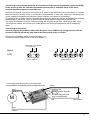
Zusatzfunktionen:
Alle Zusatzfunktionen lassen sich über die Taste oder über den GMVIS Commander mit Software
V2005 oder neuer oder mit einem PC mit RS-232 Schnittstelle einstellen. Mit der GMVIS - Commander
Software V2001-V2004 lassen sich nicht alle Funktionen einstellen.
Folgende Zusatzfunktionen sind verfügbar:
#0 IDA-System
#1 Ein-/Ausschaltfunktion mit Taster für den Regler
#2 Automatikbremse
#3 Bremse Maximum
#4 Vollbremse
#5 Maximale Rückwärtsfahrt
#6 ABS
#7 Automatikgas
#8 Softanlauf
#9 Timing
#10 Drehzahlbegrenzung (im Modellmodus 4 = Helimodus Drehzahlregelung)
#11 Strombegrenzung
#12 Startstrombegrenzung
#13 Turbo
#14 Powerkurve
#15 Bremse Minimum
#16 Reserviert
#17 Frequenz
15
#1
Ein- /Ausschaltfunktion mit Taster für den Regler
REGLER EIN/AUS (0,1,2,4,5,6)
Der Regler kann so programmiert werden, dass er sich samt dem BEC-System über die SET-Taste Einund Ausschalten lässt. Außerdem kann er so programmiert werden, dass er auch über den Sender
ausgeschaltet werden kann, indem man mindestens 16s auf die Position „Vollbremse“ geht.
Wenn sich der Regler einschaltet, gibt er je nach gewähltem Modellmodus 1-4 kurze Pieptöne aus und
die rote LED blinkt dabei (grüne LED an), um den Modellmodus zu und das Einschalten des Reglers zu
bestätigen. Bei Anschluss eines Bürstenmotors gibt der Regler nach einer kurzen Pause weitere 6
kurze Pieptöne aus, die rote LED blinkt dabei und die grüne LED ist dabei an.
0 = Regler immer an (Werkseinstellung im Modellmodus 1-3)
1 = Regler nach kurzem Tastendruck an und nach erneutem kurzen Tastendruck aus
2 = Regler nach einstecken des Fahrakkus sofort an, aber mit kurzem Tastendruck aus-/ einschaltbar.
Danach wieder über Taste einschaltbar.
4 = Regler nach 16s Vollbremse aus oder kurzen Tastendruck aus
5 = Regler nach kurzem Tastendruck an, nach 16s Vollbremse oder kurzem Tastendruck ausschaltbar
(Werkseinstellung im Modellmodus 4)
6 = Regler nach einstecken des Fahrakkus sofort an, aber mit kurzem Tastendruck oder nach 16s
Vollbremse aus. Danach wieder über Taste einschaltbar
#2
AUTOMATIKBREMSE (AUTOBRAKE)
Die Automatikbremse ist von 0-100% einstellbar und wirkt bereits bei Neutralstellung des Gashebels.
Sie ist unabhängig von der minimalen und maximalen Bremswirkung einstellbar und erlaubt daher ein
engeres Kurvenfahren.
Werkseinstellung: 0%, empfohlene Werte 0 - 30%
#3
MAXIMALE BREMSE (BRAKEMAX)
Die maximale Bremswirkung ist die, die kurz vor leuchten der roten LED ansteht. Mit dieser Funktion
lässt sich ein Überbremsen/Blockieren der Räder verhindern.
Die maximale Bremswirkung im Regelbereich ist von 0-100% einstellbar.
Nach dem Programmieren der maximalen Bremse mit der SET-Taste, wird der VOLLBREMSE -Wert mit
dem maximalen Bremswert gleich gesetzt, damit ein unerwünschtes Überbremsen auch im
Vollbremsebereich (rote LED an) verhindert wird. Wird für den Vollbremse-Wert ein anderer Wert
gewünscht, so kann dieser nur nach dem Maximalen Bremswert oder mit dem GMVIS-Commander
programmiert werden.
Werkseinstellung: 100%, empfohlene Werte für Autos 70-80%
#4
VOLLBREMSE (FULLBRAKE)
Die Bremswirkung in der Gashebelposition „Vollbremse“ lässt sich getrennt von der maximalen Bremse
einstellen. Dies ist besonders im Off-Road gewünscht, wo in den Kurven ein guter Bremsregelbereich
gewünscht wird, bei Sprüngen für die Flugbahnkorrektur jedoch die volle Bremswirkung benötigt wird.
Weiterhin ist diese Funktion für eine „Notbremse“ sinnvoll.
Die „Vollbremse“ - Funktion muss nach der maximalen Bremse oder mit dem GMVIS-Commander
programmiert werden, ansonsten ist der maximale Bremswert auch der Vollbremse - Wert.
Die „Vollbremse“ Funktion ist ebenfalls von 0-100% einstellbar.
Werkseinstellung: 100%, empfohlene Werte 70-100%
#5
MAXIMALE RÜCKWÄRTSFAHRT (MAXREVERSE)
Die Maximale Rückwärtsfahrt lässt sich zwischen 0 100% einstellen. Damit lässt sich in Rennbooten
oder auch für RC Cars die maximale Rückwärtsfahrt begrenzen.
Werkseinstellung 100%, empfohlene Werte für Rennboote 20-50%, Autos 50-100%
16
#6
ABS (0=AUS, 1=EIN)
Die ABS Bremse verhindert das Ausbrechen des Fahrzeuges beim Bremsen. Die ABS-Bremse taktet
zwischen vom Gashebel vorgegebenen max. Bremswert und dem BRKMIN Wert.
Werkseinstellung: 0 = AUS,
Empfohlene Einstellungen: 1= EIN, BRAKEMIN 20-40%, BRAKEMAX 70-100%
#7
AUTOGAS (0-9)
„Standgas“ in der Senderposition „Neutralstellung/Nullpunkt“, ist besonders in Standardklassen sinnvoll,
wo ein besseres rollen des Fahrzeuges erwünscht ist.
Nach einigen Sekunden wird das „AUTOGAS“ deaktiviert, um am Start einen Frühstart durch ein
losrollendes Fahrzeug zu vermeiden und um bei längeren Standzeiten Strom zu sparen.
Damit das AUTOGAS funktioniert, muss die AUTOMATIKBREMSE auf 0% eingestellt sein!
0 = Werkseinstellung, empfohlen Einstellungen für Standardklassen 1 = 4% - 5 = 20%
#8
SOFTANLAUF (0 - 10 mit SET-Taste, mit GMVIS - Commander 0 - 200)
Je kleiner der eingestellte Wert, um so sanfter schaltet der Regler durch.
Sollte Ihr Motor nicht wie gewünscht anlaufen, oder in einer bestimmten Drehzahl zu früh „hängen
bleiben“, dann schalten Sie den Motor sofort wieder aus und reduzieren Sie den Wert (bzw. erhöhen Sie
die Hochlaufzeit), bis der Motor sauber anläuft und hochdreht. Mit den Werkseinstellung laufen in der
Regel alle Motoren sauber an.
0 = Hochlaufzeit 2s
1 = Hochlaufzeit 1s (Werkseinstellung in Modellmodus 1-3)
2 = Hochlaufzeit 0,7s
3 = Hochlaufzeit 0,5s
4 = Hochlaufzeit 0,4s
5 = Hochlaufzeit 0,34s
6 = Hochlaufzeit 0,3s
7 = Hochlaufzeit 0,25s
8 = Hochlaufzeit 0,22s
9 = Hochlaufzeit 0,2s
10 = mit GMVIS - Commander = Hochlaufzeit 0,18s, bei SET - Taste = 30 = Hochlaufzeit 68ms
(Werkseinstellung im Modellmodus 4 = 68ms)
nur mit GMVIS Commander:
...
20 = Hochlaufzeit 0,1s
...
30 = Hochlaufzeit 68ms
...
50 = Hochlaufzeit 40ms
...
100 = Hochlaufzeit 20ms
...
200 = Hochlaufzeit 10ms
#9
TIMING (0-4) (nur mit bürstenlosen Motoren!)
Um den maximalen Wirkungsgrad zu erreichen, kann das Timing eingestellt werden.
In den meisten Fällen hat die Werkseinstellung den besten Wirkungsgrad.
Bei problematischen Motoranlauf empfiehlt es sich 30° Timing zu wählen.
0 = 0° Timing
1 = 7,5° Timing
2 = 15° Timing
4 = 30° Timing
(Werkseinstellung im Modus 3)
(Werkseinstellung im Modus 1-2, 4)
17
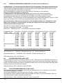
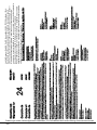
#10
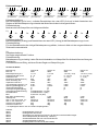
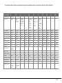
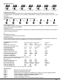
DREHZAHLBEGRENZUNG (RPMLIMIT) (nur mit bürstenlosen Motoren!)
Im Modellmodus 1,2 und 4 lässt sich die maximale Drehzahl begrenzen. Dies eignet sich besonders für
Standardklassen um eine Einheitliche Drehzahl mit einer vorgeschriebenen Getriebeuntersetzung und
damit die gleiche Endgeschwindigkeit zu erreichen oder um bei Flugmodellen die Drehzahl auf eine
maximale Drehzahl der Luftschraube zu begrenzen.
Die Drehzahlbegrenzung eignet sich auch besonders für Einsteiger um die maximale
Endgeschwindigkeit des Modells zu begrenzen.
Im Modellmodus 3 (Helimodus) lässt sich die Drehzahl zwischen der halben eingestellten
Drehzahlbegrenzung und der eingestellten Drehzahlbegrenzung regeln. Unterhalb der halben
eingestellten Drehzahl lässt sich der Regler wie ein Regler ohne Drehzahlregelung regeln.
Mit dem GMVIS - Commander kann die Drehzahlbegrenzung bei zweipoligen Motoren zwischen 12 500
U/min und 210 000 U/min in 200 Stufen eingestellt werden, siehe Formel, Grafik!
Bei problematischen Motoranlauf empfiehlt es sich die Motordrehzahl auf 120000U/min (2-Pol
Motor) oder niedriger zu programmieren, da dann der Regler durch eine andere Software für
einen besseren Anlauf sorgen kann!
Bei mehr als 2-poligen Motoren entspricht die Drehzahl:
Drehzahl = angegebene Drehzahl * 2 / Polzahl
Mit der SET - Taste lassen sich 11 verschiedene Drehzahlen einstellen.
Eingestellter Wert 2-Pol Motor 4-Pol-Motor
mit SET - Taste
ca. U/min ca. U/min
0 (Werkseinstellung) 210 000 105 000
1
160 000 80 000
2
120 000 60 000
3
90 000
45 000
4
70 000
35 000
5
50 000
25 000
6
40 000
20 000
7
30 000
15 000
8(ROAR-Sportsman) 24 000 12 000
9
17 500
8 750
10
12 500
6 250
8-Pol Motor
ca. U/min
52 000
40 000
30 000
22 500
17 500
12 500
10 000
7 500
6 000
4 375
3 125
10-Pol Motor 14-Pol Motor 16-Pol Motor
ca. U/min
ca. U/min
ca. U/min
42 000
30 000
26 000
32 000
23 000
20 000
24 000
17 000
15 000
18 000
13 000
11 250
14 000
10 000
8 750
10 000
7 000
6 250
8 000
5 700
5 000
6 000
4 300
3 750
4 800
3 400
3 000
3 500
2 500
2 200
2 500
1 800
1 500
Formeln für die maximale Drehzahl (U/min) bei Einstellung mit dem GMVIS-Commander:
max. Drehzahl ca. = 5 000 000 / {(Eingestellter Wert +12 * Polzahl des Motors}
eingestellter Wert ca. = {5 000 000 / (max. Drehzahl * Polzahl des Motors)} - 12
ROAR-Sportsman = 92 = 24 000U/min
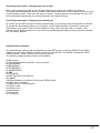
#11
STROMBEGRENZUNG (AMP LIMIT)
Die Strombegrenzung kann mit Hilfe des Tasters von 50 - 150A oder mit dem GMVIS-Commander von
0-200A eingestellt werden. Durch die Strombegrenzung kann das Drehmoment des Motors beeinflusst
werden. Die Strombegrenzung sollte so eingestellt werden, dass z. B. beim Automodell die Räder beim
Anfahren nicht oder nur leicht durchdrehen.
Werkseinstellung: 200A, empfohlene Werte 40-200A
#12
STARTSTROMBEGRENZUNG (START LIMIT)
Die Startstrombegrenzung ist aktiviert, wenn sich der Gashebel für mind. 5 Sekunden in der Position
„Neutralstellung/Nullpunkt“ befindet.
Sie ist wieder deaktiviert, wenn das erst mal die Position „Vollgas“ erreicht wurde.
Der Startstrom sollte so gewählt werden, dass die Räder nicht oder nur leicht durchdrehen, damit am
Start die maximale Traktion umgesetzt werden kann.
Werkseinstellung: 200A, empfohlene Werte 40 - 200A, je nach Griff
18
#13
TURBO (0-9A)
Die Turbofunktion erhöht bei Vollgas innerhalb eines Zeitintervalls von 4ms den möglichen Stromfluss
um den eingestellten Wert in A, beginnend mit dem Strom der eingestellten Strombegrenzung. (siehe
Grafik!)
Werkseinstellung: 5A, empfohlene Einstellung 0 - 5A
Beispiel:
Sie haben die Strombegrenzung auf 50A eingestellt. Damit stehen Ihnen zu jeder Zeit mind. 50A zur
Verfügung. In dem Moment, in dem Sie „Vollgas“ geben, setzt der Turbo ein. D. h. dass nun alle 4ms
der Strom um den eingestellten Wert bis zum maximalen Strom erhöht wird.
Dies optimiert die Traktion insbesondere auf rutschigen Strecken und spart Strom und erhöht den
Topspeed auf der Geraden. Die Turbofunktion ist jedes Mal aktiviert, wenn Sie den Gashebel in
„Neutralstellung/Nullpunkt“ bringen und dann „Vollgas“ geben.
#14
POWERKURVE (POWERCURVE) (0-2)
Mit dieser Funktion können drei verschiedene Gaskurven gewählt werden um das Regelverhalten
optimal auf die Strecke und den Fahrstil anpassen zu können.
0 = linear
1 = soft (ähnlich wie exponential am Sender)
2 = hart für Standardklassen (ähnlich wie exponential + am Sender)
Werkseinstellung: 1 = soft
#15
MINIMALE BREMSE (BRAKEMIN)
Die Minimale Bremswirkung ist die, die unmittelbar nach dem Nullpunkt ansteht.
Die ABS-Bremse taktet zwischen vom Gashebel vorgegebenen max. Bremswert und dem BRKMIN
Wert.
Werkseinstellung: 0%, empfohlene Werte 0-50%
Beispiel:
Wenn Sie die min. Bremse auf 30% einstellen, dann stehen beim Betätigen der Bremse sofort 30% an.
Der Bremsbereich des Hebels ist somit zwischen 30% und maximaler Bremswirkung aufgeteilt und
damit feinfühliger regelbar.
#16
RESERVIERT (RESERVED)
Reserviert für eine mögliche zukünftige Funktion
#17
FREQUENZ (FREQUENCY)
0 = 8kHz
1 = 8kHz mit regelbarer Strombegrenzung.
Neu und bisher unerreicht.
Anstelle der Pulsbreite wird der Strom geregelt. Dadurch bleibt das Regelverhalten über die gesamte
Laufdauer gleich, unabhängig von der Akkuspannung. Dies ermöglicht von Beginn bis zum Ende einer
Akkuentladung annähernd gleiche Rundenzeiten, vor allem aber das gleiche Regelverhalten. Mit Hilfe
der Gaskurve und der Strombegrenzung kann das Regelverhalten optimal an das Modell und die
Gegebenheiten angepasst werden und das bei max. Motorleistung bei „Vollgas“.
Werkseinstellung: 1 = 8kHz mit regelbarer Strombegrenzung,
empfohlene Werte für die Strombegrenzung: 60 - 200A
19
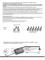
Programmieren der Zusatzfunktionen mit dem SET - Taster:
1.) Akkus vom Regler abstecken, wenn möglich Sender einschalten
2.) SET - Taste drücken und gedrückt halten und gleichzeitig den Fahrakku (bei Reglern ohne BEC
zusätzlich den Empfängerakku) mit dem Regler verbinden.
Die SET Taste muss solange gedrückt bleiben, bis der Regler 6 x kurz piepst und die grüne LED
leuchtet, sowie die rote LED während der 6 Piepstöne 6x kurz blinkt.
Während dieser Zeit lassen Sie die SET-Taste wieder los.
3.) Sie befinden sich nun im Programmauswahlmodus. Wenn Sie nicht innerhalb der nächsten 4
Sekunden die SET-Taste erneut drücken, so geht der Regler in den #0 IDA-Programmiermodus. Siehe
#0 IDA-System!
4.) Drücken Sie nun gemäß der gewünschten Programmnummer die SET-Taste so oft, wie es der
gewünschte Programmnummer entspricht. Bei jedem Tastendruck piepst der Regler 1x lang und die
rote LED blinkt dabei lange auf. Siehe Tabelle!
5.) Ca. 4s nach dem letzten Tastendruck bestätigt der Regler das Beenden der Programmeinstellung
mit 3 kurzen Piepstönen, LED rot blinkt 3x kurz, LED grün aus.
6.) Sofort darauf zeigt der Regler den Programmstart der Werteinstellung an, in dem der Regler erneut
3x kurz piepst, die rote LED 3x kurz blinkt und die grüne LED leuchtet.
7.) Drücken Sie nun die SET Taste so oft, wie der gewünschte Wert entspricht. Bei jedem Tastendruck
piepst der Regler 1x lang und die rote LED blinkt dabei lange auf.
(Wert 0 = 0x drücken, Wert 1 = 1x drücken, Wert 2 = 2x drücken....)
8.) Ca. 4s nach dem letzten Tastendruck bestätigt der Regler das Beenden der Programmeinstellung
mit 3 kurzen Piepstönen, LED rot blinkt 3x kurz, LED grün aus.
Danach kehrt der Regler in seinen normalen Betrieb zurück. Fertig!
Programmierbeispiel Zusatzfunktion: (Beispiel: Softanlauf #8 mit Hochlaufzeit 0,5s = 3)
1. Regler abstecken und
wenn möglich Sender
einschalten.
(Motor muss
angeschlossen sein)
2. SET-Taste drücken und gedrückt
halten und gleichzeitig den
Fahrakku mit dem Regler
verbinden. Taste gedrückt halten,
bis 6 kurze Pieptöne zu hören sind und
während der Piepstöne Taste loslassen.
3. Sie befinden sich jetzt
im Programmauswahlmodus.
Drücken Sie nun gemäß der
gewünschten Programmnummer
die SET-Taste so oft, wie es der
gewünschten Programmnummer
entspricht oder bleiben Sie
dementsprechend lange auf der
Taste,
ca. 4s warten!
TÖNE
LED
6x
red gn
rot
rote LED blinkt 6x,
grüne LED an
4. Nach den 4s Wartezeit blinkt
die rote LED 3x bei grüner LED aus.
Gleich darauf blinkt die rote LED
noch einmal 3x bei grüner LED an.
Der Programmstart für die
Werteeinstellung wird hiermit
signalisiert.
8x
red gn
rot
red gn
rot
red gn
rot
rote LED blinkt 8x,
grüne LED an
rote LED aus,
grüne LED an
5. Sie befinden sich jetzt
im Werteeinstellmodus.
Drücken Sie nun gemäß des
gewünschten Wertes (z. B. 3)
die SET-Taste so oft, wie es dem
gewünschten Wert entspricht oder
bleiben Sie dementsprechend
lange auf der Taste,
rote LED aus,
grüne LED an
6. Nach den 4s Wartezeit blinkt
die rote LED 3x bei grüner LED aus.
Die Programmierung ist hiermit
beendet.
max. 4s warten!
TÖNE
LED
3x
red gn
rot
3x
red gn
rot
rote LED blinkt 3x, rote LED blinkt 3x,
grüne LED an
grüne LED aus
20
3x
red gn
rot
rote LED blinkt 3x,
grüne LED an
red gn
rot
rote LED aus,
grüne LED an
3x
red gn
rot
rote LED blinkt 3x,
grüne LED aus
Programmübersicht der Zusatzfunktionen, bei Programmierung mit der
SET-Taste:
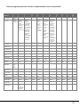
PROGRAMM WERT WERT WERT WERT WERT WERT WERT WERT WERT WERT WERT
NUMMER
0
1
2
3
4
5
6
7
8
9
10
#0
IDA-System
#1
SWITCH
IDASystem
REGLER REGLER
IMMER MIT
AN
TASTE
AN/AUS
-
-
-
-
-
-
-
-
REGLER SOFORT
AN,
ABER
MIT
TASTE
AUSSCHALTBAR
REGLER
NACH
TASTENDRUCK
ODER
16s
VOLLBREMSE
AUS
REGLER
NACH
KURZEM
TASTENDRUCK
AN/AUS
ODER
ÜBER
16s
VOLLBRMESE
AUS
REGLER
SOFORT
AN
ABER
ÜBER
TASTENDRUCK
ODER
16s
VOLLBREMSE
AUS
=6
=6
=6
=6
#2
AUTOBRK
#3
BRAKEMAX
#4 FULLBRAKE
0%
10%
20%
30%
40%
50%
60%
70%
80%
90%
100%
0%
10%
20%
30%
40%
50%
60%
70%
80%
90%
100%
0%
0%
10%
10%
20%
20%
30%
30%
40%
40%
50%
50%
60%
60%
70%
70%
80%
80%
90%
90%
100%
100%
AUS
EIN
EIN
EIN
EIN
EIN
EIN
EIN
EIN
EIN
EIN
0
1
2
3
4
5
6
7
8
9
10
2s
1s
0,7s
0,5s
0,4s
0,34s
0,3s
0,25s 0,22s
0,2s
68ms
0°
7,5°
15°
30°
30°
30°
30°
30°
30°
30°
30°
210000
U/min
2pol.
Motor
160000
120000
90000
70000
50000
40000
30000
25000
17500
12500
40A
50A
60A
70A
80A
90A
100A
110A
120A
130A
140A
40A
50A
60A
70A
80A
90A
100A
110A
120A
130A
140A
0A
1A
2A
3A
4A
5A
6A
7A
8A
9A
9A
LINEAR
SOFT
HART
HART
HART
HART
HART
HART
HART
HART
HART
0%
10%
20%
30%
40%
50%
60%
70%
80%
90%
100%
-
-
-
-
-
-
-
-
-
-
-
8kHz
mit
fester
Strombegrenzung
8kHz
mit
regelbarer
Strombegrenzung
#5
MAXREVERSE
#6
ABS
#7
AUTOGAS
#8
SOFTGAS
#9
TIMING
#10
RPMLIMIT
#11
AMP LIMIT
#12
START AMP
#13
TURBO
#14
POWERKURVE
#15
BRAKEMIN
#16
RESERVED
#17
FREQUENCY
-
21
#0
IDA-System Einstellen der Werte mit dem GMVIS-Commander:
Mit Hilfe des IDA-Systems können mit dem GMVIS-Commander 94401 ab V2005 die Daten des
Reglers wahlweise ausgelesen und/oder programmiert werden.
Wählen Sie mit dem GMVIS-Commander mit Hilfe der Pfeil rechts Taste das Menü PROGRAM aus.
Mit Hilfe der Pfeil hoch/runter Tasten können die Untermenüs ausgewählt werden.
Durch drücken der MODE - Taste erreicht man den Einstellmodus, indem wie in den Lademenüs die
gewünschten Werte eingestellt werden. Beim Drücken der START/STOP - Taste werden die Daten
abgespeichert und gesendet. Bei jedem Drücken der START/STOP -Taste werden die Daten erneut
gesendet.
Nach dem Drücken der Timer-Taste können innerhalb der nächsten 30s Daten empfangen werden.
#0
IDA-System (RS232) Daten senden und empfangen mit dem GMVIS-Commander:
Trennen Sie den GMVIS-Commander von der Spannungsquelle und stecken Sie den Genius Regler
von der Spannungsversorgung aus.
Verbinden Sie das RS232-Schnittstellenkabel Best.-Nr. 2894.5 mit dem Genius Regler. Das braune
Kabel des #2894.5 muss dabei am GMVIS-Commander nach rechts zeigen!
Verbinden Sie nun den Eingang des GMVIS-Commanders mit der vorgesehenen Spannungsquelle (1214V)
Stellen Sie wie vorher beschrieben den GMVIS-Commander 94401 auf den PROGRAM -Modus ein.
Übertragen der Reglerdaten von und zum GMVIS-Commander:
Wenn sich der GMVIS-Commander im PROGRAMM - Modus befindet können die Daten des Genius
Reglers wie folgt ausgelesen werden:
1.) Drücken Sie die TIMER - Taste des GMVIS-Commanders:
2.) Im Display erscheint nun in der ersten Zeile rechts (read data): RD?
Sollte einmal RD? 251 erscheinen, so brechen Sie mit der START/STOP - Taste den Vorgang ab und
drücken die TIMER - Taste erneut, bis RD?
Oder RD? 000 oder ein anderer Wert als 251 erscheint.
Wenn Sie keine Daten aus dem Regler auslesen möchten, dann drücken Sie die START/STOP - Taste
oder rufen Sie den RD? - Modus erst gar nicht auf.
3.) Drücken Sie nun die SET-Taste des Genius Reglers während Sie den Genius Regler mit der
Spannungsquelle verbinden und lassen Sie den Taster während der sechs kurzen Blinkzeichen der
roten LED und sechs kurzen Piepstöne (grüne LED an) (siehe Programmieren der Zusatzfunktionen
Programmmodus #0) wieder los!
4.) Nach ca. 4s blinkt die rote LED 3x kurz und der Regler piepst 3x kurz (grüne LED aus).
Sofort danach blinkt die rote LED 3x kurz und der Regler piepst 3x kurz (grüne LED an).
5.) Nun ist die grüne und rote LED aus. Während dieser Zeit werden die Daten des Genius Reglers an
den GMVIS-Commander gesendet.
Möchten Sie die Daten an den GMVIS-Commander übertragen, so muss sich dieser im RD? -Modus
befinden. Die empfangenen Daten werden dabei im Display kurz angezeigt. z. B. RD? 100
Der RD? - Modus kann vor der Datenübertragung mit der START/STOP - Taste abgebrochen werden,
wenn Sie z. B. doch keine Daten übernehmen wollen und direkt die im GMVIS-Commander
gespeicherten Daten übertragen möchten.
6.) Nachdem der Regler die Daten gesendet hat, leuchtet die LED grün. Der Genius Regler wartet nun
auf Daten.
7.) Zur Datenübertragung der Daten im GMVIS-Commander drücken Sie nun die START/STOP - Taste
des GMVIS-Commanders.
8.) Ansonsten, wenn Sie die Daten aus dem Regler nur auslesen möchten und diesen nicht mit dem
GMVIS-Commander neu programmieren möchten, so drücken Sie kurz die SET-Taste des Genius
Reglers.
9.) Nach dem Empfang der Daten des GMVIS-Commanders oder nach dem Drücken der SET-Taste
des Reglers blinkt die rote LED 3x kurz und der Regler piepst 3 x kurz und ist nun nach dem Entfernen
des RS232-Kabels wieder fahrbereit.
22
#0
IDA-System Einstellen der Werte mit dem PC:
Mit Hilfe des IDA-Systems können mit dem PC mit der Software die Daten des Reglers wahlweise
ausgelesen und/oder programmiert werden. Die Reglerprogrammiersoftware können Sie bei www.gmracing.de im Download-Bereich herunterladen.
Wählen Sie im Programm die gewünschte Schnittstelle aus.
Mit der Maus können Sie die gewünschten Einstellwerte einstellen.
#0
IDA-System (RS232) Daten senden und empfangen mit dem PC:
Stecken Sie den Genius Regler von der Spannungsversorgung aus.
Verbinden Sie das RS232-PC Schnittstellenkabel Best.-Nr. 2894.6 mit der gewünschten RS232Schnittstelle mit dem PC und mit dem Genius Regler.
Klicken Sie nach dem Einstellen der richtigen COM-Schnittstelle auf Enable COM.
Übertragen der Reglerdaten von und zum PC:
Wenn Sie mit der Maus auf GET DATA klicken, so können die Daten des Genius Reglers wie folgt
ausgelesen werden:
1.) Drücken Sie nun die SET-Taste des Genius Reglers während Sie den Genius Regler mit der
Spannungsquelle verbinden und lassen Sie den Taster während der sechs kurzen Blinkzeichen der
roten LED und sechs kurzen Piepstöne (grüne LED an) (siehe Programmieren der Zusatzfunktionen
Programmmodus #0) wieder los!
2.) Nach ca. 4s blinkt die rote LED 3x kurz und der Regler piepst 3x kurz (grüne LED aus).
Sofort danach blinkt die rote LED 3x kurz und der Regler piepst 3x kurz (grüne LED an).
3.) Nun ist die grüne und rote LED aus. Während dieser Zeit werden die Daten des Genius Reglers an
den PC gesendet.
Möchten Sie die Daten an den PC übertragen, so müssen Sie sich im Modus GET DATA befinden.
Der Empfangsmodus kann mit CANCEL abgebrochen werden, wenn Sie z. B. doch keine Daten
übernehmen wollen und direkt die im PC gespeicherten Daten übertragen möchten.
Möglicherweise ist es mit dem Schnittstellenkabel 2894.6 bei Systemdifferenzen nur möglich Daten zum
Regler zu Senden, jedoch nicht auszulesen!
4.) Nachdem der Regler die Daten gesendet hat, leuchtet die LED grün. Der Genius Regler wartet nun
auf Daten.
5.) Zur Datenübertragung der Daten vom PC klicken Sie nun auf SEND DATA.
6.) Ansonsten, wenn Sie die Daten aus dem Regler nur auslesen möchten und diesen nicht mit dem
GMVIS-Commander neu programmieren möchten, so drücken Sie kurz die SET-Taste des Genius
Reglers.
7.) Nach dem Empfang der Daten vom PC oder nach dem Drücken der SET-Taste des Reglers blinkt
die rote LED 3x kurz und der Regler piepst 3 x kurz und ist nun nach dem Entfernen des RS232-Kabels
wieder fahrbereit.
23
Programmablauf IDA-System, Zusatzfunktionen:
Programmierung IDA-System:
1. Regler abstecken und
wenn möglich Sender
einschalten.
(Motor muss
angeschlossen sein)
Programmierkabel in den
Programmierstecker und
in den PC bzw. GM-VIS
Commander richtig
einstecken, siehe S. 22, 23 .
2. SET-Taste drücken und gedrückt
halten und gleichzeitig den
Fahrakku mit dem Regler
verbinden. Taste gedrückt halten,
bis 6 kurze Pieptöne zu hören sind und
während der Piepstöne Taste loslassen.
Programmierstecker
TÖNE
LED
red gn
rot
red gn
rot
red gn
rot
red gn
rot
red gn
rot
red gn
rot
rote LED blinkt 6x,
grüne LED an
3. Sie befinden sich jetzt
im Programmauswahlmodus.
Wenn Sie nicht innerhalb der
nächsten 4s die SET-Taste
erneut drücken, so geht der
Regler wie gewünscht in das
IDA-Programmiersystem #0.
TÖNE
LED
4. Nach den 4s
Wartezeit blinkt
die rote LED 3x
bei grüner LED aus.
4s warten!
red gn
rot
rote LED aus,
grüne LED an
red gn
rot
red gn
rot
5. Die grüne und rote LED ist
nun aus.
Während dieser Zeit werden die
Daten des Reglers an
den GMVIS-Commander bzw. PC
gesendet. Möchten Sie Daten auslesen, so muss sich der PC bzw.
der GMVIS-Commander im
Modus Empfangen von Daten
befinden.
red gn
rot
red gn
rot
rote LED aus,
grüne LED aus
rote LED blinkt 3x,
grüne LED aus
6. Wenn die LED grün leuchtet,
so wartet der Regler auf Daten
vom PC oder GMVIS-Commander.
Wenn Sie nun die Werte vom PC
oder GMVIS-Commander übernehmen
wollen, dann starten Sie jetzt die Datenübertragung, ansonsten drücken Sie
die SET-Taste um das Programm zu
verlassen.
7. Nach dem Empfangen der Daten oder nach dem Drücken
der SET-Taste bestätigt der Regler das Programmende mit
3 kurzen roten LED Blinkzeichen. Entfernen Sie jetzt den
Programmierstecker. Das BEC-System kann nach der
Programmierung abgeschaltet sein und muss in diesem Fall
durch Drücken der SET-Taste wieder eingeschaltet werden,
ansonsten startet der Regler den normalen Betriebsmodus.
TÖNE
LED
red gn
rot
rote LED aus,
grüne LED an
24
red gn
rot
red gn
rot
red gn
rot
rote LED blinkt 3x,
grüne LED aus
Fehlermeldungen:
1.)
1s
3x
1s
3x
red gn
rot
1s
3x
red gn
rot
rote LED blinkt 3x, rote LED blinkt 3x, rote LED blinkt 3x,
grüne LED aus
grüne LED aus
grüne LED aus
3x
red gn
rot
rote LED blinkt 3x,
grüne LED aus
1s
1s
1s
3x
red gn
rot
3x
red gn
rot
rote LED blinkt 3x,
grüne LED aus
red gn
rot
3x
red gn
rot
rote LED blinkt 3x, rote LED blinkt 3x,
grüne LED aus
grüne LED aus
Fehlerbeschreibung:
Bei Dauerpiepsen (je 3x kurz ) und/oder Dauerblinken der roten LED (3x kurz) ist beim Anstecken des
Reglers an die Betriebsspannung entweder der Motor falsch oder nicht angeschlossen.
Fehlerbehebung:
Motoranschlüsse überprüfen und richtig anschließen.
2.)
1s
red gn
rot
1s
red gn
rot
1s
red gn
rot
1s
red gn
rot
1s
red gn
rot
1s
red gn
rot
1s
red gn
rot
red gn
rot
Fehlerbeschreibung:
Bei Dauerpiepsen (1x lang) und Dauerblinken der roten LED (1x lang) ist die Betriebsspannung zu hoch.
Fehlerbehebung:
Für den Betriebsmodus die richtige Betriebsspannung wählen, indem ein Akku mit der vorgeschriebenen
Zellenzahl verwendet wird.
3.)
Fehlerbeschreibung:
Der Regler zeigt keinerlei Funktion.
Fehlerbehebung:
Betriebsspannung zu niedrig. Laden Sie den Antriebsakku und überprüfen Sie die Anschlüsse auf eine gute
Verbindung.
Führt dies nicht zum Erfolg, schicken Sie den Regler zur Überprüfung ein.
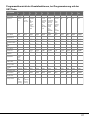
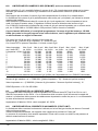
Technische Daten:
Bezeichnung:
Genius 80
Genius 30
Best.-Nr.
2894
2895
Betriebsspannung in V:
7,2-12
7,2-14,8
Zellenzahl Ni-MH, Ni-Cd:
6 - 10
6-12
Zellenzahl LiPo:
2 3
2-4
Dauerstrom (bürstenlose M.)
80A
30A
Strom kurzzeitig 10s
160A
60A
Impulsstrom bei 25°C
300A
90A
Innenwiderstand bei 20°C ca.
0,001
0,004
Spannungsabfall @20A ca.
0,02V
0,008V
Temperaturabschaltung:
ja
ja
Unterspannungsabregelung:
ja
ja
Unterspannungsabschaltung:
im Modellmodus 1-3 (alle)
Rückwärtsfahrt:
im Modellmodus 4 (alle)
BEC:
5,8V/kurzz. 4A (alle)
Max. BEC Verlustleistung:
2,5W
2,5W
Taktfrequenz:
8kHz
8kHz
Abm. in mm ohne Kond. ca.:
48x31x15
55x27x10
Abm. in mm mit Kond. ca.:
wahlweise
70x27x13
Gewicht ohne Kabel ca.:
50g
18g
Gewicht mit Kabel ca.:
90g
28g
* mit Optokoppler 2894.3 und mit 4-Zellen Empfängerakku
Zubehör:
2894.1
2894.2
2894.3
2894.4
2894.5
2894.6
2894.7
Genius 40
2896
7,2-14.8 (*19,2)
6 - 12(*16)
2 - 4 (*5)
40A
80A
150A
0,003
0,06V
ja
ja
Genius 70
2897
7,2-14.8 (*19,2)
6 - 12 (*16)
2 - 4 (*5)
70A
140A
300A
0,0015
0,03V
ja
ja
2,5W
8kHz
50x27x10
70x27x13
18g
45g
2,5W
8kHz
50x27x15
70x27x15
33g
70g
Ersatzaufkleber Genius 80
Ersatzgehäuse Genius 80
Optokoppler für Galvanische Trennung für Genius und andere BEC-Regler
Sensoradapterkabel (Novak/Reedy - Motoren)
Schnittstellenkabel GM-VIS Commander/Genius
Schnittstellenkabel PC/Genius
Empfängerkabel für Genius 80 (Servokabel)
25
Kurzanleitung:
Anschluss des Genius-Reglers:
Anschluss eines bürstenlosen Motors (Motorkonfiguration #1)
schwarz
-
-
B
M
Powerkondensator
+
Antriebsakku
+
A
Empfängerkabel
C
gelb
Programmierstecker und
Stecker für Hallsensoren
rot
B
rot
A
blau
C
Je nach Modus 1-4
kurze Pieptöne
TÖNE
LED
red gn
rot
...
...
red gn
rot
rote LED blinkt,
grüne LED an
Anschluss eines Bürstenmotors für die Funktionen
vorwärts/Motor aus/(Bremse) (Motorkonfiguration #2)
Empfängerkabel
C
Powerkondensator
gelb
+
Antriebsakku
Programmierstecker und
Stecker für Hallsensoren
rot
M
-
A, B, C
+
-
schwarz
-
blau
B
rot
blau
+
A
rot
Akku+
Je nach Modus 1-4
kurze Pieptöne
...
...
TÖNE
LED
red gn
rot
red gn
rot
red gn
rot
-
rot
B
red gn
rot
Antriebsakku
Programmierstecker und
Stecker für Hallsensoren
rot
blau
A
A
Je nach Modus 1-4
kurze Pieptöne
TÖNE
LED
red gn
rot
...
...
red gn
rot
rote LED blinkt,
grüne LED an
26
-
Powerkondensator
+
M
red gn
rot
Empfängerkabel
gelb C
+
C
red gn
rot
schwarz
-
+
red gn
rot
rote LED blinkt 6x,
grüne LED an
rote LED blinkt,
grüne LED an
Anschluss eines Bürstenmotors für die Funktionen
vorwärts/Motor aus/(Bremse)/rückwärts (Motorkonfiguration #3)
red gn
rot
red gn
rot
red gn
rot
red gn
rot
red gn
rot
red gn
rot
rote LED blinkt 6x,
grüne LED an
red gn
rot
Modus-Programmierung GENIUS:
5. innerhalb der nächsten 4s Senderknüppel
auf die Position “Vollgas” und “Vollbremse”
stellen und auf der Position “Vollbremse”
halten, bis die Piepstöne für die Bestätigung
für Modus 1 ertönen.
Programmierung Modus 1 (vorwärts mit Bremse) Motorsegler:
2. Senderknüppel
auf die gewünschte
Neutralposition
stellen
1. Sender und dann Regler
einschalten/einstecken
(Motor muss
angeschlossen sein)
4.
ca. 2s warten,
bis grüne LED
leuchtet
3. SET-Taste für
ca. 4s drücken,
bis rote LED
leuchtet
Je nach Modus 1-4
kurze Pieptöne
LED
“Vollgas”
...
...
red gn
rot
rote LED blinkt,
grüne LED an
rote LED an,
grüne LED aus
TÖNE
red gn
rot
1s
Pause
red gn
rot
2x
red gn
rot
red gn
rot
red gn
rot
rote LED aus,
grüne LED an
2. Senderknüppel
auf die gewünschte
Neutralposition
stellen
Je nach Modus 1-4
kurze Pieptöne
LED
red gn
rot
...
...
4.
ca. 2s warten,
bis grüne LED
leuchtet
3. SET-Taste für
ca. 4s drücken,
bis rote LED
leuchtet
“Neutral=Motor aus”
“Vollgas”
1s
Pause
red gn
rot
red gn
rot
rote LED blinkt,
grüne LED an
2x
red gn
rot
red gn
rot
red gn red gn
rot
rot
rote LED aus,
grüne LED an
rote LED an,
grüne LED aus
Programmierung Modus 3 (vorwärts mit Drehzahlregelung) Heli:
1. Sender und dann Regler
einschalten/einstecken
(Motor muss
angeschlossen sein)
3. SET-Taste für
ca. 4s drücken,
bis rote LED
leuchtet
2. Senderknüppel
auf die gewünschte
Neutralposition
stellen
LED
red gn
rot
“Vollgas”
“Neutral=Motor aus”
...
...
red gn
rot
“Neutral=Motor aus”
2x
...
...
red gn
rot
rote LED blinkt,
grüne LED an
3x
3x
“Gas bis zur gewünschten Drehzahl”
3. SET-Taste für
ca. 4s drücken,
bis rote LED
leuchtet
red gn
rot
red gn
rot
8.
Stellen Sie
den Senderknüppel
wieder auf die
Position “Neutral”
7. Geben Sie so
viel Gas, bis die
gewünschte
maximale
Drehzahl erreicht
ist.
2. Senderknüppel
auf die gewünschte
Neutralposition
stellen
3x
4.
ca. 2s warten,
bis grüne LED
leuchtet
red gn
rot
“Neutral=Motor aus”
5. innerhalb der nächsten 4s Senderknüppel
auf die Position “Vollgas” und “Vollbremse”
und erneut “Vollgas” und “Vollbremse”
stellen und auf der Position “Vollbremse”
halten, bis die Piepstöne für die Bestätigung
für Modus 4 ertönen.
Je nach Modus 1-4
kurze Pieptöne
red gn
rot
“Neutral=Motor aus” “Vollgas”
red gn
rot
red gn
rot
Programmierung Modus 4 (vorwärts/Bremse/rückwärts) Auto/Boot:
1. Sender und dann Regler
einschalten/einstecken
(Motor muss
angeschlossen sein)
LED
red gn
rot
1s
Pause
red gn
rot
6. Regler aktivieren,
indem der Senderknüppel
auf “Neutral” gestellt wird
TÖNE
red gn
rot
rote LED blinkt, rote LED blinkt,
grüne LED aus grüne LED an
5. innerhalb der nächsten 4s Senderknüppel
auf die Position “Vollgas” und “Neutral” und
wieder “Vollgas” stellen und auf der Position
“Vollgas” halten, bis die Piepstöne für die
Bestätigung für Modus 3 ertönen.
4.
ca. 2s warten,
bis grüne LED
leuchtet
Je nach Modus 1-4
kurze Pieptöne
TÖNE
red gn
rot
rote LED blinkt, rote LED blinkt,
grüne LED aus grüne LED an
5. innerhalb der nächsten 4s Senderknüppel
auf die Position “Vollgas” stellen und auf
der Position “Vollgas” halten, bis die Piepstöne
für die Bestätigung für Modus 2 ertönen.
Programmierung Modus 2 (vorwärts ohne Bremse) Motormodelle:
1. Sender und dann Regler
einschalten/einstecken
(Motor muss
angeschlossen sein)
TÖNE
“Vollbremse”
“Vollgas”
“Vollbremse”
“Vollgas”
“Vollbremse”
1s
Pause
red gn
rot
rote LED an,
grüne LED aus
2x
red gn
rot
red gn
rot
rote LED aus,
grüne LED an
4x
red gn
rot
rote LED blinkt,
grüne LED aus
4x
red gn
rot
rote LED blinkt,
grüne LED an
27
Programmübersicht der Zusatzfunktionen, bei Programmierung mit der SET-Taste:
PROGRAMM WERT WERT WERT WERT WERT WERT WERT WERT WERT WERT WERT
NUMMER
0
1
2
3
4
5
6
7
8
9
10
#0
IDA-System
#1
SWITCH
IDASystem
REGLER REGLER
IMMER MIT
AN
TASTE
AN/AUS
-
-
-
-
-
-
-
-
REGLER SOFORT
AN,
ABER
MIT
TASTE
AUSSCHALTBAR
REGLER
NACH
TASTENDRUCK
ODER
16s
VOLLBREMSE
AUS
REGLER
NACH
KURZEM
TASTENDRUCK
AN/AUS
ODER
ÜBER
16s
VOLLBRMESE
AUS
REGLER
SOFORT
AN
ABER
ÜBER
TASTENDRUCK
ODER
16s
VOLLBREMSE
AUS
=6
=6
=6
=6
#2
AUTOBRK
#3
BRAKEMAX
#4 FULLBRAKE
0%
10%
20%
30%
40%
50%
60%
70%
80%
90%
100%
0%
10%
20%
30%
40%
50%
60%
70%
80%
90%
100%
0%
0%
10%
10%
20%
20%
30%
30%
40%
40%
50%
50%
60%
60%
70%
70%
80%
80%
90%
90%
100%
100%
AUS
EIN
EIN
EIN
EIN
EIN
EIN
EIN
EIN
EIN
EIN
0
1
2
3
4
5
6
7
8
9
10
2s
1s
0,7s
0,5s
0,4s
0,34s
0,3s
0,25s 0,22s
0,2s
68ms
0°
7,5°
15°
30°
30°
30°
30°
30°
30°
30°
30°
210000
U/min
2pol.
Motor
160000
120000
90000
70000
50000
40000
30000
25000
17500
12500
40A
50A
60A
70A
80A
90A
100A
110A
120A
130A
140A
40A
50A
60A
70A
80A
90A
100A
110A
120A
130A
140A
0A
1A
2A
3A
4A
5A
6A
7A
8A
9A
9A
LINEAR
SOFT
HART
HART
HART
HART
HART
HART
HART
HART
HART
0%
10%
20%
30%
40%
50%
60%
70%
80%
90%
100%
-
-
-
-
-
-
-
-
-
-
-
8kHz
mit
fester
Strombegrenzung
8kHz
mit
regelbarer
Strombegrenzung
#5
MAXREVERSE
#6
ABS
#7
AUTOGAS
#8
SOFTGAS
#9
TIMING
#10
RPMLIMIT
#11
AMP LIMIT
#12
START AMP
#13
TURBO
#14
POWERKURVE
#15
BRAKEMIN
#16
RESERVED
#17
FREQUENCY
28
-
Programmablauf IDA-System, Zusatzfunktionen:
Programmierung IDA-System:
1. Regler abstecken und
wenn möglich Sender
einschalten.
(Motor muss
angeschlossen sein)
Programmierkabel in den
Programmierstecker und
in den PC bzw. GM-VIS
Commander richtig
einstecken, siehe S.22,23 .
3. Sie befinden sich jetzt
im Programmauswahlmodus.
Wenn Sie nicht innerhalb der
nächsten 4s die SET-Taste
erneut drücken, so geht der
Regler wie gewünscht in das
IDA-Programmiersystem #0.
2. SET-Taste drücken und gedrückt
halten und gleichzeitig den
Fahrakku mit dem Regler
verbinden. Taste gedrückt halten,
bis 6 kurze Pieptöne zu hören sind und
während der Piepstöne Taste loslassen.
4. Nach den 4s Wartezeit blinkt
die rote LED 3x bei grüner LED aus.
Programmierstecker
4s warten!
TÖNE
LED
red gn
rot
red gn
rot
red gn
rot
red gn
rot
red gn
rot
rote LED blinkt 6x,
grüne LED an
5. Die grüne und rote LED ist
nun aus. Während dieser Zeit
werden die Daten des Reglers an
den GMVIS-Commander bzw. PC
gesendet. Möchten Sie Daten auslesen, so muss sich der PC bzw.
der GMVIS-Commander im
Modus Empfangen von Daten
befinden.
red gn
rot
red gn
rot
red gn
rot
rote LED aus,
grüne LED an
6. Wenn die LED grün leuchtet,
so wartet der Regler auf Daten
vom PC oder GMVIS-Commander.
Wenn Sie nun die Werte vom PC
oder GMVIS-Commander übernehmen
wollen, dann starten Sie jetzt die Datenübertragung, ansonsten drücken Sie
die SET-Taste um das Programm zu
verlassen.
7. Nach dem Empfangen der Daten oder nach dem Drücken
der SET-Taste bestätigt der Regler das Programmende mit
3 kurzen roten LED Blinkzeichen. Entfernen Sie jetzt den
Programmierstecker. Das BEC-System kann nach der
Programmierung abgeschaltet sein und muss in diesem Fall
durch Drücken der SET-Taste wieder eingeschaltet werden,
ansonsten startet der Regler den normalen Betriebsmodus.
red gn
rot
rote LED aus,
grüne LED an
rote LED aus,
grüne LED aus
red gn
rot
rote LED blinkt 3x,
grüne LED aus
red gn
rot
red gn
rot
red gn
rot
red gn
rot
red gn
rot
rote LED blinkt 3x,
grüne LED aus
Programmierbeispiel Zusatzfunktion mit der SET-Taste: (Beispiel: Softanlauf #8 mit Hochlaufzeit 0,5s = 3)
1. Regler abstecken und
wenn möglich Sender
einschalten.
(Motor muss
angeschlossen sein)
2. SET-Taste drücken und gedrückt
halten und gleichzeitig den
Fahrakku mit dem Regler
verbinden. Taste gedrückt halten,
bis 6 kurze Pieptöne zu hören sind und
während der Piepstöne Taste loslassen.
3. Sie befinden sich jetzt
im Programmauswahlmodus.
Drücken Sie nun gemäß der
gewünschten Programmnummer
die SET-Taste so oft, wie es der
gewünschten Programmnummer
entspricht oder bleiben Sie
dementsprechend lange auf der
Taste,
ca. 4s warten!
TÖNE
LED
6x
red gn
rot
8x
red gn
rot
red gn
rot
rote LED blinkt 8x,
grüne LED an
rote LED blinkt 6x,
grüne LED an
4. Nach den 4s Wartezeit blinkt
die rote LED 3x bei grüner LED aus.
Gleich darauf blinkt die rote LED
noch einmal 3x bei grüner LED an.
Der Programmstart für die
Werteeinstellung wird hiermit
signalisiert.
red gn
rot
rote LED aus,
grüne LED an
6. Nach den 4s Wartezeit blinkt
die rote LED 3x bei grüner LED aus.
Die Programmierung ist hiermit
beendet.
5. Sie befinden sich jetzt
im Werteeinstellmodus.
Drücken Sie nun gemäß des
gewünschten Wertes (z. B. 3)
die SET-Taste so oft, wie es dem
gewünschten Wert entspricht oder
bleiben Sie dementsprechend
lange auf der Taste,
max. 4s warten!
TÖNE
LED
3x
red gn
rot
3x
red gn
rot
rote LED blinkt 3x, rote LED blinkt 3x,
grüne LED aus
grüne LED aus
3x
red gn
rot
rote LED blinkt 3x,
grüne LED an
red gn
rot
rote LED aus,
grüne LED an
3x
red gn
rot
rote LED blinkt 3x,
grüne LED aus
29
Änderungen sowie Liefermöglichkeit vorbehalten. Für Druckfehler kann keine Haftung übernommen werden.
30
24
mesi
meses
mois
Monaten
month
Name des Käufers
Owner’s name
Nom de l’acheteur
Straße Wohnort
Übergabedatum
Date of purchase/delivery
Date de remise
La sociéte Graupner GmbH&Co.KG, Henriettenstr. 94-96, 73230 Kirchheim/Teck, Allemagne
accorde sur ce produit une garantie de 24 mois à partir de la date d’achat.
La garantie prend effect uniquement sur les vices de fonctionnement et de matériel du produit
acheté. Les dommages dûs à de l’usure, à de la surcharge, à de mauvais accessoires ou à d’une
application inadaptée, sont exlus de la garantie.
Cette garantie ne remet pas en cause les droits et prétentions légaux du consommateur.
Avant toute réclamation et tout retour du prouit, veuillez s.v.p. Contrôler et noter exactement les
défauts ou vices du produit, car tout autre relatif au produit vous sera facturé.
Graupner GmbH & Co.KG, Henriettenstr. 94-96, 73230 Kirchheim/Teck, Germany guarantees this
product for a period of 24 month from date of purchase.
The guarantee applies only to such material or operational defects which are present at the time of
purchase of the product.
Damage due to wear, overloading, incompetent handling or the use of incorrect accessories is not
covered by the guarantee.
The user’s legal rights and claims under guarantee are not affected by this guarantee.
Please check the product carefully for defects before you make a claim or send the item to us,
since we are obliged to make a charge for our costs if the product is found to be free of faults.
Die Firma Graupner GmbH& Co. KG, Henriettenstr. 94-96, 73230 Kirchheim/Teck, Deutschland
gewährt ab dem Kaufdatum auf dieses Produkt eine Garantie von 24 Monaten.
Die Garantie gilt nur für die bereits beim Kauf des Produktes vorhandenen Material- oder
Funktionsmängel. Schäden die auf Abnutzung, Überlastung, falsches Zubehör oder
unsachgemäße Behandlung zurückzuführen sind, sind von der Garantie ausgeschlossen.
Die gesetzlichen Rechte und Gewährleistungsansprüche des Verbrauchers werden durch diese
Garantie nicht berührt. Bitte überprüfen Sie vor einer Reklamation oder Rücksendung des Produkt
genau auf Mängel, da wir Ihnen bei Mängelfreiheit die entstandenen Kosten in Rechnung stellen
müssen.
Garantie de
Garanzia di
Garantia de
Garantie von
Warrantied for
Italia
GiMax
Via Manzoni, no. 8
I 25064 Gussago
(+39)3 0 25 22 73 2
Espana
FA - Sol S.A.
C. Avinyo4
E 08240 Maneresa
(+34) 93 87 34 23 4
Ceská Republika/Slovenská Republika
RC Service Z. Hnizdil
Letecka 666/22
CZ 16100 Praha 6 - Ruzyne
(+42) 2 33 31 30 95
UK
GLIDERS
Brunel Drive
Newark, Nottinghamshire
NG24 2EG
(+44) 16 36 63 05 39
France
Graupner France
Gérald Altmayer
86, rue ST. Antoine
57601 Forbach-Oeting
(+33) 3 87 85 62 12
Sverige
Baltechno Electronics
Box 5307
S 40227 Göteborg
(+46) 31 70 73 00 0
Belgie/Belgique/Nederland
Jan van Mouwerik
Slot de Houvelaan 30
NL 3155 Maasland VT
(+31) 10 59 13 59 4
Schweiz
Graupner Service
Postfach 92
CH 8424 Embrach-Embraport
(+41) 43 26 66 58 3
Luxembourg
Kit Flammang
129, route d’Arlon
8009 Strassen
(+35)23 12 23 2
Servicehotline: Tel.: (+49)(01805)472876
Mo-Fr 9.30-11.30 und 13.00-15.00Uhr
Graupner Zentralservice
Graupner GmbH&Co.KG
Postfach 1242
D-73230 Kirchheim/Teck
Tel.: (+49)(07021)722130
Servicestellen / Service / Service après-vente
Instruction Manual
brushless + brushed
Graupner - GENIUS 30 #2895
Graupner - GENIUS 40 #2896
Graupner - GENIUS 70 #2897
GM - GENIUS 80 #2894
5 Congratulations for buying GM-Racing's Genius Controller for conventional and brushless motors,
probably the best and most universal controller for use in contest world-wide. It is adapted for use with
brushless motors with or without Hall sensors. When you connect a brushless motor with Hall sensors
made by GM-Racing the controller automatically reads out the positions of the Hall sensors on the first
power impulse after connecting and thus makes its additional controlling sensitivity available. During our
tests, however, the controller proved so sentitive that there appeared to be no need for using the more
expensive sensor-equipped motors. With this controller, Ralf Helbing is extending his series of
successful controllers, which won numerous World and European Championships, as well as national
competitions. Genius controllers are again offering a new challenge in functionality, size, and controlling
attitudes.
Important notice:
Please read this manual carefully before using your controller. Only then can you have full profit of the
potential of your controller, and avoid mistakes.
Characteristics:
GM-Racing controllers are packed with the latest components. Functionality, life time, state-of-the-art
features, functional design, and ideal component sizes have been given the greatest consideration. The
software which has been developed and continually improved by our team stands in the first line for
simplicity and precision of the settings. Our “Easy Set System”, in connection with the “IDA System”,
enables you to set each of its functions within seconds, either with or without the help of the GMVIS
Commander 94401 (software version V2005 or later). With a few clicks you will be able to adapt the
controller and thus the driving attitudes of your model to the environment. Still the controller can be used
on the spot, without any programming, in the factory settings.
Factory settings for this controller include its use with both NiMH and NiCD, as well as LiPo batteries.
In modes 1-3, the controller automatically determines the tension of the drive battery after plugging it in,
and then also automatically disconnects power when the tension drops below 5/8th of the start-up
tension, so as to avoid a deep discharge of LiPo / LiIo, or NiMH, and NiCd cells. One condition for this
function is that the battery pack is well-balanced, with every cell having the same capacity.
Further on the controller automatically determines on plugging-in whether a conventional or a brushless
motor (sensor-equipped or not) has been connected.
Caution! When using a conventional (brush) motor in configuration #4 to make the reverse gear
available, use only batteries up to 9.6V.
Main programmable functions:
- Mode 1 (forward, with brakes): motorized sailplane models (all models), with LiPo switch-off and revs
limitation at 180.000 RPM on 2-pole motors
- Mode 2 (forward, no brakes available): motorized airplane models or racing boats with LiPo switch-off,
RPM limitation at 120.000 RPM on 2-pole motors
- Mode 3 (forward, no brakes, RPM limitation): heli models with LiPo switch-off (this mode is available
for brushless motors only!), RPM limitation at 180.000 RPM on 2-pole motors
- Mode 4 (forward with brakes, reverse available): motor car models, boats, trucks with LiPo switch-off
for 2-cell-batteries, push button used as ON/OFF switch. RPM limitation at 180.000 RPM on 2-pole
motors
For a detailed description of the factory settings see Main functions, pages 9 and following
Other features:
- Voltage control
- Powerful BEC system
- Digital power settings adaptation in mode #4
- Re-charging batteries while breaking
- Red and green LEDs for easy programming
- Over-temperature switch-off
-…
2
Supplementary programmable functions:
#1 Push-button ON/OFF switch for the controller
#2 Automatic brakes
#3 Max. brakes
#4 Slam brakes
#5 Max reverse speed
#6 ABS
#7 Automatic throttle
#8 Soft start-up
#9 Timing
(only with brushless motors)
#10 Revs limitation
(only with brushless motors)
(in mode 3 = heli mode: RPM control)
#11 Max current limitation
#12 Max start-up current limitation
#13 Turbo mode
#14 Power curves
#15 Min. brakes
#16 Reserved
#17 Frequency
Content:
Warnings.............................................................................................................................. 4
Installing the controller in the model..................................................................................... 5
Connecting the controller to the receiverer........................................................................... 5
Connecting a brushless motor to the controller (Motorconfiguration #1).............................. 6
Connecting a brushed motor to the controller (forward/motor stop/brake) #2...................... 7
Connecting a brushed motor (forward/motor stop/brake/reverse) #3................................... 8
Adjusting the controller to the transmitter stick travel, Programming the main functions.... 9-14
Reset the values of the supplementary functions to the factory settings.............................. 9-14
Programming mode #1 (forward, with brake). (f. e. folding prop air planes)......................... 10
Programming mode #2 (forward, no brake) (motorplanes)....................................................11
Programming mode #3 (forward, no brake, with rpm regulation) Heli................................... 12-13
Programming mode #4 (forward with brake and reverse) Car/Boat..................................... 14
Activating reverse gear/ forward gear................................................................................... 15
Supplementary functions...................................................................................................... 15-19
Programming the supplementary functions with the SET-button.......................................... 20-21
IDA-System: Programming the values with the GMVIS-Commander................................... 22
IDA-System: Programming the values with the PC............................................................... 23
Programming overview IDA-System, supplementary functions............................................ 24
failure announcement........................................................................................................... 25
Technical specifications....................................................................................................... 25
Accesoires........................................................................................................................... 25
short instruction overview..................................................................................................... 26-29
Service................................................................................................................................. 30
3
Warnings:
- The controller's CE certificate doesn't unbind users from their obligation to use ultimate caution
- Should the motor refuse to start up, or after a crash, then you should immediately set the transmitter's
control stick to the OFF position to avoid any overload to the controller. Set the RPM limitation to 20
= 120.000 RPM or less, and select a softer start-up for a better and smoother start.
- Use only motors delivered by GM-Racing or Graupner which are designed for the intended range of
voltages!
- Use only high performance batteries by Graupner or GM-Racing. Using batteries with an
increased internal resistance may lead to the destruction of the controller!
- Never leave your transmitter unattended when a battery is connected. In case of a deficiency this may
cause an outbreak of fire on the model or its environment.
- Neither the controller nor any other electronic components should ever come in touch with water.
Protect the controller against dust, dirt, humidity, vibrations, or other dangerous elements (with the
exception of water-sealed controllers).
- Never run the motor on a seperate battery while the motor is connected to the controller. This may
destroy the controller, and leads to the loss of our warranty.
- Never mix up polarities. Use plug systems which offer protection against wrong polarity. Avoid
short-circuiting and blocking the motors.
- All cables and connectors should have good insulation. Short-circuits may lead to the destruction of
your motor.
- This product isn't designed for use by children under the age of 14, it isn't a toy!
- GM-controllers are designed for use in battery-driven, radio-controlled models only, any other use
is not permissible. Using this device on a passenger-carrying model is forbidden!
- Motors, gears or gearboxes, and propellers are dangerous objects. Never keep next to or in front of
the danger area of the drive!
- Technical defects or failures of mechanical or electronic parts may lead to an unexpected start-up of
the motor, with parts of it flying off, maybe causing severe injuries.
- Always check the service range of transmission of your model first thing while it's still on the
ground (hold the model tightly!).
- Don't make any changes on the structure and design of your controller unless they are described in
the manual!
- Limited warranty: Graupner Ltd cannot survey the proper application of the mounting and using
regulations, nor the working methods and conditions during the installation, use, operation, and
servicing of the controller. Therefore Graupner Ltd cannot take on any liability for any loss,
damage, or costs resulting from an incorrect use or operation of the product, or connected in any
way with incorrect use or operation.
- Only those components and accessory parts which have been recommended by us may be used. Use
only genuine and matching Graupner connectors and accessory parts.
- Make sure whenever you start connecting and operating the controller, that:
- your transmitter is the only one working on that frequency,
- is switched on,
- and has the throttle set to position “STOP”.
- Use only high-quality batteries by Graupner or GM-Racing. Cheap or old batteries with a high internal
resistance may lead to poor performance or even to the destruction of the controller.
.
4
Installing the controller in the model:
After unpacking the controller think carefully about what position in the model will be ideal. Please keep
in mind that the controller must be optimally cooled, and that both the receiver and the aerial should
have more than 3cm distance to the controller and the thick high-current cables and the battery. After
deciding where to place the controller fix it in place with two strips of double-sided adhesive tape, so
that the cooling surface shows upward for better cooling, or is reduced in surface by no more than 30%.
Connecting the controller to the receiver:
By factory standard, your GM controller is equipped with a Graupner/JR plug which fits into
Graupner/JR as well as Futaba and KO (models 1995 and later) receivers. When using other receivers
please inquire after the proper polarity.
Red
Black or brown
White or orange
=
=
=
receiver (+)
receiver (-)
pulse cable
Insert the plug of the receiver connector cable into the desired servo socket (socket 2 on car models) of
your receiver.
Switch the transmitter on, with the throttle set to position “Motor Stop”, before connecting the drive
battery!
5
Connecting a brushless motor to the controller (mode #1):
Use only motors produced by Graupner or GM-Racing which are designed for the desired voltage
range! Poor quality motors from other sources may lead to bad start-up characteristiques and, in the
worst case, destroy the controller.
Connect the three cables of the controller with the motor by inserting the plug(s) or by soldering the
cables in place. In case the motor turns the wrong way round, swap two connectors on the motor. Never
swap the connectors on the battery!
The motor and battery connector cables should all be the same length and never longer than 12cm.
The longer the cables, the heavier your model will be, and the more interference will be radioed by
them.
On motors with Hall sensors you can now insert the plugs of the sensors into the controller (red = 3V,
black = GND, other colours = sensors 1-3). When using other products you should buy the
corresponding adapters if desired. However, the sensors needn't be connected if you want the motor to
run without sensor support.
At the first burst of throttle the positions of the sensors will be read automatically so that the motor will
be started using the sensors on the second burst of throttle. After reaching a certain RPM level the
motor automatically returns to sensorless commutation to achieve better timing and a higher efficiency.
When the Hall sensors are connected, the LEDs show the positions of two sensors but don't work in the
way as described later on in this documentation. Therefore we recommend disconnecting the sensors
from the power supply before doing the programming.
Connecting to the battery:
Use only high-quality batteries offered by Graupner Ltd or GM-Racing. Using batteries with an
increased internal resistance may lead to the destruction of the controller!
Connecting to the battery:
Connect the red battery cable to the drive battery (+).
Connect the black battery cable to the drive battery (-).
depending on the MODE
1-4 short beeps
Signal
red gn
rot
LED
...
...
red gn
rot
red LED flashes,
green LED on
Connecting a brushless motor to the controller (Motorconfiguration #1)
black
-
receiver wire
M
C
6
B
power capacitor
+
red
B
blue A
+
A
-
yellow C
Programming plug and plug
for hall sensors
red
drive battery
Connecting a conventional motor for the functions forward /motor stop/(brake) (motor mode #2)
In this mode, double the indicated permanent current drain is available since all the three
terminal amplifier stages are in parallel use.
Connect or solder all three motor connectors A, B, and C of the controller to the motor input (-). Connect
the motor input (+) directly to the (+) connector of the controller. In case your motor turns the wrong way
round, swap the connectors on the motor. Never swap the connectors on the battery!
On switching the controller ON the controller determines the connector settings and adapts the software
automatically to this motor mode so that all three terminal amplifier stages are in parallel use.
The motor and battery connector cables should all be the same length and never longer than 12cm.
The longer the cables, the heavier your model will be, and the more interference will be radioed by
them.
Connecting to the battery:
Use only high-quality batteries offered by Graupner Ltd or GM-Racing. Using batteries with an
increased internal resistance may lead to the destruction of the controller!
Connect the red battery cable to the drive battery (+).
Connect the black battery cable to the drive battery (-).
depending on the MODE
1-4 short beeps
LED
red gn
rot
...
...
red gn
rot
red gn
rot
red LED flashes,
green LED on
power capacitor
yellow
+
M
red gn
rot
receiver wire
C
red
B
red gn
rot
+
A, B, C
red gn
rot
black
-
blue
red gn
rot
red LED flashes 6x,
green LED on
Connecting a brushed motor for the functions
forward/Motor stop/(brake) (Motorconfiguration #2)
-
red gn
rot
-
Signal
Programming plug and
plug for hall sensors
red
drive battery
blue
+
A
red
battery+
7
Connecting a conventional motor for the functions forward / motor stop / brake / reverse (motor
mode #3)
In this mode, only half the indicated permanent current drain is available. In addition, only
batteries of max. 9.6V may be connected in this mode!
Connect or solder the outer blue motor connector A of the controller to the motor input (-). Connect the
yellow (the other outer) motor connector C directly to the input (+) of the motor. The central connector
isn't in use. In case your motor turns the wrong way round, swap the connectors on the motor. Never
swap the connectors on the battery!
On switching the controller ON the controller determines the connector settings and adapts the software
automatically to this motor configuration.
The motor and battery connector cables should all be the same length and never longer than 12cm.
The longer the cables, the heavier your model will be, and the more interference will be radioed by
them.
Connecting to the battery:
Use only high-quality batteries offered by Graupner Ltd or GM-Racing. Using batteries with an
increased internal resistance may lead to the destruction of the controller!
Connecting to the battery:
Connect the red battery cable to the drive battery (+).
Connect the black battery cable to the drive battery (-).
depending on the MODE
1-4 short beeps
Signal
LED
red gn
rot
...
...
red gn
rot
red gn
rot
red LED flashes,
green LED on
red gn
rot
red gn
rot
red gn
rot
red gn
rot
red gn
rot
red LED flashes 6x,
green LED on
Connecting a brushed motor for the functions
forward/Motor stop/brake/reverse (Motorconfiguration #3)
black
-
+
M
-
8
red
B
A
Programming plug and
plug for hall sensors
red
blue
A
-
power capacitor
C
+
+
receiver wire
yellow C
drive battery
Adjusting the controller to the transmitter stick travel, programming the main functions, setting
the supplementary functions back to their default values:
If the controller is to work properly then all the throttle functions shoud be set to normal, and travel to
100%.
As the controller uses the motor as a loudspeaker for the beep sounds, you can hear the beeps only
when the motor connector is plugged in.
When Hall sensors are activated the LEDs show the positions of two Hall sensors and don't work as
described later on in this manual. It is therefore recommended to disconnect the Hall sensors before
connecting the power supply cables. Expert programmers, however, may programme the controller also
without the help of the beeps.
The controller has pre-set stick travels. The factory setting is for model mode #1 (forward with brakes),
and is suitable for all models using the LiPo switch-off. This mode allows for all models to be run with all
sorts of batteries, for a start. In order to initially activate the motor the transmitter stick should be set
to position “motor stop / brake”, or else the motor won't start up for safety reasons. If the motor brakes in
the full throttle position but starts up in the brake position then you should programme the stick to
“reverse”!
The correct settings of the transmitter travels will light these LEDs:
the red and the green LED when the stick is in position “motor stop / brake”
the green LED in the “throttle control range”
the red LED in the “full throttle range”
no LED in the “brake control range”
the red LED in the “slam brakes” position.
Adjusting the controller to the exact transmitter stick travel, and setting the main functions
(modes 1-4):
In modes 1-3 the controller will, on switching on, determine the battery tension and calculate the
low-tension switch-off value so that both values will be optimized for LiPo batteries as well as
for NiCd or NiMH batteries.
Whenever the controller is being switched on it will give 1-4 short beeps according to which mode has
been selected. At the same time the red LED will start to flash to acknowledge the model mode and the
successful switch-on.
The controller will be fully switched on and activated as soon as the drive battery is connected
and the transmitter stick is in position “motor on / brake”.
The soft start is programmed as from zero throttle to full throttle in one second. Timing: 15°
In mode 4 the motor will be governed down at a battery tension of less than 4V. This will ensure
the max. possible acceleration without causing malfunctions of the receiver. The controller can
be switched on or off using the SET button. It may also be switched off by holding th throttle
stick in position “slam brake” for approx. 16 sec. You may thus switch the controller off without
having to leave the drivers' box.
Whenever the controller is being switched on it will give 1-4 short beeps according to which mode has
been selected. At the same time the red LED will start to flash to acknowledge the model mode and the
successful switch-on.
The controller will be fully switched on only after the button was pressed, and activated when
the transmitter stick is in position “motor stop / brake”
The soft start is programmed as from zero throttle to full throttle in 0.25 seconds. Timing: 30°
In this mode NiMH or NiCD batteries can be used without any restrictions, and also LiPo
batteries of two cells.
- mode #1 (forward, with brakes): motor-powered sailplane models, (all models) with LiPo switch-off.
- mode #2 (forward, no brakes): motor airplanes models, racing boats with LiPo switch-off
- mode #3 (forward, no brakes, RPM controlling) for heli models with LiPo switch-off
- mode #4 (forward, with brakes, reverse) for car models, boats, trucks without LiPo cell number
recognition, on / off button
9
Programming mode #1 (forward, with brake):
1) Switch the transmitter on, connect the drive battery to the controller, and switch the latter on, if
necessary, by pressing the SET button for a moment.
2) Set the throttle stick to the position “motor stop / neutral”.
3) Press the SET button for at least 4 secs until the controller beeps once and the red LED is on.
4) Stand by until the controller beeps twice and the red LED flashes twice and then goes out as soon as
the green LED is on.
5) Push the transmitter stick to position “full throttle”, immediately thereafter back to position “full brake”.
Leave it in position “full brake”.
If you want to reset the supplementary functions to their factory settings you should now press the SET
button and hold it down until you hear the first beeps.
The programming process is finished when the controller gives one short beep (mode #1) and, after 2
secs, another short beep (controller is switched on in mode #1), and the red LED lights up shortly at
every beep sound. You can now release the button, if you pushed it for a reset.
The functions are successfully reset if the controller gave 3 short and 1 long beeps (reset successful),
and another short beep after 3 secs (controller is switched on in mode #1).
factory settings: timing 30°, softgas 1s, max. rpm. 180000U/min with 2 pole motor
Programming mode #1 (forward, with brake) f. e. for folding prop air planes:
1. Switch on the transmitter and
next connect/switch on the speed
controller to the drive battery.
(The motor must be connected
to the speed controller)
2. Move the throttle
stick to the
“Neutral/Motor STOP”
position
3. Press the SET-button
for about 4s, until the
red LED is on
Depending on the
mode 1-4 short beeps
SIGNAL
LED
red gn
rot
...
...
“Neutral=Motor STOP”
red gn
rot
red gn
rot
red LED flashes,
green LED on
red LED on,
green LED off
5. Within the next 4s move the transmitter stick to
the position “full throttle” and immediately thereafter
to the position “full brake” and leave it at the position
“full brake”, until you hear the beeps for Mode 1.
4. Wait
about 2s,
until the red
LED does
flash 2x
and until
the green
LED lit.
“full throttle”
SIGNAL
LED
1s
delay
2x
red gn
rot
red LED flashes,
green LED off
10
“full brake”
red gn
rot
red LED off,
green LED on
red gn
rot
red LED flashes,
green LED off
red gn
rot
red LED flashes,
green LED on
Programming mode #2 (forward, no brake):
1) Switch the transmitter on, connect the drive battery to the controller, and switch the latter on, if
necessary, by pressing the SET button for a moment.
2) Set the throttle stick to the position “motor stop / neutral”.
3) Press the SET button for at least 4 secs until the controller beeps once and the red LED is lit.
4) Stand by until the controller beeps twice and the red LED flashes twice and then goes out as soon as
the green LED is lit.
5) Push the transmitter stick to position “full throttle” and leave it in position “full throttle”.
If you want to reset the supplementary functions to their factory settings you should now press the
SET button and hold it down until you hear the first beeps. Then you should immediately release the
SET button.
The programming process is finished when the controller gives two short beeps (mode #2) and, after 2
secs, another 2 short beeps (controller is switched on in mode #2), and the red LED lights up shortly at
every beep sound.
The functions are successfully reset after the controller gave 3 short and 1 long beeps (reset
successful), and another 2 short beeps after 3 secs (controller is switched on in mode #2).
factory settings: timing 30°, softgas 1s, max. rpm 120000U/min with 2 pole motor
Programming mode #2 (forward without brake) motorplanes:
1. Switch on the transmitter and
next connect/switch on the speed
controller to the drive battery.
(The motor must be connected
to the speed controller)
3. Press the SET-button
for about 4s, until the
red LED is on
2. Move the throttle
stick to the
“Neutral/Motor STOP”
position
Depending on the
mode 1-4 short beeps
SIGNAL
LED
red gn
rot
...
...
“Neutral=Motor STOP”
red gn
rot
red gn
rot
red LED flashes,
green LED on
red LED on,
green LED off
5. Within the next 4s move the transmitter stick to
the position “full throttle” and leave it at the position
“full throttle”, until you hear the beeps for Mode 2.
4. Wait
about 2s,
until the red
LED does
flash 2x
and until
the green
LED lit.
“full throttle”
SIGNAL
LED
1s
delay
2x
red gn
rot
red LED flashes,
green LED off
red gn
rot
red LED off,
green LED on
red gn
rot
red gn
rot
red LED flashes,
green LED off
red gn
rot
red gn
rot
red LED flashes,
green LED on
11
Programming mode #3 (forward, no brake, with RPM regulation): HELI MODE
In this mode, you should absolutely use a channel - being independent of the gas/pitch mixing - with
connected sliding or rotary potentiometer (in the following called stick), for the setting of the constantly
kept rpm.
1) Switch the transmitter on, connect the drive battery to the controller, and switch the latter on, if
necessary, by pressing the SET button for a moment.
2) Set the throttle stick to the position “motor stop / neutral”.
3) Press the SET button for at least 4 secs until the controller beeps once and the red LED is lit.
4) Stand by until the controller beeps twice and the red LED flashes twice and then goes out as soon as
the green LED is lit.
5) Push the transmitter stick to position “full throttle”, then immediately back to “neutral”, and
immediately thereafter to “full throttle”. Leave it in position “full throttle”.
If you want to reset the supplementary functions to their factory settings you should now press the SET
button and hold it down until you hear the first beeps. Then you should immediately release the SET
button.
Programming of the stick travel is finished when the controller gives three short beeps (mode #3) and,
after 2 secs, another 3 short beeps (controller is switched on in mode #3), and the red LED lights up
shortly at every beep sound.
The functions are successfully reset after the controller gave 3 short and 1 long beeps (reset
successful), and another 3 short beeps after 3 secs (controller is switched on in mode #3).
After programming the stick travel the desired max RPMs should now be entered.
To do this, set the transmitter stick to position “motor stop” to activate the controller. Then push the stick
slowly forward until the desired max RPM is reached. Now set the stick back again to position “motor
stop”. After the motor has stopped running the max RPM ± 10% will be stored. This will be
acknowledged by 3 short beeps while the red LED is flashing three times.
The programming is now done and you can fly your heli using an RPM control of 50-100%. Below this
RPM range, the controller works in manual mode.
If you should not find the max RPMs to be according to your wishes just repeat the whole programming
process, or enter your max RPMs using the supplementary functions.
factory settings: timing 15°, softgas 0,2s, max. rpm 180000U/min with 2 pole motor
12
Programming Mode #3 (forward, no brake, with rpm regulation) HELI MODE:
1. Switch on the transmitter and
next connect/switch on the speed
controller to the drive battery.
(The motor must be connected
to the speed controller)
3. Press the SET-button
for about 4s, until the
red LED is on
2. Move the throttle
stick to the
“Neutral/Motor STOP”
position
Depending on the
mode 1-4 short beeps
SIGNAL
LED
red gn
rot
...
...
“Neutral=Motor STOP”
red gn
rot
red gn
rot
red LED flashes,
green LED on
4. Wait
about 2s,
until the red
LED does
flash 2x
and until
the green
LED lit.
5. Within the next 4s move the transmitter stick to
the position “full throttle” and immediately thereafter
to the position “motor stop” immediately thereafter
to the position “full throttle” again and leave it at the
position “full throttle”, until you hear the beeps for Mode 3.
“full throttle” “Neutral=Motor STOP”
SIGNAL
LED
2x
red gn
rot
red LED flashes,
green LED off
6. Move the transmitter
stick to position
“motor stop” to activate
the controller
LED
“full throttle”
red gn
rot
1s
delay
3x
red LED off,
green LED on
red gn
rot
red LED flashes,
green LED off
3x
red gn
rot
red LED flashes,
green LED on
8. Move the transmitter stick
7. Move the stick
slowly forward until to the position “Neutral”
the desired
max RPM is reached
“Neutral=Motor STOP”
SIGNAL
red LED on,
green LED off
“Throttle for
the desired
max. rpm”
“Neutral=Motor STOP”
3x
red gn
rot
red LED flashes,
green LED on
13
Programming mode #4 (forward, with brakes and reverse): CAR/BOAT MODE
1) Switch the transmitter on, connect the drive battery to the controller, and switch the latter on, if
necessary, by pressing the SET button for a moment.
2) Set the throttle stick to the position “motor stop / zero”.
3) Press the SET button for at least 4 secs until the controller beeps and the red LED is lit.
4) Stand by until the controller beeps twice and the red LED flashes twice and then goes out as soon as
the green LED is lit.
5) Push the transmitter stick to position “full throttle” and then immediately back to position “full brake”
and immediately again to “full throttle” and again to “full brake” and leave it in that position.
If you want to reset the supplementary functions to their factory settings you should now press the SET
button and hold it down until you hear the first beeps. Then you should immediately release the SET
button.
The programming process is finished when the controller gives four short beeps (mode #4), and the red
LED flashes at every beep sound.
After switching on the controller with the SET button it will give 4 short beeps to acknowledge mode #4
and ready for use.
The functions are successfully reset after the controller gave 3 short and 1 long beeps (reset
successful), and another 4 short beeps after 3 secs (controller is switched on in mode #4).
factory settings: timing 30°, Softanlauf ca. 68ms, max. rpm 180000U/min with 2 pole motor,
SWITCH =5=Controller is switched on using the button, and switched off using the button, or holding the
stick for 16 sec in “slam brake” position
Programming Mode #4 (forward with brake and reverse) Car/Boat:
1. Switch on the transmitter and
next connect/switch on the speed
controller to the drive battery.
(The motor must be connected
to the speed controller)
2. Move the throttle
stick to the
“Neutral/Motor STOP”
position
3. Press the SET-button
for about 4s, until the
red LED is on
Depending on the
mode 1-4 short beeps
SIGNAL
LED
red gn
rot
...
...
“Neutral=Motor STOP”
red gn
rot
red gn
rot
red LED flashes,
green LED on
4. Wait about
2s, until the
red LED does
flashes 2x and
until the green
LED lit.
red LED on,
green LED off
5. Within the next 4s move the transmitter stick to the position
“full throttle” and immediately thereafter to the position “full brake”
and immediately thereafter again to the to the position “full throttle”
and immediately thereafter again to the position “full brake” and
leave it at the position “full brake”, until you hear the beeps for Mode 4.
“full throttle”
“full brake”
“full throttle”
“full brake”
SIGNAL
LED
1s
delay
2x
red gn
rot
red LED flashes,
green LED off
14
red gn
rot
red LED off,
green LED on
4x
red gn
rot
red LED flashes,
green LED off
4x
red gn
rot
red LED flashes,
green LED on
Activating reverse gear / changing into reverse gear
Both a fully proportional brake and a fully proportional reverse gear are available in mode #4.
To change into reverse set the stick to position “slam brake” and hold it until the vehicle comes to a stop,
and for another second. Then move the stick to “neutral”. Reverse gear is now activated. You can now
drive backwards proportionally by moving the stick in the “brake” direction.
Activating forward gear / changing into forward gear
Of course you can also slow the car down proportionally by moving the stick in the direction full throttle.
To change into forward gear after a run in reverse, set the stick to position “full throttle” to slow the
vehicle down, and hold it until the vehicle comes to a stop. Then move the stick to “neutral”. Now
forward gear is again activated. You can now drive forward proportionally by moving the stick towards
the “full throttle” position.
Supplementary functions:
All supplementary functions can be adjusted using the SET button, or with the GMVIS-Commander,
software version V2001-V2004 or higher or with a PC with RS232. The GMVIS-Commander V2001V2004, however, doesn't allow for all functions to be set.
The following supplementary functions are available:
#0 IDA system
#1 Push-button SWITCH-ON/OFF for the controller
#2 AUTOBRAKE
#3 BRAKEMAX
#4 FULLBRAKE
#5 MAXREVERSE
#6 ABS
#7 AUTOGAS
#8 SOFTANLAUF (Soft start-up)
#9 TIMING
#10 RPM limitation (in mode #4 = Heli mode: RPM control)
#11 Max current limitation
#12 Max start-up current limitation
#13 Turbo mode
#14 Power curve
#15 Min brakes
#16 Reserved
#17 Frequency
15
#1 SWITCH ON/OFF button for the controller
FUNCTION CONTROLLER ON / OFF (0,1,2,4,5)
The controller can be programmed to allow for it to be switched on / off, together with the BEC system,
by using the SET button. It can as well be programmed for switch on / off over the transmitter by setting
the stick to “slam brake” for at least 16 secs.
Whenever the controller is being switched on it will give a series of 1-4 beeps, according to the selected
mode, and the red LED will flash, so as to acknowledge the model mode # and the switching on.
0 = Controller is always switched on (factory setting in modes 1-3)
1 = Controller can be switched on by shortly pressing down the button, and off after pressing it down
one more time
2 = Controller is on after plugging in the drive battery but can be switched on / off again by shortly
pressing down the button.
4 = Controller is switched off after setting the stick to “slam brake” for 16sec, or by pressing the button.
5 = Controller is switched on using the button, and switched off using the button, or holding the stick for
16 sec in “slam brake” position (factory setting in mode #4)
6 Controller is switched on by plugging in the drive battery and switched off by pressing the button or by
16 sec “slam brake”, and switched on again by pressing the button
#2 AUTOBRAKE (automatic brake)
The autobrake function is adjustable from 0-100% and it is already starting to brake when the throttle
stick is set to neutral. It is adjustable regardless of the max and min braking action, and therefore allows
driving through tighter bends.
Factory setting: 0%, recommended values 0-30%
#3 BRAKEMAX (max. braking action)
Brakemax is the braking action which is applied shortly before the red LED is lit. This function allows to
avoid overbraking / blocking the wheels
The max. braking action within the controllable range is adjustable from 0-100%
After programming the max. braking action with the SET button the Brakemax value will be set equal to
the max. braking action so as to avoid unwanted overbraking also in the slam brake range (red LED on).
If a different value is desired for Brakemax it may be programmed after the max. braking action or by
using the GMVIS-Commander.
Factory setting: 100%, recommended values for car models 70-80%
#4 FULLBRAKE (slam brake)
The desired braking action in the throttle position FULLBRAKE can be adjusted seperately from the
max. braking action. This is a handy feature in off-road driving where a good range of controlled brake
application is desirable but full braking action is required for correcting trajectories where jumps need to
be made. Further on, this function is useful as an “emergency brake”.
The FULLBRAKE function must be programmed after the BRAKEMAX function, or by using the GMVISCommander, or else the max. braking action will be equal to the FULLBRAKE value.
FULLBRAKE is also adjustable from 0-100%.
Factory setting: 100%, recommended values 70-100%
#5 MAXREVERSE (max. reverse speed)
The max. reverse speed is adjustable from 0-100%. It may be used to set a limit to the max. reverse
speed of racing boats or on RC cars.
Factory setting: 100%, recommended values for racing boats 20-50%, 50-100% for car models
16
#6 ABS (0 = OFF, 1 = ON)
The ABS braking function prevents cars from swerving when the brakes are applied. The ABS brake
pulses between the max. braking action as assigned by the throttle stick, and the BRAKEMAX value.
Factory setting: 0 = OFF,
Recommended settings: 1 = ON, BRAKEMIN 20-40%, BRAKEMAX 70-100%
#7 AUTOGAS (automatic throttle)
“Idle” in the throttle position “neutral” is a sensible setting especially for the standard classes where easy
taxiing is desired. AUTOGAS will be automatically disengaged after a few seconds to avoid an early
start on the starting line, with the model driving off slowly, and to save battery power during longer stops.
For AUTOGAS to work it is necessary to set AUTOBRAKE to 0%!
Factory setting: 0, recommended values for the standard classes: 1 = 4% to 5 = 20%
#8 SOFTANLAUF (soft start) (0-10 by SET-button, 0-200 by GMVIS-Commander)
The smaller the pre-set value the softer the controller will speed the motor up.
In case the motor doesn't speed up as desired, or gets stuck at lower RPMs than desired, then
immediately switch the motor off and reduce the SOFTANLAUF value (i.e. increase run-up time) until
the motor accelerates smoothly. In normal conditions all motors should run up smoothly with the factory
settings.
0 = run-up time 2 sec
1 = run-up time 1 sec (factory setting in modes #1-3)
2 = run-up time .7 sec
3 = run-up time .5 sec
4 = run-up time .4 sec
5 = run-up time .34 sec
6 = run-up time .3 sec
7 = run-up time .25 sec
8 = run-up time .22 sec
9 = run-up time .2 sec
10 with GMVIS-Commander run-up time .18 sec, with SET button = 30: run-up time 68 ms
(factory setting in mode #4 = 68ms)
Only with GMVIS-Commander:
…
20 = run-up time .1 sec
…
30 = run-up time 68 ms
…
50 = run-up time 40 ms
…
100 = run-up time 20 ms
…
200 = run-up time 10 ms
#9 TIMING (0-4) (only with conventional motors!)
If you want to achieve the maximum efficiency you should adjust the timing.
In most cases the factory setting will achieve best efficiency.
A timing of 30° is recommended when run-up problems are being encountered.
0 = 0° timing
1 = 7.5° timing
2 = 15° timing (factory setting in mode #3)
4 = 30° timing (factory setting in modes #1-2, 4)
17
#10 RPMLIMIT (RPM limitation) (only with conventional motors)
In modes #1,2 and 4 the max. RPMs can be limited. This feature has been introduced especially for the
Standard classes in order to achieve standardized RPMs at a stipulated gear reduction, and thus
achieve the same terminal velocities, or to set a limit to the RPMs of airplane propellers. RPMLIMIT is
also ideal for beginners who want to set a top speed limit for their models.
In mode #3 (heli mode) the motor speed can be controlled between 50% of the pre-set RPM-limit and
the selected speed limit. Below this 50%-limit the controller acts like a controller without any RPM
limitation. By use of the GMVIS-Commander the speed limit can be adjusted between 12.500 and
210.000 RPM in 200 steps on 2-pole motors see the formula and the graphic curve.
When you encounter motor problems on the run-up it is recommended to set the RPM limit to
12.000 RPM (on a 2-pole motor) or less since in this case the controller can provide a better runup attitude by using a different software!
On motors with more than 2 poles the corresponding RPMs are as follows:
True RPM = indicated RPM * 2 / number of poles
With the SET button you can program 11 different motor speeds.
Value as set with
2-pole
the SET - button
rpm
0 (Werkseinstellung) 210 000
1
160 000
2
120 000
3
90 000
4
70 000
5
50 000
6
40 000
7
30 000
8(ROAR-Sportsman) 24 000
9
17 500
10
12 500
4-pole
rpm
105 000
80 000
60 000
45 000
35 000
25 000
20 000
15 000
12 000
8 750
6 250
8-pole
rpm
52 000
40 000
30 000
22 500
17 500
12 500
10 000
7 500
6 000
4 375
3 125
10-pole
rpm
42 000
32 000
24 000
18 000
14 000
10 000
8 000
6 000
4 800
3 500
2 500
14-pole
rpm
30 000
23 000
17 000
13 000
10 000
7 000
5 700
4 300
3 400
2 500
1 800
16-pole motor
rpm
26 000
20 000
15 000
11 250
8 750
6 250
5 000
3 750
3 000
2 200
1 500
Formula for the max RPMs when programmed over a GMVIS-Commander:
Max. RPM approx. = 5.000.000 / {(programmed value + 12 * number of poles of the motor)}
Programmed value (approx.) = {5.000.000 / (max. RPM * number of poles)} 12
ROAR-Sportsman = 92 = 24 000rpm
#11 AMP LIMIT (Current drain limitation)
The AMP LIMIT can be set from 50-150 A by using the push-button, or from 0-200 A with the GMVISCommander. The current limitation can have an influence on the torque of the motor. AMP LIMIT should
be set so as to avoid that for instance the wheels of a car do not or only slightly grind on the ground.
Factory setting: 200 A, recommended values: 40-200 A according to the grip of the tyres
#12 START LIMIT (Start-up current drain limitation)
START LIMIT is activated when the throttle stick is being held in position “neutral” for at least 3 sec.
It is deactivated once the position “full throttle” has been reached for the first time.
The start-up current should be chosen so as to avoid that the wheels do not or only slightly grind on the
ground, and maximum traction is guaranteed at the start.
Factory setting: 200 A, recommended values: 40-200 A according to the grip of the tyres
18
#13 TURBO (0-9A)
At full throttle the turbo function increases the potential current drain by the selected value (in amps)
within 4 msec, beginning with the current which has been set in AMP LIMIT. (see graphic curve)
Factory setting: 5 A, recommended values: 0-5 A
Example: You've set the current drain limit to 50 A, which means that you currently have at least 50A at
your disposition. At the moment you set the throttle to “full throttle” the turbo sets in, i.e. every 4ms the
current drain is increased by the selected value until the max current is reached.
This procedure increases traction especially on slippery routes, is power-saving, and increases your top
speed on straight tracks. The turbo function will engage whenever you set the throttle to “neutral” and
then to “full throttle”.
#14 POWERCURVE (0-2)
This function allows you to select three different throttle curves so as to optimally adjust the controller's
behaviour to the route and your driving attitudes.
0 = linear
1 = soft (similar to exponential '-' on the transmitter)
2 = hard, for the standard classes (similar to exponential '+' on the transmitter)
Factory setting: 1 = soft
#15 BRAKEMIN (Minimum brake)
The min brake is the braking action which follows immediately after neutral. An ABS brake pulses
between the max braking action as selected on the throttle stick and the BRKMIN value.
Factory setting: 0%, recommended values: 0-50 %
Example: If you set MINBRK to 30% you'll have 30% of the breaking action at your disposition when
using the brakes. This means that the range of braking action is distributed over 30% and the max
braking action. You'll thus have a more sensitive control of the brakes.
#16 RESERVED
(reserved for a potential new function in the future)
#17 FREQUENCY
0 = 8 kc
1 = 8 kc, with adjustable current drain limitation
New feature - and so far unattained!
Instead of altering the pulse width we control the current. This helps keep the controller's behaviour
constant over the entire running time, independent of the battery tension, and so enables you to achieve
almost the same elapsed time for all laps until the battery load is finished, and, in particular, keeps the
controller's attitudes constant. By using the throttle curves and the current limitation you can optimally
adjust the controller functions to the model's needs and to the situation, even when the max. motor
power is used at “full throttle”.
Factory setting: 1 = 8 kc, with adjustable current drain limitation
recommended values for the current limitation: 60-200 A
19
Programming the supplementary functions with the SET button:
1)
2)
3)
4)
5)
6)
7)
Disconnect the batteries from the controller, and switch the transmitter on if possible
Hold the SET button down and at the same time connect the drive battery to the controller (for
controllers without BEC connect the receiver battery as well).
The SET button should be held down until the controller gives 6 short beeps and the green
LED is lit, and the red LED is flashing 6 times during the 6 beep sounds. Release the SET
button during this period.
Now you're in the program selection mode. If you don't press the SET button again within the
next 4 secs the controller will pass on into #0 IDA programming mode. (see #0 IDA system!)
Now press the SET button as often as corresponds to the desired program number. At every
push on the button the controller will give one long beep, and the red LED will flash see table.
About 4 secs after the last push on the button the controller will acknowledge the end of
programming with 3 short beeps, the red LED will flash 3 x, and the green LED will be off.
Immediately thereafter the controller will indicate the start of the program with the given
values, giving another 3 short beeps, with the red LED flashing 3 x and the green LED
lighting.
Now press the SET button as often as corresponds to the desired value. At every push on the
button the controller will give 1 long beep, and the red LED will flash for a longer period.
(value 0 = push 0 x, value 1 = push 1 x, value 2 = push 2 x, …)
About 4 secs after the last push on the button the controller will acknowledge the end of
programming with 3 short beeps, the red LED will flash 3 x, and the green LED will be off.
Then the controller will return to normal. Done!
Programming example supplementary function: (f.e.: Soft start #8 run up time 0,5s = 3)
1. Disconnect the batteries
from the controller, and
switch the transmitter on
if possible.
(Motor must be connected.)
Connect the programming
wire to the PC or GMVISCommander and to the
controller.
2. Hold the SET button down and at the same time
connect the drive battery to the controller (for controllers
without BEC connect the receiver battery as well).
The SET button should be held down until the controller
gives 6 short beeps and the green LED is lit, and the red
LED is flashing 6 times during the 6 beep sounds.
Release the SET button during this period.
3. Now you're in the program selection mode. If you don't
press the SET button again within the next 4 secs the controller
will pass on into #0 IDA programming mode. (see #0 IDA system!)
Now press the SET button as often as corresponds to the desired
program number. At every push on the button the controller will
give one long beep, and the red LED will flash see table.
wait approx. 4s!
SIGNAL
LED
6x
red gn
rot
red LED flashes,
green LED on
4. About 4 secs after the last push on the button
the controller will acknowledge the end of
programming with 3 short beeps, the red LED
will flash 3 x, and the green LED will be off.
Immediately thereafter the controller will indicate
the start of the program with the given values,
giving another 3 short beeps, with the red LED
flashing 3 x and the green LED lighting.
8x
red gn
rot
red LED off,
green LED on
red gn
rot
red gn
rot
red LED flashes 8x,
green LED on
5. Now press the SET button as often as
corresponds to the desired value. At every
push on the button the controller will give
1 long beep, and the red LED will flash for
a longer period.
red LED off,
green LED on
6. About 4 secs after the last push on the
button the controller will acknowledge the
end of programming with 3 short beeps,
the red LED will flash 3 x, and the green
LED will be off. Then the controller will
return to normal. Done!
wait approx. 4s!
SIGNAL
LED
3x
red gn
rot
3x
red gn
rot
red LED flashes 3x, red LED flashes 3x,
green LED on
green LED off
20
3x
red gn
rot
red LED flashes 3x,
green LED on
red gn
rot
red LED off,
green LED on
3x
red gn
rot
red LED flashes 3x,
green LED off
Program table, when programming the supplementary functions with the SET-button:
PROGRAM VALUE
0
NUMBER
VALUE
VALUE
VALUE VALUE
VALUE
VALUE
VALUE VALUE VALUE VALUE
1
-
2
-
3
-
4
-
5
-
6
-
7
-
8
-
9
-
10
-
Controller
can be
Switched
OFF
with
SETbutton
or with
16s
“full
brake”
Controller
ON/OFF
wth
SETButton or
wth
16s
“full
brake”
Controller
ON after
plug in,
but can
be
switched
OFF with
SETButton or
16s
“full
brake”
=6
=6
=6
=6
#0
IDA-System
#1
SWITCH
IDASystem
Controller Controller Controller always
with
ON after
ON
SETplug in,
button
but can be
ON/OFF switched
OFF with
SETbutton
#2
AUTOBRK
#3
BRAKEMAX
#4
FULLBRAKE
#5
MAXREVERSE
#6
ABS
#7
AUTOGAS
#8
SOFTGAS
#9
TIMING
#10
RPMLIMIT
0%
10%
20%
30%
40%
50%
60%
70%
80%
90%
100%
0%
10%
20%
30%
40%
50%
60%
70%
80%
90%
100%
0%
10%
20%
30%
40%
50%
60%
70%
80%
90%
100%
0%
10%
20%
30%
40%
50%
60%
70%
80%
90%
100%
OFF
ON
ON
ON
ON
ON
ON
ON
ON
ON
ON
0
1
2
3
4
5
6
7
8
9
10
2s
1s
0,7s
0,5s
0,4s
0,34s
0,3s
0,25s 0,22s 0,2s
68ms
0°
7,5°
15°
30°
30°
30°
30°
30°
30°
30°
30°
210000
rpm
2 pole
motor
160000
120000
90000
70000
50000
40000
30000
25000
17500
12500
50A
60A
70A
80A
90A
100A
110A
120A
130A
140A
50A
60A
70A
80A
90A
100A
110A
120A
130A
140A
1A
2A
3A
4A
5A
6A
7A
8A
9A
9A
SOFT
HARD
HARD
HARD
HARD
HARD
HARD
HARD
HARD
HARD
10%
20%
30%
40%
50%
60%
70%
80%
90%
100%
-
-
-
-
-
-
-
-
-
-
#11
40A
AMP LIMIT
#12
40A
START AMP
#13
0A
TURBO
#14
LINEAR
POWERKURVE
#15
0%
BRAKEMIN
#16
RESERVED
#17
8kc
FREQUENCY
with
fixed
current
limit
8kc
with
adjustable
current
limit
21
#0 IDA system Programming the values with the GMVIS-Commander
With the help of the IDA system the controller's data can be reported and/or alternatively programmed
using the GMVIS-Commander 94401 versions V2005 or higher.
Select the menu PROGRAM by pressing the right arrow key on the GMVIS-Commander.
With the arrow up / down keys you may select the subordinate menus.
Pressing the MODE key leads to the setup mode in which the desired values can be entered. On
pressing the START / STOP key all data will be stored and transferred. They will be exported anew on
every push on the START / STOP key.
After pressing the Timer key, data can be received within the next 30 secs.
#0 IDA system (RS232) Transmitting data and receiving:
Disconnect the GMVIS-Commander from the power source and switch the Genius controller off.
Connect the RS232 interface cable Order № 2894.5 to the Genius controller. The brown cable should
point to the right side of the GMVIS-Commander!
Now plug the recommended power source (12-24V) into the IN-socket of the GMVIS-Commander.
Set the GMVIS-Commander 94401 to programming mode as described above.
Transmitting the controller data to and from the GMVIS-Commander:
When the GMVIS-Commander is in the programming mode the Genius controller's data can be read out
as follows:
1) Press the TIMER key on the GMVIS-Commander.
2) The following symbols should now appear in the first line of the display: RD? (=read data)
If RD? fails to appear then stop the procedure using the START / STOP key and press the
TIMER key again until RD? or RD? 000 or any other value bigger than 251 will turn up.
In case you don't want to read out data from the controller then press the START / STOP key,
or simply don't call up the RD?-mode at all.
3) Now press the SET button of your Genius controller while you're switching it on, and release it
while the red LED is flashing 3 x and the controller gives 3 short beeps. (green LED being lit.)
(see also Programming of the supplementary functions in programming mode 0#.)
4) After about 4 secs the red LED will flash 3 x, and the controller will give 3 short beeps (green
LED off). Immediately after this, the red LED will flash 3 x, and the controller will give 3 short
beeps (green LED on).
5) Now the green LED is off while the red LED is flickering a little. In this period of time the data
of the Genius controller are being sent to the GMVIS-Commander.
If you wish to transmit data to the GMVIS-Commander it must be in the RD? mode. The
received data will be shown for a moment on-screen while transmitting, e.g. RD? 100.
The RD? mode can be interrupted before the transmission of the data with the START / STOP
key. This may be useful if you don't want to apply data first, but want to transmit the data
stored in the GMVIS-Commander directly.
6) After the controller has finished transmitting the green LED will be lit. The Genius controller is
now waiting for data to be sent.
7) For transmission of the data stored in the GMVIS-Commander press the START / STOP key
on the GMVIS-Commander.
8) Otherwise, if you only wish to read out the data from the controller but don't want to
programme it again with the GMVIS-Commander, shortly press down the SET-button on the
Genius controller.
9) After receiving the data from the GMVIS-Commander or after pressing the SET-button on the
controller the red LED will flash 3 x, and the controller will give 3 short beeps and will be
ready for use after disconnecting the RS232 cable.
22
#0 IDA system Programming the values with the PC
With the help of the IDA system the controller's data can be reported and/or alternatively programmed
using the PC with RS-232.
The software for the PC can be downloaded at www.gm-racing.de in the download section.
Choose the used RS-232 COM1-COM4 and Enable the COM 1-4.
With the mouse, you can adjust the wished values.
#0 IDA system (RS232) Transmitting data and receiving with the PC:
Disconnect the GMVIS-Commander from the power source and switch the Genius controller off.
Connect the RS232 interface cable Order № 2894.6 to the Genius controller and the wished COM1COM4. Choose the used RS-232 COM1-COM4 and Enable the COM 1-4.
With the mouse, you can adjust the wished values.
Transmitting the controller data to and from the GMVIS-Commander:
To read the GENIUS values, click on the GET DATA button with the PC mouse.
1.) Now press the SET button of your Genius controller while you're switching it on, and release it while
the red LED is flashing 3 x and the controller gives 3 short beeps. (green LED being lit.) (see also
Programming of the supplementary functions in programming mode 0#.)
2) After about 4 secs the red LED will flash 3 x, and the controller will give 3 short beeps (green LED
off). Immediately after this, the red LED will flash 3 x, and the controller will give 3 short beeps (green
LED on).
3) Now the green and red LED is off. In this period of time the data of the Genius controller are being
sent to the PC. If you wish to transmit data to the PC, it must be in the GET DATA mode. With CANCEL
you can leave the GET DATA mode, if you don’t want to read the values from the controller. Some PCs
can not read the DATAS with the RS232 interface cable Order No. 2894.6. In this case you can only
send the datas.
4) After the controller has finished transmitting the green LED will be lit. The Genius controller is now
waiting for data to be sent.
5) For transmission of the datas click on the SEND DATA button.
6) Otherwise, if you only wish to read out the data from the controller but don't want to programme it
again with the PC press down the SET-button on the Genius controller.
7) After receiving the data from the GMVIS-Commander or after pressing the SET key on the controller
the red LED will flash 3 x, and the controller will give 3 short beeps and will be ready for use after
disconnecting the RS232 cable.
23
Programming overview IDA-System, supplementary functions:
Programming with IDA-System:
1. Disconnect the drive
battery from the controller
and switch on the
transmitter, if possible.
(Motor must be connected)
Connect the programing
wire to the programming
plug and to the PC or
GMVIS-commander as
described at page 22, 23.
2. Hold the SET-button down and at the same
time connect the drive battery to the controller.
The SET-button should be held down, until the
controller does start to show 6x red LED flashes (green
LED on) and at the same time 6 short beeps.
During the controller does show the signal, release
the SET-button.
programming plug
SIGNAL
LED
red gn
rot
red gn
rot
red gn
rot
red gn
rot
red gn
rot
red gn
rot
red LED flashes 6x,
green LED on
3. Now you are in the program
selection mode.
Don’t press the SET-button
to ENTER the IDA-System.
SIGNAL
LED
5. The green and red LED is now
off. In this time the controller
does send the datas to the
GMVIS-Commander or PC.
If you want to read this
datas out, the PC or the
GMVIS-Commander must be
in the DATA receive mode.
4. After waiting approx. 4s
the red LED will flash 3x (green LED off)
wait 4s!
red gn
rot
red LED off,
green LED on
6. The controller does wait for datas,
if the green LED is on,
If you want to send the Datas from the
PC or GMVIS-Commander to the
controller, start the Data transmission now.
Otherwise push the SET-button to
leave the IDA-System.
red gn
rot
red gn
rot
red gn
rot
red gn
rot
red LED flashes 3x,
green LED off
red LED off,
green LED off
7. After receiving the datas or after pushing the SET-button,
the controller will show the program end with 3 red LED
flashes. Disconnect the programming plug now.
The BEC-System can be switched-off after programming.
In this case switch on the controller by prushing the
SET-button.
The controller will now work normally.
SIGNAL
LED
red gn
rot
red LED off,
green LED on
24
red gn
rot
red gn
rot
red gn
rot
red LED flashes 3x,
green LED off
Error messages:
1.)
1s
3x
1s
3x
red gn
rot
red LED flashes 3x,
green LED off
1s
3x
red gn
rot
red LED flashes 3x,
green LED off
3x
3x
red gn
rot
red LED flashes 3x,
green LED off
red LED flashes 3x,
green LED off
1s
1s
1s
red gn
rot
3x
red gn
rot
red LED flashes 3x,
green LED off
red gn
rot
red LED flashes 3x,
green LED off
3x
red gn
rot
red LED flashes 3x,
green LED off
Description of error:
If you hear a continuous beeping (repeated triple short beep) and / or the red LED flashes continuously
when you connect the speed controller to the power supply, then either the motor is connected
incorrectly or is not connected at all.
Eliminating the error: Check the motor connections, connect the motor correctly.
2.)
1s
red gn
rot
1s
red gn
rot
1s
1s
red gn
rot
red gn
rot
1s
red gn
rot
1s
red gn
rot
1s
red gn
rot
red gn
rot
Description of error:
If you hear a continuous beeping (single long beep) and the red LED flashes continuously, then the
operating voltage is too high.
Eliminating the error:
Select the correct operating voltage for the operating mode, i.e. use a battery with the appropriate
number of cells.
3.) Description of error:
The controller does not work at all.
Eliminating the error:
Operating voltage too low. Charge the flight battery and check that all connectors are making good
contact.
If this does not solve the problem, send the controller to us for checking.
Technical specifications:
Designation
Order №
Operation voltage [V]
Genius 80
2894
7.2-12
Genius 30
2895
7.2-14.8
Number of cells NiMH,
NiCd
Number of cells LiPo
Continuous current
(brushless)
Peak current 10 sec
Pulse current at 25°C
Internal resistance at
20°C app.
Voltage drop at 20A
approx.
Temperature switchoff
Low voltage run down
Low voltage cut-off:
in modes #1-3 (all)
Reverse gear: in mode
#4 (all)
BEC
6-10
Max BEC power loss
Pulse frequency
Dim [mm] without
capacitor
Dim [mm] with
capacitor
Weight without
connectors app.
Weight with connector
cables
6-12
Genius 40
2896
7.214.8(*19.2)
6-12 (*16)
Genius 70
2897
7.214.8(*19.2)
6-12 (*16)
2-3
80A
2-4
30A
2-4 (*5)
40A
2-4 (+5)
70A
160A
300A
.001
60A
90A
.004
80A
150A
.003
140A
300A
.0015
.02V
.008V
.06V
.03V
yes
yes
yes
yes
Yes
Yes
Yes
Yes
5.8V/short
4A
2.5W
8kc
48x 31x15
5.5V/short
4A
2,5W
8kc
55x27x10
5.5V/short
4A
2.5W
8kc
50x27x10
5.5V/short
4A
2.5W
8kc
50x27x15
optional
70x27x13
70x27x13
70x27x15
50g
18g
18g
33g
90g
28g
45g
70g
Accessories:
2894.1
2894.2
2894.3
2894.4
2894.5
2894.6
2894.7
Spare sticker Genius 80
Spare body Genius 80
Opto-coupler for galvanic separation for Genius
and other BEC controllers
Adapter cable for sensor (Novak/Reedy - motors)
Interface cables GMVIS-Commander / Genius
Interface cable PC / Genius
Receiver cable for Genius 80 (Servo cable)
* with opto-coupler 2894.3 and 4-cells receiver battery
25
Short instruction overview:
Connecting the GENIUS-Controller to the motor:
Connecting a brushless motor to the controller (Motorconfiguration #1)
black
-
M
+
B
Programming plug and plug
for hall sensors
red
B
C
-
A
power capacitor
+
yellow
receiver wire
C
red
blue A
drive battery
depending on the MODE
1-4 short beeps
SIGNAL
red gn
rot
LED
...
...
red gn
rot
red LED flashes,
green LED on
Connecting a brushed motor for the functions
forward/Motor stop/(brake) (Motorconfiguration #2)
receiver wire
C
power capacitor
yellow
+
+
Programming plug and
plug for hall sensors
red
B
M
blue
+
red
drive battery
A
depending on the MODE
1-4 short beeps
red
SIGNAL
battery+
red gn
rot
LED
...
...
red gn
rot
red gn
rot
red LED flashes,
green LED on
Connecting a brushed motor for the functions
forward/Motor stop/brake/reverse (Motorconfiguration #3)
C
-
B
receiver wire
red
SIGNAL
red gn
rot
...
...
red gn
rot
red LED flashes,
green LED on
26
drive battery
depending on the MODE
1-4 short beeps
LED
red gn
rot
Programming plug and
plug for hall sensors
red
A
red gn
rot
red LED flashes 6x,
green LED on
power capacitor
blue
A
red gn
rot
black
yellow C
+
M
red gn
rot
+
+
red gn
rot
-
A, B, C
-
blue
-
black
-
red gn
rot
red gn
rot
red gn
rot
red gn
rot
red gn
rot
red LED flashes 6x,
green LED on
red gn
rot
Modus-Programmierung GENIUS:
Programming mode #1 (forward, with brake) f. e. for folding prop air planes:
1. Switch on the transmitter and
next connect/switch on the speed
controller to the drive battery.
(The motor must be connected
to the speed controller)
4. Wait
about 2s,
until the red
LED does
flash 2x
and until
the green
LED lit.
2. Move the throttle
3. Press the SET-button
stick to the
for about 4s, until the
“Neutral/Motor STOP” red LED is on
position
5. Within the next 4s move the transmitter stick to
the position “full throttle” and immediately thereafter
to the position “full brake” and leave it at the position
“full brake”, until you hear the beeps for Mode 1.
Depending on the
mode 1-4 short beeps
SIGNAL
LED
red gn
rot
...
...
“full throttle”
“full brake”
“Neutral=Motor STOP”
1s
delay
red gn
rot
red gn
rot
red LED flashes,
green LED on
red gn
rot
2x
red gn
rot
red gn
rot
red LED flashes, red LED off,
green LED off
green LED on
red LED on,
green LED off
red gn
rot
red LED flashes, red LED flashes,
green LED off
green LED on
Programming mode #2 (forward without brake) motorplanes:
3. Press the SET-button
2. Move the throttle
for about 4s, until the
stick to the
“Neutral/Motor STOP” red LED is on
position
1. Switch on the transmitter and
next connect/switch on the speed
controller to the drive battery.
(The motor must be connected
to the speed controller)
4. Wait
about 2s,
until the red
LED does
flash 2x
and until
the green
LED lit.
Depending on the
mode 1-4 short beeps “Neutral=Motor STOP”
SIGNAL
red gn
rot
LED
...
...
5. Within the next 4s move the transmitter stick to
the position “full throttle” and leave it at the position
“full throttle”, until you hear the beeps for Mode 2.
“full throttle”
1s
delay
red gn
rot
red gn
rot
red LED on,
green LED off
red LED flashes,
green LED on
2x
red gn
rot
red gn
rot
red gn red gn
rot
rot
red LED flashes, red LED off,
green LED off
green LED on
red LED flashes,
green LED off
red gn
rot
red gn
rot
red LED flashes,
green LED on
Programming Mode #3 (forward, no brake, with rpm regulation) HELI MODE:
Depending on the
mode 1-4 short beeps
SIGNAL
LED
red gn
rot
4. Wait
about 2s,
until the red
LED does
flash 2x
and until
the green
LED lit.
2. Move the throttle
3. Press the SET-button
stick to the
for about 4s, until the
“Neutral/Motor STOP” red LED is on
position
1. Switch on the transmitter and
next connect/switch on the speed
controller to the drive battery.
(The motor must be connected
to the speed controller)
5. Within the next 4s move the transmitter stick to
the position “full throttle” and immediately thereafter
to the position “motor stop” immediately thereafter
to the position “full throttle” again and leave it at the
position “full throttle”, until you hear the beeps for Mode 3.
“Neutral=Motor STOP”
...
...
“full throttle” “Neutral=Motor STOP”
“full throttle”
1s
delay
red gn
rot
red gn
rot
2x
red gn
rot
7. Move the stick
slowly forward until
the desired
max RPM is reached
6. Move the transmitter
stick to position
“motor stop” to activate
the controller
3x
red gn
rot
red gn
rot
3x
8. Move the transmitter stick
to the position “Neutral”
3x
“Neutral=Motor STOP”
“Throttle for the desired max. rpm”
Programming Mode #4 (forward with brake and reverse) Car/Boat:
1. Switch on the transmitter and
next connect/switch on the speed
controller to the drive battery.
(The motor must be connected
to the speed controller)
2. Move the throttle
3. Press the SET-button
stick to the
for about 4s, until the
“Neutral/Motor STOP” red LED is on
position
4. Wait about
2s, until the
red LED does
flashes 2x and
until the green
LED lit.
Depending on the
mode 1-4 short beeps
SIGNAL
LED
red gn
rot
...
...
red gn
rot
“Neutral=Motor STOP”
red gn
rot
5. Within the next 4s move the transmitter stick to the position
“full throttle” and immediately thereafter to the position “full brake”
and immediately thereafter again to the to the position “full throttle”
and immediately thereafter again to the position “full brake” and
leave it at the position “full brake”, until you hear the beeps for Mode 4.
“full throttle”
“full brake”
“full throttle”
“Neutral=Motor STOP”
“full brake”
1s
delay
red gn
rot
red gn
rot
red LED flashes,
green LED on
red LED on,
green LED off
2x
red gn
rot
red gn
rot
red LED flashes, red LED off,
green LED on
green LED off
4x
red gn
rot
red LED flashes,
green LED off
4x
red gn
rot
red LED flashes,
green LED on
27
Program table, when programming the supplementary functions with the SET-button:
PROGRAM VALUE
0
NUMBER
VALUE
VALUE
VALUE VALUE
VALUE
VALUE
VALUE VALUE VALUE VALUE
1
-
2
-
3
-
4
-
5
-
6
-
7
-
8
-
9
-
10
-
Controller
can be
Switched
OFF
with
SETbutton
or with
16s
“full
brake”
Controller
ON/OFF
wth
SETButton or
wth
16s
“full
brake”
Controller
ON after
plug in,
but can
be
switched
OFF with
SETButton or
16s
“full
brake”
=6
=6
=6
=6
#0
IDA-System
#1
SWITCH
IDASystem
Controller Controller Controller always
with
ON after
ON
SETplug in,
button
but can be
ON/OFF switched
OFF with
SETbutton
#2
AUTOBRK
#3
BRAKEMAX
#4
FULLBRAKE
#5
MAXREVERSE
#6
ABS
#7
AUTOGAS
#8
SOFTGAS
#9
TIMING
#10
RPMLIMIT
0%
10%
20%
30%
40%
50%
60%
70%
80%
90%
100%
0%
10%
20%
30%
40%
50%
60%
70%
80%
90%
100%
0%
10%
20%
30%
40%
50%
60%
70%
80%
90%
100%
0%
10%
20%
30%
40%
50%
60%
70%
80%
90%
100%
OFF
ON
ON
ON
ON
ON
ON
ON
ON
ON
ON
0
1
2
3
4
5
6
7
8
9
10
2s
1s
0,7s
0,5s
0,4s
0,34s
0,3s
0,25s 0,22s 0,2s
68ms
0°
7,5°
15°
30°
30°
30°
30°
30°
30°
30°
30°
210000
rpm
2 pole
motor
160000
120000
90000
70000
50000
40000
30000
25000
17500
12500
50A
60A
70A
80A
90A
100A
110A
120A
130A
140A
50A
60A
70A
80A
90A
100A
110A
120A
130A
140A
1A
2A
3A
4A
5A
6A
7A
8A
9A
9A
SOFT
HARD
HARD
HARD
HARD
HARD
HARD
HARD
HARD
HARD
10%
20%
30%
40%
50%
60%
70%
80%
90%
100%
-
-
-
-
-
-
-
-
-
-
#11
40A
AMP LIMIT
#12
40A
START AMP
#13
0A
TURBO
#14
LINEAR
POWERKURVE
#15
0%
BRAKEMIN
#16
RESERVED
#17
8kc
FREQUENCY
with
fixed
current
limit
28
8kc
with
adjustable
current
limit
Programming overview IDA-System, supplementary functions:
Programming with IDA-System:
1. Disconnect the drive
battery from the controller
and switch on the
transmitter, if possible.
(Motor must be connected)
Connect the programing
wire to the programming
plug and to the PC or
GMVIS-commander as
described at page 22, 23.
2. Hold the SET-button down and at the same
time connect the drive battery to the controller.
The SET-button should be held down, until the
controller does start to show 6x red LED flashes (green
LED on) and at the same time 6 short beeps.
During the controller does show the signal, release
the SET-button.
3. Now you are in the program
selection mode.
Don’t press the SET-button
to ENTER the IDA-System.
4. After waiting approx. 4s
the red LED will flash 3x (green LED off)
programming plug
wait 4s!
SIGNAL
LED
red gn
rot
red gn
rot
red gn
rot
red gn
rot
red gn
rot
6. The controller does wait for datas,
if the green LED is on,
If you want to send the Datas from the
PC or GMVIS-Commander to the
controller, start the Data transmission now.
Otherwise push the SET-button to
leave the IDA-System.
red gn
rot
red gn
rot
red LED off,
green LED off
red gn
rot
7. After receiving the datas or after pushing the SET-button,
the controller will show the program end with 3 red LED
flashes. Disconnect the programming plug now.
The BEC-System can be switched-off after programming.
In this case switch on the controller by prushing the
SET-button.
The controller will now work normally.
red gn
rot
red LED off,
green LED on
red gn
rot
red LED flashes 3x,
green LED off
red LED off,
green LED on
red LED flashes 6x,
green LED on
5. The green and red LED is now
off. In this time the controller
does send the datas to the
GMVIS-Commander or PC.
If you want to read this
datas out, the PC or the
GMVIS-Commander must be
in the DATA receive mode.
red gn
rot
red gn
rot
red gn
rot
red gn
rot
red gn
rot
red LED flashes 3x,
green LED off
Programming the supplementary functions with the SET-button: (for example: programming softgas #8 with 0,5s = 3)
1. Disconnect the drive
battery from the controller
and switch on the transmitter,
if possible.
(Motor must be connected)
2. Hold the SET-button down and at the same
time connect the drive battery to the controller.
The SET-button should be held down, until the
controller does start to show 6x red LED flashes (green
LED on) and at the same time 6 short beeps.
During the controller does show the signal, release
the SET-button.
3. Now you are in the program
selection mode. Press the SET-button
as often as corresponds to the desired
program number or stay as long on
the SET-button until the desired
program number is reached.
wait approx. 4s!
SIGNAL
LED
6x
red gn
rot
red LED flashes 6x,
green LED on
4. After waiting approx. 4s the controller
confirms ending the program mode with
3x red LED flashes and green LED off.
Thereafter the red LED does flash again
3x with green LED on, which means
you are now in the value mode.
8x
red gn
rot
red LED off,
green LED on
red gn
rot
red gn
rot
red LED signals 8x,
green LED on
red LED off,
green LED on
6. After approx. 4s waiting the
red LED does flash 3x (green
LED off).
Programming is finished.
5. Now the value can be
adjusted.
Push the SET-button as often
as the requested value (f. e. 3)
is reached
or stay on the SET-button continously
until you heared the requested
amount of beeps and LED signals
wait approx. 4s!
SIGNAL
LED
3x
red gn
rot
red LED flashes 3x,
green LED off
3x
red gn
rot
red LED flashes 3x,
green LED off
3x
red gn
rot
red LED signals 3x,
green LED on
red gn
rot
red LED off,
green LED on
3x
red gn
rot
red LED flashes 3x,
green LED off
29
Änderungen sowie Liefermöglichkeit vorbehalten. Für Druckfehler kann keine Haftung übernommen werden.
30
24
mesi
meses
mois
Monaten
month
Name des Käufers
Owner’s name
Nom de l’acheteur
Straße Wohnort
Übergabedatum
Date of purchase/delivery
Date de remise
La sociéte Graupner GmbH&Co.KG, Henriettenstr. 94-96, 73230 Kirchheim/Teck, Allemagne
accorde sur ce produit une garantie de 24 mois à partir de la date d’achat.
La garantie prend effect uniquement sur les vices de fonctionnement et de matériel du produit
acheté. Les dommages dûs à de l’usure, à de la surcharge, à de mauvais accessoires ou à d’une
application inadaptée, sont exlus de la garantie.
Cette garantie ne remet pas en cause les droits et prétentions légaux du consommateur.
Avant toute réclamation et tout retour du prouit, veuillez s.v.p. Contrôler et noter exactement les
défauts ou vices du produit, car tout autre relatif au produit vous sera facturé.
Graupner GmbH & Co.KG, Henriettenstr. 94-96, 73230 Kirchheim/Teck, Germany guarantees this
product for a period of 24 month from date of purchase.
The guarantee applies only to such material or operational defects which are present at the time of
purchase of the product.
Damage due to wear, overloading, incompetent handling or the use of incorrect accessories is not
covered by the guarantee.
The user’s legal rights and claims under guarantee are not affected by this guarantee.
Please check the product carefully for defects before you make a claim or send the item to us,
since we are obliged to make a charge for our costs if the product is found to be free of faults.
Die Firma Graupner GmbH& Co. KG, Henriettenstr. 94-96, 73230 Kirchheim/Teck, Deutschland
gewährt ab dem Kaufdatum auf dieses Produkt eine Garantie von 24 Monaten.
Die Garantie gilt nur für die bereits beim Kauf des Produktes vorhandenen Material- oder
Funktionsmängel. Schäden die auf Abnutzung, Überlastung, falsches Zubehör oder
unsachgemäße Behandlung zurückzuführen sind, sind von der Garantie ausgeschlossen.
Die gesetzlichen Rechte und Gewährleistungsansprüche des Verbrauchers werden durch diese
Garantie nicht berührt. Bitte überprüfen Sie vor einer Reklamation oder Rücksendung des Produkt
genau auf Mängel, da wir Ihnen bei Mängelfreiheit die entstandenen Kosten in Rechnung stellen
müssen.
Garantie de
Garanzia di
Garantia de
Garantie von
Warrantied for
Italia
GiMax
Via Manzoni, no. 8
I 25064 Gussago
(+39)3 0 25 22 73 2
Espana
FA - Sol S.A.
C. Avinyo4
E 08240 Maneresa
(+34) 93 87 34 23 4
Ceská Republika/Slovenská Republika
RC Service Z. Hnizdil
Letecka 666/22
CZ 16100 Praha 6 - Ruzyne
(+42) 2 33 31 30 95
UK
GLIDERS
Brunel Drive
Newark, Nottinghamshire
NG24 2EG
(+44) 16 36 63 05 39
France
Graupner France
Gérald Altmayer
86, rue ST. Antoine
57601 Forbach-Oeting
(+33) 3 87 85 62 12
Sverige
Baltechno Electronics
Box 5307
S 40227 Göteborg
(+46) 31 70 73 00 0
Belgie/Belgique/Nederland
Jan van Mouwerik
Slot de Houvelaan 30
NL 3155 Maasland VT
(+31) 10 59 13 59 4
Schweiz
Graupner Service
Postfach 92
CH 8424 Embrach-Embraport
(+41) 43 26 66 58 3
Luxembourg
Kit Flammang
129, route d’Arlon
8009 Strassen
(+35)23 12 23 2
Servicehotline: Tel.: (+49)(01805)472876
Mo-Fr 9.30-11.30 und 13.00-15.00Uhr
Graupner Zentralservice
Graupner GmbH&Co.KG
Postfach 1242
D-73230 Kirchheim/Teck
Tel.: (+49)(07021)722130
Servicestellen / Service / Service après-vente
Notice d’instructions
brushless + brushed
Graupner - GENIUS 30 #2895
Graupner - GENIUS 40 #2896
Graupner - GENIUS 70 #2897
GM - GENIUS 80 #2894
5 Félicitations pour votre achat du régulateur de compétition le plus réputé au monde pour les moteurs
avec et sans balais de GM-Racing. Vous pourrez ainsi utiliser des moteurs sans balais avec ou sans
palpeurs Hall. Dès qu'un moteur sans balais avec palpeurs Hall de GM-Racing est connecté, le
régulateur détermine automatiquement à la première mise des gaz les positions des palpeurs Hall, de
sorte qu'un comportement en régulation encore plus fin est immédiatement disponible. Mais, d'après
nos tests, la régulation est aussi fine même sans palpeurs Hall, de sorte que le choix vers des moteurs
avec palpeur plus chers ne s'impose pas. Avec ce régulateur, le Chef du bureau d'études Ralph Helbing
a fait progresser la série de ses célèbres régulateurs de vitesse avec lesquels de nombreux titres de
Champion du monde et Européen, ainsi que des titres nationaux ont été gagnés. Les régulateurs
Genius placent une nouvelle échelle dans la fonctionnalité, la taille et le comportement en régulation.
Avertissement important :
Veuillez lire attentivement ces instructions avant d'utiliser votre régulateur. Vous pourrez ainsi utiliser son
potentiel total et éviter de commettre des erreurs dans sa manipulation.
Description :
Les régulateurs GM-Racing sont équipés de nouveaux composants. La fonctionnalité, la durée de vie, l'état
de la technique, le Design et la taille de réalisation sont ainsi particulièrement valorisés. Le logiciel
développé en permanence par notre équipe garanti surtout des réglages simples et précis. Les systèmes
„Easy-Set” et „IDA“ vous permettent des réglages en quelques secondes avec ou sans l'aide du GMVISCommanders 94401 (Logiciel V2005 ou plus récent). Par quelques pressions de touche, vous adapterez le
comportement de votre régulateur exactement aux particularités de votre modèle.
Mais vous pourrez aussi utiliser immédiatement le régulateur dans son état à la livraison, sans avoir déjà
effectué de programmation.
Dans son état à la livraison, le régulateur est adapté aussi bien pour les accus NiMH, NiCd, que pour les
accus LiPo.
Le régulateur détecte automatiquement la tension dans les Modes 1-3 après la connexion de l'accu de
propulsion et règle ensuite automatiquement la puissance avec le sous-dépassement de la tension
admissible de 5/8 de la tension de début pour empêcher une décharge profonde des éléments LiPo/Lilo,
ainsi que des éléments NiMh et NiCd. Il est supposé pour cela d'avoir un pack d'accus équilibré avec des
éléments de même capacité.
Le régulateur détecte en outre automatiquement si le moteur qui a été connecté est avec balais ou sans
balais (et avec ou sans palpeurs).
Attention ! Avec l'utilisation des moteurs avec balais dans la configuration Moteur #3 pour une possibilité de
passage en marche arrière, un accu de 9,6 V au maximum devra être connecté.
Fonctions principales programmables :
- Mode modèle 1 (Marche avant avec frein) Moto-planeurs (Tous les modèles) avec coupure LiPo,
limitation du régime à 180000 t/m avec moteurs à 2 pôles.
- Mode modèle 2 (Marche avant sans frein) Avions, Bateaux de course, avec coupure LiPo, limitation
du régime à 120000 t/m avec moteurs à 2 pôles.
- Mode modèle 3 (Marche avant sans frein, avec régulation du régime) pour Hélicoptères avec coupure
LiPo (Ce Mode est uniquement utilisable avec des moteurs sans balais !), limitation du régime 180000
t/m avec moteurs à 2 pôles.
.- Mode modèle 4 (Marche avant avec frein et marche arrière) pour modèles de voitures, bateaux, camions,
avec coupure LiPo pour 2 éléments, touche comme inter Contact/Coupé.
Limitation du régime 180000 t/m avec moteurs à 2 pôles.
Description exacte des réglages d'usine, voir dans les fonctions principales à partir de S. 9
Fonctions spéciales :
- Surveillance en tension
- Puissance du système BEC
- Adaptation de la puissance Digitale dans le Mode modèle 4
- Recharge de l'accu de propulsion au freinage
- LED rouge et vert pour simplifier la programmation
- Coupure en sur-température
- ...
2
Fonctions supplémentaires programmables :
#1 Fonction Contact/Coupé avec touche pour le régulateur
#2 Freinage automatique
#3 Freinage maximum
#4 Freinage total
#5 Marche arrière maximale
#6 ABS
#7 Gaz automatique
#8 Démarrage souple
#9 Timing
(seulement pour les moteurs sans balais)
#10 Limitation de régime
(seulement pour les moteurs sans balais)
(dans le Mode modèle 3 = Régulation du régime,
mode Hélicoptère)
#11 Limitation en courant
#12 Limitation du courant de départ
#13 Turbo
#14 Courbe de puissance
#15 Freinage Minimum
#16 Reservé
#17 Frequence
Content:
Avertissements..................................................................................................................... 4
Installation du régulateur dans le modèle............................................................................. 5
Branchement du régulateur.................................................................................................. 5
Branchement d’un moteur sans balais (configuration moteur #1)........................................ 6
Branchement d’un moteur à balais pour les fonctions Marche avant/Moteur Coupé.#2...... 7
Branchement d’un moteur à balais pour les fonctions Marche avant/Marche arrière #3...... 8
Réglage du régulateur sur la course du manche de l’émetteur, programmation des
foctions principales.............................................................................................................. 9-14
Reset des fonctions supplémentaires sur les réglages d’usine........................................... 9-14
Programmation du Mode modèle #1 (Marche avant avec frein)........................................... 10
Programmation du Mode modèle #2 (Marche avant sans frein)........................................... 11
Programmation du Mode modèle #3 (Marche avant sans frein avec régulation du régime). 12-13
Programmation du Mode modèle #4 (Marche avant avec frein et marche arrière)............... 14
Activation/Enregistrement du passage en marche arrière.....................................................15
Fonctions suplémentaires..................................................................................................... 15-19
Programmation des fonctions supplémentaires avec la touche SET.................................... 20-21
IDA-Système: Système IDA-Réglage des valeurs avec GMVIS-Commander.......................22
Remède à l'erreur................................................................................................................. 24
Caractéristiques techniques................................................................................................. 24
3
Avertissements:
- Le certificat CE du régulateur ne dispense pas de prendre d'extrêmes précautions.
- Si le moteur ne démarre pas comme désiré, ou s'il se bloque à la suite d'une chute, placez immédiatement
le manche de l'émetteur sur la position moteur coupé pour éviter une surcharge au régulateur. Réglez la
limitation du régime sur 20 = 120000 t/m ou plus bas et sélectionnez un démarrage plus souple pour
améliorer celui-ci.
- Utilisez uniquement des moteurs GM-Racing ou Graupner qui sont prévus pour la plage de tensions
utilisée !
- Utilisez uniquement les accus Graupner ou GM-Racing à haute puissance. Les accus avec une
résistance interne trop élevée peuvent provoquer la destruction du régulateur !
- Ne laissez jamais votre modèle R/C sans surveillance tant que l'accu de propulsion est connecté. En cas
d'une défectuosité, le modèle peut prendre feu ou causer des dégâts à l'environnement.
- Un régulateur de vitesse ainsi que d'autres éléments électroniques ne doivent jamais être mis en contact
avec l'eau. Le régulateur doit être protégé de la poussière, des salissures, de l'humidité, des vibrations ou
d'autres corps étrangers (à l'exception des régulateurs étanches).
- Tant que le moteur est connecté au régulateur, ne l'alimentez jamais par un accu séparé ; ceci conduira à la
destruction du régulateur et à la perte du bénéfice de la garantie.
- N'inversez jamais les polarités du régulateur. Utilisez un système de connexion avec une sécurité contre
les inversions de polarité. Evitez les court-circuits et les blocages du moteur .
- Tous les fils et les liaisons devront être bien isolées. Un court-circuit peut provoquer la destruction du
régulateur.
- Ce régulateur ne convient pas aux enfants en dessous de 14 ans, ce n'est pas un jouet !
- Le régulateur GM est exclusivement prévu pour une alimentation par des batteries dans les modèles R/C,
tout autre utilisation n'est pas admissible.
- Les moteurs, les réducteurs et les hélices aériennes ou marines sont des objets dangereux ; ne vous tenez
jamais sur le côté ou devant la zone dangereuse de la propulsion !
- Par suite d'une défectuosité mécanique ou électronique, des pièces peuvent être éjectées au démarrage
du moteur et provoquer de sérieuses blessures.
- Effectuez toujours d'abord un essai de portée au sol avant d'utiliser le modèle (en le maintenant
fermement).
- Aucunes modifications, autres que celles déjà décrites dans les instructions, ne devront être effectuée sur
le régulateur.
- Exclusion de responsabilité : Le respect des instructions de montage et d'utilisation, de même que les
conditions et les méthodes d'installation ainsi que l'entretien du régulateur ne peuvent pas être surveillés
par la Firme Graupner/GM-Racing. C'est pourquoi nous déclinons toute responsabilité pour les pertes, les
détérioration ou les coûts survenus à la suite d'une mauvaise utilisation ou d'un fonctionnement erroné,
ainsi que notre participation d'une façon quelconque aux dédommagements.
- Seuls les composants et les accessoires que nous conseillons devront être utilisés. Utilisez uniquement
les systèmes de connexion adaptés entre-eux d'origine Graupner/GM-Racing.
- Avant chaque mise en service, assurez-vous avant de connecter votre régulateur que votre émetteur est le
seul à émettre sur la fréquence de votre récepteur et que le manche de gaz est placé sur la position STOP
avant de le mettre en contact.
- Utilisez uniquement les accus de haute qualité Graupner ou GM-Racing. Les accus bon marché ou
anciens avec une haute résistance interne peuvent conduire à une faible puissance ou à la destruction du
régulateur. .
4
Installation du régulateur dans le modèle :
Après avoir déballé le régulateur, décidez à quel endroit il sera le mieux placé dans le modèle. Notez qu'il
devra être suffisamment refroidi et qu'il devra être éloigné si possible de plus de 3 cm du récepteur et de son
antenne, ainsi que des conducteurs de courant de grosse section et de ceux de l'accu de propulsion. Après
avoir trouvé un emplacement adapté, fixez le régulateur avec deux bandes à double-face adhésive, de
façon à ce que la surface de refroidissement soit orientée vers le haut et ainsi bien ventilée au moins à 30%.
Branchement du régulateur :
Le régulateur Graupner/GM est pourvu en fabrication d'une prise de connexion Graupner/JR. Celle-ci
s'adapte sur les récepteurs Graupner/JR, aussi bien que sur les récepteurs Futaba et KO (à partir de 1995).
Avec les autres récepteurs, informez-vous sur les bonnes polarités :
Rouge
=
Récepteur Plus
Noir ou Brun
=
Récepteur Moins
Blanc ou Orange
=
Signal
Connectez la prise du cordon vers le récepteur sur la sortie de voie désirée (Sortie 2 pour les modèles de
voiture).
Avant de connecter l'accu de propulsion, mettez l'émetteur en contact et placez le manche des gaz sur la
position ''Moteur Coupé''.
5
Branchement d'un moteur sans balais (Configuration Moteur #1):
Utilisez les moteurs Graupner ou GM-Racing qui sont prévus pour la plage de tensions indiquée. Les
moteurs d'une autre fabrication peuvent provoquer un démarrage difficile et dans les plus mauvais cas la
destruction du régulateur.
Reliez par soudure les trois fils de raccordement du régulateur aux trois fils d'alimentation du moteur. Si
votre moteur tourne dans le mauvais sens, permutez deux des fils de raccordement au moteur, mais jamais
ceux du raccordement à l'accu !
Les fils de raccordement au moteur et à l'accu ne doivent jamais avoir une longueur supérieure à 12 cm et
être la plus égale possible. Plus longs sont les fils de raccordement, plus lourd sera votre modèle et plus les
fils rayonneront de parasites.
Pour les moteurs GM avec palpeurs Hall connectez la prise des palpeurs sur le régulateur (Rouge = 3 V,
Noir = GND, autres couleurs = Palpeurs 1 3). Avec l'utilisation d'autres fabrications, achetez le cordon
adaptateur correspondant, si désiré. Autrement, les palpeurs Hall ne doivent pas absolument être
connectés ; le moteur tournera alors sans palpeur.
Avec la première mise de gaz après la mise en contact du régulateur, les positions des palpeurs Hall seront
automatiquement détectées, de sorte que qu'à la 2ème mise de gaz le moteur sera démarré avec les
palpeurs. A partir d'un certain régime, la commutation se fera automatiquement à nouveau sans palpeurs
pour obtenir un meilleur Timing et un degré de rendement plus élevé. Avec les palpeurs Hall connectés, le
LED indique la position du deuxième palpeur et ne fonctionne pas comme décrit ultérieurement dans les
instructions. Il est en outre conseillé de déconnecter les palpeurs Hall avant la connexion de la source
d'alimentation pour la programmation du régulateur.
Raccordement de l'accu :
Utilisez uniquement les accus Graupner ou GM-Racing à haute puissance. Les accus avec une
résistance interne trop élevée peuvent provoquer la destruction du régulateur !
Branchement de l'accu :
Connectez le fil de raccordement rouge sur le + de l'accu.
Connectez le fil de raccordement noit sur le de l'accu.
dépendant de MODE
1-4 bref bip
Signal
red gn
rot
LED
...
...
red gn
rot
rouge LED clignote,
vert LED allumera
Branchement d'un moteur sans balais (Configuration Moteur #1):
noir
-
M
C
6
B
+
rouge
B
bleu A
-
A
condensateur power
+
jaune
fil de récepteur
C
connexion IDA-System,
palpeurs hall
rouge
batterie
Raccordement d'un moteur à balais pour les fonctions Marche avant/Moteur Coupé
(Frein), (Configuration Moteur #2):
Dans cette configuration, le courant permanent doublé indiqué est à votre disposition, car les trois
étages finaux seront commutés parallèlement.
Reliez par soudure les trois raccordements au moteur A, B et C du régulateur avec le raccordement du
moteur.
Reliez le raccordement moteur + directement avec le raccordement + de l'accu du régulateur. Si votre
moteur tourne dans le mauvais sens, permutez les fils de raccordement au moteur. Ne permutez jamais
ceux du raccordement à l'accu !
Le régulateur détecte dès sa mise en contact le genre de câblage du moteur et commute lui-même le
logiciel sur cette configuration de sorte que les 3 étages finaux seront commutés parallèlement.
Les fils de raccordement au moteur et à l'accu ne doivent jamais avoir une longueur supérieure à 12 cm et
être la plus égale possible. Plus longs sont les fils de raccordement, plus lourd sera votre modèle et plus les
fils rayonneront de parasites.
Raccordement de l'accu :
Utilisez uniquement les accus Graupner ou GM-Racing à haute puissance. Les accus avec une
résistance interne trop élevée peuvent provoquer la destruction du régulateur !
Reliez le fil rouge du raccordement à l'accu avec le + de celui-ci
Reliez le fil noir du raccordement à l'accu avec le de celui-ci.
dépendant de MODE
1-4 bref bip
Signal
LED
red gn
rot
...
...
red gn
rot
rouge LED clignote,
vert LED allumera
red gn
rot
red gn
rot
red gn
rot
red gn
rot
red gn
rot
red gn
rot
rouge LED clignote 6x,
vert LED allumera
Raccordement d'un moteur à balais pour les fonctions Marche avant/Moteur Coupé
(Frein), (Configuration Moteur #2):
noir
fil de récepteur
bleu
C
- A, B, C
condensateur power
jaune
connexion IDA-System,
+
palpeurs hall
rouge
B
rouge
batterie
bleu
+
A
-
+
M
rouge
battery+
7
Raccordement d'un moteur à balais pour les fonctions Marche avant/Moteur Coupé
:Frein/Marche arrière (Configuration moteur #3):
Attention ! Dans cette configuration, vous avez seulement la moitié du courant permanent indiqué à
disposition. En outre, dans cette configuration un accu de 9,6 V au maximum devra seulement être
connecté !
Reliez par soudure le fil bleu de raccordement au moteur A du régulateur au pôle du moteur.
Reliez l'autre fil extérieur jaune de raccordement au moteur C du régulateur avec le pôle + du moteur. Le fil
du milieu de raccordement au moteur reste inutilisé (libre). Si votre moteur tourne dans le mauvais sens,
permutez les fils de raccordement au moteur. Ne permutez jamais ceux du raccordement à l'accu !
Le régulateur détecte dès sa mise en contact le genre de câblage du moteur et commute lui-même le
logiciel sur cette configuration de sorte que les 3 étages finaux seront commutés parallèlement.
Les fils de raccordement au moteur et à l'accu ne doivent jamais avoir une longueur supérieure à 12 cm et
être la plus égale possible. Plus longs sont les fils de raccordement, plus lourd sera votre modèle et plus les
fils rayonneront de parasites.
Raccordement de l'accu :
Utilisez uniquement les accus Graupner ou GM-Racing à haute puissance. Les accus avec une
résistance interne trop élevée peuvent provoquer la destruction du régulateur !
Raccordement de l'accu
Reliez le fil rouge du raccordement à l'accu avec le + de celui-ci.
Reliez le fil noir du raccordement à l'accu avec le de celui-ci.
dépendant de MODE
1-4 bref bip
Signal
LED
red gn
rot
...
...
red gn
rot
red gn
rot
rouge LED clignote,
vert LED allumera
red gn
rot
red gn
rot
red gn
rot
red gn
rot
red gn
rot
rouge LED clignote 6x,
vert LED allumera
Raccordement d'un moteur à balais pour les fonctions Marche avant/Moteur Coupé :
Frein/Marche arrière (Configuration moteur #3):
noir
-
condensateur power
+
M
-
8
rouge
B
rouge
blue
A
connexion IDA-System,
palpeurs hall
A
-
C
+
+
fil de récepteur
jaune C
batterie
Réglage du régulateur sur la course du manche de l'émetteur, programmation des fonctions
principales, reset des fonctions supplémentaires sur les réglages d'usine :
.
Afin que le régulateur puisse fonctionner correctement, placez toutes les fonctions du manche de
gaz sur normal et la course sur 100%.
Le régulateur utilise le moteur comme haut-parleur pour les ''Bips''. C'est pourquoi vous pourrez
entendre les ''Bips'' seulement avec le moteur connecté.
Avec les palpeurs Hall connectés le LED indique la position du deuxième palpeur et ne fonctionne pas
comme décrit ultérieurement dans les instructions. Il est en outre conseillé de déconnecter les palpeurs Hall
de l'alimentation en courant pour la programmation du régulateur. Mais les programmateurs
inexpérimentés pourront aussi programmer le régulateur à l'aide des ''Bips''.
Le régulateur a une course de manche pré-réglée. Le réglage d'usine est effectué sur le Mode modèle 1
(Marche avant avec frein), adapté pour tous les modèles avec coupure LiPo.
Avec ce Mode, vous pourrez alimenter tous les modèles avec toutes sortes d'accus.
Afin que le moteur soit activé, il faut d'abord placer le manche de commande sur la position ''Moteur
coupé ou Frein''. Autrement, le moteur ne tournera pas pour des raisons de sécurité. Si le moteur freine sur
la position Gaz et démarre sur la position Frein, programmez alors le manche de commande sur ''Reverse'' !
Avec un réglage correct de la course du manche, les LED s'allument comme suit :
- Les LED rouge et vert sur la position du manche ''Moteur Coupé/Position neutre''
- Le LED vert dans la ''Plage réglage des gaz''
- Le LED rouge dans la ''Position plein gaz''
- Aucun LED dans la ''Plage réglage du frein''
- Le LED rouge dans la ''¨Position plein freinage''
Réglage du régulateur sur la course exacte du manche et réglage des fonctions principales (Modes
modèle 1 4) :
Dans les Modes modèle 1 3 la tension de l'accu sera mesurée après la mise en contact du
régulateur et la coupure en sous-tension sera calculée de façon à ce qu'elle soit optimalement
adaptée aussi bien pour les accus LiPo que pour les accus NiMH et NiCd.
Lorsque le régulateur est mis en contact, 1 à 4 courts ''Bips'' se font entendre selon le Mode choisi et le LED
rouge clignote pour confirmer le Mode modèle et la mise en contact du régulateur.
Après son branchement sur l'accu de propulsion, le régulateur est immédiatement activé lorsque le
manche de commande est placé sur ''Moteur Coupé'' ou sur ''Frein''.
Le démarrage souple est programmé sur 1 sec. de gaz coupé jusqu'à plein gaz. Timing : 15°.
Dans le Mode modèle 4 le moteur sera réglé avec une tension d'accu en dessous de 4 V afin qu'il
atteigne une accélération maximale, sans que le récepteur soit perturbé. Le régulateur peut être mis
en contact ou coupé par la touche SET. Il peut de même être coupé lorsque le manche de gaz sur
l'émetteur est maintenu durant env. 16 sec. sur la position ''Plein freinage''. Le régulateur peut ainsi
être coupé sans quitter le stand de pilotage.
Lorsque le régulateur est mis en contact, 1 à 4 courts ''Bips'' se font entendre selon le Mode choisi et le LED
rouge clignote pour confirmer le Mode modèle et la mise en contact du régulateur.
Après son branchement sur l'accu de propulsion et une pression de touche, le régulateur est
immédiatement activé lorsque le manche de commande est placé sur ''Moteur Coupé'' ou sur
''Frein''.
Si le régulateur n'a pas été coupé, il sera immédiatement prêt à son prochain branchement sur
l'accu de propulsion.
Le démarrage souple est programmé sur 0,25 sec. de gaz coupé jusqu'à plein gaz. Timing : 30°.
Dans ce Mode, des accus NiMH et NiCd ou des accus LiPo à 2 éléments pourront être utilisés sans
limitation.
- Mode modèle 1 (Marche avant avec frein) Moto-planeurs, (tous les modèles) avec coupure LiPo.
- Mode modèle 2 (Marche avant sans frein) Avions, Bateaux de course avec coupure LiPo.
- Mode modèle 3 (Marche avant sans frein, avec régulation du régime) pour Hélicoptères, avec coupure
LiPo.
- Mode modèle 4 (Marche avant avec frein et marche arrière) pour modèles de voitures, bateaux, camions,
sans détection du nombre d'éléments LiPo, touche comme inter Contact/Coupé.
9
Programmation du Mode modèle 1 (Marche avant avec frein) :
1) Mettre l'émetteur en contact, relier l'accu de propulsion au régulateur et mettre en contact celui-ci le cas
échéant avec une courte pression de la touche SET.
2) Placer le manche des gaz sur la position ''Moteur coupé/Point zéro''.
3) Presser la touche SET durant au moins 4 sec. , le régulateur émet une fois un ''Bip'' et le LED rouge
s'allume.
4) Attendre que le régulateur émette deux fois un ''Bip'', que le LED clignote deux fois et s'éteigne ensuite et
que le LED vert s'allume.
5) Pousser le manche sur la position ''Plein gaz'', ensuite immédiatement sur la position ''¨Plein freinage'',
puis rester sur cette dernière position.
Si l'on veut effectuer un RESET des fonction supplémentaires sur le réglage d'usine, presser
simultanément la touche SET et maintenir celle-ci pressée jusqu'à ce que le premier ''Bip'' se fasse
entendre et relâcher ensuite immédiatement la touche.
Lorsque le régulateur émet un court ''Bip'' (Mode modèle 1), qu'il renouvelle ensuite un court ''Bip'' après
une pause de 2 sec. (le régulateur est commuté dans le Mode modèle 1) et que le LED rouge clignote avec
chaque ''Bip'', la programmation est terminée et la touche SET pourra être relâchée.
Lorsque le régulateur émet 3 ''Bips'', 1 long (Reset effectué) et ensuite 3 autres courts (le régulateur est
commuté dans le Mode modèle 1), un RESET a alors été réussi.
en usine: timing 30°, demarrage souple 1s, limitation du regime 180000t/min avec moteur 2 pôles
Programmation du Mode modèle 1 (Marche avant avec frein) :
1. Mettre l'émetteur en contact,
relier l'accu de propulsion au régulateur
et mettre en contact celui-ci le cas
échéant avec une courte pression
de la touche SET.
3. Presser la touche SET durant
au moins 4 sec. , le régulateur
émet une fois un ''Bip'' et le LED
rouge s'allume.
2. Placer le manche
des gaz sur la position
''Moteur coupé/Point zéro''.
dépendant de MODE
1-4 bref bip
SIGNAL
LED
red gn
rot
...
...
''Moteur coupé/Point zéro’
red gn
rot
red gn
rot
rouge LED clignote,
vert LED allumera
rouge LED allumera
5. Pousser le manche sur la position ''Plein gaz'',
ensuite immédiatement sur la position ''¨Plein freinage'',
puis rester sur cette dernière position.
4. Attendre que le régulateur
émette deux fois un ''Bip'',
que le LED clignote deux fois
et s'éteigne ensuite et que
le LED vert s'allume.
“plein gaz”
“plein freinage”
SIGNAL
LED
1s
pause
2x
red gn
rot
rouge LED clignote
10
red gn
rot
vert LED allumera
red gn
rot
red gn
rot
rouge LED rouge LED clignote,
vert LED allumera
clignote
Programmation du Mode modèle 2 (Marche avant sans frein) :
1) Mettre l'émetteur en contact, relier l'accu de propulsion au régulateur et mettre en contact celui-ci
le cas échéant avec une courte pression de la touche SET.
2) Placer le manche des gaz sur la position ''Moteur coupé/Point zéro''.
3) Presser la touche SET durant au moins 4 sec. , le régulateur émet une fois un ''Bip'' et le LED rouge
s'allume.
4) Attendre que le régulateur émette deux fois un ''Bip'', que le LED clignote deux fois et s'éteigne ensuite
et que le LED vert s'allume.
5) Pousser le manche sur la position ''Plein gaz'', puis rester sur cette dernière position.
Si l'on veut effectuer un RESET des fonction supplémentaires sur le réglage d'usine, presser
simultanément la touche SET et maintenir celle-ci pressée jusqu'à ce que le premier ''Bip'' se fasse
entendre et relâcher ensuite immédiatement la touche.
Lorsque le régulateur émet 2 courts ''Bips'' (Mode modèle 2), qu'il renouvelle ensuite 2 courts ''Bips'' après
une pause de 2 sec. et que le LRD rouge clignote avec chaque ''Bip'' , la programmation est terminée.
Lorsque le régulateur émet 3 ''Bips'', 1 long (Reset effectué) et ensuite 3 autres courts (le régulateur est
commuté dans le Mode modèle 2), un RESET a alors été réussi.
en usine: timing 30°, demarrage souple 1s, limitation du regime 120000t/min avec moteur 2 pôles
Programmation du Mode modèle 2 (Marche avant sans frein) :
1. Mettre l'émetteur en contact,
relier l'accu de propulsion au régulateur
et mettre en contact celui-ci le cas
échéant avec une courte pression
de la touche SET.
2. Placer le manche
des gaz sur la position
''Moteur coupé/Point zéro''.
dépendant de MODE
1-4 bref bip
SIGNAL
LED
red gn
rot
...
...
3. Presser la touche SET durant
au moins 4 sec. , le régulateur
émet une fois un ''Bip'' et le LED
rouge s'allume.
''Moteur coupé/Point zéro’
red gn
rot
red gn
rot
rouge LED clignote,
vert LED allumera
5. Pousser le manche sur la position ''Plein gaz'',
puis rester sur cette dernière position.
4. Attendre que le régulateur
émette deux fois un ''Bip'',
que le LED clignote deux fois
et s'éteigne ensuite et que
le LED vert s'allume.
“plein gaz”
SIGNAL
LED
rouge LED allumera
1s
pause
2x
red gn
rot
rouge LED clignote
red gn
rot
vert LED allumera
red gn
rot
red gn
rot
red gn
rot
red gn
rot
rouge LED rouge LED clignote,
vert LED allumera
clignote
11
Programmation du Mode modèle 3 (Marche avant sans frein avec régulation du régime) : MODE
HELICOPTERE
Dans ce Mode pour le réglage du régime fixé (= maintient d'un régime constant),
utilisez une voie indépendante du mixage Gaz/Pas commandée par un cuseur
ou un potentiomètre, nommé "manche” dans le texte suivant.
1)
Mettre l'émetteur en contact, relier l'accu de propulsion au régulateur et mettre en contact celui-ci le
cas échéant avec une courte pression de la touche SET.
2)
Placer le manche des gaz sur la position ''Moteur coupé/Point zéro''.
3)
Presser la touche SET durant au moins 4 sec. , le régulateur émet une fois un ''Bip'' et le LED rouge
s'allume.
4)
Attendre que le régulateur émette deux fois un ''Bip'', que le LED clignote deux fois et s'éteigne ensuite
et que le LED vert s'allume.
5)
Pousser le manche sur la position ''Plein gaz'', le ramener ensuite immédiatement sur la ''Position
neutre'' et ensuite immédiatement à nouveau sur la position ''Plein gaz'', puis rester sur cette dernière
position.
Si l'on veut effectuer un RESET des fonction supplémentaires sur le réglage d'usine, presser
simultanément la touche SET et maintenir celle-ci pressée jusqu'à ce que le premier ''Bip'' se fasse
entendre et relâcher ensuite immédiatement la touche.
Lorsque le régulateur émet 3 courts ''Bips'' (Mode modèle 3), qu'il renouvelle ensuite 3 courts ''Bips'' (le
régulateur est commuté dans le Mode modèle 3) et que le LED rouge clignote à chaque ''Bip'', la
programmation de la course du manche est terminé.
Lorsque le régulateur émet 3 courts ''Bips'', 1 long (Reset effectué) et ensuite 3 autres courts après 3 sec. (le
régulateur est commuté dans le Mode modèle 3), un RESET a alors été réussi.
Après la programmation de la course du manche, celle du régime maximal désiré devra encore être
effectuée.
6)
Pour cela, placer le manche des gaz sur la position ''Moteur coupé'' pour activer le régulateur.
7)
Pousser ensuite lentement le manche jusqu'à ce qu'il atteigne le régime maximal désiré.
8) Ramener ensuite le manche à nouveau sur la position ''Moteur coupé''. Lorsque le moteur ne tourne
plus, le régime maximal +/- à peu près 10% sera mémorisé. Ceci sera confirmé par 3 courts ''Bips'' (le LED
rouge clignote 3 fois).
La programmation est maintenant terminée et le modèle pourra voler avec une régulation de régime de 50100%. En dessous cette plage, le régulateur travaille en fonction de régulation normale.
Si le régime maximal ne correspond pas à celui désiré, faire simplement une nouvelle programmation ou
programmer le régime maximal par les fonctions supplémentaires.
en usine: timing 15°, demarrage souple 0,2s, limitation du regime 180000t/min avec moteur 2 pôles
12
Programmation du Mode modèle 3 (Marche avant sans frein avec régulation du régime) :
MODE HELICOPTERE
1. Mettre l'émetteur en contact,
relier l'accu de propulsion au régulateur
et mettre en contact celui-ci le cas
échéant avec une courte pression
de la touche SET.
2. Placer le manche
des gaz sur la position
''Moteur coupé/Point zéro''.
3. Presser la touche SET durant
au moins 4 sec. , le régulateur
émet une fois un ''Bip'' et le LED
rouge s'allume.
dépendant de MODE
1-4 bref bip
SIGNAL
LED
red gn
rot
...
...
''Moteur coupé/Point zéro’
red gn
rot
red gn
rot
rouge LED clignote,
vert LED allumera
4. Attendre que le régulateur
émette deux fois un ''Bip'',
que le LED clignote deux fois
et s'éteigne ensuite et que
le LED vert s'allume.
5. Pousser le manche sur la position ''Plein gaz'',
le ramener ensuite immédiatement sur la ''Position neutre''
et ensuite immédiatement à nouveau sur la position ''Plein gaz'',
puis rester sur cette dernière position.
“plein gaz”
SIGNAL
LED
rouge LED allumera
''Moteur coupé
/Point zéro’
“plein gaz”
1s
pause
2x
red gn
rot
rouge LED clignote
6. Pour cela, placer
le manche des gaz
sur la position
''Moteur coupé''
pour activer
le régulateur.
''Moteur coupé
/Point zéro’
red gn
rot
3x
vert LED allumera
7. Pousser ensuite
lentement le manche
jusqu'à ce qu'il atteigne
le régime maximal désiré
(t/min).
red gn
rot
3x
red gn
rot
rouge LED rouge LED clignote,
vert LED allumera
clignote
8. Placer le manche
des gaz sur la position
''Moteur coupé/Point zéro''.
''Moteur coupé
/Point zéro’
SIGNAL
LED
3x
red gn
rot
rouge LED clignote,
vert LED allumera
13
Programmation du Mode modèle 4 (Marche avant avec frein et passage en marche arrière) :
MODE VOITURES/BATEAUX
1) Mettre l'émetteur en contact, relier l'accu de propulsion au régulateur et mettre en contact celui-ci le cas échéant
avec une courte pression de la touche SET.
2)
Placer le manche des gaz sur la position ''Moteur coupé/Point zéro''.
3)
Presser la touche SET durant au moins 4 sec. , le régulateur émet une fois un ''Bip'' et le LED rouge s'allume.
4)
Attendre que le régulateur émette deux fois un ''Bip'', que le LED clignote deux fois et s'éteigne ensuite et que le LED
vert s'allume.
5)
Pousser le manche des gaz sur la position ''Plein gaz'', le ramener ensuite immédiatement sur la position ''Plein
freinage'', puis le pousser immédiatement à nouveau sur la position ''Plein gaz'', le ramener encore immédiatement à
nouveau sur la position ''Plein freinage'' et rester sur cette dernière position.
Si l'on veut effectuer un RESET des fonction supplémentaires sur le réglage d'usine, presser simultanément la touche SET
et maintenir celle-ci pressée jusqu'à ce que le premier ''Bip'' se fasse entendre et relâcher ensuite immédiatement la
touche.
Lorsque le régulateur émet 4 courts ''Bips'' (Mode modèle 4) et que le LED rouge clignote à chaque ''Bip'', la programmation
est terminée.
Après la mise en contact du régulateur avec la touche SET , le régulateur émet 4 courts ''Bips'' pour confirmer le Mode
modèle 4 et signaler qu'il est prêt au service.
Lorsque le régulateur émet 3 courts ''Bips'' , 1 long (Reset effectué) et ensuite 4 courts ''Bips'' après 3 sec. (le régulateur est
commuté dans le Mode modèle 4), un RESET a alors été réussi.
en usine: timing 30°, demarrage souple 68ms, limitation du regime 180000t/min avec moteur 2 pôles ,
SWITCH =5= Régulateur commutable après une courte pression de touche, après 16 sec. sur ''Plein freinage'', ou dé-commutable par
une courte pression de touche (Réglage d'usine dans le Mode modèle 4).
Programmation du Mode modèle 4 (Marche avant avec frein et passage en marche arrière) :
MODE VOITURES/BATEAUX
1. Mettre l'émetteur en contact,
relier l'accu de propulsion au régulateur
et mettre en contact celui-ci le cas
échéant avec une courte pression
de la touche SET.
3. Presser la touche SET durant
au moins 4 sec. , le régulateur
émet une fois un ''Bip'' et le LED
rouge s'allume.
2. Placer le manche
des gaz sur la position
''Moteur coupé/Point zéro''.
dépendant de MODE
1-4 bref bip
SIGNAL
LED
red gn
rot
...
...
''Moteur coupé/Point zéro’
red gn
rot
red gn
rot
rouge LED clignote,
vert LED allumera
4. Attendre que le régulateur
émette deux fois un ''Bip'',
que le LED clignote deux fois
et s'éteigne ensuite et que
le LED vert s'allume.
rouge LED allumera
5. Pousser le manche des gaz sur la position ''Plein gaz'',
le ramener ensuite immédiatement sur la position ''Plein freinage'',
puis le pousser immédiatement à nouveau sur la position ''Plein gaz'',
le ramener encore immédiatement à nouveau sur la
position ''Plein freinage'' et rester sur cette dernière position.
“plein gaz”
“plein freinage”
“plein gaz”
“plein freinage”
SIGNAL
LED
1s
pause
2x
red gn
rot
red gn
rot
rouge LED clignote vert LED allumera
14
4x
red gn
rot
rouge LED
clignote
4x
red gn
rot
rouge LED clignote,
vert LED allumera
Activation/Enregistrement du passage en marche arrière :
Dans le Mode modèle 4, on dispose aussi bien d'un frein que d'un passage en marche arrière entièrement
proportionnels. Pour pouvoir passer en marche arrière, placer le manche des gaz sur la position ''Plein
freinage'' et le laisser sur cette position jusqu'à ce que le véhicule s'arrête durant à peu près 1 sec. Déplacer
ensuite le manche sur la ''Position neutre/Point zéro''. Le passage en marche arrière est alors enregistré.
On pourra maintenant rouler proportionnellement en marche arrière en déplaçant le manche dans le sens
du freinage.
Activation/Enregistrement du passage en marche avant :
Naturellement, on pourra aussi freiner proportionnellement le véhicule en marche arrière en déplaçant le
manche dans le sens des gaz.
Pour pouvoir repasser de la marche arrière en marche avant, placer le manche sur la position ''Plein gaz''
pour freiner le véhicule et activer à nouveau la marche avant et le laisser sur cette position jusqu'à ce que le
véhicule s'arrête. Déplacer ensuite le manche sur la ''Position neutre/Point zéro''. Le passage en marche
avant est à nouveau activé/enregistré. On pourra à nouveau rouler en marche avant en déplaçant le
manche dans le sens des gaz.
Fonctions supplémentaires :
Toutes les fonctions supplémentaires pourront être réglées par la touche ou par le GMVIS Commander
avec le logiciel V2005 ou PC. Toutes les fonctions ne peuvent pas être réglées avec le GMVIS Commander
V2001-V2004.
Les fonctions supplémentaires suivantes sont disponibles :
#0 Système IDA
#1 Fonction Contact/Coupé avec touche pour le régulateur
#2 Freinage automatique
#3 Freinage Maximum
#4 Freinage total
#5 Marche arrière Maximale
#6 ABS
#7 Gaz automatique
#8 Démarrage souple
#9 Timing
#10 Limitation du régime (dans le Mode modèle 4 = Mode Hélicoptère, régulation du régime)
#11 Limitation en courant
#12 Limitation du courant au départ
#13 Turbo
#14 Courbe de puissance
#15 Freinage Minimum
#16 Reservé
#17 Frequence
15
#1 Fonction Contact/Coupé avec touche pour le régulateur
REGULATEUR CONTACT/COUPE (0,1,2,4,5,6)
Le régulateur pourra être programmé de façon à ce qu'il soit mis en contact et coupé, de même que le
système BEC, par la touche SET. Il pourra en outre être programmé de façon à ce qu'il puisse aussi être
coupé par l'émetteur en le laissant durant au moins 16 sec. sur la position ''Plein freinage''.
Lorsque le régulateur est en contact, 1 à 4 courts ''Bips'' se font entendre selon le Mode modèle et le LED
rouge clignote pour confirmer la mise en contact du régulateur.
0 = Régulateur toujours en contact (Réglage d'usine dens les Modes modèle 1-3).
1= Régulateur coupé après une courte pression de touche et une autre pression renouvelée.
2= Régulateur immédiatement commutable/dé-commutable après la connexion de l'accu de propulsion,
mais avec une courte pression de touche. Commutable à nouveau ensuite par la touche.
4= Régulateur coupé après 16 sec. sur ''Plein freinage'' ou par une courte pression de touche.
5= Régulateur commutable après une courte pression de touche, après 16 sec. sur ''Plein freinage'', ou décommutable par une courte pression de touche (Réglage d'usine dans le Mode modèle 4).
6= Régulateur en contact immédiatement après la connexion de l'accu de propulsion, mais après une
courte pression de touche ou après 16 sec. sur ''Plein freinage''. Commutable à nouveau ensuite par la
touche.
#2 FREINAGE AUTOMATIQUE (AUTOBRAKE)
Le freinage automatique est réglable de 0 à 100% et agit déjà sur la position neutre du manche de gaz. Il est
réglable indépendamment des effets de freinage minimal et maximal et permet ainsi des virages serrés.
Réglage d'usine : 0%, valeur conseillée 0 à 3°0%.
#3 FREINAGE MAXIMALE BREMSE (BRAKEMAX)
L'effet de freinage maximal est celui qui se produit sitôt après l'allumage du LED rouge. Avec cette fonction,
un sur-freinage ou un blocage des roues est évité.
L'effet de freinage maximal est réglable dans une plage de 0 à 100%.
Après la programmation du freinage maximal avec la touche SET, la valeur FREINAGE TOTAL est fixée de
façon égale avec la valeur de freinage maximal afin d'empêcher un sur-freinage indésirable, même dans la
plage du freinage total (LED rouge allumé). Lorsqu'une autre valeur de freinage total est désirée, celle-ci
pourra être programmée seulement après la valeur de freinage maximal, ou avec le GMVIS-Commander.
Réglage d'usine : 100%, valeur conseillée pour les voitures 70 à 80%.
#4 FREINAGE TOTAL (FULLBRAKE)
L'effet de freinage sur la position ''Freinage total'' du manche des gaz est réglable séparément du freinage
maximal. Ceci est particulièrement appréciable en tout terrain où une bonne plage de réglage du freinage
est souhaitable pour la correction de la trajectoire en sauts dans les virages où l'effet de freinage total sera
cependant nécessaire. Cette fonction est en outre utilisable comme ''Frein de secours''.
La fonction ''Freinage total'' devra être programmée après le freinage maximal ou avec le GMVISCommander, autrement la valeur de freinage maximal est également la valeur de freinage total.
La fonction ''Freinage total'' est de même réglable de 0 à 100%.
Réglage d'usine : 100%, valeur conseillée 70 à 100%.
#5 MARCHE ARRIERE MAXIMALE (MAXREVERSE)
La marche arrière maximale est réglable entre 0 et 100% ; elle devra être limitée dans les bateaux de course
ainsi que dans les voitures R/C.
Réglage d'usine : 100%, valeur conseillées pour les bateaux de course 20 à 50¨et pour les voitures R/C 50 à
100%.
16
#6 ABS (0=COUPE, 1=CONTACT)
Le freinage ABS empêche le dérapage du véhicule au freinage. Le freinage ABS intervient entre la valeur du
freinage maximal et la valeur BRKMIN pré-données au manche des gaz.
Réglage d'usine : 0 = COUPE,
Réglages conseillés : 1 = CONTACT, BRAKEMIN 20-40%, BRAKEMAX 70-100%.
#7 GAZ AUTOMATIQUE (0-9) (AUTOGAS)
''L'état des gaz'' avec le manche sur la ''Position neutre/Point zéro'' est particulièrement significatif dans les
classes standard où un meilleur roulement du véhicule est souhaité.
La fonction ''AUTOGAS'' sera désactivée après quelques secondes pour empêcher un départ prématuré
par un roulement à vide du véhicule et pour économiser du courant.
Par activer la fonction AUTOGAS, le FREINAGE AUTOMATIQUE devra être réglé sur 0% !
0= Réglage d'usine, réglages conseillés pour les classes standard 1 = 4% - 5 = 20%.
#8 DEMARRAGE SOUPLE (0 10 avec touche SET, avec GMVIS - Commander 0 - 200)
Plus faible sera la valeur réglée, plus souplement sera commuté le régulateur.
Si le moteur ne tourne pas comme souhaité, ou s'il reste trop prématurément dans un certain régime,
couper alors immédiatement le moteur et réduire la valeur (ou augmenter le temps de montée en régime)
jusqu'à ce qu'il démarre correctement et monte en régime. En principe, tous les moteurs tournent
correctement avec le réglage d'usine.
0 = Temps de montée en régime 2s
1 = Temps de montée en régime 1s (Réglage d'usine dans les Modes modèle 1-3)
2 = Temps de montée en régime 0,7s
3 = Temps de montée en régime 0,5s
4 = Temps de montée en régime 0,4s
5 = Temps de montée en régime 0,34s
6 = Temps de montée en régime 0,3s
7 = Temps de montée en régime 0,25s
8 = Temps de montée en régime 0,22s
9 = Temps de montée en régime 0,2s
10 = avec GMVIS - Commander = Temps de montée en régime 0,18s, avec touche SET = 30 = Temps
de montée en régime 68ms (Réglage d'usine dans le Mode modèle 4 = 68ms)
Seulement avec GMVIS Commander:
...
20 = Temps de montée en régime 0,1s
...
30 = Temps de montée en régime 68ms
...
50 = Temps de montée en régime 40ms
...
100 = Temps de montée en régime 20ms
...
200 = Temps de montée en régime 10ms
#9 TIMING (0-4) (seulement avec moteurs sans balais !)
Le Timing (Calage) pourra être réglé pour obtenir de degré de rendement maximal.
Dans la plupart des cas, le réglage d'usine a le meilleur degré de rendement.
En cas de démarrage problématique du moteur, il est conseillé de régler un Timing de 30°
0 = Timing 0°
1 = Timing 7,5°
2 = Timing 15°
(Réglage d'usine dans le Mode 3)
4 = Timing 30°
(Réglage d'usine dans les Modes 1-2, 4)
17
#10 LIMITATION DU REGIME (RPMLIMIT) (seulement avec les moteurs sans balais !)
Le régime maximal peut être limité dans les Modes modèle 1, 2 et 4. Ceci convient particuliè-rement pour
les classes standard pour obtenir un régime homogène avec un rapport de démultiplication prescrit et
atteindre ainsi la même vitesse maximale, ou pour limiter le régime sur celui de l'hélice avec les modèles
volants. La limitation du régime convient aussi particulièrement aux débutants pour limiter la vitesse
maximale du modèle.
Dans le Mode modèle 3 (Mode Hélicoptère), le régime peut être limité entre la moitié et la limitation totale de
régime réglée. En dessous de la moitié de la limitation réglée, le régulateur se comporte comme un
régulateur sans régulation de régime.
Avec le GMVIS-Commander, la limitation du régime avec les moteurs à deux pôles pourra être réglée entre
12 500 t/min et 210 000 t/min en 200 étages, voir la Formule et le Graphique !
Avec des démarrages de moteur problématiques, il est conseillé de programmer le régime sur
120000 t/m (Moteurs à 2 pôles), ou plus bas, car le régulateur pourra alors assurer un meilleur
démarrage par un autre logiciel !
Avec les moteurs à plus de 2 pôles, le régime correspond à :
Régime = Régime indiqué * 2/Nombre de pôles
11 régimes différents peuvent être réglés avec la touche SET.
Nombre de Pôles du moteur
Valeur réglée avec 2-Pôles 4-Pôles 8-Pôles 10-Pôles 14-Pôles 16-Pôles.
la touche SET
t/min env. t/min env. t/min env. t/min env. t/min env. t/min env.
0 (Réglage d'usine) 210 000 105 000 52 000 42 000 30 000 26 000
1
160 000 80 000 40 000 32 000 23 000 20 000
2
120 000 60 000 30 000 24 000 17 000 15 000
3
90 000 45 000 22 500 18 000 13 000 11 250
4
70 000 35 000 17 500 14 000 10 000 8 750
5
50 000 25 000 12 500 10 000 7 000
6 250
6
40 000 20 000 10 000 8 000
5 700
5 000
7
30 000 15 000 7 500
6 000
4 300
3 750
8
24 000 12 000 6 250
4 800
3 430
3 000
9
17 500 8 750
4 375
3 500
2 500
2 200
10
12 500 6 250
3 125
2 500
1 800
1 500
Formule pour le régime maximal (t/min) pour le réglage avec le GMVIS-Commander :
Régime max. env. = 5 000 000 / (Valeur réglée + 12* Nombre de pôles du moteur)
Valeur réglée env. = (5 000 000 / Régime max. * Nombre de pôles du moteur) - 12
#11 LIMITATION EN COURANT (AMP LIMIT)
La limitation en courant pourra être réglée à l'aide de la touche de 50 à 150 A ou avec le GMVIS-Commander
de 0 à 200 A. Le couple du moteur pourra être influencé par la limitation en courant. La limitation devra être
réglée afin que par ex. les roues d'une voiture ne tournent pas ou seulement légèrement avant le
démarrage.
Réglage d'usine : 200 A, valeur conseillée 40-200A.
#12 LIMITATION DU COURANT AU DEPART (START LIMIT)
La limitation du courant est activée lorsque le manche des gaz se trouve durant au moins 5 secondes sur la
''Position neutre/Point zéro''.
Elle est désactivée lorsque la position ''Plein gaz'' a été atteinte pour le première fois.
Le courant de départ devra être sélectionné pour que les roues ne tournent pas ou seulement légèrement
afin que la traction maximale puisse être obtenue au départ.
Réglage d'usine : 200 A, valeur conseillée 40-200A, selon l'adhérence
18
#13 TURBO (0-9A)
La fonction Turbo augmente à plein gaz, dans un intervalle de temps de 4ms, le flux de courant possible
pour la valeur réglée en A, en commençant avec la limitation de courant réglée (Voir le graphique).
Réglage d'usine: 5 A, réglage conseillé 0 - 5A.
Exemple :
La limitation en courant a été réglée sur 50 A. ; on dispose ainsi à tout moment d'au moins 50 A . Au moment
ou l'on donne ''Plein gaz'', le Turbo est activé ; c'est-à-dire que la valeur de courant réglée sera augmentée
toutes les 4ms jusqu'au courant maximal.
Ceci optimise la traction, particulièrement sur les pistes glissantes, économise du courtant et augmente la
vitesse de pointe dans les lignes droites. La fonction Turbo est activée chaque fois que le manche des gaz
est ramené sur la ''Position neutre/Point zéro'' et en donnant ensuite plein gaz.
#14 COURBE DE PUISSANCE (POWERCURVE) (0-2)
Trois courbes de gaz différentes pourront être sélectionnées avec cette fonction pour pouvoir adapter
optimalement le comportement en régulation dans les lignes droites et le style de conduite.
0 = Linéaire
1 = Souple (similaire à de l'exponentiel dans l'émetteur)
2 = Dure pour les classes standard (similaire à de l'exponentiel + dans l'émetteur)
Réglage d'usine : 1 = Souple.
#15 FREINAGE MINIMAL (BRAKEMIN)
L'effet de freinage minimal est celui qui se produit immédiatement après le Point zéro.
Le frein ABS intervient entre la valeur de freinage maximal donné par le manche des gaz et la valeur
BRKMIN.
Réglage d'usine : 0%, valeur conseillée 0-50%
Exemple:
Lorsque le freinage minimal est réglé sur 30%, on obtient immédiatement 30% de freinage en
actionnant le frein. La plage de freinage du manche est ainsi répartie entre 30% et l'effet de freinage
maximal et elle est ainsi finement réglable.
#16 RESERVE (RESERVED)
Réservé pour une fonction possible à l'avenir.
#17 FREQUENCE (FREQUENCY)
0 = 8kHz
1 = 8kHz avec limitation en courant réglable
Nouveau et inédit jusqu'alors :
Le courant sera réglé à la place des largeurs d'impulsions. Le comportement en régulation reste ainsi égal
en permanence, indépendamment de la tension de l'accu . Ceci permet des temps au tour
approximativement égaux du début jusqu'à la fin d'une charge d'accu , mais surtout le même comportement
en régulation. A l'aide des courbes de gaz et de la limitation en courant, le comportement en régulation
pourra être optimalement adapté au modèle et aux particularités ainsi que la puissance du moteur à ''Plein
gaz''.
Réglage d'usine : 1 = 8kHz avec limitation en courant réglable
Valeur conseillée pour la limitation en courant : 60 - 200A
19
Programmation des fonctions supplémentaires avec la touche SET :
1.) Déconnectez l'accu du régulateur, lorsque c'est possible mettre l'émetteur en contact
2.) Presser la touche SET, la maintenir pressée et relier en même temps l'accu de propulsion (et en plus
l'accu de réception avec les régulateurs sans BEC) au régulateur.
La touche SET devra être maintenue pressée jusqu'à ce que le régulateur émette 6 courts ''Bips'', que le
LED vert s'allume et que le LED rouge clignote durant les 6 ''Bips''.
Relâcher la touche SET durant ce temps.
3.) On se trouve alors dans le programme de sélection de Mode. Si la touche SET n'est pas à nouveau
pressée dans les prochaines 4 secondes, le régulateur passe dans la programmation du Mode #0 IDA ; voir
le système #0 IDA !
4.) Presser maintenant autant de fois la touche SET en correspondance du numéro de programmation
désiré. A chaque pression de touche, le régulateur émet un long ''Bip'' et le LED rouge clignote en
correspondance ; voir le tableau !
5.) Environ 4 secondes après la dernière pression de touche, le régulateur confirme la fin du programme de
réglage par 3 courts ''Bips'', le LED rouge clignote 3 fois brièvement et le LED vert s'éteint.
6.) Le régulateur indique ensuite immédiatement le départ du programme de réglage des valeurs en
émettant à nouveau 3 courts ''Bips'' et le LED verts s'allume.
7.) Presser alors la touche SET autant de fois en correspondance de la valeur désirée. A chaque
pression de touche, le régulateur émet un long ''Bip'' et le LED rouge clignote en correspondance.
(Valeur 0 = 0 pression, Valeur 1 = 1 pression, ; Valeur 2 = 2 pressions…)
8.) Environ 4 secondes après la dernière pression de touche, le régulateur confirme la fin du programme de
réglage par 3 courts ''Bips'' , le LED rouge clignote 3 fois brièvement et le LED vert s'éteint.
Le régulateur retourne ensuite dans son fonctionnement normal. Terminé !
Exemple programmation des fonctions supplémentaires avec la touche SET:
(par exemple: DEMARRAGE SOUPLE #8, Temps de montée en régime 0,5s = 3)
1. Déconnectez l'accu du
régulateur, lorsque c'est
possible mettre l'émetteur
en contact
2. Presser la touche SET, la maintenir pressée et relier en
même temps l'accu de propulsion (et en plus l'accu de
réception avec les régulateurs sans BEC) au régulateur.
La touche SET devra être maintenue pressée jusqu'à ce que
le régulateur émette 6 courts ''Bips'', que le LED vert s'allume
et que le LED rouge clignote durant les 6 ''Bips''.
Relâcher la touche SET durant ce temps.
3. On se trouve alors dans le programme de sélection de Mode.
Si la touche SET n'est pas à nouveau pressée dans les
prochaines 4 secondes, le régulateur passe dans la
programmation du Mode #0 IDA ; voir le système #0 IDA !
Presser maintenant autant de fois la touche SET en
correspondance du numéro de programmation désiré.
A chaque pression de touche, le régulateur émet un long
''Bip'' et le LED rouge clignote en correspondance ;
voir le tableau !
après 4s!
SIGNAL
LED
6x
red gn
rot
red gn
rot
rouge LED clignote 6x,
vert LED allumera
4. Environ 4 secondes après la dernière pression
de touche, le régulateur confirme la fin du
programme de réglage par 3 courts ''Bips'',
le LED rouge clignote 3 fois brièvement et le
LED vert s'éteint.
Le régulateur indique ensuite immédiatement
le départ du programme de réglage des valeurs
en émettant à nouveau 3 courts ''Bips'' et le
LED verts s'allume.
vert LED
allumera
8x
red gn
rot
red gn
rot
rouge LED clignote 8x,
vert LED allumera
5. Presser alors la touche SET autant
de fois en correspondance de la valeur
désirée. A chaque pression de touche,
le régulateur émet un long ''Bip'' et le
LED rouge clignote en correspondance.
(Valeur 0 = 0 pression, Valeur 1 = 1 pression, ;
Valeur 2 = 2 pressions…)
vert LED
allumera
6. Environ 4 secondes après la dernière
pression de touche, le régulateur confirme
la fin du programme de réglage par 3
courts ''Bips'' , le LED rouge clignote 3 fois
brièvement et le LED vert s'éteint.
Le régulateur retourne ensuite dans son
fonctionnement normal. Terminé !
après 4s!
SIGNAL
LED
3x
red gn
rot
3x
red gn
rot
rouge LED clignote 3x rouge LED clignote 3x,
vert LED allumera
20
3x
red gn
rot
red gn
rot
rouge LED clignote 3x,
vert LED allumera
vert LED
allumera
3x
red gn
rot
rouge LED 3x
clignote
Tableau programmation des fonctions supplémentaires avec la touche SET
PROG
Numéro
Valeur
Valeur
Valeur
Valeur Valeur
Valeur
Valeur
Valeur Valeur Valeur Valeur
0
#0
IDA-System
#1
SWITCH
1
-
IDASystem
Régulateur Régulateur
toujours
coupé
en contact après une
courte
pression de
touche et
une autre
pression
renouvelée.
2
-
3
-
4
-
5
-
6
-
7
-
8
-
9
-
10
-
Régulateur
immédiatement
commutable
/décommutable après
la connexion
de l'accu de
propulsion,
mais avec
une courte
pression de
touche.
Commutable
à nouveau
ensuite par
la touche.
Régulateur
coupé
après 16
sec. sur
''Plein
freinage''
ou par une
courte
pression
de touche.
Régulateur
commutable
après une
courte
pression de
touche,
après 16
sec. sur
''Plein
freinage'',
ou décommutable
par une
courte
pression de
touche
Régulateur
en contact
immédiatement
après la
connexion
de l'accu de
propulsion,
mais après
une courte
pression de
touche ou
après 16 sec.
sur ''Plein
freinage''.
Commutable
à nouveau
ensuite par
la touche.
=6
=6
=6
=6
#2
AUTOBRK
#3
BRAKEMAX
#4
FULLBRAKE
#5
MAXREVERSE
#6
ABS
#7
AUTOGAS
#8
SOFTGAS
#9
TIMING
#10
RPMLIMIT
0%
10%
20%
30%
40%
50%
60%
70%
80%
90%
100%
0%
10%
20%
30%
40%
50%
60%
70%
80%
90%
100%
0%
10%
20%
30%
40%
50%
60%
70%
80%
90%
100%
0%
10%
20%
30%
40%
50%
60%
70%
80%
90%
100%
Coupe Contact =1
=1
=1
=1
=1
=1
=1
=1
=1
0
1
2
3
4
5
6
7
8
9
10
2s
1s
0,7s
0,5s
0,4s
0,34s
0,3s
0,25s 0,22s 0,2s
68ms
0°
7,5°
15°
30°
30°
30°
30°
30°
30°
30°
30°
210000
t/min
2pol.
Motor
160000
120000
90000
70000
50000
40000
30000
25000
17500
12500
50A
60A
70A
80A
90A
100A
110A
120A
130A
140A
50A
60A
70A
80A
90A
100A
110A
120A
130A
140A
1A
2A
3A
4A
5A
6A
7A
8A
9A
9A
Souple
Dure
Dure
Dure
Dure
Dure
Dure
Dure
Dure
Dure
10%
20%
30%
40%
50%
60%
70%
80%
90%
100%
-
-
-
-
-
-
-
-
-
-
#11
40A
AMP LIMIT
#12
40A
START AMP
#13
0A
TURBO
#14
Linéaire
POWERKURVE
#15
0%
BRAKEMIN
#16
RESERVED
#17
8kHz
FREQUENCY
8kHz
avec
limitation
en courant
réglable
21
#0 Système IDA-Réglage des valeurs:
A l'aide du système IDA, les données du régulateur pourront au chois être lues et/ou programmées avec le
GMVIS-Commander 94401, à partir du logiciel V2005.
A l'aide de la touche fléchée de droite, sélectionner le menu PROGRAM sur le GMVIS-Commander.
Le sous-menu pourra être sélectionné par la touche fléchée haut/bas. En pressant la touche MODE, on
accède au Mode réglage où sera réglée la valeur désirée, comme dans le menu charge. En pressant la
touche START/STOP, les données seront mémorisées et envoyées. Les données seront à nouveau
envoyées à chaque pression de la touche START/STOP.
Après la pression de la touche Timer, les données pourront être réceptionnées dans les prochaines 30
secondes.
#0 Système IDA (RS232) Envoi et réception des données
Débrancher le GMVIS-Commander de la source d'alimentation et couper le contact du régulateur Genius.
Relier le cordon RS232 Réf. N°2894.5 au régulateur Genius ; le fil brun doit être orienté vers la droite sur le
GMVIS-Commander !
Relier maintenant l'entrée du GMVIS-Commander à la source d'alimentation prévue (12-14V).
Se référer préalablement à la description du Mode PROGRAM du GMVIS-Commander 94401.
Transmission des données du régulateur de et vers le GMVIS-Commander
Lorsque le GMVIS-Commander se trouve dans le Mode PROGRAM, les données du régulateur pourront
être lues comme suit :
1.) Presser la touche TIMER du GMVIS-Commander.
2.) Il apparaît alors à droite sur la première ligne de l'affichage (read data): RD?
S'il apparaît une fois RD? 251, interrompre alors le procédé avec la touche START/STOP et presser à
nouveau la touche TIMER, jusqu'à ce que RD ? ou RD ? 000 ou qu'une valeur autre que 251 apparaisse.
Lorsqu'aucune donnée du régulateur ne peut être lue, presser alors la touche START/STOP ou appeler
d'abord le Mode RD ?
3.) Presser maintenant la touche SET du régulateur Genius tout en le mettant en contact et relâcher la
touche durant les trois courts clignotements du LED rouge et les trois courts ''Bips'' (LED vert allumé)
(Revoir la programmation des fonctions supplémentaires Mode #0 !).
4.) Après env. 4 secondes, le LED rouge clignote brièvement 3 fois et le régulateur émet 3 courts ''Bips''
(LED vert éteint) . Ensuite, le LED rouge clignote immédiatement brièvement 3 fois et le régulateur émet 3
courts ''Bips'' (LED vert éteint).
5.) Le LED vert et rouge est maintenant éteint. Durant ce temps, les données du régulateur Genius sont
envoyées au GMVIS-Commander.
Si l'on veut transmettre des données au GMVIS-Commander, celui-ci doit se trouver dans le Mode RD ? Les
données réceptionnées seront brièvement indiquées sur l'affichage, par ex. RD ? 100.
Le Mode RD ? pourra être interrompu avant la transmission des données avec la touche START/STOP,
lorsque par ex. on ne veut transmettre aucune donnée et les mémoriser directement dans le GMVISCommander.
6.) Lorsque le régulateur a envoyé les données, le LED vert s'allume.
7.) Pour la transmission des données au GMVIS-Commander, presser la touche START/STOP sur celui-ci.
8.) Autrement, lorsqu'on ne veut pas lire les données du régulateur et ne pas les programmer à nouveau
avec le GMVIS-Commander, presser alors brièvement la touche SET du régulateur Genius.
9.) Après la réception des données du GMVIS-Commander, ou après la pression de la touche SET du
régulateur, le LED rouge clignote brièvement 3 fois, le régulateur émet 3 courts ''Bips'' et il est à nouveau
prêt au fonctionnement après la déconnexion du cordon RS232.
22
#0 Système IDA-Réglage des valeurs:
1. Déconnectez l'accu du
régulateur, lorsque c'est
possible mettre l'émetteur
en contact.
Relier le cordon RS232
Réf. N°2894.5 au régulateur
Genius ; le fil brun doit être
orienté vers la droite sur le
GMVIS-Commander !
Relier maintenant l'entrée du
GMVIS-Commander à la source
d'alimentation prévue (12-14V).
Se référer préalablement à la
description du Mode PROGRAM du
GMVIS-Commander 94401.
2. Presser la touche SET, la maintenir pressée et relier en
même temps l'accu de propulsion (et en plus l'accu de
réception avec les régulateurs sans BEC) au régulateur.
La touche SET devra être maintenue pressée jusqu'à ce que
le régulateur émette 6 courts ''Bips'', que le LED vert s'allume
et que le LED rouge clignote durant les 6 ''Bips''.
Relâcher la touche SET durant ce temps.
programming plug
SIGNAL
LED
red gn
rot
red gn
rot
red gn
rot
red gn
rot
red gn
rot
red gn
rot
rouge LED clignote 6x,
vert LED allumera
3. On se trouve alors dans le
programme de sélection de Mode.
Si la touche SET n'est pas à
nouveau pressée dans les
prochaines 4 secondes, le
régulateur passe dans la
programmation du Mode #0 IDA ;
voir le système #0 IDA !
4. Environ 4 secondes après la dernière pression
de touche, le régulateur confirme la fin du
programme de réglage par 3 courts ''Bips'',
le LED rouge clignote 3 fois brièvement et le
LED vert s'éteint.
Le régulateur indique ensuite immédiatement
le départ du programme de réglage des valeurs
en émettant à nouveau 3 courts ''Bips'' et le
LED verts s'allume.
5. Le LED vert et rouge est maintenant éteint. Durant ce
temps, les données du régulateur Genius sont envoyées
au GMVIS-Commander.
Si l'on veut transmettre des données au GMVIS-Commander,
celui-ci doit se trouver dans le Mode RD ? Les données
réceptionnées seront brièvement indiquées sur l'affichage,
par ex. RD ? 100.
Le Mode RD ? pourra être interrompu avant la transmission
des données avec la touche START/STOP, lorsque par ex.
on ne veut transmettre aucune donnée et les mémoriser
directement dans le GMVIS-Commander.
après 4s!
SIGNAL
LED
red gn
rot
vert LED
allumera
red gn
rot
red gn
rot
red gn
rot
red gn
rot
rouge LED clignote 3x
6. Lorsque le régulateur a envoyé les données,
le LED vert s'allume.
Pour la transmission des données au GMVIS-Commander,
presser la touche START/STOP sur celui-ci.
Autrement, lorsqu'on ne veut pas lire les données du
régulateur et ne pas les programmer à nouveau avec
le GMVIS-Commander, presser alors
brièvement la touche SET du régulateur
Genius.
7. Après la réception des données du GMVIS-Commander, ou après la pression
de la touche SET du régulateur, le LED rouge clignote brièvement 3 fois, le régulateur
émet 3 courts ''Bips'' et il est à nouveau prêt au fonctionnement après la déconnexion
du cordon RS232.
SIGNAL
LED
red gn
rot
vert LED
allumera
23
red gn
rot
red gn
rot
red gn
rot
rouge LED clignote 3x
Remède à l'erreur
1.)
1s
3x
1s
3x
red gn
rot
1s
3x
red gn
rot
3x
red gn
rot
1s
1s
1s
3x
red gn
rot
3x
red gn
rot
red gn
rot
3x
red gn
rot
Le LED rouge clignote 3 fois Le LED rouge clignote 3 fois
Le LED rouge clignote 3 fois Le LED rouge clignote 3 fois Le LED rouge clignote 3 fois Le LED rouge clignote 3 fois Le LED rouge clignote 3 fois
Le LED vert est éteint
Le LED vert est éteint
Le LED vert est éteint
Le LED vert est éteint
Le LED vert est éteint
Le LED vert est éteint
Le LED vert est éteint
Description de l'erreur :
Un Bip continu (3 fois brièvement) et/ou un clignotement permanent du LED rouge (3 fois brièvement)
au branchement du régulateur sur la tension d'alimentation indiquent que le moteur est mal ou non
connecté.
Remède à l'erreur :
Vérifier le raccordement du moteur et le connecter correctement.
2.)
1s
red gn
rot
1s
red gn
rot
1s
red gn
rot
1s
red gn
rot
1s
red gn
rot
1s
red gn
rot
1s
red gn
rot
red gn
rot
Description de l'erreur :
Avec un Bip continu (1 fois long) et un clignotement permanent du LED rouge (1 fois long) indiquent que la
tension d'alimentation est trop haute.
Remède à l'erreur :
Sélectionner la tension d'alimentation correcte pour le mode de fonctionnement en utilisant un accu avec le
nombre d'éléments prescrit.
3.)
Description de l'erreur :
Le régulateur ne présente aucune fonction.
Remède à l'erreur :
Tension d'alimentation trop faible. Charger l'accu de propulsion et vérifier la bonne liaison du raccordement.
Si cela n'a aucun effet, retourner le régulateur au S.A.V. pour une vérification.
Caractéristiques techniques :
Désignation
Genius 80 Genius 30
Réf. N°
2894
2895
Tension d'alimentation en V
7,2 - 12
7,2-14,8
Nombre d'éléments NiMH, NiCd
6 - 10
6-12
Nombre d'éléments LiPo
2-3
2-4
Courant permanent
80A
30A
(Moteurs sans balais)
Courant temporaire 10s
160A
60A
Impulsions de courant à 25°C
300A
90A
Résistance interne à 20°C env.
0,001
0,004
Chute de tension @20A env.
0,02V
0,008V
Coupure en température
oui
oui
Régulation en sous-tension
oui
oui
Coupure en sous-tension dans tous les Modes modèle 1-3
Marche arrière dans le Mode modèle 4
BEC temp. 4A
5,8V
5,5V
Perte de puissance BEC max.
2,5W
2,5W
Cadence de fréquence
8kHz
8kHz
Dim. en mm sans cond.
48x31x15 55x27x10
Dim. en mm avec cond.
au choix 70x27x13
Poids sans câblage, env.
50g
18g
Poids avec câblage, env.
90g
28g
* avec Optocoupleur 2894.3 et accu de réception à 4 éléments
Accessoires :
2894.1
2894.2
2894.3
2894.4
2894.5
2894.6
2894.7
Genius 40
2896
7,2 14.8(*19,2)
6 - 12 (*16)
2 - 4 (*5)
40A
Genius 70
2897
7,2 - 14,8 (*19,2)
6 - 12 (*16)
2 - 4 (*5)
70A
80A
150A
0,003
0,06V
oui
oui
140A
300A
0,0015
0,03V
oui
oui
5,5V
2,5W
8kHz
50x27x10
70x27x13
18g
45g
5,5V
2,5W
8kHz
50x27x15
70x27x15
33g
70g
Etiquette de rechange Genius 80
Boîtier de rechange Genius 80
Optocoupleur pour séparation galvanique pour Genius et autres régulateurs BEC.
Cordon adaptateur de palpeurs (Moteurs Novak/Reedy)
Cordon d'interface GMVIS-Commander/Genius
Cordon d'interface PC/Genius
Cordon de récepteur pour Genius 80 (Cordon de servo)
24
Istruzioni per l’ uso
brushless + brushed
Graupner - GENIUS 30 Art. n. 2895
Graupner - GENIUS 40 Art. n. 2896
Graupner - GENIUS 70 Art. n. 2897
GM - GENIUS 80 Art. n. 2894
5
Complimenti per l'acquisto del migliore e più versatile regolatore da competizione per motori
brushed o brushless della Graupner/GM-Racing. I motori brushless possono essere usati con o senza
sensori ad effetto di Hall. Se un motore brushless viene accoppiato a sensori ad effetto di Hall, all'avvio
del motore dopo l'inserimento, il regolatore memorizza automaticamente la posizione dei sensori di
Hall, in modo che il suo comportamento diventa ancora più sensibile. Nei nostri test tuttavia il regolatore
anche senza i sensori di Hall era così sensibile, da non rendere appetibile un motore più costoso con i
sensori. Con questo regolatore, il progettista Ralf Helbing porta avanti la serie dei suoi regolatori di
successo, con i quali sono stati ottenuti numerose coppe mondiali ed europee e titoli nazionali. Il
regolatore Genius ripropone nuovi traguardi nella funzionalità e nel comportamento dei regolatori.
Avviso importante
Leggete con attenzione queste istruzioni prima di utilizzare il vostro regolatore. Solo così potrete
sfruttare tutta la sua potenzialità ed evitare errori nel suo utilizzo.
Descrizione
I regolatori della GM-Racing sono costruiti con i componenti più moderni tenendo in particolare
considerazione la loro funzionalità, la durata, la tecnica di funzionamento, il design e le dimensioni.
Il software, continuamente aggiornato dal nostro team, garantisce un'installazione precisa e facile. L'
“Easy-Set-System” e L'l “IDA-System” consentono di installare in pochi secondi ogni funzione con o
senza l'aiuto del GMVIS-Commander 94401 (Software V2005 o più recente) o con l'aiuto di un PC con
un'interfaccia RS-232. Con poche pressioni di un tasto adeguate il regolatore al comportamento del
modello.
Tuttavia il regolatore può essere inserito anche senza programmazione, nella configurazione presente
alla consegna.
Il regolatore può essere alimentato con batterie Ni-MH, Ni-Cd o LiPo.
Dopo l'inserimento dell'accumulatore del motore, il regolatore, nella modalità 1-3, riconosce
automaticamente la tensione dell'accumulatore di alimentazione e regola in modo automatico le
prestazioni mantenendo la tensione di funzionamento entro i limiti consentiti di 5/8 della tensione
iniziale, per evitare una scarica eccessiva delle celle LiPo/Litio o Ni-MH o Ni-CD. Il pacco batterie
dev'essere però bilanciato, con tutte le celle della medesima capacità.
Inoltre il regolatore all'accensione, riconosce automaticamente se viene associato ad un motore
brushed o brushless (in questo caso con o senza sensori di Hall).
Attenzione! Utilizzando motori brushed, nella configurazione motore #3, per rendere possibile la
retromarcia, dovrebbero essere collegati accumulatori con tensione massima di 9,6 V.
Funzioni principali programmabili:
Modalità 1 (marcia avanti con freno) per alianti a motore, (tutti i modelli) con spegnimento LiPo, numero
di giri limitato a 180000 con motore a due poli.
Modalità 2 (marcia avanti senza freno) per modelli a motore e motoscafi con spegnimento LiPo, numero
di giri limitato a 120000 con motore a due poli.
Modalità 3 (marcia avanti senza freno con regolazione del numero di giri) per elicotteri con spegnimento
LiPo (Questa modalità è utilizzabile solo con motori brushless!), numero di giri limitato a circa 180000
con motori a due poli.
Modalità 4 (marcia avanti con freno e retromarcia) per automodelli, imbarcazioni, trucks con
spegnimento LiPo per due celle, tasto interruttore acceso/spento. Numero di giri limitato a 180000 con
motore a due poli.
Per la descrizione delle funzioni principali vi rimandiamo a pag. 9 e per quella delle funzioni ausiliarie a
pag. 15.
Ulteriori funzioni:
-Monitoraggio della tensione
-Sistema BEC molto efficace
-Adeguamento digitale delle prestazioni
-Ricarica dell'accumulatore del motore tramite l'effetto freno
-LED rosso e verde per una programmazione più semplice
-Spegnimento con temperature eccessive.
-……….
2
Funzioni ausiliarie programmabili:
#1 Funzione di interruttore On/Off con tasto per il regolatore
#2 Freno automatico
#3 Massimo valore del freno
#4 Tutto freno
#5 Valore massimo per la retromarcia
#6 ABS
#7 Gas automatico
#8 Avviamento morbido
#9 Timing
(solo con motori brushless)
#10 Limitazione del numero di giri
(solo con motori brushless)
(In modalità 3 = modalità elicottero, regolazione del numero di giri)
#11 Limitazione della corrente
#12 Limitazione della corrente di avviamento
#13 Turbo
#14 Curva di potenza
#15 Minimo valore del freno
#16 Riservato
#17 Frequenza
Indice:
Avvertenze
4
Installazione del regolatore
5
Collegamento del regolatore alla ricevente
6
Collegamento di un motore brushless (configurazione motore #1)
7
Collegamento di un motore brushed per le funzioni avanti/spento/ (freno) (#2)
8
Installazione del regolatore verso la trasmittente, programmazione delle funzioni principali
9-14
Ripristino delle funzioni ausiliarie all'installazione di fabbrica
9-14
Programmazione della modalità 1 (avanti con freno) (Alianti a motore)
Programmazione della modalità 2 (avanti senza freno) (Modelli a motore)
Programmazione della modalità 3 (avanti senza freno con regolazione del numero di giri), Elicotteri
Programmazione della modalità 4 (avanti con freno e retromarcia) Auto e Imbarcazioni
Attivazione della marcia indietro/avanti
10
11
12-13
14
15
Funzioni ausiliarie
15-19
Programmazione delle funzioni ausiliarie con il tasto Set
20-21
IDA-System: impostazione dei valori con GMVIS-Commander
22
IDA-System: impostazione dei valori con il PC
23
Programmazione IDA-System per le funzioni ausiliarie
24
Segnalazioni di errore
25
Dati tecnici
25
Accessori
25
Punti di assistenza
26
3
Avvertenze:
- il certificato CE del regolatore non esonera dall'obbligo di prendere le opportune
precauzioni.
- Se il motore talvolta non si avvia come vi aspettavate o a causa di una caduta, riportate
immediatamente lo stick della trasmittente nella posizione dì motore spento, per evitare un
sovraccarico del regolatore.
- Utilizzate solamente motori della GM-Racing o Graupner, che siano previsti per le tensioni
impiegate.
- Utilizzate solamente accumulatori ad alte prestazioni GM-Racing o Graupner.
Accumulatori con una resistenza interna troppo alta possono distruggere il regolatore!
- Non lasciate mai il vostro modello incustodito mentre è collegato ad un accumulatore. In
caso di un guasto, il modello o lo spazio circostante potrebbero essere attaccati dal fuoco.
Il regolatore od altri componenti elettronici non devono mai entrare in contatto con l'acqua.
- Il regolatore de v'essere protetto da polvere, sporcizia, umidità, vibrazioni ed altri corpi
estranei.
- Finché il motore è collegato al regolatore, non dovete mai far girare il motore con un
accumulatore separato. Il regolatore verrebbe distrutto e la garanzia non sarebbe più
valida.
- Non invertite la polarità del regolatore. Adoperate spinotti con la giusta polarità. Evitate
cortocircuiti e di bloccare il motore.
- Tutti i cavi ed i collegamenti devono essere ben isolati. I cortocircuiti distruggono il
regolatore.
- Il regolatore non è adatto a ragazzi sotto i 14 anni. Non è un giocattolo!
- I regolatori sono previsti per essere inseriti in modelli radiocomandati, alimentati da batterie
od accumulatori, qualsiasi altro tipo di funzionamento non è ammesso. L'utilizzo in un
modello per il trasporto di persone è vietato!
- Motori, riduttori, eliche di aerei o imbarcazioni sono oggetti pericolosi. Non avvicinatevi mai
perciò nella zona di pericolo di questi dispositivi!
- Difetti tecnici di componenti meccanici od elettronici possono mettere in funzione il motore
e provocare il distacco di qualche loro parte, che potrebbe ferirvi
Effettuate sempre un test di portata al suolo (tenendo ben fermo il modello), prima di
mettere in funzione il modello.
- Non dovete apportare alcuna modifica al regolatore, eccetto quelle descritte dalie istruzioni.
- Esclusione della garanzia: la ditta GM-Racing o la ditta Graupner non possono controllare
il rispetto delle istruzioni per il montaggio e l'uso e per l'installazione, il funzionamento,
l'utilizzo e la manutenzione del regolatore. Perciò le ditte GM-Racing e Graupner non si
assumono alcuna responsabilità per perdite, danni o costi, che derivano da un uso o un
funzionamento non corretto.
- Devono essere usati solo componenti ed accessori consigliati da noi. Utilizzate solamente
spinotti e relativi accessori che si adattino tra loro, originali GM-Racing o Graupner.
- Prima di inserire il regolatore assicuratevi che la vostra trasmittente sia l'unica a
trasmettere sulla frequenza della vostra ricevente e che la trasmittente sia accesa e lo stick
del gas si trovi sulla posizione di STOP..
4
Installazione del regolatore nel modello:
Dopo aver tolto il regolatore dalla confezione, decidete su quale modello de v'essere installato, il
regolatore de v'essere posto in una posizione il più possibile areata e ad almeno 3 cm dalla ricevente,
dalla relativa antenna, dai grossi cavi percorsi da corrente e dall'accumulatore, Dopo aver individuato la
posizione corretta, fissate il regolatore con due strisce di nastro bi adesivo in modo che tutta la
superficie areata, o almeno il 70%, si trovi rivolta verso l'alto in modo da essere ben raffreddata.
Collegamento del regolatore alla ricevente:
II regolatore è fornito con una spina Graupner/JR. Questa si adatta sia con le riceventi Graupner/JR,
sia con quelle Futaba e KO (dal 1995). Per altre riceventi informatevi sulla corretta polarità.
Rosso
Nero o marrone
Bianco o arancio
=
=
=
Polo positivo della ricevente
Polo negativo della ricevente
Connettore dell'impulso
Inserite lo spinotto del cavo della ricevente nella presa prescelta per servocomandi (per gli automodelli
presa n. 2) della ricevente.
Prima dì collegare l'accumulatore, accendete la trasmittente e posizionate lo stick dei gas su "motore
spento" e collegate il motore come descritto in seguito!
5
Collegamento di un motore brushless (configurazione motore #1):
Utilizzate solo motori GM-Racing o Graupner, che siano previsti per la corretta tensione! Motori di altre
ditte potrebbero avviarsi in modo non corretto e nel peggiore dei casi rompere il regolatore. Collegate o
saldate i tre terminali del regolatore ai tre connettori del motore. Se il motore gira in modo errato,
invertite due collegamenti del motore. Non invertite mai i collegamenti con l'accumulatore!
I cavi del motore e dell'accumulatore dovrebbero essere lunghi possibilmente 12 cm e mai superare
quella misura. Con cavi di collegamento più lunghi aumenterà l'emissione dì disturbi elettrici dai cavi.
Con i motori GM con sensori di Hall, collegate lo spinotto dei sensori al regolatore (rosso = 3V,
nero = GND, altri colori = sensori 1-3). Con componenti di altre ditte procuratevi il corrispondente
cavo adattatore.
I sensori non devono essere necessariamente collegati. Il motore gira comunque senza sensori.
Al primo avviamento del motore dopo l'accensione del regolatore, !a posizione dei sensori viene
automaticamente memorizzata, così alla seconda accensione il motore viene avviato con i sensori.
Ad un determinato numero di giri poi, il motore senza sensori viene automaticamente commutato,
per ottenere un migliore timing e un più alto grado di efficienza.
Se sono collegati i sensori di Hall, i due LEDs indicano la posizione dei due sensori e non
funzionano come descritto più avanti nelle istruzioni. Si consiglia perciò, nella programmazione del
regolatore, di scollegare i sensori di Hall prima di collegare l'alimentazione.
Allacciamento dell'accumulatore:
Adoperate solamente accumulatori ad alte prestazioni Graupner o GM-Racing. Accumulatori con
una resistenza interna troppo alta possono distruggere il regolatore!
Collegate il cavo rosso dell'alimentazione del regolatore con il positivo dell'accumulatore.
Collegate il cavo nero dell'alimentazione del regolatore con il negativo dell'accumulatore.
Dopo l'accensione dei regolatore, questo conferma la modalità del modello:
Per ogni modalità 1-4
viene emesso un breve beep
TONO
red gn
rot
LED
...
...
red gn
rot
LED rosso lampeggia,
LED verde acceso
Collegamento di un motore brushless (configurazione motore #1)
-
M
C
6
B
-
A
cavo ricevente
C
condensatore di potenza
+
rosso
B
blu A
+
giallo
nero
Spina per la programmazione
e per i sensori di Hall
rot
Antriebsakku
Collegamento di un motore brushed per le funzioni avanti / motore spento (freno) (configurazione
motore #2)
In questa configurazione avete a disposizione un'alimentazione di lavoro doppia, poiché vengono
attivate tutte e tre le uscite in parallelo.
Collegate o saldate tutti e tre i collegamenti per il motore A, B e C del regolatore con il polo negativo del
motore. Collegate il polo positivo del motore direttamente al polo positivo dell'accumulatore. Se il motore
non gira nel verso giusto, invertite i collegamenti del motore. Non invertite mai i collegamenti
dell'accumulatore.
All'accensione del regolatore, questo riconosce i collegamenti del motore e commuta il software in accordo
con questa configurazione, in modo che vengano attivate tutte e tre le uscite in parallelo.
I cavi del motore e dell'accumulatore dovrebbero essere lunghi possibilmente 12 cm e mai superare quella
misura. Con cavi di collegamento più lunghi aumenterà l'emissione dì disturbi elettrici dai cavi.
Collegamento dell'accumulatore:
Adoperate solamente accumulatori ad alte prestazioni Graupner o GM-Racing. Accumulatori con
una resistenza interna troppo alta possono distruggere il regolatore!
Collegate il cavo rosso dell'alimentazione del regolatore con il positivo dell'accumulatore. Collegate il cavo
nero dell'alimentazione del regolatore con il negativo dell'accumulatore.
Dopo aver avvisato la modalità, il regolatore conferma il riconoscimento di un motore brushed con 6 brevi
beep (il LED rosso lampeggia per 6 volte ed il LED verde è acceso).
Per ogni modalità 1-4
viene emesso un beep
TONO
LED
red gn
rot
...
...
red gn
rot
LED rosso lampeggia
LED verde acceso
red gn
rot
red gn
rot
red gn
rot
red gn
rot
red gn
rot
red gn
rot
LED rosso lampeggia 6x
LED verde acceso
Collegamento di un motore brushed per le funzioni
Avanti/motore spento (freno) (Configurazione motore #2) nero
cavo ricevente
blu
C
- A, B, C
condensatore di potenza
giallo
+
spina per la programmazione
rosso
e per i sensori di Hall
B
rosso
accumulatore
blu
+
A
-
+
M
rosso
accumulatore+
7
Collegamento di un motore brushed per le funzioni avanti / motore spento / retromarcia
(configurazione motore #3)
Attenzione! In questa configurazione avete a disposizione solo metà dell'alimentazione dì lavoro.
In questa configurazione devono venir collegati solo accumulatori con un massimo di 9.6V!
Collegate o saldate il terminale blu all'estremità A del regolatore con un polo - del motore. Collegate il
terminale giallo all'altra estremità C del regolatore con il polo positivo del motore, il terminale centrale
del regolatore resta inutilizzato (libero). Se il motore non gira nel verso giusto, invertite i collegamenti
del motore. Non invertite mai i collegamenti dell' accumulatore. All'accensione del regolatore, questo
riconosce i collegamenti del motore e commuta il software in accordo con questa configurazione, in
modo che vengano attivate tutte e tre le uscite in parallelo.
I cavi del motore e dell'accumulatore dovrebbero essere lunghi possibilmente 12 cm e mai superare
quella misura. Con cavi di collegamento più lunghi aumenterà l'emissione di disturbi elettrici dai cavi
Collegamento dell'accumulatore:
Adoperate solamente accumulatori ad alte prestazioni Graupner o GM-Racing. Accumulatori con
una resistenza interna troppo alta possono distruggere il regolatore!
Collegate il cavo rosso dell'alimentazione del regolatore con il positivo ell'accumulatore. Collegate il
cavo nero dell'alimentazione del regolatore con il negativo ell'accumulatore.
Dopo aver avvisato la modalità, i! regolatore conferma il riconoscimento di un motore brushed con 6
brevi beep (il LED rosso lampeggia per 6 volte ed il LED verde è acceso).
Per ogni modalità 1-4
viene emesso un beep
TONO
LED
red gn
rot
...
...
red gn
rot
red gn
rot
red gn
rot
red gn
rot
red gn
rot
red gn
rot
red gn
rot
LED rosso lampeggia 6x
LED verde acceso
LED rosso lampeggia
LED verde acceso
Collegamento di un motore brushed per le funzioni
Avanti/motore spento (freno) (Configurazione motore #3)
nero
-
-
C
cavo ricevente
C
condensatore di potenza
+
M
-
8
rosso
B
spina per la programmazione
e per i sensori di Hall
rosso
blu
A
+
+
giallo
A
accumulatore
Installazione del regolatore verso la ricevente, programmazione delle funzioni principali,
ripristino delle funzioni ausiliarie all'impostazione di fabbrica:
Affinché il regolatore possa funzionare correttamente, posizionate lo stick del gas su normale e
regolate la corsa su 100%.
Il regolatore utilizza il motore come altoparlante per i beep. Perciò potete udire i segnali acustici
solamente con il motore collegato.
Con i sensori di Hall collegati, i LED indicano la posizione dei due sensori e non funzionano come
descritto più avanti in queste istruzioni. Si consiglia perciò nella programmazione del regolatore, di
scollegare i sensori di Hall prima di collegare l'alimentazione. I programmatori pratici sono in grado di
programmare il regolatore anche solamente con l'aiuto dei beep.
Il regolatore ha la corsa degli stick prefissata. L'impostazione di fabbrica è effettuata sulla modalità
#1 (avanti con freno), adatta per tutti i modelli con installato il disinserimento delle LiPo. in questa
modalità tutti i modelli sono in grado di funzionare con qualsiasi tipo dì accumulatore.
Affinché il motore possa essere avviato, lo stick della trasmittente dev'essere posizionato su "motore
spento o freno”. Altrimenti il motore non gira in sicurezza.
Se il motore frena nella posizione gas o si avvia nella posizione freno, allora programmate lo stick della
trasmittente su “reverse”!
Con una corretta impostazione verso la trasmittente si accendono:
i LED rosso e verde nella posizione "motore spento / posizione neutrale",
iI LED verde nel campo di "regolazione del gas”.
il LED rosso nella posizione “tutto gas”.
nessun LED nel campo di "regolazione del freno".
iI LED rosso nella posizione di “tutto freno"
Impostazione del regolatore su un preciso percorso della trasmittente ed impostazione delle
funzioni principali (modalità 1-4):
Nelle modalità 1-3, dopo l'accensione del regolatore, viene misurata la tensione
dell'accumulatore e calcolata la diminuzione della tensione, in modo che questa sia corretta sia
per gli accumulatori LiPo, sia per quelli Ni-MH e Ni-Cd.
Quando viene acceso nelle modalità 1-3, il regolatore emette un beep ed il LED rosso lampeggia per
confermare la modalità e l'accensione.
Con un motore brushed collegato, il regolatore, dopo una breve pausa, emette ancora 6 beep ed il LED
rosso lampeggia in accordo con la segnalazione acustica.
Dopo l'inserimento dell'accumulatore, i! regolatore si accende ed è subito attivo se lo stick della
trasmittente si trova nella posizione di "motore spento" o "freno".
Nella modalità 4 il motore viene regolato per un tensione di alimentazione sotto i 4V, in modo
che raggiunga la massima accelerazione senza provocare disturbi alla ricevente.
Il regolatore si accende e si spegne con il tasto SET. Esso si spegne anche se sulla ricevente la
leva del gas viene lasciata per circa 16 secondi sulla posizione "tutto freno". Quindi il regolatore
può essere spento senza abbandonare la propria postazione.
Quando il regolatore si accende, emette, nella modalità 4, quattro brevi beep ed il LED rosso lampeggia
In
accordo per confermare la modalità e l'accensione.
Con un motore brushed collegato, il regolatore dopo una breve pausa emette ancora 6 beep ed il LED
rosso lampeggia in accordo con la segnalazione acustica.
Dopo l'inserimento dell'accumulatore, il regolatore si accende con la pressione di un tasto ed è
subito attivo se lo stick della trasmittente si trova nella posizione di "motore spento” o "freno".
Se il regolatore non fosse acceso, verrebbe attivato immediatamente con il successivo
collegamento all'accumulatore. Un avviamento morbido è programmato con 68 ms da "motore
spento" a "tutto gas", Tìming 30°. In questa modalità si devono usare accumulatori al Ni-MH e
Ni-Cd senza limitazioni del numero di celle oppure accumulatori Li-PO con 2 celle.
Modalità 1 (avanti con freno) Alianti (tutti i modelli) con alimentazione LiPo
Modalità 2 (avanti senza freno) modelli a motore, imbarcazioni con alimentazione LiPo
Modalità 3 {avanti senza freno con regolaz. del numero di giri) per elicotteri con alimentazione LiPo.
Modalità 4 (avanti con freno e retromarcia) per automodelli, imbarcazioni, trucks, senza riconoscimento
del numero di celle LiPo, tasto On/Off.
9
Programmazione della modalità 1 (avanti con freno):
1) Accendete la trasmittente, collegate l'accumulatore con il regolatore ed accendetelo eventualmente
con una breve pressione del tasto SET.
2) Portate lo stick del gas sulla posizione "motore spento / punto neutro”
3) Premete il tasto SET per almeno 4s, finché il regolatore emette un beep e il LED rosso lampeggia.
4) Attendete che il regolatore emetta due beep ed il LED rosso lampeggi 2x e si spenga, mentre il LED
verde resta acceso5) Portate lo stick della trasmittente sulla posizione di “tutto gas" e quindi sulla
posizione di “tutto freno” e rimanete in questa posizione.
Se volete effettuate un RESET delle funzioni ausiliarie alle impostazioni di fabbrica, premete ora
il tasto SET e tenetelo premuto finché non udite il primo beep, quindi rilasciatelo.
Se il regolatore emette un breve beep (modalità 1) e dopo una pausa di due secondi un altro breve
beep (il regolatore è acceso nella modalità 1) ed il LED rosso lampeggia in accordo con ogni beep, la
programmazione è terminata e potete rilasciare il tasto.
Se il regolatore emette 3 beep brevi ed uno lungo (è stato effettuato il reset), e dopo una pausa di
3s un beep breve (il regolatore è acceso in modalità 1), allora è stato effettuato con successo un
reset.
Impostazioni di fabbrica: Timing 30°, avviamento morbido 1s, massimo num. di giri ca 180 000 U/min
con un motore a due poli.
Programmazione della modalità 1 (avanti con freno), alianti a motore:
2. Portate lo stick della
trasmittente sulla
posizione neutra
1. Accendete e collegate
la trasmittente e poi il regolatore
(il motore dev’essere collegato)
3. Premete il tasto SET
per circa 4s finché il
LED rosso lampeggia
per ogni modalità 1-4
viene emesso un breve beep
TONO
LED
red gn
rot
...
...
“neutro = motore spento”
red gn
rot
red gn
rot
LED rosso
LED verde acceso
5. Entro 4s portate lo stick della
trasmittente su “tutto gas” e poi
su “tutto freno” e mantenetelo su
quest’ ultima posizione fino
ai beep di conferma della modalità 1.
4.
Attende 2s,
finché il LED
rosso lampeggia 2x,
mentre il LED
verde é acceso
“tutto gas”
TONO
LED
“tutto freno”
1s
Pausa
2x
red gn
rot
LED rosso lampeggia
LED verde é spento
10
LED rosso acceso
LED verde spento
red gn
rot
LED rosso spento
LED verde acceso
red gn
rot
red gn
rot
LED rosso lampeggia LED rosso lampeggia
LED verde spento
LED verde acceso
Programmazione della modalità 2 (avanti senza freno):
1 ) Accendete la trasmittente, collegate l'accumulatore con il regolatore ed accendetelo eventualmente
con una breve pressione del tasto SET.
2) Portate lo stick del gas sulla posizione "motore spento / punto neutro"
3) Premete il tasto SET per almeno 4s, finché il regolatore emette un beep e il LED rosso
lampeggia.
4) Attendete che il regolatore emetta due beep ed il LED rosso lampeggi 2x e si spenga, mentre il LED
verde resta acceso.
5) Portate lo stick della trasmittente sulla posizione di "tutto gas" e rimanete in questa posizione.
Se volete effettuare un RESET delle funzioni ausiliarie alle impostazioni dì fabbrica premete ora
il tasto SET e tenetelo premuto finché non udite il primo beep, quindi rilasciatelo.
Se il regolatore emette due brevi beep (modalità 2) e dopo una pausa di due secondi altri due brevi
beep (il regolatore è acceso nella modalità 2) ed il LED rosso lampeggia in accordo con ogni beep, la
programmazione è terminata.
Se il regolatore emette 3 beep brevi ed uno lungo (è stato effettuato il reset) e, dopo una pausa di 3s un
beep breve (il regolatore è acceso in modalità 2), allora è stato effettuato con successo un reset.
Impostazioni di fabbrica: Timing 30°, avviamento morbido 1s, massimo num. di giri ca. 120000 U/min.
con un motore a due poli,
Programmazione della modalità 2 (avanti senza freno), Modelli a motore:
3. Premete il tasto SET
per circa 4s finché il
LED rosso lampeggia
2. Portate lo stick della
trasmittente sulla
posizione neutra
1. Accendete e collegate
la trasmittente e poi il regolatore
(il motore dev’essere collegato)
per ogni modalità 1-4
viene emesso un breve beep
TONO
LED
red gn
rot
...
...
“neutro = motore spento”
red gn
rot
red gn
rot
LED rosso
LED verde acceso
5. Entro 4s portate lo stick della
trasmittente su “tutto gas”
e mantenetelo su
quest’ ultima posizione fino
ai beep di conferma della modalità 2.
4.
Attende 2s,
finché il LED
rosso lampeggia 2x,
mentre il LED
verde é acceso
“tutto gas”
TONO
LED
LED rosso acceso
LED verde spento
1s
Pausa
2x
red gn
rot
LED rosso lampeggia
LED verde é spento
red gn
rot
LED rosso spento
LED verde acceso
red gn
rot
red gn
rot
red gn
rot
red gn
rot
LED rosso lampeggia LED rosso lampeggia
LED verde spento
LED verde acceso
11
Programmazione della modalità 3 (avanti con freno con regolazione
del numero dì giri):
MODALITÀ ELICOTTERÌ
In questa modalità, per impostare un numero di giri costante, viene
usato un canale indipendente dalla miscelazione gas/pitch con
associato potenziometro a slitta o ruotante, denominato "stick” nel
testo seguente.
1) Accendete la trasmittente, collegate l'accumulatore con il regolatore
ed accendetelo eventualmente con una breve pressione del tasto SET.
2) Portate lo stick del gas sulla posizione "motore spento / punto neutro".
3) Premete il tasto SET per almeno 4s, finché il regolatore emette un beep e i!
LED rosso lampeggia.
4) Attendete che il regolatore emetta due beep ed il LED rosso lampeggi 2x e si
spenga, mentre il LED verde resta acceso.
5) Portate lo stick della trasmittente sulla posizione “tutto gas" e quindi sulla
posizione "neutro" e subito dopo di nuovo nella posizione “tutto gas" e rimanete in
questa posizione.
Se volete effettuare un RESET delle funzioni ausiliarie sulle impostazioni dì
fabbrica, premete ora il tasto SET e tenetelo premuto finché non udite il primo
beep, quindi rilasciatelo.
Se il regolatore emette tre brevi beep (modalità 3) e dopo una pausa di due
secondi altri tre brevi beep (il regolatore è acceso nella modalità 3) ed il LED rosso
lampeggia in accordo con ogni beep, la programmazione della corsa dello stick è
terminata.
Se il regolatore emette 3 beep brevi ed uno lungo (è stato effettuato il reset),
e dopo una pausa di 3s un beep breve (il regolatore è acceso in modalità 1),
allora è stato effettuato con successo un reset.
Dopo la programmazione della corsa dello stick bisogna programmare il numero dì
giri massimo. Perciò portate lo stick della trasmittente nella posizione "motore
spento", per attivare il regolatore. Quindi muovete la leva del gas lentamente
finché non viene raggiunto il massimo numero di giri che cercavate. Ora portate
nuovamente lo stick sulla posizione "motore spento". Se il motore non gira più, il
numero di giri massimo, +/-10% circa, viene memorizzato. Ciò viene confermato
con tre brevi beep e il LED rosso lampeggia in accordo.
Con ciò la programmazione è conclusa e potete volare con una regolazione dei
numero di giri del 50-100%. Al di sotto di questi valori il regolatore lavora nei
normale modo di controllo.
Se il numero di giri massimo non soddisfa le vostre aspettative, potete ripetere
facilmente la programmazione oppure programmare il numero di giri che
desiderate con le funzioni ausiliarie.
Impostazioni di fabbrica: Timing 15°, avviamento morbido circa 0.2s, massimo
num, di giri ca. 180000 U/min con un motore a due
poli.
12
Programmazione della modalità 3
(avanti con freno con regolazione del numero dì giri):
3. Premete il tasto SET
per circa 4s finché il
LED rosso lampeggia
2. Portate lo stick della
trasmittente sulla
posizione neutra
1. Accendete e collegate
la trasmittente e poi il regolatore
(il motore dev’essere collegato)
per ogni modalità 1-4
viene emesso un breve beep
TONO
LED
red gn
rot
...
...
“neutro = motore spento”
red gn
rot
red gn
rot
LED rosso
LED verde acceso
4.
Attende 2s,
finché il LED
rosso lampeggia 2x,
mentre il LED
verde é acceso
5. Entro 4s portate lo stick della trasmittente
su “tutto gas” e poi su “tutto freno” e poi
su “tutto gas” e mantenetelo su quest’ ultima
posizione fino ai beep di conferma della modalità 3.
“tutto gas”
TONO
LED
2x
red gn
rot
LED rosso acceso
LED verde spento
“neutro =
motore spento”
3x
7. Aumentate il
gas, finché viene
raggiunto il numero
di giri massimo
desiderato.
LED
red gn
rot
3x
red gn
rot
LED rosso lampeggia LED rosso lampeggia
LED verde spento
LED verde acceso
8.
Posizionate lo stick
della trasmittente
di nuvo su “neutro”
“neutro = motore spento”
“neutro = motore spento”
TONO
1s
Pausa
red gn
rot
LED rosso lampeggia LED rosso spento
LED verde é spento LED verde acceso
6. Attivate il regolatore
portando lo stick della
trasmittente su “neutro”
“tutto gas”
“gas”
3x
red gn
rot
LED rosso
LED verde acceso
13
Programmazione della modalità 4 (avanti con freno e retromarcia): MODALITÀ' AUTOMODELLI
ED IMBARCAZIONI
1 ) Accendete la trasmittente, collegate l'accumulatore con il regolatore ed accendetelo
eventualmente con una breve pressione del tasto SET.
2) Portate lo stick dei gas sulla posizione "motore spento / punto neutro”.
3) Premete il tasto SET per almeno 4s, finché il regolatore emette un beep e il LED rosso lampeggia.
4) Attendete che il regolatore emetta due beep ed il LED rosso lampeggi 2x e si spenga mentre il
LED verde resta acceso.
5) Portate lo stick della trasmittente sulla posizione di "tutto freno" poi su tutto gas* ed infine di nuovo
su "tutto freno" e rimanete in questa posizione.
Se volete effettuare un RESET delle funzioni ausiliarie sulle impostazioni di fabbrica, premete ora il
tasto SET e tenetelo premuto finché non udite il primo beep, quindi rilasciatelo.
Se il regolatore emette 4x brevi beep (modalità 4}ed il LED rosso lampeggia in accordo con ogni beep,
la programmazione è conclusa.
Dopo l'accensione del regolatore con il tasto SET, il regolatore emette 4 brevi beep per confermare la
modalità 4 e la disponibilità al funzionamento.
Se il regolatore emette 3 beep brevi ed uno lungo (è stato effettuato il reset), e dopo una pausa di 3s
un beep breve (i! regolatore è acceso in modalità 2), allora è stato effettuato con successo un reset.
Impostazioni di fabbrica: Timing 30°, avviamento morbido 68ms, massimo num. di
giri ca. 180000 U/min. con un motore a due poli, SWITCH = 5 = regolatore On/Off
dopo una breve pressione dei tasto, oppure spento dopo 16s su “tutto freno".
Programmazione della modalità 4 (avanti con freno e retromarcia), modelli di auto, imbarcazioni
3. Premete il tasto SET
per circa 4s finché il
LED rosso lampeggia
2. Portate lo stick della
trasmittente sulla
posizione neutra
1. Accendete e collegate
la trasmittente e poi il regolatore
(il motore dev’essere collegato)
per ogni modalità 1-4
viene emesso un breve beep
TONO
LED
red gn
rot
...
...
“neutro = motore spento”
red gn
rot
red gn
rot
LED rosso
LED verde acceso
4.
Attende 2s,
finché il LED
rosso lampeggia 2x,
mentre il LED
verde é acceso
LED rosso acceso
LED verde spento
5. Entro 4s portate lo stick della trasmittente
su “tutto gas” e poi su “tutto freno”, quindi
di nuovo su “tutto gas” e “tutto freno”
e mantenetelo su quest’ ultima posizione fino
ai beep di conferma della modalità 4.
“tutto gaz”
“tutto freno”
“tutto gaz”
“tutto freno”
TONO
LED
2x
1s
Pausa
red gn
rot
red gn
rot
LED rosso lampeggia LED rosso spento
LED verde é spento
LED verde acceso
14
4x
red gn
rot
4x
red gn
rot
LED rosso lampeggia LED rosso lampeggia
LED verde spento
LED verde acceso
Attivazione / impostazione della retromarcia
Nella modalità 4 sono a disposizione sia il freno sia la retromarcia completamente
proporzionali. Per poter andare in retromarcia, portate lo stick della trasmittente su
“tutto freno” e rimanete in quella posizione finché il modello si ferma e poi ancora
per un secondo, Quindi portate io stick sulla posizione neutrale. La retromarcia è
ora inserita. Ora potete procedere in retromarcia in modo proporzionale, movendo
!o stick nella direzione de! freno.
Attivazione / impostazione della marcia avanti
Naturalmente durante la retromarcia potete frenare in modo proporzionale il
modello, spostando lo stick della trasmittente nella direzione del gas.
Per ritornare alla marcia avanti dopo la retromarcia, portate lo stick della
trasmittente su "tutto gas” per frenare il modello ed attivare nuovamente la marcia
avanti e rimanete in quella posizione finché il modello si ferma. Quindi portate lo
stick nella posizione neutrale. La marcia avanti è così attivata / inserita e potete
procedere con la marcia avanti muovendo lo stick in direzione del gas.
Funzioni ausiliarie:
Tutte le funzioni ausiliarie si possono impostare con il tasto oppure con il GMVISCommander con software V2005 o più recente oppure con un PC con
un'interfaccia RS-232. Con il software GMVIS-Commander V2005-V2004 non si
possono impostare tutte le funzioni ausiliarie.
Sono disponibili le seguenti funzioni ausiliarie:
#0 IDA-System
#1 Funzione On/Off con il tasto per il regolatore
#2 Freno automatico
#3 Limite massimo del freno
#4 Tutto freno
#5 Limite massimo per la retromarcia
#6 ABS
#7 Gas automatico
#8 Avviamento morbido
#9 Timing
#10 Limitazione del numero di giri (in modalità 4 = regolazione del numero di giri
per modalità elicotteri)
#11 Limitazione della corrente
#13 Turbo
#14 Curva della potenza
#15 Limite minimo del freno
#16 Riservato
#17 Frequenza
15
#1
Funzione On / Off con il tasto per il regolatore
ON/OFF REGOLATORE. (0,1,2, 4, 5, 6)
Il regolatore può essere programmato in modo da poter essere acceso e spento assieme al sistema
BEC con il tasto SET. Inoltre può essere programmato in modo da poter essere spento dalla
trasmittente, mantenendo lo stick per almeno 16 secondi sulla posizione “tutto freno”.
Quando il regolatore si accende, emette dei brevi beep per ogni modalità 1-4 ed il LED rosso lampeggia
in accordo (il LED verde resta acceso), per confermare l'accensione e la modalità. Con il collegamento
dì un motore brushed, il regolatore emette, dopo una breve pausa, altri 6 brevi beep, i! LED rosso
lampeggia 6 volte in accordo ed il LED verde resta acceso.
0 = Regolatore sempre acceso (impostazione di fabbrica in modalità 1-3)
1 = Accensione del regolatore con una breve pressione del tasto e spegnimento con una nuova
pressione.
2 = Accensione immediata del regolatore dopo il collegamento dell'accumulatore, ma spegnimento e
accensione con il tasto. Poi nuova accensione con il tasto.
4 = Spegnimento del regolatore dopo 16s su "tutto freno" oppure breve pressione del tasto.
5 = Accensione con una breve pressione del tasto, spegnimento dopo 16s su “tutto freno" o nuova
breve pressione del tasto (impostazione di fabbrica nella modalità 4).
6 = Accensione immediata dopo il collegamento dell'accumulatore, ma spegnimento con breve
pressione del tasto o dopo 16s su "tutto freno". Poi il regolatore si può riaccendere con il tasto.
#2
FRENO AUTOMATICO (AUTOBRAKE)
il freno automatico si può impostare da O a 100% e agisce già dalla posizione neutrale della leva del
gas. Sì può impostare in dipendenza del limite minimo e massimo del freno e permette perciò dì
effettuare curve molto strette.
Impostazione di fabbrica: 0%, valore consigliato: 0 - 30%
#3
LIMITE MASSIMO DEL FRENO (BRAKEMAX)
II limite massimo di azione del freno è quello indicato da un breve lampeggiamento del LED rosso. Con
questa funzione si evita di bloccare le ruote in frenata.
II limite massimo di azione del freno è impostabile da 0 a 100%.
Nella programmazione del limite massimo del freno con il tasto SET, il valore di TUTTO FRENO viene
impostato in accordo con il valore del limite massimo del freno, per evitare un bloccaggio delle ruote
anche nel campo di azione di tutto freno (LED rosso acceso). Se per tutto freno si preferisce impostare
un valore diverso, questo può essere programmato con il limite massimo del freno oppure con il
GMVIS-Commander.
Impostazioni di fabbrica: 100%, valore consigliato per automodelli: 70-80%
#4
TUTTO FRENO (FULLBRAKE)
L'azione del freno con la leva de! gas su “tutto freno” si imposta separatamente dal limite massimo del
freno. Ciò è particolarmente importante nell'Off-Road, dove nelle curve è preferibile un buon campo di
controllo del freno mentre per correggere la traiettoria nei salti è necessaria tutta la capacità del freno.
Inoltre questa funzione è importante come freno di emergenza.
La funzione "tutto freno" deve essere programmata con il limite massimo de! freno o con i! GMVISCommander, altrimenti il valore del limite massimo del freno è anche il valore della funzione tutto freno.
Impostazioni di fabbrica: 100%, valore consigliato per automodelli: 70-100%
#5
LIMITE MASSIMO DELLA RETROMARCIA (MAXREVERSE)
II limite massimo della retromarcia si può impostare tra 0 e 100%. Cosi si può limitare il massimo della
retromarcia per le imbarcazioni ed anche per gli automodelli.
Impostazioni di fabbrica: 100%, valore consigliato: per imbarcazioni: 20-50%, per automodelli: 50-100%.
16
#6
ABS (0 = SPENTO, 1 = ATTIVO)
Il freno ABS evita la derapata del modello in frenata. Il freno ABS agisce tra il limite massimo del freno
previsto dalla leva del gas e il valore minimo del freno.
Impostazione di fabbrica: 0 = spento
Impostazioni consigliate: 1 = acceso, BRAKEMIN: 20-40%, BRAKEMAX : 70-100%
#7
AUTOGAS (0 9)
La funzione “Autogas" nella posizione neutrale è particolarmente significativa nella classe standard,
quando è preferibile un miglior avanzamento del modello.
Dopo alcuni secondi l'”AUTOGAS" viene disattivato, per evitare un avviamento indesiderato con un
modello fermo e per risparmiare corrente con tempi di sosta più lunghi.
Affinché l'AUTOGAS possa funzionare, il FRENO AUTOMATICO dev'essere impostato su 0%.
0 = Impostazione di fabbrica, impostazioni consigliate per la classe standard 1 = 4%, 5 = 20%.
#8
AVVIAMENTO MORBIDO (0 - 10 con tasto SET, con GMVIS-Commander 0 - 200
Minore è il valore impostato, più morbido sarà l'inserimento del regolatore.
Se i! motore non dovesse girare come vi aspettavate oppure ad un certo numero di giri si blocca, allora
spegnete subito il motore, riducete il valore (eventualmente aumentate il tempo di messa in funzione),
finché il motore si avvia con precisione e gira veloce. Con i valori dì fabbrica tutti i motori normalmente
si avviano con precisione.
0 = tempo dì messa in funzione 2s
1 = tempo di messa in funzione 1s (Impostazione dì fabbrica per la modalità 1-3)
2 = tempo di messa in funzione 0.7s
3 = tempo di messa in funzione 0.5s
4 = tempo di messa in funzione 0.4s
5 = tempo di messa in funzione 0.34s
6 = tempo di messa in funzione 0.3s
7 = tempo di messa in funzione 0.25s
8 = tempo di messa in funzione 0.22s
9 = tempo di messa in funzione 0.2s
10 = con GMVlS-Commander = tempo di messa in funzione 0.18s, con il tasto SET = 30 = tempo di
messa in funzione 68ms
(impostazione dì fabbrica nella modalità 4 = 68ms)
Solo con GMVIS-Commander:
……
20 = tempo di messa in funzione 0,1s
……
30 = tempo di messa in funzione 68ms
……
50 = tempo di messa in funzione 40ms
……
100 = tempo di messa in funzione 20ms
……
200 = tempo di messa in funzione 10ms
#9
TIMING (0 - 4) (solo con motori brushless!)
Per ottenere il massimo grado di efficienza, può essere impostato il Timing.
Nella maggior parte di casi l'impostazione di fabbrica ha il miglior grado di efficienza.
in casi di avviamento problematico, si consiglia di scegliere un Tìming 30°.
0 = 0° Tìming
1 = 7.5° Timing
2 = 15° Timing (impostazione di fabbrica in modalità 3)
3 = 30° Timing (impostazione di fabbrica in modalità 1-2, 4)
17
#10
LIMITAZIONE DEL NUMERO DI GIRI (RPMLIMIT) (solo con motori brushless!)
Nelle modalità 1,2 e 4 è possibile limitare il numero di giri. Ciò è particolarmente adatto per la classe
standard, per ottenere un numero di giri standard con un determinato riduttore e quindi la stessa
velocità
finale oppure per accordare il numero di giri alle caratteristiche di un'elica di un modello aereo.
La limitazione del numero dì giri è particolarmente utile anche per i principianti, per limitare la velocità
massima del modello.
Nella modalità 3 (modalità elicottero}il numero di giri si può regolare tra il valore impostato e la sua
metà. Al di sotto di questo valore, il regolatore funziona senza la limitazione del numero di giri.
Con il GMVIS-Commander la limitazione del numero di giri può essere impostata, per un motore a due
poli, tra 12 500 U/Min e 210 000 U/Mm in 200 posizioni, vedi le formule e la tabella!
Con avviamenti difficoltosi, si consiglia di programmare il numero di giri dei motore a 120 000
U/Min (per motori a due poli) oppure ad un valore inferiore, così il regolatore può effettuare con
un altro software un miglior avviamento!
Per motori con più di due poli, il numero di giri è dato da:
Numero di giri = Numero di giri impostato * 2 / Numero di poli
Con il tasto SET si possono impostare 11 diversi numeri di giri.
Valore impostato
Mot. 2 poli
con il tasto SET
ca. U/min
0 (Impostaz. di fab.) 210 000
1
160 000
2
120 000
3
90 000
4
70 000
5
50 000
6
40 000
7
30 000
8 (ROAR Sportman) 24 000
9
17 500
10
12 500
Mot. 4 poli Mot. 8 poli Mot. 10 poli
ca. U/min ca. U/min
ca. U/min
105 000
52 000
42 000
80 000
40 000
32 000
60 000
30 000
24 000
45 000
22 500
18 000
35 000
17 500
14 000
25 000
12 500
10 000
20 000
10 000
8 000
15 000
7 500
6 000
12 000
6 000
4 800
8 750
4 375
3 500
6 250
3 125
2 500
Mot. 14 poli
ca. U/min
30000
23 000
17 000
13 000
10 000
7 000
5 700
4 300
3 400
2 500
1 800
Mot. 16 poli
ca. U/min
26 000
20 000
15 000
11 250
8 750
6 250
5 000
3 750
3 000
2 200
1500
Formule per il limite massimo del numero di giri (U/Min) con l'impostazione con il GMVIS-Commander :
Numero di giri massimo ca. = 5 000 000 / {(Valore impostato + 12) * Numero di poli del motore}
Valore impostato ca = {5 000 000 / (Numero di giri massimo * Numero di poli del motore)}- 12
ROAR-Sportman = 92 = 24 000 U/Min
#11
LIMITAZiONE DELLA CORRENTE (AMP LIMIT)
La limitazione della corrente può essere impostata con l'aiuto del tasto SET da 50 a 150 A o con il
GMVIS-Commander da 0 a 200 A. Con la limitazione della corrente si può influenzare la coppia del
motore. La limitazione della corrente dovrebbe essere impostata in modo che per es. in un automodeìlo
le ruote all'avviamento non slittino.
Impostazioni di fabbrica: 200 A, valori consigliati: 40 200 A
#12
LIMITAZIONE DELLA CORRENTE DI AVVIAMENTO (START LIMIT)
La limitazione della corrente di avviamento è attivata, se la leva del gas rimane per almeno 5 secondi
nella posizione neutrale.
Viene nuovamente disattivata, non appena viene raggiunta la posizione di "tutto gas".
La corrente di avviamento deve essere impostata in modo che le ruote non slittino e alla partenza si
abbia la massima forza di trazione.
Impostazioni di fabbrica 200 A ; valori consigliati 40 200 A
18
#13
TURBO (0 9 A)
La funzione Turbo aumenta, con la leva del gas su “tutto gas”, in un intervallo dì tempo di 4ms, il flusso
di corrente del valore impostato in Ampere, iniziando dal valore di corrente impostato nella funzione di
limitazione della corrente (vedi tabella!).
Impostazioni di fabbrica: 5 A, impostazione consigliata 0 - 5 A
Esempio:
II limite della corrente è impostato a 50 A. Quindi avete sempre a disposizione almeno 50 A. Nel
momento in cui date "tutto gas", il turbo si attiva. Cioè per tutti i 4ms la corrente aumenta dal valore
impostato fino al valore massimo.
Ciò ottimizza la trazione soprattutto su percorsi scivolosi e risparmia corrente ed aumenta la velocità di
punta in rettilineo. La f unzione Turbo è attivata ogni volta che portate la leva del gas nel punto neutro e
poi su "tutto gas”.
#14
CURVA DI POTENZA (POWERCURVE) (0 - 2)
Con questa funzione potete scegliere tre diverse curve de! gas ed il comportamento ottimale del
regolatore su rettilineo e adattare lo stile di guida.
0 = lineare
1 = morbido (simile all'esponenziale della trasmittente)
2 = duro per classe standard (simile all'esponenziale + sulla trasmittente)
Impostazione di fabbrica: 1 = morbido
#15
VALORE MINIMO DEI FRENI (BRAKEMIN)
E' il valore dei freno che è immediatamente a disposizione dopo il punto neutro.
Il freno ABS agisce tra il valore massimo impostato sulla leva del gas ed il valore minimo (BRKMIN).
Impostazione di fabbrica: 0%, valore consigliato 0 - 50%
Esempio:
Se il valore minimo del freno è impostato sul 30%, allora muovendo il freno, avete subito a disposizione il
30% del freno. Il campo di azione del freno è cosi ripartito tra il 30% ed il valore massimo del freno ed è
regolabile con precisione.
#16
RISERVATA (RESERVED)
Riservata per una possibile futura funzione.
#17
FREQUENZA (FREQUENCY)
0 = 8 kHz
1 = 8 kHz con la limitazione di corrente regolabile.
Funzione nuova ed ancora unica.
Anziché l'ampiezza dell'impulso, viene regolata la corrente. Perciò il comportamento del regolatore è
costante durante l'intera durata della corsa, indipendentemente dalla tensione dell'accumulatore. Ciò
rende possibile, dall'inizio alla fine della scarica dell'accumulatore, tempi di giro approssimativamente
uguali, ma soprattutto un comportamento costante del regolatore. Con l'aiuto della curva del gas e della
limitazione della corrente, il comportamento del regolatore può essere ottimizzato e adattato alle
caratteristiche del modello e ottenere le migliori prestazioni con "tutto gas".
Impostazione di fabbrica: 1=8 kHz con limitazione di corrente regolabile
Valori consigliati par la limitazione di corrente: 60 - 200 A
19
Programmazione delle funzioni ausiliarie con il tasto SET:
1. Scollegate l'accumulatore dal regolatore, se possibile accendete la trasmittente.
2. Premete il tasto SET e contemporaneamente collegate l'accumulatore (per regolatori senza BEC
oltre all'accumulatore della ricevente) con il regolatore.
II tasto SET deve rimanere premuto finché il regolatore emette 6 brevi beep ed il LED verde è acceso,
mentre il LED rosso lampeggia 6x in accordo con i beep. Durante questo intervallo, rilasciate il tasto
SET.
3. Ora vi trovate nella modalità di scelta del programma. Se entro i successivi 4s non premete
nuovamente il tasto SET, il regolatore va nella modalità di programma #0 IDA-System!
4. Premete quindi il tasto SET in sequenza per un numero di volte corrispondente al programma
prescelto. Ad ogni pressione del tasto, il regolatore emette un beep lungo ed il LED rosso lampeggia
un po' più a lungo in corrispondenza. Vedi la tabella!
5. 4s circa dopo l'ultima pressione del tasto, il regolatore conferma la conclusione dell'impostazione del
programma con 3 brevi beep, il LED rosso lampeggia brevemente 3 volte ed il LED verde è acceso.
6. Subito dopo, il regolatore indica l'inizio del programma di impostazione dei valori, mentre emette
nuovamente 3 brevi beep, il LED rosso lampeggia brevemente 3 volte ed il LED verde è acceso.
7. Premete ora il tasto SET in sequenza per un numero dì volte corrispondente al valore prescelto. Ad
ogni pressione del tasto, il regolatore emette un beep lungo ed il LED rosso lampeggia un po' più a
lungo in corrispondenza. (Valore 0 = nessuna pressione, valore 1 = 1 pressione, valore 2 = 2
pressioni,...)
8. 4s circa dopo l'ultima pressione del tasto, il regolatore conferma la conclusione dell'impostazione del
programma con 3 brevi beep, il LED rosso lampeggia brevemente 3 volte ed il LED verde è spento.
Quindi il regolatore ritorna nel suo funzionamento normale. Fatto!
Esempio di programmazione delle funzioni ausiliarie: (Esempio: avviamento morbido #8 con tempo di
messa in funzione di 0.5s = 3)
1. Staccate il regolatore e
accendete a trasmittente
(il motore dev’essere
collegato)
2. Premete il tasto SET e contemporaneamente
collegate l’accumulatore con il regolatore.
Tenete premuto il tasto finché non si odono
6 brevi beep, quindi rilasciate il tasto.
3. Ora vi trovate nella modalità di scelta del
programma. Premete il tasto SET un numero
di volte corrispondente al programma scelto o
rimanete sul tasto per un tempo
corrispondentermente lungo.
Attendete ca. 4s!
TONO
LED
6x
red gn
rot
LED rosso lampeggia 6x, LED rosso spento
LED verde acceso
LED verde acceso
4. Dopo 4s di attesa, il led rosso
lampeggia 3x ed il LED verde é acceso.
Subito dopo il LED rosso lampeggia
ancora 3x ed il LED verde é acceso.
L’impostazione del valori é cosi
segnalata.
8x
red gn
rot
red gn
rot
red gn
rot
LED rosso lampeggia 8x,
verde LED acceso
5. Ora vi trovate nella modalità
di impostazione die valori.
Premete il tasto SET in sequenza per
un numero di volte corrispondente
al valore prescelto (per es. 3) o
rimanete sul tasto per un tempo
corrispondentemente lungo.
LED rosso spento
LED verde acceso
6. Dopo un tempo di attessa di 4s
il LED rosso lampeggia 3x ed il
LED verde si pegne.
La programmazione é cosi conclusa.
Attesa di ca. 4s!
TONO
LED
3x
red gn
rot
LED rosso lampeggia 3x
LED verde spento
20
3x
red gn
rot
LED rosso lampeggia 3x
LED verde acceso
3x
red gn
rot
LED rosso lampeggia 3x
LED verde acceso
red gn
rot
LED rosso spento
LED verde acceso
3x
red gn
rot
LED rosso lampeggia 3x
LED verde spento
Tabella riassuntiva delle funzioni ausiliarie, con la programmazione del tasto SET:
21
#0
IDA-System impostazione dei valori con GMVIS-Commander:
Con l'aiuto di IDA-System i dati del regolatore possono essere letti o programmati con il
GMVIS-Commander 94401 dalla versione V2005.
Selezionate con il GMVIS-Commander, con l'aiuto del tasto freccia destro, il menù
PROGRAM. Con i tasti freccia su/giù possono essere selezionati i sottoprogrammi
Premendo il tasto MODE si seleziona la modalità di impostazione, con cui potete fissare i
valori nel menù di carica. Premendo il tasto START / STOP i dati vengono memorizzati ed
inviati Per ogni pressione dei tasto START /STOP i dati vengono nuovamente trasmessi.
Premendo il tasto Timer entro 30s, i dati possono essere ricevuti
#0
IDA-System (RS232) invio e ricezione dei datì con il GMVIS-Commander
Scollegate il GMVIS-Commander ed il regolatore dall'alimentazione. Collegate II cavo
dell'nterfaccia RS232, art n. 2894.5. II terminale marrone del #2894.5 deve andare sul
GMVIS-Commander a destra! Colìegate ora l'ingresso de! GMVIS-Commander
all'alimentazione prevista (12-14V). Impostate il GMVIS-Commander, come descritto sopra,
nella modalità PROGRAM.
Trasferimento dei dati del regolatore da e al GMVIS-Commander:
Quando il GMVlS-Commander si trova nella modalità PROGRAM, i dati del regolatore
Genius possono esser letti nel modo seguente:
1. Premete il tasto Timer del GMVIS-Commander:
2. Sul display ora appare, sulla prima riga a destra (Read Data): RD?
Se dovesse apparire RD? 251, allora interrompete la procedura con il tasto START /STOP e
premete nuovamente il tasto Timer finché appare RD? Oppure RD? 000 oppure un altro
valore diverso da 251. Se non volete leggere alcun dato dal regolatore, premete il tasto
START / STOP oppure non richiamate la modalità RD?.
3. Premete ora il tasto SET del regolatore Genius mentre lo collegate all'alimentazione e
rilasciate il tasto mentre il regolatore emette sei brevi beep ed il LED rosso lampeggia
per sei volte in accordo (il LED verde è acceso) (vedi il paragrafo sulla
programmazione delle funzioni ausiliarie modalità #0)
4. Dopo circa 4s il LED rosso lampeggia brevemente 3x ed il regolatore emette tre brevi
beep (il LED verde si spegne). Subito dopo il LED rosso lampeggia 3x ed il regolatore
emette tre brevi beep (il LED verde è acceso).
5. Ora i LED rosso e verde sono spenti. Durante questo intervallo i dati dei regolatore
vengono trasmessi al GMVIS-Commander,
Se volete trasferire i dati al GMVIS-Commander, questo deve trovarsi nella modalità RD?. I
dati ricevuti vengono visualizzati sul display, per es RD? 100. La modalità RD? può essere
interrotta prima della trasmissione dei dati con il tasto START / STOP, se per es., non volete
ricevere nessun dato e procedere al trasferimento diretto dei dati memorizzati nel GMVISCommander.
6. Dopo che il regolatore ha inviato i dati si accende il LED verde. I! regolatore Genius
attende dati.
7. Per r il trasferimento dei dati nel GMVIS-Commander, premete il tasto START / STOP
de! GMVIS-Commander.
8. In caso contrario, se desiderate solamente leggere i dati dal regolatore, senza
programmarlo nuovamente con il GMVIS-Commander, premete brevemente il
tasto SET del regolatore Genius.
9. Dopo la ricezione dei dati del GMVIS-Commander oppure dopo la pressione del tasto
SET del regolatore, il LED rosso lampeggia brevemente tre volte e il regolatore emette
tre brevi beep e, dopo aver staccato il cavo dell'interfaccia RS232, è pronto ad entrare
in funzione.
22
##0
IDA-System Impostazione dei dati con il PC:
Con l'aiuto di IDA-System, con un PC ed il relativo software é possible leggere i
dati del regolatore e programmarlo. Il software per la programmazione del
regolatore sì può scaricare dal sito www.gm-racing.de nella sezione download.
Selezionate nel programma l'interfaccia adatta e con il mouse procedete
all'installazione.
#0
IDA-System invio e ricezione del dati con il PC:
Scollegate il GMVIS-Commander ed il regolatore dall'alimentazione.
Collegate il cavo dell'interfaccia RS232, art n. 2894.6 alla relativa presa del PC ed
al regolatore. Dopo l'installazione della porta-COM adatta, cliccate su Enable
COM.
Trasferimento dei dati del regolatore da e al PC:
Se cliccate con il mouse su GET DATA, potete leggere i dati del regolatore con la
seguente procedura:
1. Premete il tasto SET del regolatore Genius, mentre lo collegate
all'alimentazione e rilasciate il tasto mentre il regolatore emette sei brevi beep
ed il LED rosso lampeggia per sei volte in accordo (il LED verde è acceso)
(vedi il paragrafo sulla programmazione delle funzioni ausiliarie, modalità #0),
2. Dopo circa 4s il LED rosso lampeggia brevemente 3x ed il regolatore emette
tre brevi beep (il LED verde si spegne). Subito dopo il LED rosso lampeggia 3x
ed il regolatore emette tre brevi beep (il LED verde è acceso).
3.
Ora i LED rosso e verde sono spenti. Durante questo intervallo i dati del
regolatore
vengono trasmessi al PC.
Se volete trasferire i dati al PC, questo deve trovarsi nella modalità GET DATA. La
modalità ricezione può essere interrotta con il tasto CANCEL, se per es., non
volete ricevere nessun dato e procedere al trasferimento diretto dei dati
memorizzati nel PC.
A causa di differenti sistemi, con il cavo 2894.6 forse è possibile solamente inviare
i dati del regolatore, senza tuttavia leggerli.
4. Dopo che il regolatore ha inviato i dati, si accende il LED verde. Il regolatore
Genius attende dati.
5. Per il trasferimento dei dati dal PC, cliccate su SEND DATA.
6. In caso contrario, se desiderate solamente leggere i dati dal regolatore,
senza programmarlo nuovamente con il GMVIS-Commander, premete
brevemente il tasto SET del regolatore Genius.
7.
Dopo la ricezione dei dati dal PC, oppure dopo la pressione del tasto
SET del regolatore, il LED rosso lampeggia brevemente tre volte ed il
regolatore emette tre brevi beep e, dopo aver staccato il cavo
dell'interfaccia RS232, è pronto ad entrare in funzione.
23
Programma IDA-System, funzioni ausiliarie:
Programmazione IDA-System:
1. Scollegate il regolatore
e se possible la tramittente
(il motore dev’essere
colligato).
Inserite il cavo per la
programmazione nella
spina per la
programmazione
e nel PC, o nel
GMVIS-Commander.
2. Premete il tasto SET e contemporaneamente
collegate l’accumulatore al regolatore.
Tenete premuto il tasto finché udite sei brevi beep.
Durante i beep rilasciate il tasto.
Spina die programmazione
TONO
LED
red gn
rot
red gn
rot
red gn
rot
red gn
rot
red gn
rot
red gn
rot
LED rosso lampeggia 6x
LED verde acceso
3. Vi trovate nella modalità
di scelta del programma.
Se entro 4s non viene
premuto di nuovo il tasto SET,
il regolatore va nel sistema di
programmazione IDA-System #0.
TONO
LED
4. Dopo un intervallo di 4s
il LED rosso lampeggia 3x,
mentre il LED verde é
spento.
5. I LED rosso e verde sono ora spenti.
Durante questo intervallo i dati del
regolatore vengono inviati al GMVISCommander o al PC.
Se volete leggere i dati, ilPC o il
GMVIS-Commander devono trovarsi
nella modalità di ricezione dati.
Attendre 4s!
red gn
rot
LED rosso spento
LED verde acceso
red gn
rot
red gn
rot
red gn
rot
red gn
rot
LED rosso spento
LED verde spento
LED rosso lampeggia 3x
LED verde spento
6. Quandro il LED verde si accende,
il regolatore attende dati dal PC o
dal GMVIS-Commander. Se volete
ricevere ora del dati dal PC o dal
GMVIS-Commander, iniziate la
trasmissione die dati, altrimenti
premete il tasto SET per uscire
dal programma.
7. Al termine della ricezione del dati o dopo la pressione
del tasto SET, il regolatore conferma la conclusione del
programma con tre brevi lampeggi del LED rosso.
Staccate la spina di programmazione.
Il sistema BEC può essere disattivato dopo la
programmazione ed in questo caso dev’essere di nuovo
rittivato con il tasto SET, altrimenti il regolatore ritoma nel
normale modo di funzionamento.
TONO
LED
red gn
rot
LED rosso spento
LED verde acceso
24
red gn
rot
red gn
rot
red gn
rot
LED rosso lampegia 3x
LED verde spento
Segnalazioni di errore:
1.)
1s
3x
1s
3x
red gn
rot
LED rosso
lampeggia 3x
LED verde spento
1s
3x
red gn
rot
LED rosso
LED rosso
lampeggia 3x
lampeggia 3x
LED verde spento LED verde spento
3x
red gn
rot
LED rosso
lampeggia 3x
LED verde spento
1s
1s
1s
3x
red gn
rot
3x
red gn
rot
3x
red gn
rot
red gn
rot
LED rosso
LED rosso
LED rosso
lampeggia 3x
lampeggia 3x
lampeggia 3x
LED verde spento LED verde spento LED verde spento
Descrizione dell'errore:
Sequenze continue di beep (ciascuna per tre volte con lampeggio in accordo del LED rosso) significano
che il motore non è collegato o non correttamente alla spina del regolatore.
Eliminazione dell'inconveniente:
Controllate il collegamento del motore ed inseritelo correttamente.
1s
red gn
rot
1s
red gn
rot
1s
red gn
rot
1s
red gn
rot
1s
red gn
rot
1s
red gn
rot
1s
red gn
rot
red gn
rot
Descrizione dell'errore:
Sequenze continue di beep (lunghi con lampeggi in accordo del LED rosso) significano che la tensione
di funzionamento è troppo alta.
Eliminazione dell'inconveniente:
Selezionare la corretta tensione per la modalità di funzionamento, con un accumulatore con il numero di
celle prescritte.
3.) Descrizione dell'errore:
Il regolatore non mostra nessun tipo di funzione.
Eliminazione dell'inconveniente:
Tensione di lavoro troppo bassa. Ricaricate l'accumulatore e controllate il collegamento.
Se quest'operazione non portasse al risultato sperato, inviate il regolatore per una revisione.
Dati tecnici:
Descrizione
Genius 80
Genius 30
Genius 40
n. articolo
2894
2895
2896
Tensione di lavoro in V:
7.2-12
7.2-14.8
7.2-14.8(*14.2)
Numero di celle NiMH, NiCd: 6-10
6-12
6-12 (*16)
Numero di celle LiPO:
2-3
2-4
2-4 (*5)
Corr.te di lavoro (mot.brushed) 80A
30A
40A
Corr.te per breve tempo 10s
160A
60A
80A
Corrente d'impulso a 25°C
300A
90A
150A
Resistenza interna a 20°C
0.001
0.004
0.003
Caduta di tensione @ 20A ca. 0.02V
0.008V
0.006V
Spegnimento per alta temperatura si
si
si
Interruzione per bassa tensione si
si
si
Spegnimento per bassa tensione
in modalità 1-3 (tutti)
Retromarcia
in modalità 4 (tutti)
BEC
5.8V /breve periodo 4A (tutti)
Max potenza dissipata dal BEC 2.5W
2.5W
2.5W
Frequenza di taglio
8 kHz
8 kHz
8 kHz
Dim. In mm senza condensatore ca. 48x13x15
55x27x10
50x27x10
Dim. In mm con condensatore ca. facoltativo
70x27x13
70x27x13
Peso senza cavo ca.
90g
28g
45g
* Con accoppiatore ottico 2894.3 e con accumulatore ricevente a 4 celle.
Genius 70
2897
7.2-14.8(*19.2)
6-12 (*16)
2-4 (*5)
70A
140A
300A
0.0015
0.03V
si
si
2.5W
8 kHz
50x27x15
70x27x15
70g
Accessori:
2894.1 Etichetta di ricambio per Genius 80
2894.2 Contenitore Genius 80
2894.3 Accoppiatore ottico per separazione galvanica per Genius ed altri regolatori BEC
2894.4 Cavo adattatore per sensori (motore Novak / Reedy
2894.5 Cavo interfaccia GMVIS-Commander / Genius)
2894.6 Cavo interfaccia PC / Genius
2894.7 Cavo ricevente per Genius (Cavo del servocomando)
25
Änderungen sowie Liefermöglichkeit vorbehalten. Für Druckfehler kann keine Haftung übernommen werden.
26
24
mesi
meses
mois
Monaten
month
Name des Käufers
Owner’s name
Nom de l’acheteur
Straße Wohnort
Übergabedatum
Date of purchase/delivery
Date de remise
La sociéte Graupner GmbH&Co.KG, Henriettenstr. 94-96, 73230 Kirchheim/Teck, Allemagne
accorde sur ce produit une garantie de 24 mois à partir de la date d’achat.
La garantie prend effect uniquement sur les vices de fonctionnement et de matériel du produit
acheté. Les dommages dûs à de l’usure, à de la surcharge, à de mauvais accessoires ou à d’une
application inadaptée, sont exlus de la garantie.
Cette garantie ne remet pas en cause les droits et prétentions légaux du consommateur.
Avant toute réclamation et tout retour du prouit, veuillez s.v.p. Contrôler et noter exactement les
défauts ou vices du produit, car tout autre relatif au produit vous sera facturé.
Graupner GmbH & Co.KG, Henriettenstr. 94-96, 73230 Kirchheim/Teck, Germany guarantees this
product for a period of 24 month from date of purchase.
The guarantee applies only to such material or operational defects which are present at the time of
purchase of the product.
Damage due to wear, overloading, incompetent handling or the use of incorrect accessories is not
covered by the guarantee.
The user’s legal rights and claims under guarantee are not affected by this guarantee.
Please check the product carefully for defects before you make a claim or send the item to us,
since we are obliged to make a charge for our costs if the product is found to be free of faults.
Die Firma Graupner GmbH& Co. KG, Henriettenstr. 94-96, 73230 Kirchheim/Teck, Deutschland
gewährt ab dem Kaufdatum auf dieses Produkt eine Garantie von 24 Monaten.
Die Garantie gilt nur für die bereits beim Kauf des Produktes vorhandenen Material- oder
Funktionsmängel. Schäden die auf Abnutzung, Überlastung, falsches Zubehör oder
unsachgemäße Behandlung zurückzuführen sind, sind von der Garantie ausgeschlossen.
Die gesetzlichen Rechte und Gewährleistungsansprüche des Verbrauchers werden durch diese
Garantie nicht berührt. Bitte überprüfen Sie vor einer Reklamation oder Rücksendung des Produkt
genau auf Mängel, da wir Ihnen bei Mängelfreiheit die entstandenen Kosten in Rechnung stellen
müssen.
Garantie de
Garanzia di
Garantia de
Garantie von
Warrantied for
Espana
FA - Sol S.A.
C. Avinyo4
E 08240 Maneresa
(+34) 93 87 34 23 4
Ceská Republika/Slovenská Republika
RC Service Z. Hnizdil
Letecka 666/22
CZ 16100 Praha 6 - Ruzyne
(+42) 2 33 31 30 95
France
Graupner France
Gérald Altmayer
86, rue ST. Antoine
57601 Forbach-Oeting
(+33) 3 87 85 62 12
Sverige
Baltechno Electronics
Box 5307
S 40227 Göteborg
(+46) 31 70 73 00 0
Belgie/Belgique/Nederland
Jan van Mouwerik
Slot de Houvelaan 30
NL 3155 Maasland VT
(+31) 10 59 13 59 4
Italia
GiMax
Via Manzoni, no. 8
I 25064 Gussago
(+39)3 0 25 22 73 2
Schweiz
Graupner Service
Postfach 92
CH 8424 Embrach-Embraport
(+41) 43 26 66 58 3
UK
GLIDERS
Brunel Drive
Newark, Nottinghamshire
NG24 2EG
(+44) 16 36 63 05 39
Luxembourg
Kit Flammang
129, route d’Arlon
8009 Strassen
(+35)23 12 23 2
Servicehotline: Tel.: (+49)(01805)472876
Mo-Fr 9.30-11.30 und 13.00-15.00Uhr
Graupner Zentralservice
Graupner GmbH&Co.KG
Postfach 1242
D-73230 Kirchheim/Teck
Tel.: (+49)(07021)722130
Servicestellen / Service / Service après-vente
La ditta Graupner GmbH & Co. KG, Henriettest. 94/96, 73230 Kirchheim / Teck,
Deutschland accorda una garanzia di 24 mesi dalla data di acquisto di questo
prodotto. La garanzia vale solo per difetti di materiali o funzionamento già presenti
al momento dell'acquisto del prodotto. I danni che sono riconducibili ad usura,
sovraccarico, accessori sbagliati o ad un uso non corretto, sono esclusi dalla garanzia.
Questa garanzia non riguarda i diritti legali e i reclami dell'acquirente.
Prima di effettuare un reclamo o di restituirci il prodotto, vi preghiamo di controllare
attentamente eventuali difetti. Se il prodotto fosse trovato esente da difetti, saremmo
obbligati ad addebitarvi le spese per il nostro intervento.