1
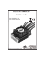
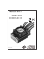
Bedienungsanleitung
brushless + brushed
GM - GENIUS 90 Best.-Nr. 7164
GM - GENIUS 120 Best.-Nr. 7168
Änderungen vorbehalten! Keine Haftung für Druckfehler!
PN.MD-01
5 Herzlichen Glückwunsch zum Kauf des wohl weltweit besten und vielseitigsten Wettbewerbsreglers für
Bürsten- und Bürstenlose Motoren von Graupner/GM-Racing. Dabei können bürstenlose Motoren mit
und ohne Hallsensoren verwendet werden. Der Regler ist aber auch ohne Hallsensoren so feinfühlig,
dass Marc Fischer das 1. A-Finale bei der Europameisterschaft in Türkheim sogar bei Regen unter
schwersten Bedingungen gewinnen konnte. Mit diesem Regler setzt Entwicklungschef Ralf Helbing die
Reihe seiner erfolgreichen Fahrtenregler fort, mit denen schon zahlreiche Welt- und
Europameisterschaften, sowie nationale Titel gewonnen wurden. Die Genius Regler setzen erneut
Maßstäbe in der Funktionalität, Regelverhalten und Programmierung.
5 Deutscher Meister EGTWSC und PRO10 2007, BRCATourenwagen Meister 2007 in England
Wichtiger Hinweis:
Bitte lesen Sie diese Anleitung vor Gebrauch Ihres Reglers sorgfältig durch. Nur so nutzen Sie das
gesamte Potential Ihres Reglers und vermeiden Fehler bei der Bedienung. Geben Sie die
Bedienungsanleitung weiter, falls Sie Ihren Regler weiterverkaufen.
Beschreibung:
GM-Racing Regler sind mit den neuesten Bauteilen bestückt. Besonderer Wert wird hierbei auf
Funktionalität, Lebensdauer, Stand der Technik, Design und Bauteilgröße gelegt.
Die von unserem Team ständig weiter entwickelte Software garantiert in erster Linie präzise und
einfache Einstellungen. Das „Easy-Set-System” und das „IDA-System“ ermöglicht Ihnen das Einstellen
jeder Funktion innerhalb von Sekunden. Mit Hilfe eines Programmers #2894.12 oder eines PCs mit
USB-Schnittstelle (und Windows 2000, XP, Vista) lassen sich Zusatzfunktionen einfach einstellen.
Mittels weniger Schritte passen Sie Ihren Regler und damit maßgeblich das Verhalten Ihres Modells den
Gegebenheiten an.
Dabei lässt sich der Regler aber auch schon ohne jede Programmierung im Auslieferzustand sofort
einsetzen.
Der Regler ist im Auslieferzustand sowohl für Ni-MH, Ni-Cd geeignet.
Der Regler erkennt im Modus 3 (Modus für LiPo/NiMH) die Spannung des Antriebsakkus nach dem
Einstecken des Fahrakkus automatisch und regelt dann bei Unterschreiten der zulässigen Spannung
von 50/80 der Anfangsspannung die Leistung automatisch ab. Vorraussetzung dafür ist ein
ausbalancierter Akkupack, bei dem die Zellen die gleiche Kapazität haben.
Weiterhin erkennt der Regler beim Einstecken automatisch, ob ein Bürstenmotor oder ein Bürstenloser
Motor (mit oder ohne Sensoren) angeschlossen wurde.
Achtung! Bei Verwendung von Bürstenmotoren in der Motorkonfiguration #3 und #4 für möglichen
Rückwärtsgang dürfen max. 7,4V Akkus angeschlossen werden.
Programmierbare Hauptfunktionen:
-Modus 0 (vorwärts mit Bremse) auch für LiPo, Flugmodelle mit sanften Anlauf und Bremse Softgas 16
-Modus 1 (vorwärts mit Bremse) für NiMH, für max. Leistung für MODIFIED Klassen, 4-5 Zellen (8kHz)
-Modus 2 (vorwärts mit Bremse) für NiMH, für Strecken mit normalen Griff (Werkseinstellung) (8kHz)
-Modus 3 (vorwärts mit Bremse) für LiPo-Akkus und NiMH-Akkus für Strecken mit wenig Griff (4kHz)
-Modus 4 (vorwärts mit Bremse und rückwärts) für LiPo-Zellen und NiMH-Akkus (8kHz)
Rückwärtsfahrt durch Vollbremse aktivieren
-Modus 5 (vorwärts mit Bremse und rückwärts) für NiMH-Akkus (8kHz)
Rückwärtsfahrt durch Vollbremse oder Motorstilltand im Neutralpunkt aktivieren
Modi für die SPORT-Klasse mit Sensoranschluss und variablem Motortiming:
-Modus 6 (vorwärts mit Bremse) für NiMH mit normalen Griff (8kHz)
-Modus 7 (vorwärts mit Bremse) für NiMH mit wenig Griff (8kHz)
-Modus 8 (vorwärts mit Bremse) für LiPo und NiMH für sehr wenig Griff, 20% AUTOBRK. (4kHz)
Genaue Beschreibung der Hauptfunktionen ab Seite 9 und der Zusatzfunktionen siehe ab Seite 15.
Sonstige Funktionen:
- Auslesen der maximalen Drehzahl, des Maximalstromes, Anzeige der maximalen Geschwindigkeit
- programmierbare Spannungsüberwachung (oder automatisch)
- starkes BEC-System
- Digitale Leistungsanpassung
- Wiederaufladen des Fahrakkus beim Bremsen
- USB-Adapter mit LED zur einfachen Programmierung aller Zusatzfunktionen mit dem PC
- Kundenspezifische Modusprogrammierung aller 9 Modi möglich
- einfachste Programmierung der Modi 0-8 mit Hilfe der SET-Tast, der LEDs und des Senders
- Übertemperaturabschaltung
2
Programmierbare Zusatzfunktionen:
#1 Ein-/Ausschaltfunktion mit Taster für den Regler, Speicherung der Fahrdaten
#2 Automatikbremse
#3 Bremse Maximum
#4 Vollbremse
#5 Maximale Rückwärtsfahrt
#6 ABS
#7 Automatikgas
#8 Softanlauf
#9 Timing
(nur mit bürstenlosen Motoren)
#10 Drehzahlbegrenzung
(nur mit bürstenlosen Motoren)
#11 Strombegrenzung
#12 Startstrombegrenzung
#13 Turbo
#14 Powerkurve
#15 Bremse Minimum
#16 Reserviert, Einstellungen für Temperaturabschaltung, Sensormodus, Bremsmodi, Motortyp
#17 Frequenz
#18 Reserved1, Konfiguration für Datentransfer, Sendermodusprogrammierung, Pieptöne
#19 Softbremse
#20 Vollgaspunkt
#21 Nullpunkt
#22 Vollbremsepunkt
#23 Nullpunktbreite
#24 Modus
#25 Programmnummer
#26 Unterspannungsabregelung
#27 maximale Anlaufleistung (PWM-Breite) ohne Sensor
#28 maximaler Anlaufstrom ohne Sensor
Inhaltsverzeichnis:
Warnhinweise...................................................................................................................... 4
Einbau des Reglers.............................................................................................................. 5
Anschluss des Reglers an den Empfänger.......................................................................... 5
Anschluss eines bürstenlosen Motors (Motorkonfiguration #1)........................................... 6
Anschluss eines Bürstenmotors für die Funktionen vorwärts/Motor aus/(Bremse) (#2)...... 7
Anschluss eines Bürstenmotors für die Funktionen vorwärts/Motor aus/Bremse/rückwärts (#3) 7
Anschluss eines Bürstenmotors für die Funktionen vorwärts/Motor aus/Bremse/rückwärts (#4) 7
Einstellen des Reglers auf die Senderwege, Programmierung der Hauptfunktionen......... 8-10
Zurücksetzen der Zusatzfunktionen auf die Werkseinstellung............................................ 8-10
Programmierung des Modus 0-8.......................................................................................... 8-10
Aktivieren des Rückwärtsgangs/Vorwärtsgangs................................................................... 11
Zusatzfunktionen................................................................................................................... 11-17
IDA-System: Einstellen der Werte mit dem PC.................................................................... 18
Fehlermeldungen................................................................................................................. 19
Technische Daten................................................................................................................ 19
Zubehör............................................................................................................................... 19
Kurzanleitung...................................................................................................................... 20-21
CE-Konformitätserklärung, Hinweise zum Umweltschutz................................................... 22
Servicestellen...................................................................................................................... 23
3
Warnhinweise:
- Dass CE-Zertifikat des Reglers entbindet nicht der Verpflichtung, äußerste Vorsicht zu wahren.
- Sollte der Motor einmal nicht wie gewünscht anlaufen oder bei einem Absturz stellen Sie den
Senderknüppel sofort auf Motorposition aus, um eine Überlastung des Reglers zu vermeiden. Stellen
Sie die Drehzahlbegrenzung auf 20 = 120000U/min oder niedriger und wählen Sie einen softeren Anlauf
für einen besseren und sauberen Anlauf.
- Benutzen Sie nur Motoren von GM-Racing oder Graupner, die für den verwendeten
Spannungsbereich vorgesehen sind!
- Verwenden Sie nur Hochleistungsakkus von GM-Racing oder Graupner. Akkus mit einem zu
hohen Innenwiderstand können zur Zerstörung des Reglers führen!
- Lassen Sie Ihr RC-Modell niemals unbeaufsichtigt, solange ein Akku angesteckt ist. Im Falle eines
Defektes, könnte dies Feuer am Modell oder seiner Umgebung verursachen.
- Der Fahrtenregler oder andere elektronische Komponenten dürfen niemals mit Wasser in Berührung
kommen. Der Fahrtenregler ist vor Staub, Schmutz, Feuchtigkeit, Vibration und anderen Fremdteilen zu
schützen.
- Solange der Motor an den Regler angeschlossen ist, dürfen Sie niemals den Motor mit einem
separaten Akku laufen lassen. Dies zerstört den Regler und führt zum Verlust der Garantie.
- Verpolen Sie Ihren Regler nicht. Benutzen Sie verpolsichere Stecksysteme. Vermeiden Sie
Kurzschlüsse und blockierende Motoren.
- Alle Kabel und Verbindungen sollen gut isoliert sein. Kurzschlüsse können zur Zerstörung Ihres
Reglers führen.
- Nicht für Kinder unter 14Jahren, kein Spielzeug!
- Die Regler sind ausschließlich für den Einsatz in Batterie- bzw. Akkubetriebenen, funkferngesteuerten
Modellen vorgesehen, ein anderweitiger Betrieb ist nicht zulässig. Der Gebrauch in einem Modell zur
Personenbeförderung ist verboten!
- Motoren, Getriebe, Schiffs- oder Luftschrauben sind gefährliche Gegenstände. Halten Sie sich daher
niemals neben oder vor dem Gefährdungsbereich des Antriebes auf!
- Technische Defekte mechanischer oder elektronischer Teile können zum unverhofften Anlaufen des
Motors und herumfliegenden Teilen führen, die erhebliche Verletzungen verursachen können.
- Führen Sie immer zuerst einen Reichweitetest am Boden durch (halten Sie dabei Ihr Modell fest),
bevor Ihr Modell zum Einsatz kommt.
- Es dürfen keinerlei Veränderungen am Regler durchgeführt werden, es sei denn, diese sind in der
Anleitung beschrieben.
- Haftungsausschluss: Sowohl die Einhaltung der Montage- und Bedienungsanleitung, als auch die
Bedingungen und Methoden bei Installation, Betrieb, Verwendung und Wartung des Fahrtenreglers
können von der Fa. GM-Racing oder Fa. Graupner nicht überwacht werden. Daher übernimmt die Fa.
GM-Racing oder die Fa. Graupner keinerlei Haftung für Verluste, Schäden oder Kosten, die sich aus
fehlerhafter Verwendung und Betrieb ergeben, oder in irgendeiner Weise damit zusammenhängen.
- Es dürfen nur von uns empfohlene Komponenten und Zubehörteile verwendet werden. Verwenden Sie
nur zueinander passende, Original GM-Racing oder GRAUPNER - Steckverbindungen und
Zubehörteile.
- Vergewissern Sie sich vor jeder Inbetriebnahme bevor Sie den Fahrtenregler einstecken, dass: Ihr
Sender als einziger auf der Frequenz Ihres Empfängers sendet und Ihr Sender eingeschaltet ist und der
Gashebel auf der Position STOP steht.
4
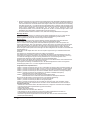
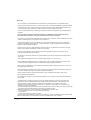
Einbau des Reglers ins Modell:
Nachdem Sie den Regler ausgepackt haben, überlegen Sie sich bitte, an welcher Stelle des Modells
Sie diesen am besten platzieren wollen. Beachten Sie dabei bitte, dass der Regler so gut wie möglich
gekühlt wird und dass der Empfänger sowie die Empfangsantenne möglichst mehr als 3cm Abstand
zum Fahrtenregler, sowie den dicken, stromführenden Kabeln sowie dem Akku haben soll. Nachdem
Sie sich für eine geeignete Stelle entschieden haben, fixieren Sie bitte den Regler so mit zwei Streifen
doppelseitigem Klebeband, dass die Kühlfläche gut gekühlt wird oder höchstens um 30% vermindert
wird.
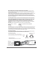
Anschluss des Reglers an den Empfänger:
Ihr Regler ist werkseitig mit einem Graupner/JR-Stecker bestückt. Dieser passt sowohl bei
Graupner/JR- als auch bei Futaba und KO (ab 1995)-Empfängern. Bei anderen Empfängern
erkundigen Sie sich bitte nach der richtigen Polarität.
rot
=
schwarz oder braun=
weiß oder orange =
Empfänger plus
Empfänger minus
Impulsleitung
Stecken Sie den Stecker des Empfängerkabels in den gewünschten Servosteckplatz
(bei Automodellen Steckplatz 2) Ihres Empfängers.
Bevor Sie den Fahrakku anschließen, schalten Sie den Sender ein und stellen den Gashebel auf die
Position „Motor aus“ und schließen Sie den Motor wie anfolgend beschrieben an!
5
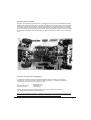
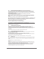
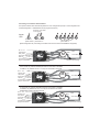
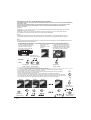
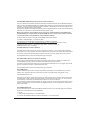
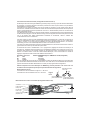
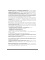
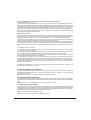
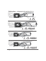
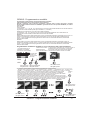
Anschluss eines bürstenlosen Motors (Motorkonfiguration #1):
Benutzen Sie nur Motoren von Graupner oder GM-Racing, die für den verwendeten Spannungsbereich
vorgesehen sind! Motoren anderer Fabrikate könnten zu einem schlechten Anlauf führen und im
schlimmsten Fall den Regler zerstören.
Verbinden/Verlöten Sie die drei Motoranschlüsse des Reglers mit den drei Anschlüssen des Motors.
Sollte Ihr Motor falsch herum laufen, so vertauschen Sie zwei Anschlüsse des Motors. Vertauschen Sie
niemals die Anschlüsse am Akku! Vertauschen Sie niemals Anschlüsse bei Motoren mit Hallsensoren!
Die Motor- und Akkuanschlusskabel sollten niemals länger als 12cm und möglichst gleich lang sein. Je
länger die Anschlusskabel sind, um so schwerer wird Ihr Modell und um so mehr Störungen strahlen die
Kabel ab. Sind die Akkuanschlusskabel länger als 20cm, so muss alle 10cm ein entsprechender
Powerkondensator angelötet werden.
Bei IFMAR/EFRA GM EVO2 IFMAR SPEC Motoren mit Hallsensoren stecken Sie nun den Stecker
der Hallsensoren in den Adapter #2894.9 und diesen in den Regler ein. (rot = 3V, schwarz = GND,
andere Farben = Sensoren 1-3). Bei Verwendung der GM SPORT/PRO/EVO 3 Motoren oder
LRP/Reedy-Motoren verwenden Sie sich das entsprechende Adapterkabel #2894.4 oder #2894.8, falls
gewünscht.
Ansonsten müssen die Hallsensoren nicht unbedingt angeschlossen sein. Der Motor läuft dann
sensorlos.
Bei Programmierung der Funktion “RESERVED” auf den Wert 6 (Werkseinstellung) oder 2 wird
mit dieser Software der Motor bei angeschlossenen Hallsensoren ausschließlich mit
Hallsensoren angesteuert. Die Hallsensoren werden daher nicht eingemessen! Der richtige
Anschluss der Motorkabel ist daher zwingend, da sonst der Regler zerstört werden kann. Für
IFMAR Motoren mit Kunststoffgebundenen Neodymmagneten wir dieser Modus empfohlen.
Der Motor muss nach den Kabelfarben richtig angeschlossen werden.
Regler
verbinden mit
IFMAR/EFRA Motor (z. B. GM #97213-97293, Reedy/LRP)
A = blau
A = blau
B= gelb
B = gelb
C= orange
C = orange
Bei angeschlossenen Hallsensoren zeigen die LEDs die Position zweier Hallsensoren an und
funktionieren nicht wie später in der Anleitung beschrieben. Es empfiehlt sich daher zur
Programmierung des Reglers die Hallsensoren vor dem Anschließen der Stromversorgungen
abzustecken.
Anschluss eines Hochleistungsakkus von Graupner oder GM-Racing:
Verbinden Sie das rote Akkuanschlusskabel mit dem Fahrakku +.
Verbinden Sie das schwarze Akkuanschlusskabel mit dem Fahrakku -.
Je nach Modus 0-8
kurze Pieptöne
TÖNE
red ge
rot
LED
rote LED an,
gelbe LED aus
red ge
rot
...
...
red ge
rot
rote LED blinkt,
gelbe LED an
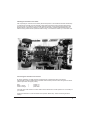
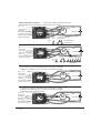
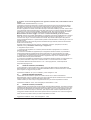
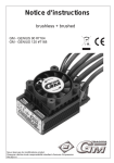
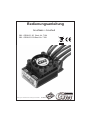
Anschluss eines bürstenlosen Motors (Motorkonfiguration #1)
Lüfter: 5 - 6 V
schwarz
Programmierstecker und
Stecker für Hallsensoren
blau
6
M
C
B
A
Motor
-
orange
gelb
+
Empfängerkabel
LED gelb
SET-Taste (EIN-/AUS)
LED rot
Antriebsakku
+
rote Schrumpfschlauchmarkierung
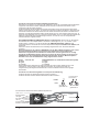
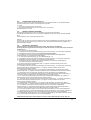
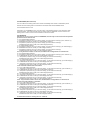
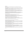
Anschluss eines Bürstenmotors:
Der Regler erkennt beim Einschalten des Reglers die Art der Motorverkabelung (außer
Motorkonfiguration #4. In dieser muss die Reserviert-Einstellung auf 64 programmiert werden.
Je nach Modus 0-8
kurze Pieptöne
TÖNE
LED
red ge
rot
rote LED an,
gelbe LED an
red ge
rot
...
...
red ge
rot
red ge
rot
red ge
rot
red ge
rot
red ge
rot
red ge
rot
red ge
rot
rote LED blinkt 6x,
gelbe LED an
rote LED blinkt,
gelbe LED an
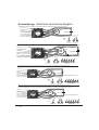
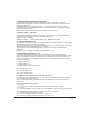
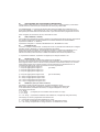
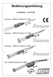
(Motorkonfiguration #2) Anschluss eines Bürstenmotors für die Funktionen vorwärts/Motor aus/(Bremse)
(Doppelter Dauerstrom zugelassen!)
Lüfter: 5 - 6 V
schwarz
Programmierstecker und
Stecker für Hallsensoren
blau
-
Motor
M
-
orange
gelb
+
+
Empfängerkabel
LED gelb
SET-Taste (EIN-/AUS)
LED rot
Antriebsakku
+
rote Schrumpfschlauchmarkierung
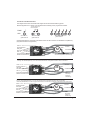
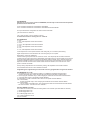
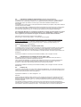
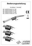
(Motorkonfiguration #3) Anschluss eines Bürstenmotors für die Funktionen vorwärts/Motor aus/(Bremse)/rückwärts
Achtung: max. Betriebsspannung 7,4V! Nur der Halbe Dauerstrom ist zugelassen! Modus 4 oder 5 verwenden!
Lüfter: 5 - 6 V
schwarz
Programmierstecker und
Stecker für Hallsensoren
blau
+
M
-
Motor
-
orange
gelb
+
Empfängerkabel
LED gelb
SET-Taste (EIN-/AUS)
LED rot
Antriebsakku
+
rote
Schrumpfschlauchmarkierung
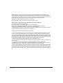
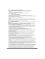
(Motorkonfiguration #4) Anschluss eines Bürstenmotors für die Funktionen vorwärts/Motor aus/(Bremse)/rückwärts
Achtung: max. Betriebsspannung 7,4V! Nur 2/3 des Dauerstroms zugelassen! Modus 4 oder 5 verwenden!
Reserviert (RESERVED) muss auf 64 programmiert werden, da ansonsten vom Regler ein Brushless Motor erkannt wird!
Lüfter: 5 - 6 V
schwarz
Programmierstecker und
Stecker für Hallsensoren
blau
+
M
-
Motor
-
orange
gelb
+
Empfängerkabel
LED gelb
SET-Taste (EIN-/AUS)
LED rot
Antriebsakku
+
rote
Schrumpfschlauchmarkierung
7
Einstellung des Reglers auf die Senderwege, Programmierung der Hauptfunktionen,
Zurücksetzen der Zusatzfunktionen auf die Werkseinstellungen:
Damit der Regler richtig funktionieren kann stellen Sie bitte alle Funktionen des Gashebels am
Sender auf “NORMAL” (Futaba und einige andere Fabrikate “REVERSE”) und die Wege auf
100%.
Die Empfängerpulslänge muss bei Vollgas länger sein, als im Neutralpunkt. Diese können Sie
mit der PC-Software für die verschiedenen Senderpositionen auslesen.
Der Regler benutzt den Motor als Lautsprecher für die Pieptöne. Deshalb können Sie die
Pieptöne nur bei angeschlossenem Motor hören. Außerdem geht der Regler in den Fehlermodus,
wenn kein Motor angeschlossen ist, so dass eine Programmierung dann nur mit Hilfe des USBAdapters #7168.6 möglich ist.
Bei angeschlossenen Hallsensoren zeigen die LEDs die Position zweier Hallsensoren an und
funktionieren nicht wie später in der Anleitung beschrieben. Es empfiehlt sich daher zur
Programmierung des Reglers die Hallsensoren vor dem Anschließen der Stromversorgungen
abzustecken. Geübte Programmierer können den Regler aber auch nur mit Hilfe der Pieptöne
programmieren.
Der Regler hat voreingestellte Knüppelwege. Die Werkseinstellung ist auf den Modus 2 (vorwärts mit
Bremse) für normale Strecken eingestellt.
Mit diesem Modus lassen sich erst einmal alle Modelle mit NiMH-Akkus oder 2 LiPo-Zellen betreiben.
Damit der Motor aktiviert wird, muss zuerst der Senderhebel auf die Position „Motor aus oder
Bremse“ gebracht werden. Ansonsten läuft der Motor aus Sicherheitsgelbden nicht an.
Sollte der Motor in der Gasstellung bremsen und in der Bremsstellung anlaufen, dann programmieren
Sie bitte den Senderknüppel auf „Reverse“ (Futaba)!
Bei richtiger Einstellung der Senderwege leuchtet:
- die rote und die gelbe LED in der Knüppelposition „Motor aus/Neutralstellung“
- die gelbe LED im „Gasregelbereich“
- die rote LED in der „Vollgasstellung“
- keine LED in dem „Bremsregelbereich“
- die rote LED in der „Vollbremsestellung“
Einstellung des Reglers auf die genauen Senderwege und Voreinstellung der Zusatzfunktionen
auf bestimmte Streckenverhältnisse (Modus 0-8):
Die genauen Einstellungen entnehmen Sie bitte mit Hilfe des PC-Programms.
Bemerkung: Zur Optimierung des Fahrverhaltens können die Werkseinstellungen von den aufgeführten
Daten abweichen. Zur Überprüfung der Werkseinstellung muss der Regler mit Hilfe des Programmers
#2894.12, eines GMVIS-Commanders #94401 oder mit Hilfe eines PC mit dem USB-Adapter #7168.6
ausgelesen werden.
8
Einstellung des Reglers auf die Senderwege, Programmierung der Hauptfunktionen,
Zurücksetzen der Zusatzfunktionen auf die Werkseinstellungen:
Damit der Regler richtig funktionieren kann stellen Sie bitte alle Funktionen des Gashebels am
Sender auf “NORMAL” (Futaba und einige andere Fabrikate “REVERSE”) und die Wege auf
100%.
Die Empfängerpulslänge muss bei Vollgas länger sein, als im Neutralpunkt. Diese können Sie
mit der PC-Software für die verschiedenen Senderpositionen auslesen.
Werkseinstellungen ohne Gewähr, bitte in PC-Software überprüfen:
-Modus 0 (vorwärts mit Bremse) für LiPo/NiMH-Akkus für PRO10, Strecken mit wenig Griff,
Flugmodelle: Softanlauf: soft = 16, Timing 30°, MAXREVERSE = 100 d.h., RESERVED = 2 (LiPo
Abregelspannung, normale Bremssoftware), FREQUENCY=0 (8kHz), Strombegrenzung = 200A,
Startstrombegrenzung = 120A, Automatikbremse = 0%, Bremse Min. = 20%, Bremse Max. = 100%
Modus 1-4 mit neuer Bremssoftware für präziseres Bremsen in Wettbewerben:
-Modus 1 (vorwärts mit Bremse) für NiMH-Akkus für Strecken mit maximalen Griff, optimal für 4-5
Zellen für maximale Leistung
Werkseinstellung: Timing 30°, MAXREVERSE = 100 d.h. ca. 4V Abregelspannung, RESERVED = 22
(ca. 4V Abregelspannung), FREQUENCY=1 (8kHz+LIM), Strombegrenzung = 250A,
Startstrombegrenzung =120A, Automatikbremse = 0%, Bremse Minimum = 20%, Bremse Maximum =
100%
-Modus 2 (vorwärts mit Bremse) für NiMH-Akkus für Strecken mit normalen Griff, neue
Bremssoftware
Werkseinstellung: Timing 30°, MAXREVERSE = 100, RESERVED = 22 (neue Bremssoftware, ca. 4V
Abregelspannung), FREQUENCY=1 (8kHz+LIM), Strombegrenzung = 200A, Startstrombegrenzung =
120A, Automatikbremse = 0%, Bremse Min. = 20%, Bremse Max. = 100%
-Modus 3 (vorwärts mit Bremse) für LiPo-Akkus und NiMH-Akkus für Strecken mit wenig Griff
Werkseinstellung: Timing 30°, MAXREVERSE =100, RESERVED = 18 d.h. LiPo-Erkennung an,
FREQUENCY=9 (4kHz+LIM), Strombegrenzung = 150A, Startstrombegrenzung = 120A,
Automatikbremse = 0%, Bremse Minimum = 20%, Bremse Maximum = 100%, Vollbremse = 100%
Modi mit Rückwärtsgang:
-Modus 4 (vorwärts mit Bremse und rückwärts) für NiMH-Akkus oder LiPo-Zellen
Aktivierung des Rückwärtsgang durch durch Vollbremse bei Motorstillstand.
Werkseinstellung: Timing 30°, MAXREVERSE = 100, RESERVED = 18 (LiPo-Erkennung an),
FREQUENCY=1 (8kHz+LIM), Strombegrenzung = 150A, Startstrombegrenzung = 120A,
Automatikbremse = 0%, Bremse Minimum = 20%, Bremse Maximum = 100%
-Modus 5 (vorwärts mit Bremse und rückwärts) für NiMH-Akkus für Strecken mit maximalen Griff,
Aktivierung des Rückwärtsgang bei Motorstillstand im Neutralpunkt oder durch Vollbremse.
Werkseinstellung: Timing 30°, MAXREVERSE = 100, RESERVED = 6 (normale Bremssoftware),
FREQUENCY=1 (8kHz+LIM), Strombegrenzung = 200A, Startstrombegrenzung = 120A,
Automatikbremse = 0%, Bremse Minimum = 20%, Bremse Maximum = 100%
Modi für die Sportklasse mit SPORT-Motoren mit variablen Timing mit Hallsensoren:
-Modus 6 (vorwärts mit Bremse) für NiMH-Akkus für Strecken mit gutem Griff
Werkseinstellung: Timing ohne Sensoren 30°, MAXREVERSE =100, RESERVED = 22(4V Abregelspg.),
FREQUENCY=1 (8kHz+LIM), Strombegrenzung = 200A, Startstrombegr. = 120A, Automatikbremse =
0%, Bremse Minimum = 20%, Bremse Maximum = 100%, Vollbremse = 100%
(Variables Timing mit Sensoren + 0°/+15°)
-Modus 7 (vorwärts mit Bremse) für NiMH-Akkus für Strecken mit wenig Griff
Werkseinstellung: Timing ohne Sensoren 30°, MAXREVERSE =100, RESERVED = 6 (4V Abregelspg.),
FREQUENCY=1 (8kHz+LIM), Strombegrenzung = 150A, Startstrombegrenzung = 120A,
Automatikbremse = 0%, Bremse Minimum = 20%, Bremse Maximum = 100%, Vollbremse = 100%
(Variables Timing + 0°/+30°)
-Modus 8 (vorwärts mit Bremse) für NiMH-Akkus oder LiPo-Zellen für Strecken mit sehr wenig
Griff + Automatikbremse
Werkseinstellung: Timing ohne Sensoren 30°, MAXREVERSE =100, RESERVED = 2 (LiPo-Erkennung
an), FREQUENCY=9 (4kHz+LIM), Strombegrenzung = 120A, Startstrombegrenzung = 120A,
Automatikbremse = 20%, Bremse Minimum = 20%, Bremse Maximum = 100%, Vollbremse = 100%
(Timing mit Sensoren hohes Timing + 0°/15°)
Einstellung des Reglers auf die genauen Senderwege und Voreinstellung der Zusatzfunktionen
auf bestimmte Streckenverhältnisse (Modus 0-8):
Die genauen Einstellungen entnehmen Sie bitte mit Hilfe des PC-Programms.
9
Programmierung des Modellmodus 0 - 8 mit der SET-Taste und dem Sender
Alle Einstellungen können auch mit dem PC durchgeführt werden!
Damit der Regler richtig funktionieren kann stellen Sie bitte alle Funktionen des Gashebels am
Sender auf “NORMAL” (Futaba und einige andere Fabrikate “REVERSE”) und die Wege auf 100%.
Besonderheiten: alle Modi:
Wenn Reserviert1 = 0, 4, 8,12, 128, 132, 136 oder 140 dann werden die Senderwege bei der
Modusprogrammierung übernommen. (Außer Mode 0 und Mode 1, siehe unten!)
Senderwege Programmierung deaktivieren:
Wenn Reserviert1 = 130, 134, 138 oder 142, dann werden die Senderwege bei der
Modusprogrammierung nicht einlernt und statt dessen aus dem Modusspeicher gelesen.
Modus 0:
Im Modus 0 kann nur die Senderposition für den Neutralpunkt übernommen werden. Der Vollgaspunkt
und Vollbremsepunkt werden vom vorherigen Modus, oder bei deaktivierter Senderwege
Programmierung aus dem Modusspeicher übernommen.
Modus 1:
Im Modus 1 können nur die Senderwege für Vollgas und Neutralpunkt übernommen werden. Der
Vollbremsepunkt wird vom vorherigen Modus, oder bei deaktivierter Senderwege Programmierung aus
dem Modusspeicher übernommen.
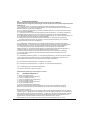
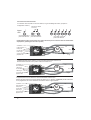
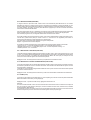
Programmierung Modus 0-8: (Modus 4 + 5 mit Rückwärtsfahrt, alle anderen vorwärts/Bremse)
2. Senderknüppel
auf die gewünschte
Neutralposition
stellen
1. Sender und dann Regler
einschalten/einstecken
(Motor muss
angeschlossen sein)
3. SET-Taste für ca. 4s drücken bis die rote LED
leuchtet und ein langer Piepton ertönt.
Nach dem Piepton leuchtet die gelbe LED und die
Senderwege und die Modi können programmiert werden.
Je nach Modus 0-8
kurze Pieptöne
TÖNE
LED
red ge
rot
red ge
rot
rote LED an,
gelbe LED an
...
...
“Neutral=Motor aus”
red ge
rot
red ge
rot
rote LED an,
gelbe LED aus
rote LED blinkt,
gelbe LED an
5. Durch das verändern der Hebelposition geben Sie nun den Modus wie folgt vor,
- auf Neutral belassen = Modus 0, einmal ‘Vollgas’ = Modus 1, einmal ‘Vollgas’ - ‘Vollbremse’ = Modus 2,
einmal ‘Vollgas’ - ‘Vollbremse’ - ‘Vollgas’ = Modus 3 usw. Für jede Hebelbewegung haben Sie ca. 4 Sekunden
Zeit. Sollte der Modus 1 erst bei Vollbremse bestätigt werden, so müssen Sie den Gasweg am Sender auf
‘REVERSE’ stellen. Bei jedem Wechsel des Modus leuchtet jeweils die andere LED und die Pieptöne für
den aktuell gewählten Modus ertönen. Die letzte Position halten oder auf Neutralposition zurück gehen.
(Wenn Sie einen Werksreset durchführen wollen, dann drücken Sie jetzt erneut die SET-Taste,
bis die nächsten Pieptöne 3x kurz und 1x lang für den Werksreset ertönen.)
Nun erlöschen beide LEDs und nach einem langen Piepton bei roter LED an ertönen die Piepstöne für
die Bestätigung für den gewünschten Modus zum zweiten Mal. Der Regler ist jetzt wieder fahrbereit.
Modus 0
Modus 1
Modus 2
Modus3
ca. 4s
Pause
red ge
rot
Modus x
red ge
rot
rote LED an,
gelbe LED an
“Neutral=Motor aus”
“Vollgas”
red ge
rot
red ge
rot
rote LED aus,
gelbe LED an
10
“Vollbremse”
“Vollgas”
“Voll ...”
red ge
rot
red ge
rot
red ge
rot
0-8x
red ge
rot
rote LED blinkt,
gelbe LED an
Aktivieren/Einlegen des Rückwärtsgangs (Mode 4 + 5)
Im Modellmodus 4+5 haben Sie sowohl eine voll proportionale Bremse als auch einen voll
proportionalen Rückwärtsgang. Um rückwärts fahren zu können gehen Sie mit dem Senderknüppel auf
die Position „Vollbremse“ und bleiben dort, bis das Fahrzeug steht und dann noch für etwa 1s länger.
Danach bringen Sie den Senderknüppel in die „Neutralstellung/Nullpunkt“. Der Rückwärtsgang ist nun
eingelegt. Sie können nun proportional rückwärts fahren, in dem Sie den Senderknüppel in
Bremsrichtung bewegen.
Im Modus 5 werden beim Betrieb eines bürstenlosen Motors ohne Hallsensoren zusätzlich beide
Fahrtrichtungen ermöglicht/aktiviert, sobald sich der Senderknüppel in der ”Neutralstellung/Nullpunkt”
befindet und der Motor steht, wenn AUTOGAS und AUTOBRAKE auf 0 programmiert sind.
Aktivieren/Einlegen des Vorwärtsgangs
Natürlich können Sie auch bei der Rückwärtsfahrt das Fahrzeug proportional abbremsen, indem Sie
den Senderknüppel in Gasrichtung bewegen.
Um nach der Rückwärtsfahrt wieder vorwärts fahren zu können gehen Sie mit dem Senderknüppel auf
die Position „Vollgas“ um das Fahrzeug abzubremsen und den Vorwärtsgang wieder aktivieren zu
können und bleiben dort, bis das Fahrzeug steht. Danach bringen Sie den Senderknüppel in die
„Neutralstellung/Nullpunkt“. Der Vorwärtsgang ist nun wieder aktiviert/eingelegt. Sie können nun wieder
vorwärts fahren, in dem Sie den Senderknüppel in Gasrichtung bewegen.
Im Modus 5 werden beim Betrieb eines bürstenlosen Motors ohne Hallsensoren zusätzlich beide
Fahrtrichtungen ermöglicht/aktiviert, sobald sich der Senderknüppel in der ”Neutralstellung/Nullpunkt”
befindet und der Motor steht, wenn AUTOGAS und AUTOBRAKE auf 0 programmiert sind.
Zusatzfunktionen:
Die Zusatzfunktionen lassen mit einem PC mit USB-Schnittstelle und Windows 2000, XP oder Vista
einstellen. Mit Hilfe des Programmers #2894.12 lassen sich die Funktionen 1-17 programmieren.
Folgende Zusatzfunktionen sind verfügbar:
#1 Ein-/Ausschaltfunktion mit Taster für den Regler, Speicherung der Fahrdaten
#2 Automatikbremse
#3 Bremse Maximum
#4 Vollbremse
#5 Maximale Rückwärtsfahrt
#6 ABS
#7 Automatikgas
#8 Softanlauf
#9 Timing
(nur mit bürstenlosen Motoren)
#10 Drehzahlbegrenzung
(nur mit bürstenlosen Motoren)
#11 Strombegrenzung
#12 Startstrombegrenzung
#13 Turbo
#14 Powerkurve
#15 Bremse Minimum
#16 Reserviert, Einstellungen für Temperaturabschaltung, Sensormodus, Bremsmodi, Motortyp
#17 Frequenz
Nur mit der PC-Software mit USB-adapter programmierbar:
#18 Reserved1, Konfiguration für Datentransfer, Sendermodusprogrammierung,Pieptöne
#19 Softbremse
#20 Vollgaspunkt
#21 Nullpunkt
#22 Vollbremsepunkt
#23 Nullpunktbreite
#24 Modus
#25 Programmnummer
#26 Unterspannungsabregelung
#27 maximale Anlaufleistung (PWM-Breite) ohne Sensor
#28 maximaler Anlaufstrom ohne Sensor
11
#1
Ein- /Ausschaltfunktion mit Taster für den Regler, Speicherung der Fahrdaten
REGLER EIN/AUS (0,1,2,4,5,6)
Der Regler kann so programmiert werden, dass er sich samt dem BEC-System über die SET-Taste Einund Ausschalten lässt. Außerdem kann er so programmiert werden, dass er auch über den Sender
ausgeschaltet werden kann, indem man mindestens 16s auf die Position „Vollbremse“ geht.
Wenn sich der Regler einschaltet, gibt er je nach gewähltem Modellmodus 0-8 kurze Pieptöne aus und
die rote LED blinkt dabei (gelbe LED an), um den Modellmodus und das Einschalten des Reglers zu
bestätigen. Bei Anschluss eines Bürstenmotors gibt der Regler nach einer kurzen Pause weitere 6
kurze Pieptöne aus, die rote LED blinkt dabei und die gelbe LED ist dabei an.
Speicherung der Fahrdaten: Die maximale Drehzahl und der maximale Strom wird im EEPROM
gespeichert, wenn der Regler über die Taste oder 16s Vollbremse ausgeschaltet wird. Dazu muss der
entsprechende Wert 1, 2, 4, 5 oder 6 programmiert sein.
Die max. Drehzahl, der maximale Strom und die Geschwindigkeit wird nach dem Auslesen der Daten
mit dem PC angezeigt. Die Leerlaufdrehzahl und der maximale Topspeed lässt sich so leicht ermitteln.
Sollte die Drehzahl deutlich zu hoch angezeigt werden, so lag während des Laufes ein Timingfehler vor.
Sie sollten durch Veränderung der Parameter (Frequenz, Softanlauf, AMPLIMIT, Timing und
Drehzahlbegrenzung = 8 oder 13) versuchen die Timingfehler zu verhindern.
0 = Regler immer an
1 = Regler nach kurzem Tastendruck an und nach erneutem kurzen Tastendruck aus
2 = Regler nach einstecken des Fahrakkus sofort an, aber mit kurzem Tastendruck aus-/ einschaltbar.
Danach wieder über Taste einschaltbar.
4 = Regler nach 16s Vollbremse aus oder kurzen Tastendruck aus
5 = Regler nach kurzem Tastendruck an, nach 16s Vollbremse oder kurzem Tastendruck ausschaltbar
6 = Regler nach einstecken des Fahrakkus sofort an, aber mit kurzem Tastendruck oder nach 16s
Vollbremse aus. Danach wieder über Taste einschaltbar
Ist der SWITCH-Wert beim Auslesen = 64 + dem programmierten Wert, so wurde die
Abschalttemperatur überschritten.
#2
AUTOMATIKBREMSE (AUTOBRAKE)
Die Automatikbremse ist von 0-100% einstellbar und wirkt bereits bei Neutralstellung des Gashebels.
Sie ist unabhängig von der minimalen und maximalen Bremswirkung einstellbar und erlaubt daher ein
engeres Kurvenfahren.
Werkseinstellung: 0% (10% im Modus 3), empfohlene Werte 0 - 20%
#3
MAXIMALE BREMSE (BRAKEMAX)
Die maximale Bremswirkung ist die, die bis ca. 95% des Bremshebelweges wirkt, also solange die rote
LED noch nicht leuchtet. Mit dieser Funktion lässt sich ein Überbremsen/Blockieren der Räder
verhindern.
Die maximale Bremswirkung im Regelbereich ist von 0-100% einstellbar.
Werkseinstellung: 100%, empfohlene Werte für Autos 70-100%
#4
VOLLBREMSE (FULLBRAKE)
Die Bremswirkung in der Gashebelposition ‘Vollbremse’ lässt sich getrennt von der maximalen Bremse
einstellen. Die rote LED leuchtet in der Position ‘Vollbremse’. Dies ist besonders im Off-Road
gewünscht, wo in den Kurven ein guter Bremsregelbereich gewünscht wird, bei Sprüngen für die
Flugbahnkorrektur jedoch die volle Bremswirkung benötigt wird. Weiterhin ist diese Funktion für eine
„Notbremse“ sinnvoll.
Die „Vollbremse“ Funktion ist ebenfalls von 0-100% einstellbar.
Werkseinstellung: 100%, empfohlene Werte 70-100%
12
#5
MAXIMALE RÜCKWÄRTSFAHRT (MAXREVERSE)
Die Maximale Rückwärtsfahrt lässt sich zwischen 0-100% einstellen. Damit lässt sich in Rennbooten
oder auch für RC Cars die maximale Rückwärtsfahrt begrenzen.
Ist MAXREVERSE = 0, so wird auch in den Modellmodi 1-3 die Unterspannungsabregelung für NiMH
von 4V auf 3V reduziert, außer es wird im Menü Unterspannungsabregelung ein anderer Wert als 250
programmiert. Dann gilt die in diesem Menü eingestellte Unerspannungsabregelung.
empfohlene Werte für Rennboote 20-50%, Autos 50-100%
#6
ABS (0=AUS, 1=EIN)
Die ABS Bremse verhindert das Ausbrechen des Fahrzeuges beim Bremsen. Die ABS-Bremse taktet
zwischen vom Gashebel vorgegebenen max. Bremswert und dem BRKMIN Wert.
Werkseinstellung: 0 = AUS,
Empfohlene Einstellungen: 1= EIN, BRAKEMIN 20-40%, BRAKEMAX 70-100%
#7
AUTOGAS (0-100)
„Standgas“ in der Senderposition „Neutralstellung/Nullpunkt“, ist besonders in Standardklassen sinnvoll,
wo ein besseres rollen des Fahrzeuges erwünscht ist.
Nach einigen Sekunden wird das „AUTOGAS“ deaktiviert, um am Start einen Frühstart durch ein
losrollendes Fahrzeug zu vermeiden und um bei längeren Standzeiten Strom zu sparen.
Damit das AUTOGAS funktioniert, muss die AUTOMATIKBREMSE auf 0% eingestellt sein!
0 = Werkseinstellung, empfohlen Einstellungen für Standardklassen 1-20
#8
SOFTANLAUF (0 - 200)
Je kleiner der eingestellte Wert, um so sanfter schaltet der Regler durch.
Sollte Ihr Motor nicht wie gewünscht anlaufen, oder in einer bestimmten Drehzahl zu früh „hängen
bleiben“, dann schalten Sie den Motor sofort wieder aus und reduzieren Sie den Wert (bzw. erhöhen Sie
die Hochlaufzeit), bis der Motor sauber anläuft und hochdreht. Mit den Werkseinstellung laufen in der
Regel alle Motoren sauber an.
1 = Hochlaufzeit 4s
2 = Hochlaufzeit 2s
3 = Hochlaufzeit 1,33s
4 = Hochlaufzeit 1s (für Motorsegler)
...
16 = Hochlaufzeit 0,22s (für Kunstflug)
...
50 = Hochlaufzeit 80ms
100 = Hochlaufzeit 40ms
200 = Hochlaufzeit 20ms
#9
TIMING (0-4) (nur mit bürstenlosen Motoren!)
Um den maximalen Wirkungsgrad zu erreichen, kann das Timing eingestellt werden.
In den meisten Fällen hat die Werkseinstellung den besten Wirkungsgrad.
Bei problematischen Motoranlauf empfiehlt es sich 30° Timing zu wählen.
Für sensorlosen Betrieb:
0 = 0° Timing
1 = 7,5° Timing
(empfohlen für slottless stator brushless Motoren mit 2 Polen)
2 = 15° Timing
3, 4 = 30° Timing (Werkseinstellung im Modus 0-8, empfohlen für alle anderen Motoren)
Für Sensor Betrieb nur mit PC programmierbar:
0,1 = wie mechanisch am Motor eingestelltes Timing
2 =+15° Timing, wie mechanisch am Motor eingestelltes Timing +15°
3, 4 =+30° Timing, wie mechanisch am Motor eingestelltes Timing +30°
13
#10
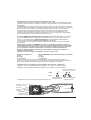
DREHZAHLBEGRENZUNG (RPMLIMIT) (nur mit bürstenlosen Motoren!)
Die maximale Drehzahl kann begrenzt werden. Dies eignet sich besonders für Standardklassen um
eine Einheitliche Drehzahl mit einer vorgeschriebenen Getriebeuntersetzung und damit die gleiche
Endgeschwindigkeit zu erreichen oder um bei Flugmodellen die Drehzahl auf eine maximale Drehzahl
der Luftschraube zu begrenzen.
Die Drehzahlbegrenzung eignet sich auch besonders für Einsteiger um die maximale
Endgeschwindigkeit des Modells zu begrenzen.
Mit dem Programmer #2894.12/GMVIS-Commander kann die Drehzahlbegrenzung bei zweipoligen
Motoren zwischen 12 500 U/min und 210 000 U/min in 200 Stufen eingestellt werden, siehe Formel,
Grafik!
Mit Hilfe des PC-Programms wird die eingestellte Drehzahl direkt angezeigt.
Bei problematischen Motoranlauf empfiehlt es sich die Motordrehzahl auf 8 = 125000U/min (2-Pol
Motor) oder niedriger als 13 = 100000U/min zu programmieren, da dann der Regler durch eine
jeweils andere Software für einen besseren Anlauf sorgen kann!
Bei mehr als 2-poligen Motoren entspricht die Drehzahl:
Drehzahl = angegebene Drehzahl * 2 / Polzahl des Magneten
Formeln für die maximale Drehzahl (U/min) bei Einstellung mit dem GMVIS-Commander/Programmer:
max. Drehzahl ca. = 5 000 000 / {(Eingestellter Wert +12) * Polzahl des Motors}
eingestellter Wert ca. = {5 000 000 / (max. Drehzahl * Polzahl des Motors)} - 12
ROAR-Sportsman = 92 = 24 000U/min
#11
STROMBEGRENZUNG (AMP LIMIT)
Die Strombegrenzung kann mit Hilfe des Porgrammers #2894.12 von 0-200A, mit Hilfe des PCProgramms von 0-250A eingestellt werden. 0= Strombegrenzung deaktiviert. Durch die
Strombegrenzung kann das Drehmoment des Motors beeinflusst werden. Die Strombegrenzung sollte
so eingestellt werden, dass z. B. beim Automodell die Räder beim Anfahren nicht oder nur leicht
durchdrehen.
Werkseinstellung: 80-250A (je nach Modus), empfohlene Werte 40-200A
#12
STARTSTROMBEGRENZUNG (START LIMIT)
Die Startstrombegrenzung ist aktiviert, wenn sich der Gashebel für mind. 5 Sekunden in der Position
„Neutralstellung/Nullpunkt“ befindet.
Sie ist wieder deaktiviert, wenn das erst mal die Position „Vollgas“ erreicht wurde.
Der Startstrom sollte so gewählt werden, dass die Räder nicht oder nur leicht durchdrehen, damit am
Start die maximale Traktion umgesetzt werden kann.
Werkseinstellung: 60-200A (je nach Modus), empfohlene Werte 40 - 200A, je nach Griff
#13
TURBO (0-9A)
Die Turbofunktion erhöht bei Vollgas innerhalb eines Zeitintervalls von 4ms den möglichen Stromfluss
um den eingestellten Wert in A, beginnend mit dem Strom der eingestellten Strombegrenzung. (siehe
Grafik!)
Werkseinstellung:1A, empfohlene Einstellung 0 - 5A
Beispiel:
Sie haben die Strombegrenzung auf 50A eingestellt. Damit stehen Ihnen zu jeder Zeit mind. 50A zur
Verfügung. In dem Moment, in dem Sie „Vollgas“ geben, setzt der Turbo ein. D. h. dass nun alle 4ms
der Strom um den eingestellten Wert bis zum maximalen Strom erhöht wird.
Dies optimiert die Traktion insbesondere auf rutschigen Strecken und spart Strom und erhöht den
Topspeed auf der Geraden. Die Turbofunktion ist jedes Mal aktiviert, wenn Sie den Gashebel in
„Neutralstellung/Nullpunkt“ bringen und dann „Vollgas“ geben.
14
#14
POWERKURVE (POWERCURVE) (0-2)
Mit dieser Funktion können drei verschiedene Gaskurven gewählt werden um das Regelverhalten
optimal auf die Strecke und den Fahrstil anpassen zu können.
0 = linear
1 = soft (ähnlich wie exponential am Sender)
2 = hart für Standardklassen (ähnlich wie exponential + am Sender)
Werkseinstellung: 0 = linear
#15
MINIMALE BREMSE (BRAKEMIN)
Die Minimale Bremswirkung ist die, die unmittelbar nach dem Nullpunkt ansteht.
Die ABS-Bremse taktet zwischen vom Gashebel vorgegebenen max. Bremswert und dem BRKMIN
Wert.
Werkseinstellung: 20%, empfohlene Werte 0-50%
Beispiel:
Wenn Sie die min. Bremse auf 30% einstellen, dann stehen beim Betätigen der Bremse sofort 30% an.
Der Bremsbereich des Hebels ist somit zwischen 30% und maximaler Bremswirkung aufgeteilt und
damit feinfühliger regelbar.
#16
RESERVIERT (RESERVED)
Einstellungen für Temperaturschutz, Sensormodus, Bremsmodi und Motortyp
Achtung! Bei allen ungeraden Einstellungen erlischt die Garantie, da dann der Temperaturschutz
deaktiviert ist!
0 = LiPo-Unterspannungsabregelung
1 = Temperaturschutz aus (bei dieser Einstellung erlischt die Garantie!) , LiPo-Unterspg.-abregelung
2 = IFMAR/EFRA Hallsensorbetrieb, LiPo- Unterspannungsabregelung
3 = Temperaturschutz aus (bei dieser Einstellung erlischt die Garantie!) und IFMAR/EFRA
Hallsensorbetrieb, LiPo-Unterspannungsabregelung
4 = 4V Unterspannungsabregelung (3V, wenn MAXREVERSE = 0)
5 = Temperaturschutz aus (bei dieser Einstellung erlischt die Garantie!) , 4V Unterspg.-abregelung
6 = IFMAR/EFRA Hallsensorbetrieb, 4V Unterspannungsabregelung
7 = Temperaturschutz aus, IFMAR/EFRA Hallsensorbetrieb, 4V Unterspannungsabregelung
(bei dieser Einstellung erlischt die Garantie!)
8 = brushless Motor Modus (Motorkonfiguration 1) vorgeben! In diesem Modus können keine
Bürstenmotoren betrieben werden!
9 = Temperaturschutz aus (bei dieser Einstellung erlischt die Garantie!) , LiPo-Unterspg.-abregelung,
brushless Motor Modus (Motorkonfiguration 1) vorgeben! In diesem Modus können keine
Bürstenmotoren betrieben werden!
10 = IFMAR/EFRA Hallsensorbetrieb, LiPo-Unterspannungsabregelung, brushless Motor Modus
(Motorkonfiguration 1) vorgeben! In diesem Modus können keine Bürstenmotoren betrieben werden!
11 = Temperaturschutz aus (bei dieser Einstellung erlischt die Garantie!) und IFMAR/EFRA
Hallsensorbetrieb, LiPo-Unterspannungsabregelung, brushless Motor Modus (Motorkonfiguration 1)
vorgeben! In diesem Modus können keine Bürstenmotoren betrieben werden!
12 = 4V Unterspannungsabregelung, brushless Motor Modus (Motorkonfiguration 1) vorgeben! In
diesem Modus können keine Bürstenmotoren betrieben werden!
13 = Temperaturschutz aus (bei dieser Einstellung erlischt die Garantie!) , 4V Unterspg.-abregelung,
brushless Motor Modus (Motorkonfiguration 1) vorgeben! In diesem Modus können keine
Bürstenmotoren betrieben werden!
14 = IFMAR/EFRA Hallsensorbetrieb, 4V Unterspannungsabregelung, brushless Motor Modus
(Motorkonfiguration 1) vorgeben! In diesem Modus können keine Bürstenmotoren betrieben werden!
15 = Temperaturschutz aus (bei dieser Einstellung erlischt die Garantie!), IFMAR/EFRA
Hallsensorbetrieb, 4V Unterspannungsabregelung, brushless Motor Modus (Motorkonfiguration 1)
vorgeben! In diesem Modus können keine Bürstenmotoren betrieben werden!
16 = neue Bremssoftware aktiviert, für ein besseres Bremsverhalten bei hohen Geschwindigkeiten
17 = Temperaturschutz aus (bei dieser Einstellung erlischt die Garantie!) , LiPo-Unterspg.-abregelung,
neue Bremssoftware aktiviert, für ein besseres Bremsverhalten bei hohen Geschwindigkeiten
18 = IFMAR/EFRA Hallsensorbetrieb, LiPo-Unterspannungsabregelung, neue Bremssoftware aktiviert,
für ein besseres Bremsverhalten bei hohen Geschwindigkeiten
Empfohlene Einstellung im Tourenwagen: 6 oder 22, weitere Einstellungen auf der Seite 18!
15
#16
RESERVIERT (RESERVED)
Einstellungen für Temperaturschutz, Sensormodus, Bremsmodi und Motortyp
Achtung! Bei allen ungeraden Einstellungen erlischt die Garantie, da dann der Temperaturschutz
deaktiviert ist!
19 = Temperaturschutz aus (bei dieser Einstellung erlischt die Garantie!) und IFMAR/EFRA
Hallsensorbetrieb, LiPo-Unterspannungsabregelung, neue Bremssoftware aktiviert, für ein besseres
Bremsverhalten bei hohen Geschwindigkeiten
20 = 4V Unterspannungsabregelung, neue Bremssoftware aktiviert, für ein besseres Bremsverhalten
bei hohen Geschwindigkeiten
21 = Temperaturschutz aus (bei dieser Einstellung erlischt die Garantie!) , 4V Unterspg.-abregelung,
neue Bremssoftware aktiviert, für ein besseres Bremsverhalten bei hohen Geschwindigkeiten
22 = IFMAR/EFRA Hallsensorbetrieb, 4V Unterspannungsabregelung, neue Bremssoftware aktiviert, für
ein besseres Bremsverhalten bei hohen Geschwindigkeiten
23 = Temperaturschutz aus, IFMAR/EFRA Hallsensorbetrieb, 4V Unterspannungsabregelung
(bei dieser Einstellung erlischt die Garantie!), neue Bremssoftware aktiviert, für ein besseres
Bremsverhalten bei hohen Geschwindigkeiten
....
30 = IFMAR/EFRA Hallsensorbetrieb, 4V Unterspannungsabregelung, brushless Motor Modus
(Motorkonfiguration 1) vorgeben! In diesem Modus können keine Bürstenmotoren betrieben werden!,
neue Bremssoftware aktiviert, für ein besseres Bremsverhalten bei hohen Geschwindigkeiten
31 = Temperaturschutz aus (bei dieser Einstellung erlischt die Garantie!), IFMAR/EFRA
Hallsensorbetrieb, 4V Unterspannungsabregelung, brushless Motor Modus (Motorkonfiguration 1)
vorgeben! In diesem Modus können keine Bürstenmotoren betrieben werden!,
neue Bremssoftware aktiviert, für ein besseres Bremsverhalten bei hohen Geschwindigkeiten
32 = spezielle Bremssoftware für die Automatikbremse (besseres Bremsverhalten bei hohen
Geschwindigkeiten)
....
54 = IFMAR/EFRA Hallsensorbetrieb, 4V Unterspannungsabregelung, neue Bremssoftware aktiviert,
für ein besseres Bremsverhalten bei hohen Geschwindigkeiten, spezielle Bremssoftware für die
Automatikbremse (besseres Bremsverhalten bei hohen Geschwindigkeiten)
....
64 = Bürstenmotor Motorkonfiguration 4 vorgeben!, LiPo-Modus
....
68 = Bürstenmotor Motorkonfiguration 4 vorgeben!, 4V Unterspannungsabregelung
....
128 = Strombegrenzung für die Bremse deaktivieren
....
128+ andere Funktionen...siehe PC-Software
Empfohlene Einstellung im Tourenwagen: 6 oder 22
#17
FREQUENZ (FREQUENCY)
0 = 8kHz mit regelbarer PWM
1 = 8kHz mit regelbarer Strombegrenzung
2 = 16kHz mit regelbarer PWM
3 = 16kHz mit regelbarer Strombegrenzung
4 = 2kHz mit regelbarer PWM
5 = 2kHz mit regelbarer Strombegrenzung
8 = 4kHz mit regelbarer PWM
9 = 4kHz mit regelbarer Strombegrenzung
Bei niedrigeren Frequenzen bleibt der Regler kühler und die Leistungsentfaltung ist weicher.
Bei hohen Frequenzen läuft der Motor effizienter und es steht mehr Leistung zur Verfügung.
Neu und bisher unerreicht.
Anstelle der Pulsbreite wird der Strom geregelt. Dadurch bleibt das Regelverhalten über die gesamte
Laufdauer gleich, unabhängig von der Akkuspannung. Dies ermöglicht von Beginn bis zum Ende einer
Akkuentladung annähernd gleiche Rundenzeiten, vor allem aber das gleiche Regelverhalten. Mit Hilfe
der Gaskurve und der Strombegrenzung kann das Regelverhalten optimal an das Modell und die
Gegebenheiten angepasst werden und das bei max. Motorleistung bei „Vollgas“.
Werkseinstellung: je nach Modus, empfohlene Werte für die Strombegrenzung: 60 - 250A
16
Programmieren der erweiterten Zusatzfunktionen, die mit der PC-Software programmierbar sind:
#18 RESERVED1 (0 -142) Konfiguration Datentransfer, Sendermodusprogrammierung, Pieptöne
0 = Daten #1-#17 senden (für Programmer #2894.12 oder GMVIS-Commander V2005 und neuer)
Senderwege bei Modusprogrammierung am Regler mit SET-Taste und Sender übernehmen
2 = Senderwege bei Modusprogrammierung am Regler mit SET-Taste und Sender nicht übernehmen,
die Senderwege werden aus dem EEPROM-Speicher gelesen,
Daten #1-#17 senden (für Programmer #2894.12 oder GMVIS-Commander V2005 und neuer)
4 = langer Piepton nach dem Einschalten deaktivieren
8= kurze Moduspieptöne nach dem Einschalten deaktivieren
128 =
alle Daten senden,
Senderwege bei Modusprogrammierung am Regler mit SET-Taste und Sender übernehmen
130 = Senderwege bei Modusprogrammierung am Regler mit SET-Taste und Sender nicht übernehmen,
die Senderwege werden aus dem EEPROM-Speicher gelesen, alle Daten senden.
...128+ andere Funktionen...siehe PC-Software!
#19 SOFTBREMSE (0 - 200)
Je kleiner der eingestellte Wert, um so sanfter bremst der Regler. (Werte siehe auch SOFTGAS/2)
1 = Bremse Hochlaufzeit 2s, 2 = Bremse Hochlaufzeit 1s
... 100 = Bremse Hochlaufzeit 20ms, 200 = Bremse Hochlaufzeit 10ms
#20 Vollgaspunkt
Die Einstellung des Vollgaspunktes in ms erfolgt normalerweise über die MODE 1-8 Programmierung
(wenn RESERVED=0 oder 128), kann aber auch über den PC programmiert und verändert werden. Der
Vollgaspunkt muss mindestens um 1600 oder 0.1ms größer als der Nullpunkt eingestellt werden.
#21 Nullpunkt
Die Einstellung des Nullpunktes in ms erfolgt normalerweise über die MODE 1-8 Programmierung
(wenn RESERVED=0 oder 128), kann aber auch über den PC programmiert und verändert werden. Der
Nullpunkt muss mindestens um 1600 oder 0.1ms größer als der Vollbremsepunkt eingestellt werden.
#22 Vollbremsepunkt
Die Einstellung des Vollbremsepunktes in ms erfolgt normalerweise über die MODE 1-8
Programmierung (wenn RESERVED=0 oder 128), kann aber auch über den PC programmiert und
verändert werden.
#23 Nullpunktbreite
Die Nullpunktbreite kann individuell eingestellt werden. Dies kann z. B. notwendig sein, wenn der
Senderknüppel zu viel Spiel hat. In diesem Fall muss die Nullpunktbreite vergrößert werden.
#24 MODUS
0-3, 6-8 Modus für Vorwärtsfahrt/Nullpunkt/Bremse
Achtung! Beim Einstellen der Modi mit dem PC müssen die Akkusorten manuell eingestellt werden!
4, 5 Modus für Vorwärts/Nullpunkt/Bremse/Rückwärts
#25 PROGRAMMNUMMER
Am PC kann jeder Einstellung pro Modus 0-8 eine Programmnummer vergeben werden, so dass das
Abspeichern und Wiederfinden von bestimmten Einstellungen/Dateien erleichtert wird.
#26 Unterspannungsabregelung
Die Unterspannungsabregelung kann in V programmiert werden, siehe PC-Software.
Damit lässt sich besonders für Li-Akkus, aber auch für NiMH-Akkus die Unterspannungsabregelung in
sehr feinen Schritten einstellen.
Ist der Wert auf 250 programmiert, so ist diese Funktion deaktiviert und es wird die Einstellung in der
RESERVED-Einstellung und MAXREVERSE-Einstellung übernommen.
#27 maximale Anlaufleistung (PWM-Breite) ohne Sensor
Die max. Anlaufleistung (PWM Pulsbreite) bei stehendem Motor ohne Sensor kann so gewählt werden,
dass der Motor möglichst ruckfrei anläuft. Beginnen Sie mit möglichst kleinen Werten und steigern Sie
die Einstellung, bis der Motor gut anläuft. Werkseinstellung (128)
Zu hohe Werte können den Regler zerstören, falls der Motor nicht sofort anläuft.
#28 maximaler Anlaufstrom ohne Sensor
Der Anlaufstrom bei stehendem Motor ohne Sensor kann so gewählt werden, dass der Motor möglichst
ruckfrei anläuft (10-50A). Sobald der Motor angelaufen ist, wird der Strom, der in der
Startstrombegrenzung (START AMP) bzw. Strombegrenzung(AMP LIMIT) eingestellt ist zugelassen.
Werkseinstellung (30A). Zu hohe Werte können den Regler zerstören, falls der Motor nicht sofort
anläuft.
17
#0
IDA-System Einstellen der Werte mit dem PC (mit USB und Windows 2000 , XP, Vista):
Mit Hilfe des IDA-Systems können mit dem PC mit der Software die Daten des Reglers wahlweise
ausgelesen und/oder programmiert werden. Den USB-Treiber und die Reglerprogrammiersoftware (AS
Genius Tool) können Sie bei www.gm-racing.de im Download-Bereich oder www.graupner.de
herunterladen. Installieren Sie zuerst den USB-Treiber und dann die PC-Software.
Wählen Sie im Programm die gewünschte Schnittstelle aus.
Mit der Maus können Sie die gewünschten Einstellwerte einstellen.
0
IDA-System mit USB-Schnittstelle Daten senden und empfangen mit dem PC:
(keine zusätzliche Spannungsquelle nötig!)
Stecken Sie den Genius Regler von der Spannungsversorgung aus.
Laden Sie sich den entsprechenden USB-Treiber für die Best.-Nr. 7186.6 herunter und installieren Sie
diesen.
Stecken Sie den USB-Adapter Best.-Nr. 7168.6 in einen freien USB-Steckplatz.
Starten Sie nach dem installieren der PC-Software das Programm AS Genius Tool, aktualisieren Sie die
Ports (COM), klicken Sie den verwendeten Port an und aktivieren Sie diesen.
Übertragen der Reglerdaten von und zum PC:
1.) Wenn Sie mit der Maus auf “Daten holen”, so wechselt die PC-Software auf “Warte auf Daten” und
die Daten des Genius Reglers können wie folgt ausgelesen werden:
2.) Stecken Sie den 8-poligen Schnittstellenstecker in den entsprechenden Steckplatz am Regler.
Nach kurzer Zeit leuchtet die gelbe LED und zeigt den Start des IDA-Programms an.
Sollte die gelbe LED nach einigen Sekunden immer noch nicht leuchten, dann drücken Sie die SETTaste am Regler und halten diese gedrückt. Drücken Sie gleichzeitig die RESET-Taste am USB-Adapter
kurz und halten die SET-Taste am Regler so lange, bis die gelbe LED aufleuchtet.
3.) Nach kurzer Zeit erlischt die gelbe LED und die Daten werden gesendet.
4.) Nachdem der Regler die Daten gesendet hat, leuchtet die LED gelb. Der Genius Regler wartet nun
auf Daten.
5.) Zur Datenübertragung der Daten vom PC klicken Sie nun auf “Daten senden”.
6.) Ansonsten, wenn Sie die Daten aus dem Regler nur auslesen möchten und diesen nicht mit dem
PC programmieren möchten, so so stecken Sie einfach den Schnittstellenstecker am Regler ab.
7.) Nach dem Empfang der Daten vom PC leuchtet die rote LED. Nach dem entfernen des Datenkabels
ist beim nächsten anschließen der Spannungsquelle der Fahrtenregler wieder fahrbereit. Wenn die
Tasterfunktion als Schalter aktiviert wurde und die Funktion Schalter an nicht gewählt wurde, dann
müssen Sie bei der nächsten Benutzung den Taster drücken, damit der Regler angeschaltet ist.
18
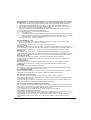
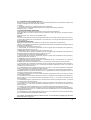
Fehlermeldungen:
1.)
1s
3x
1s
3x
red ge
rot
1s
3x
red ge
rot
rote LED blinkt 3x, rote LED blinkt 3x, rote LED blinkt 3x,
gelbe LED aus
gelbe LED aus
gelbe LED aus
3x
red ge
rot
rote LED blinkt 3x,
gelbe LED aus
1s
1s
1s
3x
red ge
rot
3x
red ge
rot
rote LED blinkt 3x,
gelbe LED aus
red ge
rot
3x
red ge
rot
rote LED blinkt 3x, rote LED blinkt 3x,
gelbe LED aus
gelbe LED aus
Fehlerbeschreibung:
Bei Dauerpiepsen (je 3x kurz ) und/oder Dauerblinken der roten LED (3x kurz) ist beim Anstecken des
Reglers an die Betriebsspannung entweder der Motor falsch oder nicht angeschlossen.
Fehlerbehebung: Motoranschlüsse überprüfen und richtig anschließen.
2.)
1s
red ge
rot
1s
red ge
rot
1s
red ge
rot
1s
red ge
rot
1s
red ge
rot
1s
red ge
rot
1s
red ge
rot
red ge
rot
Fehlerbeschreibung:
Bei Dauerpiepsen (1x lang) und Dauerblinken der roten LED (1x lang) ist die Betriebsspannung zu hoch.
Fehlerbehebung:
Für den Betriebsmodus die richtige Betriebsspannung wählen, indem ein Akku mit der vorgeschriebenen
Zellenzahl verwendet wird.
3.) Fehlerbeschreibung: Der Regler zeigt keinerlei Funktion.
Fehlerbehebung:
Betriebsspannung zu niedrig. Laden Sie den Antriebsakku und überprüfen Sie die Anschlüsse auf eine gute
Verbindung.
Führt dies nicht zum Erfolg, schicken Sie den Regler zur Überprüfung ein.
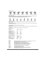
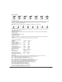
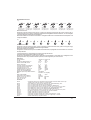
Technische Daten:
Bezeichnung:
Best.-Nr.
Betriebsspannung in V:
Zellenzahl Ni-MH, Ni-Cd:
Zellenzahl LiPo:
Dauerstrom (bürstenlose M.)
Strom kurzzeitig 10s
Impulsstrom bei 25°C
Innenwiderstand bei 20°C ca.
Spannungsabfall @20A ca.
Temperaturabschaltung:
Unterspannungsabregelung:
BEC:
Max. BEC Verlustleistung:
Taktfrequenz:
Abm. in mm mit Kond. ca.:
Gewicht ohne Kabel ca.:
Gewicht mit Kabel ca.:
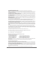
Zubehör:
2894.3
2894.4
2894.5
7168.6
2894.7
2894.8
2894.9
2894.10
2894.12
2894.16
2894.35
91539.10
91539.16
2894.L
Genius 90 Genius 120
7164
7168
4,8-12
4,8-12
4-10
4-10
2-3
2-3
90A
120A
200A
250A
600A
800A
0,0005
0,0004
0,01V
0,008V
ja
ja
einstellbar
5,8V/kurzz. 4A (alle)
2,5W
2,5W
2/4/8/16
50x31x27 50x31x27
60g
60g
95g
95g
Optokoppler für Galvanische Trennung mit Empf.-Akku für Genius und andere BEC-Regler
Sensoradapterkabel (GM EVO3, Dr. Speed/LRP/Reedy - Motoren) 10cm
Schnittstellenkabel GM-VIS Commander/Genius
Schnittstellenkabel PC (Windows 2000/XP mit USB)/Genius
Empfängerkabel für Genius 50, 80, 85, 95, 100 (Servokabel) 20cm
Sensoradapterkabel (GM EVO3, Dr. Speed/LRP/Reedy - Motoren) 20cm
Sensoradapterkabel (GM EVO2 IFMAR SPEC/Novak - Motoren)
Empfängerkabel für Genius 50, 80, 85, 95, 100 (Servokabel) 10cm
R/C-Tester und Programmer mit Servotester für GENIUS-Regler
Powerkondensatorplatine 7x 470µF/16V
Powerkondensatorplatine 7x 220µF/35V
Powerkondensatoren 4700µF/10V (3 Stück) bis 6 Zellen empfohlen!
Powerkondensatoren 2200µF/16V (3 Stück) für 4-10 Zellen empfohlen!
30x30x6mm Lüfter für Genius-Regler
19
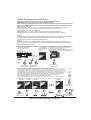
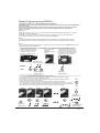
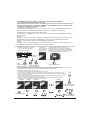
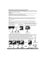
Kurzanleitung: Anschluss des Genius-Reglers:
(Motorkonfiguration #1) Anschluss eines bürstenlosen Motors (Modus 0-8 kann verwendet werden!)
Lüfter: 5 - 6 V
schwarz
Programmierstecker und
Stecker für Hallsensoren
blau
Motor
M
C
B
A
-
orange
gelb
+
Empfängerkabel
LED gelb
SET-Taste (EIN-/AUS)
LED rot
Antriebsakku
+
Je nach Modus 0-8
kurze Pieptöne
rote Schrumpfschlauchmarkierung
TÖNE
LED
red ge
rot
red ge
rot
rote LED an,
gelbe LED an
...
...
red ge
rot
rote LED blinkt,
gelbe LED an
(Motorkonfiguration #2) Anschluss eines Bürstenmotors für die Funktionen vorwärts/Motor aus/(Bremse) (Modus 0-3 oder 6-8 verwenden!)
Lüfter: 5 - 6 V
schwarz
-
M
-
Motor
+
+
orange
gelb
Empfängerkabel
LED gelb
SET-Taste (EIN-/AUS)
LED rot
Antriebsakku
+
Programmierstecker und
Stecker für Hallsensoren
blau
TÖNE
LED
rote Schrumpfschlauchmarkierung
Je nach Modus 0-8
kurze Pieptöne
red ge
rot
red ge
rot
rote LED an,
gelbe LED an
...
...
red ge
rot
red ge
rot
red ge
rot
red ge
rot
red ge
rot
red ge
rot
red ge
rot
rote LED blinkt 6x,
gelbe LED an
rote LED blinkt,
gelbe LED an
(Motorkonfiguration #3) Anschluss eines Bürstenmotors für die Funktionen, vorwärts/Motor aus/(Bremse)/rückwärts
Achtung: max. Betriebsspannung 7,4V! Nur halber Dauerstrom zugelassen! (Modus 4 oder 5 verwenden!)
Lüfter: 5 - 6 V
schwarz
Programmierstecker und
Stecker für Hallsensoren
blau
+
M
-
Motor
-
orange
gelb
+
Empfängerkabel
LED gelb
SET-Taste (EIN-/AUS)
LED rot
Antriebsakku
+
rote Schrumpfschlauchmarkierung
Je nach Modus 0-8
kurze Pieptöne
TÖNE
LED
red ge
rot
red ge
rot
rote LED an,
gelbe LED an
...
...
red ge
rot
red ge
rot
red ge
rot
red ge
rot
red ge
rot
red ge
rot
red ge
rot
rote LED blinkt 6x,
gelbe LED an
rote LED blinkt,
gelbe LED an
(Motorkonfiguration #4) Anschluss eines Bürstenmotors für die Funktionen vorwärts/Motor aus/(Bremse)/rückwärts
Achtung: max. Betriebsspannung 7,4V! Nur 2/3 des Dauerstroms zugelassen! Modus 4 oder 5 verwenden!
Reserviert (RESERVED) muss auf 64 programmiert werden, da ansonsten vom Regler ein Brushless Motor erkannt wird!
Lüfter: 5 - 6 V
schwarz
Programmierstecker und
Stecker für Hallsensoren
blau
+
M
-
Motor
-
orange
gelb
+
Empfängerkabel
LED gelb
SET-Taste (EIN-/AUS)
LED rot
Antriebsakku
+
rote Schrumpfschlauchmarkierung
rot
Je nach Modus 0-8
kurze Pieptöne
TÖNE
LED
red ge
rot
rote LED an,
gelbe LED an
20
red ge
rot
...
...
red ge
rot
rote LED blinkt,
gelbe LED an
red ge
rot
red ge
rot
red ge
rot
red ge
rot
red ge
rot
rote LED blinkt 6x,
gelbe LED an
red ge
rot
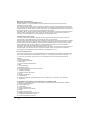
Modus-Programmierung GENIUS:
Programmierung des Modellmodus 0 - 8 mit der SET-Taste und dem Sender
Alle Einstellungen können auch mit dem PC durchgeführt werden!
Damit der Regler richtig funktionieren kann stellen Sie bitte alle Funktionen des Gashebels am
Sender auf “NORMAL” (Futaba und einige andere Fabrikate “REVERSE”) und die Wege auf 100%.
Besonderheiten: alle Modi:
Wenn Reserviert1 = 0, 4, 8,12, 128, 132, 136 oder 140 dann werden die Senderwege bei der
Modusprogrammierung übernommen. (Außer Mode 0 und Mode 1, siehe unten!)
Senderwege Programmierung deaktivieren:
Wenn Reserviert1 = 130, 134, 138 oder 142, dann werden die Senderwege bei der
Modusprogrammierung nicht eingelernt und statt dessen aus dem Modusspeicher gelesen.
Modus 0:
Im Modus 0 kann nur die Senderposition für den Neutralpunkt übernommen werden. Der Vollgaspunkt
und Vollbremsepunkt werden vom vorherigen Modus, oder bei deaktivierter Senderwege
Programmierung aus dem Modusspeicher übernommen.
Modus 1:
Im Modus 1 können nur die Senderwege für Vollgas und Neutralpunkt übernommen werden. Der
Vollbremsepunkt wird vom vorherigen Modus, oder bei deaktivierter Senderwege Programmierung aus
dem Modusspeicher übernommen.
Programmierung Modus 0-8: (Modus 4 + 5 mit Rückwärtsfahrt, alle anderen vorwärts/Bremse)
2. Senderknüppel
auf die gewünschte
Neutralposition
stellen
1. Sender und dann Regler
einschalten/einstecken
(Motor muss
angeschlossen sein)
3. SET-Taste für ca. 4s drücken bis die rote LED
leuchtet und ein langer Piepton ertönt.
Nach dem Piepton leuchtet die gelbe LED und die
Senderwege und die Modi können programmiert werden.
Je nach Modus 0-8
kurze Pieptöne
TÖNE
LED
red ge
rot
red ge
rot
...
...
“Neutral=Motor aus”
red ge
rot
red ge
rot
rote LED an,
gelbe LED aus
rote LED an, rote LED blinkt,
gelbe LED an gelbe LED an
5. Durch das verändern der Hebelposition geben Sie nun den Modus wie folgt vor,
- auf Neutral belassen = Modus 0, einmal ‘Vollgas’ = Modus 1, einmal ‘Vollgas’ - ‘Vollbremse’ = Modus 2,
einmal ‘Vollgas’ - ‘Vollbremse’ - ‘Vollgas’ = Modus 3 usw. Für jede Hebelbewegung haben Sie ca. 4 Sekunden
Zeit. Sollte der Modus 1 erst bei Vollbremse bestätigt werden, so müssen Sie den Gasweg am Sender auf
‘REVERSE’ stellen. Bei jedem Wechsel des Modus leuchtet jeweils die andere LED und die Pieptöne für
den aktuell gewählten Modus ertönen. Die letzte Position halten oder auf Neutralposition zurück gehen.
(Wenn Sie einen Werksreset durchführen wollen, dann drücken Sie jetzt erneut die SET-Taste,
bis die nächsten Pieptöne 3x kurz und 1x lang für den Werksreset ertönen.)
Nun erlöschen beide LEDs und nach einem langen Piepton bei roter LED an ertönen die Piepstöne für
die Bestätigung für den gewünschten Modus zum zweiten Mal. Der Regler ist jetzt wieder fahrbereit.
Modus 0
Modus 1
Modus 2
Modus3
ca. 4s
Pause
red ge
rot
Modus x
red ge
rot
rote LED an,
gelbe LED an
“Neutral=Motor aus”
“Vollgas”
red ge
rot
“Vollbremse”
“Vollgas”
“Voll ...”
red ge
rot
red ge
rot
red ge
rot
red ge
rot
0-8x
rote LED aus,
gelbe LED an
red ge
rot
rote LED blinkt,
gelbe LED an
Modus-Programmierung GENIUS
21
CE-Konformitätserklärung:
EG-Konformitätserklärung
Für das folgend bezeichnete Erzeugnis
GM-GENIUS 90 Best.-Nr. 7164 und GM-Genius 120 Best.-Nr. 7168
wird hiermit bestätigt, dass es den wesentlichen Schutzanforderungen entspricht, die in der Richtlinie des
Rates zur Angleichung der Rechtsvorschriften der Mitgliedstaaten über die elektromagnetische
Verträglichkeit (2004/108/CE) und die Niederspannungsrichtline (LVD) (2006/95/CE) festgelegt sind.
Zur Beurteilung des Erzeugnisses hinsichtlich elektromagnetischer Verträglichkeit wurden folgende Normen
herangezogen:
EN 61000-6-1
EN 61000-6-3
Diese Erklärung wird verantwortlich für den Hersteller/Importeur
Graupner GmbH & Co. KG
Henriettenstr. 94-96
73230 Kirchheim/Teck
abgegeben durch
73230 Kirchheim/Teck, den 12.03.08
Hans Graupner
Geschäftsführer
Hinweise zum Umweltschutz
Das Symbol auf dem Produkt, der Gebrauchsanleitung oder der
Verpackung weist darauf hin, dass dieses Produkt bzw. elektronische Teile
davon am Ende seiner Lebensdauer nicht über den normalen Hausmüll
entsorgt werden dürfen. Es muss an einem Sammelpunkt für das Recycling
von elektrischen und elektronischen Geräten abgegeben werden.
Die Werkstoffe sind gemäß ihrer Kennzeichnung wiederverwertbar. Mit der
Wiederverwendung, der stofflichen Verwertung oder anderen Formen der
Verwertung von Altgeräten leisten Sie einen wichtigen Beitrag zum Umweltschutz.
Batterien und Akkus müssen aus dem Gerät entfernt werden und bei einer
entsprechenden Sammelstelle getrennt entsorgt werden.
Bei RC - Modellen müssen Elektronikteile, wie z.B. Servos, Empfänger oder
Fahrtenregler aus dem Produkt ausgebaut und getrennt bei einer entsprechenden
Sammelstelle als Elektro-Schrott entsorgt werden.
Bitte erkundigen Sie sich bei der Gemeindeverwaltung nach der zuständigen
Entsorgungsstelle.
22
Änderungen sowie Liefermöglichkeit vorbehalten. Für Druckfehler kann keine Haftung übernommen werden.
Garantie kann nur gewährt werden, wenn der verwendete Motor mit eingeschickt wird, eine Fehlerbeschreibung beiliegt und die Getriebeuntersetzung sowie die verwendete Spannungsquelle
benannt wird!
23
24
mesi
meses
mois
Monaten
month
Luxembourg
Kit Flammang
129, route d’Arlon
8009 Strassen
(+35)23 12 23 2
Servicehotline: Tel.: (+49)(01805)472876
Mo-Fr 9.30-11.30 und 13.00-15.00Uhr
Graupner Zentralservice
Graupner GmbH&Co.KG
Postfach 1242
D-73230 Kirchheim/Teck
Tel.: (+49)(07021)722130
Name des Käufers
Owner’s name
Nom de l’acheteur
Straße Wohnort
Übergabedatum
Date of purchase/delivery
Date de remise
La sociéte Graupner GmbH&Co.KG, Henriettenstr. 94-96, 73230 Kirchheim/Teck, Allemagne
accorde sur ce produit une garantie de 24 mois à partir de la date d’achat.
La garantie prend effect uniquement sur les vices de fonctionnement et de matériel du produit
acheté. Les dommages dûs à de l’usure, à de la surcharge, à de mauvais accessoires ou à d’une
application inadaptée, sont exlus de la garantie.
Cette garantie ne remet pas en cause les droits et prétentions légaux du consommateur.
Avant toute réclamation et tout retour du prouit, veuillez s.v.p. Contrôler et noter exactement les
défauts ou vices du produit, car tout autre relatif au produit vous sera facturé.
Belgie/Belgique/Nederland
Jan van Mouwerik
Slot de Houvelaan 30
NL 3155 Maasland VT
(+31) 10 59 13 59 4
Sverige
Baltechno Electronics
Box 5307
S 40227 Göteborg
(+46) 31 70 73 00 0
Ceská Republika/Slovenská Republika
RC Service Z. Hnizdil
Letecka 666/22
CZ 16100 Praha 6 - Ruzyne
(+42) 2 33 31 30 95
Espana
FA - Sol S.A.
C. Avinyo4
E 08240 Maneresa
(+34) 93 87 34 23 4
Italia
GiMax
Via Manzoni, no. 8
I 25064 Gussago
(+39)3 0 25 22 73 2
Schweiz
Graupner Service
Postfach 92
CH 8424 Embrach-Embraport
(+41) 43 26 66 58 3
Servicestellen / Service / Service après-vente
UK
GLIDERS
Brunel Drive
Newark, Nottinghamshire
Graupner GmbH & Co.KG, Henriettenstr. 94-96, 73230 Kirchheim/Teck, Germany guarantees this NG24 2EG
(+44) 16 36 63 05 39
purchase.
of
date
from
product for a period of 24 month
The guarantee applies only to such material or operational defects which are present at the time of
France
purchase of the product.
Damage due to wear, overloading, incompetent handling or the use of incorrect accessories is not Graupner France
Gérald Altmayer
covered by the guarantee.
86, rue ST. Antoine
The user’s legal rights and claims under guarantee are not affected by this guarantee.
57601 Forbach-Oeting
us,
to
item
the
send
or
claim
a
make
you
before
Please check the product carefully for defects
(+33) 3 87 85 62 12
since we are obliged to make a charge for our costs if the product is found to be free of faults.
Die Firma Graupner GmbH& Co. KG, Henriettenstr. 94-96, 73230 Kirchheim/Teck, Deutschland
gewährt ab dem Kaufdatum auf dieses Produkt eine Garantie von 24 Monaten.
Die Garantie gilt nur für die bereits beim Kauf des Produktes vorhandenen Material- oder
Funktionsmängel. Schäden die auf Abnutzung, Überlastung, falsches Zubehör oder
unsachgemäße Behandlung zurückzuführen sind, sind von der Garantie ausgeschlossen.
Die gesetzlichen Rechte und Gewährleistungsansprüche des Verbrauchers werden durch diese
Garantie nicht berührt. Bitte überprüfen Sie vor einer Reklamation oder Rücksendung des Produkt
genau auf Mängel, da wir Ihnen bei Mängelfreiheit die entstandenen Kosten in Rechnung stellen
müssen.
Garanzia di
Garantia de
Garantie de
Garantie von
Warrantied for
Instruction Manual
brushless + brushed
GM - GENIUS 90 #7164
GM - GENIUS 120 #7168
No liability for printing errors. Modifications reserved.
PN.MD-01
5 Congratulations for buying GM-Racing's Genius Controller for conventional and brushless motors,
probably the best and most universal controller for use in contest world-wide. It is adapted for use with
brushless motors with or without Hall sensors. During our tests, however, the controller proved so
sentitive that there appeared to be no need for using the more expensive sensor-equipped motors. Marc
Fischer won the first A-Main at the European Championship 2006 without sensors in wet conditions.
With this controller, Ralf Helbing is extending his series of successful controllers, which won numerous
World and European Championships, as well as national competitions. Genius controllers are again
offering a new challenge in functionality, size, and controlling attitudes.
5 German Champion Touring car modified 2007, BRCA Champion Touring car modified 2007
Important notice:
Please read this manual carefully before using your controller. Only then can you have full profit of the
potential of your controller, and avoid mistakes. Hand the instruction to the next user, in case you sell
the speed controller.
Characteristics:
GM-Racing controllers are packed with the latest components. Functionality, life time, state-of-the-art
features, functional design, and ideal component sizes have been given the greatest consideration. The
software which has been developed and continually improved by our team stands in the first line for
simplicity and precision of the settings. Our “Easy Set System”, in connection with the “IDA System”,
enables you to set each mode within seconds, either with or without the help of the GMVIS Commander
94401 (software version V2005 or later) or the GENIUS-PROGRAMMER 2894.12 or a PC with
Windows 2000, XP, Vista. With a few clicks you will be able to adapt the controller and thus the driving
attitudes of your model to the environment. Still the controller can be used on the spot, without any
programming, in the factory settings.
Factory settings for this controller include its use with both NiMH and NiCD, as well as for two LiPocells.
In mode 3 (Mode for LiPo/NiMH), the controller automatically determines the tension of the drive battery
after plugging it in, and then also automatically slowely shuts down power when the tension drops below
50/80 of the start-up tension, so as to avoid a deep discharge of LiPo / LiIo, or NiMH, and NiCd cells.
One condition for this function is that the battery pack is well-balanced, with every cell having the same
capacity.
Further on the controller automatically determines on plugging-in whether a conventional or a brushless
motor (sensor-equipped or not) has been connected.
Caution! When using a conventional (brush) motor in configuration #3 or #4 to make the reverse gear
available, use only batteries up to 7.4V.
Main programmable functions:
- Mode 0 (forward, with brakes): for LiPo/NiMH-batteries, softgas, softbrake for airplanes, PRO10
- Mode 1 (forward, with brakes): for NiMH-batteries for tracks with maximum grip, optimized for 4-5 cells.
- Mode 2 (forward, with brakes): for NiMH-batteries for tracks with normal grip, with new brake software
- Mode 3 (forward, with brakes): for LiPo-batteries and NiMH-batteries for tracks with low grip.
- Mode 4 (forward with brakes, reverse available): for LiPo/NiMH-batteries
- Mode 5 (forward with brakes, reverse available): for NiMH-batteries
Modes for stock racing with variable timing with hall sensors
- Mode 6 (forward, with brakes): for NiMH-batteries for tracks with good grip
- Mode 7 (forward, with brakes): for NiMH-batteries for tracks with low grip.
- Mode 8 (forward, with brakes): for LiPo-batteries and NiMH-batteries for tracks with very low grip.
For a detailed description of the factory settings see Main functions, pages 9 and following or look at the
PC software.
Other features:
- Reading of the maximum rpm and maximum current, display the maximum speed with PC
- Voltage control
- Powerful BEC system
- Digital power settings adaptation
- Re-charging batteries while breaking
- USB-circuit with LED for easy PC programming of the supplementary functions
- All modes 0-8 are user programmable
- easy setting of the modes 0-8 with Red and green LEDs, SET-Button and the transmitter
- Over-temperature switch-off …
2
Supplementary programmable functions:
The following supplementary functions are available:
#1
#2
#3
#4
#5
#6
#7
#8
#9
#10
#11
#12
#13
#14
#15
#16
#17
#18
#19
#20
#21
#22
#23
#24
#25
#26
#27
#28
On / Off switch function with controller button, save max. rpm and max. current
Automatic brake
Maximum brake
Full brake
Maximum reverse speed
ABS
Automatic throttle
Soft-start
Timing
(brushless motors only)
Speed limiter
(brushless motors only)
Current limiter
Start-up current limiter
Turbo
Power curve
Minimum brake
Reserved, Set-up for temperatur cut-off, Sensormode, Brake modes, motor type
Frequency
Reserved 1, configuration for data transfer, transmitter mode programming, beeps
Soft brake
Full-throttle point
Zero point
Full brake point
Zero point width
Mode
Program number
Low-voltage power-down (Cut-off voltage)
Maximum start-up power (PWM width) without sensor
Maximum start-up current without sensor
Content:
Warnings.............................................................................................................................. 4
Installing the controller in the model..................................................................................... 5
Connecting the controller to the receiverer........................................................................... 5
Connecting a brushless motor to the controller (Motorconfiguration #1).............................. 6
Connecting a brushed motor to the controller (forward/motor stop/brake) #2...................... 7
Connecting a brushed motor (forward/motor stop/brake/reverse) #3................................... 7
Adjusting the controller to the transmitter stick travel, Programming the main functions.... 8-10
Reset the values of the supplementary functions to the factory settings.............................. 8-10
Programming mode #0-8....................................................................................................... 8-10
Activating reverse gear/ forward gear................................................................................... 11
Supplementary functions...................................................................................................... 11-17
IDA-System: Programming the values with the PC............................................................... 18
failure announcement........................................................................................................... 19
Technical specifications....................................................................................................... 19
Accesoires........................................................................................................................... 19
short instruction overview..................................................................................................... 20-21
Service................................................................................................................................. 23
3
Warnings:
- The controller's CE certificate doesn't unbind users from their obligation to use ultimate caution
- Should the motor refuse to start up, or after a crash, then you should immediately set the transmitter's
control stick to the OFF position to avoid any overload to the controller. Set the RPM limitation to 20
= 120.000 RPM or less, and select a softer start-up for a better and smoother start.
- Use only motors delivered by GM-Racing or Graupner which are designed for the intended range of
voltages!
- Use only high performance batteries by Graupner or GM-Racing. Using batteries with an
increased internal resistance may lead to the destruction of the controller!
- Never leave your transmitter unattended when a battery is connected. In case of a deficiency this may
cause an outbreak of fire on the model or its environment.
- Neither the controller nor any other electronic components should ever come in touch with water.
Protect the controller against dust, dirt, humidity, vibrations, or other dangerous elements (with the
exception of water-sealed controllers).
- Never run the motor on a seperate battery while the motor is connected to the controller. This may
destroy the controller, and leads to the loss of our warranty.
- Never mix up polarities. Use plug systems which offer protection against wrong polarity. Avoid
short-circuiting and blocking the motors.
- All cables and connectors should have good insulation. Short-circuits may lead to the destruction of
your motor.
- This product isn't designed for use by children under the age of 14, it isn't a toy!
- GM-controllers are designed for use in battery-driven, radio-controlled models only, any other use
is not permissible. Using this device on a passenger-carrying model is forbidden!
- Motors, gears or gearboxes, and propellers are dangerous objects. Never keep next to or in front of
the danger area of the drive!
- Technical defects or failures of mechanical or electronic parts may lead to an unexpected start-up of
the motor, with parts of it flying off, maybe causing severe injuries.
- Always check the service range of transmission of your model first thing while it's still on the
ground (hold the model tightly!).
- Don't make any changes on the structure and design of your controller unless they are described in
the manual!
- Limited warranty: Graupner Ltd cannot survey the proper application of the mounting and using
regulations, nor the working methods and conditions during the installation, use, operation, and
servicing of the controller. Therefore Graupner Ltd cannot take on any liability for any loss,
damage, or costs resulting from an incorrect use or operation of the product, or connected in any
way with incorrect use or operation.
- Only those components and accessory parts which have been recommended by us may be used. Use
only genuine and matching Graupner connectors and accessory parts.
- Make sure whenever you start connecting and operating the controller, that:
- your transmitter is the only one working on that frequency,
- is switched on,
- and has the throttle set to position “STOP”.
- Use only high-quality batteries by Graupner or GM-Racing. Cheap or old batteries with a high internal
resistance may lead to poor performance or even to the destruction of the controller.
.
4
Installing the controller in the model:
After unpacking the controller think carefully about what position in the model will be ideal. Please keep
in mind that the controller must be optimally cooled, and that both the receiver and the aerial should
have more than 3cm distance to the controller and the thick high-current cables and the battery. After
deciding where to place the controller fix it in place with two strips of double-sided adhesive tape, so
that the cooling surface shows upward for better cooling, or is reduced in surface by no more than 30%.
Connecting the controller to the receiver:
By factory standard, your GM controller is equipped with a Graupner/JR plug which fits into
Graupner/JR as well as Futaba and KO (models 1995 and later) receivers. When using other receivers
please inquire after the proper polarity.
Red
Black or brown
White or orange
=
=
=
receiver (+)
receiver (-)
pulse cable
Insert the plug of the receiver connector cable into the desired servo socket (socket 2 on car models) of
your receiver.
Switch the transmitter on, with the throttle set to position “Motor Stop”, before connecting the drive
battery!
5
Motorconfiguration #1: Connecting a brushless motor to the controller:
Use only motors produced by Graupner or GM-Racing which are designed for the desired voltage
range! Poor quality motors from other sources may lead to bad start-up characteristiques and, in the
worst case, destroy the controller.
Connect the three cables of the controller with the motor by inserting the plug(s) or by soldering the
cables in place. In case the motor turns the wrong way round, swap two connectors on the motor. Never
swap the connectors on the battery! Do not swap the connectors at motors with hall sensors!
The motor and battery connector cables should all be the same length and never longer than 12cm.
The longer the cables, the heavier your model will be, and the more interference will be radioed by
them. If the wires are longer as 20cm, an additional power capacitor must be soldered with right polarity
every 10cm to the battery wire.
On motors with Hall sensors you should now insert the plugs of the sensors into the controller with
one of the adapter wires #2894.4, #2894.8 (GM brushless SPORT/PRO/EVO3/ LRP/Reedy motors) or
#2894.9 (GM brushless EVO2/Novak motors) (red = 3V, black = GND, other colours = sensors 1-3).
If you program “RESERVED” to the value 6(factory setting) or 2 the motor will be commutated
only with the hallsensors, if they are connected. The sensor position will not be read
automatically. The correct connection of the wires is very important, otherwise the speed
controller will be damaged. For IFMAR motors with bonded neodym magnets we recommend
this mode.
The motor must be connected to the same wire colours on the speed controller.
speed controller
A = blue
B = yellow
C = orange
connect to
EFRA motor (f.e. GM #97213-97293, Reedy/LRP)
A = blue
B = yellow
C = orange
When the Hall sensors are connected, the LEDs show the positions of two sensors but don't work in the
way as described later on in this documentation. Therefore we recommend disconnecting the sensors
from the power supply before doing the programming. If you programm your transmitter stick travel with
connected hall sensors, the settings SOFTGAS = 100 = 20ms and rpm limit at approx. 65000rpm will be
set for fast throttle response and to protect the bonded neodym magnets.
Connecting to the battery:
Use only high-quality batteries offered by Graupner Ltd or GM-Racing. Using batteries with an
increased internal resistance may lead to the destruction of the controller!
Connecting to the battery:
depending on the MODE
0-8 short beeps
Connect the red battery cable to the drive battery (+).
Connect the black battery cable to the drive battery (-).
Signal
LED
red ye
rot
red ye
rot
red LED on,
yellow LED off
(Motorconfiguration #1)
Connecting a brushless motor to the controller
6
M
C
B
A
Motor
-
Programming plug and
plug for hall sensors
black
orange
yellow
drive battery
+
blue
red shrink tube marking
+
LED yellow
SET-button (ON-/OFF)
LED red
red ye
rot
red LED flashes,
yellow LED on
fan: 5 - 6 V
receiver wire
...
...
Connecting a conventional brushed motor:
The speed controller does automatically detect the motor configuration (except in motorconfiguration #4.
In Motorconfiguration 4 RESERVED must be programmed to 64!)
depending on the MODE
0-8 short beeps
Signal
LED
red ye
rot
red ye
rot
...
...
red ye
rot
red ye
rot
red ye
rot
red LED on,
red LED flashes,
yellow LED off yellow LED on
red ye
rot
red ye
rot
red ye
rot
red ye
rot
red LED flashes 6x,
yellow LED on
(Motorconfiguration #2): Connecting a brushed motor for the functions forward/Motor stop/(brake)
fan: 5 - 6 V
Programming plug and
plug for hall sensors
-
Motor
M
-
LED yellow
SET-button (ON-/OFF)
LED red
black
orange
yellow
+
drive battery
+
receiver wire
+
blue
red shrink tube marking
(Motorconfiguration #3) Connecting a brushed motor for the functions forward/Motor stop/brake/reverse
In this mode, only half the indicated permanent current drain is available.
In addition, only batteries of max. 7.4V may be connected in this mode!
fan: 5 - 6 V
Programming plug and
plug for hall sensors
-
+
yellow
M
-
Motor
-
LED yellow
SET-button (ON-/OFF)
LED red
black
orange
+
receiver wire
drive battery
+
blue
red shrink tube marking
(Motorconfiguration #4) Connecting a brushed motor for the functions forward/Motor stop/brake/reverse
In this mode, only half the indicated permanent current drain is available.
In addition, only batteries of max. 7.4V may be connected in this mode!
RESERVED must be programmed to 64!
fan: 5 - 6 V
Programming plug and
plug for hall sensors
+
M
-
Motor
-
LED yellow
SET-button (ON-/OFF)
LED red
black
orange
yellow
drive battery
+
receiver wire
+
blue
red shrink tube marking
7
Adjusting the controller to the transmitter stick travel, programming the main functions, setting
the supplementary functions back to their default values:
If the controller is to work properly then all the throttle functions shoud be set to normal (Futaba
“REVERSE”), and travel to 100%.
The receiver puls width must be longer at full throttle compare to the neutral point. The values of
the full throttle, neutral point and full brake position can be checked and adjusted with the PCSoftware.
As the controller uses the motor as a loudspeaker for the beep sounds, you can hear the beeps only
when the motor connector is plugged in. If the motor is not connected, the speedo controller will go into
the error mode.
Programming with the USB-adapter #7168.6 is possible without motor and battery.
When Hall sensors are activated the LEDs show the positions of two Hall sensors and don't work as
described later on in this manual. It is therefore recommended to disconnect the Hall sensors before
connecting the power supply cables. Expert programmers, however, may programme the controller also
without the help of the beeps.
The controller has pre-set stick travels. The factory setting is for model mode #1 (forward with brakes),
and is suitable for all models using the LiPo switch-off. This mode allows for all models to be run with all
sorts of batteries, for a start. In order to initially activate the motor the transmitter stick should be set
to position “motor stop / brake”, or else the motor won't start up for safety reasons. If the motor brakes in
the full throttle position but starts up in the brake position then you should programme the stick to
“reverse”!
The correct settings of the transmitter travels will light these LEDs:
the red and the yellow LED when the stick is in position “motor stop / brake”
the yellow LED in the “throttle control range”
the red LED in the “full throttle range”
no LED in the “brake control range”
the red LED in the “slam brakes” position.
-
8
Adjusting the controller to the transmitter stick travel, programming the main functions, setting
the supplementary functions back to their default values:
If the controller is to work properly then all the throttle functions shoud be set to normal (Futaba
“REVERSE”), and travel to 100%.
The receiver puls width must be longer at full throttle compare to the neutral point. The values of
the full throttle, neutral point and full brake position can be checked and adjusted with the PCSoftware.
Adjusting the controller to the exact transmitter stick travel, and setting the additional functions
presettings to specific track conditions(modes 0-8):
- Mode 0 (forward, with brakes): for LiPo/NiMH-batteries, softgas, softbrake for airplanes, PRO10
factory settings: Timing 30°, MAXREVERSE = 100, RESERVED = 2 (new brake software deactivated,
LiPo cut-off voltage), AMPLIMIT = 200A, STARTAMP = 120A, AUTOBRAKE = 0%, BRAKE MIN = 20%,
BRAKE MAX = 100%
Modes 1-4 with new brake software for softer and more easy braking at races.
- Mode 1 (forward, with brakes): for NiMH-batteries for tracks stock classes and optimized for 4-5 cells.
factory settings: Timing 30°, MAXREVERSE = 100, RESERVED = 22 (new brake software, about 4V
cut-off voltage), FREQUENCY=1, AMPLIMIT = 250A, STARTAMP = 120A, AUTOBRAKE = 0%, BRAKE
MIN = 20%, BRAKE MAX = 100%
- Mode 2 (forward, with brakes): for NiMH-batteries for tracks with normal grip, with new brake software
factory settings: Timing 30°, MAXREVERSE = 100, RESERVED = 22, about 4V cut-off voltage),
FREQUENCY=1, AMPLIMIT = 200A, STARTAMP = 120A, AUTOBRAKE = 0%, BRAKE MIN = 20%,
BRAKE MAX = 100%
- Mode 3 (forward, with brakes): for LiPo-batteries and NiMH-batteries for tracks with low grip.
factory settings: Timing 30°, MAXREVERSE =100, RESERVED = 18 (LiPo cut-off, new brake software),
FREQUENCY=9, AMPLIMIT = 150A, STARTAMP = 100A, AUTOBRAKE = 0%, BRAKE MIN = 20%,
BRAKE MAX = 80%, FULLBRAKE = 100%
- Mode 4 (forward with brakes, reverse available): for NiMH-batteries or LiPo-cells
factory settings: Timing 30°, MAXREVERSE =100%, (LiPo-cut-off deactivated), RESERVED = 18 (about
4V cut-off voltage), FREQUENCY=1, AMPLIMIT = 150A, STARTAMP = 120A, AUTOBRAKE = 0%,
BRAKE MIN = 20%, BRAKE MAX = 100%
- Mode 5 (forward with brakes, reverse available): for NiMH-batteries or two LiPo-cells
factory settings: Timing 30°, MAXREVERSE =100%, RESERVED = 6 (about 4V cut-off voltage, normal
brake software), FREQUENCY=1, AMPLIMIT = 200A, STARTAMP = 120A, AUTOBRAKE = 0%,
BRAKE MIN = 20%, BRAKE MAX = 100%
Modes for SPORT/STOCK-Klasse for variable motor timing with hall sensors:
- Mode 6 (forward, with brakes): for NiMH-batteries for tracks with normal grip.
factory settings: Timing 30°, MAXREVERSE = 100, RESERVED = 22 (new brake software, about 4V
cut-off voltage), FREQUENCY=1, AMPLIMIT = 200A, STARTAMP = 120A, AUTOBRAKE = 0%, BRAKE
MIN = 20%, BRAKE MAX = 100%, variable timing with sensors +0°/+15°
- Mode 7 (forward, with brakes): for NiMH-batteries for tracks with medium grip.
factory settings: Timing 30°, MAXREVERSE = 100, RESERVED = 6 (about 4V cut-off voltage),
FREQUENCY=1, AMPLIMIT = 150A, STARTAMP = 120A, AUTOBRAKE = 0%, BRAKE MIN = 20%,
BRAKE MAX = 100%, variable timing with sensors +0°/+30°
- Mode 8 (forward, with brakes): for LiPo-batteries and NiMH-batteries for tracks with very low grip.
factory settings: Timing 30°, MAXREVERSE = 100, RESERVED = 2 (LiPo-Mode), FREQUENCY=9,
AMPLIMIT = 120A, STARTAMP = 120A, AUTOBRAKE = 20%, BRAKE MIN = 20%, BRAKE MAX =
100%, FULLBRAKE = 100%, variable timing with sensors +0°/+15°
9
Programming mode # 0 - 8 with SET-button and transmitter:
If the controller is to work properly then all the throttle functions shoud be set to normal (Futaba “REVERSE”),
and travel to 100%.
The receiver puls width must be longer at full throttle compare to the neutral point. The values of the full
throttle, neutral point and full brake position can be checked and adjusted with the PC-Software.
Important information:
Modes 2-8:
If reserved1 = 0, 4, 8, 12, 128, 132, 136 or 140, the transmitter ways will be learned together with the new mode.
Disable learning the transmitter ways:
If reserved1 = 130, 134, 138, 142, the transmitter ways will not be learned, only the mode will be changed.
The transmitter ways will be read out of the mode values from the EEPROM.
Mode 0:
The programmed throttle way for Mode 0 will be used from the last Mode (>=2) programm settings or can be
programmed with the PC-software. The transmitter ways in this mode can be changed with the PC software.
Mode 1:
The programmed full brake position for Mode 1 is used from the last mode setting or from the EEPROM values, if the
transmitter learning process is disabled.
Programming mode #0-8 (4 + 5 is with reverse function others forward with brakes):
2. Move the throttle
stick to the
“Neutral/Motor STOP”
position
1. Switch on the transmitter and
next connect/switch on the speed
controller to the drive battery.
(The motor must be connected
to the speed controller)
Depending on the
mode 0-8 short beeps
SIGNAL
LED
red ye
rot
red ye
rot
...
...
3. Press the SET-button for about 4s,
until the red LED is on and you hear
a long beep. After the beep the yellow
LED will be on and you can program
the throtlle ways and the modes.
“Neutral=Motor STOP”
red ye
rot
red ye
rot
red LED on,
yellow LED off
red LED flashes,
red LED on,
yellow LED on yellow LED on
5. The Mode can be choosed with changing the throttle stick position.
Stay at neutral position = Mode 0, go to full throttle = Mode 1, go to full throttle - full brake = Mode 2,
go to full throttle - full brake - full throttle = Mode 3, and so on.
There is about 4s time for every stick position change. The LED will change the colour every change
and you will hear the beeps for the actual mode.
If mode 1 is beeped at the full brake position, you have to reverse the transmitter throttle way.
(If you want to do a factory reset, push now the SET-button again, until you hear 3x short and 1 long beep.)
After the last mode change both LEDs will be off and then you will hear one long beep with red LED on and
the confirmation beeps for the mode again. The speed controller is now ready to use again.
Mode 0
Mode 1
Mode 2
Mode 3
4s
delay
red ye
rot
1s
delay
Mode x
red ye
rot
red LED on,
yellow LED on
“neutral=Motor off” “full throttle”
red ye
rot
red ye
rot
red LED off,
yellow LED on
10
“full brake”
red ye
rot
“full throttle”
red ye
rot
“full ...”
red ye
rot
0-8x
red ye
rot
red LED flashes,
yellow LED on
Activating reverse gear / changing into reverse gear
Both a fully proportional brake and a fully proportional reverse gear are available in mode #4.
To change into reverse set the stick to position “slam brake” and hold it until the vehicle comes to a stop,
and for another second. Then move the stick to “neutral”. Reverse gear is now activated. You can now
drive backwards proportionally by moving the stick in the “brake” direction.
Mode 5: Addtionally to mode 4, the reverse function will be enabled in neutral position, if a brushless
motor without hall sensors doesn’t turn any more. AUTOGAS and AUTOBRAKE must be set to 0.
Activating forward gear / changing into forward gear
Of course you can also slow the car down proportionally by moving the stick in the direction full throttle.
To change into forward gear after a run in reverse, set the stick to position “full throttle” to slow the
vehicle down, and hold it until the vehicle comes to a stop. Then move the stick to “neutral”. Now
forward gear is again activated. You can now drive forward proportionally by moving the stick towards
the “full throttle” position.
Mode 5: Addtionally to mode 4, the reverse function will be enabled in neutral position, if a brushless
motor without hallsensor doesn’t turn any more. AUTOGAS and AUTOBRAKE must be set to 0.
Supplementary programmable functions:
Supplementary functions can be adjusted using the GENIUS-Programmer #2894.12 or with the GMVISCommander with software version V2005 or with a PC with USB and Windows 2000/XP/Vista.
#1
#2
#3
#4
#5
#6
#7
#8
#9
#10
#11
#12
#13
#14
#15
#16
#17
On / Off switch function with controller button, save max. rpm and max. current
Automatic brake
Maximum brake
Full brake
Maximum reverse speed
ABS
Automatic throttle
Soft-start
Timing
(brushless motors only)
Speed limiter
(brushless motors only)
Current limiter
Start-up current limiter
Turbo
Power curve
Minimum brake
Reserved, Set-up for temperatur cut-off, Sensormode, Brake modes, motor type
Frequency
Only programmable with the PC-software:
#18
Reserved 1, configuration for data transfer, transmitter mode programming, beeps
#19
Soft brake
#20
Full-throttle point
#21
Zero point
#22
Full brake point
#23
Zero point width
#24
Mode
#25
Program number
#26
Low-voltage power-down (Cut-off voltage)
#27
Maximum start-up power (PWM width) without sensor
#28
Maximum start-up current without sensor
11
#1 SWITCH ON/OFF button for the controller, save max. current and max. rpm
FUNCTION CONTROLLER ON / OFF (0,1,2,4,5)
The controller can be programmed to allow for it to be switched on / off, together with the BEC system,
by using the SET button. It can as well be programmed for switch on / off over the transmitter by setting
the stick to “slam brake” for at least 16 secs.
Whenever the controller is being switched on it will give a series of 1-4 beeps, according to the selected
mode, and the red LED will flash, so as to acknowledge the model mode # and the switching on.
Save the max. current and max. rpm: The maximum current and maximum rpm will be stored to the
EEPROM, if you switch off the speed controller with the SET-button or 16s full brake.
To do this, the SWITCH function must be programmed to 1, 2, 4, 5 or 6.
The max. current, rpm, top speed and overtemperature can be displayed on the PC screen after reading
out the speed controller datas with the USB-circuit.
If the displayed rpm is not realistic and much too high, timing errors did occur. Try to prevent timing
erros with changing the following functions (FREQUNECY, SOFTGAS, AMPLIMIT, TIMING or setting
the RPM LIMIT to 8 (125000rpm) or 13 (100000rpm).
0 = Controller is always switched on
1 = Controller can be switched on by shortly pressing down the button, and off after pressing it down
one more time
2 = Controller is on after plugging in the drive battery but can be switched on / off again by shortly
pressing down the button.
4 = Controller is switched off after setting the stick to “slam brake” for 16sec, or by pressing the button.
5 = Controller is switched on using the button, and switched off using the button, or holding the stick for
16 sec in “slam brake” position
6 Controller is switched on by plugging in the drive battery and switched off by pressing the button or by
16 sec “slam brake”, and switched on again by pressing the button
Reading 64 + the adjusted value means, that the temperature was higher as the cut-off level.
#2 AUTOBRAKE (automatic brake)
The autobrake function is adjustable from 0-100% and it is already starting to brake when the throttle
stick is set to neutral. It is adjustable regardless of the max and min braking action, and therefore allows
driving through tighter bends.
recommended values 0-20%
#3 BRAKEMAX (max. braking action)
Brakemax is the braking action which is applied shortly before the red LED is lit. This is the range
between neutral position and 95% of the throttle way. This function allows to avoid overbraking /
blocking the wheels
The max. braking action within the controllable range is adjustable from 0-100%
recommended values for car models 70-100%
#4 FULLBRAKE (slam brake)
The desired braking action in the throttle position FULLBRAKE can be adjusted seperately from the
max. braking action. This is a handy feature in off-road driving where a good range of controlled brake
application is desirable but full braking action is required for correcting trajectories where jumps need to
be made. Further on, this function is useful as an “emergency brake”.
FULLBRAKE is also adjustable from 0-100%.
recommended values 70-100%
#5 MAXREVERSE (max. reverse speed)
The max. reverse speed is adjustable from 0-100%. It may be used to set a limit to the max. reverse
speed of racing boats or on RC cars.
If MAXREVERSE is set to 0, the undervoltage protection does switch from 4V to 3V in NiMH mode.
If the LiPo-discharge protection is deactivated and the cut-off voltage is set to 250. Otherwise the cut-off
voltage setting is used.
Recommended values for racing boats 20-50%, 50-100% for car models
12
#6 ABS (0 = OFF, 1 = ON)
The ABS braking function prevents cars from swerving when the brakes are applied. The ABS brake
pulses between the max. braking action as assigned by the throttle stick, and the BRAKEMAX value.
Factory setting: 0 = OFF,
Recommended settings: 1 = ON, BRAKEMIN 20-40%, BRAKEMAX 70-100%
#7 AUTOGAS (automatic throttle)
“Idle” in the throttle position “neutral” is a sensible setting especially for the standard classes where easy
taxiing is desired. AUTOGAS will be automatically disengaged after a few seconds to avoid an early
start on the starting line, with the model driving off slowly, and to save battery power during longer stops.
For AUTOGAS to work it is necessary to set AUTOBRAKE to 0%!
Factory setting: 0, recommended values for the standard classes: 1 - 20
#8 SOFTGAS (soft start) (0-10 by SET-button, 0-200 by GMVIS-Commander)
The smaller the pre-set value the softer the controller will speed the motor up.
In case the motor doesn't speed up as desired, or gets stuck at lower RPMs than desired, then
immediately switch the motor off and reduce the SOFTANLAUF value (i.e. increase run-up time) until
the motor accelerates smoothly. In normal conditions all motors should run up smoothly with the factory
settings.
1 = run-up time 4 sec
2 = run-up time 2 sec
3 = run-up time 1.33 sec
4 = run-up time 1 sec (for airplane)
...
16 = run-up time .22 sec (for acrobatic airplane)
…
40 = run-up time .1 sec
60 = run-up time 68 ms
100 = run-up time 40 ms
200 = run-up time 20 ms
#9 TIMING (0-4) (only for sensorless brushless motors!)
If you want to achieve the maximum efficiency you should adjust the timing.
In most cases the factory setting will achieve best efficiency.
A timing of 30° is recommended when run-up problems are being encountered.
0 = 0° timing
1 = 7.5° timing (recommended for slottless 2 pole brushless motors)
2 = 15° timing
4 = 30° timing (recommended for slotted stators, EFRA, IFMAR, DMC motors and brushless motors
with 8-16poles)
Timing with hall sensors (only programmable with the PC-software:
0, 1 = original motor timing (mechanical fixed on the motor)
2 = +15° Timing, mechanical timing + 15° Timing
3, 4 = +30° Timing, mechanical timing + 30° Timing
13
#10 RPMLIMIT (RPM limitation) (only with conventional motors)
The max. RPMs can be limited. This feature has been introduced especially for the Standard classes in
order to achieve standardized RPMs at a stipulated gear reduction, and thus achieve the same terminal
velocities, or to set a limit to the RPMs of airplane propellers. RPMLIMIT is also ideal for beginners who
want to set a top speed limit for their models.
By use of the GMVIS-Commander the speed limit can be adjusted between 12.500 and 210.000 RPM in
200 steps on 2-pole motors see the formula and the graphic curve.
When you encounter motor problems on the run-up it is recommended to set the RPM limit to
125.000 RPM (8) (on a 2-pole motor) or 100.000 RPM (13) or less since in this case the controller
can provide a better run-up attitude by using a different software!
On motors with more than 2 poles the corresponding RPMs are as follows:
True RPM = indicated RPM * 2 / number of poles
Formula for the max RPMs when programmed over a GMVIS-Commander:
Max. RPM approx. = 5.000.000 / {(programmed value + 12) * number of poles of the motor)}
Programmed value (approx.) = {5.000.000 / (max. RPM * number of poles)} 12
ROAR-Sportsman = 92 = 24 000rpm
#11 AMP LIMIT (Current drain limitation)
The AMP LIMIT can be set from 50-150 A by using the push-button, or from 0-200 A with the GMVISCommander. The current limitation can have an influence on the torque of the motor. AMP LIMIT should
be set so as to avoid that for instance the wheels of a car do not or only slightly grind on the ground.
recommended values: 40-200 A according to the grip of the tyres
#12 START LIMIT (Start-up current drain limitation)
START LIMIT is activated when the throttle stick is being held in position “neutral” for at least 3 sec.
It is deactivated once the position “full throttle” has been reached for the first time.
The start-up current should be chosen so as to avoid that the wheels do not or only slightly grind on the
ground, and maximum traction is guaranteed at the start.
recommended values: 40-200 A according to the grip of the tyres
#13 TURBO (0-9A)
At full throttle the turbo function increases the potential current drain by the selected value (in amps)
within 4 msec, beginning with the current which has been set in AMP LIMIT. (see graphic curve)
recommended values: 0-5 A
Example: You've set the current drain limit to 50 A, which means that you currently have at least 50A at
your disposition. At the moment you set the throttle to “full throttle” the turbo sets in, i.e. every 4ms the
current drain is increased by the selected value until the max current is reached.
This procedure increases traction especially on slippery routes, is power-saving, and increases your top
speed on straight tracks. The turbo function will engage whenever you set the throttle to “neutral” and
then to “full throttle”.
#14 POWERCURVE (0-2)
This function allows you to select three different throttle curves so as to optimally adjust the controller's
behaviour to the route and your driving attitudes.
0 = linear
1 = soft (similar to exponential '-' on the transmitter)
2 = hard, for the standard classes (similar to exponential '+' on the transmitter)
14
#15 BRAKEMIN (Minimum brake)
The min brake is the braking action which follows immediately after neutral. An ABS brake pulses
between the max braking action as selected on the throttle stick and the BRKMIN value.
recommended values: 0-50 %
Example: If you set MINBRK to 30% you'll have 30% of the breaking action at your disposition when
using the brakes. This means that the range of braking action is distributed over 30% and the max
braking action. You'll thus have a more sensitive control of the brakes.
#16 RESERVED
Attention! If you use uneven values for RESERVED, the warranty will be lost and the temperature
protection will be switched off!
0 = LiPo undervoltage protection
1 = Temperature protection off (if you use this setting, you will loose the warranty!) (LiPo undervolt. p.)
2 = IFMAR/EFRA hall sensor mode (LiPo undervoltage protection)
3 = Temperature protection off (if you use this setting, you will loose the warranty!)
,IFMAR/EFRA hall sensor mode (LiPo undervoltage protection)
4 = 4V undervoltage protection
5 = Temperature protection off (if you use this setting, you will loose the warranty!) (4V undervoltage p.)
6 = IFMAR/EFRA hall sensor mode (4V undervoltage protection)
7 = Temperature protection off (if you use this setting, you will loose the warranty!)
,IFMAR/EFRA hall sensor mode (4V undervoltage protection)
8-15: only brushless motors can be used, brushed motor configurations are switched off:
8 = LiPo undervoltage protection
9 = Temperature protection off (if you use this setting, you will loose the warranty!) (LiPo undervolt. p.)
10 = IFMAR/EFRA hall sensor mode (LiPo undervoltage protection)
11 = Temperature protection off (if you use this setting, you will loose the warranty!)
,IFMAR/EFRA hall sensor mode (LiPo undervoltage protection)
12 = 4V undervoltage protection
13 = Temperature protection off (if you use this setting, you will loose the warranty!) (4V undervoltage p.)
14 = IFMAR/EFRA hall sensor mode (4V undervoltage protection)
15 = Temperature protection off (if you use this setting, you will loose the warranty!)
,IFMAR/EFRA hall sensor mode (4V undervoltage protection)
16-23 new brake software will be activated:
16 = LiPo undervoltage protection
17 = Temperature protection off (if you use this setting, you will loose the warranty!) (LiPo undervolt. p.)
18 = IFMAR/EFRA hall sensor mode (LiPo undervoltage protection)
19 = Temperature protection off (if you use this setting, you will loose the warranty!)
,IFMAR/EFRA hall sensor mode (LiPo undervoltage protection)
20 = 4V undervoltage protection
21 = Temperature protection off (if you use this setting, you will loose the warranty!) (4V undervoltage p.)
22 = IFMAR/EFRA hall sensor mode (4V undervoltage protection)
23 = Temperature protection off (if you use this setting, you will loose the warranty!)
,IFMAR/EFRA hall sensor mode (4V undervoltage protection)
24-31: only brushless motors can be used, brushed motor configurations are switched off
and the new brake software is activated:
24 = LiPo undervoltage protection
25 = Temperature protection off (if you use this setting, you will loose the warranty!) (LiPo undervolt. p.)
26 = IFMAR/EFRA hall sensor mode (LiPo undervoltage protection)
27 = Temperature protection off (if you use this setting, you will loose the warranty!)
,IFMAR/EFRA hall sensor mode (LiPo undervoltage protection)
28 = 4V undervoltage protection
29 = Temperature protection off (if you use this setting, you will loose the warranty!) (4V undervoltage p.)
30 = IFMAR/EFRA hall sensor mode (4V undervoltage protection)
31 = Temperature protection off (if you use this setting, you will loose the warranty!)
,IFMAR/EFRA hall sensor mode (4V undervoltage protection)
recommended values for Touring cars are: 6 and 22!
15
#16 RESERVED
Attention! If you use uneven values for RESERVED, the warranty will be lost and the temperature
protection will be switched off!
32-39 new brake software will be activated for AUTOBRK
48-57 new brake software will be activated for AUTOBRK and throttle BRAKE
64 only brushed motor configuration #4 without reverse is allowed
128 current limiter for brake off
...
128 + other functions...see PC software or above
recommended values for Touring cars are: 6 and 22!
#17 FREQUENCY
0 = 8 kc
1 = 8 kc, with adjustable current drain limitation
2 = 16 kc
3 = 16 kc, with adjustable current drain limitation
4 = 2 kc
5 = 2 kc, with adjustable current drain limitation
8 = 4 kc
9 = 4 kc, with adjustable current drain limitation
Lower frequencies run the speed controller cooler and gives you a smoother power feeling.
Higher frequencies are more efficient to the motor and gives you more power.
New feature - and so far unattained!
Instead of altering the pulse width we control the current. This helps keep the controller's behaviour
constant over the entire running time, independent of the battery tension, and so enables you to achieve
almost the same elapsed time for all laps until the battery load is finished, and, in particular, keeps the
controller's attitudes constant. By using the throttle curves and the current limitation you can optimally
adjust the controller functions to the model's needs and to the situation, even when the max. motor
power is used at “full throttle”.
Factory setting: dependend on the mode factory setting, with adjustable current drain limitation
recommended values for the current limitation: 60-200 A
Programming the supplementary functions which are only programmable using the PC software:
#18 RESERVED1 (0 to 142)
0 = send data #1 to #17 (for programmer #2894.12 or GMVIS-Commander V2005 and later),
program transmitter ways, when changing the mode with the transmitter and SET-Button
2 = Do not program transmitter ways, when changing the mode with the transmitter and SET-Button
4 = long beep after switch on the speed controller disabled
8= short beeps for mode confirmation after switch on the speed controller disabled
128 = send all data,
program transmitter ways, when changing the mode with the transmitter and SET-Button
130 = send all data,
Do not program transmitter ways, when changing the mode with the transmitter and SET-Button
...128+ other functions...see above or at PC-software
#19 SOFT BRAKE (0 TO 200)
The smaller the set value, the softer the braking effect of the controller (see SOFTGAS for values/2).
1 = brake engage time 2 sec.
2 = brake engage time 1 sec
…
50 = brake engage time 40 ms
100 = brake engage time 20 ms
see PC-Software!
16
Programming the supplementary functions which are only programmable using the PC software:
#20 Full-throttle point
The full-throttle point setting in ms is normally dictated by the programmed MODE (1 to 8), but it can
also be programmed and altered using the PC. The full-throttle point must be set to at least 1600 or 0.1
ms greater than the zero point.
#21 Zero point
The zero point setting in ms is normally dictated by the programmed MODE (1 to 8), but it can also be
programmed and altered using the PC. The zero point must be set to at least 1600 or 0.1 ms greater
than the full brake point.
#22 Full brake point
The full brake point setting in ms is normally dictated by the programmed MODE (1 to 8), but it can also
be programmed and altered using the PC.
#23 Zero point width
The zero point width can be set individually. For example, this may be necessary if the dead zone of the
transmitter stick is excessive: in this case the zero point width should be enlarged.
#24 MODE
Modes 0 to 3, 6-8 for forward / zero point / brake
Caution! If you select a mode using the PC, note that you must set the battery type manually!
Mode 4, 5 for forward / zero point / brake / reverse
#25 PROGRAM NUMBER
To find adjustments and programms more easy, you can give each programm a Program number for
each Mode 0 - 8. Save the settings always together with the mode number and program number in your
file name.
#26 Low voltage power-down
The low voltage power-down can be programmed in V; see PC software.
This enables you to adjust the low voltage power-down setting in very fine increments, which is useful
for NiMH batteries, but especially important with Lithium packs.
Setting the programmed value to 250 disables this function; the controller then adopts the value dictated
by the RESERVED setting and the MAXREVERSE setting.
#27 Maximum start-up power (PWM width) without sensor
The maximum start-up power (PWM pulse width) with the sensorless motor stopped can be selected to
ensure that the motor starts as smoothly as possible. Start with as low a value as possible, and increase
the setting until the motor starts smoothly. Default setting 128.
Excessive values, i.e. settings which prevent the motor starting immediately, may ruin the controller.
#28 Maximum start-up current without sensor
The maximum start-up current with the sensorless motor stopped can be selected to ensure that the
motor starts as smoothly as possible (10 to 50 A). As soon as the motor starts running, the maximum
current is that dictated by the settings of the current limiter (START AMP) and / or current limiter (AMP
LIMIT). Default setting 30 A. Excessive values, i.e. settings which prevent the motor starting
immediately, can wreck the controller.
17
#0 IDA system: setting the values using a PC (with USB and Windows 2000, XP, Vista):
A PC and software can be used with the IDA system to read out and / or program the speed
controller data. The USB-driver and controller programming software (AS Genius Tool) can be
downloaded from the Download area of www.gm-racing.de or www.graupner.de.
Install first the USB-driver and second the PC-software.
The desired set-up values can then be selected using the mouse.
0 IDA system: sending and receiving DATA using a PC and USB port:
(no separate power source required!)
Disconnect the Genius speed controller from the power supply.
Download the appropriate USB driver for Order No. 7186.6 and install it on your PC.
Connect the USB adaptor, Order No. 7168.6, to a vacant USB port.
Install the AS Genius Tool PC software, start the program, Update the Ports, select the right port
(COM) parameter, click on the port in use, and enable it.
Transferring speed controller data from and to the PC:
1.) If you click with the mouse on “Receive data”, the PC software switches to “Waiting for data”,
and you can read out the data from the Genius speed controller using the following procedure:
2.) Connect the eight-pin interface plug to the appropriate socket on the controller. After a brief
period the yellow LED lights up, indicating that the IDA program has started. If the yellow LED
does not light up after a few seconds, hold the SET button on the controller pressed in, and
briefly press the RESET button on the USB adaptor until the yellow LED lights up.
3.) After a short period the yellow LED will go out, and the data is sent.
4.) The LED lights up yellow once the controller has sent the data. The Genius controller now
waits for data.
5.) If you now wish to transfer data to the controller from the PC, click on “Send data”.
6.) Otherwise, i.e. if you only wish to read out the data from the controller, and do not need to
program it using the PC, simply disconnect the interface plug from the controller.
7.) The red LED lights up once data has been received from the PC. Disconnect the data lead
and the speed controller is ready for use again next time you connect the power source. If the
button function has been activated as the switch and switch on was not selected, then next time
you use the speed controller, you must press the button to ensure that the controller is switched
on.
18
Error messages:
1.)
1s
3x
1s
3x
red ye
rot
red LED flashes 3x,
yellow LED off
1s
3x
red ye
rot
red LED flashes 3x,
yellow LED off
red ye
rot
red LED flashes 3x,
yellow LED off
3x
3x
red LED flashes 3x,
yellow LED off
1s
1s
1s
red ye
rot
3x
red ye
rot
red LED flashes 3x,
yellow LED off
3x
red ye
rot
red LED flashes 3x,
yellow LED off
red ye
rot
red LED flashes 3x,
yellow LED off
Description of error:
If you hear a continuous beeping (repeated triple short beep) and / or the red LED flashes continuously
when you connect the speed controller to the power supply, then either the motor is connected
incorrectly or is not connected at all.
Eliminating the error: Check the motor connections, connect the motor correctly.
2.)
1s
red ye
rot
1s
red ye
rot
1s
red ye
rot
1s
red ye
rot
1s
red ye
rot
1s
red ye
rot
1s
red ye
rot
red ye
rot
Description of error:
If you hear a continuous beeping (single long beep) and the red LED flashes continuously, then the
operating voltage is too high.
Eliminating the error:
Select the correct operating voltage for the operating mode, i.e. use a battery with the appropriate
number of cells.
3.) Description of error:
The controller does not work at all.
Eliminating the error:
Operating voltage too low. Charge the flight battery and check that all connectors are making good
contact.
If this does not solve the problem, send the controller to us for checking.
Technical specifications:
Designation:
Order-No.
Operation voltage [V]:
Number of cells Ni-MH, Ni-Cd:
Number of cells LiPo:
Continous current (brushless m.)
Peak current 10sec
Pulse current at 25°C
Internal resistance at 20°C app.
Voltage drop @20A approx.
Temperature cut-off:
Low voltage run down:
BEC:
Max. BEC Power loss:
Pulse frequency:
Dim [mm] with capacitor app.:
Weight without wires app.:
Weight with wires and conn. app.:
Genius 90 Genius 120
7164
7168
4,8-12
4,8-12
4-10
4-10
2-3
2-3
90A
120A
200A
250A
600A
800A
0,0005
0,0004
0,01V
0,008V
yes
yes
yes
yes
5,8V/short time 4A (all)
2,5W
2,5W
2/4/8/16 kHz
50x31x27 50x31x27
60g
60g
95g
95g
Accessories:
2894.3 Opto-coupler for galvanic sparation for Genius and other BEC speedos with use of receiver pack
2894.4 Adapter cable for sensor (GM EVO3/Dr. Speed/LRP/Reedy motors) 10cm
2894.5 Interface cables GMVIS-Commander/Genius
7168.6 Interface USB cable PC (Windows XP or 2000) / Genius
2894.7 Receiver cable for Genius 50,80,85,95,100 (servo cable) 20cm
2894.8 Adapter cable for sensor (GM EVO3/Dr. Speed/LRP/Reedy motors) 20cm
2894.9 Adapter cable for sensor (GM EVO2 IFMAR SPEC / Novak motors)
2894.10 Receiver cable for Genius 50,80,85,95,100 (servo cable) 10cm
2894.12 R/C-Tester and GENIUS-Programmer for GENIUS-speed controller
2894.16 Power Capacitor PCB-board 7x 470µF/16V
2894.35 Power Capacitor PCB-board 7x 220µjF/35V
91539.10 power capacitor 4700µF/10V for 4-6 cells (3pcs.)
91539.16 power capacitor 2200µF/16V for 6-10 cells (3pcs.)
2894.L fan for GENIUS speedos 30mm x 30mm x 6mm
19
Short instruction overview:
Connecting the GENIUS-Controller to the motor:
(Motorconfiguration #1) Connecting a brushless motor to the controller
fan: 5 - 6 V
Programming plug and
plug for hall sensors
Motor
M
C
B
A
-
LED yellow
SET-button (ON-/OFF)
LED red
black
orange
yellow
drive battery
+
receiver wire
+
blue
red shrink tube marking
red LED on,
yellow LED on
depending on the MODE
0-8 short beeps
SIGNAL
LED
red gn
rot
red ye
rot
...
...
red ye
rot
red LED flashes,
yellow LED on
(Motorconfiguration #2): Connecting a brushed motor for the functions forward/Motor stop/(brake)
fan: 5 - 6 V
Programming plug and
plug for hall sensors
Motor
M
-
-
LED yellow
SET-button (ON-/OFF)
LED red
black
orange
yellow
+
drive battery
+
receiver wire
+
blue
depending on the MODE
0-8 short beeps
Signal
LED
red gn
rot
red gn
rot
...
...
red gn
rot
red shrink tube marking
red gn
rot
red gn
rot
red LED on,
red LED flashes,
yellow LED on yellow LED on
red gn
rot
red gn
rot
red gn
rot
red gn
rot
red LED flashes 6x,
yellow LED on
(Motorconfiguration #3) Connecting a brushed motor for the functions forward/Motor stop/brake/reverse
In this mode, only half the indicated permanent current drain is available.
In addition, only batteries of max. 7.4V may be connected in this mode!
fan: 5 - 6 V
Programming plug and
plug for hall sensors
-
+
yellow
M
-
Motor
-
LED yellow
SET-button (ON-/OFF)
LED red
black
orange
+
receiver wire
drive battery
+
blue
red shrink tube marking
(Motorconfiguration #4) Connecting a brushed motor for the functions forward/Motor stop/brake/reverse
In this mode, only half the indicated permanent current drain is available.
In addition, only batteries of max. 7.4V may be connected in this mode!
RESERVED must be programmed to 64!
fan: 5 - 6 V
Programming plug and
plug for hall sensors
20
+
M
-
Motor
-
LED yellow
SET-button (ON-/OFF)
LED red
black
orange
yellow
drive battery
+
receiver wire
+
blue
red shrink tube marking
Modus-Programmierung GENIUS:
Programming mode # 0 - 8 with SET-button and transmitter:
If the controller is to work properly then all the throttle functions shoud be set to normal (Futaba “REVERSE”),
and travel to 100%.
The receiver puls width must be longer at full throttle compare to the neutral point. The values of the full
throttle, neutral point and full brake position can be checked and adjusted with the PC-Software.
Important information:
Modes 2-8:
If reserved1 = 0, 4, 8, 12, 128, 132, 136 or 140, the transmitter ways will be learned together with the new mode.
Disable learning the transmitter ways:
If reserved1 = 130, 134, 138, 142, the transmitter ways will not be learned, only the mode will be changed.
The transmitter ways will be read out of the mode values from the EEPROM.
Mode 0:
The programmed throttle way for Mode 0 will be used from the last Mode (>=2) programm settings or can be
programmed with the PC-software. The transmitter ways in this mode can be changed with the PC software.
Mode 1:
The programmed full brake position for Mode 1 is used from the last mode setting or from the EEPROM values, if the
transmitter learning process is disabled.
Programming mode #0-8 (4 + 5 is with reverse function others forward with brakes):
2. Move the throttle
stick to the
“Neutral/Motor STOP”
position
1. Switch on the transmitter and
next connect/switch on the speed
controller to the drive battery.
(The motor must be connected
to the speed controller)
Depending on the
mode 0-8 short beeps
SIGNAL
LED
red ye
rot
red ye
rot
...
...
3. Press the SET-button for about 4s,
until the red LED is on and you hear
a long beep. After the beep the yellow
LED will be on and you can program
the throtlle ways and the modes.
“Neutral=Motor STOP”
red ye
rot
red ye
rot
red LED on,
yellow LED off
red LED flashes,
yellow LED on
5. The Mode can be choosed with changing the throttle stick position.
Stay at neutral position = Mode 0, go to full throttle = Mode 1, go to full throttle - full brake = Mode 2,
go to full throttle - full brake - full throttle = Mode 3, and so on.
There is about 4s time for every stick position change. The LED will change the colour every change
and you will hear the beeps for the actual mode.
If mode 1 is beeped at the full brake position, you have to reverse the transmitter throttle way.
(If you want to do a factory reset, push now the SET-button again, until you hear 3x short and 1 long beep.)
After the last mode change both LEDs will be off and then you will hear one long beep with red LED on and
the confirmation beeps for the mode again. The speed controller is now ready to use again.
Mode 0
Mode 1
Mode 2
Mode 3
4s
delay
red ye
rot
1s
delay
Mode x
red ye
rot
red LED on,
yellow LED on
“neutral=Motor off” “full throttle”
red ye
rot
red ye
rot
red LED off,
yellow LED on
“full brake”
red ye
rot
“full throttle”
red ye
rot
“full ...”
red ye
rot
0-8x
red ye
rot
red LED flashes,
yellow LED on
21
Declaration of Conformity
We hereby certify that the product designated in the following:
Order Nr: 7164 and 7168, GM-Genius 90 and GM-Genius 120
complies with the essential safety requirements as laid down in the Outlines of the Council for the
Adaptation of Legal Regulations for Electro-Magnetic Compatibility (2004/108/CE) and LVD (2006/95/CE)
in its member states.
In assessing the electro-magnetic compatibility of this product the following norms have been applied:
EN 61000-6-1
EN 61000-6-3
This declaration of responsibility has been issued in accordance with the producer/importer
Graupner GmbH & Co. KG
Henriettenstr. 94-96
73230 Kirchheim/Teck
by Managing Director
73230 Kirchheim/Teck signed on 12.03.2008
Signature
Environnemental Protection Notes
When this product comes to the end of its useful life, you must not dispose
of it in the ordinary domestic waste. The correct method of disposal is to
take it to your local collection point for recycling electrical and electronic
equipment. The symbol shown here, which may be found on the product
itself, in the operating instructions or on the packaging, indicates that this is
the case.
Individual markings indicate which materials can be recycled and re-used. You can
make an important contribution to the protection of our common environment by reusing the product, recycling the basic materials or recycling redundant equipment in
other ways.
Remove batteries from your device and dispose of them at your local collection point
for batteries.
In case of R/C models, you have to remove electronic parts like servos, receiver, or
speed controller from the product in question, and these parts must be disposed of
with a corresponding collection point for electrical scrap.
If you don’t know the location of your nearest disposal centre, please enquire at your
local council office.
22
Changes without notification are possible.
To get warranty, the speed controller must be send to our service together with a description of
the failure, the used motor and a information about the used gearing and voltage source!
23
24
mesi
meses
mois
Monaten
month
Luxembourg
Kit Flammang
129, route d’Arlon
8009 Strassen
(+35)23 12 23 2
Servicehotline: Tel.: (+49)(01805)472876
Mo-Fr 9.30-11.30 und 13.00-15.00Uhr
Graupner Zentralservice
Graupner GmbH&Co.KG
Postfach 1242
D-73230 Kirchheim/Teck
Tel.: (+49)(07021)722130
Name des Käufers
Owner’s name
Nom de l’acheteur
Straße Wohnort
Übergabedatum
Date of purchase/delivery
Date de remise
La sociéte Graupner GmbH&Co.KG, Henriettenstr. 94-96, 73230 Kirchheim/Teck, Allemagne
accorde sur ce produit une garantie de 24 mois à partir de la date d’achat.
La garantie prend effect uniquement sur les vices de fonctionnement et de matériel du produit
acheté. Les dommages dûs à de l’usure, à de la surcharge, à de mauvais accessoires ou à d’une
application inadaptée, sont exlus de la garantie.
Cette garantie ne remet pas en cause les droits et prétentions légaux du consommateur.
Avant toute réclamation et tout retour du prouit, veuillez s.v.p. Contrôler et noter exactement les
défauts ou vices du produit, car tout autre relatif au produit vous sera facturé.
Belgie/Belgique/Nederland
Jan van Mouwerik
Slot de Houvelaan 30
NL 3155 Maasland VT
(+31) 10 59 13 59 4
Sverige
Baltechno Electronics
Box 5307
S 40227 Göteborg
(+46) 31 70 73 00 0
Ceská Republika/Slovenská Republika
RC Service Z. Hnizdil
Letecka 666/22
CZ 16100 Praha 6 - Ruzyne
(+42) 2 33 31 30 95
Espana
FA - Sol S.A.
C. Avinyo4
E 08240 Maneresa
(+34) 93 87 34 23 4
Italia
GiMax
Via Manzoni, no. 8
I 25064 Gussago
(+39)3 0 25 22 73 2
Schweiz
Graupner Service
Postfach 92
CH 8424 Embrach-Embraport
(+41) 43 26 66 58 3
Servicestellen / Service / Service après-vente
UK
GLIDERS
Brunel Drive
Newark, Nottinghamshire
NG24 2EG
this
guarantees
Germany
Kirchheim/Teck,
73230
94-96,
Henriettenstr.
Graupner GmbH & Co.KG,
(+44) 16 36 63 05 39
product for a period of 24 month from date of purchase.
The guarantee applies only to such material or operational defects which are present at the time of
France
purchase of the product.
Damage due to wear, overloading, incompetent handling or the use of incorrect accessories is not Graupner France
Gérald Altmayer
covered by the guarantee.
86, rue ST. Antoine
The user’s legal rights and claims under guarantee are not affected by this guarantee.
57601 Forbach-Oeting
Please check the product carefully for defects before you make a claim or send the item to us,
(+33) 3 87 85 62 12
since we are obliged to make a charge for our costs if the product is found to be free of faults.
Die Firma Graupner GmbH& Co. KG, Henriettenstr. 94-96, 73230 Kirchheim/Teck, Deutschland
gewährt ab dem Kaufdatum auf dieses Produkt eine Garantie von 24 Monaten.
Die Garantie gilt nur für die bereits beim Kauf des Produktes vorhandenen Material- oder
Funktionsmängel. Schäden die auf Abnutzung, Überlastung, falsches Zubehör oder
unsachgemäße Behandlung zurückzuführen sind, sind von der Garantie ausgeschlossen.
Die gesetzlichen Rechte und Gewährleistungsansprüche des Verbrauchers werden durch diese
Garantie nicht berührt. Bitte überprüfen Sie vor einer Reklamation oder Rücksendung des Produkt
genau auf Mängel, da wir Ihnen bei Mängelfreiheit die entstandenen Kosten in Rechnung stellen
müssen.
Garanzia di
Garantia de
Garantie de
Garantie von
Warrantied for
Notice d’instructions
brushless + brushed
GM - GENIUS 90 #7164
GM - GENIUS 120 #7168
Sous réserves de modifications produit.
Graupner décline toute responsabilité résultant d'erreurs d'impression
PN.MD-01
Fonctions complémentaires programmables
1 - Mise en et hors fonction du contrôleur avec stockage des données
2 - Freins automatiques
3 Course freins maximum
4 Total Freins
5 - Marche arrière, vitesse maximale
6 - ABS
7 - Puissance moteur automatique
8 - Démarrage progressif
9 - Réglage du Timing (uniquement avec moteurs brushless)
10 Limitation du régime (uniquement avec moteurs brushless)
11 - Limiteur de tension
12 - Seuil de tension démarrage
13 - Turbo
14 - Courbe de puissance
15 - Frein minimum
16 Réservé ; Réglages de la température de coupure, du mode sensor, du mode de freinage, du type
de moteur
17 Fréquence
18 Réservé ; Configuration du transfert de données, mode de programmation de l'émetteur,
avertisseurs sonores
19 Freins progressifs
20 Point de pleine puissance
21 Neutre
22 Point de freinage total
23 Largeur de la zone neutre
24 Modes
25 Numéro de programme
26 Réglage du seuil de tension
27 Seuil de performance maximale sans sonde
28 Seuil de courant maximal sans sonde
Indications quant à la protection de l’environnement
Ce produit à la fin de sa durée de vie ne doit pas être mis à la poubelle,
mais être remis à une collecte pour le recycle ment d'appareils électriques
et électroniques. Le symbole inscrit sur le produit, dans la notice
d'instructions et sur son emballage l'indique.
Les matériaux selon leurs reconnaissances sont réutilisables. Avec le recyclage de
matériaux et autres formes d'appareils, vous contribuez à la protection de
l'environnement.
Les batteries et accus doivent être retirés de l'appareil et doivent être remis à un
dépôt homologué pour ce type de produits.
Pour les modèles radiocommandés, les pièces électroniques, comme par exemple
les servos, récepteur ou variateur de vitesse, doivent être démontés et retirés du
produit et être remis à une collecte spécialisée pour produits électroniques.
Veuillez s.v.p. demander auprès de votre mairie l'adresse exacte du point de
récupération le plus proche de chez vous.
2
Avertissements:
- Le certificat CE du régulateur ne dispense pas de prendre d'extrêmes précautions.
- Si le moteur ne démarre pas comme désiré, ou s'il se bloque à la suite d'une chute, placez immédiatement
le manche de l'émetteur sur la position moteur coupé pour éviter une surcharge au régulateur. Réglez la
limitation du régime sur 20 = 120000 t/m ou plus bas et sélectionnez un démarrage plus souple pour
améliorer celui-ci.
- Utilisez uniquement des moteurs GM-Racing ou Graupner qui sont prévus pour la plage de tensions
utilisée !
- Utilisez uniquement les accus Graupner ou GM-Racing à haute puissance. Les accus avec une
résistance interne trop élevée peuvent provoquer la destruction du régulateur !
- Ne laissez jamais votre modèle R/C sans surveillance tant que l'accu de propulsion est connecté. En cas
d'une défectuosité, le modèle peut prendre feu ou causer des dégâts à l'environnement.
- Un régulateur de vitesse ainsi que d'autres éléments électroniques ne doivent jamais être mis en contact
avec l'eau. Le régulateur doit être protégé de la poussière, des salissures, de l'humidité, des vibrations ou
d'autres corps étrangers (à l'exception des régulateurs étanches).
- Tant que le moteur est connecté au régulateur, ne l'alimentez jamais par un accu séparé ; ceci conduira à la
destruction du régulateur et à la perte du bénéfice de la garantie.
- N'inversez jamais les polarités du régulateur. Utilisez un système de connexion avec une sécurité contre
les inversions de polarité. Evitez les court-circuits et les blocages du moteur .
- Tous les fils et les liaisons devront être bien isolées. Un court-circuit peut provoquer la destruction du
régulateur.
- Ce régulateur ne convient pas aux enfants en dessous de 14 ans, ce n'est pas un jouet !
- Le régulateur GM est exclusivement prévu pour une alimentation par des batteries dans les modèles R/C,
tout autre utilisation n'est pas admissible.
- Les moteurs, les réducteurs et les hélices aériennes ou marines sont des objets dangereux ; ne vous tenez
jamais sur le côté ou devant la zone dangereuse de la propulsion !
- Par suite d'une défectuosité mécanique ou électronique, des pièces peuvent être éjectées au démarrage
du moteur et provoquer de sérieuses blessures.
- Effectuez toujours d'abord un essai de portée au sol avant d'utiliser le modèle (en le maintenant
fermement).
- Aucunes modifications, autres que celles déjà décrites dans les instructions, ne devront être effectuée sur
le régulateur.
- Exclusion de responsabilité : Le respect des instructions de montage et d'utilisation, de même que les
conditions et les méthodes d'installation ainsi que l'entretien du régulateur ne peuvent pas être surveillés
par la Firme Graupner/GM-Racing. C'est pourquoi nous déclinons toute responsabilité pour les pertes, les
détérioration ou les coûts survenus à la suite d'une mauvaise utilisation ou d'un fonctionnement erroné,
ainsi que notre participation d'une façon quelconque aux dédommagements.
- Seuls les composants et les accessoires que nous conseillons devront être utilisés. Utilisez uniquement
les systèmes de connexion adaptés entre-eux d'origine Graupner/GM-Racing.
- Avant chaque mise en service, assurez-vous avant de connecter votre régulateur que votre émetteur est le
seul à émettre sur la fréquence de votre récepteur et que le manche de gaz est placé sur la position STOP
avant de le mettre en contact.
- Utilisez uniquement les accus de haute qualité Graupner ou GM-Racing. Les accus bon marché ou
anciens avec une haute résistance interne peuvent conduire à une faible puissance ou à la destruction du
régulateur. .
3
Installation du régulateur dans le modèle :
Après avoir déballé le régulateur, décidez à quel endroit il sera le mieux placé dans le modèle. Notez qu'il
devra être suffisamment refroidi et qu'il devra être éloigné si possible de plus de 3 cm du récepteur et de son
antenne, ainsi que des conducteurs de courant de grosse section et de ceux de l'accu de propulsion. Après
avoir trouvé un emplacement adapté, fixez le régulateur avec deux bandes à double-face adhésive, de
façon à ce que la surface de refroidissement soit orientée vers le haut et ainsi bien ventilée au moins à 30%.
Branchement du régulateur :
Le régulateur Graupner/GM est pourvu en fabrication d'une prise de connexion Graupner/JR. Celle-ci
s'adapte sur les récepteurs Graupner/JR, aussi bien que sur les récepteurs Futaba et KO (à partir de 1995).
Avec les autres récepteurs, informez-vous sur les bonnes polarités :
Rouge
=
Récepteur Plus
Noir ou Brun
=
Récepteur Moins
Blanc ou Orange
=
Signal
Connectez la prise du cordon vers le récepteur sur la sortie de voie désirée (Sortie 2 pour les modèles de
voiture).
Avant de connecter l'accu de propulsion, mettez l'émetteur en contact et placez le manche des gaz sur la
position ''Moteur Coupé''.
4
Connexion d'un moteur brushless (configuration moteur numéro 1)
N'utilisez que des moteurs d'origine GM-Racing ou Graupner qui sont conçu pour les domaines d'utilisation
du contrôleur. Les moteurs d'autres constructeurs pourraient au mieux ne pas convenir et au pire détruire
irrémédiablement votre contrôleur.
Connectez les trois prises du moteur avec les trois prises du contrôleur. Si votre moteur tourne dans le
mauvais sens, modifiez le sens de rotation du moteur en intervertissant simplement deux des trois prises du
moteur. N'intervertissez jamais les polarités de votre accu ! N'intervertissez jamais les connecteurs de
moteurs équipés de sensor !
Les câbles du moteur et des accus ne doivent jamais excéder 12 centimètres de long et si possible être tous
les deux de même longueur. Plus les câbles sont longs, moins la régulation du moteur sera précise. Dans le
cas où la longueur des câbles d'alimentation excèderait 20 centimètres, veillez à installer des
condensateurs tous les 10 centimètres.
Avec des moteurs à sensor de type IFMAR/EFRA GM EVO2 IFMAR SPEC, insérez les connecteurs du
sensor sur l'adaptateur réf. 2894.9, puis raccordez ce dernier au contrôleur (rouge = 3V, noir = GND, autres
couleurs = sensors 1 à 3). Dans le cas de l'utilisation du moteur GM SPORT/PRO/EVO 3, ou du moteur
LRP/Reedy, procurez-vous le câble adaptateur réf. 2894.4 ou réf. 2894.8, au choix.
Les sensors ne doivent absolument pas être connectés différemment, sauf à faire fonctionner le moteur en
ignorant la fonction sensor qui ne serait alors pas activée.
En actionnant la fonction « RESERVED » sur le programme 6 (réglage des fonctions de travail) ou le
programme 2, le réglage prend exclusivement en considération l'utilisation d'un moteur avec sensor. Pour
la mesure des sensors, il est impératif respecter le raccordement moteur recommandé sous peine de
détruire le contrôleur. Dans le cas des moteurs IFMAR Néodynes, nous recommandons ce mode de
réglage en respectant le code couleurs des câbles de raccordement :
Régulateur, relier avec
Moteurs IFMAR/EFRA (par ex. GM #97213-97218, Reedy/LRP)
A=
bleu
A = bleu
B=
jaune
B = jaune
C=
orange
C = orange
Avec les palpeurs de Hall connectés, le LED indique la position du deuxième palpeur qui ne fonctionnera
pas comme décrit ultérieurement dans les instructions. Pour cette raison, il est conseillé de déconnecter les
palpeurs de Hall avant de relier l'alimentation en courant pour la programmation du régulateur.
Utilisez uniquement les accus Graupner ou GM-Racing à haute puissance. Les accus avec une
résistance interne trop élevée peuvent provoquer la destruction du régulateur !
Branchement de l'accu :
Connectez le fil de raccordement rouge sur le + de l'accu.
Connectez le fil de raccordement noit sur le de l'accu.
dépendant de MODE
0-8 bref bip
Signal
LED
rou ja
rou ja
...
...
rou ja
rouge LED allumera rouge LED clignote,
jaune LED allumera jaune LED allumera
Branchement d'un moteur sans balais (Configuration Moteur #1):
ventilateur: 5 - 6 V
connexion IDA-System,
palpeurs hall
M
C
B
A
Moteur
-
LED jaune
touche SET
LED rouge
noir
orange
jaune
accu
+
fil de récepteur
+
bleu
rouge
5
Connexion d'un moteur brushed:
Le contrôleur reconnaît, dès sa mise sous tension, le type de câblage du moteur (excepté en
configuration moteur 4).
dépendant de MODE
0-8 bref bip
Signal
LED
rou ja
rouge LED allumera
jaune LED allumera
rou ja
...
...
rou ja
rou ja
rouge LED clignote,
jaune LED allumera
rou ja
rou ja
rou ja
rou ja
rou ja
rot
rouge LED clignote 6x,
jaune LED allumera
(Configuration moteur 2) Connexion d'un moteur brushed pour les fonctions marche avant/moteur
coupé/(freins) (Doublage de la tension permis)
ventilateur: 5 - 6 V
connexion IDA-System,
palpeurs hall
-
Moteur
M
-
LED jaune
touche SET
LED rouge
noir
orange
-jaune
+
+
fil de récepteur
accu
++
bleu
rouge
(Configuration moteur 3) Connexion d'un moteur brushed pour les fonctions marche avant/moteur
coupé/(freins)/marche arrière. Attention ! Tension maximale d'alimentation maximale 7,4V.
Seule la moitié de la tension est ici permise ! Utilisez les modes 4 ou 5.
ventilateur: 5 - 6 V
connexion IDA-System,
palpeurs hall
jaune
+
M
-
Moteur
-
LED jaune
touche SET
LED rouge
noir
orange
+
fil de récepteur
accu
+
bleu
rouge
(Configuration moteur 4) Connexion d'un moteur brushed pour les fonctions marche avant/moteur
coupé/(freins)/marche arrière. Attention ! Tension d'alimentation maximale 7,4V !
Seuls les 2/3 de la tension sont ici permis. Utilisez les modes 4 ou 5 ! « Réservé » (RESERVED) doit être sélectionné
sur le programme 64, car sinon le contrôleur reconnaîtra un moteur de type brushless !
ventilateur: 5 - 6 V
connexion IDA-System,
palpeurs hall
6
+
M
-
Moteur
-
LED jaune
touche SET
LED rouge
noir
orange
jaune
accu
+
bleu
rouge
+
fil de récepteur
Réglage du contrôleur sur la voie de l'émetteur. Programmation des fonctions principales.
Réinitialisation des fonctions additionnelles sur les réglages d'origine.
Pour que le contrôleur fonctionne de manière satisfaisante, veuillez régler toutes les fonctions liées au
contrôle moteur sur l'émetteur sur « NORMAL » (pour FUTABA et certains autres fabricants, réglez sur «
REVERSE »), et les courses sur 100%.
L'impulsion récepteur en position « pleins gaz » doit être plus longue, comme au point neutre. Vous pourrez
lire ces points et durée d'impulsion via le programme dédié installé sur votre PC.
Le contrôleur utilise votre moteur pour émettre les différents sons. Dès lors, vous ne pouvez naturellement
entendre les différents réglages du contrôleur que lorsque le moteur est effectivement connecté. Dans le
cas où aucun moteur n'est connecté, le contrôleur s'inscrit dans le mode erreur. Dans cette configuration, la
programmation du contrôleur ne devient possible que via l'adaptateur USB réf. 7168.6.
A la connexion des sensors, les LED indiquent la détection des ces derniers en ne s'allumant pas, ainsi que
le manuel d'instructions le précise plus loin. Ceci explique qu'il faille programmer le contrôleur avant la
connexion des sensors. Les programmeurs les plus expérimentés apprécieront aussi le recours aux
tonalités émises.
Le contrôleur reçoit d'origine des réglages de base. Le réglage en usine correspond au mode 2 (marche
avant avec freins) pour un fonctionnement standard.
Vous pouvez utiliser ce mode avec tous les types de modèles équipés d'accus Ni-MH ou de 2 éléments LiPo.
Pour actionner le moteur, il convient dans un premier temps, de positionner le manche de commande du
moteur dans la position « moteur coupé ou frein activé ». Dans le cas contraire, le moteur ne fonctionnera
pas de manière satisfaisante et sécuritaire.
Si vous souhaitez que le moteur fonctionne manche de l'émetteur en position « freins », il convient de régler
la course dudit manche sur « REVERSE » (FUTABA) !
Lorsque les réglages sur l'émetteur sont satisfaisants, vous obtenez les indications suivantes :
- Allumage des LED rouge et jaune manche en position « moteur coupé/neutre »
- Allumage de la LED jaune manche dans la zone moteur en fonction
- Allumage de la LED rouge en position « pleins gaz »
- Aucune LED allumée, manche dans la zone de freinage
- Allumage de la LED rouge manche en position de freinage maximum
Réglage du contrôleur selon les modes d'émetteur et préréglage des fonctions additionnelles sur les
commandes (modes 0 8).
Les réglages précis seront définis à l'aide du programme développé pour votre PC.
Remarque : Pour optimiser le fonctionnement, vous pouvez modifier les réglages effectués en usine. Pour
effectuer ces modifications et adaptations, il vous faut utiliser le programmateur réf. 2894.12, le GMVISCommander réf. 94401 ou recourir à un PC doté d'un port USB.
Réglage du contrôleur sur la course du manche. Programmation des fonctions principales. Réinitialisation
des fonctions additionnelles sur les réglages en usine.
Afin que le contrôleur fonctionne de manière satisfaisante, veuillez régler toutes les fonctions de l'émetteur
liées au contrôle moteur sur « NORMAL » (pour FUTABA et certains autres fabricants, réglez sur «
REVERSE »), et les courses sur 100%.
L'impulsion récepteur en position « pleins gaz » doit être plus longue, comme au point neutre. Vous pourrez
lire ces points et durée d'impulsion via le programme dédié installé sur votre PC.
Les réglages en usine sont sans garantie. Veuillez les vérifier via le software dédié à votre PC avant
oprération.
Mode 0 (marche avant avec freins) pour accus Li-Po/Ni-MH pour PRO10
Modèles volants : démarrage souple : soft = 16, Timing 30°, RESERVED = 2 (Li-Po, avec surveillance de
tension, freinage normal), fréquence = 0 (8kHz), Intensité maximale = 250A. Seuil de limitation d'intensité =
120A, Freins automatiques = 0%, Freins mini. = 20%, Freins max. 100%.
7
MODES0-8:
Modes 1 à 4 avec le nouveau software dédié aux freins pour un freinage plus précis en compétition
Mode 1 (marche avant avec freins), uniquement pour accus Ni-MH, idéal avec 4-5 éléments pour une
puissance maximale.
Réglages en usine : Timing = 30°, REVERSE Max = 100, env. à partir de 4V, RESERVED = 22 (env. à partir
de 4V), Fréquence = 1 (8kHz + LIM), Intensité max. = 250A, Seuil de limitation d'intensité = 120A, Freins
automatiques = 0%, Freins minimum = 20%, Freins max. = 100%.
Mode 2 (marche avant avec freins), uniquement pour accus Ni-MH, nouveau sofware dédié aux freins.
Réglages en usine : Timing = 30°, REVERSE Max = 100, env. à partir de 4V, RESERVED = 22 (nouveau
software dédié aux freins, env. à partir de 4V), Fréquence = 1 (8kHz + LIM), Intensité max. = 200A, Seuil de
limitation d'intensité = 120A, Freins automatiques = 0%, Freins minimum = 20%, Freins max. = 100%.
Mode 3 (marche avant avec freins) pour accus Li-Po et accus Ni-MH.
Réglages en usine : Timing = 30°, REVERSE Max = 100, RESERVED = 18 (reconnaissance d'accu Li-Po
opérationnelle), Fréquence = 9 (4kHz + LIM), Intensité max. = 150A, Seuil de limitation d'intensité = 120A,
Freins automatiques = 0%, Freins minimum = 20%, Freins max. = 100%, Plein freinage = 100%.
Modes avec marche arrière
Mode 4 (marche avant avec freins et marche arrière) pour accus Ni-MH ou accus Li-Po.
Activation de la marche arrière via le freinage total par arrêt moteur.
Réglages en usine : Timing = 30°, REVERSE Max = 100, RESERVED = 18 (reconnaissance d'accu Li-Po
opérationnelle), Fréquence = 1 (8kHz + LIM), Intensité max. = 150A, Seuil de limitation d'intensité = 120A,
Freins automatiques = 0%, Freins minimum = 20%, Freins max. = 100%.
Mode 5 (marche avant avec freins et marche arrière) pour accus Ni-MH.
Activation de la marche arrière par coupure moteur au point neutre ou après le freinage.
Réglages en usine : Timing = 30°, REVERSE Max = 100, RESERVED = 6 (à partir d'une tension de 4V),
Fréquence = 1 (8kHz + LIM), Intensité max. = 200A, Seuil de limitation d'intensité = 120A, Freins
automatiques = 0%, Freins minimum = 20%, Freins max. = 100%.
Modes pour la catégorie « Sport » avec moteurs « Sport, timing variable et sensors
Mode 6 (marche avant avec freins), pour accus Ni-MH.
Réglages en usine : Timing sans sensors = 30°, REVERSE Max = 100, RESERVED = 22 (reconnaissance
d'accu Li-Po opérationnelle), Fréquence = 1 (8kHz + LIM), Intensité max. = 200A, Seuil de limitation
d'intensité = 120A, Freins automatiques = 0%, Freins minimum = 20%, Freins max. = 100%, plein freinage =
100%. (Timing variable avec sensors : +0° / + 15°).
Mode 7 (marche avant avec freins) pour accus Ni-MH.
Réglages en usine : Timing sans sensors = 30°, REVERSE Max = 100, RESERVED = 6 (reconnaissance
d'accu Li-Po opérationnelle), Fréquence = 1 (8kHz + LIM), Intensité max. = 150A, Seuil de limitation
d'intensité = 120A, Freins automatiques = 0%, Freins minimum = 20%, Freins max. = 100%, plein freinage =
100%. (Timing variable avec sensors : +0° / + 30°).
Mode 8 (marche avant avec freins) pour accus Ni-MH ou Li-Po + freins automatiques
Réglages en usine : Timing sans sensors = 30°, REVERSE Max = 100, RESERVED = 2 (reconnaissance
d'accu Li-Po opérationnelle), Fréquence = 9 (4kHz + LIM), Intensité max. = 120A, Seuil de limitation
d'intensité = 120A, Freins automatiques = 20%, Freins minimum = 20%, Freins max. = 100%, plein freinage
= 100%. (Timing avec sensors et timing max. : +0° / 15°).
(NB : je n'ai pas repris le dernier paragraphe de la page 9 car répétition sans objet de la tête de la rubrique
supra)
8
Programmation des modes modèles 0 - 8 avec le système de réglage et l'émetteur
Tous les réglages peuvent aussi menés via un PC !
Afin d'assurer un bon fonctionnement du contrôleur, veillez à ce que toutes les fonctions sur la
course du manche des gaz soit réglée sur « NORMAL » (pour FUTABA et quelques autres fabricants,
sélectionnez « REVERSE ») et la course sur 100%.
Particularités : pour tous les modes :
Lorsque l'option « RESERVE 1 » = 0, 4, 8, 12, 128, 132, 136, ou 140, la configuration de l'émetteur est
prise en compte par le mode de programmation. (Modes 0 et 1 exceptés, voir ci-dessous).
Désactivation du mode de programmation de l'émetteur :
Lorsque l'option « « RESERVE 1 » = 130, 134, 138 ou 142, la programmation de l'émetteur n'est plus
prise en compte.
Mode 0 :
En mode 0, seul le point neutre du manche de commande de l'émetteur est pris en compte. Le point de
freinage total et le point de plein gaz est désactivé ou sera pris en considération selon le mode
mémoire. Le point de plein gaz et le point de freinage sont désactivés.
Mode 1 :
En mode 1, seuls la course plein gaz et le point neutre sont pris en compte. Le point de freinage total
est désactivé ou sera pris en considération selon le mode mémoire.
Programmation des modes 0 8 (modes 4 + 5 avec marche arrière ; Tous les autres modes avec marche avant et freins)
3. Maintenir le bouton SET pendant environ
2. Positionner
1. Mettre sous tension ou connecter
le manche des gaz 4 secondes jusqu'à ce que la LED rouge s'allume
dans un premier temps l'émetteur
et que soit émis une longue tonalité. Après la tonalité,
dans la position
(le moteur doit être coupé)
la LED jaune s'allume. Vous pouvez alors commencer
neutre souhaitée.
la programmation selon les différents modes.
Je nach Modus 0-8
kurze Pieptöne
SIGNAL
LED
rou ja
rou ja
...
...
''Moteur coupé/Point zéro’
rou ja
rot
rou ja
rot
rouge LED allumera
rouge LED allumera, rouge LED clignote,
jaune LED allumera jaune LED allumera
5. Par le changement de position du manche des gaz, vous pouvez attribuer les modes comme suit :
- Manche au neutre : mode 0, Plein gaz : mode 1, Plein gaz puis plein freinage : mode 2,
Plein gaz, plein freinage, plein gas : mode 3, etc.
Pour réaliser chaque opération vous disposez d'environ 4 secondes.
Si vous souhaitez programmer le mode 1 en commençant par le plein freinage, il vous faut alors inverser
la course à partir de l'émetteur. LED et tonalité indiquent chaque changement de mode. Maintenir la dernière
position ou revenir vers le neutre.
(Si vous souhaitez revenir vers un réglage d'usine, maintenez appuyée la touche SET jusqu'à ce que vous
entendiez trois tonalités brèves et une tonalité plus longue).
A présent, les deux LED s'éteignent. Ensuite, une longue tonalité et la LED rouge allumée confirment
le mode souhaité. Le régulateur est maintenant à nouveau prêt.
Modus 0
Modus 1
Modus 2
Modus3
~ 4s
Pause
rou ja
rot
Modus x
rou ja
rouge LED allumera,
jaune LED allumera
''Moteur coupé/Point zéro’ “plein gaz”
rou ja
“plein freinage”
rou ja
“plein gaz”
rou ja
“plein ...”
rou ja
rou ja
0-8x
vert LED allumera
rou ja
rot
rouge LED clignote,
jaune LED allumera
9
Modes avec marche arrière
Activation de la marche arrière (Modes 4 + 5)
Dans les modes 4 + 5, vous disposez d'une part de freins et d'une marche arrière tous deux
entièrement proportionnels.
Pour aller en marche arrière, placez le manche de l'émetteur en position freinage total et maintenez-le
ainsi jusqu'à l'arrêt du véhicule puis maintenez-le encore une seconde. Ramenez ensuite le manche en
position neutre. La marche arrière est ainsi programmée. Vous disposez à présent d'une marche arrière
proportionnelle dans la course de manche correspondant au freinage.
En mode 5, dans le cas d'un moteur brushless dépourvu de sensor, en plus de la marche avant et de la
marche arrière, vous disposez en outre, manche en position neutre, d'un arrêt moteur lorsque les
fonctions gaz automatiques et freins automatiques sont programmés sur 0.
Activation de la marche avant
Il est bien évidemment possible de disposer de freins proportionnels lorsque la marche arrière est
programmée. Il suffit de déplacez le manche des gaz vers la marche avant.
Afin de repartir en marche avant après avoir évolué en marche arrière, placez le manche de commande
du moteur en position pleins gaz pour freiner le véhicule et réactiver la marche avant jusqu'à ce que le
véhicule avance. Ensuite, ramenez le manche de gaz en position neutre. La marche avant est ainsi à
nouveau activée. Vous pouvez à présent à nouveau évoluer en marche avant en positionnant le
manche de commande du moteur dans le secteur marche avant.
En mode 5, dans le cas d'un moteur brushless dépourvu de sensor, en plus de la marche avant et de la
marche arrière, vous disposez en outre, manche en position neutre, d'un arrêt moteur lorsque les
fonctions gaz automatiques et freins automatiques sont programmés sur 0.
Fonctions additionnelles :
Les fonctions additionnelles sont programmables via un PC équipé d'un port USB et de Windows 2000,
XP ou Vista. Avec l'aide du programmateur réf. 2894.12, vous programmerez ainsi les fonctions 1 17.
1 mise en et hors fonction, avec traceur pour le contrôleur et mise en mémoire des données ét
réglages
2 Freins automatiques
3 point maximal de freinage
4 pleins freins
5 course maximale marche arrière
6 ABS
7 Gaz automatiques
8 Démarrage souple
9 Timing (uniquement avec moteurs brushless)
10 Limitation de régime
11 Limitation de tension
12 Seuil de limitation de tension
13 Turbo
14 Courbe de puissance
15 Seuil de freins
16 Réservé, réglage de la température de coupure, mode sensor, mode freins, type de moteur
17 Fréquence
Programmable uniquement avec le software PC et l'adaptateur USB
18 Réservé1, configuration du transfert de données, programmation du mode émetteur, tonalités
19 Freins souples/progressifs
20 Point de pleins gaz
21 Point neutre
22 Point de freinage total
23 Largeur/valeur du point neutre
24 Mode
25 Numéro de programme
26 Réglage du seuil de tension minimale
27 Puissance maximale sans sensor
28 Tension maximale sans sensor
10
#1 Fonction ON/OFF avec traceur pour le contrôleur, stockage des données
Contrôleur ON/OFF (0, 1, 2, 4, 5, 6)
Le contrôleur peut être programmé pour activer ou non, via la touche SET, la fonction BEC. En outre, cette
fonction peut être programmée de sorte qu'elle puisse être activée à partir de l'émetteur en maintenant le
manche de commande du moteur en position plein freinage pendant 16 secondes au moins. Lors de la mise
sous tension du contrôleur, de courtes tonalités sont émises en rapport avec les modes 0 8, la LED rouge
clignote (la LED jaune reste allumée) pour confirmer le mode activé et la mise sous tension du contrôleur.
A la connexion d'un moteur brushless, après un court moment, le contrôleur émet 6 tonalités brèves, la LED
rouge clignote et la LED jaune reste allumée.
Stockage des données
Le régime et la tension maximales sont stockés dans une mémoire de type EEPROM lorsque le contrôleur
est en mode test (touche SET) ou lorsque la commande moteur est en position plein freinage pendant au
moins 16 secondes. En outre, les fonctions correspondantes 1, 2, 4, 5 ou 6 doivent être programmées.
Le régime de rotation maximal, la tenson maximale et la vitesse seront restitués par le PC et directement
lisibles. Le régime à vide et la vitesse maximale sont très facilement déterminés.
Si le régime devait s'avérer manifestement trop élevé, une erreur de timing serait alors indiquée pendant le
fonctionnement. Vous devez, lors de la modification des paramètres, surveiller la survenance de messages
d'erreurs résultant du timing (fréquence, démarrage progressif, Ampérage, Timing et limite régime = 8 ou
13).
0 = contrôleur toujours en fonction
1 = contrôleur en fonction après une pression sur la touche SET, et hors fonction après une nouvelle
pression sur cette même touche SET.
2 = Contrôleur en fonction après connection de l'accu, mais mise hors tension possible après une courte
pression sur la touche SET. Remise en fonction après une nouvelle pression sur la touche SET.
4 = Contrôleur hors tension après une pression sur la touche SET ou le maintien du manche de gaz en
position freinage total pendant plus de 16 secondes.
5 = Contrôleur hors tension après une courte pression sur la touche SET, en maintenant le manche en
position freinage total pendant au moins 16 secondes ou en appuyant une nouvelle fois sur la touche SET.
6 Contrôleur en fonction à la connexion de l'accu, mais hors tension en maintenant le manche des gaz en
position freinage total pendant au moins 16 secondes. Ensuite, l'action sur la mise sous tension reste
possible via la touche SET.
Si l'interrupteur est défini sur 64 + les fonctions ad hoc programmées, alors la fonction « coupure » est
activée en cas de température excessive.
#2 FREINS AUTOMATIQUES (AUTOBRAKE)
Les freins automatiques sont réglables de 0 100% et agit à partir de la zone neutre du manche de gaz. Ils
sont réglables indépendamment de l'intensité du freinage minimal et maximal, ce qui permet des
trajectoires plus serrées.
Réglage en usine : 0% (10% en mode 3), amplitude recommandée 0-20%
# 3 FREINAGE MAXIMUM (BRAKEMAX)
L'intensité du freinage maximal est celle qui agit à compter d'environ 95% de la course du manche de gaz en
position freinage, tant que la LED rouge reste encore éteinte. Cette fonction permet d'éviter un blocage des
roues.
Réglage en usine : 100%, amplitude recommandée pour voitures 70-100%
# 4 FREINAGE TOTAL (FULLBRAKE)
Le freinage avec le manche des gaz en position « freinage total » permet d'ajuster séparément la valeur de
freinage maximal. La LED rouge s'allume manche en position freinage total. Il s'agit d'un mode de freinage
qui est apprécié en tout-terrain, là où les virages exigent des règles de freinage spécifiques. Cette fonction
s'avère aussi pleine de sens dans le cas d'un freinage d'urgence.
Cette fonction est également réglable de 0 100%.
Réglage en usine : 100%, amplitude recommandée 70-100%
11
# 5 MARCHE ARRIERE MAXIMALE (MAXREVERSE)
La vitesse de marche arrière maximale est réglable de 0 à 100%. Cette fonction s'applique
particulièrement aux bateaux de vitesse mais aussi aux voitures sur lesquels il convient de limiter la
vitesse en marche arrière.
Si la MAXREVERSE = 0, alors dans les modes 1 3 il convient de passer de 4V à 3V la tension
minimale des accus Ni-MH mais également dans le menu seuil de tension, il convient de modifier les
données en programmant 250.
Valeurs recommandées pour bateaux de course 20-50%, voitures 50-100%.
# 6 ABS (0 = ARRET, 1 = MARCHE)
L'ABS permet de préserver le véhicule de tout bris par l'action des freins. Le freinage ABS régule et
synchronise l'action de freinage, manche proche de la course max.
Réglage en usine : 0 = ARRET
Réglages conseillés : 1 = MARCHE, BRAKEMIN 20-40%, BRAKEMAX 70-100%
# 7 GAZ AUTOMATIQUES (0 100)
Les valeurs de course de gaz et du point neutre sont essentiels en classe standard où une optimisation
des qualités routières du véhicules sont nécessaires.
Après quelques secondes, la fonction Gaz Auto est désactivée pour favoriser une économie d'énergie,
particulièrement lors d'une longue attente avant un départ.
Pour que la foncton gaz automatiques fonctionne, il convient que la fonction AUTOBRAKE soit
désactivée.
Réglage en usine : 0, Réglages conseillés en classe standard : 1-20
# 8 DEMARRAGE PROGRESSIF (0 200)
Plus les données de réglage sont petites, plus le régulateur démarrera le moteur doucement.
Si le moteur ne fonctionne pas comme souhaité, ou si le régime n'est pas approprié, arrêtez le moteur
et révisez les réglages en réduisant les valeurs (et/ou les augmentant) jusqu'à ce que le régime de
rotation soit satisfaisant. Avec les réglages adoptés en usine, normalement tous les moteurs doivent
fonctionner correctement.
1 = valeur de régime 4s
2 = valeur de régime 2s
3 = valeur de régime 1,33s
4 = valeur de régime 1s (pour moto-planeur)
…
16 = valeur de régime 0,22s
…
50 = valeur de régime 80ms
100 = valeur de régime 40ms
200 = valeur de régime 20ms
# 9 TIMING (0 4) (uniquement avec des moteurs brushless !)
Pour atteindre un niveau d'efficacité maximum, il est possible de régler le timing. Dans la plupart des
cas, les réglages en usine sont optimum.
Dans le cas de moteurs dont le fonctionnement n'est pas satisfaisant, nous vous recommandons n
timing de 30°.
Pour des équipements sans sensors :
0 = 0° timing
1 = 7,5° timing (recommandé pour des moteurs brushless deux pôles à stator slottless )
2 = 15° timing
3, 4 = 30° timing (réglage en usine en modes 0 8, recommandé pour tous les autres types de moteurs)
Pour des équipements dotés de sensors , programmables uniquement par PC
0,1 = réglage mécanique du timing sur le moteur
2 = + 15° timing, réglage mécanique du timing sur le moteur + 15°
3, 4 = + 30° timing, réglage mécanique du timing sur le moteur + 30°
12
# 10 LIMITATION REGIME (RPMLIMIT)
Le régime maximum peut être limité. Cette fonction est intéressante particulièrement sur les classes
standard pour obtenir un régime uniforme selon l'équipement et atteindre la vitesse souhaitée ou pour
limiter la vitesse d'évolutions des aéromodèles en contrôlant le régime maximal de rotation du propulseur.
Ce mode limitation de régime est aussi particulièrement approprié pour limiter la vitesse d'évolutions
notamment à l'adresse des débutants.
Avec le programmateur réf. 2814.12/GMVIS-Commander, il est possible de limiter le régime de rotation des
moteurs 2 pôles entre 12.500 t/mn et 210.000 t/mn par pas de 200 tours. Voir formules et graphiques.
Avec l'aide du programme PC, les régimes sélectionnés sont directement visibles.
En cas de problème de fonctionnement du moteur, il est recommandé de régler le régime de rotation sur 8 =
125.000 t/mn (moteur deux pôles) ou moins comme 13 = 100.000 t/mn. Le régulateur peut révéler un
fonctionnement erratique en cas de réglages via un autre logiciel.
Avec des moteurs comportant plus de 2 pôles, le régime correspond à :
Régime = régime donné *2/nombre de poles.
Formules pour le régime maximal (t/mn) avec réglage via le programmateur GMVIS-Commander :
- régime max. env. = 5.000.000 /((réglage fonction + 12)*nombre de pôles du moteur)
- Réglage de la fonction env. = (5.000.000 / (régime max. * nombre de pôles du moteur)) - 12
- ROAR-Sportsman = 92 = 24.000 t/mn
# 11 LIMITATION DE L'INTENSITE (AMP LIMIT)
L'intensité peut être limitée à l'aide du programmateur réf. 2894.12 de 0 200A, via le programme sur PC de
0 250A. 0 = limitation d'intensité désactivée. Via la limitation de l'intensité, il est également possible d'agir
sur le couple du moteur. La limitation de l'intensité doit être définie de sorte que, par exemple sur une
voiture, les roues au démarrage tournent de manière optimale.
Réglage en usine : 80-250A (selon le mode choisi), amplitude recommandée 40-200A.
# 12 LIMITATION DU COURANT DE DEMARRAGE (START LIMIT)
La fonction de limitation du courant de démarrage est activée lorsque le manche de commande du moteur
est maintenu pendant au moins 5 secondes au neutre. Cette fonction est désactivée dès que le manche
rejoint la position « pleins gaz ».
L'intensité du courant de démarrage doit être définie de sorte que les roues tournent de manière optimale
pour offrir la meilleure traction.
Réglage en usine : 60-200A (selon le mode choisi), valeurs recommandées 40-200A selon l'entraînement
# 13 TURBO (0-9A)
La fonction Turbo amplifie, par périodes de 4ms, manche pleins gaz, le flux de courant en partant de la base
définie en limitation de courant. (voir le graphique).
Réglage en usine : 1A (selon le mode choisi), réglage recommandé 0-5A
Exemple :
Vous avez limité l'intensité à 50A. Dès lors l'intensité de fonctionnement reste constamment en-deçà de
50A. Au moment où vous passez « pleins gaz », le turbo se met en fonction. Ainsi, toutes les 4ms, l'intensité
est augmentée au-delà des 50A.
Ceci optimise la traction, les performances et accroît la vitesse maximale du véhicule. La fonction turbo est
activée à chaque fois que vous ramenez le manche des gaz au neutre puis pleins gaz.
13
# 14 - COURBE DE GAZ (POWERCURVE) (0-2)
Avec cette fonction, il est possible de définir trois courbes de gaz différentes pour optimiser le rendement du
contrôleur et d'adapter au mieux le style de conduite.
0 = linéaire
1 = progressif (analogie avec un réglage exponentiel sur l'émetteur)
2 = puissant pour la classe standard (analogie avec un réglage exponentiel sur l'émetteur)
Réglage en usine : 0 = linéaire
# 15 FREINAGE MINIMAL (BRAKEMIN)
L'effet de freinage minimal est situé juste après le neutre de la commande des gaz.
Le freinage ABS synchronise les actions entre les différentes valeurs de freinage t le freinage minimum
(BRKMIN).
Réglage en usine : 20%, valeurs recommandées 0-50%
Exemple :
Lorsque vous définissez une valeur de freinage minimale de 30%, les freins sont actionnés au moins à 30%.
Le secteur de freinage sur la commande ad hoc commence donc à 30% et peut être réglé finement jusqu'à
la valeur maximale.
# 16 RESERVE (RESERVED)
Réglages pour la protection en température, le mode sensor, le mode freins, le type de moteur.
Attention ! Tout réglage impropre entraîne la déchéance de la garantie, particulièrement la désactivation de
la protection en température !
0 = seuil de tension minimale pour accus Li-Po
1 = Désactivation de la protection température (choisir ce réglage emporte déchéance de la garantie !),
réglage du seuil de tension accus Li-Po
2 = IFMAR/EFRA sensors, réglage seuil de tension des accus Li-Po
3 = Désactivation de la protection température (choisir ce réglage emporte déchéance de la garantie !) et
IFMAR.EFRA sensors, réglage seuil de tension des accus Li-Po.
4 = Seuil minimal de tenson 4V (3V si MAXREVERSE = 0)
5 = Désactivation de la protection température (choisir ce réglage emporte déchéance de la garantie !),
réglage seuil de tension minimale 4V
6 = IFMAR/EFRA sensors, seuil de tension minimale 4V
7 = Désactivation de la protection température, IFMAR/EFRA sensors, seuil de tension 4V, (choisir ce
réglage emporte déchéance de la garantie !)
8 = Mode moteur brushless (configuration moteur 1) ! Ce mode ne convient pas aux moteurs brushed
9 = Désactivation de la protection température (choisir ce réglage emporte déchéance de la garantie !),
réglage seuil de tension pour accus Li-Po, mode moteur brushless (configuration moteur 1) ! Ce mode ne
convient pas aux moteurs brushed
10 = IFMAR/EFRA sensors, réglage de seuil tension accus Li-Po, mode moteur brushless (configuration
moteur 1) ! Ce mode ne convient pas aux moteurs brushed
11 = Désactivation de la protection température (choisir ce réglage emporte déchéance de la garantie !),
IFMAR/EFRA sensors, seuil de tension des accus Li-Po, mode moteur brushless (configuration moteur 1) !
Ce mode ne convient pas aux moteurs brushed
12 = Réglage seuil de tension à 4V, mode moteur brushless (configuration moteur 1) ! Ce mode ne convient
pas aux moteurs brushed
13 = Désactivation de la protection température (choisir ce réglage emporte déchéance de la garantie !),
seuil de tension 4V, mode moteur brushless (configuration moteur 1) ! Ce mode ne convient pas aux
moteurs brushed
14 = IFMAR/EFRA sensors, seuil de tension 4V, mode moteur brushless (configuration moteur 1) ! Ce mode
ne convient pas aux moteurs brushed
15 = Désactivation de la protection température (choisir ce réglage emporte déchéance de la garantie !),
seuil de tension 4V, mode moteur brushless (configuration moteur 1) ! Ce mode ne convient pas aux
moteurs brushed
16 = Activation du nouveau software freins, pour une meilleure efficacité du freinage à haute vitesse
17 = Désactivation de la protection température (choisir ce réglage emporte déchéance de la garantie !),
réglage seuil de tension accus Li-Po, activation du nouveau software de freins pour une meilleure efficacité
du freinage à haute vitesse
18 = IFMAR/EFRA sensors, réglage seuil de tension accus Li-Po, activation du nouveau software de freins
pour une meilleure efficacité du freinage à haute vitesse
Les réglages recommandés pour les voitures de loisir : 6 ou 22 et autres réglages page 18. (Sera
défini selon mise en page !!!!)
14
# 16 RESERVE (RESERVED) SUITE Réglages pour la protection en température, le mode sensor, le mode freins, le type de moteur.
Attention ! Tout réglage impropre entraîne la déchéance de la garantie, particulièrement la désactivation de
la protection en température !
19 = Désactivation de la protection température (choisir ce réglage emporte déchéance de la garantie !),
IFMAR/EFRA sensors, réglage seuil tension accus Li-Po, activation du nouveau software de freins pour
une meilleure efficacité du freinage à haute vitesse
20 = Réglage seuil de tension 4V, activation du nouveau software de freins pour une meilleure efficacité du
freinage à haute vitesse
21 = Désactivation de la protection température (choisir ce réglage emporte déchéance de la garantie !),
réglage seuil de tension 4V, activation du nouveau software de freins pour une meilleure efficacité du
freinage à haute vitesse
22 = IFMAR/EFRA sensors, réglage seuil de tension 4V, activation du nouveau software de freins pour une
meilleure efficacité du freinage à haute vitesse
23 = Désactivation de la protection température (choisir ce réglage emporte déchéance de la garantie !),
activation du nouveau software de freins pour une meilleure efficacité du freinage à haute vitesse
…
30 = IFMAR/EFRA sensors, réglage seuil de tension 4V, mode moteur brushless (configuration moteur 1) !
Ce mode ne convient pas aux moteurs brushed, activation du nouveau software de freins pour une
meilleure efficacité du freinage à haute vitesse
31 = Désactivation de la protection température (choisir ce réglage emporte déchéance de la garantie !),
réglage seuil de tension 4V, mode moteur brushless (configuration moteur 1) ! Ce mode ne convient pas aux
moteurs brushed, activation du nouveau software de freins pour une meilleure efficacité du freinage à haute
vitesse
32 = Software spécifique dédié au freinage automatique (meilleure efficacité du freinage à haute vitesse)
…
54 = IFMAR/EFRA sensors, réglage seuil de tension 4V, activation du nouveau software de freins pour une
meilleure efficacité du freinage à haute vitesse, Software spécifique dédié au freinage automatique
(meilleure efficacité du freinage à haute vitesse)
…
64 = Définition configuration moteur 4 pour moteurs brushed, mode accus Li-Po
…
68 = Définition configuration moteur 4 pour moteurs brushed, réglage seuil de tension 4V
…
128 = Limitation de tension pour désactivation des freins
…
128 + = Autres fonctions… Voir le software pour le PC.
Réglages recommandés pour les voitures de loisir : 6 ou 22
# 17 FREQUENCE (FREQUENCY)
0 = 8kHz avec réglage par PVM
1 = 8kHz avec réglage limitation de tension
2 = 16kHz avec réglage par PVM
3 = 16kHz avec réglage limitation de tension
4 = 2kHz avec réglage par PVM
5 = 2kHz avec réglage limitation de tension
8 = 4kHz avec réglage par PVM
9 = 4kHz avec réglage limitation de tension
Avec des fréquences faibles, le contrôleur demeure plus froid et la restitution de la puissance/performance
et plus souple.
Avec des fréquences plus élevées, le moteur fonctionne plus efficacement et plus performant.
Nouveau et jusque-là jamais réalisé !
En plus de la largeur des impulsions, c'est aussi le courant qui est réglé.
De la sorte, le mode de régulation automatique reste constant sur la totalité de la course, indépendamment
de la tension de l'accu. Cela permet de conserver un mode de régulation automatique, et une régularité des
tours de circuit, du début jusqu'à la décharge de l'accu.
Avec l'aide de la courbe de gaz et de la limitation de courant, le mode de régulation automatique est optimal
sur le modèle avec des données directement retransmises pour une puissance maximale du moteur,
particulièrement en position pleins gaz.
Réglage en usine : selon le mode, valeurs recommandées pour la limitation de courant 60- 250A
15
Programmation des fonctions additionnelles via le software PC
# 18 RESERVE1 (0-142), configuration transfert de données, programmation mode émetteur, tonalités
0 = Envoi de données #1 et #17 (pour programmateur réf. 2894.12 ou GMVIS-Commander V2005 et plus
récents). Programmation du mode émetteur sur le contrôleur via la touche SET.
2 = Programmation du mode émetteur sur le contrôleur via la touche SET non réalisée, mode opératoire via
la carte mémoire EEPROM
4 = Tonalité plus longue après désactivation de la mise sous tension
8 = Courte tonalité de mode après désactivation de la mise sous tension
128 = Envoi de toutes les données, Programmation du mode émetteur sur le contrôleur via la touche SET.
130 = Programmation du mode émetteur sur le contrôleur via la touche SET non réalisée, mode opératoire
via la carte mémoire EEPROM, envoi de toutes les données
… 128+ = Autres fonctions… Voir le software dédié au PC !
# 19 FREINS PROGRESSIFS (0 200)
Plus petite est la valeur de réglage, plus souple/progressive sera l'action de freinage (vous référer aussi à
SOFTGAS/2)
1 = Freins temps de course totale 2s
2 = Freins temps de course totale 1s
… 100 = Freins temps de course totale 20ms
200 = Freins temps de course totale 10ms
# 20 POINT DE PLEINS GAZ
Le réglage du point de pleins gaz intervient en ms via une programmation par les modes 1-8 (si RESERVED
= 0 ou 128), mais la programmation et la modification sont également possibles via PC. La valeur du point
neutre doit au moins être à 1600 ou 0,1ms plus importante que le point neutre programmé.
# 21 POINT NEUTRE (ZERO)
La programmation du point neutre (zéro) intervient en ms via une programmation par les modes 1-8 (si
RESERVED = 0 ou 128), mais la programmation et la modification sont également possibles via PC. La
valeur du point neutre doit au moins être à 1600 ou 0,1ms plus importante que le point de freinage total
programmé.
#22 POINT DE FREINAGE TOTAL
La programmation du point neutre (zéro) intervient en ms via une programmation par les modes 1-8 (si
RESERVED = 0 ou 128), mais la programmation et la modification sont également possibles via PC.
# 23 LARGEUR/VALEUR DU POINT NEUTRE (ZERO)
La largeur ou la valeur du point neutre peut être déterminée de manière indépendante. Cette fonction peut
être utile par exemple lorsque le manche des gaz a trop de jeu au point neutre. Dans ce cas, la largeur du
point neutre doit être augmentée.
#24 MODES
Modes 0-3, 6-8 pour la marche avant/point neutre/freins.
Attention, pour définir ces modes via le PC, les accus doivent être placés manuellement
4, 5 Modes pour marche avant/point neutre/freins/marche arrière
# 25 NUMEROS DE PROGRAMMES
Sur le PC, il est possible d'attribuer à chaque mode 0-8 un numéro de programme pour faciliter
l'identification et la récupération le cas échéant de chaque réglage ou programmation.
#26 REGLAGE DU SEUIL DE TENSION MINIMALE
Le réglage de la tension minimale peut être programmé en Volts. Voir le software du PC.
Dès lors, il est possible d'obtenir un réglage particulièrement fin du seuil de tension minimale pour les accus
tant Li-Po que Ni-MH.
Si la valeur 250 est programmée, cette fonction est alors désactivée et c'est le réglage repris dans la
rubrique « RESERVE » et MAXREVERSE qui prend le pas.
#27 PERFORMANCE MAXIMALE (LARGEUR POINT MORT) SANS SENSOR
La performance maximale (largeur d'impulsion du point neutre) pour moteur dépourvu de sensor peut être
choisie pour que le moteur fonctionne dans les meilleures conditions. Commencez avec de petites valeurs
puis augmentez jusqu'à l'obtention des performances souhaitées. Réglage en usine : 128.
Des valeurs trop élevées peuvent détruire le contrôleur, particulièrement si le moteur ne démarre pas
immédiatement.
# 28 INTENSITE DE FONCTIONNEMENT MAXIMALE SANS SENSOR
Le courant de fonctionnement d'un moteur sans sensor peut également être choisi pour que le moteur
fonctionne à son meilleur rendement (10-50). Dès que le moteur commence à fonctionner, le courant est
défini du seuil de démarrage (START AMP) à la limite d'intensité programmée (AMP LIMIT). Réglage en
usine (30A).
Des valeurs trop élevées peuvent détruire le contrôleur, particulièrement si le moteur ne démarre pas
immédiatement.
16
#0 REGLAGE DES VALEURS DU SYSTEME IDA PAR LE PC (via USB et Windows 2000, XP, Vista) :
Avec l'aide du système IDA, il est possible de définir, de lire sur un PC, les paramètres définis pour le
contrôleur. Vous pouvez télécharger le software de programmation du contrôleur (AS Genius Tool) sur
www.gm-racing.de ou www.graupner.de.
Choisissez dans le programme l'interface souhaitée.
Avec la souris, vous pouvez définir les valeurs de réglages souhaitées.
0 Réception et envoi de données du système IDA via interface USB
(Pas de source électrique supplémentaire nécessaire !)
Débranchez le contrôleur Genius de la source d'alimentation.
Chargez et connectez les éléments USB pour l'article réf. 7186.6 ci-dessous et installez-les.
Connectez l'adaptateur USB réf. 7168.6 dans in port USB libre de votre PC.
Commencez l'installation du programme AS Genius Tool, actualisez les ports (COM), cliquez sur ces
ports.
Transfert des données du contrôleur de et vers le PC
1)Si vous cliquez avec la souris sur « importer les données », vous positionnez votre PC en attente de
réception de données. Dès lors, les informations du contrôleur Genius peuvent être transférées.
2) Connectez la prise à 8 broches sur le contrôleur à l'emplacement défini. Après un court moment, la
LED jaune s'allume pour confirmer l'initialisation du programme IDA. Si, après quelques secondes, la
LED jaune ne s'allume pas, appuyez sur la touche SET du contrôleur et maintenez-la appuyée.
Appuyez simultanément et furtivement sur la touche RESET de l'adaptateur USB. Maintenez appuyée
la touche SET du contrôleur jusqu'à ce que le LED jaune s'allume.
3) Peu après que la LED jaune ne soit allumée, le transfert des données vers le PC commence.
4) Le transfert des données effectué, la LED jaune se rallume. Le contrôleur Genius est alors en mode
réception de données.
5) pour transférer des données du PC vers le contrôleur, cliquez alors sur « Tranférer des données »
6) Si vous ne souhaitez pas effectuer de transfert de données ou programmer le contrôleur, mais
simplement lire les informations du contrôleur, ne cliquez pas sur le transfert mais déconnectez alors
simplement la prise 8 broches du contrôleur.
7) Après la réception des données du PC, la LED rouge s'allume. Après sa déconnexion avec le PC, le
contrôleur est à nouveau disponible pour être opérationnel et être connecté à sa source d'alimentation.
Si la fonction interrupteur a été programmée, il vous faudra appuyer sur la touche SET pour mettre votre
contrôleur connecté à l'accu, sous tension.
17
Remède à l'erreur
1.)
1s
3x
1s
3x
rou ja
rot
1s
3x
rou ja
rot
3x
rou ja
rot
1s
1s
1s
3x
rou ja
rot
3x
rou ja
rot
rou ja
rot
3x
rou ja
rot
Le LED rouge clignote 3 fois Le LED rouge clignote 3 fois
Le LED rouge clignote 3 fois Le LED rouge clignote 3 fois Le LED rouge clignote 3 fois Le LED rouge clignote 3 fois Le LED rouge clignote 3 fois
Le LED jaune est éteint
Le LED jaune est éteint
Le LED jaune est éteint
Le LED jaune est éteint
Le LED jaune est éteint
Le LED jaune est éteint
Le LED jaune est éteint
Description de l'erreur :
Un Bip continu (3 fois brièvement) et/ou un clignotement permanent du LED rouge (3 fois brièvement)
au branchement du régulateur sur la tension d'alimentation indiquent que le moteur est mal ou non
connecté.
Remède à l'erreur :
Vérifier le raccordement du moteur et le connecter correctement.
2.)
1s
rou ja
rot
1s
rou ja
rot
1s
rou ja
rot
1s
rou ja
rot
1s
rou ja
rot
1s
rou ja
rot
1s
rou ja
rot
rou ja
rot
Description de l'erreur :
Avec un Bip continu (1 fois long) et un clignotement permanent du LED rouge (1 fois long) indiquent que la
tension d'alimentation est trop haute.
Remède à l'erreur :
Sélectionner la tension d'alimentation correcte pour le mode de fonctionnement en utilisant un accu avec le
nombre d'éléments prescrit.
3.)Description de l'erreur :
Le régulateur ne présente aucune fonction.
Remède à l'erreur :
Tension d'alimentation trop faible. Charger l'accu de propulsion et vérifier la bonne liaison du raccordement.
Si cela n'a aucun effet, retourner le régulateur au S.A.V. pour une vérification.
Caractéristiques techniques :
Genius 90 Genius 120
Désignation
7164
7168
Réf. N°
4,8-12
4,8-12
Tension d'alimentation en V
4-10
4-10
Nombre d'éléments NiMH, NiCd
2-3
2-3
Nombre d'éléments LiPo
90A
120A
Courant permanent (Moteurs sans balais) 200A
250A
Courant temporaire 10s
600A
800A
Impulsions de courant à 25°C
oui
oui
Coupure en température
oui
oui
Régulation en sous-tension
BEC temp. 4A
5,8V
5,8V
Perte de puissance BEC max.
2,5W
2,5W
Cadence de fréquence
2/4/8/16kHz
Dim. en mm avec cond.
50x31x27 50x31x27
Poids sans câblage, env.
60g
60g
Poids avec câblage, env.
95g
95g
Accessoires :
2894.3 Coupleur opto pour séparation galvanique, avec accu de réception pour Genius et autres
contrôleurs et variateurs BEC
2894.4 Cordon adaptateur sensor (moteurs GM EVO3, Dr Speed/LRP/REEDY) 10cm
2894.5 Cordon d'interface GM-VIS Commander/Genius
7168.6 Cordon d'interface PC (Windows 2000/XP avec USB)/Genius
2894.7 Cordon de récepteur pour Genius 50, 80, 85, 95, 100 (cordon de servo), 20cm
2894.8 Cordon adaptateur sensor (moteurs GM EVO3, Dr Speed/LRP/REEDY) 10cm
2894.9 Cordon adaptateur sensor (moteurs GM EVO2 IFMAR SEC/Novak)
2894.10 Cordon de récepteur pour Genius 50, 80, 85, 95, 100 (cordon de servo), 10cm
2894.12 RC Testeur et programmateur avec testeur de servo pour contrôleurs Genius
2894.16 Condensateurs 7 x 470µF/16V
2894.35 Condensateurs 7 x 220µF/35V
91539.10 Condensateurs 4700µF/10V, 3 pièces, recommandés jusqu'à 6 éléments
91539.16 Condensateurs 2200µF/10V, 3 pièces, recommandés pour 4-10 éléments
2894.L 30 x 30 x 6mm ventilation pour contrôleurs Genius
18
Déclaration du fabricant Graupner GmbH & Co. KG
Contenu de la déclaration du fabricant
Lorsqu'un article que nous distribuons dans la République Fédérale d'Allemagne acquis par un
consommateur (§ 13 BGB) présente un défaut de matière ou de fabrication, nous la Firme Graupner
GmbH & Co. KG, Kirchheim Teck, prenons en charge la suppression du défaut de l'article dans les
conditions ci après.
Le consommateur ne peut pas valider le droit de déclaration du fabricant lorsque le défaut de l'article
provient d'une usure naturelle, d'une utilisation dans des conditions de compétition, d'une mauvaise
utilisation (incluant le montage) ou d'influences extérieures.
Cette déclaration du fabricant laisse inchangés le droit et les réclamations légales ou contractuelles du
consommateur provenant du contrat d'achat vis à vis de son vendeur (le détaillant).
Etendue de la garantie
En cas de garantie, nous faisons le choix de réparer ou d'échanger la marchandise défectueuse. Toutes
autres réclamations, particulièrement sur le remboursement des coûts engendrés par le défaut (par ex.
coûts de montage/démontage) et la compensation de dommages provoqués en conséquence même
autorisés légalement sont exclues. Les réclamations provenant des réglementations légales, en
particulier selon la loi de la responsabilité du fabricant, ne seront pas ici abordées.
Droit à la garantie
L'acheteur peut faire valoir le droit à la garantie en joignant le bon d'achat original (par exemple facture,
ticket de caisse, bon de livraison) et cette carte de garantie. Il doit en outre retourner la marchandise
défectueuse à ses frais à l'adresse suivante :
GRAUPNER Service France
86 rue St Antoine
F-57601 Forbach-Oeting
L'acheteur doit indiquer concrètement le défaut de matière ou de fabrication ou le symptôme du défaut
pour permettre l'examen de notre devoir de garantie.
Le transport du produit de chez le consommateur à chez nous, tout comme le transport du retour se font
aux risques et périls du consommateur.
Durée de validité
Cette déclaration est seulement valable pour la période accordée aux réclamations provenant de cette
déclaration. Le délai de réclamation est de 24 mois à partir de la date de l'achat du produit par le
consommateur chez un commerçant en République Fédérale d'Allemagne (date d'achat). Si les défauts
sont signalés après le délai de réclamation autorisé ou bien si les preuves ou les documents pour faire
valoir les défauts selon cette déclaration sont présentés après le délai de réclamation, l'acheteur n'a
aucun droit de réclamation ou requêtes en provenance de cette déclaration.
Prescription
Tant que nous ne reconnaissons pas la réclamation à faire valoir dans la période de réclamation
accordée dans le cadre de cette déclaration, l'ensemble des réclamations de cette déclaration sont
prescrites pendant 6 mois à partir de leur validation, cependant pas avant la fin du délai de réclamation.
Droit applicable
Dans le cadre de cette déclaration et des réclamations, des droits et devoirs, qui en résultent, seul et
uniquement le Droit matériel allemand s'applique, sans possibilité d'utiliser les normes du Droit privé
international et celles de la Commission du Droit de vente des Nations Unies.
19
Manuale d'uso
brushless + brushed
GM - GENIUS 90 Art.-Nr. 7164
GM - GENIUS 120 Art.-Nr. 7168
Con riserva di modifiche! Si declina qualsiasi responsabilità
per errori di stampa!
PN.MD-01
5 Congratulazioni per l'acquisto del probabilmente migliore e più versatile regolatore da competizione per
motori brushed e brushless della Graupner/GM-Racing. Esso rende possibile l'utilizzo di motori brushless
con e senza sensori di Hall. Anche senza sensori di Hall la regolazione si è dimostrata talmente sensibile da
avere consentito a Marc Fischer di vincere la finale 1.A ai campionati europei a Türkheim in condizioni
difficilissime sotto la pioggia. Con questo regolatore, il capo progettista Ralf Helbing porta avanti la serie dei
suoi regolatori di successo, grazie ai quali sono stati vinti numerosi campionati mondiali ed europei, oltre a
diversi titoli nazionali. I regolatori Genius ancora una volta stabiliscono nuove norme per quanto concerne
funzionalità, comportamento di regolazione e programmazione.
5 Campione tedesco EGTWSC e PRO10 2007, Campione touring BRCA 2007 in Inghilterra
Avviso importante:
Vi preghiamo di leggere attentamente il presente manuale prima di utilizzare il vostro regolatore. Solo così
potrete sfruttare tutta la sua potenzialità ed evitare errori di utilizzo. Consegnate il manuale d'uso al futuro
acquirente, se doveste decidere di vendere il regolatore.
Descrizione:
I regolatori GM-Racing sono equipaggiati con i componenti più moderni, prestando particolare attenzione
alla funzionalità, alla durata di vita, allo stato attuale della tecnica, al design ed alle dimensioni.
Il software, sviluppato e continuamente aggiornato dal nostro team, garantisce in primo luogo impostazioni
precise e semplici. L'„Easy-Set-System” e l'„IDA-System“ consentono l'impostazione di qualsiasi funzione in
pochi secondi. Con l'aiuto di un Programmer #2894.12 oppure di un PC con interfaccia USB (e sistema
operativo Windows 2000, XP, Vista) tutte le funzioni aggiuntive possono essere impostate facilmente.
Mediante pochi passaggi potete adattare il regolatore e di conseguenza anche il comportamento del
modello alle condizioni d'impiego.
Tuttavia il regolatore può essere utilizzato immediatamente anche senza programmazione, mantenendo la
configurazione di fabbrica.
Nella configurazione di fabbrica il regolatore è adatto per l'impiego con batterie Ni-MH e Ni-Cd.
Nella modalità 3 (modalità per LiPo/NiMH) il regolatore rileva automaticamente la tensione
dell'accumulatore di alimentazione all'atto di collegamento dello stesso e prevede una riduzione automatica
della potenza, quando la tensione scende al di sotto del limite di 50/80 della tensione iniziale. Ciò
presuppone comunque un pacco batterie con celle equilibrate ed aventi la stessa capacità.
Sempre all'atto di collegamento il regolatore riconosce inoltre automaticamente la connessione di un
motore brushed o brushless (con o senza sensori).
Attenzione! Utilizzando motori brushed nella configurazione motore #3 e #4, onde rendere possibile la
retromarcia, la tensione massima del pacco batterie collegato non deve superare 7,4V.
Funzioni principali programmabili:
-Modalità 0 (avanti con freno) anche per LiPo, aeromodelli con avvio dolce e freno, accellerazione dolce
-Modalità 1 (avanti con freno) per NiMH, per mass. potenza nelle categorie SPORT o 4 celle (8kHz)
-Modalità 2 (avanti con freno) per NiMH, per percorsi con aderenza normale (impostazione di fabbrica)
(8kHz)
-Modalità 3 (avanti con freno) per accumulatori LiPo e NiMH per percorsi con poca aderenza (4kHz)
-Modalità 4 (avanti con freno ed indietro) per accumulatori LiPo e NiMH (8kHz)
attivazione retromarcia mediante frenata a fondo
-Modalità 5 (avanti con freno ed indietro) per accumulatori LiPo e NiMH (8kHz)
attivazione retromarcia mediante frenata a fondo oppure fermo motore in posizione neutrale
Modalità con SPORT/STOCK-RACING (hall sensor):
-Modalità 6 (avanti con freno) per NiMH, con aderenza normale (8kHz)
-Modalità 7 (avanti con freno) per NiMH, con poca aderenza (8kHz)
Modalità con freno automatico al 20% :
-Modalità 8 (avanti con freno) per LiPo e NiMH, per percorsi con pochissima aderenza (4kHz)
Descrizione dettagliata delle principali funzioni a partire da pag. 9 e delle funzioni aggiuntive da pag. 15.
Altre funzioni:
- Lettura del numero mass. di giri, della corrente mass., indicazione della velocità massima
- Monitoraggio tensione programmabile (oppure automatico)
- Sistema BEC ad elevata potenza
- Adeguamento digitale della potenza
- Ricarica dell'accumulatore di alimentazione durante la frenata
- Adattatore USB con LED, per la semplice programmazione di tutte le funzoni aggiuntive attraverso PC
- Possibilità di programmazione di ciascuna delle 9 modalità secondo le specifiche esigenze del cliente
- Programmazione semplicissima delle modalità 0-8 mediante ll'impiego del tasto SET, dei LED e della
trasmittente
2
Funzioni aggiuntive programmabili:
#1 Funzione di accensione/spegnimento del regolatore mediante tasto, memorizzazione dati di viaggio
#2 Freno automatico
#3 Frenata massima
#4 Frenata a fondo
#5 Limite massimo retromarcia
#6 ABS
#7 Accellerazione automatica
#8 Avvio dolce
#9 Timing
(solo per motori brushless)
#10 Limitazione numero di giri
(solo per motori brushless)
#11 Limitazione corrente
#12 Limitazione della corrente di avvio
#13 Turbo
#14 Curva di potenza
#15 Frenata minima
#16 Riservata, impostazioni per spegnimento a causa di sovratemperatura, modalità sensore, modalità
freno, tipo motore
#17 Frequenza
#18 Reserved1, configurazione per il trasferimento dati, programmazione modalità trasmittente, beep
#19 Freno dolce
#20 Punto di accellerazione massima
#21 Posizione neutrale
#22 Punto di frenata a fondo
#23 Larghezza posizione neutrale
#24 Modalità
#25 Numero programma
#26 Riduzione potenza per bassa tensione
#27 Potenza massima di avvio (larghezza PWM), senza sensore
#28 Corrente massima di avvio, senza sensore
Indice:
Avvertenze........................................................................................................................... 4
Installazione del regolatore.................................................................................................. 5
Collegamento del regolatore alla ricevente.......................................................................... 5
Collegamento di un motore brushless (configurazione motore #1)...................................... 6
Collegamento di un motore brushed con funzioni avanti/motore spento/(freno) (#2)......
7
Collegamento di un motore brushed con funzioni avanti/motore spento/freno/indietro (#3) 7
Collegamento di un motore brushed con funzioni avanti/motore spento/freno/indietro (#4) 7
Impostazione del regolatore in base alla corsa dei comandi della trasmittente, programmazione delle funzioni principali............................................................................................... 8-10
Ripristino delle impostazioni di fabbrica per le funzioni aggiuntive....................................... 8-10
Programmazione della modalità 0-8.................................................................................... 8-10
Attivazione della retromarcia/marcia avanti.......................................................................... 11
Funzioni aggiuntive............................................................................................................... 11-17
IDA-System: impostazione dei valori mediante PC.............................................................. 18
Segnalazioni di errore........................................................................................................... 19
Dati tecnici............................................................................................................................ 19
Accessori.............................................................................................................................. 19
Guida veloce........................................................................................................................ 20-21
Dichiarazione di conformità CE, avvisi per la tutela dell'ambiente....................................... 22
Punti di servizio.................................................................................................................... 23
3
Avvertenze:
- Il certificato CE del regolatore non vi esonera dall'obbligo di prendere le opportune precauzioni.
- Se il motore non dovesse avviarsi in maniera desiderata oppure dopo una caduta del modello,
riportate immediatamente la leva di comando della trasmittente nella posizione di motore spento, onde
evitare condizioni di sovraccarico per il regolatore. Impostate la limitazione dei giri su 20 = 120000U/min
o inferiore e scegliete un avvio più dolce per renderlo migliore e più fluido.
- Utilizzate solamente motori della GM-Racing o Graupner, idonei per la gamma di tensione impiegata!
- Utilizzate solamente accumulatori ad alte prestazioni della GM-Racing o Graupner.
Accumulatori con una resistenza interna troppo elevata possono portare alla distruzione del
regolatore!
- Non lasciate mai il vostro modello incustodito, quando l'accumulatore è collegato. Eventuali guasti
rappresentano un rischio di incendio per il modello e lo spazio circostante.
- Il regolatore ed altri componenti elettronici non devono mai entrare in contatto con l'acqua. Il regolatore
deve essere protetto da polvere, sporcizia, umidità, vibrazioni ed altri corpi estranei.
- Finché il motore è collegato al regolatore, non dovete mai far girare il motore alimentandolo con un
accumulatore separato. Ciò porterebbe alla distruzione del regolatore ed alla perdita della garanzia.
- Non invertite la polarità del regolatore. Utilizzate sistemi di collegamento con protezione contro
l'inversione della polarità. Evitate cortocircuiti e di bloccare motori.
- Tutti i cavi ed i collegamenti devono essere ben isolati. Cortocircuiti possono portare alla distruzione
del vostro regolatore.
- Il regolatore non è adatto a ragazzi sotto i 14 anni! Non è un giocattolo!
- I regolatori sono destinati esclusivamente all'utilizzo in modelli radiocomandati, alimentati da batterie
od accumulatori, mentre non è consentito un utilizzo diverso. L'impiego in modelli destinati al trasporto
di persone è proibito!
- Motori, gruppi di trasmissione, eliche di imbarcazioni o di aerei sono oggetti pericolosi. Evitate perciò
di portarvi in prossimità della zona di pericolo del gruppo di motorizzazione!
- Difetti tecnici di componenti meccanici o elettronici possono causare l'inaspettato avvio del motore con
un conseguente distacco di parti, che a loro volta possono provocare ferite gravi.
- Effettuate sempre una verifica della portata al suolo (tenendo ben fermo il modello), prima di mettere in
funzione il modello.
- Non dovete apportare alcuna modifica al regolatore, fatta eccezione per eventuali modifiche descritte
nelle istruzioni.
- Esclusione della responsabilità: La ditta GM-Racing o la ditta Graupner non possono controllare
l'osservanza delle istruzioni di montaggio ed uso, oltre alle condizioni e le modalità di installazione,
funzionamento, impiego e manutenzione del regolatore. Di conseguenza le ditte GM-Racing e Graupner
non si assumono alcuna responsabilità per perdite, danni o costi, che derivano direttamente o
indirettamente da un uso o un funzionamento non corretto.
- Devono essere utilizzati solo componenti ed accessori consigliati da noi. Utilizzate solamente spinotti
e relativi accessori, che si adattino tra loro, originali GM-Racing oppure GRAUPNER.
- Prima della messa in funzione e prima di collegare il regolatore, assicuratevi che:
a) la vostra trasmittente sia l'unica a trasmettere sulla frequenza della vostra ricevente.
b) la trasmittente sia accesa e che la leva di comando relativa all'accelleratore si trovi nella posizione di
fermo motore (STOP).
4
Installazione del regolatore nel modello:
Dopo avere tolto il regolatore dalla confezione, riflettete bene sulla migliore posizione di installazione
dello stesso all'interno del modello. Tenete però presente che la posizione deve essere scelta in
maniera da garantire la migliore areazione possibile per il regolatore. Inoltre ricevente e relativa antenna
devono essere distanti più di 3cm dal regolatore, dai grossi cavi percorsi dalla corrente e
dall'accumulatore. Dopo avere individuato la posizione idonea, fissate il regolatore con due strisce di
nastro bi adesivo in modo che l'intera superficie del dissipatore di calore sia ben raffreddata o ridotta al
massimo di un 30%.
Collegamento del regolatore alla ricevente:
Il regolatore viene dotato dalla fabbrica di uno spinotto Graupner/JR. Questo si adatta sia con riceventi
Graupner/JR, sia con riceventi Futaba e KO (dal 1995). Per altre riceventi siete pregati di informarvi
sulla corretta polarità.
rosso
=
nero o marrone
=
bianco o arancione =
polo positivo della ricevente
polo negativo della ricevente
connettore degli impulsi
Inserite lo spinotto del cavo di collegamento alla ricevente del regolatore nella presa per servocomandi
prescelta (presa 2 per gli automodelli) della vostra ricevente.
Prima di collegare l'accumulatore, accendete la trasmittente, portate la leva di comando relativa
all'accelleratore nella posizione di "motore spento" e collegate il motore come descritto in seguito!
5
Collegamento di un motore brushless (configurazione motore #1):
Utilizzate solo motori Graupner o GM-Racing, adatti per la gamma di tensione utilizzata! Motori di altri
costruttori potrebbero avviarsi in maniera non corretta e, nel peggiore dei casi, causare la distruzione
del regolatore.
Collegate/saldate i tre terminali del motore ai rispettivi terminali del regolatore. Se il senso di rotazione
del vostro motore fosse sbagliato, invertite due collegamenti del motore. Non invertite mai i collegamenti
dell'accumulatore! Non invertite mai i collegamenti quando utilizzate motori con sensori di Hall!
I cavi di collegamento del motore e dell'accumulatore dovrebbero avere possibilmente la stessa
lunghezza, che non dovrebbe mai superare 12cm. Più sono lunghi i cavi di collegamento, più
aumentano ilpeso del modello e l'emissione di disturbi dai cavi. Se i cavi superano una lunghezza di
20cm, dovete interporre un condensatore di potenza ogni 10cm.
Con motori IFMAR/EFRA GM EVO2 IFMAR SPEC dotati di sensori di Hall inserite lo spinotto dei
sensori nell'adattatore #2894.9 e quest'ultimo nel regolatore (rosso = 3V, nero = GND, altri colori =
sensori 1-3). Se utilizzate motori GM SPORT/PRO/EVO 3 oppure LRP/Reedy potete utilizzare il
corrispondente cavo adattatore #2894.4 oppure #2894.8, se desiderato.
In caso contrario i sensori non devono essere necessariamente collegati. Il motore gira comunque
senza sensori.
Programmando la funzione “RESERVED” sul valore 6 (impostazione di fabbrica) oppure 2, il
relativo software prevede la regolazione del motore esclusivamente attraverso i sensori di Hall,
se quest'ultimi sono collegati. I sensori di Hall non vengono calibrati! Il corretto collegamento
dei cavi del motore è pertanto indispensabile, onde evitare la possibile distruzione del
regolatore. Questa modalità è consigliata per motori IFMAR con magneti al neodimio con
legatura in materia plastica.
il motore deve essere collegato correttamente in base ai colori dei cavi.
Regolatore collegato con
Motore IFMAR/EFRA (p.es. GM #97213-97293, Reedy/LRP)
A = blu
A = blu
B= giallo
B = giallo
C= arrancione
C = arancione
Se sono collegati i sensori di Hall, i due LED indicano la posizione di due sensori di Hall e non
funzionano come descritto più avanti in queste istruzioni. Si consiglia perciò di scollegare i sensori di
Hall prima di collegare l'alimentazione quando si desidera programmare il regolatore.
Collegamento di un accumulatore ad alte prestazioni della Graupner o GM-Racing:
Collegate il cavo rosso dell'alimentazione del regolatore con il positivo (+) dell'accumulatore.
Collegate il cavo nero dell'alimentazione del regolatore con il negativo (-) dell'accumulatore..
A seconda della modalità 0-8
vengono emessi brevi beep
TONI
LED
Collegamento di un motore brushless (configurazione motore #1)
red gi
rot
red gi
rot
LED rosso acceso,
LED giallo acceso
Ventolar: 5 - 6 V
6
LED rosso lampeggia,
LED giallo acceso
nero
arrancione
giallo
M
C
B
A
+
blu
rosso
Motore
-
LED giallo
Tasto SET
LED rosso
spina per la
programmazione
ed i sensori di Hall
red gi
rot
+
cavo della ricevente
...
...
accumulatore
Collegamento di un motore brushed:
All'atto dell'accensione il regolatore riconosce il tipo di cablaggio del motore (escluso per la
configurazione motore #4. Per quest'ultima l'impostazione Riservata deve essere programmata su 64).
A seconda della modalità 0-8
vengono emessi brevi beep
TONI
LED
red gi
rot
red gi
rot
...
...
red gi
rot
red gi
rot
red gi
rot
red gi
rot
red gi
rot
red gi
rot
red gi
rot
LED rosso lampeggia 6 volte,
LED rosso acceso, LED rosso lampeggia,
LED giallo acceso
LED giallo acceso LED giallo acceso
(Configurazione motore #2) Collegamento di un motore brushed per le funzioni avanti/motore spento/(freno)
(doppia corrente continua ammessa!)
Ventolar: 5 - 6 V
-
Motore
M
-
LED giallo
Tasto SET
LED rosso
spina per la
programmazione
ed i sensori di Hall
nero
arrancione
-giallo
+
+
cavo della ricevente
accumulatore
++
blu
rosso
(Configurazione motore #3) Collegamento di un motore brushed per le funzioni avanti/motore spento/(freno)/indietro
Attenzione: mass. tensione di alimentazione 7,4V! Solo metà della corrente continua ammessa! Utilizzare modalità 4 o 5!
Ventolar: 5 - 6 V
-giallo
+
M
-
Motore
-
LED giallo
Tasto SET
LED rosso
spina per la
programmazione
ed i sensori di Hall
nero
arrancione
+
cavo della ricevente
accumulatore
++
blu
rosso
(Configurazione motore #4) Collegamento di un motore brushed per le funzioni avanti/motore spento/(freno)/indietro
Attenzione: mass. tensione di alimentazione 7,4V! Solo 2/3 della corrente continua ammessa! Utilizzare modalità 4 o 5!
Riservata (RESERVED) deve essere programmata su 64, altrimenti il regolatore riconosce un motore brushless!
Ventolar: 5 - 6 V
+
M
-
Motore
-
LED giallo
Tasto SET
LED rosso
spina per la
programmazione
ed i sensori di Hall
nero
arrancione
-giallo
+
cavo della ricevente
accumulatore
++
blu
rosso
7
Impostazione del regolatore in base alla corsa dei comandi della trasmittente, programmazione
delle funzioni principali, ripristino delle impostazioni di fabbrica per le funzioni aggiuntive:
Affinchè il regolatore possa funzionare correttamente, impostate tutte le funzioni associate al
comando dell'accelleratore della trasmittente su "NORMALE" (per Futaba ed alcuni altri prodotti
“REVERSE”) e le relative corse su 100%.
La lunghezza degli impulsi relativi alla massima accellerazione in uscita alla ricevente deve
essere superiore a quella relativa alla posizione neutrale. Utilizzando il software per PC potete
leggere la lunghezza degli impulsi per le varie posizioni del comando della trasmittente.
Il regolatore utilizza il motore come altoparlante per i beep. Perciò potete udire i beep solamente
con il motore collegato. Inoltre, nel caso in cui nessun motore risulta essere collegato, il
regolatore attiva automaticamente la modalità di errore, rendendo possibile la programmazione
solamente attraverso l'adattatore USB #7168.6.
Con i sensori di Hall collegati, i LED indicano la posizione di due sensori e non funzionano come
descritto più avanti in queste istruzioni. Si consiglia perciò di scollegare i sensori di Hall prima di
collegare l'alimentazione quando si desidera programmare il regolatore. I programmatori pratici sono in
grado di programmare il regolatore anche solamente con l'aiuto dei beep.
Il regolatore ha le corse delle leve di comando prefissate. L'impostazione di fabbrica è effettuata
sulla modalità 2 (avanti con freno) per percorsi normali.
Questa modalità consente l'utilizzo di tutti i modelli equipaggiati con accumulatori NiMH o 2 celle LiPo.
Affinchè il motore possa essere avviato, la leva di comando delll'accelleratore della trasmittente deve
essere posizionata su "motore spento o freno". In caso contrario il motore non si avvia per motivi di
sicurezza.
Qualora il motore dovesse frenare nella posizione di accellerazione ed avviarsi in quella di frenata,
dovete programmare il comando dell'accelleratore su „Reverse“ (Futaba)!
Con una corretta impostazione delle corse dei comandi della trasmittente si accendono:
- i LED rosso e giallo nella posizione „motore spento/posizione neutrale“
- il LED giallo nel campo di "regolazione dell'accelleratore"
- il LED rosso nella posizione di "massima accellerazione“
- nessun LED nel campo di "regolazione del freno"
- il LED rosso nella posizione di „frenata a fondo“
Impostazione del regolatore sull'esatta corsa dei comandi della trasmittente e preimpostazione
delle funzioni aggiuntive per determinati percorsi (modalità 0-8):
Siete pregati di ricavare le impostazioni esatte con l'aiuto del programma per PC.
Nota: A causa di un'ottimizzazione del comportamento durante la guida, le impostazioni di fabbrica
possono differire dai dati riportati. Per potere effettuare una verifica delle impostazioni di fabbrica, i dati
devono essere letti dal regolatore con l'ausilio di un programmatore #2894.12, un GMVIS-Commander
#94401 oppure mediante un PC e l'adattatore USB #7168.6.
8
Impostazione del regolatore in base alla corsa dei comandi della trasmittente, programmazione
delle funzioni principali, ripristino delle impostazioni di fabbrica per le funzioni aggiuntive::
Affinchè il regolatore possa funzionare correttamente, impostate tutte le funzioni associate al
comando dell'accelleratore della trasmittente su "NORMALE" (per Futaba ed alcuni altri prodotti
“REVERSE”) e le relative corse su 100%.
La lunghezza degli impulsi relativi alla massima accellerazione in uscita alla ricevente deve
essere superiore a quella relativa alla posizione neutrale. Utilizzando il software per PC potete
leggere la lunghezza degli impulsi per le varie posizioni della leva di comando della trasmittente.
-Modalità 0 (avanti con freno) per accumulatori LiPo/NiMH, per PRO10, percorsi con poca aderenza,
aeromodelli: Avvio dolce: soft = 16, Timing 30°, MAXREVERSE = 100, RESERVED = 2 (tensione di
riduzione potenza LiPo, software freno normale), FREQUENCY=0 (8kHz), limitazione corrente = 200A,
lim. corrente di avvio = 120A, freno automatico = 0%, frenata min. = 20%, frenata Mass. = 100%
Modalità 1-4 con nuovo software per frenate più precise durante le competizioni:
-Modalità 1 (avanti con freno) per accumulatori NiMH per percorsi con massima aderenza, ottimale
per 4 -5 celle e categorie SPORT per massime prestazioni
Impostazione di fabbrica: Timing 30°, MAXREVERSE = 100, RESERVED = 22 (tensione di riduzione
potenza ca. 4V), FREQUENCY=1 (8kHz+LIM), limitazione corrente = 250A, limitazione corrente di avvio
=120A, freno automatico = 0%, frenata minima = 20%, frenata massima = 100%
-Modalità 2 (avanti con freno) per accumulatori NiMH, per percorsi con aderenza normale, nuovo
software per la frenata
Impostazione di fabbrica: Timing 30°, MAXREVERSE = 100, RESERVED = 22 (nuovo software del
freno, tensione di riduzione potenza ca. 4V), FREQUENCY=1 (8kHz+LIM), lim. corrente = 200A, lim.
corrente di avvio = 120A, freno automatico = 0%, frenata min. = 20%, frenata mass. = 100%
-Modalità 3 (avanti con freno) per accumulatori LiPo e NiMH, per percorsi con poca aderenza
Impostazione di fabbrica: Timing 30°, MAXREVERSE =100, RESERVED = 2, cioè rilevamento LiPo
attivo, FREQUENCY=9 (4kHz+LIM), limitazione corrente = 150A, lim. corrente di avvio = 120A, freno
automatico = 0%, frenata minima = 20%, frenata massima = 100%, frenata a fondo = 100%
-Modalità 4 (avanti con freno ed indietro) per accumulatori NiMH o celle LiPo
Attivazione della retromarcia mediante frenata a fondo o fermo motore.
Impostazione di fabbrica: Timing 30°, MAXREVERSE = 100, RESERVED = 18 (rilevamento LiPo
attivo), FREQUENCY=1 (8kHz+LIM), limitazione corrente = 150A, lim. corrente di avvio = 120A, freno
automatico = 0%, frenata minima = 20%, frenata massima = 100%
-Modalità 5 (avanti con freno ed indietro) per accumulatori NiMH o celle LiPo, per percorsi con
massima aderenza, ottimale per 4-6 celle.
Attivazione della retromarcia mediante fermo motore nella posizione neutrale o tramite frenata a fondo.
Impostazione di fabbrica: Timing 30°, MAXREVERSE = 100, RESERVED = 6 (rilevamento LiPo attivo),
FREQUENCY=1 (8kHz+LIM), limitazione corrente = 200A, lim. corrente di avvio = 120A, freno
automatico = 0%, frenata minima = 20%, frenata massima = 100%
-Modalità 6 (avanti con freno)per accumulatori NiMH, per percorsi con buona aderenza + freno auto.
Impostazione di fabbrica: Timing 30°, Timing variable +0°/+15°, MAXREVERSE = 100, RESERVED =
22 (tensione di riduzione potenza 4V), FREQUENCY=1 (8kHz+LIM), limitazione corrente = 200A, lim.
corrente di avvio = 120A, freno automatico = 0%, frenata minima = 20%, frenata massima = 100%,
frenata a fondo = 100%
-Modalità 7 (avanti con freno)per accumulatori NiMH, per percorsi con poca aderenza + freno
Impostazione di fabbrica: Timing 30°, Timing variable +0°/+30°, MAXREVERSE = 100, RESERVED =
6 (tensione di riduzione potenza 4V), FREQUENCY=1 (8kHz+LIM), limitazione corrente = 200A, lim.
corrente di avvio = 120A, freno automatico = 0%, frenata minima = 20%, frenata massima = 100%,
frenata a fondo = 100%
-Modalità 8 (avanti con freno) per accumulatori NiMH o celle LiPo, per percorsi con pochissima
aderenza + freno automatico
Impostazione di fabbrica: Timing 30°, Timing variable +0°/+15°, MAXREVERSE = 100, RESERVED =
2 (rilevamento LiPo attivo), FREQUENCY=9 (4kHz+LIM), limitazione corrente = 120A, lim. corrente di
avvio = 120A, freno automatico = 20%, frenata minima = 20%, frenata massima = 100%, frenata a
fondo = 100%
Impostazione del regolatore sull'esatta corsa dei comandi della trasmittente e preimpostazione
delle funzioni aggiuntive per determinati percorsi (modalità 0-8):
Siete pregati di ricavare le impostazioni esatte con l'aiuto del programma per PC.
9
Programmazione delle modalità 0 - 8 mediante tasto SET e trasmittente
Tutte le impostazioni possono essere eseguite anche tramite PC!
Affinchè il regolatore possa funzionare correttamente, impostate tutte le funzioni associate al
comando dell'accelleratore della trasmittente su "NORMALE" (per Futaba ed alcuni altri prodotti
“REVERSE”) e le relative corse su 100%.
Partcolarità:
Tutte le modalità:
Con Riservato1 = 0, 4, 8,12, 128, 132, 136 oppure140, la corsa dei comandi della trasmittente viene rilevata durante la
programmazione della modalità (eccetto per le modalità 0 e 1, vedi sotto!)
Disattivazione programmazione corsa dei comandi della trasmittente:
Con Riservato1 = 130, 134, 138 oppure 142, la corsa dei comandi della trasmittente viene rilevata durante la
programmazione della modalità, ma letta dalla memoria relativa alla modalità.
Modalità 0:
Nella modalità 0 può essere rilevata solamenta la corsa dei comandi della trasmittente, relativa alle al punto neutro. La
posizioni di accellerazione massima ed posizione della frenata a fondo viene rilevata dalla modalità precedente
oppure, in caso di disattivazione della programmazione della corsa dei comandi della trasmittente, rilevata dalla
memoria della modalità.
Modalità 1:
Nella modalità 1 può essere rilevata solamenta la corsa dei comandi della trasmittente, relativa alle posizioni di
accellerazione massima ed al punto neutro. La posizione della frenata a fondo viene rilevata dalla modalità precedente
oppure, in caso di disattivazione della programmazione della corsa dei comandi della trasmittente, rilevata dalla
memoria della modalità.
Programmazione modalità 0-8: (modalità 4 + 5 con retromarcia, tutte le altre avanti/freno)
2. Portare la leva di comando 3. Tenere premuto il tasto SET (per ca.4s) fino a quando si
accende il LED rosso e viene emesso un lungo beep.
della trasmittente nella
posizione neutrale desiderata Dopo il beep il LED giallo si accende ed è possibile
programmare la corsa dei comandi e le modalità.
1. Accendere/inserire prima la
trasmittente, poi il regolatore
(il motore deve essere collegato)
A seconda della
modalità 0-8
vengono emessi
brevi beep
TONI
LED
red gi
rot
red gi
rot
...
...
“Pos. neutrale=motore spento”
red gi
rot
red gi
rot
LED rosso acceso,
LED giallo spento
LED rosso acceso, LED rosso lampeggia,
LED giallo acceso LED giallo acceso
5. Variando la posizione della leva potete impostare la modalità come di seguito descritto,
- Mantenere la pos. neutrale = modalità 0, 1 x ‘accellerazione mass.’ = modalità 1, 1 x ‘accellerazione mass.’ - ‘frenata a fondo’ =
modalità 2, 1 x ‘accellerazione mass.’ - ‘frenata a fondo’ - ‘accellerazione mass.’ = modalità 3, ecc.. Avete ca. 4 secondi di
tempo per ciascun movimento della leva. Se la conferma della modalità 1 dovesse avvenire solamente nella
Pausa di
posizione di frenata a fondo, dovete impostare la corsa dell'accelleratore sulla trasmittente su ‘REVERSE’.
ca. 4s
Ogni cambio di modalità comporta l'accensione del LED opposto e vengono emessi i beep relativi alla modalità
attualmente selezionata. Mantenere l'ultima posizione o ritornare alla posizione neutrale.
red gi
rot
(Se volete effettuare un ripristino delle impostazioni di fabbrica, premete nuovamente il tasto SET fino a quando
vengono emessi i successivi 3 beep corti più un beep lungo a conferma del ripristino delle impostazioni di fabbrica.)
Ora i due LED si spengono e dopo un beep lungo, durante il quale il LED rosso è acceso, vengono emessi per la
seconda volta i beep di conferma della modalità scelta. Adesso il regolatore è nuovamente pronto per l'utilizzo.
Modalità 0
Modalità 1
Modalità 2
Modalità 3
Modalità x
red gi
rot
LED rosso acceso,
LED giallo acceso
“Pos. neutra=motore spento” “Accellerazione massima” “Frenata a fondo” “Accellerazione massima”
red gi
rot
red gi
rot
LED rosso spento,
LED giallo acceso
10
red gi
rot
red gi
rot
“Accell ...”
red gi
rot
0-8x
red gi
rot
LED rosso lampeggia,
LED giallo acceso
Attivazione/inserimento della retromarcia (modalità 4 + 5)
Nelle modalità 4+5 avete a disposizione sia un freno, sia una retormarcia completamente proporzionali.
Per potere andare in retromarcia, portate la leva di comando dell'accelleratore della trasmittente nella
posizione di "frenata a fondo" e rimanete in quella posizione finché il modello si ferma e poi ancora per
1s circa. Quindi portate la leva sulla "posizione neutrale/punto neutro". Ora la retromarcia è inserita e
potete procedere in retromarcia in modo proprozionale, muovendo la leva di comando nella direzione
del freno.
Nella modalità 5, nel caso in cui venga utilizzato un motore brushless senza sensori di Hall, entrambe le
direzioni di marcia sono disponibili/vengono attivate, quando la leva di comando dell'accelleratore si
trova nella posizione "posizione neutrale/punto neutro", il motore è fermo e le funzioni AUTOGAS ed
AUTOBRAKE sono programmate su 0.
Attivazione/inserimento della marcia avanti
Naturalmente potete frenare il modello anche durante la retromarcia in modo proporzionale, spostando
la leva di comando dell'accelleratore della trasmittente in direzione di accellerazione.
Per ritornare alla marcia avanti dopo la retromarcia, portate la leva di comando dell'accelleratore della
trasmittente nella posizione di "accellerazione massima" e rimanete in quella posizione finché il modello
si ferma. Quindi portate la leva sulla "posizione neutrale/punto neutro". Ora la marcia avanti è
nuovamente nserita e potete procedere con la marcia avanti, muovendo la leva di comando nella
direzione di accellerazione.
Nella modalità 5, nel caso in cui venga utilizzato un motore brushless senza sensori di Hall, entrambe le
direzioni di marcia sono disponibili/vengono attivate, quando la leva di comando dell'accelleratore si
trova nella posizione "posizione neutrale/punto neutro", il motore è fermo e le funzioni AUTOGAS ed
AUTOBRAKE sono programmate su 0.
Funzioni aggiuntive:
Le funzioni aggiuntive possono essere impostate tramite un PC, dotato di inerfaccia USB e sistema
operativo Windows 2000, XP oppure Vista. Con l'ausilio del Programmer #2894.12 si possono
programmare le funzioni 1-17.
Sono disponibili le seguenti funzioni aggiuntive:
#1 Funzione di accensione/spegnimento del regolatore mediante tasto, memorizzazione dati di marcia
#2 Freno automatico
#3 Frenata massima
#4 Frenata a fondo
#5 Limite massimo retromarcia
#6 ABS
#7 Accellerazione automatica
#8 Avvio dolce
#9 Timing
(solo per motori brushless)
#10 Limitazione numero di giri
(solo per motori brushless)
#11 Limitazione corrente
#12 Limitazione della corrente di avvio
#13 Turbo
#14 Curva di potenza
#15 Frenata minima
#16 Riservata, impostazioni per spegnimento a causa di sovratemperatura, modalità sensore, modalità
freno, tipo motore
#17 Frequenza
Funzioni programmabili solamente attraverso software per PC ed adattatore USB:
#18 Reserved1, configurazione per il trasferimento dati, programmazione modalità trasmittente, beep
#19 Freno dolce
#20 Punto di accellerazione massima
#21 Posizione neutrale
#22 Punto di frenata a fondo
#23 Larghezza posizione neutrale
#24 Modalità
#25 Numero programma
#26 Riduzione potenza per bassa tensione
#27 Potenza massima di avvio (larghezza PWM), senza sensore
#28 Corrente massima di avvio, senza sensore
11
#1 Funzione di accensione/spegnimento del regolatore mediante tasto, memorizzazione dati di
viaggio
REGOLATORE ACCESO/SPENTO (0,1,2,4,5,6)
Il regolatore può essere programmato in modo da poter essere acceso e spento assieme al sistema
BEC attarverso il tasto SET. Inoltre può essere programmato in modo da potere essere spento dalla
trasmittente, mantenendo la leva per almeno 16s sulla posizione di "frenata a fondo".
Quando il regolatore si accende, emette dei brevi beep in base alla modalità (0-8) scelta, mentre il LED
rosso lampeggia contemporaneamente (il LED giallo resta acceso) a conferma dell'accensione e della
modalità. Con un motore brushed collegato, il regolatore emette, dopo una breve pausa, altri 6 brevi
beep, mentre il LED rosso lampeggia contemporaneamente ed il LED giallo resta acceso.
Memorizzazione dei dati di viaggio: i dati relativi al numero massimo di giri ed alla corrente
massima vengono memorizzati nell'EEPROM, se il regolatore viene spento mediante tasto o "frenata a
fondo" da 16s. Ciò richiede comunque la programmazione del valore corrispondente su 1, 2, 4, 5 o 6.
Il numero mass. di giri, la corrente massima e la velocità, dopo la lettura dei rispettivi dati, possono
essere visualizzati tramite PC. In questa maniera potete ricavare facilmente il numero di giri a vuoto e la
velocità di punta.
Qualora l'indicazione del numero di giri fosse sensibilmente troppo elevata, durante il funzionamento
esisteva un errore di timing.
Dovreste cercare di ridurre gli errori di timing, modificando i parametri (frequenza, avvio dolce,
AMPLIMIT, timing e limitazione numero di giri = 8 oppure 13).
0 = Regolatore sempre acceso
1 = Accensione del regolatore con una breve pressione del tasto e spegnimento con un'ulteriore
pressione del tasto.
2 = Accensione immediata del regolatore dopo il collegamento dell'accumulatore, ma possibilità di
spegnimento/accensione mediante breve pressione del tasto. Poi nuova accensione con il tasto.
4 = Spegnimento del regolatore dopo 16s su "frenata a fondo" o mediante breve pressione del tasto.
5 = Accensione con una breve pressione del tasto, spegnimento dopo 16s su "frenata a fondo" o
mediante ulteriore breve pressione del tasto.
6 = Accensione immediata del regolatore dopo il collegamento dell'accumulatore, ma spegnimento con
breve pressione del tasto o dopo 16s su "frenata a fondo". Poi nuova accensione con il tasto.
Se il risultato della lettura del valore SWITCH = 64 + valore programmato, è stata superata la
temperatura di spegnimento.
#2
FRENO AUTOMATICO (AUTOBRAKE)
Il freno automatico si può impostare da 0 a 100% e agisce già dalla posizione neutrale della leva
dell'accelleratore. Si può impostare in dipendenza dall'effetto minimo e massimo del freno e consente
perciò di girare con raggi di curva più stretti.
Impostazione di fabbrica: 0% (10% in modalità 3), valori consigliati 0 - 20%
#3
FRENATA MASSIMA (BRAKEMAX)
L'effetto della frenata massima è quello che si ottiene fino al 95% ca. della corsa della leva
dell'accelleratore, cioè fino a quando il LED rosso rimane appena spento. Questa funzione consente di
evitare un effetto eccessivo della frenata/il blocco delle ruote.
L'effetto massimo per tutto il campo di regolazione del freno può essere impostato da 0 a100%.
Impostazione di fabbrica: 100%, valori consigliati per automodelli 70 - 100%
#4
FRENATA A FONDO (FULLBRAKE)
L'effetto frenante, nella posizione di "frenata a fondo" della leva dell'accelleratore, può essere impostato
separatamente dalla frenata massima (nella posizione di 'frenata a fondo' il LED rosso è acceso). Ciò è
particolarmente desiderabile per l'Off-Road, dove è preferibile un buon campo di regolazione del freno
nelle curve, ma allo stesso tempo è necessario poter disporre della massima capacità del freno per
correggere la traiettoria durante i salti. Inoltre questa funzione è importante come "freno di emergenza".
Anche la funzione „frenata a fondo“ puó essere impostata da 0 a 100%.
Impostazione di fabbrica: 100%, valori consigliati 70 - 100%
12
#5
LIMITE MASSIMO DELLA RETROMARCIA (MAXREVERSE)
Il limite massimo della retromarcia si può impostare tra 0 e 100%. In questa maniera si può limitare la
velocità massima in retromarcia per le imbarcazioni ed anche per gli automodelli.
Con MAXREVERSE = 0, la tensione di riduzione della potenza per NiMH viene portata da 4V a 3V
anche nelle modalità 1-3, fatta eccezione per i casi in cui il valore programmato nel menu di riduzione
della potenza per bassa tensione sia diverso da 250. In quei casi vale il valore programmato nel menu.
Valori consigliati: per imbarcazioni 20-50%, automodelli 50-100%
#6
ABS (0=SPENTO, 1=ATTIVO)
Il freno ABS evita la derapata del modello in frenata. Il freno ABS modula l'azione del freno, alternandola
tra il valore di frenata mass. impostato mediante la leva dell'accelleratore ed il valore BRKMIN.
Impostazione di fabbrica: 0 = SPENTO,
Impostazione consigliata: 1= ACCESO, BRAKEMIN 20-40%, BRAKEMAX 70-100%
#7
AUTOGAS (0-100)
La funzione „Autogas“ nella posizione „neutrale/punto neutro“ è particolarmente indicata per le categorie
standard, quando è desiderato un migliore avanzamento del modello.
Dopo alcuni secondi l'„AUTOGAS“ viene disattivato, per evitare un avviamento indesiderato con un
modello fermo alla linea di partenza e per risparmiare corrente con tempi di sosta prolungati.
Affinché l'AUTOGAS possa funzionare, il FRENO AUTOMATICO deve essere impostato su 0%!
0 = Impostazione di fabbrica, impostazioni consigliate per le categorie standard: 1-20
#8
AVVIO DOLCE (0 - 200)
Minore è il valore impostato, più dolce sarà l'inserimento del regolatore.
Se il motore non dovesse avviarsi come desiderato oppure "bloccarsi" ad un determinato numero di giri,
allora spegnete subito il motore e riducete il valore (aumentate eventualmente il tempo in cui il motore
viene portato a regime), fino a quando il motore si avvia ed aumenta i giri regolarmente. Con le
impostazioni di fabbrica tutti i motori normalmente si avviano regolarmente.
0 = Tempo di raggiungimento regime 2s
1 = Tempo di raggiungimento regime 1s
(per alianti)
2 = Tempo di raggiungimento regime 0,7s
3 = Tempo di raggiungimento regime 0,5s
...
8 = Tempo di raggiungimento regime 0,22s
(per volo acrobatico)
...
30 = Tempo di raggiungimento regime 68ms
50 = Tempo di raggiungimento regime 40ms
100 = Tempo di raggiungimento regime 20ms
200 = Tempo di raggiungimento regime 10ms
#9
TIMING (0-4) (solo per motori brushless!)
Per ottenere il massimo grado di efficienza, può essere impostato il Timing.
Nella maggior parte dei casi l'impostazione di fabbrica ha il migliore grado di efficienza.
In casi di avviamento problematico del motore, si consiglia di scegliere un Timing 30°.
Per l'impiego senza sensori:
0 = 0° Timing
1 = 7,5° Timing
(consigliato per motori slottless stator brushless con 2 poli)
2 = 15° Timing
3, 4 = 30° Timing (impostazione di fabbrica nelle modalità 0-8, consigliata per tutti gli altri motori)
Per l'impiego con sensori, programabile solo attraverso PC:
0,1 = corrisponde al Timing meccanico effettuato sul motore
2 =+15° Timing, corrisponde ad un Timing meccanico +15° effettuato sul motore
3, 4 =+30° Timing, corrisponde ad un Timing meccanico +30° effettuato sul motore
13
#10
LIMITAZIONE NUMERO DI GIRI (RPMLIMIT) (solo per motori brushless!)
Il numero massimo di giri può essere limitato. Ciò è particolarmente adatto per le categorie standard,
onde ottenere un numero di giri uniforme con un rapporto di riduzione prescritto e quindi la stessa
velocità finale oppure per limitare il numero di giri in base alle caratteristiche dell'elica di un
aeromodello.
La limitazione del numero di giri è inoltre particolarmente indicata per principianti, onde potere limitare la
velocità massima di un modello.
Con il Programmer #2894.12/GMVIS-Commander la limitazione del numero di giri per un motore a due
poli può essere impostata tra 12 500 giri/min e 210 000 giri/min in 200 passi, vedi formula, grafico!
Con l'ausilio del programma per PC, il numero di giri impostato viene visualizzato direttamente.
Con avviamenti difficoltosi, si consiglia di programmare il numero di giri del motore su un valore
di 8 = 125000U/min (motore a 2 poli) oppure inferiore a 13 = 100000U/min, in quanto in questo
caso il regolatore può comportare un migliore avviamento mediante differenti software!
Per motori con più di due poli il numero di giri è dato da:
Numero di giri = numero di giri indicato * 2 / numero di poli del magnete
Formule per il calcolo del numero massimo di giri (giri/min) con l'impostazione attraverso il GMVISCommander/Programmer:
Numero di giri massimo ca. = 5 000 000 / {(valore impostato +12) * numero di poli del motore}
Valore impostato ca. = {5 000 000 / (numero di giri mass. * numero di poli del motore)} - 12
ROAR-Sportsman = 92 = 24 000 giri/min
#11
LIMITAZIONE DELLA CORRENTE (AMP LIMIT)
La limitazione della corrente può essere impostata con l'aiuto del Programmer #2894.12 da 0 a 200A o
con il programma per PC da 0 a 250A. 0= limitazione corrente disattivata. Con la limitazione della
corrente si può influenzare la coppia del motore. La limitazione della corrente dovrebbe essere
impostata in modo che per es. in un automodello le ruote all'avviamento non slittino oppure slittino solo
pochissimo.
Impostazione di fabbrica: 80-250A (a seconda della modalità), valori consigliati: 40-200A
#12
LIMITAZIONE DELLA CORRENTE DI AVVIO (START LIMIT)
La limitazione della corrente di avvio è attivata, se la leva dell'accelleratore rimane per alemno 5
secondi nella posizione "posizione neutrale/punto neutro".
Viene nuovamente disattivata, non appena viene raggiunta la posizione di "massima acellerazione".
La corrente di avvio dovrebbe essere impostata in modo che le ruote non slittino o slittino solo
pochissimo, onde potere disporre della massima forza di trazione alla partenza.
Impostazione di fabbrica: 60-200A (a seconda della modalità), valori consigliati: 40-200A a seconda
dell'aderenza
#13
TURBO (0-9A)
La funzione Turbo aumenta, con la leva sulla "massima accellerazione", in un intervallodi tempo di 4ms,
il flusso di corrente del valore impostato in A (Ampere), iniziando dal valore di corrente impostato per la
funzione di limitazione della corrente (vedi grafico!)
Impostazione di fabbrica: 1A, valori consigliati: 0 - 5A
Esempio:
Avete impostato la limitazione della corrente su 50A. Quindi avete sempre ed in qualsiasi momento a
disposizione almeno 50A. Nel momento il cui date "l'accellerazione massima", il turbo si attiva. Ciò
significa che da quel momento ogni 4 ms. la corrente aumenta del valore impostato fino a raggiungere
la corrente massima.
Ciò ottimizza la trazione soprattutto su percorsi scivolosi, risparmiando corrente ed aumentando la
velocità di punta in rettilineo. La funzione Turbo è attivata ogni volta che portate la leva dell'accelleratore
nella posizione "posizione neutrale/punto neutro" e successivamente su "massima accellerazione".
14
#14
CURVA DI POTENZA (POWERCURVE) (0-2)
Questa funzione consente la scelta di tre diverse curve di accellerazione onde adattare il
comportamento del regolatore in maniera ottimale al percorso ed allo stile di guida.
0 = lineare
1 = dolce (simile all'esponenziale della trasmittente)
2 = duro per categorie standard (simile all'esponenziale + sulla trasmittente)
Werkseinstellung: 0 = linear
#15
FRENATA MINIMA (BRAKEMIN)
L'effetto della frenata minima è quello che si ottiene immediatamente dopo il punto neutro.
Il freno ABS modula l'azione del freno, alternandola tra il valore di frenata mass. impostato mediante la
leva dell'accelleratore ed il valore BRKMIN.
Impostazione di fabbrica: 20%, valori consigliati: 0-50%
Esempio:
Se la frenata minima è impostata su 30%, allora azionando il freno, avete subito a disposizione il 30%
della capacità del freno. Il campo di azione del freno è così ripartito tra il 30% ed il valore relativo alla
frenata massima, consentendo una regolazione più sensibile e precisa.
#16
RISERVATA (RESERVED)
Impostazioni per spegnimento a causa di sovratemperatura, modalità sensore, modalità freno e
tipo motore
Attenzione! Tutte le impostazioni con numero dispari comportanto la perdita della garanzia, in
quanto prevedono la disattivazione della protezione contro sovratemperatura!
0 = LiPo - riduzione potenza per bassa tensione
1 = Prot. sovratemperatura spenta (la garanzia decade!), LiPo - riduzione potenza per bassa tensione
2 = IFMAR/EFRA - impiego con sensori di Hall, LiPo- riduzione potenza per bassa tensione
3 = Prot. sovratemperatura spenta (la garanzia decade!) e IFMAR/EFRA - impiego con sensori di Hall,
LiPo- riduzione potenza per bassa tensione
4 = Riduzione potenza sotto 4V (3V, con MAXREVERSE = 0)
5 = Protezione sovratemperatura spenta (la garanzia decade!), riduzione potenza sotto 4V
6 = IFMAR/EFRA - impiego con sensori di Hall, riduzione potenza sotto 4V
7 = Protezione. sovratemperatura spenta (la garanzia decade!), IFMAR/EFRA - impiego con sensori di
Hall, riduzione potenza sotto 4V
8 = Prestabilire modalità motore brushless (configurazione motore 1)! Questa modalità non consente
l'impiego di motori brushed!
9 = Protezione sovratemperatura spenta (la garanzia decade!), LiPo - riduzione potenza per bassa
tensione, prestabilire modalità motore brushless (configurazione motore 1)! Questa modalità non
consente l'impiego di motori brushed!
10 = IFMAR/EFRA - impiego con sensori di Hall, LiPo - riduzione potenza per bassa tensione,
prestabilire modalità motore brushless (configurazione motore 1)! Questa modalità non consente
l'impiego di motori brushed!
11 = Protezione sovratemperatura spenta (la garanzia decade!) e IFMAR/EFRA - impiego con sensori di
Hall, LiPo - Riduzione potenza per bassa tensione, prestabilire modalità motore brushless
(configurazione motore 1)! Questa modalità non consente l'impiego di motori brushed!
12 = Riduzione potenza sotto 4V, prestabilire modalità motore brushless (configurazione motore 1)!
Questa modalità non consente l'impiego di motori brushed!
13 = Protezione sovratemperatura spenta (la garanzia decade!), riduzione potenza sotto 4V, prestabilire
modalità motore brushless (configurazione motore 1)! Questa modalità non consente l'impiego di motori
brushed!
14 = IFMAR/EFRA - impiego con sensori di Hall, riduzione potenza sotto 4V, prestabilire modalità
motore brushless (configurazione motore 1)! Questa modalità non consente l'impiego di motori brushed!
15 = Protezione sovratemperatura spenta (la garanzia decade!), IFMAR/EFRA - impiego con sensori di
Hall, riduzione potenza sotto 4V, prestabilire modalità motore brushless (configurazione motore 1)!
Questa modalità non consente l'impiego di motori brushed!
16 = Att. nuovo software del freno, per un migliore comportamento durante la frenata a velocità elevate
17 = Prot. sovratemperatura spenta (la garanzia decade!), LiPo - riduzione potenza per bassa tensione,
attivo nuovo software del freno, per un migliore comportamento durante la frenata a velocità elevate
18 = IFMAR/EFRA - impiego con sensori di Hall, LiPo - riduzione potenza per bassa tensione, attivo
nuovo software del freno per un migliore comportamento durante la frenata a velocità elevate
Impostazione consigliata per automodelli touring: 6 o 22, altre impostazioni vedi pag. 18!
15
#16
RISERVATA (RESERVED)
Impostazioni per spegn. a causa di sovratemperatura, mod. sensore, mod. freno e tipo motore
Attenzione! Tutte le impostazioni con numero dispari comportanto la perdita della garanzia, in
quanto prevedono la disattivazione della protezione contro sovratemperatura!
19 = Protezione sovratemperatura spenta (la garanzia decade!) e IFMAR/EFRA - impiego con sensori
di Hall, LiPo- riduzione potenza per bassa tensione, attivo nuovo software del freno per un migliore
comportamento durante la frenata a velocità elevate
20 = Riduzione potenza sotto 4V, attivo nuovo software del freno per un migliore comportamento
durante la frenata a velocità elevate
21 = Protezione sovratemperatura spenta (la garanzia decade!), riduzione potenza sotto 4V, attivo
nuovo software del freno per un migliore comportamento durante la frenata a velocità elevate
22 = IFMAR/EFRA - impiego con sensori di Hall, riduzione potenza sotto 4V, attivo nuovo software del
freno per un migliore comportamento durante la frenata a velocità elevate
23 = Protezione sovratemperatura spenta (la garanzia decade!), IFMAR/EFRA - impiego con sensori di
Hall,riduzione potenza sotto 4V, attivo nuovo software del freno per un migliore comportamento durante
la frenata a velocità elevate
....
30 = IFMAR/EFRA - impiego con sensori di Hall, riduzione potenza sotto 4V, prestabilire modalità
motore brushless (configurazione motore 1)! Questa modalità non consente l'impiego di motori brushed!
Attivo nuovo software del freno per un migliore comportamento durante la frenata a velocità elevate
31 = Protezione sovratemperatura spenta (la garanzia decade!), IFMAR/EFRA - impiego con sensori di
Hall, riduzione potenza sotto 4V, prestabilire modalità motore brushless (configurazione motore 1)!
Questa modalità non consente l'impiego di motori brushed! Attivo nuovo software del freno per un
migliore comportamento durante la frenata a velocità elevate
32 = Particolare software del freno per il freno automatico (migliore comportamento durante la frenata a
velocità elevate)
....
54 = IFMAR/EFRA - impiego con sensori di Hall, riduzione potenza sotto 4V, attivo nuovo software del
freno per un migliore comportamento durante la frenata a velocità elevate, particolare software del freno
per il freno automatico (migliore comportamento durante la frenata a velocità elevate)
....
64 = Prestabilire configurazione motore 4per motori brushed!, modalità LiPo
....
68 = Prestabilire configurazione motore 4per motori brushed!, riduzione potenza sotto 4V
....
128 = Disattivazione limitazione corrente per il freno
....
128+ altre funzioni...vedi software per PC
Impostazione consigliata per automodelli touring: 6 o 22
#17
FREQUENZA (FREQUENCY)
0 = 8kHz con PWMregolabile
1 = 8kHz con limitazione corrente regolabile
2 = 16kHz con PWMregolabile
3 = 16kHz con limitazione corrente regolabile
4 = 2kHz con PWMregolabile
5 = 2kHz con limitazione corrente regolabile
8 = 4kHz con PWMregolabile
9 = 4kHz con limitazione corrente regolabile
Con frequenze basse il regolatore rimane più freddo e l'erogazione di potenza è più dolce.
Con frequenze elevate il motore gira in maniera più efficiente ed è disponibile una maggiore potenza.
Funzione nuova ed unica.
Anzichè la larghezza dell'impulso, viene regolata la corrente. Perciò il comportamento del regolatore
rimane costante durante l'intera durata della corsa, indipendentemente dalla tensione dell'accumulatore.
Ciò rende possibile, dall'inizio alla fine della scarica dell'accumulatore, tempi di giro approssimativamente uguali, ma soprattutto il comportamento costante del regolatore. Con l'aiuto della curva del gas e
della limitazione della corrente, il comportamento del regolatore può essere adattato in maniera ottimale
al modello ed alle caratteristiche d'impiego, ottenendo la massima potenza del motore anche con
"l'accellerazione massima".
Imp. di fabbrica a seconda della modalità, valori consigliati per la limitazione della corrente: 60 - 250A
16
Programmazione delle funzioni estese, programmabili mediante software per PC:
#18 RESERVED1 (0 -142) Configurazione trasferimento dati, progr. modalità trasmittente, beep
0 = Invio dati #1-#17 (per Programmer #2894.12 o GMVIS-Commander V2005 e più recente)
Rilevamento della corsa dei comandi della trasmittente, in caso di programmazione della modalità
sul regolatore mediante tasto SET e trasmittente
2 = Nessun rilevamento corsa dei comandi della trasmittente, in caso di programmazione della modalità
sul regolatore mediante tasto SET e trasmittente, ma lettura dalla memoria EEPROM
Invio dati #1-#17 (per Programmer #2894.12 o GMVIS-Commander V2005 e più recente)
4 = Disattivazione beep lungo dopo l'accensione
8= Disattivazione brevi beep di conferma modalità dopo l'accensione
128 = Invio di tutti i dati, rilevamento della corsa dei comandi della trasmittente, in caso di
programmazione della modalità sul regolatore mediante tasto SET e trasmittente
130 = Invio di tutti i dati, nessun rilevamento corsa dei comandi della trasmittente, in caso di
programmazione della modalità sul regolatore mediante tasto SET e trasmittente, ma lettura dalla
memoria EEPROM
...128+ altre funzioni...vedi software per PC!!
#19 FRENO DOLCE (0 - 200)
Minore è il valore impostato, più dolce sarà la frenata del regolatore (vedi anche AVVIO DOLCE)
0 = Tempo di inserimento freno 2s, 1 = Tempo di inserimento freno 1s
... 100 = Tempo di inserimento freno 20ms, 200 = Tempo di inserimento freno 10ms
#20 Punto di accellerazione massima
L'impostazione (in ms) avviene normalmente attarverso la programmazione delle MODALITÀ 1-8 (se
RESERVED=0 o 128), ma può essere programmata e modificata anche attraverso PC. Il valore impostato
per il punto di accellerazione massima deve essere superiore al valore impostato per il punto neutro di
almeno 1600 o 0.1ms.
#21 Posizione neutrale
L'impostazione (in ms) avviene normalmente attarverso la programmazione delle MODALITÀ 1-8 (se
RESERVED=0 o 128), ma può essere programmata e modificata anche attraverso PC. Il valore impostato
per il punto neutro al valore impostato per la frenata a fondo di almeno 1600 o 0.1ms.
#22 Punto di frenata a fondo
L'impostazione (in ms) avviene normalmente attarverso la programmazione delle MODALITÀ 1-8 (se
RESERVED=0 o 128), ma può essere programmata e modificata anche attraverso PC.
#23 Larghezza posizione neutrale
La larghezza del punto neutro può essere impostata individualmente. Ciò può essere necessario p.es.
quando la leva di comando della trasmittente presenta troppo gioco. In quel caso bisogna aumentare la
larghezza del punto neutro.
#24 MODALITÀ
0-3, 6-8 Modalità per avanti/punto neutro/freno
Attenzione! In caso di impostazione delle modalità tramite PC, il tipo di accumulatore deve essere
impostato manualmente!
4, 5 Modalità per avanti/punto neutro/freno/indietro
#25 NUMERO PROGRAMMA
Tramite PC potete assegnare un numero programma ad ogni impostazione, per ciascuna delle modalità
da 0 a 8, onde facilitare la memorizzazione ed il ritrovamento di derminate impostazioni/determinati file.
#26 Riduzione potenza per bassa tensione
La riduzione di potenza può essere programmata in V ( vedi software per PC).
Ciò consente l'impostazione della soglia di riduzione della potenza, a causa di bassa tensione, sia per gli
accumulatori Li, sia per quelli NiMH, in passi molto precisi.
Se il valore viene programmato su 250, questa funzione è disattivata e vengono rilevate le impostazioni
corrispondenti, effettuate per le funzioni RESERVED e MAXREVERSE.
#27 Potenza massima di avvio (larghezza PWM), senza sensore
La potenza massima (larghezza degli impulsi PWM) di avvio da fermo, per un motore senza sensori può
essere impostata in maniera tale da consentire l'avvio del motore senza strappi. Iniziate possibilmente con
valori bassi ed aumentateli fino a quando il motore si avvia in maniera regolare. Impostazione di fabbrica:
(128). Valori troppo elevati possono portare alla distruzione del regolatore, se il motore non si avvia subito.
#28 Corrente massima di avvio, senza sensore
La corrente massima di avvio da fermo, per un motore senza sensori può essere impostata in maniera
tale da consentire l'avvio del motore senza strappi (10-50A). Quando il motore si è avviato, la corrente
ammessa è quella impostata sotto limitazione della corrente di avvio (START AMP) e limitazione della
corrente (AMP LIMIT).
Impostazione di fabbrica: (30A). Valori troppo elevati possono portare alla distruzione del regolatore, se il
motore non si avvia subito.
17
#0
IDA-System: impostazione dei valori mediante PC (tramite USB e Windows 2000 , XP, Vista):
Con l'aiuto dell'IDA-System i dati del regolatore possono essere a scelta letti e/o programmati con un
PC e relativo software. Potete scaricare il software di porta USB e di programmazione del regolatore
(AS Genius Tool) dal sito www.gm-racing.de (area Download) oppure www.graupner.de.
Selezionate l'interfaccia desiderata nel programma.
Tramite il mouse potete impostare i valori desiderati.
0
IDA-System: invio e ricezione dati attraverso l'interfaccia USB del PC:
(non è richiesta alcuna fonte di alimentazione supplementare!)
Scollegate il regolatore Genius dall'alimentazione.
Scaricate il porta (driver) USB per l'art.-nr. 7186.6 ed installatelo.
Inserite l'adattatore USB art.-nr. 7168.6 in una porta USB libera.
Dopo avere installato il software per PC, lanciate il programma AS Genius Tool, aggiornate le porte
seriali (COM), cliccate sulla porta utilizzata ed attivatela.
Trasferimento dei dati del regolatore dal/al PC:
1.) Quando fate click con il mouse su “Daten holen”, il software per PC passa a “Warte auf Daten” e
potete leggere i dati del regolatore Genius Reglers nella seguente maniera:
2.) Inserite lo spinotto da 8 poli dell'interfaccia nella presa corrispondente del regolatore.
Dopo breve tempo il LED giallo si accende ed indica l'avvio del programma IDA.
Qualora il LED giallo non dovesse accendersi dopo alcuni secondi, premete e tenete premuto il tasto
SET sul regolatore. Premete contemporaneamente per un attimo il tasto RESET dell'adattatore USB e
continuate a tenere premuto il tasto SET del regolatore fino a quando il LED giallo si accende.
3.) Dopo un breve periodo il LED giallo si spegne ed i dati vengono trasferiti.
4.) Dopo l'avvenuta trasmissione dei dati da parte del regolatore, il LED giallo si accende. Il regolatore
Genius ora è in attesa di dati.
5.) Per il trasferimento dei dati dal PC fate click su “Daten senden”.
6.) In caso contrario, se volete solamente leggere i dati dal regolatore e non desiderate programmare
questultimo con il PC, scollegate semplicemente il cavo dell'interfaccia dal regolatore.
7.) Al termine della ricezione dei dati dal PC, il LED rosso si accende. Dopo avere scollegato il cavo per
il trasferimento dei dati, al prossimo collegamento dell'alimentazione il regolatore È nuovamente pronto
per l'utilizzo. Se avete attivato la funzione di interruttore per il tasto, al prossimo utilizzo dovete premere
il tasto per accendere il regolatore.
18
Segnalazioni di errore:
1.)
1s
3x
1s
3x
red gi
rot
LED rosso
lampeggia 3 volte,
LED giallo spento
1s
3x
red gi
rot
LED rosso
lampeggia 3 volte,
LED giallo spento
LED rosso
lampeggia 3 volte,
LED giallo spento
3x
red gi
rot
LED rosso
lampeggia 3 volte,
LED giallo spento
1s
1s
1s
3x
red gi
rot
3x
red gi
rot
LED rosso
lampeggia 3 volte,
LED giallo spento
3x
red gi
rot
LED rosso
lampeggia 3 volte,
LED giallo spento
red gi
rot
LED rosso
lampeggia 3 volte,
LED giallo spento
Descrizione errore:
Sequenze continue di beep (ciascuna per 3 volte) e/o lampeggi continui del LED rosso (ciascuno per 3
volte) significano che il motore, all'atto del collegamento del regolatore all'alimentazione, non era collegato
o non era collegato correttamente al regolatore.
Eliminazione dell'inconveniente: Controllare e i collegamenti del motore Motoranschlüsse überprüfen und
richtig anschließen.
2.)
1s
red gi
rot
1s
red gi
rot
1s
red gi
rot
1s
red gi
rot
1s
red gi
rot
1s
red gi
rot
1s
red gi
rot
red gi
rot
Descrizione errore:
Sequenze continue di beep (singoli, lunghi) e lampeggi continui del LED rosso (ciascuno singolo lungo)
significano che la tensione di alimentazione è troppo elevata.
Eliminazione dell'inconveniente:
Scegliere la corretta tensione per la modalità di funzionamento, impiegando un accumulatore con il numero
di celle prescritto.
3.) Descrizione errore: Il regolatore non mostra alcun tipo di funzione.
Possibile causa ed eliminazione dell'inconveniente:
Tensione di alimentazione troppo bassa. Ricaricate l'accumulatore e controllate tutti i collegamenti. Se
quest'operazione non portasse al risultato sperato, inviate il regolatore per una revisione.
Dati tecnici:
Denominazione:
Genius 90 Genius 120
Art.-Nr.
7164
7168
Tensione di alimentazione in V:
4,8-12
4,8-12
Numero celle Ni-MH, Ni-Cd:
4-10
4-10
Numero celle LiPo:
2-3
2-3
Corrente continua (m. brushless)
90A
120A
Corrente di breve durata (10s)
200A
250A
Corrente di picco a 25°C
600A
800A
Resistenza interna con 20°C ca.
0,0005
0,0004
Caduta di tensione @20A ca.
0,01V
0,008V
Spegn. per sovratemperatura:
sì
sì
Riduzione potenza per bassa tensione:
impostabile
BEC:
5,8V/brev. corr. 4A (tutti)
Mass. potenza BEC:
2,5W
2,5W
Frequenza di commutazione:
2/4/8/16
Dimens. in mm con cond. ca.:
50x31x27 50x31x27
Peso senza cavi ca.:
60g
60g
Peso con cavi ca.:
95g
95g
Accessori:
2894.3
Accoppiatore ottico per la separazione galvanica dell'accumulatore della ricevente, per
regolatori Genius ed altri regolatori con sistema BEC
2894.4
Cavo adattatore per sensori (motori GM EVO3, Dr. Speed/LRP/Reedy) 10cm
2894.5
Cavo per interfaccia dati GM-VIS Commander/Genius
7168.6
Cavo per interfaccia dati per PC (Windows 2000/XPcon USB)/Genius
2894.7
Cavo per collegamento ricevente, per Genius 50, 80, 85, 95, 100 (cavo servo) 20cm
2894.8
Cavo adattatore per sensori (motori GM EVO3, Dr. Speed/LRP/Reedy) 20cm
2894.9
Cavo adattatore per sensori (motori GM EVO2 IFMAR SPEC/Novak)
2894.10
Cavo per collegamento ricevente, per Genius 50, 80, 85, 95, 100 (cavo servo) 10cm
2894.12
R/C-Tester e Programmer con Servotester per regolatori GENIUS
2894.16
Scheda condensatore di potenza 7x 470µF/16V
2894.35
Scheda condensatore di potenza 7x 220µF/35V
91539.10
Condensatori di potenza 4700µF/10V (3 pezzi) consigliati fino a 6 celle!
91539.16
Condensatori di potenza 2200µF/16V (3 pezzi) consigliati per 4-10 celle!
2894.L
Ventola 30x30x6mm per regolatori Genius
19
Guida veloce: collegamento del regolatore Genius:
(Configurazione motore #1) Collegamento di un motore brushless (le modalità 0-8 possono essere utilizzate!)
Ventolar: 5 - 6 V
nero
LED giallo
Tasto SET
LED rosso
spina per la
programmazione
ed i sensori di Hall
Motore
M
C
B
A
-
arrancione
giallo
+
cavo della ricevente
accumulatore
+
blu
rosso
A seconda della modalità 0-8
vengono emessi brevi beep
...
...
TONI
LED
red gi
rot
red gi
rot
LED rosso acceso,
LED giallo acceso
red gi
rot
LED rosso lampeggia,
LED giallo acceso
(Configurazione motore #2) Collegamento di un motore brushed per le funzioni avanti/motore spento/(freno) (utilizzare le modalità 0-3 o 6-8!)
Ventolar: 5 - 6 V
nero
LED giallo
Tasto SET
LED rosso
spina per la
programmazione
ed i sensori di Hall
M
-
Motore
-
arrancione
-giallo
+
+
cavo della ricevente
accumulatore
++
blu
TONI
LED
rosso
A seconda della modalità 0-8
vengono emessi brevi beep
red gi
rot
red gi
rot
LED rosso acceso,
LED giallo acceso
...
...
red gi
rot
red gi
rot
red gi
rot
red gi
rot
red gi
rot
red gi
rot
red gn
rot
LED rosso lampeggia 6 volte,
LED giallo acceso
LED rosso lampeggia,
LED giallo acceso
(Configurazione motore #3) Collegamento di un motore brushed per le funzioni avanti/motore spento/(freno)/indietro
Attenzione: mass. tensione di alimentazione 7,4V! Solo metà della corrente continua ammessa! Utilizzare modalità 4 o 5!
Ventolar: 5 - 6 V
-giallo
+
M
-
Motore
-
LED giallo
Tasto SET
LED rosso
spina per la
programmazione
ed i sensori di Hall
nero
arrancione
+
cavo della ricevente
accumulatore
rosso
++
blu
A seconda della modalità 0-8
vengono emessi brevi beep
blu
...
...
TONI
LED
red gi
rot
red gi
rot
LED rosso acceso,
LED giallo acceso
red gi
rot
red gi
rot
red gi
rot
red gi
rot
red gi
rot
red gi
rot
red gi
rot
LED rosso lampeggia 6 volte,
LED giallo acceso
LED rosso lampeggia,
LED giallo acceso
(Configurazione motore #4) Collegamento di un motore brushed per le funzioni avanti/motore spento/(freno)/indietro
Attenzione: mass. tensione di alimentazione 7,4V! Solo 2/3 della corrente continua ammessa! Utilizzare modalità 4 o 5!
Riservata (RESERVED) deve essere programmata su 64, altrimenti il regolatore riconosce un motore brushless!
Ventolar: 5 - 6 V
+
M
-
Motore
++
-
LED giallo
Tasto SET
LED rosso
spina per la
programmazione
ed i sensori di Hall
nero
arrancione
-giallo
+
cavo della ricevente
accumulatore
rosso
blu
A seconda della modalità 0-8
vengono emessi brevi beep
TONI
LED
red gi
rot
LED rosso acceso,
LED giallo acceso
20
red gi
rot
...
...
red gi
rot
LED rosso lampeggia,
LED giallo acceso
red gi
rot
red gi
rot
red gi
rot
red gi
rot
red gi
rot
red gi
rot
LED rosso lampeggia 6 volte,
LED giallo acceso
GENIUS - Programmazione modalità:
Programmazione delle modalità 0 - 8 mediante tasto SET e trasmittente
Tutte le impostazioni possono essere eseguite anche tramite PC!
Affinchè il regolatore possa funzionare correttamente, impostate tutte le funzioni associate al comando
dell'accelleratore della trasmittente su "NORMALE" (per Futaba ed alcuni altri prodotti “REVERSE”) e le relative
corse su 100%.
Partcolarità:
Tutte le modalità:
Con Riservato1 = 0, 4, 8,12, 128, 132, 136 oppure140, la corsa dei comandi della trasmittente viene rilevata durante la
programmazione della modalità (eccetto per le modalità 0 e 1, vedi sotto!)
Disattivazione programmazione corsa dei comandi della trasmittente:
Con Riservato1 = 130, 134, 138 oppure 142, la corsa dei comandi della trasmittente viene rilevata durante la
programmazione della modalità, ma letta dalla memoria relativa alla modalità.
Modalità 0:
Nella modalità 0 può essere rilevata solamenta la corsa dei comandi della trasmittente, relativa alle al punto neutro. La
posizioni di accellerazione massima ed posizione della frenata a fondo viene rilevata dalla modalità precedente
oppure, in caso di disattivazione della programmazione della corsa dei comandi della trasmittente, rilevata dalla
memoria della modalità.
Modalità 1:
Nella modalità 1 può essere rilevata solamenta la corsa dei comandi della trasmittente, relativa alle posizioni di
accellerazione massima ed al punto neutro. La posizione della frenata a fondo viene rilevata dalla modalità precedente
oppure, in caso di disattivazione della programmazione della corsa dei comandi della trasmittente, rilevata dalla
memoria della modalità.
Programmazione modalità 0-8: (modalità 4 + 5 con retromarcia, tutte le altre avanti/freno)
2. Portare la leva di comando 3. Tenere premuto il tasto SET (per ca.4s) fino a quando si
accende il LED rosso e viene emesso un lungo beep.
della trasmittente nella
posizione neutrale desiderata Dopo il beep il LED giallo si accende ed è possibile
programmare la corsa dei comandi e le modalità.
1. Accendere/inserire prima la
trasmittente, poi il regolatore
(il motore deve essere collegato)
A seconda della
modalità 0-8
vengono emessi
brevi beep
TONI
LED
red gi
rot
red gi
rot
...
...
“Pos. neutrale=motore spento”
red gi
rot
red gi
rot
LED rosso acceso,
LED giallo spento
LED rosso acceso, LED rosso lampeggia,
LED giallo acceso LED giallo acceso
5. Variando la posizione della leva potete impostare la modalità come di seguito descritto,
- Mantenere la pos. neutrale = modalità 0, 1 x ‘accellerazione mass.’ = modalità 1, 1 x ‘accellerazione mass.’ - ‘frenata a fondo’ =
modalità 2, 1 x ‘accellerazione mass.’ - ‘frenata a fondo’ - ‘accellerazione mass.’ = modalità 3, ecc.. Avete ca. 4 secondi di
tempo per ciascun movimento della leva. Se la conferma della modalità 1 dovesse avvenire solamente nella
Pausa di
posizione di frenata a fondo, dovete impostare la corsa dell'accelleratore sulla trasmittente su ‘REVERSE’.
ca. 4s
Ogni cambio di modalità comporta l'accensione del LED opposto e vengono emessi i beep relativi alla modalità
attualmente selezionata. Mantenere l'ultima posizione o ritornare alla posizione neutrale.
red gi
rot
(Se volete effettuare un ripristino delle impostazioni di fabbrica, premete nuovamente il tasto SET fino a quando
vengono emessi i successivi 3 beep corti più un beep lungo a conferma del ripristino delle impostazioni di fabbrica.)
Ora i due LED si spengono e dopo un beep lungo, durante il quale il LED rosso è acceso, vengono emessi per la
seconda volta i beep di conferma della modalità scelta. Adesso il regolatore è nuovamente pronto per l'utilizzo.
Modalità 0
Modalità 1
Modalità 2
Modalità 3
Modalità x
red gi
rot
LED rosso acceso,
LED giallo acceso
“Pos. neutra=motore spento” “Accellerazione massima” “Frenata a fondo” “Accellerazione massima”
red gi
rot
red gi
rot
red gi
rot
red gi
rot
“Accell ...”
red gi
rot
0-8x
LED rosso spento,
LED giallo acceso
red gi
rot
LED rosso lampeggia,
LED giallo acceso
GENIUS - Programmazione modalità
21
Dichiarazione di conformità CE:
Per i prodotti di seguito elencati
GM-GENIUS 90 Art.-nr. 7164 e GM-Genius 120 Art.-nr. 7168
confermiamo la rispondenza agli essenziali requisiti di sicurezza stabiliti dalle direttive del Consiglio sul
ravvicinamento delle legislazioni degli Stati membri in materia di compatibilità elettromagnetica
(2004/108/CE) , LVD (2006/95/CE) .
Per la verifica della compatibilità elettromagnetica del prodotto sono state consultate le seguenti norme:
EN 61000-6-1
EN 61000-6-3
La presente dichiarazione viene rilasciata sotto la responsabilità e per conto
del costruttore/importatore
Graupner GmbH & Co. KG
Henriettenstr. 94-96
73230 Kirchheim/Teck
da parte di
Hans Graupner
Amministratore
73230 Kirchheim/Teck, lì 12.03.08
Indicazioni sulla protezione dell’ambiente
Il simbolo del cassonetto barrato, riportato sull'apparecchiatura oppure sul
imballo, indica che il prodotto o parti elettroniche dello stesso alla fine della
propria vita utile non possono essere smaltite insieme ai normali rifiuti
domestici. Il prodotto deve essere consegnato presso un punto di raccolta
per il riciclaggio di apparecchiature elettriche ed elettroniche.
I materiali impiegati per la realizzazione del prodotto sono riciclabili in base ai relativi
contrassegni. Mediante il reimpiego, il riutilizzo delle materie prime o altre forme di
recupero di apparecchiature usate, date un importante contributo alla tutela dell'ambiente.
Batterie ed accumulatori devono essere tolti dall'apparecchio e smaltiti separatamente
presso un idoneo punto di raccolta.
Nel caso- dei modelli RC le parti elettroniche, come ad esempio servi, ricevente o
regolatore di giri devono essere smontate e smaltite separatamente come rifiuti elettrici
presso un idoneo punto di raccolta.
Se non conoscete il punto di raccolta per lo smaltimento rifiuti più vicino a voi, siete
pregati di informarvi presso l'ufficio competente del vostro comune di residenza.
22
Con riserva di variazioni e disponibilità. Si declina qualsiasi responsabilità per gli errori di stampa.
La garanzia può essere concessa solamente, se il regolatore viene spedito insieme al motore utilizzato, ad
una descrizione dell'errore, oltre ad un'indicazione del rapporto del riduttore e della sorgente di alimentazione.
23
24
mesi
meses
mois
Monaten
month
Luxembourg
Kit Flammang
129, route d’Arlon
8009 Strassen
(+35)23 12 23 2
Servicehotline: Tel.: (+49)(01805)472876
Mo-Fr 9.30-11.30 und 13.00-15.00Uhr
Graupner Zentralservice
Graupner GmbH&Co.KG
Postfach 1242
D-73230 Kirchheim/Teck
Tel.: (+49)(07021)722130
Name des Käufers
Owner’s name
Nom de l’acheteur
Straße Wohnort
Übergabedatum
Date of purchase/delivery
Date de remise
La sociéte Graupner GmbH&Co.KG, Henriettenstr. 94-96, 73230 Kirchheim/Teck, Allemagne
accorde sur ce produit une garantie de 24 mois à partir de la date d’achat.
La garantie prend effect uniquement sur les vices de fonctionnement et de matériel du produit
acheté. Les dommages dûs à de l’usure, à de la surcharge, à de mauvais accessoires ou à d’une
application inadaptée, sont exlus de la garantie.
Cette garantie ne remet pas en cause les droits et prétentions légaux du consommateur.
Avant toute réclamation et tout retour du prouit, veuillez s.v.p. Contrôler et noter exactement les
défauts ou vices du produit, car tout autre relatif au produit vous sera facturé.
Belgie/Belgique/Nederland
Jan van Mouwerik
Slot de Houvelaan 30
NL 3155 Maasland VT
(+31) 10 59 13 59 4
Sverige
Baltechno Electronics
Box 5307
S 40227 Göteborg
(+46) 31 70 73 00 0
Ceská Republika/Slovenská Republika
RC Service Z. Hnizdil
Letecka 666/22
CZ 16100 Praha 6 - Ruzyne
(+42) 2 33 31 30 95
Espana
FA - Sol S.A.
C. Avinyo4
E 08240 Maneresa
(+34) 93 87 34 23 4
Italia
GiMax
Via Manzoni, no. 8
I 25064 Gussago
(+39)3 0 25 22 73 2
Schweiz
Graupner Service
Postfach 92
CH 8424 Embrach-Embraport
(+41) 43 26 66 58 3
Servicestellen / Service / Service après-vente
UK
GLIDERS
Brunel Drive
Newark, Nottinghamshire
Graupner GmbH & Co.KG, Henriettenstr. 94-96, 73230 Kirchheim/Teck, Germany guarantees this NG24 2EG
(+44) 16 36 63 05 39
purchase.
of
date
from
product for a period of 24 month
The guarantee applies only to such material or operational defects which are present at the time of
France
purchase of the product.
Damage due to wear, overloading, incompetent handling or the use of incorrect accessories is not Graupner France
Gérald Altmayer
covered by the guarantee.
86, rue ST. Antoine
The user’s legal rights and claims under guarantee are not affected by this guarantee.
57601 Forbach-Oeting
us,
to
item
the
send
or
claim
a
make
you
before
Please check the product carefully for defects
(+33) 3 87 85 62 12
since we are obliged to make a charge for our costs if the product is found to be free of faults.
Die Firma Graupner GmbH& Co. KG, Henriettenstr. 94-96, 73230 Kirchheim/Teck, Deutschland
gewährt ab dem Kaufdatum auf dieses Produkt eine Garantie von 24 Monaten.
Die Garantie gilt nur für die bereits beim Kauf des Produktes vorhandenen Material- oder
Funktionsmängel. Schäden die auf Abnutzung, Überlastung, falsches Zubehör oder
unsachgemäße Behandlung zurückzuführen sind, sind von der Garantie ausgeschlossen.
Die gesetzlichen Rechte und Gewährleistungsansprüche des Verbrauchers werden durch diese
Garantie nicht berührt. Bitte überprüfen Sie vor einer Reklamation oder Rücksendung des Produkt
genau auf Mängel, da wir Ihnen bei Mängelfreiheit die entstandenen Kosten in Rechnung stellen
müssen.
Garanzia di
Garantia de
Garantie de
Garantie von
Warrantied for