1
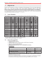
IGS
Technology for life safety and security
Ihr Partner in allen
Sicherheitsfragen
Internet: www.igs-hagen.de
Email: [email protected]
IGS Industrielle Gefahrenmeldesysteme GmbH
Hördenstraße 2
58135 Hagen
Tel.: +49 (0)2331 9787-0
Fax: +49 (0)2331 9787-87
Montage- und Bedienungsanleitung
Leserserie Insertic
Art.-Nr. 027666 - 027677.10
Berührungsloser Leser zur Integration
in Standard-Schalterdosen
P30729-45-002-08
2012-05-22
D
GB
Änderungen
vorbehalten
Montage- und Bedienungsanleitung Insertic Leser
2
Inhalt
1. Allgemeines . . . . . . . . . . . . . . . . . . . . . . . . . . . . . . . . . . . . . . . . . . . . . . . . . . . . . . . . . . . . . 3
1.1 Leser-Varianten . . . . . . . . . . . . . . . . . . . . . . . . . . . . . . . . . . . . . . . . . . . . . . . . . . . . . . . 3
1.2 Anwendungsgebiete . . . . . . . . . . . . . . . . . . . . . . . . . . . . . . . . . . . . . . . . . . . . . . . . . . . . 3
1.3 Besondere Merkmale . . . . . . . . . . . . . . . . . . . . . . . . . . . . . . . . . . . . . . . . . . . . . . . . . . . 4
1.4 Richtige Anwendung von Datenträgern . . . . . . . . . . . . . . . . . . . . . . . . . . . . . . . . . . . . . 4
1.5 Aufbau . . . . . . . . . . . . . . . . . . . . . . . . . . . . . . . . . . . . . . . . . . . . . . . . . . . . . . . . . . . . . . 4
2. Konfigurationsmöglichkeiten. . . . . . . . . . . . . . . . . . . . . . . . . . . . . . . . . . . . . . . . . . . . . . . 5
3. Montage . . . . . . . . . . . . . . . . . . . . . . . . . . . . . . . . . . . . . . . . . . . . . . . . . . . . . . . . . . . . . . . . 6
4. Klemmenbelegung . . . . . . . . . . . . . . . . . . . . . . . . . . . . . . . . . . . . . . . . . . . . . . . . . . . . . . . 8
5. Programmierung . . . . . . . . . . . . . . . . . . . . . . . . . . . . . . . . . . . . . . . . . . . . . . . . . . . . . . . . . 8
5.1 Voreinstellung der DIP-Schalter . . . . . . . . . . . . . . . . . . . . . . . . . . . . . . . . . . . . . . . . . . . 8
5.2 DIP-Schalter bei Lesern mit RS-485 Schnittstelle . . . . . . . . . . . . . . . . . . . . . . . . . . . . . 9
5.3 DIP-Schalter bei Lesern mit Clock/Data Schnittstelle. . . . . . . . . . . . . . . . . . . . . . . . . . . 9
6 LEDs und Summer bei ZK-Anwendung . . . . . . . . . . . . . . . . . . . . . . . . . . . . . . . . . . . . . 10
7. Einsatz der Leser an Einbruchmeldeanlagen . . . . . . . . . . . . . . . . . . . . . . . . . . . . . . . . . 11
7.1 Funktionen . . . . . . . . . . . . . . . . . . . . . . . . . . . . . . . . . . . . . . . . . . . . . . . . . . . . . . . . . . 11
7.2 Installation. . . . . . . . . . . . . . . . . . . . . . . . . . . . . . . . . . . . . . . . . . . . . . . . . . . . . . . . . . . 11
7.3 Programmierung . . . . . . . . . . . . . . . . . . . . . . . . . . . . . . . . . . . . . . . . . . . . . . . . . . . . . . 11
7.3.1 Leser anlegen . . . . . . . . . . . . . . . . . . . . . . . . . . . . . . . . . . . . . . . . . . . . . . . . . . . 11
7.3.2 Datenträger berechtigen . . . . . . . . . . . . . . . . . . . . . . . . . . . . . . . . . . . . . . . . . . . 11
7.4 Bedienungsanleitung 1
(Leser an IK3 AWE-BUS-2 / ZK-TM bis V10.xx und IK3 AWE konv.) . . . . . . . . . . . . . 12
7.4.1 Bedien- und Anzeigeelemente . . . . . . . . . . . . . . . . . . . . . . . . . . . . . . . . . . . . . . 12
7.4.2 Akustisches Quittiersignal. . . . . . . . . . . . . . . . . . . . . . . . . . . . . . . . . . . . . . . . . . 12
7.4.3 Scharf-/unscharfschalten . . . . . . . . . . . . . . . . . . . . . . . . . . . . . . . . . . . . . . . . . . 12
7.4.4 ZK-Funktion . . . . . . . . . . . . . . . . . . . . . . . . . . . . . . . . . . . . . . . . . . . . . . . . . . . . 14
7.4.5 ZK-Funktion nach dem Unscharfschalten. . . . . . . . . . . . . . . . . . . . . . . . . . . . . . 14
7.4.6 Lernmodus für Datenträger. . . . . . . . . . . . . . . . . . . . . . . . . . . . . . . . . . . . . . . . . 14
7.5 Bedienungsanleitung 2
(Leser an IK3 AWE-BUS-2 / ZK-TM ab V11.xx) . . . . . . . . . . . . . . . . . . . . . . . . . . . . . . 16
7.5.1 Bedien- und Anzeigeelemente . . . . . . . . . . . . . . . . . . . . . . . . . . . . . . . . . . . . . . 16
7.5.2 Akustische Quittiersignale. . . . . . . . . . . . . . . . . . . . . . . . . . . . . . . . . . . . . . . . . . 16
7.5.3 Scharf-/unscharfschalten . . . . . . . . . . . . . . . . . . . . . . . . . . . . . . . . . . . . . . . . . . 16
7.5.4 ZK-Funktion . . . . . . . . . . . . . . . . . . . . . . . . . . . . . . . . . . . . . . . . . . . . . . . . . . . . 18
7.5.5 ZK-Funktion nach dem Unscharfschalten. . . . . . . . . . . . . . . . . . . . . . . . . . . . . . 18
7.5.6 Lernmodus für Datenträger. . . . . . . . . . . . . . . . . . . . . . . . . . . . . . . . . . . . . . . . . 18
8. Technische Daten . . . . . . . . . . . . . . . . . . . . . . . . . . . . . . . . . . . . . . . . . . . . . . . . . . . . . . . 20
9. Pflegehinweise . . . . . . . . . . . . . . . . . . . . . . . . . . . . . . . . . . . . . . . . . . . . . . . . . . . . . . . . . 20
Montage- und Bedienungsanleitung Insertic Leser
1.
3
Allgemeines
Dieser Leser ist geeignet zum Einbau in Standard-uP-Schalterdosen. Durch seine flache Bauweise
ragt er nur 11 mm aus der Wand. Durch seine dezente Farbgebung passt er sich seiner
Einbauumgebung sowohl im industriellen als auch im privaten Umfeld harmonisch und unauffällig an.
Er kann zur allgemeinen Identifikation, für Zutrittskontrollanwendungen allgemein und als ZK-Option
der Zeitwirtschaft (mit ACS-2 plus Controllern) und bedingt auch für die Einbruchmeldetechnik
verwendet werden (Details siehe Kapitel 1.1, 1.2 und 7).
1.1
Leser-Varianten
Die verfügbaren Anschlusstypen und Leseverfahren entnehmen Sie bitte dieser Tabelle.
Artikelnummer proX1/2* mifare
LEGIC
Clock/Data** RS-485
prime advant
Tastatur
027666
027667
027668
027669
027670
027671
027672
027673
027674
027674.10
027675
027675.10
027676
027676.10
027677
027677.10
* bei EMZ: proX1=IK2, proX2=IK3 (ohne Wechselcode)
** nicht für EMZ-Anwendungen, ACT und ACU
1.2
Anwendungsgebiete
•
•
•
•
Zutrittskontrolle allgemein
Zeitwirtschaft (Option Zutrittskontrolle und ACS-2 plus Controller)
Allgemeine Benutzeridentifikation
Einbruchmeldetechnik (nur Leser mit RS-485-Schnittstelle)
Einsetzbar an:
IK3-AWE BUS-2 (023312 / 023312.10)
IK3-AWE konv. (023310)
ZK-Türmodul BUS-2 (023350 / 023350.10)
027668 - 677
(ohne Index .10)
ab V06.xx
ab V03.xx
ab V10.xx
027676.10
027677.10
ab V11.xx
i. V.
ab V11.xx
Insgesamt können bis zu 4 Leser an der IK3 AWE bzw. 2 Leser am ZK-Türmodul am
RS-485 Bus eingesetzt werden.
Es ist auch ein gemischter Betrieb verschiedener Lesertypen am RS-485 Bus möglich.
Einzelheiten siehe Montage-Anschluss-Anleitung IK3 AWE bzw. ZK-Türmodul.
Montage- und Bedienungsanleitung Insertic Leser
4
1.3
Besondere Merkmale
• Extrem flache Bauweise
- passt auf jede Gerätedose in Unterputz oder Hohlwandausführung nach DIN mit
Geräteschraubenabstand 60 mm
• Geeignet für Außen- und Inneneinsatz
• Anschlussart:
- Schraubklemmen (Liftsystem)
• Modularer Aufbau (generell zwei Module)
- Frontmodul mit integriertem Lesesystem
- drei LED-Leuchtfelder
- Sabotageüberwachung
- Rückmodul mit integrierter Schnittstelle
- DIP-Schalter
- Piezo Summer
- Schaltregler (8 bis 30 V DC)
- Anschlussklemmen
• proX-Leser mit Clock/Data-Schnittstelle umschaltbar auf Hitag 1 oder 2
• Lesetechnologie proX1 (IK2), proX2 (IK3 ohne Wechselcode)
1.4
Richtige Anwendung von Datenträgern
Um eine mögliche Beeinflussung mehrerer Datenträger beim Lesevorgang zu verhindern,
ist darauf zu achten, dass der gewünschte Datenträger separat ins Lesefeld gehalten
wird.
Bei Verwendung verschiedener Transponder im selben Frequenzbereich (125 kHz und
13,56 MHz) kann es bei unzureichendem Abstand der Transponder voneinander zu
Lesefehlern kommen. Es besteht kein Sicherheitsrisiko, nur die Lesung wird verhindert,
wenn sich mehrere Transponder im Lesebereich befinden
1.5
Aufbau
Frontmodul
Rückmodul
Montage- und Bedienungsanleitung Insertic Leser
2.
5
Konfigurationsmöglichkeiten
Clock/Data
Spannungsversorgung
HostSystem
zwei Eingänge für LED
Steuerung
Clock/Data
max. 10 Meter
RS-485-Bus (2-Draht)
Spannungsversorgung
HostSystem
1
RS-485-Bus
16
Montage- und Bedienungsanleitung Insertic Leser
6
3.
Montage
Zwischen berührungslosen Lesern muss ein Mindestabstand von 1 m in allen Richtungen
eingehalten werden.
Der Leser darf nicht direkt auf Metall montiert werden. Die Lesedistanz würde stark
vermindert werden.
Direkte Sonneneinstrahlung vermeiden.
Der Leser darf keinen kunststoffzersetzenden Lösungsmitteldämpfen ausgesetzt werden.
1. Anschlusskabel für Schnittstelle, Spannungszuführung entsprechend verlegen und zum
Anschließen vorbereiten.
Damit der Leser montiert werden kann, muss zunächst das Frontmodul vom
Rückmodul getrennt werden.
2. Sicherungsschraube entfernen
3. Einen beliebigen zylindrischen Gegenstand mit Æ max.
3 mm senkrecht von unten in die Aussparungen einführen und bis auf Anschlag nach oben drücken, so dass
sich das Frontmodul entriegelt.
5
4. Das entriegelte Frontmodul unten ca. 1 cm nach vorne
wegklappen.
O
I
5. Frontmodul leicht nach oben schieben bis es sich aus
den oberen Sicherungslaschen gelöst hat.
4
6. Frontmodul nach vorne aufklappen.
7. Lösen der Steckverbindung am Pfostenverbinder im
Rückmodul.
Achtung!
Frontmodulseitig nicht am roten Steckverbinder ziehen!
6
7
3
2
3
Montage- und Bedienungsanleitung Insertic Leser
8.
7
Rückmodul entsprechend der jeweiligen Anschlussbelegung (vgl. Kapitel 4) verdrahten.
Die Verdrahtung des Rückmoduls muss im spannungslosen Zustand erfolgen,
d. h. die Betriebsspannung darf erst nach vollständiger Montage des Lesers
eingeschaltet werden.
9.
Nach der Verdrahtung das Rückmodul
mittels den mitgelieferten Schrauben
auf eine DIN - Gerätedose mit Geräteschraubenabstand 60 mm schrauben.
10. DIP-Schalter 1 - 7 gemäß Kapitel 5
überprüfen, ggf. einstellen.
off on
12345678
11. DIP-Schalter 8:
DIP-Schalter 8 auf ON schalten, wenn
am Rückmodul bereits die Betriebsspannung angelegt ist.
Die Spannungszuführung für die Leserelektronik im Frontmodul wird deaktiviert.
Die Spannungszuführung für
die Leserelektronik im Frontmodul muss deaktiviert sein,
bevor das Frontmodul eingesteckt wird!
12. Anschlusskabel des Frontmoduls einstecken.
DIP-Schalter 8 wieder auf OFF stellen.
Die Spannungszuführung für die Leserelektronik im Frontmodul wird wieder
aktiviert.
13. Frontmodul auf dem Rückmodul fixieren und oben in die beiden Sicherungslaschen einhängen.
11
13
12
I
14
O
14. Frontmodul unten in Richtung Rückmodul drücken, bis die Verriegelungen
links und rechts komplett einrasten.
Bei einem erfolgreichen Einrastvorgang ist ein deutliches
"Klicken" zu hören bzw. auch
zu spüren.
15. Nach dem erfolgreichen Einrastvorgang
Sicherungsschraube einschrauben.
10
O
I
15
Montage- und Bedienungsanleitung Insertic Leser
8
4.
Klemmenbelegung
Rückmodul mit Schnittstelle (Rückansicht)
ST1
ST3
Anschlussklemme ST3
5-polige Schraubklemme
Nicht belegen!
1
2
3
4
5
6
7
5
4
3
2
1
Anschlussklemme ST1
7-polige Schraubklemme, Spannungsversorgung / Schnittstelle / LEDs
Klemmenspezifikation: Liftsystem / Anschlussdurchmesser 0,3 - 1,5 mm / Abisolierlänge 6 mm
Pin Nr.
1
2
3
4
5
6
7
5.
5.1
RS-485
intern belegt
intern belegt
Daten D*
Daten D
intern belegt
GND
+ U_b (8 bis 30 V DC)
Clock/Data
LED grün
LED rot
Clock
Open Kollektor
Data
"Aktiv Low"
intern belegt
GND
+ U_b (8 bis 30 V DC)
max.
10 mA
Programmierung
Rückmodul mit Schnittstelle
(Vorderansicht)
Voreinstellung der DIP Schalter
Die DIP-Schalter sind werksseitig
voreingestellt.
Sie dürfen nicht verändert werden.
off on
1
2
3
4
5
6
7
8
Ausnahmen:
- Bei RS-485 Lesern:
Geräteadresse (S1 bis S5)
Busabschlusswiderstand (S7)
- Bei Clock/Data Lesern:
Kartenart (S1 und S2 bei proX Lesern)
Summerfunktion (S1 bis S3 bei LEGIC advant Lesern)
- Bei allen Lesern:
Spannungsabschaltung für Frontmodul (S8)
Montage- und Bedienungsanleitung Insertic Leser
5.2
DIP-Schalter bei Lesern mit RS-485 Schnittstelle
Art. Nr.
027668 / 027669
027672 / 027673
027676 / 027677
027676.10 / 027677.10
DIP-Schalter
5 4 3 2
0 0 0 0
0 0 0 1
0 0 0 1
0 0 1 0
0 0 1 0
0 0 1 1
0 0 1 1
0 1 0 0
0 1 0 0
1 1 1
0 0 0
7
8
5.3
Leser
proX
mifare
LEGIC prime
LEGIC advant
Adresse
1
1
0
1
0
1
0
1
0
1
1
2
3
4
5
6
7
8
9
1 1
0 0
31
32
DIP-Schalter
6
9
OFF
ON
OFF
ON
OFF
ON
off on
1
2
3
4
5
6
7
8
Wertigkeit
1
2
4
8
16
Funktion
interne Funktion
nicht erlaubt
kein Busabschlusswiderstand
120 Ohm Busabschlusswiderstand
Spannung Frontmodul aktiv
Spannung Frontmodul abgeschaltet
DIP-Schalter bei Lesern mit Clock/Data Schnittstelle
DIPSchalter
1
2
3
4
5
6
7
8
S1 S2
OFF OFF
ON OFF
OFF ON
ON ON
ON
ON
ON
Funktion
Art. Nr.
Art. Nr.
Art. Nr.
027674.10 / 027675.10
027666 / 027667 027670 / 671 (mifare)
(LEGIC advant)
(proX)
027674 / 675 (LEGIC)
Summer nach Buchung
OFF Kartenart
intern belegt
Summer wie grüne LED (Eingang 1) OFF (siehe unten)
intern belegt
Summer wie rote LED (Eingang 2)
intern belegt
OFF (interne Funktion)
intern belegt
OFF = Spannung für Frontmodul aktiv
ON = Spannung für Frontmodul abgeschaltet
proX-Kartenart
EM4x02/V4x50 (Werkseinstellung)
Hitag1/Hitag S
Hitag2
nicht erlaubt
Montage- und Bedienungsanleitung Insertic Leser
10
6.
LEDs und Summer bei ZK-Anwendung
Die LEDs und der Summer werden über Bus gesteuert.
Die Definition ihrer Bedeutung wird in der jeweils übergeordneten Software hinterlegt.
Am Leser selbst können diesbezüglich keine Einstellungen vorgenommen werden.
Bei Lesern mit Clock/Data-Schnittstelle
leuchtet die gelbe LED permanent und ist nicht
abschaltbar.
grün
gelb
rot
Bei Lesern mit RS-485-Schnittstelle kann die
gelbe LED über die Software dunkel gesteuert
werden.
Bedeutung der LEDs
Farbe
Grundzustand
gelb
gelb
an
aus
grün
rot
grün
rot
rot
an
an
Nach Lesung
einer Karte
oder Tastatureingabe
an
an
blinkend
Bedeutung
Betrieb / lesebereit
Gerät ist spannungslos
PIN-Code- oder Türcodeeingabe ist aktiv
(nur bei Lesern mit RS-485 Schnittstelle möglich)
Dauerfrei
Dauergesperrt
Türfreigabe
Ausweis nicht berechtigt
Lesefehler
Es gelten zusätzlich die LED-Funktionen der Macrosteuerung von IQ MultiAccess (siehe
separate Anleitung "Weiterführende Funktionen zu IQ MultiAccess", P32205-46-000-xx).
Montage- und Bedienungsanleitung Insertic Leser
7.
7.1
11
Einsatz der Leser an Einbruchmeldeanlagen
Funktionen
Scharf-/unscharfschalten und/oder ZK-Funktion.
- Nur mit Datenträger (Togglebetrieb bei Leser ohne Tastatur)
- Mit PIN und Datenträger
- Mit PIN oder Datenträger
- Überfallcode-Eingabe auch bei unscharf möglich.
7.2
Installation
(Klemmenbelegung siehe Kap. 4, DIP-Schalter siehe Kap. 5)
-
RS-485 Adresse mit den DIP-Schaltern 1 - 5 einstellen.
RS-485 Abschlusswiderstand mit dem DIP-Schalter 7 ein- oder abschalten (abhängig vom
Bussystem, siehe Montage-Anschluss-Anleitung AWE / ZK-Türmodul).
- An IK3 AWE / ZK-Türmodul anschließen
Wichtiger Hinweis: Die Spannungsversorgung muss über eine separat abgesicherte Quelle
erfolgen (bedingt durch die hohe Stromaufnahme des Lesers), z. B. U_ext. von der Zentrale oder
separates Netzteil.
7.3
Programmierung
7.3.1 Leser anlegen
Leser als IK3-Bedienteil mit Seriennummer 00000-00000 anlegen.
Mehrere Leser mit Seriennummer 00000-00000 können ab EMZ-Firmware V05.09 und WINFEM
Advanced V01.xx angelegt werden.
Bei Lesern ohne Tastatur ist zu beachten, dass kein Tastaturcode eingegeben werden darf und bei
Berechtigung "nur Datenträger" einzustellen ist.
7.3.2 Datenträger berechtigen
Da in der EMT andere Codes als bei ZKA verwendet werden, kann der auf dem Datenträger
angegebene Code nicht benutzt werden.
Deshalb müssen die Datenträger gelernt werden.
- IK3 AWE BUS-2 / ZK-Türmodul:
Die Datenträger werden gelernt mit Hilfe der Einmannrevision
- F:402 "Schalteinrichtungen prüfen"
und anschließender Verwendung eines Lernschlüssels
- F:308 "Lernmonitor".
In diesen Funktionen werden bei Bedarf auch Lernschlüssel angelegt. Der für die EMT gültige
Code wird bei einem gelesenen Datenträger angezeigt und kann dann als Lernschlüssel-Code
eingetragen werden.
- IK3 AWE konventionell:
Siehe Anleitung WINFEM Advanced (P03174-20-00x.xx).
Datenträger lernen siehe Kap. 7.4.6 bzw. 7.5.6 (abhängig vom Firmwarestand IK3 AWE/ZKTürmodul).
Montage- und Bedienungsanleitung Insertic Leser
12
7.4
Bedienungsanleitung 1
Leser an IK3 AWE-BUS-2 / ZK-TM bis V10.xx und IK3 AWE konv.
Ab IK3 AWE BUS-2 / ZK-Türmodul ab V11.xx gilt Kap. 7.5 "Bedienungsanleitung 2".
7.4.1 Bedien- und Anzeigeelemente
LEDs
grün gelb rot
Bedeutung der LEDs:
grün: bereit
gelb: unscharf
rot: Alarm
Im Ruhezustand sind alle Anzeigen
dunkel. Bei der Durchführung einer
Funktion wird die Anzeige für ca. 5
Sekunden entsprechend der Funktion
angesteuert.
Details siehe folgende Kapitel.
Der Zustand der LED-Anzeige wird wie folgt dargestellt:
ein
unscharfschalten
scharfschalten
blinkt
aus
7.4.2 Akustisches Quittiersignal
- Summersignal:
Es erfolgt eine akustische Quittierung durch einen langen Signalton.
1 Sek.
Es wird nicht unterschieden zwischen Lesequittierung, positiver und negativer
Quittierung.
7.4.3 Scharf-/unscharfschalten einer EMZ (nur über IK3 AWE)
!
Leser mit Tastatur
- Datenträger ins Lesefeld halten und wieder entfernen.
Grüne LED leuchtet.
Gelbe LED leuchtet im Unscharfzustand, im Scharfzustand ist sie dunkel.
- Taste "scharfschalten" bzw. "unscharfschalten" drücken.
- Quittierung erfolgt (siehe folgende Tabellen).
!
Leser ohne Tastatur
- Datenträger ins Lesefeld halten und wieder entfernen.
Grüne LED leuchtet.
Gelbe LED leuchtet im Unscharfzustand, im Scharfzustand ist sie dunkel.
- Nach 1 bis 4 Sekunden Datenträger erneut ins Lesefeld halten.
- Quittierung erfolgt (siehe folgende Tabellen).
Montage- und Bedienungsanleitung Insertic Leser
13
Quittierung beim Scharfschalten
Optisch
Bereit
(grün)
Unscharf
(gelb)
Bei Berechtigung und
Zwangsläufigkeit erfüllt
Bei Berechtigung, aber
keine Zwangsläufigkeit
5 Sek.
5 Sek.
unscharf
scharf
Alarm
(rot)
Akustisch
(Signalton)
Aktion
Keine Berechtigung
5 Sek.
leuchtet bei Alarm
1 Sek.
1 Sek.
Quittierung
Quittierung
1 Sek.
Quittierung
Anlage wird nicht
scharfgeschaltet
Anlage wird nicht
scharfgeschaltet
Bei Berechtigung und
Zwangsläufigkeit erfüllt
Bei Berechtigung, aber
keine Zwangsläufigkeit
Keine Berechtigung
5 Sek.
5 Sek.
Anlage wird
scharfgeschaltet
Quittierung beim Unscharfschalten
Optisch
Bereit
(grün)
Unscharf
(gelb)
scharf
unscharf
5 Sek.
Alarm
(rot)
leuchtet bei Alarm
leuchtet bei Alarm
Akustisch
(Signalton)
1 Sek.
1 Sek.
Aktion
1 Sek.
Quittierung
Quittierung
Quittierung
Anlage wird
unscharfgeschaltet
Anlage wird nicht
unscharfgeschaltet
Anlage wird nicht
unscharfgeschaltet
Montage- und Bedienungsanleitung Insertic Leser
14
7.4.4 ZK-Funktion (Tür öffnen)
- Datenträger ins Lesefeld halten.
- Quittierung erfolgt.
Quittierung bei ZK-Funktion
Optisch
Bei Berechtigung
Keine Berechtigung oder
ZK-Funktion nicht aktiviert
Bereit (grün)
5 Sek.
Unscharf (gelb)
Akustisch
(Signalton)
Aktion
1 Sek.
Quittierung
zeitgesteuerte
Türfreigabe
1 Sek.
Quittierung
keine Türfreigabe
7.4.5 ZK-Funktion nach dem Unscharfschalten
In Abhängigkeit der Anlagenprogrammierung entweder
- Zuerst unscharfschalten (siehe 7.4.3).
- Um die Tür zu öffnen, muss der Datenträger ein weiteres Mal ins Lesefeld gehalten
werden.
oder
- nach Unscharfschalten wird automatisch die ZK-Funktion aktiviert.
7.4.6 Lernmodus für Datenträger
Im Lernmodus können Sie auf einfache Weise neue Datenträger berechtigen oder bereits vorhandene löschen. Neu "gelernte" Datenträger sind automatisch generalberechtigt, ab Version V9
(MB24/48/100) und Version V3 (Mb256 plus) müssen anschließend über die Programmierung
PINs / Berechtigungen / Zeitzonen zuweisen werden.
Zum Starten des Lernmodus benötigen Sie einen "Lernschlüssel". Dabei handelt es sich um
einen Datenträger, der ausschließlich für diesen Zweck im System angelegt ist. Der Lernschlüssel
besitzt jedoch keine Berechtigungen.
Solange der Lernmodus aktiviert ist, können Sie beliebig viele Datenträger nacheinander lernen
oder löschen.
Die Anzeigen "Bereit" (grün) und "Unscharf (gelb) dienen im Lernmodus als
optische Quittierungssignale.
Akustische Quittiersignale:
- Summerton einfach:
Ausgeführte Aktion erfolgreich, Lernmodus aktiviert oder Datenträger geSummerton einfach
lernt.
- Summerton zweifach: Datenträger gelöscht.
- Summerton dreifach: Vorgang nicht zulässig.
Ein unzulässiger Vorgang liegt dann vor, Summerton zweifach
wenn ein programmierter Datenträger
gelernt oder ein nicht
programmierter Datenträger gelöscht
werden soll.
Summerton dreifach
Der Lernmodus ist nur im unscharfen Zustand möglich.
Montage- und Bedienungsanleitung Insertic Leser
!
Leser mit Tastatur
Lernmodus starten
L
Lernschlüssel ins Lesefeld halten bis zum
Summersignal
LEDs grün und gelb leuchten
Taste " I " betätigen,
kurzes Summersignal
LEDs grün und gelb blinken,
der Lernmodus ist eingeschaltet
Datenträger lernen
ID
Neuen Datenträger ins Lesefeld halten bis zum
Summersignal
LED grün leuchtet, LED gelb blinkt
Taste " I " betätigen
kurzes Summersignal
LEDs grün und gelb blinken
Datenträger löschen
Lernmodus beenden
ID
L
Alten Datenträger ins Lesefeld halten bis zum
Summersignal
LED grün leuchtet, LED gelb blinkt
Taste "O" betätigen
2 kurze Summersignale
LEDs grün und gelb blinken
Lernschlüssel ins Lesefeld halten bis zum Summersignal, dann Taste "O" betätigen
oder
automatisch ca. 60 Sek. nach dem letzten Bedienvorgang
LEDs grün und gelb gehen aus
!
15
Leser ohne Tastatur
Lernmodus starten
L
Lernschlüssel ins Lesefeld halten bis zum
Summersignal
LEDs grün und gelb leuchten
LEDs grün und gelb blinken,
der Lernmodus ist eingeschaltet
Datenträger lernen
ID
Neuen Datenträger ins Lesefeld halten
bis zum Summersignal
LED grün leuchtet, LED gelb blinkt
Summerquittierung
LEDs grün und gelb blinken
Lernmodus beenden
L
Lernschlüssel ins Lesefeld halten bis zum Summersignal
oder
automatisch ca. 60 Sek. nach dem letzten Bedienvorgang
LEDs grün und gelb gehen aus
Montage- und Bedienungsanleitung Insertic Leser
16
7.5
Bedienungsanleitung 2
Leser an IK3 AWE-BUS-2 / ZK-TM ab V11.xx
7.5.1 Bedien- und Anzeigeelemente
LEDs
grün gelb rot
Bedeutung der LEDs:
grün: bereit
gelb: unscharf
rot: Alarm
Im Ruhezustand sind alle Anzeigen
dunkel. Bei der Durchführung einer
Funktion wird die Anzeige für ca. 5
Sekunden entsprechend der Funktion
angesteuert.
Details siehe folgende Kapitel.
Der Zustand der LED-Anzeige wird wie folgt dargestellt:
ein
unscharfschalten
scharfschalten
blinkt
aus
7.5.2 Akustische Quittiersignale
- Summersignale:
Lesequittierung nach jeder Tastenbetätigung
oder Datenträgerquittierung.
Positive Quittierung
für eine erfolgreich durchgeführte Aktion.
Negative Quittierung (4x kurz in 1 Sek.)
Es liegt keine Berechtigung vor oder
die Aktion kann nicht durchgeführt werden.
125 ms
2 Sek.
1 Sek.
7.5.3 Scharf-/unscharfschalten einer EMZ (nur über IK3 AWE)
!
Leser mit Tastatur
- Taste "scharfschalten" bzw. "unscharfschalten" drücken.
Grüne LED leuchtet.
Gelbe LED leuchtet im Unscharfzustand, im Scharfzustand ist sie dunkel.
- Datenträger ins Lesefeld halten und wieder entfernen.
- Quittierung erfolgt (siehe folgende Tabellen).
!
Leser ohne Tastatur
- Datenträger ins Lesefeld halten und wieder entfernen.
Grüne LED leuchtet.
Gelbe LED leuchtet im Unscharfzustand, im Scharfzustand ist sie dunkel.
- Nach 1 bis 4 Sekunden Datenträger erneut ins Lesefeld halten.
- Quittierung erfolgt (siehe folgende Tabellen).
Montage- und Bedienungsanleitung Insertic Leser
17
Quittierung beim Scharfschalten
Optisch
Bei Berechtigung und
Zwangsläufigkeit erfüllt
Bei Berechtigung, aber
keine Zwangsläufigkeit
5 Sek.
5 Sek.
Bereit
(grün)
Unscharf
(gelb)
unscharf
scharf
Alarm
(rot)
Akustisch
(Signalton)
Aktion
Keine Berechtigung
5 Sek.
leuchtet bei Alarm
2 Sek.
Positiv-Quittierung
Negativ-Quittierung
Negativ-Quittierung
Anlage wird
scharfgeschaltet
Anlage wird nicht
scharfgeschaltet
Anlage wird nicht
scharfgeschaltet
Bei Berechtigung und
Zwangsläufigkeit erfüllt
Bei Berechtigung, aber
keine Zwangsläufigkeit
Keine Berechtigung
5 Sek.
5 Sek.
Quittierung beim Unscharfschalten
Optisch
Bereit
(grün)
Unscharf
(gelb)
scharf
unscharf
Alarm
(rot)
leuchtet bei Alarm
Akustisch
(Signalton)
2 Sek.
Aktion
5 Sek.
leuchtet bei Alarm
Positiv-Quittierung
Negativ-Quittierung
Negativ-Quittierung
Anlage wird
unscharfgeschaltet
Anlage wird nicht
unscharfgeschaltet
Anlage wird nicht
unscharfgeschaltet
Montage- und Bedienungsanleitung Insertic Leser
18
7.5.4 ZK-Funktion (Tür öffnen)
- Datenträger ins Lesefeld halten.
- Quittierung erfolgt.
Quittierung bei ZK-Funktion
Optisch
Bei Berechtigung
Keine Berechtigung oder
ZK-Funktion nicht aktiviert
Bereit (grün)
5 Sek.
Unscharf (gelb)
Akustisch
(Signalton)
Aktion
2 Sek.
Positiv-Quittierung
zeitgesteuerte
Türfreigabe
Negativ-Quittierung
keine Türfreigabe
7.5.5 ZK-Funktion nach dem Unscharfschalten
In Abhängigkeit der Anlagenprogrammierung entweder
- Zuerst unscharfschalten (siehe 7.5.3).
- Um die Tür zu öffnen, muss der Datenträger ein weiteres Mal ins Lesefeld gehalten
werden.
oder
- nach Unscharfschalten wird automatisch die ZK-Funktion aktiviert.
7.5.6 Lernmodus für Datenträger
Im Lernmodus können Sie auf einfache Weise neue Datenträger berechtigen oder bereits vorhandene löschen. Neu "gelernte" Datenträger sind automatisch generalberechtigt, ab Version V9
(MB24/48/100) und Version V3 (Mb256 plus) müssen anschließend über die Programmierung
PINs / Berechtigungen / Zeitzonen zuweisen werden.
Zum Starten des Lernmodus benötigen Sie einen "Lernschlüssel". Dabei handelt es sich um
einen Datenträger, der ausschließlich für diesen Zweck im System angelegt ist. Der Lernschlüssel
besitzt jedoch keine Berechtigungen.
Solange der Lernmodus aktiviert ist, können Sie beliebig viele Datenträger nacheinander lernen
oder löschen.
Die Anzeigen "Bereit" (grün) und "Unscharf (gelb) dienen im Lernmodus als
optische Quittierungssignale. Rot leuchtet bei Alarm.
Akustische Quittiersignale:
Positive Quittierung:
Negative Quittierung:
- Lernmodus aktiviert
- Datenträger gelernt
- Datenträger gelöscht
Vorgang nicht zulässig.
Ein unzulässiger Vorgang liegt dann vor,
wenn ein programmierter Datenträger
gelernt oder ein nicht programmierter
Datenträger gelöscht werden soll.
Der Lernmodus ist nur im unscharfen Zustand möglich.
2 Sek.
1 Sek.
Montage- und Bedienungsanleitung Insertic Leser
!
Leser mit Tastatur
19
Rot leuchtet bei Alarm
Lernmodus starten
L
Lernschlüssel ins Lesefeld halten bis zum
Summersignal
LEDs grün und gelb leuchten
Taste " I " betätigen,
kurzes Summersignal
LEDs grün und gelb blinken,
der Lernmodus ist eingeschaltet
Datenträger lernen
ID
Neuen Datenträger ins Lesefeld halten bis zum
Summersignal
LED grün leuchtet, LED gelb blinkt
Taste " I " betätigen
Summerquittierung
LEDs grün und gelb blinken
Datenträger löschen
Lernmodus beenden
ID
L
Alten Datenträger ins Lesefeld halten bis zum
Summersignal
LED grün leuchtet, LED gelb blinkt
Taste "O" betätigen
Summerquittierung
LEDs grün und gelb blinken
Lernschlüssel ins Lesefeld halten bis zum Summersignal, dann Taste "O" betätigen
oder
nur Taste "O" betätigen
oder
automatisch ca. 60 Sek. nach dem letzten Bedienvorgang
Alle LEDs gehen aus
!
Leser ohne Tastatur
Lernmodus starten
Rot leuchtet bei Alarm
L
Lernschlüssel ins Lesefeld halten bis zum
Summersignal
LEDs grün und gelb leuchten
LEDs grün und gelb blinken,
der Lernmodus ist eingeschaltet
Datenträger lernen
ID
Neuen Datenträger ins Lesefeld halten
bis zum Summersignal
LED grün leuchtet, LED gelb blinkt
Summerquittierung
LEDs grün und gelb blinken
Lernmodus beenden
L
Lernschlüssel ins Lesefeld halten bis zum Summersignal
oder
automatisch ca. 60 Sek. nach dem letzten Bedienvorgang
Alle LEDs gehen aus
Montage- und Bedienungsanleitung Insertic Leser
20
8.
Technische Daten
Betriebsnennspannung
Betriebsspannungsbereich
Leistungsaufnahme max.
Betriebstemperaturbereich
Lagertemperaturbereich
Schnittstellen (geräteabhängig)
Signalelemente:
Firmware / Softwareprotokolle
(geräteabhängig)
Gehäuse Frontmodul und Rückmodul
Abmessungen (BxHxT)
Gehäuse, Einbauteil (ØxT)
Schutzart:
12 V DC
8 bis 30 V DC
2,5 Watt
-25 °C bis +60 °C
-30 °C bis +70 °C
RS-485 (D, D*), nicht galvanisch getrennt,
Adresseinstellung über DIP Schalter,
zuschaltbarer Bus-Abschlusswiderstand
(DIP Schalter) oder Clock/Data
3 LEDs grün, gelb, rot
1 Piezo Summer
Clock/Data oder RS-485 (Modulbus)
Kunststoff
81 x 81 x 11 mm
56 x 24 mm
Frontseitig (in montiertem Zustand) IP 54
Die Abdichtung gegen die Montagewand
bestimmt die maximal erreichbare Schutzart
IP 54.
Unterstützte Datenträger
- LEGIC prime MIM 256 / MIM 1024
Geräte mit Artikelnummer .10:
zusätzlich LEGIC advant
Lesedistanz
typ. 4 cm mit Ausweiskarten im EC-Format
typ. 2 cm mit Schlüsselanhängern
- proX (125 kHz)
HITAG (Hitag 1, Hitag 2, Hitag S)
EM 4102
Lesedistanz
typ. 4 cm mit Ausweiskarten im EC-Format
typ. 2 cm mit Schlüsselanhängern
- mifare Classic (1 kByte)
Lesedistanz
typ. 4 cm mit Ausweiskarten im EC-Format
typ. 2 cm mit Schlüsselanhängern
1)
1)
1)
1)
Die angegebene Lesedistanz kann nur bei Verwendung von ID-Datenträgern aus unserem
Haus garantiert werden.
EG-Konformität
Das Gerät entspricht bei bestimmungsgemäßer Anwendung den grundlegenden
Anforderungen gemäß Artikel 3 der R&TTE-Richtlinie 1999/5/EG.
Die EG-Konformitätserklärung steht auf unserer Homepage zum Download bereit.
9.
Pflegehinweise
Gerät bitte nicht mit scharfkantigen Gegenständen bedienen! Vorsicht mit Fingernägeln, Ringen
etc. Zur Bedienung nur leicht berühren.
Zum Reinigen keine ätzenden oder Kunststoff zersetzende Flüssigkeiten wie Benzin, Terpentin,
Nitro etc. verwenden.
Scharfe Reinigungsmittel können die Oberflächen beschädigen oder verfärben.
Keine Reinigungsmittel verwenden, die auf mechanischer Basis wirken, z. B. Scheuermilch,
Scheuerschwamm etc.
Reinigung mit weichem, feuchtem Tuch. Nur klares Wasser verwenden.
Montage- und Bedienungsanleitung Insertic Leser
Notizen
21
Honeywell Security Group
Novar GmbH
Johannes-Mauthe-Straße 14
D-72458 Albstadt
www.honeywell.com/security/de
P30729-45-002-08
2012-05-22
© 2012 Novar GmbH
Mounting and Operating Instructions
Reader series Insertic
Item no. 027666 - 027677.10
Contactless reader for integration
in standard mounting boxes
P30729-45-002-08
2012-05-22
D
GB
Subject to change
without notice
24
Mounting and Operating Instructions Insertic readers
Contents
1. General . . . . . . . . . . . . . . . . . . . . . . . . . . . . . . . . . . . . . . . . . . . . . . . . . . . . . . . . . . . . . . . . 25
1.1 Reader versions . . . . . . . . . . . . . . . . . . . . . . . . . . . . . . . . . . . . . . . . . . . . . . . . . . . . . . 25
1.2 Applications. . . . . . . . . . . . . . . . . . . . . . . . . . . . . . . . . . . . . . . . . . . . . . . . . . . . . . . . . . 25
1.3 Specials. . . . . . . . . . . . . . . . . . . . . . . . . . . . . . . . . . . . . . . . . . . . . . . . . . . . . . . . . . . . . 26
1.4 Correct application of data carriers . . . . . . . . . . . . . . . . . . . . . . . . . . . . . . . . . . . . . . . . 26
1.5 Construction . . . . . . . . . . . . . . . . . . . . . . . . . . . . . . . . . . . . . . . . . . . . . . . . . . . . . . . . . 26
2. Configuration possibilities . . . . . . . . . . . . . . . . . . . . . . . . . . . . . . . . . . . . . . . . . . . . . . . . 27
3. Mounting. . . . . . . . . . . . . . . . . . . . . . . . . . . . . . . . . . . . . . . . . . . . . . . . . . . . . . . . . . . . . . . 28
4. Terminal allocation . . . . . . . . . . . . . . . . . . . . . . . . . . . . . . . . . . . . . . . . . . . . . . . . . . . . . . 30
5. Programming . . . . . . . . . . . . . . . . . . . . . . . . . . . . . . . . . . . . . . . . . . . . . . . . . . . . . . . . . . . 30
5.1 DIP-switch factory setting . . . . . . . . . . . . . . . . . . . . . . . . . . . . . . . . . . . . . . . . . . . . . . . 30
5.2 DIP-switches RS-485 readers. . . . . . . . . . . . . . . . . . . . . . . . . . . . . . . . . . . . . . . . . . . . 31
5.3 DIP-switches Clock/Data readers . . . . . . . . . . . . . . . . . . . . . . . . . . . . . . . . . . . . . . . . . 31
6. LEDs and buzzer with AC applications . . . . . . . . . . . . . . . . . . . . . . . . . . . . . . . . . . . . . . 32
7. Application with intrusion control panels . . . . . . . . . . . . . . . . . . . . . . . . . . . . . . . . . . . . 33
7.1 Functions. . . . . . . . . . . . . . . . . . . . . . . . . . . . . . . . . . . . . . . . . . . . . . . . . . . . . . . . . . . . 33
7.2 Installation . . . . . . . . . . . . . . . . . . . . . . . . . . . . . . . . . . . . . . . . . . . . . . . . . . . . . . . . . . . 33
7.3 Programming. . . . . . . . . . . . . . . . . . . . . . . . . . . . . . . . . . . . . . . . . . . . . . . . . . . . . . . . . 33
7.4 Operating instruction 1
(Reader on IK3 EU BUS-2 / DCM up to V10.xx and IK3 EU conventional) . . . . . . . . . 34
7.4.1 Operating and indication elements . . . . . . . . . . . . . . . . . . . . . . . . . . . . . . . . . . . 34
7.4.2 Acoustic acknowledgement. . . . . . . . . . . . . . . . . . . . . . . . . . . . . . . . . . . . . . . . . 34
7.4.3 Arm/disarm an intrusion control panel. . . . . . . . . . . . . . . . . . . . . . . . . . . . . . . . . 34
7.4.4 Door opening (Access control function) . . . . . . . . . . . . . . . . . . . . . . . . . . . . . . . 36
7.4.5 AC function after disarming . . . . . . . . . . . . . . . . . . . . . . . . . . . . . . . . . . . . . . . . . 36
7.4.6 Learning mode for data carriers . . . . . . . . . . . . . . . . . . . . . . . . . . . . . . . . . . . . . 36
7.5 Operating instruction 2
(Reader on IK3 EU BUS-2 / DCM from V11.xx). . . . . . . . . . . . . . . . . . . . . . . . . . . . . . 38
7.5.1 Operating and indication elements . . . . . . . . . . . . . . . . . . . . . . . . . . . . . . . . . . . 38
7.5.2 Acoustic acknowledgement. . . . . . . . . . . . . . . . . . . . . . . . . . . . . . . . . . . . . . . . . 38
7.5.3 Arm/disarm an intrusion control panel. . . . . . . . . . . . . . . . . . . . . . . . . . . . . . . . . 38
7.5.4 Door opening (Access control function) . . . . . . . . . . . . . . . . . . . . . . . . . . . . . . . 40
7.5.5 AC function after disarming . . . . . . . . . . . . . . . . . . . . . . . . . . . . . . . . . . . . . . . . . 40
7.5.6 Learning mode for data carriers . . . . . . . . . . . . . . . . . . . . . . . . . . . . . . . . . . . . . 40
8. Technical data . . . . . . . . . . . . . . . . . . . . . . . . . . . . . . . . . . . . . . . . . . . . . . . . . . . . . . . . . . 42
9. Care and correct use . . . . . . . . . . . . . . . . . . . . . . . . . . . . . . . . . . . . . . . . . . . . . . . . . . . . . 42
25
Mounting and Operating Instructions Insertic readers
1.
General
This reader is suitable for installation into standard flush-mounted mounting boxes. Due do its flat
design it pokes out of the wall only 11 mm. Its unobtrusive coloring allows harmonious and
unconspicuous integration in industrial environment as well as in private.
It can be used for general indentification, for access control applications in general and with the AC
option of time management systems (in combination with ACS-2 plus controllers) and conditionally
for intrusion detection technique (details see chapter 1.1, 1.2 and 7).
1.1
Reader versions
For available connection types and reading procedures see table below.
Item no.
proX1/2* mifare
LEGIC
Clock/Data** RS-485
prime advant
Keypad
027666
027667
027668
027669
027670
027671
027672
027673
027674
027674.10
027675
027675.10
027676
027676.10
027677
027677.10
* with IACP: proX1=IK2, proX2=IK3 (without changing code)
** not for IACP (= Intruder Alarm Control Panel) applications, ACD and ACU
1.2
Applications
•
•
•
•
Access control (in general)
Time management (access control option in combination with ACS-2 plus controllers)
General user identification
Intrusion alarm systems (readers with RS-485 interface only)
The readers can be operated with:
IK3-EU BUS-2 (023312 / 023312.10)
IK3-EU conv. (023310)
Door Controller Module for MB (023350 / 023350.10)
027668- 677
(w/o Index .10)
from V06.xx
from V03.xx
from V10.xx
027676.10
027677.10
from V11.xx
in prep.
from V11.xx
A total of up to 4 readers (IK3 EU) or 2 readers (DCM) can be connected to a single RS485 bus. Mixed operation of different reader types on the RS-485 bus is also possible.
See IK3 EU or DCM Mounting and Connection Instructions for details.
26
1.3
Mounting and Operating Instructions Insertic readers
Specials
• Extremly flat construction
- fits into each box for flush mounting or mounting in hollow walls according to DIN with
with a screw distance of 60 mm
• Suitable for outdoor and indoor use
• Type of connection:
- Screw terminals (lift system)
• Seperated construction (two modules in general)
- Front module with integrated reader system
- three LED lightning fields
- Back module with integrated interface
- DIP-Switches
- Piezo Buzzer
- Switching regulator (8 to 30 V DC)
- Connection terminals
• proX reader with Clock/Data interface switchable to Hitag 1 or 2
• Reading technology proX1 (IK2) , proX2 (IK3 without changing code)
1.4
Correct application of data carriers
In order to prevent several data carriers affecting the read process, ensure that the desired
data carrier is held separately in the reading range.
When using several transponders of the same frequency range (125 kHz and 13,56 MHz),
reading errors can occur with insufficient distance between the transponders. There is no
safety risk, only the reading will be prevented if there are several transponders within the
reading area.
1.5
Construction
Back module
Front module
27
Mounting and Operating Instructions Insertic readers
2.
Configuration possibilities
Clock/Data
Power supply
HostSystem
Two inputs for LED
control
Clock/Data
max. 10 meters
RS-485-Bus (2-wire)
Power supply
HostSystem
1
RS-485-Bus
16
28
3.
Mounting and Operating Instructions Insertic readers
Mounting
Between contactless readers must be a minimum distance of 1 m in all directions.
Do not install the reader directly on metal as this would considerably reduce the reading
distance.
Avoid direct sun rays.
The reader should not be exposed to plastic decomposing solvent vapours.
1.
Prepare the connection cables for the interface and the power supply and prepare them for
connecting.
To install the reader, the front module must be separated from the back module at
first.
2.
Remove locking screw
3.
Insert any cylindrical object with max. ø3 mm
vertically from below into the gap and press it by stop
means upwards in order to runbolt the front module.
4.
Swing open the lower side of the unbolted front
module about 1 cm to the front.
5.
Push the front module carefully upwards until it
comes off the upper locking loops.
5
O
I
4
6.
Swing open the front module to the front.
7.
Remove the connector of the back module.
3
Caution!
Do not pull at the red connector of the front module!
6
7
2
3
29
Mounting and Operating Instructions Insertic readers
8. Do the wiring of the back module according to the required connection type (see chapter 4).
The wiring of the back module must be done in voltageless condition,
which means the operating voltage may be switched on after
finishing the complete installation only.
Screw the back module into a DIN
installation box with a screw distance
of 60 mm using the included screws
after wiring.
10. Set the DIP-Switches 1 to 7 according
to the individually required interface
and firmware function/protocol (see
chapter 5).
off on
12345678
11. DIP-Switch 8:
If the operating voltage is already
connected in open condition of the
back module, set DIP-switch 8 to
position ON.
The voltage for the reading electronics
of the front module is now deactivated.
10
11
The voltage for the reading
electronics of the front module
must be deactivated before
the front module will be
attached.
12. Plug the connector of the front module
into the socket of the back module.
Set DIP-Switch 8 to position OFF again
(power supply for reading electronics
of the front module will be reactivated).
13. Fix the front modue on the back
module and hang it up into both of the
locking loops at the upper side.
13
12
I
14
O
14. Press the lower part of the front module
to the direction of the back module until
the locking mechanisms to the left and
right side engage completely.
With a succsessful engagement a clear "click" can be
heared and felt.
O
I
15. Screw in again the locking screw after
succsessful engagement.
15
30
4.
Mounting and Operating Instructions Insertic readers
Terminal allocation
Back module with interface (back view)
ST1
ST3
Connection terminal ST3
5pole screw terminal
Do not use!
1
2
3
4
5
6
7
5
4
3
2
1
Connection terminal St1
7pole screw terminal, power supply / interface / LEDs
Terminal specification:
Lift system / connection diameter 0,3 - 1,5 mm / stripped length of
wire 6 mm
Pin no.
1
2
3
4
5
6
7
5.
5.1
RS-485
internally connected
internally connected
Data D*
Data D
internally connected
GND
+ U_b (8 to 30 V DC)
"Magastripe" Clock/Data
LED green
LED red
Clock
Open Collector
Data
"Active Low"
internally connected
GND
+ U_b (8 to 30 V DC)
max.
10 mA
Programming
DIP-switch factory setting
The factory settings of the DIP-switches
are preset according to the individual
reader type.
Do not change them!
Back module with interface
(front view)
off on
1
2
3
4
5
6
7
8
Exceptions:
- RS-485 readers :
Device address (S1 to S5)
Bus terminating resistor (S7)
- Clock/Data readers:
Card type (proX readers, S1 and S2)
Buzzer function (LEGIC advant readers, S1 to S3)
- All readers:
Power supply front module (S8)
TOP
31
Mounting and Operating Instructions Insertic readers
5.2
DIP-switches RS-485 readers
Item no.
027668 / 027669
027672 / 027673
027676 / 027677
027676.10 / 027677.10
DIP-switch
5 4 3 2
0 0 0 0
0 0 0 1
0 0 0 1
0 0 1 0
0 0 1 0
0 0 1 1
0 0 1 1
0 1 0 0
0 1 0 0
1 1 1
0 0 0
7
8
5.3
Address
1
2
3
4
5
6
7
8
9
off on
Valence
1
2
3
4
5
6
7
8
1
2
4
8
16
31
32
1 1
0 0
DIP-swith
6
1
1
0
1
0
1
0
1
0
1
Readers
proX
mifare
LEGIC prime
LEGIC advant
Function
OFF
ON
OFF
ON
OFF
ON
internal used
not allowed
no terminating resistor
120 Ohm terminating resistor
power supply front module active
power supply front module disabled
DIP-switches Clock/Data readers
DIPswitch
1
2
3
4
5
6
7
8
S1 S2
OFF OFF
ON OFF
OFF ON
ON ON
Function
Item no.
027674.10 / 027675.10
(LEGIC advant)
ON Buzzer booking message
ON Buzzersignal like green LED (input 1)
ON Buzzersignal like red LED (input 2)
internal used
OFF (internal used)
internal used
OFF = power supply front module active
ON = power supply front module disabled
proX Card type
EM4x02/V4x50 (factory setting)
Hitag1/Hitag S
Hitag2
not allowed
Item no.
Item no.
027666 / 027667 027670 / 671 (mifare)
(proX)
027674 / 675 (LEGIC)
OFF Card type
internal used
OFF (see below)
internal used
32
Mounting and Operating Instructions Insertic readers
6.
LEDs and buzzer with AC applications
The LEDs and the buzzer are controlled over a bus system. The definition for each is specified in the
main software and not at the reader.
At readers with Clock/Data interface the yellow LED
lights permanently and can not be switched off.
green yellow
red
At readers with RS-485 interface the yellow LED can
be switched dark via software.
LED meaning
Color
Basic
condition
yellow
yellow
on
off
green
red
green
red
red
on
on
After reading
a card or after
a keystroke
on
on
blinking
Meaning
Operation / ready to read
Device is idle
PIN-Code or door code entry is active
(only possible with readers with RS-485 interface)
Permanently released
Permanently blocked
Door release
ID card not authorized
Read error
Additionally, the LED functions of the macro control of IQ MultiAccess are valid (see
separate manual "Supplementary functions of IQ MultiAccess", P32205-46-0G0-xx).
Mounting and Operating Instructions Insertic readers
7.
7.1
33
Application with intrusion control panels
Functions
Arming/Disarming and/or AC function.
- Only with data carrier (reader without keypad is operated with toggle)
- With PIN and data carrier
- With PIN or data carrier
- Hold-up code input also possible when disarmed.
7.2
Installation
(Terminal allocation see 4., DIP switches see 5.)
-
Set RS-485 address with DIP switches 1 - 5.
Activate/deactivate RS-485 terminating resistance with DIP switche 7 (depending on bus
system, see IK3 EU/DCM Mounting and Connection Instructions).
- Connect reader to the IK3 EU/DCM.
Important: The power supply should be established via a separate protected source, due to the
high reader power consumption (e.g. U_ext. from central control unit or separate power supply
unit).
7.3
Programming
7.3.1 Create reader
Create as IK3 operating unit with serial number 00000-00000.
Programming via BUS-2:
Several readers with the serial number 00000-00000 can be created with IDCU firmware from
version V05.09 and WINFEM Advanced V01.xx onward.
Please note that no keypad code may be input in the case of readers without a keypad, and "data
carrier only" should be set for authorisation.
7.3.2 Authorisation of data carriers
The code given on the data carrier cannot be used, as codes different to those used in the access
control application are utilised in intrusion detection technology. Data carriers must therefore be
taught in.
- IK3 EU BUS-2 and Door controller module:
Data carriers are taught in with the aid of one-man revision
- F:402 "Check switching device"
and subsequent use of a learn master key
- F:308 "Learning monitor".
Learn master keys are created if necessary in these functions. The code valid for intrusion
detection technology is displayed by a taught-in data carrier and can then be input as a learn
master key code.
- IK3 EU conventional:
See Manual WINFEM Advanced (P03174-20-00x.xx).
To authorize data carriers see Chapter 7.4.6. or 7.5.6. (depending on firmware version IK3 EU/
DCM)
34
Mounting and Operating Instructions Insertic readers
7.4
Operating instruction 1
Reader on IK3 EU BUS-2 / DCM up to V10.xx and IK3 EU conventional
For IK3 EU BUS-2 / DCM from V11.xx see Chapter 7.5 "Operating instuction 2".
7.4.1 Operating and indication elements
LEDs
gren yellow red
When idle, all indicators remain dark.
When a function is being performed,
the indicator is actuated for approx. 5
seconds according to the function.
For details see following Chapters.
LED meaning:
green: bereit
yellow: unscharf
red:
Alarm
The state of the indicator is as follows:
on
flashing
off
Disarming
Arming
7.4.2 Acoustic acknowledgement
- Buzzer signal
There is an acoustic acknowledgement by a long buzzer signal.
1 sec.
There is no differentiation between a positive or negative reading
acknowledgement.
7.4.3 Arm/disarm an intrusion control panel (only via IK3 AWE)
!
Reader with keypad
- Hold data carrier in the reading range and remove.
Green LED lights up
Yellow LED lights up when disarmed and remains dark when armed.
- Strike the corresponding key (arm or disarm).
- Acknowledgement (according to tables below).
!
Reader without keypad
- Hold data carrier in the reading range and remove.
Green LED lights up
Yellow LED lights up when disarmed and remains dark when armed.
- Hold data carrier again in the reading range after 1 to max 4 seconds.
- Acknowledgement (according to tables below).
35
Mounting and Operating Instructions Insertic readers
Acknowledgement when arming
Optical
Fulfilled with authorisation
and positive drive
Ready
(green)
Disarmed
(yellow)
5 sec.
Disarmed
Armed
Alarm
(red)
Acoustic
(signal)
Action
With authorisation but
no positive drive
No authorisation
5 sec.
5 sec.
Lights up in case
of alarm
1 sec.
1 sec.
1 sec.
Acknowledgement
Acknowledgement
Acknowledgement
System will be armed
System will not be armed
System will not be armed
Acknowledgement when disarming
Optical
Fulfilled with authorisation
and positive drive
Ready
(green)
Disarmed
(yellow)
Alarm
(red)
Acoustic
(signal)
Action
5 sec.
Armed
With authorisation but
no positive drive
No authorisation
5 sec.
Disarmed
Lights up in case
of alarm
Lights up in case
of alarm
1 sec.
1 sec.
Acknowledegement
System will be disarmed
Acknowledegement
System will not be
disarmed
1 sec.
Acknowledegement
System will not be
disarmed
36
Mounting and Operating Instructions Insertic readers
7.4.4 Door opening (Access control function)
- Hold data carrier in the reading range.
- Acknowledgement.
Acknowledgement with AC function
Optical
Authorised
No authorisation or
AC function not activated
Ready (green)
Disarmed (yellow)
Acoustic
(signal)
Action
5 sec.
1 sec.
1 sec.
Acknowledegement
Acknowledegement
Time-controlled
door release
No door release
7.4.5 AC function after disarming
Depending on the system programming either
- Disarm first (see 7.4.3).
- To open the door, hold the IK data carrier for a third time in the reading range
or
- AC function will automatically be active after disarming.
7.4.6 Learning mode for data carriers
In learning mode it is simple to authorize new data carriers or delete existing ones. Newly "learned"
data carriers automatically receive general authorization, as of version V9 (MB24/48/100) and
version V3 (Mb256 plus), the PINs / authorizations / time zones must be assigned afterwards via
the programming functions .
To start the learning mode, you need a "learning key". This is a data carrier set up exclusively for
this purpose in the system. However, the learning key has no authorizations.
As long as learning mode is activated, you can enter or delete as many data carriers as you want
one after another.
The "Disarmed" indicator (yellow LED) and the "Ready" indicator (green LED)
serve as a visual acknowledgement signal in learning mode.
Buzzer signals:
- Buzzer sound single:
The performed action was successful,
l earning mode activated or data carrier
learned.
- Buzzer sound twice:
Data carrier erased.
- Buzzer sound triple:
Invalid action. An invalid action is given if a
programmed data carrier is to be learned or
an unprogrammed data carrier is to be
erased.
Learning mode is possible only in the disarmed state.
Mounting and Operating Instructions Insertic readers
!
37
Reader with keypad
Start learning mode
L
Hold the learning key in the reading field until
buzzer signal
LEDs green and yellow light up
Press the " I " button
LEDs green and yellow start flashing,
the learning mode is activated
Learn data carrier
ID
Hold the new data carrier in the reading field until
buzzer signal
LED green is on, LED yellow flashes
Press the " I " button
short buzzer signal
LEDs green and yellow flashing
Delete data carrier
Exit learning mode
ID
L
Hold the old data carrier in the reading field until
buzzer signal
LED green is on, LED yellow flashes
Press the "O" button
2 short buzzer signals
LEDs green and yellow flashing
Hold the learning key in the reading field until buzzer
signal, then press the "O" button
or
Exits automatically approx. 60 seconds after the last operation
LEDs green and yellow off
!
Reader without keypad
Start learn mode
L
Hold the learning key in the reading field until
buzzer signal
LEDs green and yellow light up
LEDs green and yellow start flashing,
the learning mode is activated
Learn data carrier
ID
Hold the new data carrier in the reading field
until buzzer signal
LED green is on, LED yellow flashes
short buzzer signal
LEDs green and yellow flashing
Quit learn mode
L
Hold the learn master key in the reading range until buzzer
signal
or
Exits automatically approx. 60 seconds after the last operation
LEDs green and yellow off
38
Mounting and Operating Instructions Insertic readers
7.5
Operating instruction 2
Reader on IK3 EU BUS-2 / DCM from V11.xx
7.5.1 Operating and indication elements
LEDs
gren yellow red
When idle, all indicators remain dark.
When a function is being performed,
the indicator is actuated for approx. 5
seconds according to the function.
For details see following Chapters.
LED meaning:
green: bereit
yellow: unscharf
red:
Alarm
The state of the indicator is as follows:
flashing
on
off
Disarming
Arming
7.5.2 Acoustic acknowledgement
- Buzzer signals:
Reading acknowledgement
after activating every key
acknowledgement.
or
data
carrier
Positive acknowledgement
for successfully performed action.
Negative acknowledgement (4x short in 1 sec.)
There is no authorization or the action cannot be
performed.
125 ms
2 sec.
1 sec.
7.5.3 Arm/disarm an intrusion control panel (only via IK3 AWE)
!
Reader with keypad
- Strike the corresponding key (arm or disarm).
Green LED lights up
Yellow LED lights up when disarmed and remains dark when armed.
- Hold data carrier in the reading range and remove.
- Acknowledgement (according to tables below).
!
Reader without keypad
- Hold data carrier in the reading range and remove.
Green LED lights up
Yellow LED lights up when disarmed and remains dark when armed.
- Hold data carrier again in the reading range after 1 to max 4 seconds.
- Acknowledgement (according to tables below).
39
Mounting and Operating Instructions Insertic readers
Acknowledgement when arming
Optical
Fulfilled with authorisation
and positive drive
Ready
(green)
Disarmed
(yellow)
5 sec.
Disarmed
Action
No authorisation
5 sec.
Armed
Alarm
(red)
Acoustic
(signal)
With authorisation but
no positive drive
5 sec.
Lights up in case
of alarm
2 sec.
Positive acknowledgement
Negative acknowledgement
Negative acknowledgement
System will be armed
System will not be armed
System will not be armed
Acknowledgement when disarming
Optical
Fulfilled with authorisation
and positive drive
Ready
(green)
Disarmed
(yellow)
Alarm
(red)
Acoustic
(signal)
Action
5 sec.
Armed
With authorisation but
no positive drive
No authorisation
5 sec.
Disarmed
Lights up in case
of alarm
5 sec.
Lights up in case
of alarm
2 sec.
Positive acknowledgement
System will be disarmed
Negative acknowledgement
System will not be
disarmed
Negative acknowledgement
System will not be
disarmed
40
Mounting and Operating Instructions Insertic readers
7.5.4 Door opening (Access control function)
- Hold data carrier in the reading range.
- Acknowledgement.
Acknowledgement with AC function
Optical
Authorised
No authorisation or
AC function not activated
Ready (green)
Disarmed (yellow)
Acoustic
(signal)
Action
5 sec.
2 sec.
Positive acknowledgement
Negative acknowledgement
Time-controlled
door release
No door release
7.5.5 AC function after disarming
Depending on the system programming either
- Disarm first (see 7.5.3).
- To open the door, hold the IK data carrier for a third time in the reading range
or
- AC function will automatically be active after disarming.
7.5.6 Learning mode for data carriers
In learning mode it is simple to authorize new data carriers or delete existing ones. Newly "learned"
data carriers automatically receive general authorization, as of version V9 (MB24/48/100) and
version V3 (Mb256 plus), the PINs / authorizations / time zones must be assigned afterwards via
the programming functions .
To start the learning mode, you need a "learning key". This is a data carrier set up exclusively for
this purpose in the system. However, the learning key has no authorizations.
As long as learning mode is activated, you can enter or delete as many data carriers as you want
one after another.
The "Disarmed" indicator (yellow LED) and the "Ready" indicator (green LED)
serve as a visual acknowledgement signal in learning mode.
The red LED is lights up in case of alarm.
Acoustic acknowledgement:
Positive acknowledgement: - Learning mode activated
- Data carrier authorized
- Data carrier erased
Negative acknowledgement
Invalid action.
An invalid action is given if a programmed data
carrier is to be learned or an unprogrammed
data carrier is to be erased.
Learning mode is possible only in the disarmed state.
2 sec.
41
Mounting and Operating Instructions Insertic readers
!
Red LED lights
up in case of alarm
Reader with keypad
Start learning mode
L
Hold the learning key in the reading field until
buzzer signal
LEDs green and yellow light up
Press the " I " button
LEDs green and yellow start flashing,
the learning mode is activated
Learn data carrier
ID
Hold the new data carrier in the reading field until
buzzer signal
LED green is on, LED yellow flashes
Press the " I " button
buzzer acknowledgement
LEDs green and yellow flashing
Delete data carrier
Exit learning mode
ID
Hold the old data carrier in the reading field until
buzzer signal
LED green is on, LED yellow flashes
Press the "O" button
buzzer acknowledgement
LEDs green and yellow flashing
Hold the learning key in the reading field, then press
the "O" button
L
or
only press the "O" button
or
Exits automatically approx. 60 seconds after the last operation
All LEDs off
!
Reader without keypad
Start learn mode
L
Red LED lights up in case of alarm
Hold the learning key in the reading field until
buzzer signal
LEDs green and yellow light up
LEDs green and yellow start flashing,
the learning mode is activated
Learn data carrier
ID
Hold the new data carrier in the reading field until
buzzer signal
LED green is on, LED yellow flashes
buzzer acknowledgement
LEDs green and yellow flashing
Quit learn mode
L
Hold the learn master key in the reading range until buzzer
signal
or
Exits automatically approx. 60 seconds after the last operation
All LEDs off
42
Mounting and Operating Instructions Insertic readers
7.
Technical Data
Operating voltage
Operating voltage range
Power consumption max.
Operating temperature range
Storage temperature range
Interfaces (depending on device)
Signalling elements:
Firmware / Software protocols
(depending on device)
Case front module and back module
Dimensions (WxHxD)
Mounting case (ØxT)
Protection type:
12 V DC
8 to 30 V DC
2,5 Watt
-25°C to +60°C
-30°C to +70°C
RS-485 (D, D*), not galvanically separated,
Addressing via DIP switches,
Switchable terminating resistor (DIP switch)
or Clock/Data
3 LEDs green, yellow, red
1 Piezo buzzer
Clock/Data or RS-485 (module bus)
Plastic
81 x 81 x 11 mm
56 x 24 mm
At the front (in mounted condition) IP 54.
The protection type of IP 54 that maximum
can be reached is depending on the sealing
against the mounting wall.
Supported data carriers
- LEGIC prime MIM 256 / MIM 1024
Devices with item number .10:
additionally LEGIC advant
Reading distance
typ. 4 cm with ID cards in EC format
typ. 2 cm with key fobs
- proX (125 kHz)
HITAG (Hitag 1, Hitag 2, Hitag S)
EM 4102
Reading distance
typ. 4 cm with ID cards in EC format
typ. 2 cm with key fobs
- mifare Classic (1 kByte)
Reading distance
typ. 4 cm with ID cards in EC format
typ. 2 cm with key fobs
1)
1)
1)
1)
The denoted reading distance can only be garanteed by using data carriers provided by our
company.
EC-Conformity
The device complies with the essential requirements of the R&TTE 1999/5/EC
Directive, if used for its intended use.
The EC-Declaration of Conformity can be downloaded from our homepage (Service / Download).
9.
Care and correct use
Tap the device lightly with fingertips. Never strike or apply strong pressure to the device.
The use of hard or sharp objects, including fingernails, rings, etc. can cause scratches and damage
the device.
To clean:
Wipe the device with a dry soft lint-free cloth, or one that has been lightly dampened with water. If
necessary a household glass and window cleaner can be used.
The use of caustic liquids such as benzene, thinners, alcohol, solvents, or abrasive cleaners of any
kind will lead to surface deterioration and damage.
Mounting and Operating Instructions Insertic readers
Notizen
43
Honeywell Security Group
Novar GmbH
Johannes-Mauthe-Straße 14
D-72458 Albstadt
www.honeywell.com/security/de
P30729-45-002-08
2012-05-22
© 2012 Novar GmbH