1
CONTENTS
BEFORE USING THIS UNIT ...........................................................
APPLIANCES CONNECTABLE TO THIS UNIT ..........................................
FRONT PANEL CONTROLS AND THEIR FUNCTIONS...................................
CONNECTIONS ......................................................................
TAPE RECORDING AND PLAYBACK ..................................................
SPEAKER CIRCUIT PROTECTION FUSES .............................................
HOW TO CARE FOR THE CABINET ...................................................
FOR LONGER AND SAFER USE OF THIS UNIT ........................................
HOW TO USE PIN PLUGS ............................................................
ACCESSORIES ......................................................................
TECHNICAL SPECIFICATIONS ........................................................
2
2
3
5
7
8
8
8
10
10
10
INHALTSVERZEICHNIS
VOR DEM ERSTEN EINSCHALTEN ....... . ........................ . . . . . . . . . . . . . . . . . . . .
GERÄTE, DIE AN DIESE EINHEIT ANGESCHLOSSEN WERDERN KÖNNEN .............
REGLER DER GERÄTEVORDERSEITE UND IHRE FUNKTIONEN ........................
ANSCHLUSSE .......................................................................
AUFNAHME UND WIEDERGABE VOM TONBAND ......................................
LAUTSPRECHER SCHALTKREIS-SICHERNNGEN ......................................
WIE SOLL DAS GEHÄUSE GEPFLEGT WERDEN ......................................
FÜR DAUERHAFTEN UND SICHEREN BETRIEB DIESES VERSTÄRKERS ...............
VERWENDUNG VON MINI-STECKERN .................................................
ZUBEHÖR ...........................................................................
TECHNISCHE DATEN ................................................................
11
11
12
14
16
17
17
17
19
19
19
TABLE DES MATIERES
AVANT L'UTILISATION DE CET APPAREIL ............................................
APPAREILLAGES POUVANT SE BRANCHER A CETTE INSTALLATION .................
COMMANDES DU TABLEAU FRONTAL ET LEURS FONCTIONS ........................
RACCORDS .......... ................................................................
ENREGISTREMENT SUR BANDE ET LECTURE ........................................
FUSIBLES DE PROTECTION DU CIRCUIT .............................................
ENTRETIEN DU COFFRAGE ..........................................................
EN VUE D'UNE PLUS LONGUE ET PLUS SÜRE UTILISANTION ........................
COMMENT UTILISER LES FICHES A BROCHE ........................................
ACCESSOIRES ......................................................................
CARACTERISTIQUES ................................................................
20
20
21
23
25
26
26
26
28
28
28
INNEHALL
INNAN APPARATEN ANVÄNDS .......................................................
APPARATER SOM KAN ANSLUTAS TILL DENNA APPARAT ...........................
KONTROLLER OCH DEKAS FUNKTIONER ............................................
ANSLUTNINGAR .....................................................................
BANDINSPELNING OCH AV LYSSNING
. . .............................................
HÖGTALARE KRETSSKYDDS-SÄKRING ... . ...........................................
FÖR SIKTIGHETSRAD FÖR HÖLJET .......................................... .......
FÖR LÄNGRE OCH TRYGGARE ANVÄNDNING AV DENNA APPARAT .................
HUR MAN SKALL ANVANDA STICKKONTAKTER ......................................
TILLBEHÖR .........................................................................
TEKNISKA DATA ............................. . ........... ...........................
29
29
30
32
34
35
35
35
37
37
37
INHOUD
VOOR HET TOESTEL IN GEBRUIK TE NEMEN ........................................
APPARATEN, DIE OP DEZE INSTALLATIE AANGESLOTEN KÖNNEN WORDEN .........
FRONT PANEEL KNOPPEN EN HUN BEDIENING .....................................
AANSLUITINGEN ....................................................................
BANDREKORDER OPNAME EN WEERGAVE ..........................................
LUIDSPREKER CIRCUIT BESCHERMING ZEKERINGEN ................................
HOW VOOR HET HOUTWERK TE ZORGEN ............................................
VOOR LANG EN VEILIG GEBRUIK VAN DIT TOESTEL .................................
GEBRUIK VAN DE PINSTEKER .......................................................
HULP STUKKEN . . . ............ ................................................... ...
TECHNISCHE GEGEVENS ............................................................
38
38
39
41
43
44
44
44
46
46
46
We want to thank you for selecting this product
and to welcome you to the growing family of
satisfied Technics product owners around the
world.
We feel certain you will get maximum enjoyment
from this new addition to your home.
Please read these operating instructions carefully,
and be sure to keep them handy for convenient
reference.
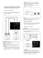
BEFORE USING THIS
UNIT
Be sure to set the voltage selector to agree with the
voltage used in the region where the unit is uesd.The
desired voltage can be easily selected by using an
ordinary screwdriver. Never forget to always have the
voltage selector set to the correct setting because, if the
setting is incorrect, this unit could be ruined by using it
an incorrect voltage.
-2-
APPLIANCES
CONNECTABLE TO THIS
UNIT
FRONT PANEL
CONTROLS AND THEIR
FUNCTIONS
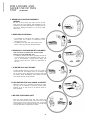
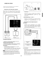
1 Power switch
This switch is used to turn the power an and off.
2 Output meter
This meter is installed to report the magnitude of speaker
output. "Left" and "Right" indicate the speakeroutputat the
left side and the right side respectively. The graduations an
the meter are gauged with respect to an 80 speaker system
such that a meter reading of "1" is 1W or a reading of "10"
is 10W. If the impedance of the speaker system is 16 Ohm,
half of the indicated value should be read. For example if
"1" is indicated, it should be read as 0.5W. Likewise if the
indication is "3" it should be read as 1.5W.
In case of 4 Ohm the read-out value corresponds to double
indicated gradation, i.e. the indicated gradation
x - 8 Ohm (Constant) Impedance
(Ohm) of available speaker
• This dB gradation is used for reproducing the frequency
test phono-disc which is needed to check the frequency
response of cartridge and channel response.
3 Tone controls
These controls are used to make adjustments of the tone
quality which may become necessary as a result of speaker
characteristics or listening room characteristics, makig it
possible to adjust the tonal quality to that most agreeable
to the listener's preference.
The bass control is for adjustment of the tone quality of the
low sound range, and the treble control is for the high
sound range.
The characteristics can be changed within a range of +12 dB
to -12 dB for the bass at 50 Hz, and within the same range
for treble at 20 kHz.
The characteristics are "flat" at the "0" position, and are
increased by turning the control to the right from the "0"
position, or decreased by turning it to the left.
4
Balance control
The left and right volume balance is influenced by the difference, if any, between the efficiency of the left and right
speakers and by the placement of the furniture in the listening room.
In addition, the left and right volume of some program
sources is not well balanced. If the control is turned further
to the left beyond the "0" position, the right sound becomes
lower. At the left position (at which the control is completely
turned to the left), the right sound cannot be heard at all,
and only the left sound is emitted.
If the control is turned to the right, the left sound becomes
lower and, at the right position (at which it is completely
turned to the right), the left sound cannot be heard at all,
and only the right sound is emitted.
5 Volume control
This control is for adjustment of the volume level.
Turning the control clockwise (maximum position is "10")
increases the volume.
Always set the volume control at "0" before turning an the
set.
6 Headphonesjack
This jack is for connection of headphones.
Use headphones with a voice-coil impedance of 4 to 16
ohms.
Note that no sound will be heard from the speakers when
headphones are connected.
7 Speaker selector
This selector is used for respectively turning an or off the
speaker systems connected.
Push it inward ( - _) to the " REMOTE ", and push it
again (_ - ) to the "MAIN".
MAIN:
To be used when listening in through the speaker system
connected to the main speaker (MAIN) terminal.
REMOTE:
To be used when listening in through the speaker system
connected to the remote speaker (REMOTE) terminal.
8 Meter range selector
This selector is used for changing over the sensitivity of the
output meter.
Push it inward ( - _) to the " x0.1", and push it again (_ to the " x 1".
x1:
The output of this unit is indicated as it is in the meter.
For example, when the output is 30 W, the pointer indicates
30 W.
x 0.1:
When the output is below 5W an the gradation, the output
must be set at this position.
The output of this unit increased by 10 times is indicated in
the meter.
For reading the actual value, reduce the indication of the
meter to 1/10.
9 High filter switch
If this switch is set to the "ON" position, treble sound which
is higher than 8 kHz is decreased with a sharp curve
characteristic of -6 dB/oct.
This switch is especially useful if there is a great
amount of phono disc "scratch" noise, tape hiss, or if
the tone quality is unsatisfactory because there is much
distortion in the treble sound of the program source.
10 Recording mode selector
This selector is used when recording from one tape deck to
another ("dubbing").
TAPE 1>2:
For recording (dubbing) from tape deck 1 to tape deck
2. SOURCE:
When recording the sound source selected by the input
selector (12), the recording can be made to both tape
deck 1 and tape deck 2 if this switch is set to this
position.
TAPE 2>1:
Tape monitoring can be performed during recording if
this switch is set to either the "TAPE 1>2" (or the
"TAPE 2>1") position.
If, during recording, the tape-minitor selector (11) is
set to the "SOURCE" position, this circuit becomes
independent and has no relationship with the Input
selector 12
For this reason, the program source
selected by the input selector (12) can be heard
without change when dubbing from tape to tape.
11 Tape-monitor selector
For playback from the tape deck connected to the "TAPE 1"
terminals, set this selector to the "TAPE 1" position.
For playback from the tape deck connected to the "TAPE
2" terminals, set it to the "TAPE 2" position.
For reproduction of the sound from the sound source
selected by the input selector 12 , set it to the
"SOURCE" position.
For recording to a trebe-head type tape deck, set it to
the "TAPE 1" (or "TAPE 2") position in order to monitor
the recorded sound just after it is recorded.
If it is set to the "SOURCE" position, the sound
immediately before recording can be heard. If, during
recording, this selector is alternately set to the "TAPE 1"
(or "TAPE 2") and "SOURCE" positions, the recordist can
confirm the condition of the recording.
12 Input selector
For selection of the input sound source.
Push it inward ( - _) to the "ON", and push it again
(_ - ) to the "OFF".
PHONO:
For record player operation.
TUNER:
For reception of broadcasts when connected with a tuner.
Note
These 2 selector are associated with each other, and
therefore, when the switch for the program source to be
played is pushed inward, other switches automatically
project outward to the "OFF".
13 Loudness switch
The loudness control compensates for "thinning out'' of the
sound. Human ears cannot perceive the low-frequency
range at low volumes, but this control compensates for
this, boosting the bass as the volume decreases. Note,
however, that if the volume control is set to a position
higher than the "5" indication, the efficiency becomes less.
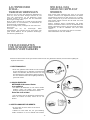
Strip away about 20 mm (3/4 inch) of the covering of
the speaker wire and twist the core wires together.
Form the core wires into the shape of a fish hook, and
attach to the connection screw.
Turn the connection screw to the right until the core
wires are securely tightened.
Do not connect the power cord until all connections
are finished. Also carefully read the operation
instructions for all equipment to be connected.
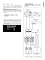
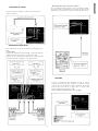
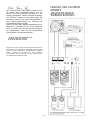
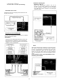
Connection of speaker systems
This unit has two pairs of speaker terminals, marked
"MAIN" and "REMOTE'', making connection of two
speaker systems possible.
NOTE:
Be extremely careful that the terminals or speaker wires do
not "short" each other. Never use the minus speaker
terminal for ground connections.
• Polarity (+) and (-) check
After the connections of the speaker systems have been
completed, confirm that the polarity of the speaker connections to the speaker terminals is correct.
Connection of a record player
• Connections
Connect the record player to the "PHONO'' terminals, being
careful to connect the left and right connection wires correctly.
If the record player has a ground wire, connect it to the
ground (GND) terminal.
• Impedance of speakers
Use speakers with a voice-coil impedance of 4-16 ohms with
this unit.
• Speaker connection wires
Use medium gauge wire. such as AC power cord, for speaker
connections so as not to decrease the damping factor. •
Connections
For perfect connections, follow the procedure shown in
figure. Note that the left terminals are for the right
channel, and the right terminals are for the left channel:
the orange terminals are
and the black terminals
are..
• Cartridge
Use a magnetic cartridge [moving-magnet type (MM),
induced-magnet type (IM), or high-output moving-coil type
(MC)] with an output of 1 mV ~ 10 mV (50 mm/sec).
If a low-output moving-coil type is used, it cannot be
connected directly to the phono terminals; a booster
transformer or head-amplifier must be used.
5
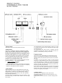
• Recording/playback terminal ("TAPE 1")
This is called the DIN connector, and is a terminal combining the functions of playback and recording. Recording and
playback are possible by simply connecting one DIN cord.
Connection of a tuner
Connect the tuner terminals of this unit with the tuner
output terminals
Connection of tape decks
Three tape decks can be connected for recording and playback.
• Connections
Connect the playback (''PLAY BACK'') terminals with the
output terminals ("LINE OUT'') of the tape deck.
Connect the recording output (''REC OUT") terminals with
the Input terminals (''LINE IN'') of the tape deck.
Groundin
If noise is heard when this amplifier is used, it may be
reduced by making a ground connection. Connect a vinylcovered wire to the ground ("GND") terminal an the rear
panel of this unit and to a copper bar or copper plate
which should be buried in the earth.
Never connect the ground wire to a gas pipe.
-6-
After preparing the tape deck for playback, increase the
volume gradually to the most comfortable listening level.
TAPE RECORDING AND
PLAYBACK
When the recording mode selector (10) is in the "SOURCE"
position, the signal which has been selected with the Input
selector 121 is constantly supplied, as a signal for recording,
from the tape deck 1 and tape deck 2 recording output terminals. In this instance, all operating controls, such as the
volume controle (5) and tone controls (3), have no effect upon
the recording.
Set the Input selector (12) according to the program
source which is to be recorded ("PHONO'', "TUNER" ).
Set the recording mode selector (10) to the ''SOURCE"
position.
Prepare the tape deck for recording.
The program which has been selected with the Input
selector (12) is then recorded onto the tape.
Be sure to adjust the recording level of the tape
deck. Recording check
The recording condition can be checked by using the tapemonitor selector il;. The sound prior to recording can be
heard from the speakers by setting the tape-monitor
selector '1 t: to the ''SOURCE'' position, and the sound
which has just been recorded can be heard from the
speakers by setting it to the appropriate ("TAPE 1" or
"TAPE 2") position.
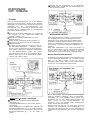
Tape "dubbing"
Tape-to-tape recording ("dubbing") from tape deck 1 to tape
deck 2, and from tape deck 2 to tape deck 1, is possible with
this unit.
The direction of the dubbing (from tape deck 1 to 2 or from
tape deck 2 to 1) is selected by using the recording mode
selector (10).
If this selector is set to the "TAPE 1>2" position, tape dubbing
from tape deck 1 to 2 is possible; if it is set to the "TAPE 2>1"
position, tape dubbing from tape deck 2 to 1 is possible.
Dubbing check:
The dubbing condition can be checked by using
monitor selector i (11) . If this switch is set to the
position the sound from tape deck 1 will be heard, if
the "TAPE 2" position, the sound from tape deck
heard.
the tape"TAPE 1''
it is set to
2 will be
Figure shows the path of the signal when a recording is
made from tape deck 1 to tape deck 2. The monitor signal
(the sound from tape deck 2 immediately after recording)
is heard from the speakers.
As shown in figure, if the tape-monitor selector 1 1; is set to
the''SOURCE'' position, the tape-to-tape recording
circuitry becomes completely independent. Accordingly,
during tape-to-tape recording, the source signal which has
been selected by the input selector (12) can be
reproduced in the same way as for ordinary operation.
Playback from a tape deck
Select the tape deck with the tape-monitor selector (c.
(The Input selector 12 has no effect in any position.)
For playback from tape deck 1,set the tape-monitor
selector (11) to the "TAPE 1" position.
For playback from tape deck 2, set the tape-monitor selector ( 1 1) to the "TAPE 2" position.
-
7
SPEAKER CIRCUIT
PROTECTION
FUSES
HOW TO CARE FOR
THE CABINET
If no sound is heard from one, or both, of the channels when
the output meters is illuminated, and if all connections for
operation have been made correctly, it is possible that the
circuit protection fuses have failed.
If so, please request the store where the unit was purchased
to check and determine whether or not the fuses have failed.
If they have failed, request the store to replace them with
new ones.
Never attempt to replace the fuses yourself, and never use
wire or any other material instead of the specified fuses
because to do so is dangerous.
If this unit becomes dirty, it can be cleaned by wiping it
with a soft, dry cloth. If it is extremely dirty, dip the soft
cloth into a soap-and-water solution, wring the cloth out
well and then wipe the unit clean. After cleaning, wipe
the unit dry once more with a dry cloth.
Be careful not to allow alcohol, thinner, benzine,
insecticide and other similar chemicals to get an the
surface of this unit because they may damage its finish
by causing the finish to peel off or lose its luster.
Never use a wet cloth or a chemically-treated cloth for
cleaning.
FOR LONGER AND
SAFER USE OF THIS
UNIT
In order to receive the best service from this unit. and for safest operation, carefully read the following
information.
1. THE POWER SOURCE:
It's very dangerous to use this unit at a voltage which is
different than the rated voltage
• There is the danger of combustion if the unit is connected to a power source which is different than
the rated voltage.
Be very careful concerning this
point. Direct current cannot be
used.
• There are some places, such as
ships, where direct current is used as
the power source. Before connecting
this unit, confirm the power source.
2. CONNECTION OF THE POWER
CORD: Wet hands are dangerous
• Be sure to never touch the power cord with wet
hands because there is the danger of electric
shock. This is true, of course, of all electric
equipment.
Don't pull the power cord
• Never pull the power cord to disconnect it. Always
pull the plug of the cord only.
3. LOCATION OF THE UNIT:
• A place which is not in direct sunlight.
• Select a place which will assure good ventilation:
at least 10 cm. from walls and other surfaces, and
where curtains or other similar material will not
obstruct the ventilation holes an its upper surface
and rear surface.
-8-
FOR LONGER AND
SAFER USE OF THIS
UNIT (continued)
4. NEVER PLACE HEATING EQUIPMENT
NEARBY
Be sure to keep stoves and other sources of heat
away from this unit, because heat radiated by such
equipment may cause deformation of plastic parts of
this unit or damage its cabinet, or, at worst, might
cause a fire.
5. KEEP INSECTICIDE AWAY
• If insecticide is sprayed an the cabinet or plastic
parts of this unit, "cracks" or "cloudiness" of the
material may occur.
• In addition, note that such sprays may be the
cause of fire, so great care should be taken.
6. ESPECIALLY FOR FAMILIES WITH CHILDREN
Take care that no small items, such as metal
articles, are put inside this unit
• In addition, children should be especially warned not
to put anything into the ventilation holes, such as
toys or a screwdriver, because these things may
cause an electric shock or result in a malfunction of
the unit.
7. IF WATER SPILLS ON THE UNIT
If water should happen to spill an the unit, from an
overturned vase for example, there is the danger of
fire or electric shock. Disconnect the power cord from
the electric outlet immediately, and contact the store
from which the unit was purchased.
B. RECONSTRUCTION CAN CAUSE ACCIDENTS
Absolutely never try to remodel, reconstruct or repair
this unit. Do not attempt to touch any internal parts
because to do so may result in an electric shock or
other accident.
9. BE SURE THE POWER IS OFF
After you have finished using this unit, check once
more to be sure that the power is off. If the unit is left
with its power an for a long period of time, it may not
only damage the unit and thus shorten its useful life,
but may also lead to a dangerous accident.
-9-
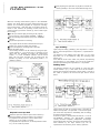
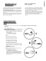
HOW TO USE PIN PLUGS
Use the furnished pin plug when the connection terminal (pin
jack) of this unit is different in shape from the connecting cord of
the Set to be connected to this unit.
Intermodulation distortion
0.08% (60 Hz : 7 kHz=4 : 1, SMPTE)
Residual hum and noise
0.6 mV
Damping factor
20 (4 Ohm), 40 (8 Ohm)
Input sensitivity and impedance
PHONO
2,5 mV/47 kOhm
TUNER
150 mV/47 kOhm
PLAYBACK TAPE 1
180 mV/47 kOhm
PLAYBACK TAPE 2
150 mV/47 kOhm
REC / PLAY TAPE 1
180 mV/47 kOhm
PHONO maximum Input voltage (1 kHz, RMS) 150 mV
Signal to noise ratio (IHF, A)
PHONO
78 dB
TUNER
97 dB
Frequency response
PHONO
RIAA Standard curve +-0.3dB
TUNER
7 Hz-80 kHz,+0 d8, -3 dB 20
Hz-20 kHz, +-0.5 dB
Tone controls
BASS
50 Hz, +12 dB- -12 dB
TREBLE
20 kHz, +12 dB- -12 dB
High filter
8 kHz, -6 dB/oct.
Loudness control (volume at -30 d8)
100 Hz, +8 dB
Output voltage and impedance
REC OUT TAPE 1, TAPE 2
150 mV/1.2 kOhm
REC/PLAY TAPE 1
30 mV/82 kOhm
Load impedance
MAIN or REMOTE
4--16 Ohm
(DIN 45 500)
1 kHz continuous power
both channels driven
2X55W (4Ohm)
2X43 W (8Ohm)
20 Hz~20 kHz continuous power
both channels driven
ACCESSORIES
Circuit protection fuses .............................................. 2
Pin plugs ................................................................4
TECHNICAL
SPECIFICATIONS
Amplifier section
(IHF)
1 kHz continuous power
both channels driven
55 W+55 W (4S2) 43 W+43 W (8 Ohm)
20 Hz~20 kHz continuous power
both channels driven 48 W+48 W (4 Ohm) 41 W+41 W (8 Ohm)
Power bandwidth (both channels
driven at 8 Ohm)
8 Hz~55 kHz, -3 dB
Total harmonic distortion
0.08% at rated power (20 Hz--20 kHz) 0.04 % at half power (20
Hz-20 kHz) 0.02% at half power (1 kHz)
40 Hz~16 kHz continuous power
both channels driven
2X48 W (4 Ohm)
2X41 W (8 Ohm)
2X48 W (4 Ohm) 2X41 W
(8Ohm)
Power bandwidth
both channels driven at 4 Ohm
8 Hz-55 kHz, -3 dB
Total harmonic distortion
rated power at 1 kHz, 4 Ohm
0.08%
rated power at 40 Hz~16,000 Hz, 4 Ohm
0.08%
-26 dB rated power at 1 kHz, 4 Ohm
0.1
50 mW power at 1 kHz, 4S2
0.15%
Intermodulation distortion
rated power at 250 Hz: 8,000 Hz=4:1, 4 Ohm
0.08%
Frequency response
7
Hz~80 kHz, +0 dB, -3 dB 15 Hz~40 kHz, +0 d8, -1 dB
Signal to noise ratio
rated power
50 mW power
PHONO,
TUNER
Channel balance
Channel Separation Headphones level
and output impedance
63dB
83dB
55dB
58dB
53dB
±1.5dB
50 dB
350 mV/330 Ohm
General
Power consumption
Power supply (50 Hz/60 Hz)
Dimensions (WxHxD)
Weight
400 W
110 V/120 V/220 V/240 V
410x139X334 mm
8.9 kg
GERÄTE, DIE AN DIESE
EINHEIT
ANGESCHLOSSEN
WERDEN KÖNNEN
Wir möchten Ihnen dafür danken, dass Sie sich
für dieses Gerät entschieden haben, und wir
heissen Sie hiermit herzlich willkommen in der
ständig wachsenden Familie zufriedener Besitzer
von "Technics" Geräten in der ganzen Welt. Wir
sind sicher, dass Sie mit dieser Neuerwerbung zu
Ihrer Wohnungseinrichtung ein Optimum an
Klangqualität erzielen werden.
Lesen Sie bitte diese Bedienungsanleitung sorgfältig durch, und halten Sie sie immer griffbereit,
denn sie enthält eine Anzahl wichtiger Hinweise,
die gewährleisten, dass Sie die Möglichkeiten
Ihres Gerätes voll ausnutzen können.
VOR DEM ERSTEN
EINSCHALTEN
Vergwissern Sie sich, daß der Spannungswahlschalter auf die
örtliche Spannung eingestellt ist. Die richtige Spannung kann
leicht mit einem gewöhnlichen Schraubenzieher eingestellt
werden. Vergessen Sie auf keinen Fall, diese Einstellung
vorzunehmen, denn der Betrieb mit der falschen Spannungseinstellung zerstört das Gerät.
11
REGLER DER
GERÄTEVORDERSEITE
UND IHRE FUNKTIONEN
Netzschalter
Dieser Schalter wird dazu benutzt, den Strom an- und
abzuschalten.
Ausgangspegelmeter
Dieser Pegelmeter zeigt die Stärke des Signals von den
Lautsprecherausgängen an. "Left" und "Right" beziehen
sich auf die Lautsprecherausgänge (auf der linken, resp.
der rechten Seite. Die Graduierung der Skala ist auf ein
Lautsprechersystem von 8 Ohm abgestimmt, sodaß eine
Meteranzeige von "1" 1W und eine solche von "10" 10W
entspricht. Falls die Impedanz des Lautsprechersystems
16 Ohm beträgt, so ist der effektive Watt-Wert die Hälfte
des angezeigten Wertes. Falls der angezeigte Pegel "1"
beträgt so entspricht dies einem Wert von 0.5W; oder falls
der Meßwert "3"" ist, so entspricht dies einem Wert von
1,5W.
Bei 4 4 Ohm entspricht der Meßwert dem Doppelten des
angezeigten Skalawertes, d.h. angezeigter Skalawert
8 Ohm (konstant) Impedanz (Ohm) des
Lautsprechers Diese dB-Skala wird zur Wiedergabe der
Frequenztestplatte verwendet, welche zum Kontrollieren
des Frequenzgangs des Tonabnehmers und der
Kanaltrennung benötigt wird.
Tieftonbereich und die Regler für die Höhen sind für den
Hochtonbereich vorgesehen.
Die Charakteristiken können im Bereich von +12 dB bis -12
d8 für die Bässe bei 50 Hz und im Bereich von +13 dB bis
13 dB für die hohen Töne bei 20 kHz verändert werden. Die
Charakteristik ist "abgeflacht" in der ''0" -Stellung und sie
erhöht sich bei Drehung von der ''0" Stellung nach rechts
oder erniedrigt sich bei Drehung nach links.
Balanceregler
Die linke und rechte Lautstärkebalance wird beeinflußt von
der eventuellen Differenz, zwischen der Leistung des linken
und des rechten Lautsprechers und von der Anordnung der
Möbel im Raum.
Außerdem ist die linke und die rechte Lautstärke einiger
Programmquellen nicht exakt ausgeglichen. Wenn man den
Regler über die "0"-Stellung hinaus weiter nach links dreht,
wird der rechte Klang leiser. Bei der "left-"Stellung (in der
Regler vollständig nach links gedreht wird), kann man den
rechten Klang überhaupt nicht mehr hören und nur der linke
Klang wird ausgestrahlt.
Wird der Regler nach rechts gedreht, so wir der linke
Klang leiser und auf der ''right"-Stellung (auf der er völlig
nach rechts gedreht wird) kann der linke Klang überhaupt
nicht mehr gehört werden und nur der rechte Klang wird
ausgestrahlt.
Lautstärkeregler
Tonregler
Diese Regler werden zur Einstellung der Tonqualität benutzt, was nötig werden kann infolge von Lautsprechereigenschaften oder Charakteristiken des Raumes, in dem
Sie hören. Diese Regler ermöglichen die Einstellung der
Tonqualität, die für den Hörer am angenehmsten ist.
Die Baßregler sind für die Einstellung der Tonqualität im
Bringen Sie bitte den Lautstärkeregler auf eine
angenehme Hörstufe.
Durch Drehen des Knopfes im Uhrzeigersinn (Maximal:
"10") vergrößert sich die Lautstärke.
Stellen Sie immer die Lautstärkeregelung auf ''0'' bevor
Sie das Gerät einschalten.
-12-
SOURCE:
REGLER DER
GERATEVORDERSEITE
UND IHRE FUNKTIONEN
Beim Aufnehmen von der Tongquelle, die mit dem
Eingangswählschalter (12) eingestellt wurde, kann die
Aufnahme sowohl auf das Tonbandgerät 1 als auch auf
das Tonbandgerät 2 gemacht werden, wenn dieser
Schalter in der Position "SOURCE" steht.
(Fortsetzung)
TAPE 2>1
Ohrhörer-Buchse
Diese Buchse dieut zum Anschließen eines Kopfhörers.
Benutzen Sie bitte Kopfhörer mit einem Widerstand von 4
bis 16 Ohm
Beachten Sie, daß aus den Lautsprechern kein Ton gehört
werden kann, wenn die Kopfhörer angeschlossen sind.
Lautsprecher-Wählschalter
Dieser Schalter wird dazu verwendet, um die angeschlossenen Lautsprechersysteme ein- oder auszuschalten.
Drücken Sie die Drucktaste für " REMOTE " ein ( - _),
und drücken sie nochnals, damit sie für " MAIN " in die
vorstehende Stellung zurückkehrt
MAIN
Wird verwendet, wenn durch das an den Hauptlautsprecheranschluß (MAIN) angeschlossene Lautsprechersystem
gehört wird.
REMOTE:
Wird verwendet, wenn durch das an den Entfernte Lautsprecheranschluß (REMOTE) angeschlossene Lautsprechersystem gehört wird.
Meßbereich-Wählschalter
Dieser Schalter wird verwendet, um die Empfindlichkeit des
Ausgangsmeters umzuschalten.
Drücken Sie die Druckttase für " x0.1" ein (
- _), und
drücken Sie nochmals, damit sie für " x 1" in die vorstehende Stellung zurückkehrt (_ - ).
x1:
Die Ausgangsleistung dieses Gerätes entspricht dem im
Meter angezeigten Wert.
Berägt die effektive Ausgangsleistung z.B. 30 W, so ist der
angezeigte Wert 30 W.
x0.1:
Wenn die Ausgangsleistung auf der Meßskala unter 5W
liegt, so muß der Ausgang auf diesen Wert eingestellt
werden.
Die Ausgangsleistung dieses Gerätes multipliziert mit 10
entspricht dem im Meter angezeigten Wert.
Der effektive Wert ist 1/10 des im Meter angezeigten
Wertes.
Zum Aufnehmen (Überspielen) vom Tonbandgerät 2 auf
Tonbandgerät 1.
Die Aufnahme kann mitgehört werden, wenn dieser
Schalter entweder in der "TAPE 1>2" oder der "TAPE
211"-Posilion ist.
Falls der Bandmithör-Wählschalter (11) während der
Aufnahme in die "SOURCE"-Position gebracht wird, so
wird diese Schaltung unabhängig und hat keine
Beziehung zum Eingangswählschalter (12)
Aus diesem Grund kann die Tonquelle, die mit dem Eingangswählschalter
(12)
gewählt
wurde,
beim
Überspielen von einem Tonbandgerät zu einem andern
unverändert gehört werden.
I Bandmithör-Wählschalter
Für die Wiedergabe vom Tonbandgerät 1, das an die Anschlüsse für das Tonbandgerät 1 angeschlossen ist,
stellen Sie den Schalter in die Position "TAPE 1".
Für die Wiedergabe vom Tonbandgerät 2, das an die
Anschlüsse für das Tonbandgerät 2 angeschlossen ist,
stellen Sie ihn in die Posilion "TAPE 2".
Für die Wiedergabe von Ton von einer Tonquelle, die mit
dem Eingangswählschalter (12) gewählt wurde, stellen
Sie den Bandmithör-Wählschalter in die Position
"SOURCE". Wenn Sie ein Tonbandgerät mit 3-KopfSystem verwenden, kann der soeben aufgenommene
Ton mitgehört werden, indem Sie den Wählschalter in
die "TAPE 1" (oder "TAPE 2")-Position stellen.
Steht er in der "SOURCE"-Position so kann der Ton
unmittelbar vor der Aufnahme gehört werden. Wenn
dieser
Schalter
während
der
Aufnahme
abwechslungsweise in die "TAPE V' (oder "TAPE 2") und
"SOURCE"-Position gestellt wird, kann man sich über den
Stand der Aufnahme vergewissern.
I Eingangswählschalter
Zum Auswählen der Eingangstonquelle.
Drücken Sie die Drucktaste für "ON" ein
und drücken sie nochnals, damit sie für "OFF" in die vorstehende Stellung zurückkehrt
PHONO:
Zum Hören vom Plattenspieler.
Hochtonfilter-Schalter
TUNER:
Wenn dieser Schalter auf der "ON"-Stellung steht, werden
die Höhen, die höher sind als 8 kHz vermindert mit einer
Flankensteilheit von -6 dB/oct.
Dieser Schalter ist besonders nützlich, wenn viel Kratzgeräusche auf Schallplatten oder Bandrauschen auftreten,
oder wenn die Tonqualität nicht zufriendenstellend ist, weil
in den hohen Klängen der Programmquelle große Verzerrungen vorkommen.
ANMERKUNG:
Für den Radioempfang bei Anschluß an einen Tuner.
I Aufnahme-Wählschalter
Dieser Schalter wird beim Aufnehmen von einem Tonbandgerät zu einem anderen Tonbandgerät verwendet
("dubbing").
TAPE 1>2:
Zum Aufnehmen (Überspielen) von Tonbandgerät 1 auf
-13-
Diese 2 Schalter sind miteinander gekoppelt.
Wenn der Schalter für die abzuspielende Programmquelle
gedrückt wird, so springen die anderen Schalter automatisch
in die "OFF"-Position.
Lautstärkekontroll-Schalter
Im allgemeinen kann das menschliche Ohr den Bereich
der Bässe bei sehr niedriger Lautstärke nicht erfassen.
Der Lautheitsregler (Loudnessregler) dient zur Verbesserung dieser Lage. Der Baßbereich wird betont, wenn
dieser Regler eingeschaltet und der Lautstärkeregler auf
eine niedrige Stellung gestellt wird.
Beachten Sie jedoch, daß die Leistung schwächer wird,
wenn der Lautstärkeregler auf einer Stellung höher als
"5" steht.
ANSCHLÜSSE
Stecken Sie nicht den Netzstecker ein, bevor Sie alle
anderen Anschlüsse hergestellt haben.
Anschliessen von Lautsprecher-Systemen
Diese Einheit hat zwei Paare Lautsprecherbuchsen, die mit
"MAIN" (Haupt-) und "REMOTE" (Fern-) gekennzeichnet
sind und den Anschluß von zwei Lautsprechersystemen
gestatten.
Anmerkung:
Beachten Sie, daß die Anschlüsse der Lautsprecher
nicht kurz geschlossen werden. Benutzen Sie den
Minus-Lautsprecheranschluß
nicht
für
den
Erdanschluß.
•Polaritätsprüfung «+) und C )
Nachdem die Anschlüsse der Lautsprechersysteme
durchgeführt wurden, vergewissern Sie sich, ob die
Polarität
der
Lautsprecheranschlüsse
an
den
Anschliessen eines Schallplattenspielers
•Anschlüsse
Schließen Sie den Plattenspieler an die "PHONOBuchse an und achten Sie darauf, daß Sie die linken
und die rechten Anschlußdrähte richtig einstöpseln.
Falls der Plattenspieler ein Erdungskabel hat, verbinden
Sie es bitte mit dem GNDAnschluß.
/Lautsprecherimpedanz
Benutzen Sie Lautsprecher mit einer Schwingspulenimpedanz von 4-16 Ohm für diese Anlage.
•Lautsprecheranschlusskabel
Benutzen Sie ein Kabel von mittlerer Stärke, zum Beispiel
ein Wechselstromnetzkabel, für die Lautsprecheranschlüsse,
um die Dämpfungskonstante nicht herabzusetzen.
•Anschlüsse
Um alle Anschlüsse richtig durchzuführen, folgen Sie
bitte den Anleitungen in Abbildung.
Die linken Anschlüsse sind für den rechten Kanal und die
rechten Anschlüsse für den linken Kanal; die roten Anschlüsse sind (-) und die schwarzen Anschlüsse sind
•Tonabnehmer
Benutzen Sie ein magnetisches Tonabnehmersystem [beweglicher Magnet (MM), induzierter Magnet (IM) und bewegliche Spule (MC)]. mit einer Leistung von 1 mV-10 mV
(50 mm/s).
Ein MC-Tonabnehmer niedriger Ausgangsleistung kann
nicht direkt mit Phono-Buchsen verbunden werden. Benutzen Sie in diesem Fall einen Zusatztransformator oder
einen Tonkopfverstärker.
Entfernen Sie etwa 20 mm der Isolation des Lautsprecherkabels und verdrillen Sie die Kabelseele.
Biegen Sie die freie Kabelseele in Form eines Hakens
und führen Sie ihn zwischen Gerät und Schraube ein.
Drehen Sie die Anschlußschraube nach rechts, bis die
Kabelseele fest angezogen sitzt.
-15-
•Aufnahme-/WiedergabeAnschluß ("TAPE V')
Dieser wird DIN-Anschluß genannt und ist ein
Anschluß, der die beiden Funktionen der Wiedergabe
und der Aufnahme verbindet, Durch den Anschluß
eines DIN-Kabels können Aufnahme und Wiedergabe
vereinfact werden.
ANSCHLÜSSE (Fortsetzung)
Anschließen eines Tuners
Verbinden Sie den Tuner-Eingang dieses Gerätes mit dem
Ausgang Ihres Tuners.
Anschliessen eines Tonbandgeräts
Es könne drei Tonbandgeräte zum Aufnehmen und Wiedergeben angeschlossen werden.
•Anschlüsse
Verbinden Sie die Wiedergabe-Anschlüsse mit den Ausgangs-Anschlüssen ("LINE OUT'') Ihres Tonbandgerät.
Verbinden Sie die Aufnahmeausgänge mit dem Eingang
("LINE IN'') Ihres Tonbandgerät.
Erden
Sollte beim Betrieb dieses Verstärkers ein Rauschen hörbar
sein, kann es durch Erden vermindert werden. Verbinden
Sie einen vinylverkleideten Leitungsdraht mit einem Ende
mit dem Erdanschluß (''GND'') auf der Rückseite dieses
Geräts und mit dem anderen Ende mit einem Kupferstab
oder einer Kupferplatte, die in die Erde eingegraben werden
sollten.
Es ist gesetzlich verboten, das Erdungskabel an eine
Gasleitung anzuschließen.
-15-
WIEDERGABE
VOM TONBAND
Nachdem Sie das Tonbandgerät für die Wiedergabe
vorbereitet haben, bringen Sie den Lautstärkeregler auf
eine angenehme Hörstufe.
Aufnahme
Wenn der Aufnahme-Wählschalter (10) in der "SOURCEPosition steht, wird das Signal, welches mit dem EingangsWählschalter (12) gewählt wurde, fortlaufend als Signal zum
Aufnehmen
von
den
Ausgangsanschlüssen
der
Tonbandgeräte 1 und 2 gespiesen. In diesem Falle haben
alle Regler, wie z.B. Lautstärkeregler (5) und Klangregler
keinen Einfluß auf die Aufnahme.
Stellen Sie den Eingangs-Wählschalter (12) entsprechend
der Tonquelle, von der aufgenommen werden soll
(''PHONO ", "TUNER", ) ein.
Stellen Sie den Aufnahme-Wählschalter (10) in die
"SOURCE"-position.
Bereiten Sie das Tonbandgerät auf die Aufnahme vor.
Regulieren Sie das Aufnahmeniveau am Tonbandgerät.
Aufnahmekontrolle
Der Stand und die Qualität der Aufnahme können mit
dem Bandmithör-Wählschalter (; überwacht werden.
Der Ton vor der Aufnahme kann durch die Lautsprecher
gehört werden, indem Sie den Bandmithör-Wählschalter
(
11) die "SOURCE"-Position stellen. Der soeben
aufgenommene Ton kann durch die Lautsprecher gehört
wderden, indem Sie ihn in die entsprechende Position
("TAPE 1" oder "TAPE 2") stellen.
Wiedergabe von einem Tonbandgerät
Wählen Sie das Tonbandgerät mit dem BandmithörWählschalter (11) .
(Der Eingangswählschalter (12) hat in keiner Stellung
einen Einfluß.)
Für die Wiedergabe vom Tonbandgerät 1, stellen Sie den
Bandmithör-Wählschalter (11) in die "TAPE 1"-Position.
Für die Wiedergabe vom Tonbandgerät 2, stellen Sie den
Bandmithör-Wählschalter (11)
in die "TAPE 2"Position.
Band-zu-Band Aufnahme
Band-zu-Band Aufnahmen ("dubbing") vom Tonbandgerät 1
zum Tonbandgerät 2 und vom Tonbandgerät 2 zum Tonbandgerät 1 können mit dem SU-7300 hergestellt werden.
Die Richtung der Band-zu-Band Aufnahme (vom Tonbandgerät 1 zum Tonbandgerät 2 oder vom Tonbandgerät 2 zum
Tonbandgerät 1) wird mit dem Aufnahme-Wählschalter (10)
bestimmt.
Steht dieser Wählschalter in der "TAPE 1(12"-Position, so
kann vom Tonbandgerät 1 auf das Tonbandgerät 2 überspielt
werden; ist er in der "TAPE 2•1"-Position, so kann vom
Tonbandgerät 2 auf das Tonbandgerät 1 überspielt werden,
Band-zu-Band Aufnahmekontrolle:
Die Qualität und der Stand der Band-zu-Band Aufnahme kann
mit dem Bandmithör-Wählschalter (11) i) kontrolliert werden
Steht er in der "TAPE 1"-Position, so kann Ton vom Tonbandgerät 1 gehört werden; steht er in der "TAPE 2"Position,
so kann Ton vom Tonbandgerät 2 gehört werden.
Wie in Abb. gezeigt, wird die Band-zu-Band Aufnahmeschaltung vollständig unabhängig, wenn der BandmithörWählschalter (11) in die "SOURCE''-Position gestellt wird.
Desgleichen kann bei einer Band-zu-Band Aufnahme das
Signal, welches mit dem Eingangs-Wählshalter (12)
ausgewählt wurde, auf dieselbe Weise wiedergegeben
werden, wie bei normalem Betrieb.
Abbildung zeigt den Weg, den ein Signal geht, wenn eine
Aufnahme vom Tonbandgerät 1 zum Tonbandgerät 2 gemacht wird. Das Mithörsignal (der Ton vom Tonbandgerät 2
unmittelbar nach der Aufnahme) wird durch die Lautsprecher
gehört.
LAUTSPRECHER
SCHALTKREISSICHERNNGEN
WIE SOLL DAS
GEHÄUSE GEPFLEGT
WERDEN
Wenn kein Ton von einem oder beiden der Absatzwege zu
hören ist, wenn der Strom Anzeiger belichtet ist, und
wenn alle Verbindungen für die Bedienung richtig
gemacht wurden, ist es möglich das die Kreisschutz
Sicherungen versagt haben.
Wenn so, bitte verlangen Sie im Laden wo Sie das Gerät
gekauft haven, es zu kontrollieren, um festzustellen ob
die Sicherungen versagt haben.
Wenn sie versagt haven, verlangen Sie vom Laden neue
Sicherungen.
Versuchen
Sie
nie,
die
Sicherungen
selber
auszuwechseln, und brauchen Sie nie einen Draht, oder
jedes andere Material, als die speziellen Sicherungen,
weil das sehr gehährlich ist.
Wenn dieses Gerät schmutzig wird, kann es mit einem
weichen, trockenen Tuch abgewischt werden. Bei starker
Verschmutzung tauchen Sie das weiche Tuch in Seifenwasser, wringen Sie es gut aus und wischen Sie dann das
Gerät sauber. Danach trocknen Sie das Gerät mit einem
trockenen Tuch ab.
Alkohol, Verdünner, Benzin, Insektenspray und andere
ähnliche Chemikalien sollten nicht mit der Oberfläche des
Geräts in Berührung kommen, denn sie können die Politur
beschädigen, so daß sie abblättert oder ihren Glanz
verliert.
Verwenden Sie nie ein nasses Tuch oder ein mit Chemikalien behandeltes Tuch zum Säubern.
FÜR DAUERHAFTEN
UND SICHEREN BETRIEB
DIESES VERSTÄRKERS
Damit Ihnen dieses Gerät immer gute Dienste leistet und für den gefahrlosen Betrieb, lesen Sie bitte sorgfältig die
folgende Information.
1. DIE STROMQUELLE:
• Es ist sehr gefährlich dieses Gerät bei einer anderen
als der Nennspannung zu betreiben. Es besteht die
Gefahr eines Brandes, falls das Gerät bei einer von
der Nennspannung verschiedenen Spannung betrieben wird. Diesem Punkt sollte sorgfältige Beachtung
geschenkt werden.
2. ANSCHLIESSEN DES
NETZKABELS: Mit nassen Händen
ist es gefährlich
• Sie sollten das Netzkabel nie mit nassen Händen
anfassen wegen der Gefahr eines elektrischen
Schlages. Dies gilt für alle elektrischen Geräte.
Ziehen Sie nicht an Kabel
• Um den Stecker aus der Steckdose herauszuziehen,
ziehen Sie niemals am Kabel, ziehen Sie nur am
Stecker.
3. AUFSTELLUNGSORT DES GERÄTS:
• An einem Ort, der nicht direkt von der Sonne
bestrahlt wird.
• Wählen Sie einen Platz aus, der gute Belüftung
zuläßt: mindestens 10 cm von Wänden oder anderen
17
4. STELLE SIE KEINE HEIZGERÄTE IN
UNMITTELBARE NÄHE:
Halten Sie Heizöfen oder andere Heizquellen von
diesem Gerät fern, denn die abgestrahlte Hitze könnte
die Plastikteile verformen oder die Verkleidung
beschädigen oder im schlimmsten Fall einen Brand
auslösen.
5. HALTEN SIE INSEKTENBEKÄMPFUNGSMIT
TEL FERN:
• Wenn ein Insektenspray auf die Verkleidung oder die
Plastikteile des Verstärkers gesprüht wird, können
"Risse" oder eine "Trübe" auftreten.
• Außerdem" sind solche Sprays entzündlich, es ist
deshalb größte Vorsicht geboten.
6. BESONDERER HINWEIS FÜR FAMILIEN MIT
KINDERN:
Treffen Sie Vorkehrungen, daß keine kleinen
etwa metallische Gegenstände in das Gerät
weden
• Die elektrischen Anschlußstecker auf der Rückseite
stellen eine Hochspannungsquelle dar. Seien Sie
unbedingt achtsam, daß keine Gegestände wie
Nadeln, Haarklammern, u.s.w. dort hineingesteckt
werden.
7. WENN WASSER AUF DEM GERÄT
VERSCHÜTTET WIRD:
Sollte einmal Wasser auf dem Gerät verschüttet
werden, z.B. aus einer umgestürzten Blumenvase, dann
besteht die Gefahr eines Kurzschlusses und eines
Feuers. Ziehen Sie sofort den Netzstecker heraus und
benachrichtigen Sie das Fachgeschäft, bei dem Sie das
Gerät kauften.
B. SELBST AUSBESSERN KANN ZU UNFÄLLEN
FÜHREN:
Versuchen Sie auf keinen Fall an diesem Gerät etwas
nachzugestalten, zu erneuern oder zu reparieren. Versuchen Sie auch nicht, Teile im Innern zu berühren,
denn das könnte zu einem elektrischen Schlag oder
einem anderen Unfall führen.
9. VERGEWISSERN SIE SICH, DASS DER
STROM ABGESCHALTET IST
Nachdem Sie den Betrieb dieses Verstärkers beendet
haben, prüfen Sie nach, daß Sie auch gewiß den Strom
abgeschaltet haben. Wenn das Gerät über einen längeren Zeitraum angeschaltet gelassen wird, leidet möglicherweise nicht nur das Gerät, so daß sich seine
Lebensdauer verkürzt, sondern es könnte auch zur
Ursache gefährlicher Unfälle werden.
VERWENDUNG VON
MINI-STECKERN
Hum & Noise
0.6 mV
Dämpfungsfaktor
20 (4 Ohm), 40 (8 Ohm)
Eingangsempfindlichkeit & Impedanz
PHONO
2.5 mV/47 kOhm
TUNER
150 mV/47 kOhm
PLAYBACK TAPE 1
180 mV/47 kOhm
PLAYBACK TAPE 2
150 mV/47 kOhm
REC/PLAY TAPE 1
180 mV/47 kOhm
PHONO Maximale Eingangsspannungen
(1 kHz, RMS)
150 mV
Fremdspannungsabstand (IHF, A)
PHONO
78dB
TUNER
97 dB
Frequenzgang
PHONO
RIAA Standardkurve +-0.3 dB
TUNER
7 Hz-80 kHz, - 0 dB, -3 dB
20 Hz-20 kHz, +0.5 dB
Klangregler
BÄSSE
50 Hz, +12 dB--12 dB
HÖHEN
20 kHz, +12 dB~-12 dB
Hochtontilter
8 kHz, -6 dB/oct.
Gehörgerechte Lautstärkekorrektur (Lautstärke -30 dB)
100 Hz, +8 dB
Verwenden Sie den mitgelieferten Mini-Stecker, falls die Form des
Anschlußes (Steckerbuchse) dieses Gerätes verschieden vom
Anschlußkabel der anzuschließenden Einheit ist.
100 Hz, +8 dB
Ausgangsspannungen
REC OUT TAPE 1, TAPE 2
REC/PLAY TAPE 1 Aufnahme
Endimpedanz
MAIN oder REMOTE
150 mV/1.2 kOhm
30 mV/82 kOhm
4-16 Ohm
(DIN 45 500)
RMS-Dauertonleistung bei 1 kHz
beide Kanäle zusammen ausgesteuert
2X55 W (4 Ohm)
2X43 W (8 Ohm)
RMS-Dauertonleistung bei 20 Hz~20 kHz
beide Kanäle zusammen ausgesteuert
ZUBEHÖR
2x 41 W (8)
RMS-Dauertonleistung bei 40 Hz~16 kHz
2 x 48 W (4Ohm)
beide Kanäle zusammen ausgesteuert
2 x 41 W (8 Ohm)
Leistungsbandbreite (beide Kanäle zusammen
ausgesteurt bei 452)
8 Hz~55 kHz, -3 dB
Harmonische Verzerrungen
Nennleistung bei 1 kHz, 4Ohm
0.08%
Nennleistung bei 40 Hz Ohm 16,000 Hz, 4Ohm
0.08%
-26 dB Ausgangsleistung 1 kHz, 4Ohm
0.1 %
50 mW Ausgangsleistung 1 kHz, 4 Ohm
0.15%
Intermodulationsverzerrung
Nennleistung bei 250 Hz: 8,000 Hz=4:1, 4Ohm
0.08%
Frequenzgang
7 Hz~80 kHz, +0 dB, -3 dB
15 Hz~40 kHz, +0 dB, - 1 dB
Kurzschlußsicherungen ............................................. 2
Mini-Stecker ............................................................. 4
TECHNISCHE DATEN
Fremdspannungsabstand
Nennleistung PHONO
TUNER
-26 dB Ausgangsleistung
PHONO
TUNER
50 mW Ausgangsleistung PHONO, TUNER
Verstärkerteil
(IHF)
RMS-Dauertonleistung bei 1 kHz
beide Kanäle zusammen ausgesteuert
RMS- Dauertonleistung bei 20 Hz~20 kHz
beide Kanäle zusammen ausgesteuert
2x 48 W (4Ohm)
55 W+55 W (4 Ohm)
43 W+43 W (8Ohm)
Kanaltrennung
Kanalabweichung
Kopfhörerpegel und
Ausgangsimpedanz
48 W+48W (4 Ohm)
41 W+41 W (8Ohm)
Leistungsbandbreite
(beide Kanäle ausgesteuert bei 8 Ohm)
8 Hz~55 kHz, -3 dB
Harmonische Verzerrung
0.08% bei Nennleistung (20 Hz~20 kHz)
0.04% bei Halbwertleistung (20 Hz~20 kHz)
0.02% bei Halbwertleistung (1 kHz)
Intermodulations Verzerrung
0.08% (60 Hz: 7 kHz=4:1, SMPTE)
63
83
55
58
53
dB
dB
dB
dB
dB
+-1.5dB
50 dB
350 mV/330 Ohm
Allgemeine Daten
Leistungsaufnahme
400 W
Netzspannung umschaltbar (50 Hz/60 Hz)
110 V/120 V/220 V/240 V
410x139x334 mm 8.9 kg
Abmessungen (B x H x T)
Gewicht
-19-