1
DVA M2M
DVA M2S
DESIGNED & DEVELOPED IN ITALY
MANUALE D’USO - Sezione 1
USER MANUAL - Section 1
BEDIENUNGSANLEITUNG - Abschnitt 1
CARACTERISTIQUES TECHNIQUES - Section 1
Le avvertenze nel presente manuale devono essere osservate congiuntamente al “MANUALE D’USO - Sezione2”.
The warnings in this manual must be observed together with the "USER MANUAL - Section 2".
Die Warnungen in diesem Handbuch müssen in Verbindung mit der "BEDIENUNGSANLEITUNG - Abschnitt 2" beobachtet werden.
Les avertissements dans ce manuel doivent être respectées en collaboration avec le "CARATTERISTIQUES TECHNIQUES - Section 2".
ITALIANO
DVA MINI Digital Array System
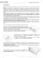
DESCRIZIONE
I diffusori DVA M2M e DVA M2S fanno parte del sistema componibile e modulare denominato DVA
MINI.
Il sistema è utilizzabile in configurazione in appoggio a terra (ground stack) oppure appeso in
configurazione line-array. I moduli utilizzano un metodo di fissaggio meccanico veloce e innovativo.
Questa serie risulta ideale per installazioni in teatri, luoghi di culto, centri congressi, concerti e
spettacoli di musica dal vivo dove sono richieste pressioni sonore medio-elevate e pesi ed ingombri
ridotti.
Il DVA M2M è equipaggiato con due amplificatori in classe D della serie DIGIPRO® G3 in grado di
pilotare anche il diffusore DVA M2S grazie a un cablaggio semplice e immediato.
Il modulo amplificatore è in grado di erogare 400W RMS (totali), 200W RMS per la sezione dei
bassi e 200W (RMS) per la sezione degli alti.
L’alta efficienza dei moduli DIGIPRO® G3 permette di ottenere elevate potenze di uscita con pesi
ed ingombri ridotti. Grazie alla sua bassa potenza dissipata, il raffreddamento del modulo
amplificatore avviene in modo statico, evitando l’impiego di ventole.
Il preamplificatore digitale con DSP (Digital Signal Processor) gestisce i componenti acustici, la
risposta in frequenza, il limiter e le segnalazioni del diffusore.
La PSU (Power Supply Unit) SMPS (Switched-Mode Power Supply) grazie alla tecnologia autorange garantisce il funzionamento a tensioni di alimentazioni da 100V~ a 120V~ e da 220V~ a
240V~.
Tutte e due i diffusori sono dotati dei medesimi componenti acustici.
La sezione dei bassi è composta da due woofer da 6,5” al neodimio
(voice coil 1,5”). Il doppio phase plug presente davanti ad ogni
singolo cono avvicina il punto di immissione acustica del woofer
evitando la sovrapposizione di fase orizzontali.
Il disegno dei phase plug è stato progettato appositamente per il
corretto accoppiamento con i diffusori della serie DVA MINI.
La sezione degli alti è composta due compression driver da 1” al
neodimio (voice coil 1”) montati verticalmente e distanziati per
ottimizzare la copertura verticale.
La tromba è stata disegnata appositamente per il corretto
accoppiamento dei diffusori della serie DVA MINI.
Il DVA M2M e DVA M2S sono realizzati in polipropilene con due maniglie laterali posteriori per
facilitare il trasporto e l’installazione. I diffusori sono equipaggiati con staffe in acciaio ed un facile e
semplice sistema di bloccaggio.
La staffa posteriore è graduata (0°-1,5°-3°-4,5°-6°-8°-10°-12,5°-15°) per permettere il fissaggio dei
vari diffusori con l’angolazione desiderata.
Una progettazione accurata ha permesso di raggiungere una
costante e precisa copertura di 90° in senso orizzontale e 15° in
verticale per ogni diffusore.
1
ITALIANO
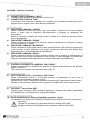
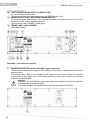
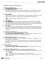
DVA M2M – Funzioni e Comandi
Sezione “Balanced Audio”
1) CONNETTORE DI INGRESSO " INPUT”
Connettore XLR ingresso audio bilanciato a livello linea .
2) CONNETTORE DI USCITA "LINK”
Il connettore “XLR” connesso in parallelo con l’ingresso (1) può essere utilizzato per inviare il
segnale audio in ingresso ad un altro diffusore amplificato.
Sezione “Status”
3) INDICATORE LUMINOSO “LIMITER”
Questo indicatore si illumina di colore rosso per indicare l'intervento del circuito limitatore
interno, il quale evita la distorsione dell'amplificatore e protegge gli altoparlanti dai
sovraccarichi.
Evitare di utilizzare il sistema per lunghi periodi di tempo con l’indicatore luminoso acceso
fisso o lampeggiante.
4) INDICATORE LUMINOSO “SIGNAL”
Questo indicatore si illumina di colore verde per indicare la presenza di un segnale in ingresso
con livello superiore a -20dBu.
5) INDICATORE LUMINOSO “MUTE/PROT”
Questo indicatore di colore giallo indica lo stato dell’amplificatore. Nel normale funzionamento
il led è spento; in caso lampeggi o sia sempre acceso fare riferimento alla tabella della
diagnostica per la verifica dello stato dell’amplificatore.
6) INDICATORE LUMINOSO “READY”
Questo indicatore s'illumina di colore verde per indicare che la tensione di alimentazione di
rete è corretta. Nel normale funzionamento il led è acceso; in caso lampeggi o sia spento fare
riferimento alla tabella della diagnostica per la verifica dello stato dell’amplificatore.
Sezione “Audio Input Control”
7) CONTROLLO SENSIBILITA’ INGRESSO “INPUT SENS”
Questo controllo regola la sensibilità del segnale in ingresso all’amplificatore e del diffusore
passivo DVA M2S
Tale controllo non influisce sul livello dell’uscita “LINK” (2)
Sezione “DSP Setup”
8) SELETTORE ROTATIVO a 10 posizioni “DSP Preset”
Questo commutatore rotativo a 10 posizioni permette di selezionare le nove curve di
equalizzazione predisposte (selettore da 0-8).
La posizione 9 (“user”) è riservata ad operazioni avanzate quali l’aggiornamento del firmware.
Pertanto in tale posizione il diffusore non è operativo e l’amplificatore viene messo in mute.
Sezione “Service”
9) Connettore “Service Data USB”
Tramite questo connettore USB è possibile aggiornare il firmware del modulo amplificatore
DVA M2M tramite un computer ed un programma dedicato.
Sezione “Slave Audio Output”
10) Uscita amplificata per il diffusore DVA M2S (connettore a 4 poli)
Il collegamento tra i diffusori DVA M2M e DVA M2S avviene tramite cavo fornito in dotazione.
Attenzione
Collegare al connettore solo ed esclusivamente il diffusore DVA M2S
Spegnere il diffusore DVA M2M prima di connettere il diffusore DVA M2S.
2
ITALIANO
DVA MINI Digital Array System
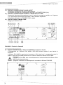
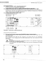
Sezione Alimentazione
11) PRESA DI ALIMENTAZIONE “MAINS INPUT”
Consente la connessione del cavo di alimentazione.
Il connettore utilizzato per il collegamento alla rete è un POWER CON® (blu)
12) PRESA DI ALIMENTAZIONE RILANCIO “MAINS OUTPUT LINK”
Consente di rilanciare l’alimentazione di rete. L’uscita è connessa in parallelo con l’ingresso
(11) e può essere utilizzata per alimentare un altro diffusore amplificato.
Il connettore utilizzato è un POWER CON® (grigio).
13) PORTA FUSIBILE “MAINS FUSE”
Alloggio per fusibile di rete.
DVA M2S – Funzioni e Comandi
Sezione “Slave Audio Input”
1) Ingresso amplificato per il diffusore DVA M2S (connettore a 5 poli)
Il collegamento tra i diffusori DVA M2M e DVA M2S avviene tramite il cavo fornito in
dotazione.
Il diffusore DVA M2S è sprovvisto si crossover e filtri interni per i componenti acustici in
quanto l’uscita del DVA M2M prevede filtri e crossover elettronici dedicati al DVA M2S.
Attenzione
Collegare al DVA M2S solo ed esclusivamente l’uscita dedicata del diffusore DVA
M2M tramite l’apposito cavo.
Spegnere il diffusore DVA M2M prima di connettere il diffusore DVA M2S.
3
ITALIANO
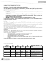
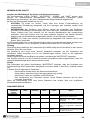
CARATTERISTICHE E PROTEZIONI
Indicazioni delle modalità di funzionamento, di guasto e protezioni
Gli indicatori luminosi (LEDs) “READY”, “MUTE/PROT”, “SIGNAL” e “LIMIT” sono utilizzati anche
per segnalare diverse modalità di funzionamento e differenti tipologie di guasti, mediante sequenze
di lampeggi come riportato nella tabella della diagnostica a seguito.
Sono definite tre tipologie di protezione:
ATTENZIONE: viene rilevato un errore o un malfunzionamento autoripristinante non
grave e le prestazioni del diffusore non vengono limitate
LIMITAZIONE: viene rilevato un errore e vengono limitate le prestazioni del diffusore . Il
livello sonoro viene ridotto oppure vengono disabilitati uno o più funzioni.
Questo stato influisce parzialmente sul funzionamento corretto del diffusore.
Se il problema persiste alle successive accensioni del modulo è necessario contattare il
centro assistenza..
GUASTO: viene rilevato un malfunzionamento grave. Il diffusore viene posto nello stato
di “mute”.
Nel caso di malfunzionamento, prima di contattare il centro di assistenza, provare a spegnere e
riaccendere il modulo per verificare la persistenza del problema.
Raffreddamento
Il raffreddamento dell’amplificatore sul diffusore DVA M2M avviene per convezione sui dissipatori
interni senza l’ausilio di ventole.
La protezione termica è garantita da un circuito interno che controlla la temperatura
dell’amplificatore stesso e lo protegge dal surriscaldamento limitando il volume generale.
Questo intervento viene segnato tramite il lampeggio dell’indicatore luminoso giallo “MUTE/PROT”.
Il corretto volume e tutte le funzioni verranno riprese automaticamente al raggiungimento delle
normali temperature di esercizio.
Protezione
L’ accensione dell’indicatore luminoso Giallo “Mute/Prot” sul modulo M2M indica che l’amplificatore
ha rilevato un malfunzionamento sul diffusore, ponendolo in stato di mute.
Eseguire le seguenti verifiche:
Controllare la corretta connessione alla rete d’alimentazione.
Assicurarsi della corretta tensione d’alimentazione.
Controllare che l’amplificatore non sia surriscaldato.
Scollegare dalla rete di alimentazione il diffusore, attendere qualche minuto e riprovare
Se dopo tali prove l’indicatore non si spenge contattare un centro assistenza autorizzato.
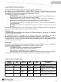
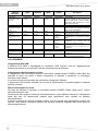
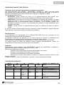
TABELLA DELLA DIAGNOSTICA
STATO O
LED
CONDIZIONE
“READY”
DEL MODULO
Funzionamento normale
Accensione
Spento
Uso normale
Acceso fisso
Anomalia parziale
Acceso fisso
Anomalia totale
Spento
LED
“MUTE/PROT”
LED
“SIGNAL”
LED
“LIMITER”
Acceso per 5
sec.
Spento
Spento
Spento
Funzionamento
normale
Funzionamento
normale
Lampeggio
(lampeggio
veloce)
Acceso fisso
Funzionamento
normale
Funzionamento
normale
Spento
Lampeggio
ciclico
FUNZIONI O DESCRIZIONE
DEL MODULO
Audio in MUTE
Inizializzazione del modulo amplificatore
Audio ATTIVO
Inizializzazione del modulo completata e
corretta
Audio ATTIVO
Il modulo ha rilevato una anomalia parziale e
rimane attivo con funzionalità limitate
Audio in MUTE
Il modulo ha rilevato una anomalia grave e
rimane in protezione
4
ITALIANO
DVA MINI Digital Array System
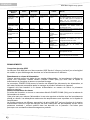
STATO O
LED
CONDIZIONE
“READY”
DEL MODULO
Gestione della temperatura amplificatore
Temperatura
Funzionamento
amplificatore (soglia
normale
termica)
Errori generici
Rilevazione assenza
alimentazione di rete
(Vac)
Sovraccarico di
corrente
Errore di
comunicazione con il
DSP
Errata configurazione
Errato firmware
Modalità USB
Funzione di bootoader
attiva
Telemetria attiva
LED
“MUTE/PROT”
LED
“SIGNAL”
LED
“LIMITER”
FUNZIONI O DESCRIZIONE
DEL MODULO
Lampeggio
ciclico
Funzionamento
normale
Funzionamento
normale
Audio ATTIVO
Il modulo amplificatore riduce il volume, con
step di 0,1dBm fino ad un massimo di 6dBm,
all’aumentare della temperatura al di sopra
della soglia di protezione.
Spento
Acceso
Spento
Spento
Spento
Acceso
Spento
Acceso
Spento
Acceso
Spento
Spento
Acceso
Spento
Spento
Acceso
Spento
Lampeggio
ciclico
(1 lento)
Lampeggio
ciclico
(2 lenti)
Lampeggio
ciclico
(3 lenti)
Durante il normale funzionamento viene
rilevato un buco o una mancanza momentanea
della tensione di alimentazione
Durante il normale funzionamento viene rilevato
un sovraccarico di corrente.
E’ stato rilevato un errore di comunicazione tra
il preamplificatore e il processore del segnale
audio.
La programmazione impostata nel modulo
amplificatore
non
coincide
con
la
configurazione hardware del modulo.
La programmazione del firmware del DSP non
corrispondente con la versione del preamplificatore
Spento
Spento
Lampeggiano alternativamente
Lampeggiano alternativamente
Spento
Spento
E’ attiva la funzione di bootloader nel preamplificatore
Il modulo amplificatore è collegato alla porta
USB per il download della telemetria
COLLEGAMENTI
Collegamento dati USB
Il diffusore DVA M2M è equipaggiato di connettore USB “Service” utile per l’aggiornamento
firmware del modulo o per scaricare i dati sul funzionamento del diffusore.
Collegamento alla alimentazione di rete
Il collegamento alla rete avviene tramite un connettore modello Neutrik POWER CON® (Blu) che
permette di avere una facile e rapida connessione al diffusore e garantisce un bloccaggio
meccanico dello stesso.
Il connettore funge da interruttore per accendere e spegnare il diffusore.
L’apparecchio dovrà essere collegato ad una rete di alimentazione che possa erogare la massima
potenza richiesta.
Rilancio alimentazione di rete
Sul retro del diffusore è presente un connettore Neutrik POWER CON® (Grigio) per il rilancio
dell’alimentazione di rete.
Questa presa ha lo scopo di rilanciare l’alimentazione ad un altro diffusore riducendo i collegamenti
diretti alla rete. Gli assorbimenti massimi degli amplificatori sono riportati sul pannello
dell’amplificatore.
Il numero massimo dei diffusori collegati insieme varia a seconda degli assorbimenti massimi dei
diffusori, deve essere comunque inferiore alla corrente massima erogabile dalla prima presa di
alimentazione/rilancio
5
ITALIANO
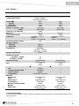
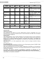
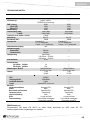
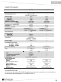
DATI TECNICI
DVA M2M
Sistema
Tipologia amplificatore
Potenza RMS
Alti (HF)
Bassi (LF)
Potenza musicale
Risposta in Frequenza (-6dB)
(-10dB)
Crossover LF-HF (bassi-alti)
Dispersione
Pressione sonora (SPL)
Componenti
Sensibilità ingresso nominale
Impedenza ingresso
Bilanciato
Sbilanciato
Alimentazione
Corrente di accensione
Consumo di corrente
100-120Vac 50-60Hz
220-240Vac 50-60Hz
Dimensioni (LxHxP)
Peso
Processore DSP
DSP
Conversione audio AD/DA
Controllo volume
Equalizzazione
Meccanica
Materiale box
Colore
Rinforzi interni
Forma diffusore
Materiale staffe appendibiltà
Maniglie
Rete frontale
Attivo 2-Amps
Digitale – Classe D
Tecnologia DIGIPRO G3TM
200W
100W
100W
400W
78Hz-19KHz
68Hz-20KHz
1,8KHz
90°x15°
126dB
2 woofer 6,5” – VC 1,5”
Neodimio
2 driver – VC 1” Neodimio
0dB
20Kohm
10Kohm
Auto-Range
100-120Vac 50-60Hz
220-240Vac 50-60Hz
20.6A
DVA M2S
Passivo
--200W
100W
100W
400W
78Hz-19KHz
68Hz-20KHz
90°x15°
126dB
2 woofer 6,5” – VC 1,5”
Neodimio
2 driver – VC 1” Neodimio
----------
1A
0,5A
460x190x345mm
18.1x7.5x13.6 inch.
7.7Kg
16.8lbs
----460x190x345mm
18.1x7.5x13.6 inch.
7.1Kg
15.7lbs
28/56bit
24bit/48KHz
Digitale
9 preset EQ/1 service use
---------
Polipropilene (PP)
Nero
Polipropilene (PP)
Trapezoidale
Acciaio
1 x lato sul retro
Lamiera forata 1.2mm
con foam interno
Polipropilene (PP)
Nero
Polipropilene (PP)
Trapezoidale
Acciaio
1 x lato sul retro
Lamiera forata 1.2mm
con foam interno
CLASSIFICAZIONE EMI
In accordo alle normative EN 55103, l'apparato è progettato e idoneo all'utilizzo in ambienti Elettromagnetici E3 o
inferiori (E2, E1).
6
ENGLISH
DVA MINI Digital Array System
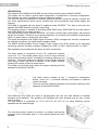
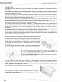
DESCRIPTION
The speakers DVA M2M and DVA M2S are part of the modular system called DVA MINI.
The system can be used in ground stack configuration or suspended in line-array configuration.
The modules use a fast, innovative mechanical fastening method.
This series is ideal for installations in theatres, places of worship, convention centres, concerts and
live music performances which require medium-high sound pressures and limited weight and
footprint.
DVA M2M is equipped with two class D amplifiers series DIGIPRO ® G3, able to drive also the
speaker DVA M2S thanks to a simple, easy wiring.
The amplifier module is capable of delivering 400W RMS (total), 200W RMS for the bass section
and 200W (RMS) for the treble section.
The high efficiency of the modules DIGIPRO ® G3 allows to obtain high output power, with reduced
weight and footprint. Thanks to its low power dissipation, the cooling of the amplifier module takes
place in a static manner, avoiding the use of fans.
The digital pre-amplifier with Digital Signal Processor (DSP) manages the acoustic components,
the frequency response, the limiter and the speaker alerts.
The SMPS (Switched-Mode Power Supply) Power Supply Unit (PSU) thanks to its self-range
technology ensures operation at supply voltages from 100V~ to 120V~ and from 220V~ to 240V~.
Both speakers are provided with the same acoustic components.
The bass section is composed of two 6.5" neodymium woofers
(voice coil 1.5”). The double phase plug in front of each individual
cone avoids horizontal phase overlapping increasing efficiency and
directivity. The double phase plug present in front of each individual
cone brings nearer the point of release of the woofer acoustic
avoiding the overlap of the horizontal phase.
The design of the phase plugs allows the proper matching with the
speakers of the series DVA Mini.
The treble section consists of two 1” neodymium compression
drivers (voice coil 1”) mounted vertically and spaced to optimize
vertical coverage.
The horn has been specially designed for the proper matching of the
speakers of the series DVA Mini.
DVA M2M and DVA M2S are made of polypropylene with two rear side handles to facilitate
transport and installation. The speakers are equipped with steel brackets and an easy, simple
locking system.
The rear bracket is graduated (0°-1.5°-3°-4.5°-6°-8°-10°-12.5°-15°) to allow fastening various
speakers with the desired angle.
The accurate design enables to achieve a constant and precise
coverage of 90° horizontally and 15° in the vertical direction for each
speaker.
7
ENGLISH
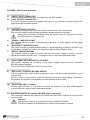
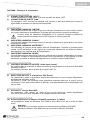
DVA M2M – Functions and controls
"Balanced Audio" section
2) " INPUT” INPUT CONNECTOR
Audio balanced input at line level. It is able to accept “XLR” sockets.
3) "LINK” OUTPUT CONNECTOR
The “XLR” connector connected in parallel with input (1) can be used to send the input audio
signal to another amplified speaker.
"Status" section
4)
“LIMITER” INDICATOR LIGHT
This indicator comes on red to indicate that the internal limiter circuit has tripped.
This prevents amplifier distortion and protects the speakers against overloads.
Always avoid operating conditions where the system works for long periods of time
with LED flashes or it is always ON
5)
6)
7)
“SIGNAL” INDICATOR LIGHT
This indicator comes on green to indicate the presence of an input signal to a level higher
than -20dBu.
“MUTE/PROT” INDICATOR LIGHT
This yellow indicator indicates amplifier status. In normal operating conditions, the LED is off;
if it flashes or is always on, refer to the diagnostics table to check amplifier status.
“READY” INDICATOR LIGHT
This indicator comes on green to indicate that the main power voltage is correct. In normal
operating conditions, the LED is on; if it flashes or is off, refer to the diagnostics table.
"Audio Input control " section
8) “INPUT SENS” INPUT SENSITIVITY CONTROL
This control regulates the sensitivity of the signal amplifier input and of the connected
DVA M2S passive speaker.
This control does not affect the “LINK” (2) output level
"DSP configuration" section
9) “DSP Preset” 10-position ROTARY SWITCH
This 10-position rotary switch makes it possible to select the nine preset equalization curves
(selector 0-8)
Position 9 ("user") is reserved for advanced operations such as firmware update. Therefore in
this position, the speaker is not operating and the amplifier is set to mute.
"Service" section
10) “Service Data USB” Connector
Via this USB connector, it is possible to update the firmware of the DVA M2M amplifier
module using the computer and a dedicated program.
"Slave Audio Output" section
11) Amplified output for the speaker DVA M2S (4-pole connector)
The connection between the speakers DVA M2M and DVA M2S is realized by means of the
supplied cable.
Attention
Connect the connector only and exclusively the speaker DVA M2S
Turn off the speaker DVA M2M before connecting the speaker DVA M2S.
8
ENGLISH
DVA MINI Digital Array System
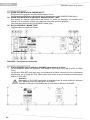
Power supply section
12) "AUTO-RANGE” MAINS INPUT" POWER SOCKET
For connecting the power cable.
The connector used for mains connection is a POWER CON® (blue)
13) “MAINS OUTPUT LINK” RELAUNCH POWER SOCKET
For re-launching the mains power. The output is connected in parallel with input (11) and can
be used to power another amplified speaker.
The connector uses a POWER CON® (grey)
14) "MAINS FUSE" FUSE CARRIER
Mains fuse housing.
DVA M2S – Functions and controls
"Slave Audio Input" section
1) Amplified input for the speaker DVA M2S (5-pole connector)
The connection between the speakers DVA M2M and DVA M2S is realized by means of the
supplied cable.
The speaker DVA M2S is not equipped with crossover and internal filters for acoustic
components, as the output of the DVA M2M provides for filters and electronic crossovers
dedicated to the DVA M2S.
Attention
Connect to the DVA M2S only and exclusively the dedicated output of the speaker
DVA M2M using the specific cable.
Turn off the speaker DVA M2M before connecting the speaker DVA M2S
9
ENGLISH
CHARACTERISTICS AND PROTECTION
Indications of operation model, malfunction, and safeties
The light indicators (LEDs) "READY", "MUTE/PROT", "SIGNAL" and "LIMIT" are also used to
indicate different modes of operation and different types of faults, by flashing sequences as
reported in the diagnostics table below.
The three types of failure are:
WARNING: a non-severe error or auto-reset malfunction is detected and the performance of
the speaker is not limited
LIMITATION: an error is detected and diffuser performance is limited. The sound level is
reduced or one or more amplifiers are disabled. This state partially influences the correct
functioning of the diffuser. If the problem persists the next time the module is turned on,
contact the support center for assistance.
FAILURE: a severe malfunction is detected. The speaker switches to “mute”.
If the case of a malfunction, before contacting the support center, try to turn the module off and on
to check if the problem still exists.
Cooling
The cooling of the amplifier on the speaker DVA M2M is realized by convection on internal heat
sinks without the aid of fans.
Thermal protection is ensured by an internal circuit which controls the temperature of the amplifier
and protects it from overheating by limiting the overall volume.
This intervention is marked by the flashing of a yellow indicator light "MUTE/PROT".
The correct volume and all the functions will be automatically restarted after normal operating
temperatures have been restored.
Protection
When the yellow “MUTE/PROT” LED turns on, it means that a malfunction has been detected on
the speaker, thus setting this to the mute position.
Perform the checks listed below:
Check if the speaker is properly connected to the power supply.
Make sure that the power supply is of correct voltage.
Check that the amplifier is not overheated.
Disconnect the speaker from the mains power supply, wait for a few minutes and connect
it again.
If after these tests the LED is still on, please contact an authorized service center.
DIAGNOSTICS TABLE
STATE OR
CONDITION OF THE
MODULE
LED
“READY”
LED
“MUTE/PROT”
LED
“SIGNAL”
LED
“LIMITER”
Normal operation
Power ON
OFF
ON for 5 sec.
OFF
OFF
Normal use
ON
OFF
Partial fault
ON
Normal
operation
Normal
operation
Normal
operation
Normal
operation
Total fault
OFF
Cycling
flashing (quick
flashes)
ON
OFF
Cycling
flashing (quick
flashes)
FUNCTIONS OR DESCRIPTION OF THE
MODULE
Audio MUTED
Initialization of the amplifier module
Audio ACTIVE
Module initialization complete and correct
Audio ACTIVE
The module has detected a partial anomaly
and remains active with limited functions
Audio MUTED
The module has detected a serious anomaly
and is in protected mode
10
ENGLISH
DVA MINI Digital Array System
STATE OR
CONDITION OF THE
MODULE
LED
“READY”
Amplifier temperature management
Amplifier temperature
Normal
(thermal threshold)
operation
LED
“MUTE/PROT”
LED
“SIGNAL”
LED
“LIMITER”
FUNCTIONS OR DESCRIPTION OF THE
MODULE
Cycling
flashing
Normal
operation
Normal
operation
Audio ACTIVE
The amplifier module reduces the volume, in
steps of 0.1 dBm up to a maximum of 6dBm,
as the temperature rises above the safety
threshold.
Generic errors
No power supply (Vac)
detected
OFF
ON
OFF
OFF
A momentary lack of supply voltage is
detected during normal operation
Current overload
OFF
ON
OFF
ON
A current overload is detected during normal
operation.
OFF
ON
OFF
Cyclic flashing
(1slow flashes)
A communication error between the
preamplifier and the processor of the audio
signal has been detected.
Incorrect configuration
OFF
ON
OFF
Cyclic flashing
(2slow flashes)
The settings of the amplifier module do not
match the hardware configuration of the
module.
Incorrect firmware
OFF
ON
OFF
Cyclic flashing
(3slow flashes)
The DSP firmware does not match the version
of the pre-amplifier
USB Mode
Bootloader
ON
OFF
OFF
They flash alternately
The bootloader function in the pre-amplifier is
active
OFF
The amplifier module is connected to the USB
port for downloading the telemetry
Communication
with the DSP
error
function
Telemetry ON
They flash alternately
OFF
CONNECTIONS
USB Data Link
The speaker DVA M2M is equipped with a USB "Service" connector, useful for the firmware update
of the module or to download speaker operation data.
Connecting to the mains supply
Each active speaker features its own power cable. Connection is done by a Neutrik POWER
CON® (Blue) model which permits easy and fast connection to the speaker as well as being an
excellent locking system.
The POWER CON connector acts as the disconnecting device for the power supply and must be
easily accessible after installation and during use of the speaker
The active speaker must be connected to a power supply able to deliver the maximum required
power.
Main power supply linking
On the rear of the speaker, a Neutrik POWER CON® connector (Grey) offers linking the mains
power supply.
This socket links the power supply to another speaker, thereby reducing the direct connections to
the mains. Maximum amplifier input power is shown on the amplifier panel.
The maximum number of speakers connected to the LINK OUT connector varies depending on the
voltage of power supply used and the type of connected speaker to this socket. Do not exceed in
any case the maximum current / power specified in the data on the panel. This failure can cause
overheating and damage to the products.
11
ENGLISH
TECHNICAL SPECIFICATION
DVA M2M
System
Type of amplifier
RMS power
High (HF)
Low (LF)
Musical power
Frequency response (-6dB)
(-10dB)
Crossover LF-HF (low-high)
Cover range
Sound pressure (SPL)
Component parts
Input sensitivity nominal
Input impendence
Balanced
Unbalanced
Power supply
Inrush current
Current consumption
100-120Vac 50-60Hz
220-240Vac 50-60Hz
Dimensions (LxHxP)
Weight
DSP processor
DSP
Audio conversion AD/DA
Volume control
Equalization
Mechanical parts
Box material
Colour
Box internal reinforcement
Housing shape
Stirrup material
Handle
Frontal grille
Active 2-Amps
Digital – Class D
DIGIPRO G3TM technology
200W
100W
100W
400W
78Hz-19KHz
68Hz-20KHz
1,8KHz
90°x15°
126dB
2 woofer 6,5” –
VC 1,5” Neodymium
2 driver – VC 1” Neodymium
0dB
20Kohm
10Kohm
Auto-Range
100-120Vac 50-60Hz
220-240Vac 50-60Hz
20.6A
DVA M2S
Passive
--200W
100W
100W
400W
78Hz-19KHz
68Hz-20KHz
90°x15°
126dB
2 woofer 6,5” –
VC 1,5” Neodymium
2 driver – VC 1” Neodymium
----------
1A
0,5A
460x190x345mm
18.1x7.5x13.6 inch.
7.7Kg
16.8lbs
----460x190x345mm
18.1x7.5x13.6 inch.
7.1Kg
15.7lbs
28/56bit
24bit/48KHz
Digital
9 preset EQ/1 service use
--------
Polypropylene (PP)
Black
Polypropylene (PP)
Trapezoidal
Steel
1 x each side
Performed sheet 1.2mm
with internal foam
Polypropylene (PP)
Black
Polypropylene (PP)
Trapezoidal
Stell
1 x each side
Performed sheet 1.2mm
with internal foam
EMI CLASSIFICATION
According to the standards EN 55103 this equipment is designed and suitable to operate in E3 (or
lower E2, E1) Electromagnetic environments.
12
DEUTSCH
DVA MINI Digital Array System
BESCHREIBUNG
Die Lautsprecher DVA M2M und DVA M2S sind Teil des kombinierbaren und modularen Systems
DVA MINI.
Das System kann auf dem Boden (ground stack) oder in hängender Position (line-array)
positioniert werden. Die Module verfügen über eine schnelle und innovative mechanische
Befestigungsmethode.
Diese Serie ist ideal für die Installation in Theatern, Kultstätten, Kongresszentren, bei Konzerten
und Live-Musikevents , wo mittel-hohe Schalldruckpegel und geringes Gewicht und geringer
Platzbedarf verlangt werden.
Der DVA M2M ist mit zwei Verstärkern der Klasse D der Serie DIGIPRO® G3 ausgestattet, die in
der Lage sind, über ein einfaches und sofort verlegbares Kabel, auch den Lautsprecher DVA M2S
zu steuern.
Das Verstärkermodul ist in der Lage, 400W EMS (insgesamt), 200W RMS für die Bässe und 200W
(RMS) für die Hochtöne abzugeben.
Die hohe Effizienz der Module DIGIPRO® G3 erlaubt, große Leistungen am Ausgang mit geringem
Gewicht und geringem Platzbedarf zu erreichen. Dank der niedrigen verstreuten Leistung erfolgt
die Kühlung des Moduls auf statische Weise, wodurch die Nutzung von Lüftern vermieden wird.
Der digitale Vorverstärker mit DSP (Digital Signal Processor) verwaltet die akustischen
Komponenten, das Frequenz-Feedback, den Limiter und die Signalisierungen des Lautsprechers.
Die PSU (Power Supply Unit) SMPS (Switches-Mode Power Supply) garantiert, Dank der AutoRange-Technologie, die Funktion bei Versorgungsspannungen von 100V~ bis 120V~ und von
220V~ bis 240V~.
Beide Lautsprecher sind mit denselben akustischen Komponenten ausgestattet.
Der Bass-Bereich besteht aus zwei 6,5"-Neodym-Woofern (voice coil
1,5"). Der doppelte Phase Plug vor jedem einzelnen Kegel näher
bringt dem Punkt der Freigabe der Woofer akustische Vermeidung
der Überlappung der horizontalen Phase.
Die Zeichnung der Phase Plug wurde für die korrekte Kopplung mit
den Lautsprechern der Serie DVA Mini entwickelt.
Der Hochtonbereich besteht aus zwei 1"-Neodym-Compression
Driver (voice coil 1"), die senkrecht montiert und distanziert sind,
um die senkrechte Deckung zu optimieren.
Das Horn wurde speziell für die korrekte Kopplung der
Lautsprecher der Serie DVA Mini entwickelt.
Der DVA M2M und DVA M2S sind aus Polypropylen und haben zwei seitliche hintere Griffe, um
den Transport und die Installation zu erleichtern. Die Lautsprecher sind mit Stahlbügeln und einem
einfachen und leichten Blockierungssystem versehen.
Der hintere Bügel ist graduiert (0°-1,5°-3°-4,5°-6°-8°-10°-12,5°-15°), um die Befestigung der
verschiedenen Lautsprecher im gewünschten Winkel zu erlauben.
Eine akkurate Entwicklung hat es ermöglicht, bei jedem
Lautsprecher eine konstante und präzise Deckung von 90° in der
Waagerechten und 15° in der Senkrechten zu erhalten.
13
DEUTSCH
DVA M2M – Funktionen und Bedienelemente
Abschnitt “Balanced Audio”
1) EINGANGSBUCHSE "INPUT”
Symmetrischer XLR Eingang für Line-Pegel.
2) AUSGANGSBUCHSE "LINK”
Der parallel zum Eingang (1) angeschlossene XLR-Anschluss kann dazu verwendet werden,
das ankommende Audiosignal an einen anderen verstärkten Lautsprecher weiter zu leiten.
Abschnitt “Status”
3) LED “LIMITER”
Diese rote LED leuchtet auf, um das Ansprechen der Limiterschaltung zu signalisieren, die die
Verzerrung des Verstärkers verhindert und die Lautsprecher gegen Überlast schützt.
Vermeiden Sie den Dauerhaften Betrieb im Limit
4)
5)
6)
LED “SIGNAL”
Diese LED leuchtet grün, wenn das Audiosignal anliegt mit einem Pegel von größer -20dBu.
LED “MUTE/PROT”
Diese gelbe LED zeigt den Zustand des Verstärkers an. Während des normalen Betriebs ist
die LED ausgeschaltet; wenn sie blinkt oder ständig leuchtet, kann man der Diagnosetabelle
Informationen zur Kontrolle des Zustands des Verstärkers entnehmen.
LED “READY”
Diese LED leuchtet grün, wenn das Gerät an die richtige Netzspannung angeschlossen ist.
Während des normalen Betriebs ist die LED eingeschaltet; wenn sie blinkt oder ausgeschaltet
ist, kann man der Diagnosetabelle Informationen zur Kontrolle des Zustands des Verstärkers
entnehmen.
Abschnitt “Audio Input Control”
7) EMPFINDLICHKEITSREGLER EINGANG “INPUT SENS”
Dieser Regler dient zum Einstellen der Eingangs-Empfindlichkeit des Verstärkers und des an
ihn angeschlossenen Lautsprechers DVA M2S.
Diese Regelung beeinflusst nicht den Ausgangspegel “LINK” (2).
Abschnitt “DSP configuration”
8) DREHSCHALTER mit 10 Positionen “DSP Preset”
Über diesen Drehschalter mit 10 Positionen können die vorgesehenen neun
Entzerrungskurven (Schalter 0-8)
Die Position 9 ("user") ist für erweiterte Verfahren, wie die Aktualisierung der Firmware,
vorgesehen. Diese Position des Lautsprechers ist nicht operativ und der Verstärker wird auf
Mute gesetzt.
Abschnitt “Service”
9) STECKER “Service Data USB”
Über diesen USB-Stecker kann die Firmware des DVA M2M Verstärkermoduls über einen
Computer und ein eigenes Programm aktualisiert werden.
Abschnitt “Slave Audio Output”
10) Ausgang Verstärker für Lautsprecher DVA M2S (4-poliger Steckverbinder)
Die Verbindung zwischen den Lautsprechern DVA M2M und DVA M2S erfolgt über das
mitgelieferte Kabel.
Achtung
Am Steckverbinder nur den Lautsprecher DVA M2S anschließen.
Den Lautsprecher DVA M2M ausschalten, bevor man den Lautsprecher DVA M2S
anschließt.
14
DEUTSCH
DVA MINI Digital Array System
Fütterung Abschnitt
11) EINBAUSTECKER “AUTO_RANGE MAINS INPUT”
Für den Anschluss des beiliegenden Netzkabels.
Für den Netzanschluss wird ein POWER CON® (blau)Stecker verwendet.
12) EINBAUKUPPLUNG FÜR DIE POWER-WEITERLEITUNG “MAINS OUTPUT LINK”
Er dient zum Durchschleifen der Netzspannung. Der Ausgang ist parallel an den Eingang (11)
angeschlossen und kann zum Speisen eines weiteren verstärkten Lautsprechers verwendet
werden. Einbaukupplung POWER CON® (grau).
13) SICHERUNGSHALTER “MAINS FUSE”
Er enthält die Netzsicherung.
DVA M2S – Funktionen und Bedienelemente
Abschnitt “Slave Audio Input”
1)
15
Eingang Verstärker für Lautsprecher DVA M2S (5-poliger Steckverbinder)
Die Verbindung zwischen den Lautsprechern DVA M2M und DVA M2S erfolgt über das
mitgelieferte Kabel.
Der Lautsprecher DVA M2S hat kein Crossover und interne Filter für die akustischen
Komponenten, da der Ausgang des DVA M2M elektronische Filter und Crossover für DVA
M2S besitzt.
Achtung
Am DVA M2S mit dem dafür vorgesehenen Kabel nur den speziellen Ausgang des
Lautsprechers DVA M2M anschließen.
Den Lautsprecher DVA M2M ausschalten, bevor man den Lautsprecher DVA M2S
anschließt.
DEUTSCH
MERKMALE UND SCHUTZ
Angaben der Betriebsmodi, der Fehler und Schutzvorrichtungen
Die Leuchtanzeigen (LEDs) "READY", "MUTE/PROT", "SIGNAL" und "LIMIT" werden auch
benutzt, um unterschiedliche Betriebsweisen und unterschiedliche Fehlertypen mittels
Blinkfrequenzen anzuzeigen, wie dies in nachstehender Diagnosetabelle aufgeführt ist.
Bei den drei Störungsarten handelt es sich um:
ACHTUNG: Es wurde ein leichter Fehler oder eine leichte Funktionsstörung mit
automatischer Rücksetzung festgestellt und die Leistungen des Verteilers werden nicht
eingeschränkt.
BEGRENZUNG: Bei Ermittlung einer Störung werden die Leistungen des Funktionen
reduziert. Der Schallpegel wird verringert bzw. einer oder mehr Verstärker werden deaktiviert.
Dieser Zustand kann sich teilweise auf die korrekte Betriebsweise des Lautsprechers
auswirken. Falls das Problem auch bei einem späteren Gebrauch des Moduls weiterhin
besteht, muss der Kundendienst eingeschaltet werden, um die Störung zu beheben.
DEFEKT: Es wurde eine schwere Funktionsstörung festgestellt. Der Verteiler wird in den
Status “Mute” geschaltet.
Im Störungsfall sollte man vor der Benachrichtigung des Kundendienstes das Modul zunächst ausund erneut einschalten, um zu überprüfen, ob das Problem nach wie vor vorhanden ist.
Kühlung
Die Kühlung des Verstärkers am Lautsprecher DVA M2M erfolgt durch Konvektion an den internen
Ableitern, ohne Hilfe von Lüftern.
Der Hitzeschutz wird durch einen internen Schaltkreis garantiert, der die Temperatur des
Verstärkers selbst kontrolliert und ihn vor Überhitzungen schützt, indem er die allgemeine
Lautstärke begrenzt.
Dieser Eingriff wird durch das Blinken der gelben Leuchtanzeige "MUTE/PROT" angezeigt.
Das korrekte Volumen und alle Funktionen werden automatisch wieder aufgenommen, wenn die
normalen Betriebstemperaturen wieder erreicht wurden.
Schutz
Das Aufleuchten der gelben Kontrolllampe “MUTE/PROT” bedeutet, dass der Verstärker eine
Funktionsstörung des Lautsprechers festgestellt und diesen daher in den Mute- Zustand versetzt
hat.
In diesem Fall ist folgendes zu überprüfen:
Den korrekten Anschluss an das Stromnetz kontrollieren
Sicher stellen, dass die richtige Versorgungsspannung vorliegt
Kontrollieren, dass der Verstärker nicht überhitzt ist.
Den Lautsprecher vom Stromnetz trennen, einige Minuten abwarten und ihn dann
nochmals anschließen.
Wenn die Kontrolllampe auch nach dieser Wartezeit nicht erlischt, bitte eine qualifizierte
Kundendienststelle kontaktieren.
DIAGNOSETABELLE
STATUS ODER
ZUSTAND DES
MODULS
Normaler Betrieb
Einschaltvorgang
LED
“READY”
LED
“MUTE/PROT”
LED
“SIGNAL”
LED
“LIMITER”
AUS
EIN für 5 sec.
AUS
AUS
Normalbetrieb
EIN
AUS
Normalbetrieb
Normalbetrieb
Partialfehler
EIN
Zyklisches
Blinken
Normalbetrieb
Normalbetrieb
Gesamtfehler
AUS
EIN
AUS
Zyklisches
Blinken
FUNKTIONEN ODER BESCHREIBUNG DES
MODULS
Audio in MUTE
Initialisierung des Verstärkermoduls
Audio EIN
Initialisierung
des
Moduls
erfolgreich
durchgeführt
Audio EIN
Das Modul hat eine teilweise Störung ermittelt
bleibt mit eingeschränkter Betriebsweise
aktiviert
Audio in MUTE
Das Modul hat eine schwere Störung ermittelt
und bleibt im Schutzmodus
16
DEUTSCH
DVA MINI Digital Array System
STATUS ODER
ZUSTAND DES
MODULS
Temperatur Steuerung
Temperatur Verstärker
(thermische Grenze)
LED
“READY”
LED
“MUTE/PROT”
LED
“SIGNAL”
LED
“LIMITER”
FUNKTIONEN ODER BESCHREIBUNG DES
MODULS
Normalbetrieb
Zyklisches
Blinken
Normalbetrieb
Normalbetrieb
Audio EIN
Das Verstärkermodul verringert die Lautstärke
in Schritten von 0,1dBm bis auf maximal
6dBm, wenn die Temperatur über die
Schutzgrenze steigt.
Allgemeine Fehler
Erfassung fehlender
Netzversorgung (Vac)
AUS
EIN
AUS
AUS
Überstrom
AUS
EIN
AUS
EIN
Kommunikationsfehler
mit DSP
AUS
EIN
AUS
Falsche Konfiguration
AUS
EIN
AUS
Falsche Firmware
AUS
EIN
AUS
Zyklisches
Blinken
(1Langsame
Blinkzeichen)
Zyklisches
Blinken
(2Langsame
Blinkzeichen)
Zyklisches
Blinken
(3Langsame
Blinkzeichen)
Während dem normalen Betrieb wird ein Loch
oder
eine
kurzzeitige
fehlende
Versorgungsspannung erfasst
Während dem normalen Betrieb wird
Überstrom erfasst
Es wurde ein Kommunikationsfehler zwischen
Vorverstärker und Prozessor des AudioSignals erfasst.
AUS
AUS
Abwechselndes Blinken
USB-Modi
Funktion Bootloader
aktiv
Telemetrie aktiv
Abwechselndes Blinken
AUS
AUS
Die
im
Verstärkermodul
eingestellte
Programmierung stimmt nicht mit der
Hardware-Konfiguration des Moduls überein.
Die Programmierung der Firmware des DSP
entspricht nicht der Version des Vorverstärkers
Die Funktion Bootloader im Vorverstärker ist
aktiv
Das Verstärkermodul ist am USB-Anschluss
angeschlossen,
um
die
Telemetrie
herunterzuladen
ANSCHLÜSSE
USB-Datenanschluss
Der Lautsprecher DVA M2M ist mit einem USB-Anschluss "Service" ausgestattet, der für die
Aktualisierung der Firmware des Moduls oder für das Herunterladen der Daten über den Betrieb
des Lautsprechers nützlich ist.
Netzanschluss
Jeder Aktivlautsprecher hat ein eigenes Netzkabel. Der Anschluss erfolgt mit einem Netzstecker
Neutrik POWER CON® (Blau), der den einfachen und schnellen Anschluss des Lautsprechers
erlaubt und eine sichere Verriegelung garantiert. Der Stecker dient zugleich als Schalter zum
Einschalten und Ausschalten der Lautsprecher und während der Verwendung des Geräts leicht
zugänglich bleiben
Das Gerät muss an ein Netz angeschlossen werden, dass die verlangte maximale Leistung
abgeben kann.
Power-Weiterführung
Auf der Rückseite des Lautsprechers befindet sich eine Einbaukupplung Neutrik POWER CON®
(grau) für die Weiterleitung der Netzstromversorgung.
Über diese Steckbuchse kann man einen anderen Lautsprecher anschließen, um die Anzahl der
direkten Netzanschlüsse zu reduzieren. Die maximale Stromaufnahme der Verstärker ist auf ihrem
Typenschild angegeben.
Die Anzahl, der maximal aneinander anschließbaren Lautsprecher ist abhängig von ihrer
maximalen Stromaufnahme und vom maximalem Bemessungsstrom der ersten Netzsteckdose.
AUF keinem Fall die auf der Platte angegebenen Ströme überschreiten. Das könnte Überhitzung
und Schäden von Produkten verursachen.
17
DEUTSCH
TECHNISCHE DATEN
DVA M2M
System
Verstärker typ
RMS Leistung
Höhen (HF)
Bässe (LF)
Musikleistung
Frequenzgang (-6dB)
(-10dB)
Crossover LF-HF (Bässe - Höhen)
Abstrahlung
Schalldruck (SPL)
Lautsprecher
Empfindlichkeit eingang
Impedanz eingang
Simmetrisch
Ünsimmetrisch
Netzspannung
Einschaltstrom
Stromaufnahme
100-120Vac 50-60Hz
220-240Vac 50-60Hz
Abmessungen (BxHxT)
Gewicht
DSP PROZESSOR
DSP
Sampling AD/DA
Lautstärke Kontrolle
Preset
Mechanik
Lautsprechergehäuse
Colour
Box internal reinforcement
Lautsprecherform
Interne Verstärkung
Griffe
Frontverkleidung
Aktiv 2-Amps
Digital – klass D
DIGIPRO G3TM technology
200W
100W
100W
400W
78Hz-19KHz
68Hz-20KHz
1,8KHz
90°x15°
126dB
2 woofer 6,5” –
VC 1,5” Neodymium
2 driver – VC 1” Neodymium
0dB
20Kohm
10Kohm
Auto-Range
100-120Vac 50-60Hz
220-240Vac 50-60Hz
20.6A
DVA M2S
Passiv
--200W
100W
100W
400W
78Hz-19KHz
68Hz-20KHz
90°x15°
126dB
2 woofer 6,5” –
VC 1,5” Neodymium
2 driver – VC 1” Neodymium
----------
1A
0,5A
460x190x345mm
18.1x7.5x13.6 inch.
7.7Kg
16.8lbs
----460x190x345mm
18.1x7.5x13.6 inch.
7.1Kg
15.7lbs
28/56bit
24bit/48KHz
Digital
9 preset EQ/1 service use
--------
Kunststoff (PP)
Black
Kunststoff (PP)
Trapezförmig
Stahl
1 x einer pro Seite
1,2mm Stärke hinterlegtem
Schaumstoff geschützt
Kunststoff (PP)
Black
Kunststoff (PP)
Trapezförmig
Stahl
1 x einer pro Seite
1,2mm Stärke hinterlegtem
Schaumstoff geschützt
EMV Einstufung
Entsprechend der Norm EN 55103 ist diese Gerät entwickelt um inE3 (oder E2, E1)
elektromagnetischen Umgebungen zu arbeiten.
18
FRANÇAIS
DVA MINI Digital Array System
DESCRIPTION
Les diffuseurs DVA M2M et DVA M2S font partie du système à éléments et modulaire dénommé
DVA MINI.
Le système est utilisable avec une configuration en appui au sol (ground stack) ou suspendu avec
une configuration line-array (réseau d'enceintes). Les modules utilisent une méthode de fixation
mécanique rapide et innovante.
Cette série est idéale pour des installations dans des théâtres, lieux de culte, centres de congrès,
concerts et spectacles de musique en direct où des pressions acoustiques moyennes-élevées et
des poids et encombrements réduits sont nécessaires.
Le DVA M2M est équipé de deux amplificateurs en classe D de la série DIGIPRO® G3 en mesure
de piloter également le diffuseur DVA M2S grâce à un câblage simple et immédiat.
Le module amplificateur est en mesure de distribuer 400W RMS (totaux), 200W RMS pour la
section des basses et 200W (RMS) pour la section des aigus.
Les hautes performances des modules DIGIPRO® G3 permettent d'obtenir des puissances de
sortie élevées avec des poids et des encombrements réduits. Grâce à sa basse puissance
dissipée, le refroidissement du module amplificateur a lieu de façon statique, en évitant l'emploi de
ventilateurs.
Le préamplificateur numérique avec DSP (Digital Signal Processor) gère les composants
acoustiques, la réponse en fréquence, le limiteur et les signalisations du diffuseur.
La PSU (Power Supply Unit) SMPS (Switched-Mode Power Supply) grâce à la technologie autorange (plage de mesure automatique) garantit le fonctionnement à des tensions d'alimentations de
100V~ à 120V~ et de 220V~ à 240V~.
Les deux diffuseurs sont dotés des mêmes composants acoustiques.
La section des basses est composée de deux haut-parleurs de
graves de 6,5” au néodyme (bobine mobile 1,5”). Le bouchon à
double phase avant chaque cône rapproche du point de rejet de
l'acoustique du woofer éviter le chevauchement de la phase
horizontale.
Le dessin des bouchons de phase a été conçu spécifiquement
pour le couplage correct avec les diffuseurs de la série DVA Mini.
La section des aigus est composée de deux drivers de compression
de 1” au néodyme (bobine mobile 1”) montés verticalement et
espacés pour optimiser la couverture verticale.
Le cornet a été dessiné spécifiquement pour le couplage correct des
diffuseurs de la série DVA Mini.
Le DVA M2M et DVA M2S sont réalisés en polypropylène avec deux poignées latérales
postérieures pour faciliter le transport et l'installation. Les diffuseurs sont équipés d'étriers en acier
et d'un système de blocage facile et simple.
L'étrier postérieur est gradué (0°-1,5°-3°-4,5°-6°-8°-10°-12,5°-15°) pour permettre la fixation des
divers diffuseurs avec la disposition en angle désirée.
Une conception soignée a permis d'atteindre une couverture
constante et précise de 90° dans le sens horizontal et de 15° en
vertical pour chaque diffuseur.
19
FRANÇAIS
DVA M2M – Fonctions et commandes
Section “Balanced Audio”
1) CONNECTEUR D'ENTRÉE “INPUT”
Entrée symétrique au niveau ligne . Elle peut accueillir des prises “XLR”.
2) CONNECTEUR DE SORTIE “LINK ”
Le connecteur “XLR” connecté en parallèle avec l'entrée (1) peut être utilisé pour envoyer le
signal audio en entrée d'une autre enceinte amplifiée.
Section “Status”
3) INDICATEUR LUMINEUX “LIMITER”
Cet indicateur s'allume de couleur rouge pour indiquer l'intervention du circuit limiteur interne
qui évite la distorsion de l'amplificateur et protège les haut-parleurs contre les surcharges
Toujours éviter les conditions d'exploitation où le système fonctionne pendant de
longues périodes de temps avec la LED clignote ou il est toujours ON
4)
5)
6)
INDICATEUR LUMINEUX “SIGNAL”
Cet indicateur s'allume de couleur verte pour indiquer la présence du signal audio à un niveau
supérieur de -20dBu.
INDICATEUR LUMINEUX “MUTE/PROT”
Cet indicateur de couleur jaune indique l'état de l'amplificateur. Pendant le fonctionnement
normal, la LED est éteinte; si elle clignote ou si elle reste allumée fixe, se référer au tableau
de diagnostic pour contrôler l'état de l'amplificateur..
INDICATEUR LUMINEUX “READY”
Cet indicateur s'allume de couleur verte pour indiquer que la tension d'alimentation de réseau
est correcte. Pendant le fonctionnement normal, la LED est allumée; si elle clignote ou si elle
est éteinte, se référer au tableau de diagnostic pour contrôler l'état de l'amplificateur.
Section “Audio Input control”
7) CONTRÔLE SENSIBILITÉ ENTRÉE “Audio Input Control”
Ce contrôle règle la sensibilité du signal en entrée à l'amplificateur et de l'enceinte DVA M2M
branchée à celui-ci.
Ce contrôle n'influence pas le niveau de la sortie “LINK” (2)
Section “DSP configuration”
8) SÉLECTEUR ROTATIF à 10 positions “DSP Preset”
Ce commutateur rotatif à 10 positions permet de sélectionner les neuf courbes d'égalisation
prédisposées (sélecteur de 0-8)
La position 9 (“user”) est réservée à des opérations avancées telles que la mise à jour du
micrologiciel. Donc dans cette position le diffuseur n'est pas opérationnel et l'amplificateur est
mis en mute.
Section “Service”
9) Connecteur “Service Data USB”
Ce connecteur USB permet de mettre à jour le micro logiciel du module amplificateur
DVA MS12 au moyen d'un ordinateur et du programme prévu à cet effet.
Section “Slave Audio Output”
10) Sortie amplifiée pour le diffuseur DVA M2S (connecteur à 4 pôles)
Le raccordement entre les diffuseurs DVA M2M et DVA M2S a lieu par le biais du câble
fourni.
Attention
Raccorder au connecteur seulement et exclusivement le diffuseur DVA M2S
Éteindre le diffuseur DVA M2M avant de raccorder le diffuseur DVA M2S.
20
FRANÇAIS
DVA MINI Digital Array System
Section d'alimentation
11) PRISE D'ALIMENTATION “MAINS INPUT”
Elle permet de connecter le cordon d'alimentation fourni.
Le connecteur utilisé pour le branchement au réseau est du type POWER CON® (bleu)
12) PRISE D'ALIMENTATION RELANCE “MAINS OUTPUT LINK”
Elle permet de relancer l'alimentation de réseau. La sortie est branchée en parallèle avec
l'entrée (11) et peut être utilisée pour alimenter une autre enceinte amplifiée.
Le connecteur utilisé est du type POWER CON® (gris)
13) BLOC À FUSIBLE “MAINS FUSE”
Logement pour le fusible de réseau.
DVA M2S – Fonctions et commandes
Section “Slave Audio Input”
1) Entrée amplifiée pour le diffuseur DVA M2S (connecteur à 5 pôles)
Le raccordement entre les diffuseurs DVA M2M et DVA M2S a lieu par le biais du câble
fourni.
Le diffuseur DVA M2S n'est pas muni de croisements et filtres internes pour les composants
acoustiques car la sortie du DVA M2M prévoit des filtres et des croisements électroniques
dédiés au DVA M2S.
Attention
Raccorder au DVA M2S seulement et exclusivement la sortie dédiée du diffuseur
DVA M2M au moyen du câble prévu à cet effet.
Éteindre le diffuseur DVA M2M avant de raccorder le diffuseur DVA M2S.
21
FRANÇAIS
CARACTERISTIQUES ET PROTECTION
Indications des modes de fonctionnement, de panne et protections
Les voyants lumineux (LED) “READY”, “MUTE/PROT”, “SIGNAL” et “LIMIT” sont aussi utilisés
pour signaler divers modes de fonctionnement et différentes typologies de pannes, au moyen de
séquences de clignotements comme reporté dans le tableau du diagnostic ci-après.
Les trois types de panne sont :
ATTENTION: quand survient une erreur ou un dysfonctionnement sans gravité, avec
restauration automatique, et quand les prestations du diffuseur ne sont pas limitées.
LIMITATION: si une erreur est relevée, les prestations du diffuseur sont limitées. Le niveau
sonore est réduit, ou bien un ou plusieurs amplificateurs sont déshabilités. Cet état influe
partiellement sur le fonctionnement correct du diffuseur. Si le problème persiste aux
allumages successifs du module, il est nécessaire de contacter le centre d'assistance pour
résoudre le problème.
PANNE : quand survient un dysfonctionnement grave. Le diffuseur est placé en état de
“mute”.
En cas de mauvais fonctionnement, avant de contacter le centre d'assistance, essayer d'éteindre
et de rallumer le module pour vérifier la continuité du problème.
Refroidissement
Le refroidissement de l'amplificateur sur le diffuseur DVA M2M a lieu par convection sur les
dissipateurs internes sans l'aide de ventilateurs.
La protection thermique est garantie par un circuit interne qui contrôle la température de
l'amplificateur et le protège contre la surchauffe en limitant le volume général.
Cette intervention est indiquée par le clignotement du voyant lumineux jaune “MUTE/PROT”.
Le volume correct et toutes les fonctions seront reprises automatiquement lorsque les
températures de fonctionnement normales auront été atteintes.
Protection
L'allumage du voyant lumineux jaune “MUTE/PROT” indique que l'amplificateur a détecté un
disfonctionnement sur le diffuseur le plaçant en état de mute.
Effectuer les vérifications suivantes :
Contrôler que le branchement au réseau d'alimentation soit correct.
S'assurer que la tension d'alimentation soit correcte.
Contrôler que l'amplificateur ne soit pas en surchauffe.
Débrancher du réseau d'alimentation le diffuseur et attendre quelques minutes et puis
essayer à nouveau
Si après ces tests, le voyant ne s'éteint pas, contacter un centre d'assistance autorisé.
TABLEAU DE DIAGNOSTIC
ÉTAT OU
LED
CONDITION DU
“READY”
MODULE
Fonctionnement normal
Mise sous tension
Éteint
Utilisation normale
Illuminée
Fautepartielle
Illuminée
Faute franc
Éteint
LED
“MUTE/PROT”
LED “SIGNAL”
Sous tension x
5 s.
Éteint
Éteint
Éteint
Fonctionnement
normal
Fonctionnement
normal
Fonctionnement
normal
Fonctionnement
normal
Éteint
Clignotement
cyclique
Clignotement
cyclique
(Clignotements
Rapides)
Éteint
LED
“LIMITER”
FONCTIONS
MODULE
OU
DESCRIPTION
DU
Audio en MUTE
Initialisation du module amplificateur
Audio ACTIVE
Initialisation du module terminée et correcte
Audio ACTIVE
Le module a relevé une anomalie partielle et
reste actif mais avec des fonctionnalités
limitées
Audio en MUTE
Le module a relevé une anomalie grave et se
met en protection
22
FRANÇAIS
DVA MINI Digital Array System
ÉTAT OU
LED
CONDITION DU
“READY”
MODULE
Gestion amplificateur de température
Température
Fonctionnement
amplificateur (seuil
normal
thermique)
LED
“MUTE/PROT”
LED “SIGNAL”
LED
“LIMITER”
Clignotement
cyclique
Fonctionnement
normal
Fonctionnement
normal
Audio ACTIVE
Le module amplificateur réduit le volume, par
cran de 0,1dBm jusqu'à un maximum de
6dBm, lors de l'augmentation de la
température au-dessus du seuil de protection
Éteint
Illuminée
Éteint
Éteint
Éteint
Illuminée
Éteint
Illuminée
Éteint
Illuminée
Éteint
Configuration
erronée
Éteint
Illuminée
Éteint
Micrologiciel erroné
Éteint
Illuminée
Éteint
Clignotement
cyclique
(1clignotements
lents)
Clignotement
cyclique
(2clignotements
lents)
Clignotement
cyclique
(3clignotements
lents)
Un manque momentané de la tension
d'alimentation est détecté durant le
fonctionnement normal
Une surcharge de courant est détectée durant
le fonctionnement normal.
Une erreur de communication a été détectée
entre le préamplificateur et le processeur du
signal audio.
Mode USB
Fonction
de
bootloader active
Éteint
Éteint
Clignotent alternativement
La fonction de bootloader
préamplificateur est active
Télémétrie active
Clignotent alternativement
Éteint
Le module amplificateur est relié au port USB
pour le téléchargement de la télémétrie
Erreurs génériques
Détection absence
alimentation secteur
(Vac)
Surcharge
de
courant
Erreur
de
communication avec
le DSP
Éteint
FONCTIONS
MODULE
OU
DESCRIPTION
DU
La programmation réglée sur le module
amplificateur ne coïncide pas avec la
configuration hardware du module.
La programmation du micrologiciel du DSP ne
correspond pas à la version du
préamplificateur
dans
le
BRANCHEMENTS
Connexion données USB
Le diffuseur DVA M2M est muni de connecteur USB “Service” utile pour la mise à jour micrologiciel
du module ou pour télécharger les données sur le fonctionnement du diffuseur.
Branchement au réseau d'alimentation
Chaque enceinte active est dotée de son cordon d'alimentation. Le branchement s'effectue au
moyen d'un connecteur modèle Neutrik POWER CON® (Bleu) qui rend aisé et rapide le
branchement de l'enceinte et assure un excellent blocage.
Le connecteur POWER CON assure la fonction de dispositif de déconnexion du alimentation, et
doit rester facilement accessibles après le montage et pendant l'utilisation de l'appareil
L'appareil doit être branché à un réseau d'alimentation en mesure de fournir la puissance
maximum requise.
Relance alimentation de réseau
À l'arrière de l'enceinte, on trouve un connecteur Neutrik POWER CON® (Gris) pour la relance de
l'alimentation de réseau.
Cette prise sert pour relancer l'alimentation à une autre enceinte et réduire ainsi les branchements
directs au réseau. Les absorptions maximums des amplificateurs sont reportées sur la façade de
l'amplificateur.
Le nombre maximum de diffuseur connectés à la prise LINK OUT varie en fonction de la tension
d'alimentation utilisé et le type de diffuseur est relié à cette prise. Ne pas dépasser en tout cas la
puissance maximale / courant spécifié dans les données sur le panneau. Cet échec peut
provoquer une surchauffe et des dommages aux produits
23
FRANÇAIS
DONNES TECHINIQUES
DVA M2M
Système
Typologie amplificateur
Puissance RMS
Haute (HF)
Faible (LF)
Puissance musicale
Réponse en fréquence (-6dB)
(-10dB)
Crossover LF-HF (faible-haute)
Couverture
Pression sonore (SPL)
Composantes
Entrée sensibilité
Impedance entrée
Symétrique
Asymétrique
Alimentation
Courant d'appel
Consommation de courant
100-120Vac 50-60Hz
220-240Vac 50-60Hz
Dimensions (WxHxD)
Poids
PROCESSEUR DSP
DSP
Transformation audio AD/DA
Contrôle du volume
Ègalisation
PIECES MECANIQUES
Matériel Box
Couleur
Box renforcement interne
Forme enceinte
Matériel d'appui Flying
Poignée
Grilles frontales
Active 2-Amps
Digital – Class D
DIGIPRO G3TM technologie
200W
100W
100W
400W
78Hz-19KHz
68Hz-20KHz
1,8KHz
90°x15°
126dB
2 woofer 6,5” –
VC 1,5” Neodymium
2 driver – VC 1” Neodymium
0dB
20Kohm
10Kohm
Auto-Range
100-120Vac 50-60Hz
220-240Vac 50-60Hz
20.6A
DVA M2S
Passive
--200W
100W
100W
400W
78Hz-19KHz
68Hz-20KHz
90°x15°
126dB
2 woofer 6,5” –
VC 1,5” Neodymium
2 driver – VC 1” Neodymium
----------
1A
0,5A
460x190x345mm
18.1x7.5x13.6 inch.
7.7Kg
16.8lbs
----460x190x345mm
18.1x7.5x13.6 inch.
7.1Kg
15.7lbs
28/56bit
24bit/48KHz
Digital
9 preset EQ/1 service use
--------
Polypropylène (PP)
Noir
Polypropylène (PP)
Trapézoïdal
Acier
un de chaque côté
1.2mm et mousse interne
Polypropylène (PP)
Noir
Polypropylène (PP)
Trapézoïdal
Acier
un de chaque côté
1.2mm et mousse interne
CLASSIFICATION EMI
En accord aux les normes EN 55103, l'équipement est conçu et convenable pour une utilisation en
environnement électromagnétique E3 ou inferieur (E2,E1).
24
DVA MINI Digital Array System
ITALIANO
DVA USB Manager
Il firmware del modulo amplificatore può essere aggiornato tramite la porta USB.
Per rendere possibile e facile questo aggiornamento è stato sviluppato un programma dedicato.
Si raccomanda di scaricare il software gratuito DVA USB Manager direttamente dal sito
dB Technologies (www.dbtechnologies.com) nella sezione dedicata “Software &
Controller”
DVA Composer - Simulazione acustica di sistemi serie DVA
DVA Composer è un software di puntamento e simulazione acustica per tutti i modelli Line Array
della serie DVA e relativi Subwoofers.
Tale software permette di gestire un sistema stereo composto da line array e subwoofer,
simulandone separatamente la risposta acustica di entrambi
Vengono inoltre fornite all'utente una serie di informazioni quali: allineamento in fase tra i sistemi
sospesi e i relativi subwoofer a terra; vengono suggeriti gli angoli ottimali tra i moduli che
compongono i line array e i relativi preset di equalizzazione da assegnare, al fine di consentire
anche ad utenti non esperti di ottimizzare le performance del sistema.
Si raccomanda di scaricare gratuitamente il software DVA_Composer direttamente dal
sito dB Technologies (www.dbtechnologies.com) nella sezione dedicata «Software &
Controller»
ENGLISH
DVA USB Manager
The firmware of the amplifier module can be updated via the USB port.
To make this update possible and simple, a dedicated program has been developed.
It is recommended to download DVA USB Manager free software directly from dB
Technologies (www.dbtechnologies.com) in the special section «Software & Controller»
DVA Composer Acoustical Simulation and aiming for DVA Systems
DVA Composer is a software for aiming and simulating acoustical response of all line arrays and
Subwoofers from DVA Series.
The software allows you to set up a stereo system composed by tops and subs, and simulates
separately the acoustical response of both
DVA Composer also gives to the user all the information about phase alignment between flown
systems and ground stacked subwoofers, as well as it suggests an optimized aiming of the line
arrays modules and their suggested EQ presets, in order to guarantee maximum performances
even for non-expert customers.
It is recommended to download DVA_Composer free software directly from dB
Technologies (www.dbtechnologies.com) in the special section «Software & Controller»
25
DEUTSCH
DVA USB Manager
Die Firmware des Verstärkermoduls kann über den USB-Anschluss aktualisiert werden.
Um diesen Vorgang zu ermöglichen und zu vereinfachen, wurde ein dediziertes Programm
entwickelt, das beim Hersteller angefordert und auf einen Computer installiert werden muss.
Wir empfehlen, die Software DVA USB Manager direkt von der Webseite dB
Technologies
(www.dbtechnologies.com) im Abschnitt «software & Controller»
herunterzuladen
DVA Composer Akustiksimulation für Systeme der Serie DVA
DVA Composer ist eine Software zur Beschallungsplanung und simulation für alle Line ArrayModelle der Serie DVA und den zugehörigen Subwoofern.
Sie ermöglicht die Verwaltung eines Stereosystems, das aus Line Arrays und Subwoofern besteht,
wobei das akustische Ansprechprofil jeweils separat simuliert wird.
Dem Nutzer werden eine Reihe von Daten geliefert, z.B. die Phasenanpassung zwischen den
Hängesystemen und den entsprechenden Subwoofern am Boden. Außerdem werden die
optimalen Winkel zwischen den Line Array-Modulen und den entsprechenden Equalizer-Presets
angegeben, so dass auch weniger erfahrene Benutzer die Leistungen des Systems optimieren
können.
Wir empfehlen, die Software DVA_Composer direkt von der Webseite dB Technologies
(www.dbtechnologies.com) im Abschnitt «software & Controller» herunterzuladen
FRANÇAIS
DVA USB Manager
Le micrologiciel du module amplificateur peut être remis à jour par le port USB.
Pour rendre cette mise à jour possible et facile, un programme spécifique a été développé.
On conseille de télécharger gratuitement le logiciel DVA USB Manager directement à
partir du site dB Technologies (www.dbtechnologies.com) dans la section dédiée «
Software & Controller »
DVA Composer Simulation acoustique de systèmes de séries DVA
DVA Composer est un logiciel de direction et simulation acoustique pour tous les modèles de
lignes de source de la série DVA et les caissons de basse relatifs.
Ce logiciel permet de gérer un système stéréo composé de ligne source et de caissons de basse,
simulant séparément la réponse acoustique de chacun des deux
De plus, de nombreuses informations sont fournies à l'utilisateur, comme l'alignement en phase
entre les systèmes suspendus et les relatifs caissons de basse à terre, ou la syggestion d'angles
optimisés entre les modules de ligne de source et les préréglages d'égaliseur relatifs. Cela permet
d'optimiser les performances du système, même pour des utilisateurs non experts.
On conseille de télécharger gratuitement le logiciel DVA_Composer directement à partir
du site dB Technologies (www.dbtechnologies.com) dans la section dédiée « Software &
Controller »
26
DVA MINI Digital Array System
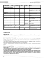
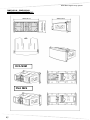
DIMENSIONI - DIMENSIONS
ABMESSUNGEN – DIMENSIONS
DVA M2M
DVA M2S
27
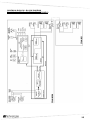
SCHEMA A BLOCCHI - BLOCK DIAGRAM
BLOCKSCHALTBILD - SCHEMAS FONCTIONNELS
28
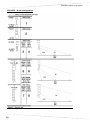
DVA MINI Digital Array System
DVA MINI – Quick configuration
29
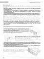
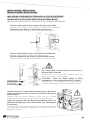
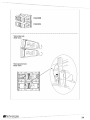
INSTALLAZIONE - INSTALLATION
INSTALLATIONEN - INSTALLATIONS
INDICAZIONE POSIZIONE DEL PERNO NELLA STAFFA POSTERIORE
INDICATION OF THE POSITION OF THE PIN IN THE REAR BRACKET
ANGABE DER POSITION DES ZAPFENS IM HINTEREN BÜGEL
INDICATION POSITION DE LA GOUPILLE SUR L'ETRIER POSTERIEUR
Posizione della staffa a riposo (chiusa all’interno delle staffe)
Position of the bracket in rest position (closed inside the brackets)
Ruhestellung des Bügels (in den Bügeln geschlossen)
Position de l'étrier au repos (fermé à l'intérieur des étriers)
Posizione della staffa in blocco con angolazione desiderata
Position of the bracket in block with desired angle
Blockierungsposition des Bügels mit gewünschtem Winkel
Position de l'étrier bloqué avec disposition en angle désirée
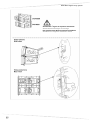
ATTENZIONE
Se il perno NON è inserito all’interno del blocco, il
diffusore NON è bloccato
ATTENTION: If the pin is NOT inserted within the
block, the speaker is NOT locked
ACHTUNG : Wenn der Zapfen NICHT im Block
eingesetzt ist, ist der Lautsprecher NICHT blockiert
ATTENTION : Si la goupille N'est PAS insérée à
l'intérieur du blocage, le diffuseur N'est PAS bloqué
Verificare sempre il corretto inserimento del perno di blocco per
evitare movimenti pericolosi nel caso di fuoriuscita del perno di
stazionamento.
Always check the correct insertion of the lock pin to avoid
dangerous movements in case of release of the parking pin
Immer den korrekten Sitz des Blockierungszapfens prüfen, um
gefährliche Bewegungen beim Heraustreten des Haltezapfens
zu vermeiden.
Toujours vérifier la correcte insertion de la goupille de blocage
pour éviter des mouvements dangereux en cas de sortie de la
goupille de retenue
30
DVA MINI Digital Array System
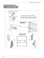
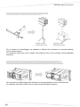
UNIONE DVA M2M – DVA M2S
COMBINATION DVA M2M – DVA M2S
KOMBINATION DVA M2M - DVA M2S
COMBINAISON DVA M2M - DVA M2S
La posizione dei due diffusori è indicativa
The position of the two speakers is indicative
Die Position der beiden Lautsprecher Indikativ
La position des deux haut-parleurs est indicatif
31
32
DVA MINI Digital Array System
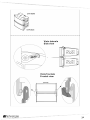
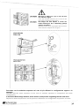
La leva Rossa deve essere posizionata come
indicato in figura per garantire il bloccaggio dei
diffusori
The Red lever must be positioned as shown in the
figure to ensure the locking of the speakers
Der rote Hebel muss wie in Abbildung positioniert
sein, um die Blockierung der Lautsprecher zu
garantieren
Le levier Rouge doit être positionné comme indiqué
sur la figure pour garantir le blocage des diffuseurs
33
34
DVA MINI Digital Array System
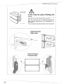
Selezionare l’angolo di copertura desiderato
Select the desired angle of coverage
Den gewünschten Deckungswinkel auswählen
Sélectionner l'angle de couverture désiré
35
Bloccare la staffa con il pin in uno dei due
fori indicati in figura
Lock the bracket with the pin in one of the
two holes indicated in the figure
Den Bügel mit dem Zapfen in einem der
beiden Öffnungen, die in Abbildung gezeigt
werden, blockieren
Bloquer l'étrier avec la goupille dans l'un des
deux orifices indiqués sur la figure
Procedere con la medesima sequenza nel caso di più diffusori in configurazione appesa e in
appoggio
Proceed with the same sequence in the case of multiple speakers in suspended and stack
configuration
In derselben Reihenfolge arbeiten, wenn mehrere Lautsprecher aufgehängt werden und stack
Répéter la même séquence en cas de plusieurs diffuseurs en configuration suspendue en stack
36
DVA MINI Digital Array System
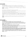
------------------------------------------------------------------------ISTRUZIONI DI SICUREZZA PER ACCESSORI
SAFETY INSTRUCTIONS FOR ACCESSORIES
ZUBEHÖR SICHERHEITSHINWEISE
INSTRUCTIONS DE SÉCURITÉ POUR LES ACCESSOIRES
Per un corretto utilizzo in sicurezza del sistema DVA MINI e al fine di evitare pericoli di ribaltamento e danni a persone, animali e cose,
prima di procedere all'installazione del sistema, verificare sul sito dBTechnologies le configurazioni ammissibili, le indicazioni previste e le
relative prescrizioni di sicurezza. Utilizzare solo parti originali fornite da dBTechnologies.
Si declina ogni responsabilità da un utilizzo inappropriato degli accessori o di dispositivi aggiuntivi non idonei allo scopo.
Conservare ed archiviare tutti i documenti del sistema DVA MINI in un posto sicuro per successive consultazioni.
Installare il diffusore in modo stabile e sicuro, così da evitare qualsiasi condizione di pericolo per l’incolumità di persone e strutture.
Ogni installazione ed utilizzo delle parti fornite come accessori deve essere eseguita in accordo alle istruzioni di montaggio a corredo
dell’accessorio stesso.
For proper and safe use of the system DVA MINI and in order to avoid any risk of overturning and injuries to persons, animals and
property, before to proceed to the system installation, check the dBTechnologies allowable configurations, the particulars provided and
related safety requirements. Use only dB Technologies original parts.
Will not accept any responsibility when inappropriate accessories or not suitable additional devices are used.
Compile and store all DVA MINI system documents in a safe place for future reference.
Make sure that the loudspeaker is securely installed in a stable position to avoid any injuries or damages to persons or property.
Always install parts in accordance with these installation instruction!
Für die ordnungsgemäße und sichere Nutzung des Systems DVA MINI und um jegliche Kippgefahr und Verletzungen von Personen,
Tieren und Sachen, zu vermeiden, bevor auf das System mit der Installation fortfahren, überprüfen der dBTechnologies zulässigen
Konfigurationen, die Angaben zur Verfügung gestellt und damit verbundenen Sicherheitsanforderungen. Nur Original-Teile von
dBTechnologies verwenden.
Falls unpassendes Zubehör verwendet wird, wird jegliche Haftung ausgeschlossen.
Alle Unterlagen des Systems DVA MINI müssen an einem sicheren Ort aufbewahrt waschen für die Zukunft.
Den Lautsprecher auf eine stabile und sichere Art und Weise installieren, um jede Gefahr für Personen oder Sachschäden zu vermeiden.
Jede Installation oder Benutzung der gelieferten Teile muss entsprechend der mitgelieferten Montageanleitung ausgeführt werden.
Pour une utilisation correcte et sûre du système DVA MINI et afin d'éviter tout risque de renversement et les blessures aux personnes,
aux animaux et des biens, avant de procéder à l'installation du système, vérifiez les dBTechnologies configurations admissibles, les
indications prévues et les exigences de sécurité connexes. N'utiliser que les pièces originales fournies par dBTechnologies.
N'accepterons pas toutes les responsabilités lorsque des accessoires inappropriés ou ne conviennent as à des dispositifs
supplémentaires sont utilisés.
Conserver et mettre aux archives en un lieu sûr tous les documents du système DVA MINI pour référence future!
Installer le diffuseur de façon stable et sûre afin d'éviter toute condition de danger pour l'intégrité des personnes et des structures.
Toute installation et utilisation des pièces fournies doit être exécutée conformément aux instructions de montage qui accompagnent le
dispositif.
AVVERTENZA – WARNING – ACHTUNG - ATTENTION
Prima si sospendere il diffusore controllare tutti i componenti da utilizzare (non devono presentare danni, deformazioni, parti
mancanti o danneggiate che possono ridurre la sicurezza dell’installazione).
Before hanging the loudspeaker check all the components for damages, deformations, missing or damaged parts that may
compromise safety during installation.
Bevor man den Lautsprecher aufhängt, alle Teile kontrollieren, sie sollen keine Schäden oder Verformungen, keine fehlenden
oder beschädigten Teile haben, die eine sichere Installation beeinträchtigen könnten.
Avant de suspendre le diffuseur, contrôler tous les composants à utiliser, qui ne doivent présenter aucun dommage, aucune
déformation ou partie manquante ou abimée qui seraient susceptibles de réduire la sécurité de l'installation.
37
AVVERTENZA – WARNING – ACHTUNG - ATTENTION
L'utilizzo del diffusore su supporto piantana deve essere effettuato esclusivamente da personale professionale qualificato,
prestando attenzione a posizionare un piede del supporto piantana in direzione del lato di uscita del suono (lato anteriore del
diffusore) in modo da massimizzare la stabilità del sistema in relazione al suo baricentro.
The installation of the speaker on speaker stand must be carried out exclusively by professionally qualified staff, being careful
to place a speaker stand foot in the direction of the output side of the sound (front side of the speaker) so as to maximize
stability in relation to the centre of gravity of the speaker
Die Benutzung des Lautsprechers mit Ständer und Topplatte darf nur durch qualifiziertes Fachpersonal erfolgen. Hierbei ist
darauf zu achten, dass ein Fuß des Ständers in Richtung der Schallseite (Vorderseite des Lautsprechers) positioniert ist, um
die höchste Stabilität in Bezug auf den Schwerpunkt des Lautsprechers zu erreichen
L'utilisation du diffuseur sur support avec pied doit être effectué par un personnel professionnel qualifié qui doit veiller à
positionner un pied de support en direction du coté où sort le son (côté antérieur du diffuseur) de manière à optimiser la
stabilité par rapport au barycentre du diffuseur
AVVERTENZA – WARNING – ACHTUNG - ATTENTION
Nell'utilizzo dei diffusori con supporto per subwoofer (Pole mount), assicurarsi che il subwoofer di supporto del/i diffusore/i
sia posizionato su una superficie piana, orizzontale e priva di inclinazioni.
When using the speaker with a pole mount for subwoofer, make sure that the subwoofer which supports the speaker is placed
on a flat, horizontal surface without inclinations.
Bei der Verwendung des Lautsprechers mit Hochständer für Subwoofer (Pole Mount ) fall ist darauf zu achten, dass der
Subwoofer unter dem Lautsprecher auf einer Wohnung, horizontalen und frei von Neigungen.
Pour l'utilisation du diffuseur avec support en colonne pour caisson de basse (pole mount) s'assurer que le caisson de basse
de support du diffuseur soit positionné sur une surface plat, horizontale en dépourvue d'inclinaisons.
ACCESSORIO DRK-M5 (flybar per DVA MINI)
ACCESSORY DRK-M5 (flybar for DVA MINI)
Per le istruzioni di assemblaggio tra flybar e diffusori fare riferimento al manuale dedicato incluso
nell’accessorio.
For assembly instructions of the flybar and speakers refer to the included manual dedicated
accessory.
38
DVA MINI Digital Array System
ACCESSORIO DSA-M2 (adattatore per supporto su asta)
ACCESSORY DSA-M2 (stand supporto adaptor)
Supporto con asta
Stand support on pole
Supporto con palo
Stand support on pole
Per le istruzioni di assemblaggio tra adattatore e diffusori fare riferimento al manuale dedicato
incluso nell’accessorio.
For assembly instructions of the adapter and speakers refer to the included manual dedicated
accessory.
ACCESSORIO RC-M2 (Protezione pioggia per modulo connettori DVA M2M)
ACCESSORY RC-M2 (Rain cover protection for connectors module DVA M2M)
Per le istruzioni di assemblaggio fare riferimento al manuale dedicato incluso nell’accessorio.
For assembly instructions refer to the included manual dedicated accessory.
39
40
DVA MINI Digital Array System
41
42
DVA MINI Digital Array System
A.E.B. Industriale Srl
Via Brodolini, 8
Località Crespellano
40053 VALSAMOGGIA
BOLOGNA (ITALIA)
Tel +39 051 969870
Fax +39 051 969725
www.dbtechnologies.com
[email protected]
Codice 420120207 Rev 1.0